EP1933276A1 - Multiband tracking and calibration system - Google Patents
Multiband tracking and calibration system Download PDFInfo
- Publication number
- EP1933276A1 EP1933276A1 EP06025561A EP06025561A EP1933276A1 EP 1933276 A1 EP1933276 A1 EP 1933276A1 EP 06025561 A EP06025561 A EP 06025561A EP 06025561 A EP06025561 A EP 06025561A EP 1933276 A1 EP1933276 A1 EP 1933276A1
- Authority
- EP
- European Patent Office
- Prior art keywords
- camera
- instrument
- light
- camera system
- implant
- Prior art date
- Legal status (The legal status is an assumption and is not a legal conclusion. Google has not performed a legal analysis and makes no representation as to the accuracy of the status listed.)
- Granted
Links
- 238000001514 detection method Methods 0.000 claims abstract description 41
- 230000003287 optical effect Effects 0.000 claims abstract description 31
- 239000007943 implant Substances 0.000 claims abstract description 24
- 238000000034 method Methods 0.000 claims abstract description 20
- 230000003595 spectral effect Effects 0.000 claims abstract description 6
- 238000004590 computer program Methods 0.000 claims abstract description 5
- 230000023077 detection of light stimulus Effects 0.000 claims abstract description 4
- 239000003550 marker Substances 0.000 claims description 14
- 238000001228 spectrum Methods 0.000 claims 2
- 238000013461 design Methods 0.000 description 4
- 238000011156 evaluation Methods 0.000 description 4
- 238000012795 verification Methods 0.000 description 4
- 230000006870 function Effects 0.000 description 3
- 238000002675 image-guided surgery Methods 0.000 description 2
- 238000003384 imaging method Methods 0.000 description 2
- 238000004519 manufacturing process Methods 0.000 description 2
- 238000012986 modification Methods 0.000 description 2
- 230000004048 modification Effects 0.000 description 2
- 230000008569 process Effects 0.000 description 2
- 238000001356 surgical procedure Methods 0.000 description 2
- 238000012360 testing method Methods 0.000 description 2
- 230000009466 transformation Effects 0.000 description 2
- 238000004164 analytical calibration Methods 0.000 description 1
- 238000004458 analytical method Methods 0.000 description 1
- 210000003484 anatomy Anatomy 0.000 description 1
- 230000000712 assembly Effects 0.000 description 1
- 238000000429 assembly Methods 0.000 description 1
- 238000005452 bending Methods 0.000 description 1
- 230000008859 change Effects 0.000 description 1
- 230000001419 dependent effect Effects 0.000 description 1
- 238000013507 mapping Methods 0.000 description 1
- 239000011159 matrix material Substances 0.000 description 1
- 230000007246 mechanism Effects 0.000 description 1
- 230000010287 polarization Effects 0.000 description 1
- 238000001454 recorded image Methods 0.000 description 1
- 230000011514 reflex Effects 0.000 description 1
- 238000000926 separation method Methods 0.000 description 1
- 239000007787 solid Substances 0.000 description 1
- 230000001360 synchronised effect Effects 0.000 description 1
Images


Classifications
-
- A—HUMAN NECESSITIES
- A61—MEDICAL OR VETERINARY SCIENCE; HYGIENE
- A61B—DIAGNOSIS; SURGERY; IDENTIFICATION
- A61B90/00—Instruments, implements or accessories specially adapted for surgery or diagnosis and not covered by any of the groups A61B1/00 - A61B50/00, e.g. for luxation treatment or for protecting wound edges
- A61B90/36—Image-producing devices or illumination devices not otherwise provided for
-
- A—HUMAN NECESSITIES
- A61—MEDICAL OR VETERINARY SCIENCE; HYGIENE
- A61B—DIAGNOSIS; SURGERY; IDENTIFICATION
- A61B34/00—Computer-aided surgery; Manipulators or robots specially adapted for use in surgery
- A61B34/20—Surgical navigation systems; Devices for tracking or guiding surgical instruments, e.g. for frameless stereotaxis
-
- A—HUMAN NECESSITIES
- A61—MEDICAL OR VETERINARY SCIENCE; HYGIENE
- A61B—DIAGNOSIS; SURGERY; IDENTIFICATION
- A61B17/00—Surgical instruments, devices or methods, e.g. tourniquets
- A61B2017/00681—Aspects not otherwise provided for
- A61B2017/00725—Calibration or performance testing
-
- A—HUMAN NECESSITIES
- A61—MEDICAL OR VETERINARY SCIENCE; HYGIENE
- A61B—DIAGNOSIS; SURGERY; IDENTIFICATION
- A61B34/00—Computer-aided surgery; Manipulators or robots specially adapted for use in surgery
- A61B34/20—Surgical navigation systems; Devices for tracking or guiding surgical instruments, e.g. for frameless stereotaxis
- A61B2034/2046—Tracking techniques
- A61B2034/2055—Optical tracking systems
- A61B2034/2057—Details of tracking cameras
-
- A—HUMAN NECESSITIES
- A61—MEDICAL OR VETERINARY SCIENCE; HYGIENE
- A61B—DIAGNOSIS; SURGERY; IDENTIFICATION
- A61B34/00—Computer-aided surgery; Manipulators or robots specially adapted for use in surgery
- A61B34/20—Surgical navigation systems; Devices for tracking or guiding surgical instruments, e.g. for frameless stereotaxis
- A61B2034/2068—Surgical navigation systems; Devices for tracking or guiding surgical instruments, e.g. for frameless stereotaxis using pointers, e.g. pointers having reference marks for determining coordinates of body points
-
- A—HUMAN NECESSITIES
- A61—MEDICAL OR VETERINARY SCIENCE; HYGIENE
- A61B—DIAGNOSIS; SURGERY; IDENTIFICATION
- A61B34/00—Computer-aided surgery; Manipulators or robots specially adapted for use in surgery
- A61B34/20—Surgical navigation systems; Devices for tracking or guiding surgical instruments, e.g. for frameless stereotaxis
- A61B2034/2072—Reference field transducer attached to an instrument or patient
-
- A—HUMAN NECESSITIES
- A61—MEDICAL OR VETERINARY SCIENCE; HYGIENE
- A61B—DIAGNOSIS; SURGERY; IDENTIFICATION
- A61B90/00—Instruments, implements or accessories specially adapted for surgery or diagnosis and not covered by any of the groups A61B1/00 - A61B50/00, e.g. for luxation treatment or for protecting wound edges
- A61B90/36—Image-producing devices or illumination devices not otherwise provided for
- A61B90/361—Image-producing devices, e.g. surgical cameras
- A61B2090/3616—Magnifying glass
-
- A—HUMAN NECESSITIES
- A61—MEDICAL OR VETERINARY SCIENCE; HYGIENE
- A61B—DIAGNOSIS; SURGERY; IDENTIFICATION
- A61B90/00—Instruments, implements or accessories specially adapted for surgery or diagnosis and not covered by any of the groups A61B1/00 - A61B50/00, e.g. for luxation treatment or for protecting wound edges
- A61B90/36—Image-producing devices or illumination devices not otherwise provided for
- A61B90/361—Image-producing devices, e.g. surgical cameras
- A61B2090/3618—Image-producing devices, e.g. surgical cameras with a mirror
-
- A—HUMAN NECESSITIES
- A61—MEDICAL OR VETERINARY SCIENCE; HYGIENE
- A61B—DIAGNOSIS; SURGERY; IDENTIFICATION
- A61B90/00—Instruments, implements or accessories specially adapted for surgery or diagnosis and not covered by any of the groups A61B1/00 - A61B50/00, e.g. for luxation treatment or for protecting wound edges
- A61B90/36—Image-producing devices or illumination devices not otherwise provided for
- A61B90/37—Surgical systems with images on a monitor during operation
- A61B2090/371—Surgical systems with images on a monitor during operation with simultaneous use of two cameras
-
- A—HUMAN NECESSITIES
- A61—MEDICAL OR VETERINARY SCIENCE; HYGIENE
- A61B—DIAGNOSIS; SURGERY; IDENTIFICATION
- A61B90/00—Instruments, implements or accessories specially adapted for surgery or diagnosis and not covered by any of the groups A61B1/00 - A61B50/00, e.g. for luxation treatment or for protecting wound edges
- A61B90/36—Image-producing devices or illumination devices not otherwise provided for
- A61B90/37—Surgical systems with images on a monitor during operation
- A61B2090/373—Surgical systems with images on a monitor during operation using light, e.g. by using optical scanners
-
- A—HUMAN NECESSITIES
- A61—MEDICAL OR VETERINARY SCIENCE; HYGIENE
- A61B—DIAGNOSIS; SURGERY; IDENTIFICATION
- A61B90/00—Instruments, implements or accessories specially adapted for surgery or diagnosis and not covered by any of the groups A61B1/00 - A61B50/00, e.g. for luxation treatment or for protecting wound edges
- A61B90/39—Markers, e.g. radio-opaque or breast lesions markers
- A61B2090/397—Markers, e.g. radio-opaque or breast lesions markers electromagnetic other than visible, e.g. microwave
-
- A—HUMAN NECESSITIES
- A61—MEDICAL OR VETERINARY SCIENCE; HYGIENE
- A61B—DIAGNOSIS; SURGERY; IDENTIFICATION
- A61B90/00—Instruments, implements or accessories specially adapted for surgery or diagnosis and not covered by any of the groups A61B1/00 - A61B50/00, e.g. for luxation treatment or for protecting wound edges
- A61B90/39—Markers, e.g. radio-opaque or breast lesions markers
- A61B2090/3983—Reference marker arrangements for use with image guided surgery
-
- A—HUMAN NECESSITIES
- A61—MEDICAL OR VETERINARY SCIENCE; HYGIENE
- A61B—DIAGNOSIS; SURGERY; IDENTIFICATION
- A61B90/00—Instruments, implements or accessories specially adapted for surgery or diagnosis and not covered by any of the groups A61B1/00 - A61B50/00, e.g. for luxation treatment or for protecting wound edges
- A61B90/39—Markers, e.g. radio-opaque or breast lesions markers
- A61B2090/3995—Multi-modality markers
-
- A—HUMAN NECESSITIES
- A61—MEDICAL OR VETERINARY SCIENCE; HYGIENE
- A61B—DIAGNOSIS; SURGERY; IDENTIFICATION
- A61B34/00—Computer-aided surgery; Manipulators or robots specially adapted for use in surgery
- A61B34/10—Computer-aided planning, simulation or modelling of surgical operations
-
- A—HUMAN NECESSITIES
- A61—MEDICAL OR VETERINARY SCIENCE; HYGIENE
- A61B—DIAGNOSIS; SURGERY; IDENTIFICATION
- A61B90/00—Instruments, implements or accessories specially adapted for surgery or diagnosis and not covered by any of the groups A61B1/00 - A61B50/00, e.g. for luxation treatment or for protecting wound edges
- A61B90/36—Image-producing devices or illumination devices not otherwise provided for
- A61B90/361—Image-producing devices, e.g. surgical cameras
Landscapes
- Health & Medical Sciences (AREA)
- Surgery (AREA)
- Life Sciences & Earth Sciences (AREA)
- Engineering & Computer Science (AREA)
- Medical Informatics (AREA)
- Biomedical Technology (AREA)
- Heart & Thoracic Surgery (AREA)
- Nuclear Medicine, Radiotherapy & Molecular Imaging (AREA)
- Molecular Biology (AREA)
- Animal Behavior & Ethology (AREA)
- General Health & Medical Sciences (AREA)
- Public Health (AREA)
- Veterinary Medicine (AREA)
- Robotics (AREA)
- Oral & Maxillofacial Surgery (AREA)
- Pathology (AREA)
- Length Measuring Devices By Optical Means (AREA)
Abstract
Description
Die vorliegende Erfindung bezieht sich auf ein Mehrbandtracking- und/oder Kalibrier- oder Registrier-System, um ein zum Beispiel medizinisch verwendbares Instrument, wie zum Beispiel eine Schere oder einen Spreader, oder ein Implantat zu kalibrieren oder einen Patienten oder eine zum Beispiel anatomische Struktur zu registrieren und insbesondere um die geometrische Struktur oder Konfiguration eines Instrumentes oder Implantates zu erfassen.The present invention relates to a multi-band tracking and / or calibration or registration system for calibrating, for example, a medically usable instrument, such as a pair of scissors or spreaders, or an implant, or a patient or anatomical structure, for example to register and in particular to capture the geometric structure or configuration of an instrument or implant.
Um ein medizinisches Instrument in der bildgeführten Chirurgie einsetzen zu können, muss dieses Instrument kalibriert bzw. verifiziert oder validiert sein, d,h, es muss bekannt sein, wie die genaue Abmessung, Konfiguration oder Anordnung des Instrumentes ist, da ansonsten aufgrund zum Beispiel einer Verbiegung einer Instrumentenspitze in ein gesundes Gewebe eingegriffen wird, welches neben dem eigentlich zu behandelnden Gewebe liegt, in welches eine unverbogene Instrumentenspitze eingreifen würde.In order to use a medical instrument in image-guided surgery, this instrument must be calibrated, verified or validated. That is, it must be known what the exact size, configuration or arrangement of the instrument is, otherwise due to e.g. Bending an instrument tip is engaged in a healthy tissue, which is located next to the actual tissue to be treated, in which an unexposed instrument tip would intervene.
Eine Vorrichtung und ein Verfahren zum Kalibrieren eines gebogenen Elements sind aus der
Aus der
Die
Aus der
Die
Aus der
Ein System zum Bestimmen der räumlichen Position eines Körpers ist aus der
Es ist eine Aufgabe der vorliegenden Erfindung ein Verfahren und eine Vorrichtung zum einfachen Tracken, Kalibrieren oder Registrieren eines Körpers, wie zum Beispiel eines bevorzugt medizinisch verwendbaren Instrumentes oder Implantats vorzuschlagen.It is an object of the present invention to provide a method and apparatus for easy tracking, calibration or registration of a body, such as a preferably medically usable instrument or implant.
Diese Aufgabe wird durch die Gegenstände der unabhängigen Ansprüche gelöst. Vorteilhafte Ausführungsformen ergeben sich aus den abhängigen Ansprüchen.This object is solved by the subject matters of the independent claims. Advantageous embodiments will be apparent from the dependent claims.
Das erfindungsgemäße Kamerasystem weist mindestens zwei optische Erfassungssysteme oder Kameras auf, welche in einem vorgegebenen Abstand von zum Beispiel 10 bis 1000 mm beispielsweise innerhalb eines Gehäuses angeordnet sind. Erfindungsgemäß ist mindestens ein und vorteilhaft jedes optische Erfassungssystem so ausgelegt, dass gleichzeitig oder hintereinander Licht in einem unterschiedlichen Spektral- oder Wellenbereich erfasst werden kann, wie zum Beispiel Infrarot, sichtbares Licht (zum Beispiel im Bereich von etwa 380 bis etwa 780 nm) und Licht mit einer Wellenlänge im ultravioletten Bereich. Hierdurch ist es möglich, dass mit dem erfindungsgemäßen Kamerasystem sowohl zum Beispiel in Verbindung mit einem an sich bekannten Navigationssystem ein Tracking-Verfahren durchgeführt werden kann, wobei die Kameras oder Erfassungssysteme zum Beispiel Licht im Infrarotbereich erfassen, während andererseits mit den beiden Erfassungssystemen oder Kameras auch zum Beispiel Licht im sichtbaren Bereich erfasst werden kann, um beispielsweise ein Instrument zu kalibrieren, verifizieren oder validieren. Durch das Integrieren mindestens zweier Erfassungsvorrichtungen zur Erfassung von zum Beispiel sichtbarem Licht in die Kameras zur Erfassung von zum Beispiel IR-Licht eines bekannten Stereoskopie-Kamerasystems kann ohne eine signifikante Erhöhung des Gewichts des gesamten Kamerasystems und auch ohne Set-up- oder Synchronisations-Probleme auf einfache Weise eine Vorrichtung geschaffen werden, welche nicht nur zum Tracken von zum Beispiel IR-Licht reflektierenden Markern verwendet werden kann, sondern welche auch das Auswerten von optischen Informationen zum Beispiel im sichtbaren Wellenlängenbereich ermöglicht Somit kann das erfindungsgemäße Kamerasystem auch an Stelle eines bekannten zum Beispiel nur IR-Licht detektierenden Kamerasystems eingesetzt werden, wobei diese Funktionalität beibehalten und um die optische Erfassung in einem anderen Wellenlängenbereich erweitert wird, um zum Beispiel mittels Stereoskopieaufnahmen eine Kalibrierung vorzunehmen.The camera system according to the invention has at least two optical detection systems or cameras, which are arranged at a predetermined distance of, for example, 10 to 1000 mm, for example, within a housing. According to the invention, at least one and advantageously each optical detection system is designed so that light in a different spectral or waveband can be detected simultaneously or sequentially, such as infrared, visible light (for example in the range of about 380 to about 780 nm) and light with a wavelength in the ultraviolet range. This makes it possible that with the camera system according to the invention, for example, in conjunction with a known navigation system, a tracking method can be performed, the cameras or detection systems, for example, detect light in the infrared, while on the other hand with the two detection systems or cameras For example, light in the visible range may be detected, for example, to calibrate, verify or validate an instrument. By integrating at least two detection devices for detecting, for example, visible light into the cameras for detecting, for example, IR light of a known stereoscopic camera system can without a significant increase in the weight of the entire camera system and without set-up or synchronization problems In a simple way, a device can be provided which can not only be used to track, for example, IR light-reflecting markers, but which also enables the evaluation of optical information, for example, in the visible wavelength range Thus, the camera system according to the invention also in place of a known for For example, only IR-light detecting camera system can be used, this functionality is maintained and extended to the optical detection in a different wavelength range, for example, to perform a calibration using stereoscopic images.
Sofern von Wellenlängen- oder Spektralbereichen gesprochen wird, soll erfindungsgemäß auch Licht einer zum Beispiel konstanten Wellenlänge erfasst sein.If one speaks of wavelength or spectral ranges, according to the invention light of, for example, a constant wavelength should also be detected.
Die Modifikation einer Kamera zur Erfassung von Licht eines weiteren anderen Wellenlängenbereiches kann zum Beispiel durch das Vorsehen eines Strahlteilers, wie zum Beispiel eines Prismas oder eines halbdurchlässigen Spiegels, erfolgen, welcher in dem Strahlengang des zum Beispiel durch eine Linse oder Optik eintretenden Lichtes liegt. Das durch den Strahlteiler aufgeteilte eintretende Licht kann zum Beispiel nach der Strahlteilung auf ein Erfassungselement, wie zum Beispiel einen ersten Sensor, zum Beispiel ein bekanntes CCD-Array zur Erfassung von Licht eines ersten Wellenlängenbereiches, und auf einen zweiten Sensor zur Erfassung von Licht eines zweiten anderen Wellenlängenbereiches treffen. Ein System zur Auftrennung von eintretendem Licht ist zum Beispiel in der
Unter dem Begriff Erfassungselement oder CCD-Element soll im Sinne der Erfindung jedes Erfassungselement verstanden werden, mit welchem ein optisches Signal erfasst und zum Beispiel in ein elektrisches Signal umgewandelt werden kann, wie zum Beispiel eine separate Kamera, ein CCD-Chip, ein CMOS Sensor oder ähnliches.For the purposes of the invention, the term detection element or CCD element is intended to mean any detection element with which an optical signal can be detected and converted into an electrical signal, for example a separate camera, a CCD chip, a CMOS sensor or similar.
Es wird angemerkt, dass auch mehr als zwei Erfassungselemente oder CCD-Elemente in einer einzelnen Kamera vorgesehen sein können, um mehr als zwei Spektralbereiche zu erfassen. Dabei können beispielsweise zusätzliche halbdurchlässige Spiegel und/oder Prismen und optional auch zusätzliche Filterelemente in den Kameras verwendet werden, um zum Beispiel UV-Licht, sichtbares Licht und Infrarot-Licht gleichzeitig oder sequentiell zu erfassen.It is noted that also more than two sensing elements or CCD elements may be provided in a single camera to detect more than two spectral regions. In this case, for example, additional semipermeable mirrors and / or prisms and optionally also additional filter elements in the cameras can be used to detect, for example, UV light, visible light and infrared light simultaneously or sequentially.
Weiterhin ist es möglich, dass ein oder mehrere optische Filter verwendet werden, welche vor ein oder mehrere Erfassungselemente, zum Beispiel vor ein CCD-Array, oder in dem Strahlengang des zu dem jeweiligen Erfassungselement gelangenden Lichtes platziert werden, um so die Erfassung von Licht mit unterschiedlicher Wellenlänge durch verschiedene Sensoren gleicher oder unterschiedlicher Bauart zu ermöglichen. Ebenso ist es möglich, dass jeweils speziell zur Erfassung eines bestimmten Wellenlängeukreiches ausgebildete Sensoren verwendet werden. Ist zum Beispiel pro Kamera des erfindungsgemäßen Kamerasystems nur ein einzelnes Erfassungselement, wie zum Beispiel nur ein CCD-Array, vorgesehen, so kann die Erfassung von Licht unterschiedlicher Wellenlängenbereiche dadurch ermöglicht werden, dass zunächst zum Beispiel ein optischer Filter, welcher nur Licht eines ersten Wellenlängenbereichs durchlässt, vor dem Erfassungselement oder in dem Strahlengang des auf das Erfassungselement treffenden Lichtes platziert wird, so dass nur Licht des ersten Wellenlängenbereiches von dem Erfassungselement erfasst werden kann. Nach einer vorgegebenen Zeit, in welcher das Licht des ersten Wellenlängenbereiches erfasst wurde, kann der Filter herausgenommen oder zum Beispiel durch einen anderen Filter ersetzt werden, welcher an der gleichen oder zum Beispiel auch an einer anderen Stelle in den Strahlengang des Lichtes gebracht wird, um Licht eines zweiten Wellenlängenbereiches zu erfassen.Furthermore, it is possible that one or more optical filters are used, which are placed in front of one or more detection elements, for example in front of a CCD array, or in the beam path of the light reaching to the respective detection element, so that the detection of light with different wavelength by different sensors of the same or different design to allow. Likewise it is possible that in each case Specially designed for detecting a specific wavelength range trained sensors are used. If, for example, only a single detection element, such as only a CCD array, is provided per camera of the camera system according to the invention, the detection of light of different wavelength ranges can be made possible by, for example, first an optical filter which only has light of a first wavelength range is placed in front of the detection element or in the beam path of the incident on the detection element light, so that only light of the first wavelength range can be detected by the detection element. After a predetermined time, in which the light of the first wavelength range has been detected, the filter can be taken out or replaced, for example, by another filter which is brought into the beam path of the light at the same or, for example, at another point To detect light of a second wavelength range.
Ein erfindungsgemäß verwendbarer Filter kann sowohl ein passives Filterelement sein, welches sich nicht verändert wie zum Beispiel ein Farbfilter, oder ein aktiv steuerbarer Filter, wie zum Beispiel ein Polarisationsfilter.A filter which can be used according to the invention can be both a passive filter element which does not change, for example a color filter, or an actively controllable filter, for example a polarization filter.
Weiterhin ist es möglich ein erfindungsgemäßes Kamerasystem zum Beispiel durch das Vorsehen eines beweglichen Spiegels zu schaffen, welcher zum Beispiel in einer ersten Position Licht auf ein erstes Erfassungselement und in einer zweiten zum Beispiel weggeklappten oder gedrehten Position Licht auf ein zweites Erfassungselement lenkt, Dabei kann der bewegliche Spiegel zum Beispiel wie in einer an sich bekannten Spiegelreflexkamera aufgebaut sein und durch eine wie zum Beispiel aus einer Spiegelreflexkamera bekannte Mechanik bewegt werden, um je nach gewünschtem zu erfassenden Wellenlängenbereich das auf den Spiegel auftreffende Licht zu dem jeweils geeigneten Sensor zu lenken.Furthermore, it is possible to provide a camera system according to the invention, for example, by providing a movable mirror which, for example, directs light to a first detection element in a first position and light to a second detection element in a second, for example, folded or rotated position movable mirrors, for example, be constructed as in a conventional SLR camera and be moved by a known as, for example, a single-lens reflex mechanism to guide depending on the desired wavelength range to be detected incident on the mirror light to the respective suitable sensor.
Die Bildwechselfrequenz, mit welcher eine Kamera beispielsweise nur sequentiell Licht unterschiedlicher Wellenlänge erfasst, kann beispielsweise im Bereich von 50 ms pro Bild liegen, so dass zum Beispiel in einer Sekunde jeweils 10 Bilder in einem ersten Wellenlängenbereich und jeweils 10 Bilder in einem zweiten davon verschiedenen Wellenlängenbereich erfasst werden.The frame rate at which a camera captures, for example only sequentially light of different wavelengths, for example, in the range of 50 ms per image, so that, for example, in one second each 10 images in a first wavelength range and 10 images in a second different wavelength range be recorded.
Da bei allen oben beschriebenen Ausführungsformen des erfindungsgemäßen Kamerasystems die gleiche Optik, durch welche Licht in die Kamera eintritt, verwendet werden kann, können auf einfache Weise die korrespondierenden Pixel, also ein Pixel-zu-Pixel Verhältnis, zwischen den zwei Abbildungs-Modalitäten bestimmt werden. Beispielsweise kann die Transformationsvorschrift zur Abbildung eines Pixels in einem ersten zum Beispiel IR-Bild auf ein korrespondierendes Bild zum Beispiel im sichtbaren Bereich bekannt sein, so dass bestimmt werden kann, wo die im IR-Bereich gut sichtbaren Marker an dem im sichtbaren Licht gut erkennbaren medizinischen Instrument angeordnet sind, um so das Instrument tracken und gleichzeitig auch kalibrieren zu können. Idealerweise kann zum Beispiel eine direkte Abbildung (mapping) der jeweiligen Pixel eines in einem ersten Wellenlängenbereich aufgenommenen Bildes auf das korrespondierende Pixel eines in einem zweiten anderen Wellenlängenbereich aufgenommenen Bildes vorliegen, so dass die von dem gleichen oder zwei unterschiedlichen Erfassungselementen erfassten Bilder in zwei unterschiedlichen Wellenlängenbereichen zum Beispiel einfach übereinander gelegt werden können, um die kombinierte Information aus der Erfassung beider Wellenlängenbereiche in einem einzigen Bild zur Verfügung zu haben.Since in all the embodiments of the camera system according to the invention described above, the same optics, by which light enters the camera, can be used In a simple way, the corresponding pixels, ie a pixel-to-pixel ratio, can be determined between the two imaging modalities. By way of example, the transformation rule for imaging a pixel in a first, for example, IR image onto a corresponding image, for example in the visible region, can be known, so that it is possible to determine where the markers, which are clearly visible in the IR region, become clearly visible in visible light medical instrument are arranged so as to be able to track the instrument and calibrate at the same time. Ideally, for example, a direct mapping of the respective pixels of an image captured in a first wavelength range to the corresponding pixel of an image captured in a second, different wavelength range may occur, such that the images captured by the same or two different detector elements are in two different wavelength ranges For example, they can simply be superimposed to provide the combined information from capturing both wavelength ranges in a single image.
Im Gegensatz zur Verwendung von externen Bildquellen muss bei dem erfindungsgemäßen Kamerasystem kein Synchronisations- Verfahren durchgeführt werden, da die Synchronisation der einzelnen Kamera-Baugruppen oder Kamera-Teilelemente, wie zum Beispiel beweglicher Spiegel oder Filter oder verschiedener Erfassungselemente, bereits bei oder nach der Herstellung des Kamerasystems durch Hardware-, Firmware- oder Software-Einstellung oder Anpassung gelöst werden kann, so dass zum Beispiel bei dem Einsatz des Kamerasystems zur Navigation korrespondierende Stereo-Videobilder voll synchronisiert zusätzlich zum Tracken der IR-Marker zur Verfügung gestellt werden können. Hierzu muss das Kamerasystem lediglich kalibriert werden, was beispielsweise vor der ersten Anwendung zum Beispiel durch das Erfassen zweier Testbilder und den nachfolgenden Abgleich der beiden Testbilder, zum Beispiel zum Bestimmen der oben erwähnten Transformationsvorschrift, durchgeführt werden kann.In contrast to the use of external image sources, no synchronization process has to be carried out in the camera system according to the invention, since the synchronization of the individual camera assemblies or camera sub-elements, such as movable mirrors or filters or different detection elements already during or after the production of the Camera system can be solved by hardware, firmware or software setting or customization, so that, for example, when using the camera system for navigation corresponding stereo video images fully synchronized in addition to tracking the IR markers can be provided. For this purpose, the camera system only has to be calibrated, which can be carried out, for example, before the first application, for example by recording two test images and the subsequent alignment of the two test images, for example to determine the above-mentioned transformation rule.
Mit dem erfindungsgemäßen Kamerasystem kann somit zum Beispiel eine berührungslose Verifikation eines Instrumentes durchgeführt werden, wobei im Vergleich zu bekannten Verfahren auf die Verwendung eines Kalibrier-Instrumentes, wie zum Beispiel einer Instrumenten-Kalibrier-Matrix (Instrument Calibration Matrix; ICM), verzichtet werden kann.Thus, for example, a non-contact verification of an instrument can be carried out with the camera system according to the invention, whereby the use of a calibration instrument, such as an instrument calibration matrix (ICM), can be dispensed with compared to known methods ,
Aus den mindestens zwei Aufnahmen eines Objektes kann auch ein Modell der dreidimensionalen Oberfläche des Objektes rekonstruiert werden, wie zum Beispiel in dem Artikel "Shape from Stereo Using Fine Correlation: Method and Error Analysis" von Frédéric Devernay und Olivier Faugeras beschrieben, welcher bezüglich der technischen Lehre der Rekonstruktion oder Erzeugung einer dreidimensionalen Oberfläche oder eines dreidimensionalen Oberflächenmodells aus zum Beispiel einer Stereo-Aufnahme in die vorliegende Erfindung aufgenommen wird.From the at least two images of an object, a model of the three-dimensional surface of the object can also be reconstructed, as described for example in the article "Shape from Stereo Using Fine Correlation: Method and Error Analysis" by Frédéric Devernay and Olivier Faugeras The teaching of reconstructing or creating a three-dimensional surface or a three-dimensional surface model from, for example, a stereo image is incorporated into the present invention.
Vorteilhaft können eine oder mehrere Lichtquellen, wie zum Beispiel Leuchtdioden, Laser oder Lampen, an einer oder mehreren Kameras, zum Beispiel um eine Lichteintrittsöffnung oder Linse der Kameras herum, angeordnet werden. Vorteilhaft sind die Lichtquellen an der jeweiligen Kamera so ausgelegt, dass Licht in mindestens einem der von dem Kamerasystem erfassbaren Wellenlängenbereiche emittiert wird, wie zum Beispiel Infrarot-Licht, welches zum Beispiel an reflektierenden Oberflächen, beispielsweise einem Marker, reflektiert und wieder zur Kamera zurückgesandt wird. Es ist auch möglich, dass Lichtquellen unterschiedlicher Art an einer Kamera vorgesehen sind, wie zum Beispiel Lampen zur Emission von sichtbarem Licht, LED's oder Laser. Wird als ein Licht aussendendes oder Projektions-Element zum Beispiel ein Laser oder ein Video-Projektor verwendet, so kann mit so genanntem "strukturiertem Licht" ("structured light") die Rekonstruktion von dreidimensionalen Oberflächen vereinfacht werden, wie in dem Artikel "
Eine vor den jeweiligen Erfassungselementen der Kamera liegende Optik kann als variable Optik vorgesehen sein, um Einstellvorgänge, wie zum Beispiel Zoom oder Fokus, welche auch aus der Fotografie bekannt sind, vornehmen zu können. Dabei kann die variable Optik beispielsweise manuell oder elektronisch eingestellt werden, um das Kamerasystem zum Beispiel für die möglichst optimale Erfassung eines Objektes in einem vorgegebenen Abstand von dem Kamerasystem zu konfigurieren.An optical system located in front of the respective detection elements of the camera can be provided as variable optics in order to be able to carry out setting operations, such as zoom or focus, which are also known from photography. In this case, the variable optics can be set, for example manually or electronically, in order to configure the camera system, for example, for the best possible detection of an object at a predetermined distance from the camera system.
Vorzugsweise ist eine Recheneinheit mit beiden Kameras verbunden, welche die von den jeweiligen Kameras aufgenommenen Bilder enthalten und zum Beispiel als Stereobilder verarbeiten oder auswerten kann, um beispielsweise nach Durchführung eines 3D-Rekonstruktionsverfahrens eine Kalibrierung vorzunehmen.Preferably, an arithmetic unit is connected to both cameras, which contain the images taken by the respective cameras and, for example, process them as stereo images or evaluate, for example, to perform a calibration after performing a 3D reconstruction method.
Optional können bei dem erfindungs gemäßen Kamerasystem auch drei oder mehr Kameras verwendet werden, welche vorzugsweise jeweils so ausgelegt sind, dass Licht in mindestens zwei verschiedenen Wellenbereichen erfasst werden kann.Optionally, in the fiction, contemporary camera system, three or more cameras are used, which are preferably each designed so that light can be detected in at least two different wavelengths.
Gemäß einem weiteren Aspekt bezieht sich die Erfindung auf ein Navigationssystem mit einem wie oben beschriebenen Kamerasystem.In another aspect, the invention relates to a navigation system having a camera system as described above.
Die Erfindung bezieht sich weiterhin auf eine Vorrichtung zum Kalibrieren eines bevorzugt medizinisch verwendbaren Instrumentes, an welchem mindestens ein Marker oder ein Referenzstern angebracht ist, mit einer Recheneinheit und einem damit verbundenen Speicher, in welchem Präkalibrier-Daten mindestens eines medizinischen Instrumentes abgelegt sind. Weiterhin ist mindestens eine wie oben beschriebene Kamera vorgesehen, mit welcher sowohl die an dem Instrument angebrachten Marker zum Beispiel mittels reflektiertem IR-Licht erfasst werden können, wobei die Kamera mit einer Recheneinheit verbunden ist, welche die räumliche Position des Instrumentes anhand der erfassten Marker-Bilddaten und optional anhand der Präkalibrierdaten ermitteln kann. Die Vorrichtung weist weiterhin eine Kamera auf, welche in die obige Kamera integriert ist und Licht eines weiteren Wellenlängenbereichs erfassen kann, welcher von der obigen Kamera zum Beispiel nicht erfasst werden kann, mit welcher das Instrument selbst oder die Geometrie oder Abmessung bestimmter Teilbereiche davon erfasst werden können, wobei die Kamera ebenfalls mit der Recheneinheit verbunden ist, so dass in der Recheneinheit ein Vergleich der von der Kamera optisch erfassten Instrumenten-Daten mit den in dem Speicher abgelegten Präkalibrier-Daten durchgeführt werden kann. Dabei ist die Kamera zur Erfassung der Marker-Positionen identisch mit der Kamera zur optischen Erfassung des Instrumentes. Ebenso ist es möglich mit der gleichen Kamera die Position der Marker zu erfassen und so das mit den Markern verbundene Instrument zu tracken und das Instrument selbst oder Abmessungen davon zu erfassen.The invention further relates to a device for calibrating a preferably medically usable instrument to which at least one marker or a reference star is attached, with a computing unit and a memory connected thereto, in which pre-calibration data of at least one medical instrument are stored. Furthermore, at least one camera as described above is provided with which both the markers attached to the instrument can be detected, for example, by means of reflected IR light, the camera being connected to a computing unit which determines the spatial position of the instrument on the basis of the detected markers. Can determine image data and optionally based on the pre-calibration data. The apparatus further comprises a camera which is integrated in the above camera and can detect light of a further wavelength range, which can not be detected by the above camera, for example, with which the instrument itself or the geometry or dimension of certain portions thereof are detected can, wherein the camera is also connected to the arithmetic unit, so that in the arithmetic unit, a comparison of the optically detected by the camera instrument data with the stored in the memory Präkalibrier data can be performed. The camera for detecting the marker positions is identical to the camera for optical detection of the instrument. It is also possible with the same camera to detect the position of the markers and thus to track the instrument connected to the markers and to capture the instrument itself or dimensions thereof.
Weiterhin bezieht sich die Erfindung auf ein System mit einer wie oben beschriebenen Vorrichtung und einem Instrument, an welchem mindestens ein Marker angebracht ist.Furthermore, the invention relates to a system with a device as described above and an instrument to which at least one marker is attached.
Bei einem erfindungsgemäßen Verfahren zum Kalibrieren, Verifizieren oder Validieren eines bevorzugt medizinisch verwendbaren Instrumentes oder Implantats (nachfolgend auch als Instrument) bezeichnet, an welchem mindestens ein Marker und bevorzugt drei Marker zum Beispiel in Form eines so genannten Referenzsternes oder mehrere Marker mit bekannter fester oder sich zum Beispiel in Abhängigkeit von der Konfiguration des Instrumentes veränderbarer Geometrie angebracht sind, wird die Position des Instrumentes im Raum auf bekannte Art mittels eines Navigationssystems zum Beispiel mit einer IR-Stereokamera anhand der Marker, welche zum Beispiel als reflektierende Oberflächen oder Kugeln ausgebildet sein können, ermittelt. Zur Erfassung der Position des Instrumentes ist eine in mindestens eine IR-Kamera integrierte Kamera vorgesehen, welche zum Beispiel sichtbares Licht erfassen kann, welches von dem Instrument ausgesandt oder reflektiert wird, wobei die Kamera bevorzugt kalibriert ist und die Position der Kamera im Raum auch bekannt oder definiert ist. Weiterhin wird die Geometrie, also zum Beispiel eine oder mehrere Ansichten, Abbildungen oder Umrisse des Instrumentes aus einer oder verschiedenen Richtungen optisch mittels mindestens einer Kamera erfasst, wobei diese Kamera die gleiche ist, welche zum Erfassen der Position der Marker verwendet wird, oder auch eine von dieser Kamera verschiedene zweite Kamera sein kann, mit welcher Bilder zum Beispiel im sichtbaren Wellenlängenbereich aufgenommen werden können.In a method according to the invention for calibrating, verifying or validating a preferably medically usable instrument or implant (hereinafter also referred to as instrument) to which at least one marker and preferably three markers, for example in the form of a so-called reference star or more markers with known solid or For example, depending on the configuration of the variable geometry instrument, the position of the instrument in space is determined in a known manner by means of a navigation system, for example with an IR stereo camera based on the markers, which may, for example, be reflective surfaces or spheres. determined. For detecting the position of the instrument, a camera integrated in at least one IR camera is provided, which, for example, can detect visible light emitted or reflected by the instrument, the camera preferably being calibrated and also knowing the position of the camera in the room or defined. Furthermore, the geometry, that is, for example, one or more views, images or outlines of the instrument from one or more directions optically detected by at least one camera, this camera is the same, which is used to detect the position of the marker, or a from this camera can be different second camera, with which images can be recorded, for example, in the visible wavelength range.
Die Geometrie oder Kalibrier-Daten des Instrumentes sind in einer Software oder einem Computer gespeichert, so dass die dreidimensionale Darstellung des Instrumentes zum Beispiel in einer Datenbank abgelegt ist. Diese gespeicherten so genannten Präkalibrierdaten werden mit der von der Kamera erfassten Geometrie des Instrumentes verglichen, um durch diesen Vergleich mit den optischen Erfassungsdaten festzustellen, ob die optisch erfassten und die tatsächliche Geometrie oder Ausbildung des Instrumentes darstellenden Daten mit den Präkalibrierdaten übereinstimmen. Es wird somit eine Zuordnung zwischen zum Beispiel im IR-Bereich erfassten sogenannten Tracking-Daten und einem im sichtbaren Bereich erfassten Kamerabild vorgenommen, wobei im Falle der Übereinstimmung der Kamerabilddaten mit den Präkalibrier-Daten das Instrument kalibriert bzw. verifiziert oder validiert ist und im Falle eines festgestellten Unterschiedes oder eine Abweichung von den Präkalibrier-Daten zum Beispiel eine Fehlermeldung ausgegeben werden kann, so dass das Instrument kalibriert werden muss oder die Präkalibrier-Daten, welche zur nachfolgenden Navigation verwendet werden, an die optischen Erfassungsdaten angepasst werden. Vorzugsweise werden aus einem dreidimensionalen Daten- oder Software-Modell des Instruments jeweils diejenigen Ansichten oder Umrisse des Instrumentenmodells berechnet, welche der mittels der Marker gemessenen Orientierung oder Relativ-Position des realen Instruments zur Kamera entsprechen.The geometry or calibration data of the instrument are stored in a software or a computer, so that the three-dimensional representation of the instrument, for example, stored in a database. These stored so-called pre-calibration data are compared with the camera-captured geometry of the instrument to determine, by this comparison with the optical detection data, whether the optically detected data representing the actual geometry or design of the instrument matches the pre-calibration data. Thus, an association is made between so-called tracking data acquired, for example, in the IR range and a camera image recorded in the visible range, in which case the instrument is calibrated or verified or validated in the case of matching the camera image data with the precalibrating data, and in the case for example, an error message may be output so that the instrument needs to be calibrated or the pre-calibration data used for subsequent navigation may be adapted to the optical detection data. Preferably, from a three-dimensional data or software model of the instrument respectively those views or outlines of the instrument model which correspond to the orientation or relative position of the real instrument to the camera measured by the markers.
Wenn man davon ausgeht, dass das vom Rechner berechnete Bild auf Basis der erfassten Position des als dreidimensionales Modell bekannten Instruments im Raum und des Wissens um die Kalibrierung der Video-Kamera die Darstellung oder Sicht oder ein Modell der Welt bzw. eines Instrumentes durch den Computer oder eine Software ist und die von einer Kamera erfassten Videoeingabedaten die Situation in der realen oder echten Welt, also zum Beispiel ein tatsächliches vorhandenes Instrument, zeigen, so würde im Falle einer genau kalibrierten Videokamera, also einer Kamera mit bekannter Position und Ausrichtung und Erfassungsbereich und eines registrierten oder kalibrierten medizinischen Instrumentes das vom Rechner berechnete Bild für ein präkalibriertes Instrument exakt mit dem Bild zusammenfallen, welches in der Videoeingabe gesehen wird. Falls dies nicht der Fall ist, ist entweder die Kalibrierung oder Abstimmung der Kamera fehlerhaft oder das Instrument entspricht nicht den Präkalibrier-Daten, da es zum Beispiel aufgrund häufigen Gebrauchs verbogen wurde. Wenn angenommen wird, dass die Kalibrierung der Kamera während des gesamten Verfahrens korrekt ist, so kann mit dem von der Kamera erfassbaren kalibrierten Volumen eine zuverlässige Verifikation von Instrumenten, zu welchen Präkalibrier-Daten vorliegen, durchgeführt werden.Assuming that the computer calculated image based on the detected position of the known as a three-dimensional model instrument in space and the knowledge about the calibration of the video camera, the representation or view or a model of the world or an instrument by the computer or a software is and the video input data captured by a camera show the situation in the real or real world, for example, an actual existing instrument, so in the case of a precisely calibrated video camera, ie a camera with a known position and orientation and detection range and of a registered or calibrated medical instrument, the computer calculated image for a precalibrated instrument coincides exactly with the image seen in the video input. If this is not the case, either the calibration or tuning of the camera is faulty, or the instrument does not match the precalibrating data because it has been bent due to frequent use, for example. Assuming that the calibration of the camera is correct throughout the procedure, with the calibrated volume detectable by the camera, reliable verification of instruments for which pre-calibration data is available can be made.
Die zum Beispiel in einem Computer gespeicherten Daten, welche die Geometrie und optional auch mögliche Freiheitsgrade des Instrumentes definieren, sind als Präkalibrier-Daten zum Beispiel als eine Beschreibung des dreidimensionalen Objektes für ein Navigationssystem zum Beispiel in einer Datenbank gespeichert und können beispielsweise ein dreidimensionales Modell darstellen, welches die genaue Form eines Objekts oder Instruments und die Position eines jeden Markers oder Referenz-Arrays auf dem Objekt beschreibt. Das Navigationssystem oder ein Computer kann das dreidimensionale Modell darstellen, welches dem Instrument entspricht, das der Chirurg verwendet. Die Beschreibung des prakalibrierten Instrumentes kann zum Beispiel die Information umfassen, welche Bereiche oder funktionelle Stellen oder Flächen des Instrumentes verifiziert werden müssen. Ebenso können Informationen als Präkalibrier-Daten gespeichert werden, mit welchen mögliche Formen, welche das Instrument annehmen kann, festgelegt werden, wie zum Beispiel Informationen bezüglich möglicherweise vorhandener Gelenke und Bewegungsmöglichkeiten oder allgemein Informationen bezüglich der Veränderungsmöglichkeiten oder Freiheitsgrade des Instrumentes.The data stored in a computer, for example, which define the geometry and optionally also possible degrees of freedom of the instrument, are stored as pre-calibration data, for example as a description of the three-dimensional object for a navigation system in a database, for example, and can represent a three-dimensional model which describes the exact shape of an object or instrument and the position of each marker or reference array on the object. The navigation system or a computer may represent the three-dimensional model corresponding to the instrument that the surgeon uses. For example, the description of the calibrated instrument may include information about which areas or functional locations or areas of the instrument need to be verified. Also, information may be stored as pre-calibration data that may determine possible forms that the instrument may assume, such as information regarding possible joints and movement possibilities, or general information regarding the possibilities of modification or degrees of freedom of the instrument.
Ein kalibriertes Videosignal ist eine Eingabe, welche zum Beispiel von einer Standardvideokamera erhalten wird und dessen Eigenschaften oder Parameter, wie zum Beispiel die Position und/oder die Erfassungsfunktion der Kamera, bestimmt und für eine so genannte "virtuelle Kamera" berechnet werden. Diese virtuelle Kamera wird von dem Computer verwendet, um Bilder basierend auf dreidimensionalen Objekten zum Beispiel durch eine Projektion in Erfassungsrichtung der realen Kamera zu berechnen, welche mit den tatsächlich vorhandenen oder erfassten Ansichten oder Objekten übereinstimmen, so dass, wenn die Videokamera zum Beispiel auf ein würfelförmiges Objekt mit bekannten Abmessungen gerichtet ist, die Position des würfelförmigen Objektes im dreidimensionalen Raum nach dem Kalibrieren des Kameravolumens anhand der Bildinformationen bestimmt werden kann. Eine zusätzliche Information kann nun zum Beispiel in das von der Kamera aufgenommene Videobild eingeblendet werden, so dass diese zusätzliche Information, wie zum Beispiel eine virtuelle Darstellung des zu verifizierenden Instrumentes, wie ein Teil der von der Kamera aufgenommenen Szene wirkt.A calibrated video signal is an input obtained, for example, from a standard video camera and whose characteristics or parameters, such as the position and / or detection function of the camera, are determined and calculated for a so-called "virtual camera". This virtual camera is used by the computer to compute images based on three-dimensional objects, for example by a projection in the detection direction of the real camera, which coincide with the actual or acquired views or objects, such that when the video camera is on cube-shaped object is directed with known dimensions, the position of the cube-shaped object in the three-dimensional space after calibrating the camera volume based on the image information can be determined. Additional information can now be displayed, for example, in the video image recorded by the camera, so that this additional information, such as a virtual representation of the instrument to be verified, acts as a part of the scene taken by the camera.
Das kalibrierte Videosignal wird verwendet, um präkalibrierte Instrumente zu verifizieren und validieren, wobei kein anderes Objekt, wie zum Beispiel eine Anlagefläche, verwendet werden muss, so dass der Arbeitsbereich des Chirurgen nicht durch ein zusätzliches Objekt oder Instrument beeinträchtigt wird. Die erfindungsgemäß mögliche berührungslose Verifikation erfordert lediglich, dass ein Chirurg das Instrument, welches kalibriert werden soll, so hält, dass die Videokamera zumindest einen Teilumriss erfassen oder eine Teilansicht des Objektes von mindestens einer Seite aufnehmen kann, wobei eine nachgeschaltete Software, wie zum Beispiel das Navigationssystem, automatisch die Korrektheit der erfassten Form durch einen Vergleich mit den Präkalibrier-Daten bestimmen kann.The calibrated video signal is used to verify and validate pre-calibrated instruments without having to use any other object, such as a bearing surface, such that the surgeon's work area is not affected by any additional object or instrument. The non-contact verification according to the invention requires only that a surgeon holds the instrument to be calibrated so that the video camera can capture at least a partial outline or take a partial view of the object from at least one side, with a downstream software such as the Navigation system, automatically determine the correctness of the detected form by comparing it with the pre-calibration data.
Falls ein Instrument mit einer komplexeren Form kalibriert werden soll, so kann es erforderlich sein, dass der Benutzer das Instrument bewegt und/oder dreht, um mehrere Ansichten des Objektes mit der Kamera aufzunehmen, wobei eine Software zum Beispiel eine entsprechende Instruktion zur Bewegung des Instrumentes ausgeben kann. Optional oder ergänzend können auch weitere Kameras zur Erfassung des Instruments aus unterschiedlichen Richtungen vorgesehen sein.If an instrument of a more complex shape is to be calibrated, the user may be required to move and / or rotate the instrument to acquire multiple views of the subject with the camera, with software, for example, having a corresponding instruction to move the instrument can spend. Optionally or additionally, additional cameras can be provided for detecting the instrument from different directions.
Durch das erfindungsgemäße Verfahren kann sichergestellt werden, dass nur kalibrierte Instrumente oder Implantate für chirurgische Verfahren verwendet werden, da zum Beispiel im Falle eines Abweichens der Form eines zu verwendenden Instruments von den Präkalibrier-Daten eine Fehlermeldung ausgegeben werden kann oder das Navigationssystem ein Navigieren des als fehlerhaft erkannten Instrumentes nicht ermöglicht.By means of the method according to the invention, it can be ensured that only calibrated instruments or implants are used for surgical procedures, for example in the case of a deviation of the shape of an instrument to be used from the precalibrating data an error message can be issued or the navigation system does not allow navigation of the detected as faulty instrument.
Da es erfindungsgemäß nicht mehr erforderlich ist, ein Instrument zum Kalibrieren an eine Referenzfläche anzulegen, wird durch das erfindungsgemäße Verfahren auch die Handhabung von steril zu haltenden Instrumenten vereinfacht.Since according to the invention it is no longer necessary to apply an instrument for calibration to a reference surface, the method according to the invention also simplifies the handling of instruments to be kept sterile.
Vorzugsweise werden nicht nur eine, sondern mindestens zwei oder mehrere Seitenansichten des Instrumentes von einer optischen Kamera im sichtbaren Bereich des Lichts erfasst, wobei das Instrument auch im Sichtbereich der Kamera gedreht, verschoben oder rotiert werden kann. Vorzugsweise kann eine Sichtbarkeitsüberprüfung von bestimmten Punkten; wie zum Beispiel der Spitze eines Instrumentes, durchgeführt werden. Hierzu kann zum Beispiel überprüft werden, ob in den Präkalibrier-Daten definierte spezifische Punkte, wie zum Beispiel Eckpunkte, Kanten oder Spitzen des Instrumentes, auch in der optisch erfassten Aufnahme sichtbar sind oder verdeckt werden, wobei zum Beispiel im Falle der Verdeckung ein Signal ausgegeben werden kann, um einem Benutzer anzuzeigen, dass er das unverdeckte Instrument nochmals in die Sichtlinie der Kamera halten soll.Preferably, not only one, but at least two or more side views of the instrument are detected by an optical camera in the visible region of the light, wherein the instrument can also be rotated, moved or rotated in the field of view of the camera. Preferably, a visibility check of certain points; such as the tip of an instrument. For this purpose, it can be checked, for example, whether specific points defined in the precalibration data, such as corner points, edges or tips of the instrument, are also visible or hidden in the optically recorded image, wherein, for example, a signal is output in the case of occlusion can be used to indicate to a user that he should once again hold the unseen instrument in the line of sight of the camera.
Es ist möglich, dass nur bestimmte Bereiche, wie zum Beispiel Eckpunkte, Kanten, eine Spitze oder funktionale Flächen des Instrumentes, welche charakteristisch oder für die Funktion des Instrumentes relevant sind, bezüglich einer Übereinstimmung mit den Präkalibrier-Daten geprüft werden, wobei eine diesbezügliche Information in einer Software und zum Beispiel in den Präkalibrier-Daten abgelegt sein kann.It is possible that only certain areas, such as vertices, edges, apex or functional areas of the instrument which are characteristic or relevant to the function of the instrument, are checked for correspondence with the precalibrating data, with related information may be stored in software and, for example, in the pre-calibration data.
Allgemein können die Präkalibrier-Daten Informationen zur Geometrie, Abmessung, räumlichen Anordnung von kombinierbaren Elementen, wie zum Beispiel eines Instruments mit austauschbaren Spitzen oder eines Instruments zur Platzierung von Implantaten in Verbindung mit dem gewählten Implantat und/oder zu möglichen Freiheitsgraden, wie zum Beispiel Gelenken oder Verformungsmöglichkeiten, des Instrumentes enthalten, so dass unter Verwendung der Präkalibrier-Daten zum Beispiel die Konfiguration oder der aktuelle Zustand eines zum Beispiel verstellbaren oder verformbaren Instrumentes erkannt werden kann, um diese Information über die tatsächliche Konfiguration des Instrumentes nachfolgend zum Beispiel im Rahmen der Behandlungsunterstützung oder für einen chirurgischen Eingriff mittels bildgeführter Chirurgie zu verwenden.In general, the pre-calibration data may provide information on the geometry, dimension, spatial arrangement of combinable elements, such as an interchangeable tip instrument or instrument for placing implants in conjunction with the selected implant, and / or possible degrees of freedom, such as articulations or deformation capabilities of the instrument, such that using the pre-calibration data, for example, the configuration or current state of, for example, an adjustable or deformable instrument can be detected to provide this information about the actual configuration of the instrument, for example, as part of the treatment support or to be used for surgery by means of image-guided surgery.
Ebenso ist es möglich, dass durch einen Vergleich der von einer Kamera erfassten Bilddaten mit den Präkalibrier-Daten überprüft wird, ob ein Instrument innerhalb einer vorgegebenen Spezifikation liegt, welche zum Beispiel in den Präkalibrier-Daten als Toleranz bezüglich Abmessungen des Instrumentes angegeben sein kann. Falls festgestellt wird, dass ein Instrument eine Toleranzgrenze überschreitet, kann zum Beispiel eine entsprechende Meldung ausgegeben werden.Likewise, it is possible to check by comparison of the image data captured by a camera with the pre-calibration data whether an instrument is within a specified specification, which may be indicated for example in the pre-calibration data as tolerance with respect to dimensions of the instrument. If it is determined that an instrument exceeds a tolerance limit, for example, a corresponding message can be issued.
Weiterhin ist es möglich, dass die von der Kamera aufgenommenen Daten bezüglich des tatsächlichen Zustandes oder der Konfiguration des Instrumentes verwendet werden, um die Präkalibrier-Daten anzupassen oder zu modifizieren, so dass die mittels der Kamera ermittelten Daten bezüglich der tatsächlichen Konfiguration eines Instrumentes zum Beispiel einem Navigationssystem zur Verfügung gestellt werden können, um dieses Instrument präzise zu navigieren.Furthermore, it is possible that the data taken by the camera regarding the actual state or configuration of the instrument may be used to adjust or modify the precalibrating data such that the data determined by the camera regarding the actual configuration of an instrument, for example a navigation system can be made available to precisely navigate this instrument.
Es ist möglich, dass ein den Präkalibrier-Daten entsprechendes Instrument und/oder ein tatsächlich von der Kamera erfasstes Instrument zum Beispiel auf einem Bildschirm angezeigt wird, wobei auch beide Instrumente, d.h. das reale und das virtuelle Instrument, gleichzeitig nebeneinander oder aufeinander abgebildet zum Beispiel als sogenanntes Überlappungsbild angezeigt werden. Dabei kann ein Vergleich charakteristischer Punkte, wie zum Beispiel Ecken und/oder Kanten, durchgeführt werden, um festzustellen, ob das reale Instrument mit dem virtuellen Instrument gemäß den Präkalibrier-Daten übereinstimmt oder davon abweicht.It is possible for an instrument corresponding to the precalibrating data and / or an instrument actually detected by the camera to be displayed, for example, on a screen, whereby both instruments, i. the real and the virtual instrument, simultaneously displayed next to each other or each other, for example, as a so-called overlap image. In this case, a comparison of characteristic points, such as corners and / or edges, can be performed to determine whether the real instrument matches or deviates from the virtual instrument according to the pre-calibration data.
Vorzugsweise wird die Kamera zur optischen Erfassung des Instrumentes im sichtbaren Bereich kalibriert. Hierzu kann beispielsweise ein optisches Muster, wie zum Beispiel ein Schachbrett oder ein Gegenstand mit bekannten Abmessungen vor eine Kamera gehalten werden, so dass anhand der von der Kamera erfassten Bilddaten zum Beispiel die Abmessungen eines im Sichtbereich der Kamera befindlichen Objektes optional unter Verwendung von Navigationsdaten ermittelt werden können.Preferably, the camera is calibrated for optical detection of the instrument in the visible range. For this purpose, for example, an optical pattern, such as a chess board or an object with known dimensions, can be held in front of a camera so that, for example, the dimensions of an object located in the field of view of the camera are optionally determined using navigation data using the image data acquired by the camera can be.
Gemäß einem weiteren Aspekt bezieht sich die Erfindung auf ein Computerprogramm, welches, wenn es in einen Computer geladen ist oder auf einem Computer läuft, einen oder mehrere der oben beschriebenen Verfahrensschritte ausführt und zum Beispiel Programmabschnitte umfasst, mit welchen von einer optischen Kamera erfasste Bilddaten so ausgewertet werden können, dass Abmessungen oder die Geometrie eines sichtbaren Bereiches des Instrumentes optional unter Verwendung von Navigations-Daten bestimmt werden können, wobei die optisch erfassten Daten mit Präkalibrier-Daten verglichen werden können.In another aspect, the invention relates to a computer program which, when loaded into a computer or running on a computer, executes one or more of the method steps described above and includes, for example, program sections with which image data captured by an optical camera be evaluated For example, dimensions or geometry of a visible portion of the instrument may optionally be determined using navigation data, wherein the optically acquired data may be compared to precalibrating data.
Weiterhin bezieht sich die Erfindung auf ein Programmspeichermedium oder ein Computerprogrammprodukt mit einem solchen Programm.Furthermore, the invention relates to a program storage medium or a computer program product with such a program.
Die Erfindung wird nachfolgend anhand von Ausführungsbeispielen beschrieben werden. Es zeigen:
Figur 1- eine erste Ausführungsform einer erfindungsgemäßen Vorrichtung;
Figur 2- eine zweite Ausführungsform einer erfindungsgemäßen Vorrichtung;
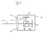
Figur 3- eine schematische Querschnittsansicht einer Kamera des erfindungsgemäßen Kamerasystems gemäß einer ersten Ausführungsform;
Figur 4- eine schematische Querschnittsansicht einer Kamera des erfindungsgemäßen Kamerasystems gemäß einer zweiten Ausführungsform; und
- Figur 5
- eine perspektivische Ansicht einer erfindungsgemäßen Stereoskopie-Kamera.
- FIG. 1
- a first embodiment of a device according to the invention;
- FIG. 2
- a second embodiment of a device according to the invention;
- FIG. 3
- a schematic cross-sectional view of a camera of the camera system according to the invention according to a first embodiment;
- FIG. 4
- a schematic cross-sectional view of a camera of the camera system according to the invention according to a second embodiment; and
- FIG. 5
- a perspective view of a stereoscopic camera according to the invention.
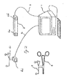
Durch die Integration der Videokamera-Funktion in das optische IR-Trackingsystem entfällt die Berechnung der aktuellen Position der Videokameras im Raum, das heißt ein zum Beispiel präkalibriertes Instrument 5 kann überprüft oder verifiziert werden, indem die von den Kameras 4a, 4b aufgenommenen Bilder im IR-Bereich zur Detektion der Marker und im sichtbaren Bereich zur Detektion der Form oder Geometrie des Instruments 5 in Relation zueinander gesetzt werden, um zum Beispiel eine Abweichung von einer vorgegebenen Instrumentenform festzustellen. Durch die Kalibrierung der Videokameras zum Beispiel bei der Herstellung des Systems erhält man die Informationen für die "virtuelle Kamera". Diese bleibt gültig, da die Position der Videokamera relativ zum Trackingsystem nach der Kalibrierung nicht mehr verändert wird. Bei einer losgelösten weiteren Videokamera 4c, wie sie in
Es wird angemerkt, dass in dem in
Mittels der Lichtquelle 9a kann zum Beispiel der Bereich vor der Kamera 4 mit Infrarot-Licht beleuchtet werden, um zum Beispiel die Detektion von reflektierenden Markern zu verbessern. Die zweite Lichtquelle 9b kann zum Beispiel Licht in einem anderen Wellenlängenbereich, wie zum Beispiel sichtbares Licht oder auch UV-Licht, aussenden, um zum Beispiel die Erfassung von Objekten durch Licht im sichtbaren Bereich zu verbessern. Jedoch kann je nach Anwendungsfall auch auf eine oder alle Beleuchtungselemente 9 verzichtet werden.By means of the
Es wird angemerkt, dass die Position der CCD-Elemente 6a und 6b in Bezug auf den halbdurchlässigen Spiegel 7 unterschiedlich sein können, das heißt die CCD-Elemente 6a und 6b können von dem Spiegel 7 unterschiedlich weit entfernt sein, da sich Licht verschiedener Wellenlängen nicht exakt auf den gleichen Punkt fokussiert. Es ist auch möglich das optische Element 8 variabel, zum Beispiel ähnlich wie bei einer an sich bekannten Foto- oder Video-kamera, auszugestalten, um je nach gewünschtem Licht-Erfassungsbereich das Licht auf den jeweiligen Sensor 6a oder 6b zu fokussieren.It is noted that the position of the CCD elements 6a and 6b with respect to the
Mittels der Recheneinheit oder CPU 14 kann zum Beispiel die Aufnahme der Bilder durch die Kameras 4a, 4b, die Einstellung der Optik 8 oder die Einstellung oder Positionierung eines Filters 5a, 5b, wie zum Beispiel Verschieben eines Filters vor einem oder mehreren der CCD-Elemente 6a, 6b, um Licht eines anderen Wellenlängenbereiches zu erfassen, gesteuert werden. Eine Synchronisation zwischen den CCD-Elementen 6a und 6b einer Kamera und den den jeweiligen CCD-Elementen 6a, 6b jeweils zugeordneten Beleuchtungselementen 9a, 9b kann ebenfalls mittels der CPU 14 erfolgen. Das Auswertungsergebnis oder auch die zum Beispiel nicht unmittelbar von der CPU 14 ausgewerteten optischen Signale können über die Verbindung 3 an ein anderes System übertragen werden.By means of the arithmetic unit or
Claims (14)
Priority Applications (3)
| Application Number | Priority Date | Filing Date | Title |
|---|---|---|---|
| DE502006007337T DE502006007337D1 (en) | 2006-12-11 | 2006-12-11 | Multi-band tracking and calibration system |
| EP06025561A EP1933276B1 (en) | 2006-12-11 | 2006-12-11 | Multiband tracking and calibration system |
| US11/954,125 US7728280B2 (en) | 2006-12-11 | 2007-12-11 | Multi-band tracking and calibration system |
Applications Claiming Priority (1)
| Application Number | Priority Date | Filing Date | Title |
|---|---|---|---|
| EP06025561A EP1933276B1 (en) | 2006-12-11 | 2006-12-11 | Multiband tracking and calibration system |
Publications (2)
| Publication Number | Publication Date |
|---|---|
| EP1933276A1 true EP1933276A1 (en) | 2008-06-18 |
| EP1933276B1 EP1933276B1 (en) | 2010-06-30 |
Family
ID=38016857
Family Applications (1)
| Application Number | Title | Priority Date | Filing Date |
|---|---|---|---|
| EP06025561A Active EP1933276B1 (en) | 2006-12-11 | 2006-12-11 | Multiband tracking and calibration system |
Country Status (3)
| Country | Link |
|---|---|
| US (1) | US7728280B2 (en) |
| EP (1) | EP1933276B1 (en) |
| DE (1) | DE502006007337D1 (en) |
Cited By (2)
| Publication number | Priority date | Publication date | Assignee | Title |
|---|---|---|---|---|
| WO2020257839A1 (en) * | 2019-06-26 | 2020-12-30 | Cortexplore Gmbh | Camera system |
| US11291507B2 (en) | 2018-07-16 | 2022-04-05 | Mako Surgical Corp. | System and method for image based registration and calibration |
Families Citing this family (31)
| Publication number | Priority date | Publication date | Assignee | Title |
|---|---|---|---|---|
| US20050088407A1 (en) | 2003-10-24 | 2005-04-28 | Matthew Bell | Method and system for managing an interactive video display system |
| US8924334B2 (en) * | 2004-08-13 | 2014-12-30 | Cae Healthcare Inc. | Method and system for generating a surgical training module |
| US9128519B1 (en) | 2005-04-15 | 2015-09-08 | Intellectual Ventures Holding 67 Llc | Method and system for state-based control of objects |
| WO2009035705A1 (en) | 2007-09-14 | 2009-03-19 | Reactrix Systems, Inc. | Processing of gesture-based user interactions |
| US8159682B2 (en) | 2007-11-12 | 2012-04-17 | Intellectual Ventures Holding 67 Llc | Lens system |
| US20100039500A1 (en) * | 2008-02-15 | 2010-02-18 | Matthew Bell | Self-Contained 3D Vision System Utilizing Stereo Camera and Patterned Illuminator |
| US8259163B2 (en) | 2008-03-07 | 2012-09-04 | Intellectual Ventures Holding 67 Llc | Display with built in 3D sensing |
| US8595218B2 (en) | 2008-06-12 | 2013-11-26 | Intellectual Ventures Holding 67 Llc | Interactive display management systems and methods |
| WO2010061293A2 (en) * | 2008-11-26 | 2010-06-03 | Haptica Limited | System and method for measuring objects viewed through a camera |
| US20100167249A1 (en) * | 2008-12-31 | 2010-07-01 | Haptica Ltd. | Surgical training simulator having augmented reality |
| US20100167253A1 (en) * | 2008-12-31 | 2010-07-01 | Haptica Ltd. | Surgical training simulator |
| US20100167250A1 (en) * | 2008-12-31 | 2010-07-01 | Haptica Ltd. | Surgical training simulator having multiple tracking systems |
| US20100167248A1 (en) * | 2008-12-31 | 2010-07-01 | Haptica Ltd. | Tracking and training system for medical procedures |
| WO2010105237A2 (en) * | 2009-03-12 | 2010-09-16 | Health Research Inc. | Method and system for minimally-invasive surgery training |
| US8657809B2 (en) * | 2010-09-29 | 2014-02-25 | Stryker Leibinger Gmbh & Co., Kg | Surgical navigation system |
| US9554763B2 (en) | 2011-10-28 | 2017-01-31 | Navigate Surgical Technologies, Inc. | Soft body automatic registration and surgical monitoring system |
| US11304777B2 (en) | 2011-10-28 | 2022-04-19 | Navigate Surgical Technologies, Inc | System and method for determining the three-dimensional location and orientation of identification markers |
| US9585721B2 (en) | 2011-10-28 | 2017-03-07 | Navigate Surgical Technologies, Inc. | System and method for real time tracking and modeling of surgical site |
| EP2615838B1 (en) * | 2012-01-12 | 2019-08-21 | SeeFront GmbH | Calibration of an autostereoscopic display system |
| US9489738B2 (en) | 2013-04-26 | 2016-11-08 | Navigate Surgical Technologies, Inc. | System and method for tracking non-visible structure of a body with multi-element fiducial |
| EP3019109B1 (en) | 2013-07-08 | 2022-09-28 | Brainlab AG | Single-marker navigation |
| WO2015022338A1 (en) * | 2013-08-13 | 2015-02-19 | Navigate Surgical Technologies, Inc. | Method for determining the location and orientation of a fiducial reference |
| CA2919170A1 (en) | 2013-08-13 | 2015-02-19 | Navigate Surgical Technologies, Inc. | System and method for focusing imaging devices |
| US20150173843A1 (en) * | 2013-12-23 | 2015-06-25 | DePuy Synthes Products, LLC | Tracking medical devices |
| JP6188603B2 (en) * | 2014-02-27 | 2017-08-30 | オリンパス株式会社 | Medical system |
| NO2944284T3 (en) * | 2014-05-13 | 2018-05-05 | ||
| JP6712994B2 (en) * | 2014-11-21 | 2020-06-24 | シンク サージカル, インコーポレイテッド | A visible light communication system for transmitting data between a visual tracking system and a tracking marker |
| US11026747B2 (en) * | 2017-04-25 | 2021-06-08 | Biosense Webster (Israel) Ltd. | Endoscopic view of invasive procedures in narrow passages |
| US11406471B1 (en) * | 2018-10-06 | 2022-08-09 | The Trustees Of Dartmouth College | Hand-held stereovision system for image updating in surgery |
| JP7286948B2 (en) * | 2018-11-07 | 2023-06-06 | ソニーグループ株式会社 | Medical observation system, signal processing device and medical observation method |
| US11730862B2 (en) | 2020-05-08 | 2023-08-22 | DePuy Synthes Products, Inc. | Identifier-based application of therapeutic coatings to medical implant devices |
Citations (8)
| Publication number | Priority date | Publication date | Assignee | Title |
|---|---|---|---|---|
| WO1996041481A1 (en) * | 1995-06-07 | 1996-12-19 | Stryker Corporation | Imaging system with independent processing of visible and infrared light energy |
| WO2001001854A2 (en) * | 1999-07-02 | 2001-01-11 | Hypermed Imaging, Inc. | Integrated imaging apparatus |
| EP1138256A2 (en) * | 2000-03-22 | 2001-10-04 | Nidek Co., Ltd. | Fundus camera with visible and invisible illumination |
| US20030135092A1 (en) * | 2002-01-15 | 2003-07-17 | Xillix Technologies Corporation | Fluorescence endoscopy video systems with no moving parts in the camera |
| US20030208125A1 (en) * | 2002-04-09 | 2003-11-06 | Rodney Dennis Watkins | Fundus Camera |
| US20040002642A1 (en) | 2002-07-01 | 2004-01-01 | Doron Dekel | Video pose tracking system and method |
| US20050285038A1 (en) * | 2002-05-22 | 2005-12-29 | Beth Israel Deaconess Medical Center | Device for wavelength-selective imaging |
| EP1667067A1 (en) | 2004-11-15 | 2006-06-07 | BrainLAB AG | Method and apparatus for calibrating a medical instrument |
Family Cites Families (12)
| Publication number | Priority date | Publication date | Assignee | Title |
|---|---|---|---|---|
| US4896673A (en) * | 1988-07-15 | 1990-01-30 | Medstone International, Inc. | Method and apparatus for stone localization using ultrasound imaging |
| CA2107062A1 (en) * | 1993-09-27 | 1995-03-28 | Ishiang Shih | Methods for wavelength determination of monochromatic light beams |
| US5923417A (en) | 1997-09-26 | 1999-07-13 | Northern Digital Incorporated | System for determining the spatial position of a target |
| US6061644A (en) | 1997-12-05 | 2000-05-09 | Northern Digital Incorporated | System for determining the spatial position and orientation of a body |
| DE19848765C2 (en) * | 1998-10-22 | 2000-12-21 | Brainlab Med Computersyst Gmbh | Position verification in camera images |
| DE19944516B4 (en) | 1999-09-16 | 2006-08-17 | Brainlab Ag | Three-dimensional shape detection with camera images |
| DE19956814B4 (en) * | 1999-11-25 | 2004-07-15 | Brainlab Ag | Shape detection of treatment devices |
| ES2204322B1 (en) | 2002-10-01 | 2005-07-16 | Consejo Sup. De Invest. Cientificas | FUNCTIONAL BROWSER. |
| DE50202566D1 (en) | 2002-10-25 | 2005-04-28 | Brainlab Ag | Apparatus and method for calibrating an element |
| CN1655592A (en) * | 2004-02-15 | 2005-08-17 | 林永全 | Photographic device employing multiple photoreceptors |
| JP5086535B2 (en) * | 2005-11-21 | 2012-11-28 | オリンパスメディカルシステムズ株式会社 | Two-plate imaging device |
| JP2007221386A (en) * | 2006-02-15 | 2007-08-30 | Eastman Kodak Co | Imaging apparatus |
-
2006
- 2006-12-11 EP EP06025561A patent/EP1933276B1/en active Active
- 2006-12-11 DE DE502006007337T patent/DE502006007337D1/en active Active
-
2007
- 2007-12-11 US US11/954,125 patent/US7728280B2/en active Active
Patent Citations (8)
| Publication number | Priority date | Publication date | Assignee | Title |
|---|---|---|---|---|
| WO1996041481A1 (en) * | 1995-06-07 | 1996-12-19 | Stryker Corporation | Imaging system with independent processing of visible and infrared light energy |
| WO2001001854A2 (en) * | 1999-07-02 | 2001-01-11 | Hypermed Imaging, Inc. | Integrated imaging apparatus |
| EP1138256A2 (en) * | 2000-03-22 | 2001-10-04 | Nidek Co., Ltd. | Fundus camera with visible and invisible illumination |
| US20030135092A1 (en) * | 2002-01-15 | 2003-07-17 | Xillix Technologies Corporation | Fluorescence endoscopy video systems with no moving parts in the camera |
| US20030208125A1 (en) * | 2002-04-09 | 2003-11-06 | Rodney Dennis Watkins | Fundus Camera |
| US20050285038A1 (en) * | 2002-05-22 | 2005-12-29 | Beth Israel Deaconess Medical Center | Device for wavelength-selective imaging |
| US20040002642A1 (en) | 2002-07-01 | 2004-01-01 | Doron Dekel | Video pose tracking system and method |
| EP1667067A1 (en) | 2004-11-15 | 2006-06-07 | BrainLAB AG | Method and apparatus for calibrating a medical instrument |
Cited By (3)
| Publication number | Priority date | Publication date | Assignee | Title |
|---|---|---|---|---|
| US11291507B2 (en) | 2018-07-16 | 2022-04-05 | Mako Surgical Corp. | System and method for image based registration and calibration |
| US11806090B2 (en) | 2018-07-16 | 2023-11-07 | Mako Surgical Corp. | System and method for image based registration and calibration |
| WO2020257839A1 (en) * | 2019-06-26 | 2020-12-30 | Cortexplore Gmbh | Camera system |
Also Published As
| Publication number | Publication date |
|---|---|
| US7728280B2 (en) | 2010-06-01 |
| DE502006007337D1 (en) | 2010-08-12 |
| EP1933276B1 (en) | 2010-06-30 |
| US20080135733A1 (en) | 2008-06-12 |
Similar Documents
| Publication | Publication Date | Title |
|---|---|---|
| EP1933276B1 (en) | Multiband tracking and calibration system | |
| EP0825826B1 (en) | Process and device for the parallel capture of visual information | |
| DE60218406T2 (en) | Ophthalmic device | |
| EP1430829B1 (en) | Ophthalmic device and measuring method | |
| EP2445387B1 (en) | Fixation control device and method for controlling the fixation of an eye | |
| DE102004061875A1 (en) | Device for diagnostic support | |
| EP2582284B1 (en) | Method and device for determining eye position | |
| DE102012200152A1 (en) | Device and method for measuring a camera | |
| DE102007017599A9 (en) | Apparatus and method for axial length measurement with extended measurement function in the anterior segment of the eye | |
| DE102015103426B4 (en) | Microscope system and method for automated alignment of a microscope | |
| US11779210B2 (en) | Ophthalmic imaging apparatus and system | |
| DE10027204B4 (en) | stereoscopic microscope | |
| DE102017110816A1 (en) | An optical observation apparatus and method for efficiently performing an automatic focusing algorithm | |
| WO2013010786A1 (en) | Device and method for recording biometric features | |
| DE19731301C2 (en) | Device for controlling a microscope by means of gaze direction analysis | |
| DE102018119343B4 (en) | Method for calibrating objects in a reference coordinate system and method for tracking objects | |
| WO2008077854A1 (en) | Ophthalmological instrument and method for determing a position of a patient's eye | |
| EP1840627A2 (en) | Method and device for determining the orientation of an eye | |
| EP2572629B1 (en) | Display device and display method | |
| DE10125971A1 (en) | Method for measuring the distance of extended objects in connection with an optical viewing device and microscope for carrying out the same | |
| EP1667067B1 (en) | Method and apparatus for calibrating a medical instrument | |
| WO2003015623A2 (en) | Method and device for obtaining images of the cornea in a non-contact manner | |
| DE102007036683B4 (en) | Apparatus and method for automatically focusing a non-mydriatic fundus camera | |
| EP2443991A1 (en) | Operation microscope with device for intra-operative refraction measurement | |
| DE102017115501B4 (en) | Technique for automatically aligning a lighting field of an ophthalmological examination device |
Legal Events
| Date | Code | Title | Description |
|---|---|---|---|
| PUAI | Public reference made under article 153(3) epc to a published international application that has entered the european phase |
Free format text: ORIGINAL CODE: 0009012 |
|
| 17P | Request for examination filed |
Effective date: 20061211 |
|
| AK | Designated contracting states |
Kind code of ref document: A1 Designated state(s): AT BE BG CH CY CZ DE DK EE ES FI FR GB GR HU IE IS IT LI LT LU LV MC NL PL PT RO SE SI SK TR |
|
| AX | Request for extension of the european patent |
Extension state: AL BA HR MK RS |
|
| 17Q | First examination report despatched |
Effective date: 20080623 |
|
| RAP1 | Party data changed (applicant data changed or rights of an application transferred) |
Owner name: BRAINLAB AG |
|
| AKX | Designation fees paid |
Designated state(s): DE FR GB IT |
|
| GRAP | Despatch of communication of intention to grant a patent |
Free format text: ORIGINAL CODE: EPIDOSNIGR1 |
|
| RIC1 | Information provided on ipc code assigned before grant |
Ipc: A61B 17/00 20060101AFI20100217BHEP Ipc: G06T 7/00 20060101ALI20100217BHEP Ipc: A61B 19/00 20060101ALI20100217BHEP |
|
| GRAS | Grant fee paid |
Free format text: ORIGINAL CODE: EPIDOSNIGR3 |
|
| GRAA | (expected) grant |
Free format text: ORIGINAL CODE: 0009210 |
|
| AK | Designated contracting states |
Kind code of ref document: B1 Designated state(s): DE FR GB IT |
|
| REG | Reference to a national code |
Ref country code: GB Ref legal event code: FG4D Free format text: NOT ENGLISH |
|
| REF | Corresponds to: |
Ref document number: 502006007337 Country of ref document: DE Date of ref document: 20100812 Kind code of ref document: P |
|
| PG25 | Lapsed in a contracting state [announced via postgrant information from national office to epo] |
Ref country code: IT Free format text: LAPSE BECAUSE OF FAILURE TO SUBMIT A TRANSLATION OF THE DESCRIPTION OR TO PAY THE FEE WITHIN THE PRESCRIBED TIME-LIMIT Effective date: 20100630 |
|
| PLBE | No opposition filed within time limit |
Free format text: ORIGINAL CODE: 0009261 |
|
| STAA | Information on the status of an ep patent application or granted ep patent |
Free format text: STATUS: NO OPPOSITION FILED WITHIN TIME LIMIT |
|
| 26N | No opposition filed |
Effective date: 20110331 |
|
| REG | Reference to a national code |
Ref country code: DE Ref legal event code: R097 Ref document number: 502006007337 Country of ref document: DE Effective date: 20110330 |
|
| GBPC | Gb: european patent ceased through non-payment of renewal fee |
Effective date: 20101211 |
|
| PG25 | Lapsed in a contracting state [announced via postgrant information from national office to epo] |
Ref country code: GB Free format text: LAPSE BECAUSE OF NON-PAYMENT OF DUE FEES Effective date: 20101211 |
|
| REG | Reference to a national code |
Ref country code: DE Ref legal event code: R082 Ref document number: 502006007337 Country of ref document: DE Representative=s name: SCHWABE SANDMAIR MARX, DE |
|
| REG | Reference to a national code |
Ref country code: DE Ref legal event code: R082 Ref document number: 502006007337 Country of ref document: DE Representative=s name: SCHWABE SANDMAIR MARX, DE Effective date: 20131104 Ref country code: DE Ref legal event code: R081 Ref document number: 502006007337 Country of ref document: DE Owner name: BRAINLAB AG, DE Free format text: FORMER OWNER: BRAINLAB AG, 85622 FELDKIRCHEN, DE Effective date: 20131104 Ref country code: DE Ref legal event code: R082 Ref document number: 502006007337 Country of ref document: DE Representative=s name: SCHWABE SANDMAIR MARX PATENTANWAELTE RECHTSANW, DE Effective date: 20131104 |
|
| REG | Reference to a national code |
Ref country code: FR Ref legal event code: PLFP Year of fee payment: 10 |
|
| REG | Reference to a national code |
Ref country code: FR Ref legal event code: PLFP Year of fee payment: 11 |
|
| REG | Reference to a national code |
Ref country code: DE Ref legal event code: R082 Ref document number: 502006007337 Country of ref document: DE Representative=s name: SCHWABE SANDMAIR MARX PATENTANWAELTE RECHTSANW, DE Ref country code: DE Ref legal event code: R081 Ref document number: 502006007337 Country of ref document: DE Owner name: BRAINLAB AG, DE Free format text: FORMER OWNER: BRAINLAB AG, 85622 FELDKIRCHEN, DE Ref country code: DE Ref legal event code: R082 Ref document number: 502006007337 Country of ref document: DE Representative=s name: SSM SANDMAIR PATENTANWAELTE RECHTSANWALT PARTN, DE |
|
| REG | Reference to a national code |
Ref country code: FR Ref legal event code: CA Effective date: 20170706 |
|
| REG | Reference to a national code |
Ref country code: FR Ref legal event code: PLFP Year of fee payment: 12 |
|
| P01 | Opt-out of the competence of the unified patent court (upc) registered |
Effective date: 20230508 |
|
| PGFP | Annual fee paid to national office [announced via postgrant information from national office to epo] |
Ref country code: FR Payment date: 20231221 Year of fee payment: 18 Ref country code: DE Payment date: 20231214 Year of fee payment: 18 |