EP1926444B1 - Vertebral fixing system - Google Patents
Vertebral fixing system Download PDFInfo
- Publication number
- EP1926444B1 EP1926444B1 EP06831187A EP06831187A EP1926444B1 EP 1926444 B1 EP1926444 B1 EP 1926444B1 EP 06831187 A EP06831187 A EP 06831187A EP 06831187 A EP06831187 A EP 06831187A EP 1926444 B1 EP1926444 B1 EP 1926444B1
- Authority
- EP
- European Patent Office
- Prior art keywords
- connecting part
- ligature
- rod
- passageway
- link
- Prior art date
- Legal status (The legal status is an assumption and is not a legal conclusion. Google has not performed a legal analysis and makes no representation as to the accuracy of the status listed.)
- Active
Links
Images


Classifications
-
- A—HUMAN NECESSITIES
- A61—MEDICAL OR VETERINARY SCIENCE; HYGIENE
- A61B—DIAGNOSIS; SURGERY; IDENTIFICATION
- A61B17/00—Surgical instruments, devices or methods, e.g. tourniquets
- A61B17/56—Surgical instruments or methods for treatment of bones or joints; Devices specially adapted therefor
- A61B17/58—Surgical instruments or methods for treatment of bones or joints; Devices specially adapted therefor for osteosynthesis, e.g. bone plates, screws, setting implements or the like
- A61B17/68—Internal fixation devices, including fasteners and spinal fixators, even if a part thereof projects from the skin
- A61B17/70—Spinal positioners or stabilisers ; Bone stabilisers comprising fluid filler in an implant
- A61B17/7053—Spinal positioners or stabilisers ; Bone stabilisers comprising fluid filler in an implant with parts attached to bones or to each other by flexible wires, straps, sutures or cables
-
- A—HUMAN NECESSITIES
- A61—MEDICAL OR VETERINARY SCIENCE; HYGIENE
- A61B—DIAGNOSIS; SURGERY; IDENTIFICATION
- A61B17/00—Surgical instruments, devices or methods, e.g. tourniquets
- A61B17/56—Surgical instruments or methods for treatment of bones or joints; Devices specially adapted therefor
- A61B17/58—Surgical instruments or methods for treatment of bones or joints; Devices specially adapted therefor for osteosynthesis, e.g. bone plates, screws, setting implements or the like
- A61B17/68—Internal fixation devices, including fasteners and spinal fixators, even if a part thereof projects from the skin
- A61B17/70—Spinal positioners or stabilisers ; Bone stabilisers comprising fluid filler in an implant
- A61B17/7062—Devices acting on, attached to, or simulating the effect of, vertebral processes, vertebral facets or ribs ; Tools for such devices
- A61B17/707—Devices acting on, or attached to, a transverse process or rib; Tools therefor
-
- A—HUMAN NECESSITIES
- A61—MEDICAL OR VETERINARY SCIENCE; HYGIENE
- A61B—DIAGNOSIS; SURGERY; IDENTIFICATION
- A61B17/00—Surgical instruments, devices or methods, e.g. tourniquets
- A61B17/56—Surgical instruments or methods for treatment of bones or joints; Devices specially adapted therefor
- A61B17/58—Surgical instruments or methods for treatment of bones or joints; Devices specially adapted therefor for osteosynthesis, e.g. bone plates, screws, setting implements or the like
- A61B17/68—Internal fixation devices, including fasteners and spinal fixators, even if a part thereof projects from the skin
- A61B17/70—Spinal positioners or stabilisers ; Bone stabilisers comprising fluid filler in an implant
- A61B17/7001—Screws or hooks combined with longitudinal elements which do not contact vertebrae
- A61B17/7032—Screws or hooks with U-shaped head or back through which longitudinal rods pass
-
- A—HUMAN NECESSITIES
- A61—MEDICAL OR VETERINARY SCIENCE; HYGIENE
- A61B—DIAGNOSIS; SURGERY; IDENTIFICATION
- A61B17/00—Surgical instruments, devices or methods, e.g. tourniquets
- A61B17/56—Surgical instruments or methods for treatment of bones or joints; Devices specially adapted therefor
- A61B17/58—Surgical instruments or methods for treatment of bones or joints; Devices specially adapted therefor for osteosynthesis, e.g. bone plates, screws, setting implements or the like
- A61B17/68—Internal fixation devices, including fasteners and spinal fixators, even if a part thereof projects from the skin
- A61B17/70—Spinal positioners or stabilisers ; Bone stabilisers comprising fluid filler in an implant
- A61B17/7001—Screws or hooks combined with longitudinal elements which do not contact vertebrae
- A61B17/7041—Screws or hooks combined with longitudinal elements which do not contact vertebrae with single longitudinal rod offset laterally from single row of screws or hooks
Definitions
- the present invention relates to a vertebral fixation system that can be mounted on a vertebra.
- One field of application envisaged is in particular, but not exclusively, the treatment of scoliosis or, more generally, corrections of abnormal curvatures of the spine.
- the spine is formed by the superposition of vertebrae, normally aligned along a vertebral axis, from the lumbar to the cervical and each having a posterior wall from which the spinous process protrudes and two lateral edges of the walls from which the ribs protrude and / or transverse processes.
- vertebrae When the spine of an individual has an abnormal curvature, the vertebrae are inclined relative to each other and relative to said vertebral axis.
- the lateral edges of the vertebrae on the same side are thus close to each other and form a concavity while the lateral edges of the other side appear distant from each other and form a convexity.
- the lateral edges of the vertebrae of the concave side are spaced from each other and carried relative to each other at a distance substantially equivalent to that which separates the lateral edges of the other side.
- known devices include screws that are inserted into the vertebrae or hooks that are introduced along the inner wall of the spinal canal and rods for connecting the screws or hooks.
- the hooks are usually inserted two by two in each vertebra and on each side near the pedicles, their head protruding from the posterior wall of the vertebra, one on each side of the spinous process.
- the tulip heads for example, are likely to receive a rod which is locked by means of a nut screwed onto the head and resting on the rod.
- the rows formed by the hook heads located on each side of the spinous processes are interconnected and held in a fixed position by two rods parallel to each other and to the axis of the spine.
- screws reduces the risk of the intervention. They also present tulip-shaped heads and are inserted two by two on the posterior wall of the vertebrae in the pedicles on either side of the spinous process. Thus, the screws are attachment points in the vertebrae to maintain them relative to each other. However, they are necessarily introduced into the pedicle of the vertebrae which, under certain circumstances, is small or deteriorated.
- An object of the present invention is to provide a spinal fixation system which makes it possible to avoid the drawbacks mentioned above and to ensure controlled locking of the link.
- said locking means can take a first position with respect to the connecting piece in which two link portions are free in said path (s) of passage, a second position relative to the connecting piece in which the two link portions are immobilized in translation relative to the connecting piece and positions intermediates in which a coefficient of friction is created between said link portions and said connecting piece.
- the two portions of the link which are on both sides of the transverse process are both arranged in one or more paths, when the locking means are brought into their position of blocking, the two portions of the link can exert the tension necessary for fixing the vertebra, via a dimension and / or part of the posterior arch of a vertebra and / or an apophysis transverse.
- the "dimensions" of the passageway or paths can be defined with precision in the various phases of clamping and blocking the link.
- the connecting piece defines a single passage path and the two link portions are engaged in the single passage path.
- the single passageway is defined on the one hand by the outer surface of the part of the rod engaged in the connecting piece and on the other hand by a wall of the connecting piece and the locking means are able to modify the section of the way of passage.
- the connecting piece comprises two longitudinal elements whose first ends are hinged together, the longitudinal elements each having a recess adapted to receive a portion of a section of said rod, the wall of said recess. defining with the lateral surface of the rod, the passageway or the passageways for the link portions, the locking means being mounted at the second ends of the longitudinal elements.
- the connecting piece comprises a part having the general shape of a U adapted to receive said rod and whose outer ends of the legs of the U are threaded and in that the adjustable locking means comprise a threaded ring adapted to cooperate with the thread of the U-shaped part, the screwing of the ring causing the clamping of the branches of the workpiece on the rod.
- said passageway or paths is (are) constituted (s) by the space between the inner wall of the recess formed in said connecting piece and the side wall of said rod.
- the longitudinal elements 20 and 22 are articulated with respect to one another at their second ends 20b, 22b about a pivot axis 24.
- the locking means are constituted by a screw 26 whose head 26a is engaged in a hole 28 formed at the first end 22a of the longitudinal member 22.
- the first end 20a of the longitudinal member 20 is pierced with a threaded bore 28 for cooperating with the threaded body 26b of the screw 26.
- Each longitudinal member 20, 22 has an outer face 20c, 22c and an inner face 20d, 22d.
- the longitudinal elements 20 and 22 are mounted such that the inner faces 20d, 22d of the longitudinal elements are facing one another.
- the inner faces 20d, 22d of the longitudinal elements 20 and 22 have recesses 30 and 32 respectively facing each other which have a substantially semi-cylindrical shape.
- the recesses 30 and 32 define walls 34 and 36 which are regulated surfaces whose generatrices are parallel to the pivot axis 24. Finally, slots 38 and 40 communicate the bottom of the recesses 30 and 32 with the external faces 20c. and 22c longitudinal elements 20 and 22. As will be explained in more detail later, the recesses 30 and 32 are intended to receive the rod 18 and a portion of the link 14, the slots 38 and 40 being intended to pass link 14.
- FIGS. 2A to 2C we will explain the use of the fastening system.
- the longitudinal elements 20 and 22 are shown in the spaced-apart position, in which position, of course, the locking means 16 are not active, the threaded body 26b of the screw 26 not being engaged in the hole 28.
- the link 14 is engaged in the slots 38 and 40 of the longitudinal elements against a portion of the inner wall 34, 36 of the recesses 30 and 32.
- the screw 18 is introduced into the recess 30 of the longitudinal element 20 so that the two portions 42 and 44 of the link 14 are arranged between the inner wall of the recesses 30 and 32 and the lateral face 18a. of the rod 18.
- These two surfaces define a passageway 46 for the link 14 in which are arranged the portions 42 and 44 of the link 14.
- the portions 42 and 44 of the link define for this link 14 a loop portion 48 which extends beyond the outer face 20c of the longitudinal member 20 and two free portions 50 and 52 which extend out of the 22c outer face of the longitudinal member 22.
- the link 14 can slide freely in the passageway 46.
- the two portions 42 and 44 of the link are arranged in the recesses 30 and 32 on the same side of the rod 18. This arrangement makes it possible to obtain an optimal result. However, it would not depart from the invention if the portions 42 and 44 of the link 14 were disposed on either side of the rod 18. In this case, it should be considered that the outer face 18a of the rod 18 and the internal walls of the recesses 30 and 32 define two paths respectively for the portions 42 and 44 of the link 14.
- the connecting piece 12 ' is constituted by a part 50 having the general shape of a U.
- the inner wall of this part consists of a bottom 52 of substantially semi-cylindrical shape and two portions substantially planar 54 and 56 which correspond to the two branches of the part 50.
- the width I of the recess 58 formed in the part 50 is substantially equal to the diameter d of the rod 18.
- On its outer face 50a which is of revolution around a longitudinal axis of the part 50 is formed at its upper part a thread 60.
- the thread 60 is disposed entirely above the rod 18 when it is placed in the housing 58.
- the thread 60 is intended for cooperate with a clamping ring 62 which constitutes the adjustable locking means.
- This ring has a slightly frustoconical recess 64 whose lateral face 66 has a tapping 68.
- the ring 62 when fully screwed onto the threaded portion 60 of the part 50, causes an elastic deformation of the branches of the part 50 ensuring as will be explained later the pinching and tightening portions of the link 14 between the rod 18 and the or the inner wall of the housing 58.
- the piece 50 has in its bottom 70 a passage 72 to allow the passage of the link 14 as will be explained later.
- FIG. 7A two different modes of implementation of the flexible link 14 will be described inside the connecting piece 12 'according to the second embodiment.
- the side wall of the rod 18 and the inner wall of the housing 58 of the part 50 potentially define two passageways 74 and 76 for the median portions of the flexible link 14.
- FIG. Figure 7A only passage 74 is used.
- the two intermediate portions 42 and 44 of the flexible link 14 are arranged in the passage 74. This arrangement has all the advantages that have been described in connection with the first embodiment.
- the medial portions 42 and 44 of the flexible link 14 are respectively disposed in the passageways 76 and 78, that is to say on either side of the rod 18.
- This embodiment also has all the advantages described in connection with the first embodiment of the device since the free ends 50 and 52 of the link 14 are accessible to exert the desired traction to obtain a suitable clamping on the spinous process before locking the clamping ring 62 on the room 52.
- This second embodiment has the advantage of being simpler in its design since it makes it possible to avoid, in particular, the production of the two longitudinal parts constituting a kind of clamp hinged about the axis 24.
- the locking means are constituted by a separate element of the connecting piece and removable relative thereto.
- the locking means cooperate by screwing with the connecting piece. It is thus possible to precisely adjust the dimensions of the passageway or paths defined by the connecting piece and the rod in which or in which the link passes.
- the initial phase it is possible to adjust the coefficient of friction between the link on the one hand and the rod and the connecting piece on the other hand.
- the final phase a very effective tightening of the connection between the rod and the locking piece is obtained.
Abstract
Description
La présente invention concerne un système de fixation vertébrale susceptible d'être monté sur une vertèbre.The present invention relates to a vertebral fixation system that can be mounted on a vertebra.
Un domaine d'application envisagé est notamment, mais non exclusivement, le traitement des scolioses ou, plus généralement des corrections de courbures anormales du rachis.One field of application envisaged is in particular, but not exclusively, the treatment of scoliosis or, more generally, corrections of abnormal curvatures of the spine.
Le rachis est formé par la superposition de vertèbres, normalement alignées selon un axe vertébral, des lombaires jusqu'aux cervicales et chacune présentant une paroi postérieure de laquelle fait saillie l'apophyse épineuse et deux bords latéraux des parois desquels font saillies les côtes et/ou les apophyses transverses. Lorsque le rachis d'un individu présente une courbure anormale, les vertèbres sont inclinées les unes par rapport aux autres et par rapport audit axe vertébral. Les bords latéraux des vertèbres situés d'un même côté sont ainsi rapprochés les uns des autres et forment une concavité alors que les bords latéraux de l'autre côté apparaissent éloignés les uns des autres et forment une convexité.The spine is formed by the superposition of vertebrae, normally aligned along a vertebral axis, from the lumbar to the cervical and each having a posterior wall from which the spinous process protrudes and two lateral edges of the walls from which the ribs protrude and / or transverse processes. When the spine of an individual has an abnormal curvature, the vertebrae are inclined relative to each other and relative to said vertebral axis. The lateral edges of the vertebrae on the same side are thus close to each other and form a concavity while the lateral edges of the other side appear distant from each other and form a convexity.
Afin de redresser la colonne vertébrale, les bords latéraux des vertèbres du côté concave sont éloignés les uns des autres et portés les uns par rapport aux autres à une distance sensiblement équivalente à celle qui sépare les bords latéraux de l'autre côté. Pour maintenir ensuite les vertèbres les unes par rapport aux autres, des dispositifs connus comprennent des vis que l'on insère dans les vertèbres ou des crochets que l'on introduit le long de la paroi interne du canal rachidien et des tiges destinées à relier les vis ou les crochets.In order to straighten the spine, the lateral edges of the vertebrae of the concave side are spaced from each other and carried relative to each other at a distance substantially equivalent to that which separates the lateral edges of the other side. To then maintain the vertebrae relative to each other, known devices include screws that are inserted into the vertebrae or hooks that are introduced along the inner wall of the spinal canal and rods for connecting the screws or hooks.
Les crochets sont généralement introduits deux par deux dans chaque vertèbre et de chaque côté à proximité des pédicules, leur tête faisant saillie de la paroi postérieure de la vertèbre, une de chaque côté de l'apophyse épineuse. Les têtes formant tulipe, par exemple, sont susceptibles de recevoir une tige qui est bloquée au moyen d'un écrou vissé sur la tête et en appui sur la tige. Les rangées constituées par les têtes de crochet situées de chaque côté des apophyses épineuses sont reliées entre elles et maintenues en position fixe par deux tiges parallèles entre elles et à l'axe du rachis.The hooks are usually inserted two by two in each vertebra and on each side near the pedicles, their head protruding from the posterior wall of the vertebra, one on each side of the spinous process. The tulip heads, for example, are likely to receive a rod which is locked by means of a nut screwed onto the head and resting on the rod. The rows formed by the hook heads located on each side of the spinous processes are interconnected and held in a fixed position by two rods parallel to each other and to the axis of the spine.
Cependant, l'utilisation de ces crochets est délicate puisque l'opérateur ne doit en aucun cas affecter la moelle épinière qui s'étend au centre du canal rachidien, sous peine de provoquer une paralysie du patient.However, the use of these hooks is tricky since the operator must in no way affect the spinal cord which extends to the center of the spinal canal, otherwise the patient will be paralyzed.
L'utilisation des vis permet de diminuer les risques de l'intervention. Elles présentent également des têtes formant tulipe et sont insérées, deux par deux sur la paroi postérieure des vertèbres dans les pédicules de chaque côté de l'apophyse épineuse. Ainsi, les vis constituent des points de fixation dans les vertèbres pour les maintenir les unes par rapport aux autres. Cependant, elles sont nécessairement introduites dans le pédicule des vertèbres qui, dans certaines circonstances, est de faible taille ou détérioré.The use of screws reduces the risk of the intervention. They also present tulip-shaped heads and are inserted two by two on the posterior wall of the vertebrae in the pedicles on either side of the spinous process. Thus, the screws are attachment points in the vertebrae to maintain them relative to each other. However, they are necessarily introduced into the pedicle of the vertebrae which, under certain circumstances, is small or deteriorated.
Un problème qui se pose et que vise à résoudre la présente invention, est alors de constituer des points de fixation, lorsqu'il n'est pas possible d'introduire de vis dans les vertèbres de la portion incurvée et que l'utilisation des crochets s'avère trop dangereuse. Dans la demande de brevet
Ce système de fixation vertébrale susceptible d'être monté sur une vertèbre du rachis pour la relier à une tige comprend :
- une pièce de liaison disposée au regard de ladite côte et/ou de ladite apophyse transverse, susceptible d'être reliée à ladite tige;
- un lien flexible de forme allongée susceptible de relier ensemble ladite pièce de liaison et au moins une côte et/ou une apophyse transverse ; et
- des moyens de blocage réglables solidaires de ladite pièce de liaison, ledit lien présentant une première extrémité solidaire de ladite pièce de liaison et une seconde extrémité libre susceptible de coulisser dans ladite pièce de liaison en formant une boucle, lesdits moyens de blocage étant susceptibles de maintenir en position fixe, simultanément, ladite pièce de liaison par rapport à ladite tige et une portion dudit lien comprise entre lesdites extrémités étant susceptible d'être bloquée en translation par rapport à ladite pièce de liaison par lesdits moyens de blocage réglables, par quoi la boucle présente une longueur déterminée de façon à bloquer le déplacement relatif de ladite tige et de ladite vertèbre dans des directions opposées l'une de l'autre.
- a connecting piece disposed opposite said rib and / or said transverse process, capable of being connected to said rod;
- a flexible link of elongated shape capable of connecting together said connecting piece and at least one rib and / or a transverse process; and
- adjustable locking means secured to said connecting piece, said link having a first end secured to said connecting piece and a second free end slidable in said connecting piece forming a loop, said locking means being able to maintain in a fixed position, simultaneously, said connecting piece with respect to said rod and a portion of said link between said ends being capable of being locked in translation relative to said connecting piece by said adjustable locking means, whereby the loop has a determined length so as to block the relative displacement of said rod and said vertebra in opposite directions from one another.
Ce système est satisfaisant mais il peut présenter dans certains cas l'inconvénient suivant. Lorsque le chirurgien exerce une traction sur l'extrémité libre du lien flexible, celui-ci peut être coincé par frottement sur la face inférieure de l'apophyse. Dans ce cas, on comprend que si la portion du lien entre la face inférieure de l'apophyse et la zone de traction sur le lien est effectivement sous tension, la partie qui s'étend entre l'extrémité du lien solidaire de la pièce allongée et la face inférieure de l'apophyse n'est pas sous tension. Il en résulte donc que globalement le lien n'exerce pas convenablement sa fonction de solidarisation avec la vertèbre.This system is satisfactory but it may present in some cases the following disadvantage. When the surgeon pulls on the free end of the flexible link, it can be frictionally stuck on the underside of the process. In this case, it is understood that if the portion of the link between the lower face of the process and the traction zone on the link is effectively under tension, the portion that extends between the end of the integral link of the elongate piece and the underside of the process is not energized. As a result, overall, the link does not properly fulfill its function of joining the vertebra.
Un objet de la présente invention est de fournir un système de fixation vertébrale qui permet d'éviter les inconvénients cités ci-dessus et d'assurer un blocage contrôlé du lien.An object of the present invention is to provide a spinal fixation system which makes it possible to avoid the drawbacks mentioned above and to ensure controlled locking of the link.
Pour atteindre ce but selon l'invention, le système de fixation vertébrale susceptible d'être monté sur une vertèbre du rachis pour la relier à une tige comprend :
- une pièce de liaison présentant un premier et un deuxième côté, susceptible d'être reliée à ladite tige,
- un lien flexible de forme allongée susceptible de relier ensemble ladite pièce de liaison et au moins une côte et/ou une apophyse transverse et/ou une partie de l'arc postérieur d'une vertèbre ; et
- des moyens de blocage réglables montés sur ladite pièce de liaison, lesdits moyens de blocage étant distincts de ladite pièce de liaison et coopérant avec celle-ci par vissage,
- ledit lien présente deux extrémités libres ;
- ladite pièce de liaison définit au moins un chemin de passage pour ledit lien de telle manière que deux portions distinctes dudit lien puissent être engagées dans ledit chemin de passage ou lesdits chemins de passage de telle manière que lesdites deux portions de lien définissent une première partie de lien formant une boucle s'étendant d'un premier côté de ladite pièce de liaison et des deuxième et troisième parties de lien s'étendant de l'autre côté de ladite pièce de liaison respectivement entre une desdites portions de lien et une desdites extrémités libres ; et
- a connecting piece having a first and a second side, connectable to said rod,
- a flexible link of elongated shape capable of connecting together said connecting piece and at least one rib and / or a transverse process and / or a portion of the posterior arc of a vertebra; and
- adjustable locking means mounted on said connecting piece, said locking means being separate from said connecting piece and cooperating with it by screwing,
- said link has two free ends;
- said connecting piece defines at least one passage path for said link in such a way that two distinct portions of said link can be engaged in said passage path or said passage paths in such a way that said two link portions define a first part of loop forming link extending from a first side of said connecting piece and second and third link portions extending from the other side of said connecting piece respectively between one of said link portions and one of said free ends ; and
- lesdits moyens de blocage peuvent prendre une première position par rapport à la pièce de liaison dans laquelle les deux portions de lien sont libres dans ledit ou lesdits chemin(s) de passage, une deuxième position par rapport à la pièce de liaison dans laquelle les deux portions de lien sont immobilisées en translation par rapport à la pièce de liaison et des positions intermédiaires dans lesquelles un coefficient de frottement est créé entre lesdites portions de lien et ladite pièce de liaison.said locking means can take a first position with respect to the connecting piece in which two link portions are free in said path (s) of passage, a second position relative to the connecting piece in which the two link portions are immobilized in translation relative to the connecting piece and positions intermediates in which a coefficient of friction is created between said link portions and said connecting piece.
On comprend que grâce au fait que les deux portions du lien qui se trouvent de part et d'autre de l'apophyse transverse sont toutes les deux disposées dans un ou plusieurs chemins de passage, lorsque les moyens de blocage sont amenés dans leur position de blocage, les deux portions du lien peuvent exercer la tension nécessaire à la fixation de la vertèbre, par l'intermédiaire d'une cote et/ou d'une partie de l'arc postérieur d'une vertèbre et/ou d'une apophyse transverse.It is understood that because the two portions of the link which are on both sides of the transverse process are both arranged in one or more paths, when the locking means are brought into their position of blocking, the two portions of the link can exert the tension necessary for fixing the vertebra, via a dimension and / or part of the posterior arch of a vertebra and / or an apophysis transverse.
En outre, comme les moyens de blocage coopèrent par vissage avec la pièce de liaison, les "dimensions" du ou des chemins de passage peuvent être définies avec précision dans les différentes phases du serrage puis du blocage du lien.In addition, as the locking means cooperate by screwing with the connecting piece, the "dimensions" of the passageway or paths can be defined with precision in the various phases of clamping and blocking the link.
De préférence, la pièce de liaison définit un unique chemin de passage et les deux portions de lien sont engagées dans le chemin de passage unique.Preferably, the connecting piece defines a single passage path and the two link portions are engaged in the single passage path.
De préférence également, le chemin de passage unique est défini d'une part par la surface externe de la partie de la tige engagée dans la pièce de liaison et d'autre part par une paroi de la pièce de liaison et les moyens de blocage sont aptes à modifier la section du chemin de passage.Also preferably, the single passageway is defined on the one hand by the outer surface of the part of the rod engaged in the connecting piece and on the other hand by a wall of the connecting piece and the locking means are able to modify the section of the way of passage.
On obtient ainsi, lorsque les moyens de blocage sont dans leur deuxième position, un serrage effectif des deux portions du lien qui entraîne leur immobilisation.Thus, when the locking means are in their second position, an effective clamping of the two portions of the link which causes their immobilization.
Selon un premier mode de mise en oeuvre, la pièce de liaison comprend deux éléments longitudinaux dont les premières extrémités sont articulées entre elles, les éléments longitudinaux présentant chacun un évidement apte à recevoir une partie d'une section de ladite tige, la paroi dudit évidement définissant avec la surface latérale de la tige, le chemin de passage ou les chemins de passage pour les portions de lien, les moyens de blocage étant montés aux deuxièmes extrémités des éléments longitudinaux.According to a first embodiment, the connecting piece comprises two longitudinal elements whose first ends are hinged together, the longitudinal elements each having a recess adapted to receive a portion of a section of said rod, the wall of said recess. defining with the lateral surface of the rod, the passageway or the passageways for the link portions, the locking means being mounted at the second ends of the longitudinal elements.
Selon un deuxième mode de mise en oeuvre, la pièce de liaison comprend une pièce ayant la forme générale d'un U apte à recevoir ladite tige et dont les extrémités externes des branches du U sont filetées et en ce que les moyens de blocage réglables comprennent une bague taraudée apte à coopérer avec le filetage de la pièce en U, le vissage de la bague provoquant le serrage des branches de la pièce sur la tige.According to a second embodiment, the connecting piece comprises a part having the general shape of a U adapted to receive said rod and whose outer ends of the legs of the U are threaded and in that the adjustable locking means comprise a threaded ring adapted to cooperate with the thread of the U-shaped part, the screwing of the ring causing the clamping of the branches of the workpiece on the rod.
De préférence, le ou lesdits chemins de passage est (sont) constitué(s) par l'espace entre la paroi interne de l'évidement ménagé dans ladite pièce de liaison et la paroi latérale de ladite tige.Preferably, said passageway or paths is (are) constituted (s) by the space between the inner wall of the recess formed in said connecting piece and the side wall of said rod.
D'autres caractéristiques et avantages de l'invention apparaîtront mieux à la lecture de la description qui suit de plusieurs modes de réalisation de l'invention donnés à titre d'exemple non limitatif. La description se réfère aux figures annexées sur lesquelles :
- la
figure 1 est une vue en perspective du système de fixation vertébrale selon un premier mode de réalisation ; - les
figures 2A, 2B et 2C sont des vues en coupe verticale du système de fixation illustrant l'utilisation dudit système représenté sur lafigure 1 ; - la
figure 3 est une vue de face montrant le système de fixation de lafigure 1 mis en place sur une vertèbre ; - la
figure 4 est une vue en perspective d'un deuxième mode de réalisation du système de fixation, le lien n'étant pas représenté ; - la
figure 5 est une vue éclatée du dispositif de liaison de lafigure 4 ; - la
figure 6 est une vue de dessus d'une partie du dispositif de liaison de lafigure 5 ; - la
figure 6A est une vue en coupe selon la ligne AA de lafigure 6 ; - la
figure 7 est une vue de face du système de fixation selon le deuxième mode de réalisation ; et - les
figures 7A et 7B sont des vues en coupe selon la ligne VII-VII de lafigure 7 illustrant deux modes de mise en place du lien souple.
- the
figure 1 is a perspective view of the vertebral fixation system according to a first embodiment; - the
FIGS. 2A, 2B and 2C are vertical sectional views of the fastening system illustrating the use of said system shown in FIG.figure 1 ; - the
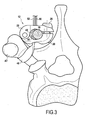
figure 3 is a front view showing the fastening system of thefigure 1 set up on a vertebra; - the
figure 4 is a perspective view of a second embodiment of the fastening system, the link not being shown; - the
figure 5 is an exploded view of the link device of thefigure 4 ; - the
figure 6 is a view from above of a part of the connecting device of thefigure 5 ; - the
Figure 6A is a sectional view along line AA of thefigure 6 ; - the
figure 7 is a front view of the fastening system according to the second embodiment; and - the
Figures 7A and 7B are sectional views along line VII-VII of thefigure 7 illustrating two modes of implementation of the flexible link.
Comme le montre la
Comme on le voit mieux sur la
Dans le mode de réalisation considéré, les moyens de blocage sont constitués par une vis 26 dont la tête 26a est engagée dans un trou 28 réalisé à la première extrémité 22a de l'élément longitudinal 22. La première extrémité 20a de l'élément longitudinal 20 est percée d'un alésage taraudé 28 destiné à coopérer avec le corps fileté 26b de la vis 26. Chaque élément longitudinal 20, 22 comporte une face externe 20c, 22c et une face interne 20d, 22d. Les éléments longitudinaux 20 et 22 sont montés de telle manière que les faces internes 20d, 22d des éléments longitudinaux soient en regard l'une de l'autre. Les faces internes 20d, 22d des éléments longitudinaux 20 et 22 comportent des évidements respectivement 30 et 32 en regard l'un de l'autre qui ont une forme sensiblement semi-cylindrique. Les évidements 30 et 32 définissent des parois 34 et 36 qui sont des surfaces réglées dont les génératrices sont parallèles à l'axe de pivotement 24. Enfin, des fentes 38 et 40 font communiquer le fond des évidements 30 et 32 avec les faces externes 20c et 22c des éléments longitudinaux 20 et 22. Comme on l'expliquera plus en détail ultérieurement, les évidements 30 et 32 sont destinés à recevoir la tige 18 ainsi qu'une portion du lien 14, les fentes 38 et 40 étant destinées à laisser passer le lien 14.In the embodiment considered, the locking means are constituted by a
En se référant aux
Sur la
Comme le montre mieux la
Dans cette position de blocage, on obtient donc la solidarisation de la tige 18 et du lien 14 par l'intermédiaire de la pièce de liaison 12.In this blocking position, the
On comprend également que du fait que le chirurgien exerce une traction sur les deux extrémités libres 50 et 52 du lien 14, on s'affranchit des risques de coincement entre le lien 14 et la face inférieure de l'apophyse transverse ou de la cote, ce qui garantit une solidarisation effective sur l'apophyse transverse ou la cote ou encore une partie de l'arc postérieur d'une vertèbre.It is also understood that because the surgeon pulls on the two
C'est ce qui est représenté sur la
Dans la description précédente, les deux portions 42 et 44 du lien sont disposées dans les évidements 30 et 32 d'un même côté de la tige 18. Cette disposition permet d'obtenir un résultat optimal. Cependant, on ne sortirait pas de l'invention si les portions 42 et 44 du lien 14 étaient disposées de part et d'autre de la tige 18. Dans ce cas, il faudrait considérer que la face externe 18a de la tige 18 et les parois internes des évidements 30 et 32 définissent deux chemins de passage respectivement pour les portions 42 et 44 du lien 14.In the preceding description, the two
Sur les
Sur ces figures, on retrouve la tige 18, la pièce de liaison qui porte la référence 12' et le lien souple 14.In these figures, there is the
Dans ce deuxième mode de réalisation, la pièce de liaison 12' est constituée par une pièce 50 ayant la forme générale d'un U. La paroi interne de cette pièce est constituée par un fond 52 de forme sensiblement semi-cylindrique et par deux portions sensiblement planes 54 et 56 qui correspondent aux deux branches de la pièce 50. La largeur I de l'évidement 58 ménagé dans la pièce 50 est sensiblement égale au diamètre d de la tige 18. Sur sa face externe 50a qui est de révolution autour d'un axe longitudinal de la pièce 50 est réalisé à sa partie supérieure un filetage 60. Le filetage 60 est disposé entièrement au-dessus de la tige 18 lorsque celle-ci est mise en place dans le logement 58. Le filetage 60 est destiné à coopérer avec une bague de serrage 62 qui constitue les moyens de blocage réglables. Cette bague comporte un évidement légèrement tronconique 64 dont la face latérale 66 comporte un taraudage 68.In this second embodiment, the connecting piece 12 'is constituted by a
On comprend dès à présent que la bague 62, lorsqu'elle est entièrement vissée sur la partie filetée 60 de la pièce 50, provoque une déformation élastique des branches de la pièce 50 assurant comme on l'expliquera ultérieurement le pincement et le serrage de portions du lien 14 entre la tige 18 et les ou la paroi interne du logement 58.It is now understood that the
Comme le montrent mieux les
En se référant maintenant aux
Dans le cas du mode de mise en oeuvre représenté sur la
Ce deuxième mode de réalisation présente l'avantage d'être plus simple dans sa conception puisqu'elle permet d'éviter notamment la réalisation des deux pièces longitudinales constituant une sorte de pince articulée autour de l'axe 24.This second embodiment has the advantage of being simpler in its design since it makes it possible to avoid, in particular, the production of the two longitudinal parts constituting a kind of clamp hinged about the
On comprend que dans les deux modes de réalisation, les moyens de blocage sont constitués par un élément distinct de la pièce de liaison et amovible par rapport à celle-ci. En outre, dans les deux cas, les moyens de blocage coopèrent par vissage avec la pièce de liaison. On peut ainsi régler avec précision les dimensions du ou des chemins de passage définis par la pièce de liaison et la tige dans lequel ou dans lesquels passe le lien. Dans la phase initiale, on peut régler le coefficient de frottement entre le lien d'une part et la tige et la pièce de liaison d'autre part. Dans la phase finale, on obtient un serrage très efficace du lien entre la tige et la pièce de blocage.It is understood that in both embodiments, the locking means are constituted by a separate element of the connecting piece and removable relative thereto. In addition, in both cases, the locking means cooperate by screwing with the connecting piece. It is thus possible to precisely adjust the dimensions of the passageway or paths defined by the connecting piece and the rod in which or in which the link passes. In the initial phase, it is possible to adjust the coefficient of friction between the link on the one hand and the rod and the connecting piece on the other hand. In the final phase, a very effective tightening of the connection between the rod and the locking piece is obtained.
Claims (7)
- A vertebral fixing system suitable for being mounted on a vertebra of the spine in order to connect it to a rod, the system comprising:· a connecting part presenting first and second sides and suitable for being connected to said rod;· a flexible ligature of elongate shape suitable for connecting together said connecting part and at least one rib and/or transverse process and/or a portion of the posterior arc of a vertebra, said locking means being distinct from the connecting part and co-operating therewith by screw-fastening; and· adjustable locking means mounted on said connecting part;said system being characterized in that:· said ligature presents two free ends;· said connecting part defines at least one passageway for passing said ligature in such a manner that two distinct segments of said ligature can be engaged in said passageway(s) so that said two ligature segments define a first ligature portion forming a loop that extends from a first side of said connecting part, and second and third ligature portions extending from the other side of said connecting part between respective ones of said ligature segments and said free ends; and· said locking means are capable of taking a first position relative to the connecting part in which the two ligature segments are free in said passageway(s), a second position relative to the connecting part in which the two ligature segments are prevented from moving in translation relative to the connecting part, and intermediate positions in which a coefficient of friction is created between said ligature segments and said connecting part.
- A fixing system according to claim 1, characterized in that said connecting part defines a single passageway and in that both ligature segments are engaged in the single passageway.
- A fixing system according to any one of claims 1 and 2, characterized in that said passageway(s) is(are) defined firstly by the outside surface of the portion of the rod that is engaged in the connecting part and secondly by a wall of the connecting part, and in that said locking means are suitable for modifying the section of said passageway.
- A fixing system according to claim 3, characterized in that said connecting part comprises two longitudinal elements having first ends that are hinged together, each of said longitudinal elements presenting a recess suitable for receiving a portion of a section of said rod, a wall of said recess co-operating with the side surface of said rod to define said passageway for passing said ligature segments, said locking means being mounted at the two second ends of said longitudinal elements.
- A fixing system according to claim 4, characterized in that each longitudinal element has a longitudinal face, said longitudinal faces facing each other, and in that each recess comprises a cavity of substantially semicylindrical shape opening out into said longitudinal face and a slot putting said cavity into communication with the opposite face of the longitudinal element.
- A fixing system according to claim 3, characterized in that it comprises a part that is generally U-shaped, suitable for receiving said rod, and having the outer ends of the limbs of the U-shape threaded, and in that the adjustable locking means comprise a tapped ring suitable for co-operating with the thread on the U-shaped part, tightening the ring causing the limbs of the part to be clamped against the rod.
- A fixing system according to claim 6, characterized in that said passageway(s) is(are) constituted by the space between the inside wall of the recess formed in said connecting part and the side wall of said rod.
Applications Claiming Priority (3)
| Application Number | Priority Date | Filing Date | Title |
|---|---|---|---|
| FR0509570A FR2890849A1 (en) | 2005-09-20 | 2005-09-20 | Vertebral fixing system for e.g. scoliosis treatment, has connection part defining through path for elongated flexible link such that portions of link are engaged with path for defining link part and free ends |
| FR0650609A FR2890850B1 (en) | 2005-09-20 | 2006-02-22 | VERTEBRAL FASTENING SYSTEM |
| PCT/FR2006/050898 WO2007036657A1 (en) | 2005-09-20 | 2006-09-18 | Vertebral fixing system |
Publications (3)
| Publication Number | Publication Date |
|---|---|
| EP1926444A1 EP1926444A1 (en) | 2008-06-04 |
| EP1926444B1 true EP1926444B1 (en) | 2012-03-21 |
| EP1926444B2 EP1926444B2 (en) | 2014-12-24 |
Family
ID=37654917
Family Applications (1)
| Application Number | Title | Priority Date | Filing Date |
|---|---|---|---|
| EP06831187.7A Active EP1926444B2 (en) | 2005-09-20 | 2006-09-18 | Vertebral fixing systemw |
Country Status (7)
| Country | Link |
|---|---|
| US (5) | US8172843B2 (en) |
| EP (1) | EP1926444B2 (en) |
| JP (1) | JP2009508609A (en) |
| AT (1) | ATE549985T1 (en) |
| AU (1) | AU2006296410B2 (en) |
| FR (1) | FR2890850B1 (en) |
| WO (1) | WO2007036657A1 (en) |
Cited By (1)
| Publication number | Priority date | Publication date | Assignee | Title |
|---|---|---|---|---|
| US9717536B2 (en) | 2005-09-20 | 2017-08-01 | Zimmer Spine S.A.S. | Vertebral fixing system |
Families Citing this family (79)
| Publication number | Priority date | Publication date | Assignee | Title |
|---|---|---|---|---|
| FR2812185B1 (en) | 2000-07-25 | 2003-02-28 | Spine Next Sa | SEMI-RIGID CONNECTION PIECE FOR RACHIS STABILIZATION |
| FR2842724B1 (en) | 2002-07-23 | 2005-05-27 | Spine Next Sa | VERTEBRAL FASTENING SYSTEM |
| FR2890851B1 (en) | 2005-09-21 | 2008-06-20 | Abbott Spine Sa | ANCILLARY TO TENSION A FLEXIBLE LINK. |
| US8100946B2 (en) | 2005-11-21 | 2012-01-24 | Synthes Usa, Llc | Polyaxial bone anchors with increased angulation |
| US7758584B2 (en) | 2006-04-11 | 2010-07-20 | Synthes Usa, Llc | Minimally invasive fixation system |
| EP2047813A1 (en) * | 2007-10-11 | 2009-04-15 | Abbott Spine | Bone fixing system and method of use |
| JP5087081B2 (en) * | 2007-05-11 | 2012-11-28 | トヨタ自動車株式会社 | Side impact airbag control device |
| CN102525627B (en) * | 2007-07-19 | 2014-12-10 | 新特斯有限责任公司 | Clamps used for interconnecting a bone anchor to a rod |
| US9439681B2 (en) | 2007-07-20 | 2016-09-13 | DePuy Synthes Products, Inc. | Polyaxial bone fixation element |
| WO2009013397A1 (en) * | 2007-07-25 | 2009-01-29 | Ros Guillen, Francisco | Vertebral fastening device for a system for correcting the abnormal curvatures of the rachis |
| US20090093819A1 (en) * | 2007-10-05 | 2009-04-09 | Abhijeet Joshi | Anisotropic spinal stabilization rod |
| EP2052689B1 (en) * | 2007-10-23 | 2011-12-14 | Zimmer Spine | Fixing devices and stabilization systems using said fixing devices |
| US8128635B2 (en) | 2007-10-23 | 2012-03-06 | Zimmer Spine S.A.S. | Bone fixation tensioning tool and method |
| US20090248077A1 (en) * | 2008-03-31 | 2009-10-01 | Derrick William Johns | Hybrid dynamic stabilization |
| ATE515239T1 (en) | 2008-04-24 | 2011-07-15 | Zimmer Spine | SYSTEM FOR STABILIZING AT LEAST ONE SECTION OF THE SPINE |
| ES2378142T3 (en) | 2008-05-20 | 2012-04-09 | Zimmer Spine | System to stabilize at least three vertebrae |
| FR2931654B1 (en) * | 2008-05-27 | 2011-12-16 | Medicrea International | MATERIAL OF VERTEBRAL OSTEOSYNTHESIS |
| US9241739B2 (en) | 2008-09-12 | 2016-01-26 | DePuy Synthes Products, Inc. | Spinal stabilizing and guiding fixation system |
| EP2339975B1 (en) | 2008-09-29 | 2015-03-25 | Synthes GmbH | Polyaxial bottom-loading screw and rod assembly |
| WO2010062736A1 (en) | 2008-11-03 | 2010-06-03 | Synthes Usa, Llc | Uni-planar bone fixation assembly |
| WO2010120989A1 (en) | 2009-04-15 | 2010-10-21 | Synthes Usa, Llc | Revision connector for spinal constructs |
| US8231626B2 (en) | 2009-05-12 | 2012-07-31 | Synthes Usa, Llc | Self-retaining cable tie |
| KR101767274B1 (en) | 2009-05-20 | 2017-08-10 | 신세스 게엠바하 | Patient-mounted retraction |
| JP5654584B2 (en) | 2009-06-17 | 2015-01-14 | ジンテス ゲゼルシャフト ミット ベシュレンクテル ハフツング | Correction connector for spine construction |
| EP2279707A1 (en) | 2009-07-31 | 2011-02-02 | Zimmer Spine | Bone fixing system |
| EP2316363A1 (en) | 2009-10-27 | 2011-05-04 | Zimmer Spine | Bone holding device |
| FR2954905B1 (en) * | 2010-01-06 | 2012-12-28 | Implanet | DEVICE FOR FIXING VERTEBRAL |
| US8535318B2 (en) | 2010-04-23 | 2013-09-17 | DePuy Synthes Products, LLC | Minimally invasive instrument set, devices and related methods |
| US20110301644A1 (en) * | 2010-06-08 | 2011-12-08 | Zimmer Spine | Spinal stabilization system |
| EP2422728B1 (en) * | 2010-08-25 | 2013-01-30 | Zimmer Spine | Anchor for attachment to a bony structure |
| EP2471476A1 (en) * | 2010-11-10 | 2012-07-04 | Zimmer Spine | Bone anchor |
| US9084644B2 (en) | 2011-02-02 | 2015-07-21 | DePuy Synthes Products, Inc. | Bone fixation assembly |
| US8740949B2 (en) | 2011-02-24 | 2014-06-03 | Spinal Elements, Inc. | Methods and apparatus for stabilizing bone |
| US8992579B1 (en) * | 2011-03-08 | 2015-03-31 | Nuvasive, Inc. | Lateral fixation constructs and related methods |
| AU2012262698B2 (en) | 2011-05-27 | 2016-07-21 | Synthes Gmbh | Minimally invasive spinal fixation system including vertebral alignment features |
| FR2977138B1 (en) * | 2011-06-30 | 2014-02-28 | Implanet | DEVICE FOR FIXING VERTEBRAL |
| EP2734135B1 (en) * | 2011-07-21 | 2018-03-21 | Zimmer Spine | Spinal rod fixing device |
| US8636770B2 (en) | 2011-08-08 | 2014-01-28 | Zimmer Spine, Inc. | Bone anchoring device |
| EP2755582B1 (en) | 2011-09-14 | 2023-07-26 | OrthoPediatrics Corp. | Tether clamp and implantation system |
| USD739935S1 (en) | 2011-10-26 | 2015-09-29 | Spinal Elements, Inc. | Interbody bone implant |
| US9060815B1 (en) | 2012-03-08 | 2015-06-23 | Nuvasive, Inc. | Systems and methods for performing spine surgery |
| FR2988992B1 (en) * | 2012-04-04 | 2015-03-20 | Medicrea International | MATERIAL OF VERTEBRAL OSTEOSYNTHESIS |
| US8870881B2 (en) | 2012-04-06 | 2014-10-28 | Warsaw Orthopedic, Inc. | Spinal correction system and method |
| US8945188B2 (en) | 2012-04-06 | 2015-02-03 | William Alan Rezach | Spinal correction system and method |
| EP2668921B1 (en) * | 2012-06-01 | 2015-08-12 | Zimmer Spine | Device for fixing a bony structure to a support member |
| GB201220042D0 (en) * | 2012-11-07 | 2012-12-19 | Murray David W | Adjusting spinal curvature |
| US20140148854A1 (en) * | 2012-11-28 | 2014-05-29 | Zimmer Spine, Inc. | Vertebral fixation system |
| EP2762095B1 (en) | 2013-01-31 | 2016-05-25 | Zimmer Spine | Device for fixing a bony structure to a support member |
| US10548644B2 (en) | 2013-03-05 | 2020-02-04 | Globus Medical, Inc. | Elastic member clamps |
| US9675386B2 (en) | 2013-03-11 | 2017-06-13 | K2M, Inc. | Flexible fastening system |
| US9421044B2 (en) | 2013-03-14 | 2016-08-23 | Spinal Elements, Inc. | Apparatus for bone stabilization and distraction and methods of use |
| US9456855B2 (en) | 2013-09-27 | 2016-10-04 | Spinal Elements, Inc. | Method of placing an implant between bone portions |
| US9839450B2 (en) | 2013-09-27 | 2017-12-12 | Spinal Elements, Inc. | Device and method for reinforcement of a facet |
| US9517089B1 (en) | 2013-10-08 | 2016-12-13 | Nuvasive, Inc. | Bone anchor with offset rod connector |
| FR3012032B1 (en) | 2013-10-18 | 2015-12-11 | Implanet | DEVICE AND SYSTEM FOR VERTICAL FASTENING FOR HOLDING A VERTEBRA ON A ROD, METHOD OF BLOCKING A LOOP WITH SUCH A DEVICE. |
| US9402666B2 (en) | 2014-04-30 | 2016-08-02 | King Faisal Specialist Hospital & Research Centre | Vertebral fixation device |
| US9603646B2 (en) | 2014-05-30 | 2017-03-28 | DePuy Synthes Products, Inc. | Bone fixation assembly |
| WO2016044432A1 (en) * | 2014-09-17 | 2016-03-24 | Spinal Elements, Inc. | Flexible fastening band connector |
| US9931138B2 (en) | 2014-10-15 | 2018-04-03 | Globus Medical, Inc. | Orthopedic extendable rods |
| JP2018502693A (en) | 2015-01-27 | 2018-02-01 | スパイナル・エレメンツ・インコーポレーテッド | Facet joint implant |
| US9795421B2 (en) | 2015-07-07 | 2017-10-24 | K2M, Inc. | Spinal construct with flexible member |
| US9924976B2 (en) | 2015-09-24 | 2018-03-27 | Warsaw Orthopedic, Inc. | Spinal implant system and method |
| WO2018022769A1 (en) | 2016-07-26 | 2018-02-01 | Band-Lok, Llc | Orthopedic tethered implants and system |
| US10307186B2 (en) | 2016-12-02 | 2019-06-04 | Nuvasive, Inc. | Surgical band clamp system |
| US10292737B2 (en) | 2017-06-07 | 2019-05-21 | Warsaw Orthopedic, Inc. | Spinal implant system and method |
| US11071569B2 (en) | 2017-08-10 | 2021-07-27 | Ortho Development Corporation | Nesting tether clamping assemblies and related methods and apparatus |
| US11051857B2 (en) | 2017-08-10 | 2021-07-06 | Ortho Development Corporation | Tether clamping assemblies and related methods and apparatus |
| JP2019129951A (en) * | 2018-01-30 | 2019-08-08 | 富士フイルム株式会社 | Rib development image generation device, method, and program |
| US11185319B2 (en) | 2019-02-11 | 2021-11-30 | Warsaw Orthopedic, Inc. | Surgical distractor and method |
| US11116550B2 (en) | 2019-04-26 | 2021-09-14 | Warsaw Orthopedic, Inc. | Spinal implant system and method |
| AU2020278453A1 (en) | 2019-05-22 | 2022-01-20 | Spinal Elements, Inc. | Bone tie and bone tie inserter |
| US11457959B2 (en) | 2019-05-22 | 2022-10-04 | Spinal Elements, Inc. | Bone tie and bone tie inserter |
| US11819255B2 (en) | 2019-10-07 | 2023-11-21 | Ortho Development Corporation | Tether tensioning instrumentation and related methods |
| US11771472B2 (en) * | 2019-10-29 | 2023-10-03 | Globus Medical, Inc. | Sublaminar band clamp |
| WO2021163313A1 (en) | 2020-02-14 | 2021-08-19 | Spinal Elements, Inc. | Bone tie methods |
| CN112022318B (en) * | 2020-09-22 | 2022-05-13 | 常州集硕医疗器械有限公司 | Spinal deformity growth fixing system and method |
| US11284924B1 (en) | 2020-12-16 | 2022-03-29 | Warsaw Orthopedic, Inc | Adjustable spinal implant, system and method |
| US11350969B1 (en) | 2021-02-02 | 2022-06-07 | Warsaw Orthopedic, Inc. | Rotatable spinal implant, system, and method |
| US11877775B1 (en) | 2022-11-21 | 2024-01-23 | Warsaw Orthopedic, Inc. | Multiaxial receivers with tether |
Family Cites Families (128)
| Publication number | Priority date | Publication date | Assignee | Title |
|---|---|---|---|---|
| US644751A (en) | 1897-12-07 | 1900-03-06 | Yawman & Erbe Mfg Co | Cabinet. |
| US874417A (en) * | 1904-03-25 | 1907-12-24 | James Moss | Means for gripping and coupling wire ropes, rod, &c. |
| US902040A (en) * | 1906-03-12 | 1908-10-27 | Homer W Wyckoff | Wire-connector. |
| US1346940A (en) * | 1919-10-28 | 1920-07-20 | Asa W Collins | Apparatus for binding fractured bones |
| FR522040A (en) | 1920-08-07 | 1921-07-24 | Auguste Henri Contassot | Ligating device |
| FR26156E (en) | 1922-03-30 | 1923-09-05 | Ligating device | |
| US1825074A (en) * | 1929-03-05 | 1931-09-29 | Frederick H Knapp | Cable splicing and clamping device |
| US2049361A (en) * | 1934-10-27 | 1936-07-28 | Ericsson Ernst Axel Johan | Wire or ribbon tightening apparatus |
| US4156574A (en) * | 1978-02-06 | 1979-05-29 | Boden Ogden W | Cord lock with self locking spring feelers |
| US4379358A (en) * | 1981-07-30 | 1983-04-12 | Itw-Ateco Gmbh | Cord adjusters |
| US4455717A (en) * | 1982-09-22 | 1984-06-26 | Gray Robert C | Rope clamping device |
| US4570618A (en) | 1983-11-23 | 1986-02-18 | Henry Ford Hospital | Intervertebral body wire stabilization |
| USRE36221E (en) | 1989-02-03 | 1999-06-01 | Breard; Francis Henri | Flexible inter-vertebral stabilizer as well as process and apparatus for determining or verifying its tension before installation on the spinal column |
| US5030220A (en) * | 1990-03-29 | 1991-07-09 | Advanced Spine Fixation Systems Incorporated | Spine fixation system |
| US5078731A (en) * | 1990-06-05 | 1992-01-07 | Hayhurst John O | Suture clip |
| US5304178A (en) * | 1992-05-29 | 1994-04-19 | Acromed Corporation | Sublaminar wire |
| FR2693364B1 (en) * | 1992-07-07 | 1995-06-30 | Erpios Snc | INTERVERTEBRAL PROSTHESIS FOR STABILIZING ROTATORY AND FLEXIBLE-EXTENSION CONSTRAINTS. |
| GB9217578D0 (en) | 1992-08-19 | 1992-09-30 | Surgicarft Ltd | Surgical implants,etc |
| US5383905A (en) * | 1992-10-09 | 1995-01-24 | United States Surgical Corporation | Suture loop locking device |
| US5356412A (en) * | 1992-10-09 | 1994-10-18 | United States Surgical Corporation | Sternum buckle with rotational engagement and method of closure |
| JPH07505078A (en) | 1993-01-19 | 1995-06-08 | ジベエス ソシエテ アノニム | Variable implant for vertebral osteosynthesis with costotransverse bilaterally supported monoblock hooks |
| US5413576A (en) * | 1993-02-10 | 1995-05-09 | Rivard; Charles-Hilaire | Apparatus for treating spinal disorder |
| US5449361A (en) * | 1993-04-21 | 1995-09-12 | Amei Technologies Inc. | Orthopedic cable tensioner |
| FR2704745B1 (en) | 1993-05-07 | 1995-11-24 | Erpios | Device for connecting the ends of a ligament for osteosynthesis, in particular for vertebral osteosynthesis. |
| CA2124651C (en) * | 1993-08-20 | 2004-09-28 | David T. Green | Apparatus and method for applying and adjusting an anchoring device |
| US5584835A (en) * | 1993-10-18 | 1996-12-17 | Greenfield; Jon B. | Soft tissue to bone fixation device and method |
| US5415658A (en) * | 1993-12-14 | 1995-05-16 | Pioneer Laboratories, Inc. | Surgical cable loop connector |
| WO1995022294A1 (en) | 1994-02-17 | 1995-08-24 | Surgical Accessories, Inc. | Fastener and tensioner for bone securing cable |
| CA2141911C (en) * | 1994-02-24 | 2002-04-23 | Jude S. Sauer | Surgical crimping device and method of use |
| FR2722088B1 (en) | 1994-07-08 | 1998-01-23 | Cahlik Marc Andre | SURGICAL IMPLANT FOR STABILIZING THE INTERVERTEBRAL SPACE |
| FR2731344B1 (en) * | 1995-03-06 | 1997-08-22 | Dimso Sa | SPINAL INSTRUMENTATION ESPECIALLY FOR A ROD |
| US6086608A (en) * | 1996-02-22 | 2000-07-11 | Smith & Nephew, Inc. | Suture collet |
| US6447518B1 (en) * | 1995-07-18 | 2002-09-10 | William R. Krause | Flexible shaft components |
| FR2742649B1 (en) | 1995-12-22 | 1998-04-10 | Robert Louis Boutet | STRAPPING LINK FOR MEDICAL USE AND METHOD OF LAYING THE SAME |
| US5702397A (en) * | 1996-02-20 | 1997-12-30 | Medicinelodge, Inc. | Ligament bone anchor and method for its use |
| US5667508A (en) * | 1996-05-01 | 1997-09-16 | Fastenetix, Llc | Unitary locking cap for use with a pedicle screw |
| US5702399A (en) * | 1996-05-16 | 1997-12-30 | Pioneer Laboratories, Inc. | Surgical cable screw connector |
| EP0820858B1 (en) | 1996-07-22 | 2000-11-02 | Hexcel Corporation | Honeycomb core materials with particulate reinforcement |
| US5720751A (en) * | 1996-11-27 | 1998-02-24 | Jackson; Roger P. | Tools for use in seating spinal rods in open ended implants |
| GB2323036B (en) * | 1997-03-14 | 2001-04-11 | Finsbury | Prosthetic implant and surgical tool |
| FR2761590B1 (en) * | 1997-04-04 | 1999-08-20 | Stryker France Sa | DEVICE FOR OSTEOSYNTHESIS OF THE RACHIS WITH ATTACHMENT OF DEAXED INTERVERTEBRAL ROD |
| DE19716504A1 (en) | 1997-04-19 | 1998-12-03 | Hinze Manfred Dr Med Habil | Compression hoop for applying metal band around bone |
| US20050216059A1 (en) * | 2002-09-05 | 2005-09-29 | Bonutti Peter M | Method and apparatus for securing a suture |
| US5964769A (en) * | 1997-08-26 | 1999-10-12 | Spinal Concepts, Inc. | Surgical cable system and method |
| US6053921A (en) * | 1997-08-26 | 2000-04-25 | Spinal Concepts, Inc. | Surgical cable system and method |
| US6179838B1 (en) * | 1998-02-24 | 2001-01-30 | Daniel Fiz | Bone fixation arrangements and method |
| US6241740B1 (en) * | 1998-04-09 | 2001-06-05 | Origin Medsystems, Inc. | System and method of use for ligating and cutting tissue |
| FR2777448B1 (en) † | 1998-04-16 | 2000-09-15 | Dimso Sa | SPINAL OSTEOSYNTHESIS DEVICE WITH FRAME AND WIRES |
| DE69905707T2 (en) * | 1998-04-29 | 2003-11-06 | Dimso Sa | SPINE OSTEOSYNTHESIS SYSTEM WITH TENSIONING DEVICE, ESPECIALLY FOR FRONT FIXING |
| US6099527A (en) * | 1998-04-30 | 2000-08-08 | Spinal Concepts, Inc. | Bone protector and method |
| US6200329B1 (en) * | 1998-08-31 | 2001-03-13 | Smith & Nephew, Inc. | Suture collet |
| US7410489B2 (en) * | 1998-09-28 | 2008-08-12 | Daos Limited | Internal cord fixation device |
| US6086590A (en) * | 1999-02-02 | 2000-07-11 | Pioneer Laboratories, Inc. | Cable connector for orthopaedic rod |
| US6146386A (en) * | 1999-02-04 | 2000-11-14 | Sdgi Holdings, Inc. | Cable operated bone anchor compressor |
| US6228096B1 (en) * | 1999-03-31 | 2001-05-08 | Sam R. Marchand | Instrument and method for manipulating an operating member coupled to suture material while maintaining tension on the suture material |
| US6299613B1 (en) | 1999-04-23 | 2001-10-09 | Sdgi Holdings, Inc. | Method for the correction of spinal deformities through vertebral body tethering without fusion |
| US6419702B1 (en) | 1999-08-13 | 2002-07-16 | Bret A. Ferree | Treating degenerative disc disease through transplantation of the nucleus pulposis |
| US6352557B1 (en) | 1999-08-13 | 2002-03-05 | Bret A. Ferree | Treating degenerative disc disease through transplantion of extracellular nucleus pulposus matrix and autograft nucleus pulposus cells |
| US6260241B1 (en) * | 1999-09-14 | 2001-07-17 | Stephen Brennan | Splicing nut for forming a loop in a line |
| DE19950252C2 (en) * | 1999-10-18 | 2002-01-17 | Schaefer Micomed Gmbh | bone plate |
| FR2799948B1 (en) | 1999-10-22 | 2002-03-29 | Transco Esquisse | CONNECTION BAR FOR ANCHORING AN INTER-THINNING PROSTHESIS |
| SE0000327D0 (en) | 2000-01-31 | 2000-01-31 | Sven Olerud | Device for locking metal wire against metal bar and method for locking the same to be used in spinal surgery |
| US6569171B2 (en) * | 2001-02-28 | 2003-05-27 | Microline, Inc. | Safety locking mechanism for a medical clip device |
| US6514255B1 (en) * | 2000-02-25 | 2003-02-04 | Bret Ferree | Sublaminar spinal fixation apparatus |
| US7094251B2 (en) * | 2002-08-27 | 2006-08-22 | Marctec, Llc. | Apparatus and method for securing a suture |
| US6723335B1 (en) | 2000-04-07 | 2004-04-20 | Jeffrey William Moehlenbruck | Methods and compositions for treating intervertebral disc degeneration |
| US6547770B2 (en) * | 2000-04-14 | 2003-04-15 | Aiolos Systems Aktiebolag (Ab) | Ophthalmic dispensing device |
| JP2001299770A (en) * | 2000-04-20 | 2001-10-30 | Azwell Inc | Clip for bone fixing string |
| US6605091B1 (en) | 2000-06-30 | 2003-08-12 | Pioneer Laboratories, Inc. | Surgical cable assembly and method |
| FR2812185B1 (en) | 2000-07-25 | 2003-02-28 | Spine Next Sa | SEMI-RIGID CONNECTION PIECE FOR RACHIS STABILIZATION |
| FR2812186B1 (en) | 2000-07-25 | 2003-02-28 | Spine Next Sa | FLEXIBLE CONNECTION PIECE FOR SPINAL STABILIZATION |
| GB0018826D0 (en) | 2000-08-02 | 2000-09-20 | Depuy Int Ltd | Improvements in and relating to fixings |
| US6524315B1 (en) * | 2000-08-08 | 2003-02-25 | Depuy Acromed, Inc. | Orthopaedic rod/plate locking mechanism |
| US6585730B1 (en) * | 2000-08-30 | 2003-07-01 | Opus Medical, Inc. | Method and apparatus for attaching connective tissues to bone using a knotless suture anchoring device |
| US6554831B1 (en) | 2000-09-01 | 2003-04-29 | Hopital Sainte-Justine | Mobile dynamic system for treating spinal disorder |
| US6277120B1 (en) † | 2000-09-20 | 2001-08-21 | Kevin Jon Lawson | Cable-anchor system for spinal fixation |
| JP2002095674A (en) * | 2000-09-22 | 2002-04-02 | Showa Ika Kohgyo Co Ltd | Hook cable for atlantoaxial joint fixation and fixation system |
| EP1192908A3 (en) * | 2000-10-02 | 2004-05-26 | Howmedica Osteonics Corp. | System and method for spinal reconstruction |
| US6773438B1 (en) * | 2000-10-19 | 2004-08-10 | Ethicon Endo-Surgery | Surgical instrument having a rotary lockout mechanism |
| EP1502552A3 (en) * | 2000-10-24 | 2005-03-16 | The Spineology Group, LLC | Tension band clip |
| US6716226B2 (en) * | 2001-06-25 | 2004-04-06 | Inscope Development, Llc | Surgical clip |
| FR2817929B1 (en) | 2000-12-07 | 2003-03-21 | Spine Next Sa | DEVICE FOR FIXING A ROD AND A SPHERICAL SYMMETRY SCREW HEAD |
| FR2818530B1 (en) | 2000-12-22 | 2003-10-31 | Spine Next Sa | INTERVERTEBRAL IMPLANT WITH DEFORMABLE SHIM |
| FR2822051B1 (en) | 2001-03-13 | 2004-02-27 | Spine Next Sa | INTERVERTEBRAL IMPLANT WITH SELF-LOCKING ATTACHMENT |
| US6478798B1 (en) * | 2001-05-17 | 2002-11-12 | Robert S. Howland | Spinal fixation apparatus and methods for use |
| JP2004537354A (en) | 2001-07-20 | 2004-12-16 | スパイナル・コンセプツ・インコーポレーテッド | Spinal stabilization system and method |
| US6695852B2 (en) | 2001-10-31 | 2004-02-24 | Spineology, Inc. | Tension tools for tension band clip |
| CN1305940C (en) * | 2001-11-01 | 2007-03-21 | 旭化成生活制品株式会社 | Biaxially oriented polylactic acid-based resin films |
| FR2836368B1 (en) * | 2002-02-25 | 2005-01-14 | Spine Next Sa | SEQUENTIAL LINK DEVICE |
| EP1487352A4 (en) * | 2002-03-25 | 2006-07-12 | Dvl Acquisition Sub Inc | Surgical suturing instrument and method of use |
| GB0212948D0 (en) | 2002-06-06 | 2002-07-17 | Grampian Univ Hospitals | Manipulator |
| FR2842724B1 (en) * | 2002-07-23 | 2005-05-27 | Spine Next Sa | VERTEBRAL FASTENING SYSTEM |
| US7250054B2 (en) | 2002-08-28 | 2007-07-31 | Smith & Nephew, Inc. | Systems, methods, and apparatuses for clamping and reclamping an orthopedic surgical cable |
| US20060064165A1 (en) | 2004-09-23 | 2006-03-23 | St. Francis Medical Technologies, Inc. | Interspinous process implant including a binder and method of implantation |
| US7090690B2 (en) * | 2002-11-19 | 2006-08-15 | Arthrocare Corporation | Devices and methods for repairing soft tissue |
| US7094240B2 (en) * | 2003-01-10 | 2006-08-22 | Sdgi Holdings, Inc. | Flexible member tensioning instruments and methods |
| FR2858929B1 (en) | 2003-08-21 | 2005-09-30 | Spine Next Sa | "INTERVERTEBRAL IMPLANT FOR LOMBO-SACRED JOINT" |
| US8100923B2 (en) * | 2003-09-15 | 2012-01-24 | Abbott Laboratories | Suture locking device and methods |
| US7364061B2 (en) * | 2003-09-29 | 2008-04-29 | Ethicon Endo-Surgery, Inc. | Surgical stapling instrument incorporating a multistroke firing position indicator and retraction mechanism |
| DE10348329B3 (en) | 2003-10-17 | 2005-02-17 | Biedermann Motech Gmbh | Rod-shaped element used in spinal column and accident surgery for connecting two bone-anchoring elements comprises a rigid section and an elastic section that are made in one piece |
| US7211093B2 (en) * | 2004-01-14 | 2007-05-01 | Lsi Solutions, Inc. | Sew-right running stitch instrument |
| FR2867057B1 (en) | 2004-03-02 | 2007-06-01 | Spinevision | DYNAMIC BONDING ELEMENT FOR A SPINAL FIXING SYSTEM AND FIXING SYSTEM COMPRISING SUCH A CONNECTING MEMBER |
| FR2870107B1 (en) | 2004-05-11 | 2007-07-27 | Spine Next Sa | SELF-LOCKING DEVICE FOR FIXING AN INTERVERTEBRAL IMPLANT |
| FR2870109B1 (en) * | 2004-05-17 | 2007-04-13 | Spine Next Sa | INTERVERTEBRAL BLADE FOR CERVICAL VERTEBRATES |
| FR2870718B1 (en) | 2004-05-25 | 2006-09-22 | Spine Next Sa | TREATMENT ASSEMBLY FOR THE DEGENERATION OF AN INTERVERTEBRAL DISC |
| DK1781961T3 (en) | 2004-06-09 | 2013-08-26 | Kinamed Inc | High voltage surgical cable locking device |
| US20070088359A1 (en) * | 2005-02-07 | 2007-04-19 | Woods Richard W | Universal dynamic spine stabilization device and method of use |
| NL1028292C2 (en) * | 2005-02-16 | 2006-08-17 | Kokbing Lo | Securing element for connecting a ligament to bone part, comprises ligament coupling element, clamping element having two parts with corresponding surfaces, stressing element and actuating element |
| US8696707B2 (en) * | 2005-03-08 | 2014-04-15 | Zyga Technology, Inc. | Facet joint stabilization |
| FR2884135B1 (en) | 2005-04-07 | 2007-06-22 | Abbott Spine Sa | INTERVERTEBRAL IMPLANT FOR LOMBO-SACRED JOINT |
| FR2884136B1 (en) | 2005-04-08 | 2008-02-22 | Spinevision Sa | INTERVERTEBRAL SURGICAL IMPLANT FORMING BALL |
| US7789898B2 (en) * | 2005-04-15 | 2010-09-07 | Warsaw Orthopedic, Inc. | Transverse process/laminar spacer |
| US7608081B2 (en) * | 2005-05-23 | 2009-10-27 | Custom Spine, Inc. | Rod reducer |
| FR2889937B1 (en) | 2005-08-26 | 2007-11-09 | Abbott Spine Sa | INTERVERTEBRAL IMPLANT FOR LOMBO-SACRED JOINT |
| FR2890850B1 (en) | 2005-09-20 | 2009-04-17 | Abbott Spine Sa | VERTEBRAL FASTENING SYSTEM |
| FR2890851B1 (en) * | 2005-09-21 | 2008-06-20 | Abbott Spine Sa | ANCILLARY TO TENSION A FLEXIBLE LINK. |
| DE502006004368D1 (en) | 2006-02-03 | 2009-09-10 | Spinelab Ag | spinal implant |
| FR2897771B1 (en) | 2006-02-28 | 2008-06-06 | Abbott Spine Sa | INTERVERTEBRAL IMPLANT |
| US7699874B2 (en) * | 2006-03-01 | 2010-04-20 | Warsaw Orthopedic, Inc. | Low profile spinal rod connector system |
| US20070299445A1 (en) * | 2006-06-22 | 2007-12-27 | Shadduck John H | Spine treatment devices and methods |
| US8202295B2 (en) * | 2006-07-20 | 2012-06-19 | Kaplan Lee D | Surgical instruments |
| US8740941B2 (en) * | 2006-11-10 | 2014-06-03 | Lanx, Inc. | Pedicle based spinal stabilization with adjacent vertebral body support |
| US8109978B2 (en) * | 2006-11-28 | 2012-02-07 | Anova Corporation | Methods of posterior fixation and stabilization of a spinal segment |
| US7824430B2 (en) * | 2006-12-08 | 2010-11-02 | Warsaw Orthopedic, Inc. | Methods and devices for treating a multi-level spinal deformity |
| FR2931654B1 (en) * | 2008-05-27 | 2011-12-16 | Medicrea International | MATERIAL OF VERTEBRAL OSTEOSYNTHESIS |
| US8231626B2 (en) * | 2009-05-12 | 2012-07-31 | Synthes Usa, Llc | Self-retaining cable tie |
| EP2279707A1 (en) * | 2009-07-31 | 2011-02-02 | Zimmer Spine | Bone fixing system |
| US20110245875A1 (en) * | 2010-04-05 | 2011-10-06 | Neurosurj Research & Development, LLC | Sublaminar wired screwed device for spinal fusion |
-
2006
- 2006-02-22 FR FR0650609A patent/FR2890850B1/en not_active Expired - Fee Related
- 2006-09-18 US US12/375,265 patent/US8172843B2/en active Active
- 2006-09-18 AT AT06831187T patent/ATE549985T1/en active
- 2006-09-18 AU AU2006296410A patent/AU2006296410B2/en not_active Ceased
- 2006-09-18 EP EP06831187.7A patent/EP1926444B2/en active Active
- 2006-09-18 WO PCT/FR2006/050898 patent/WO2007036657A1/en active Application Filing
- 2006-09-18 JP JP2008531753A patent/JP2009508609A/en active Pending
-
2011
- 2011-09-29 US US13/248,453 patent/US8870870B2/en active Active
-
2012
- 2012-04-10 US US13/443,206 patent/US8430918B2/en active Active
-
2014
- 2014-10-10 US US14/511,739 patent/US9113966B2/en not_active Expired - Fee Related
-
2015
- 2015-07-10 US US14/796,472 patent/US9717536B2/en active Active
Cited By (1)
| Publication number | Priority date | Publication date | Assignee | Title |
|---|---|---|---|---|
| US9717536B2 (en) | 2005-09-20 | 2017-08-01 | Zimmer Spine S.A.S. | Vertebral fixing system |
Also Published As
| Publication number | Publication date |
|---|---|
| US20150045833A1 (en) | 2015-02-12 |
| US20120022591A1 (en) | 2012-01-26 |
| FR2890850B1 (en) | 2009-04-17 |
| US20120197298A1 (en) | 2012-08-02 |
| JP2009508609A (en) | 2009-03-05 |
| AU2006296410A1 (en) | 2007-04-05 |
| EP1926444B2 (en) | 2014-12-24 |
| ATE549985T1 (en) | 2012-04-15 |
| US20090326585A1 (en) | 2009-12-31 |
| AU2006296410B2 (en) | 2012-03-08 |
| WO2007036657A1 (en) | 2007-04-05 |
| US8172843B2 (en) | 2012-05-08 |
| US20150305782A1 (en) | 2015-10-29 |
| US9717536B2 (en) | 2017-08-01 |
| US8870870B2 (en) | 2014-10-28 |
| EP1926444A1 (en) | 2008-06-04 |
| US8430918B2 (en) | 2013-04-30 |
| US9113966B2 (en) | 2015-08-25 |
| FR2890850A1 (en) | 2007-03-23 |
Similar Documents
| Publication | Publication Date | Title |
|---|---|---|
| EP1926444B1 (en) | Vertebral fixing system | |
| EP2392277B1 (en) | Vertebral attachment system | |
| EP2521500B1 (en) | Vertebral attachment device | |
| EP1933743B1 (en) | Accessory for tensioning a flexible link | |
| EP1663035B1 (en) | Spinal implant | |
| EP1439790B1 (en) | Vertebral column support device which is assembled by means of clamping | |
| EP1480569B1 (en) | Connection system between a spinal rod and a transverse bar | |
| EP1339337B1 (en) | Device for fixing a rod and a spherical symmetry screw head | |
| EP2440144B1 (en) | Device for protecting adjacent levels of a spinal segment | |
| EP0645986B1 (en) | Spinal therapy apparatus | |
| WO1999055247A1 (en) | Backbone osteosynthesis system with clamping means in particular for anterior fixing | |
| FR2781359A1 (en) | Osteosynthesis frame for spinal surgery has rod with clamps to hold cross bars with anchor screws | |
| EP1278468B1 (en) | Transverse connector for spinal osteosynthesis system | |
| FR2790941A1 (en) | INSTRUMENTATION OF RACHIDIAN OSTEOSYNTHESIS WITH PLATE AND PEDICULAR SCREW OR TRANSVERSE CONNECTOR BETWEEN A VERTEBRAL ROD AND A PEDICULAR SCREW | |
| FR2696335A1 (en) | Device for immobilizing a bar for, in particular, osteosynthesis or arthrodesis. | |
| FR2930720A1 (en) | CONNECTION MEMBER BETWEEN A LONGITUDINAL ELEMENT OF A VERTEBRAL OSTEOSYNTHESIS DEVICE AND A VERTEBRA, A VERTEBRAL OSTEOSYNTHESIS DEVICE COMPRISING SAME AND TOOL FOR ITS POSE | |
| EP3082630B1 (en) | Vertebral fixation device with double fastening, system for blocking a loop with such a device | |
| FR2890849A1 (en) | Vertebral fixing system for e.g. scoliosis treatment, has connection part defining through path for elongated flexible link such that portions of link are engaged with path for defining link part and free ends | |
| FR2783698A1 (en) | SPINAL OSTEOSYNTHESIS DEVICE WITH MEDIAN ANCHOR HOOK ON THE POSTERIOR VERTEBRAL ARCH | |
| FR2831419A1 (en) | Spinal support fixator anchor screw has bone screw with locking nut for ball joint connection to fixing rod |
Legal Events
| Date | Code | Title | Description |
|---|---|---|---|
| PUAI | Public reference made under article 153(3) epc to a published international application that has entered the european phase |
Free format text: ORIGINAL CODE: 0009012 |
|
| 17P | Request for examination filed |
Effective date: 20080311 |
|
| AK | Designated contracting states |
Kind code of ref document: A1 Designated state(s): DE ES FR GB IT |
|
| RBV | Designated contracting states (corrected) |
Designated state(s): AT BE BG CH CY CZ DE DK EE ES FI FR GB GR HU IE IS IT LI LT LU LV MC NL PL PT RO SE SI SK TR |
|
| RBV | Designated contracting states (corrected) |
Designated state(s): AT BE BG CH CY CZ DE DK EE ES FI FR GB GR HU IE IS IT LI LT LU LV MC NL PL PT RO SE SI SK TR |
|
| RAP1 | Party data changed (applicant data changed or rights of an application transferred) |
Owner name: ZIMMER SPINE |
|
| GRAP | Despatch of communication of intention to grant a patent |
Free format text: ORIGINAL CODE: EPIDOSNIGR1 |
|
| DAX | Request for extension of the european patent (deleted) | ||
| GRAS | Grant fee paid |
Free format text: ORIGINAL CODE: EPIDOSNIGR3 |
|
| GRAA | (expected) grant |
Free format text: ORIGINAL CODE: 0009210 |
|
| AK | Designated contracting states |
Kind code of ref document: B1 Designated state(s): AT BE BG CH CY CZ DE DK EE ES FI FR GB GR HU IE IS IT LI LT LU LV MC NL PL PT RO SE SI SK TR |
|
| REG | Reference to a national code |
Ref country code: GB Ref legal event code: FG4D Free format text: NOT ENGLISH |
|
| REG | Reference to a national code |
Ref country code: CH Ref legal event code: EP Ref country code: CH Ref legal event code: NV Representative=s name: ZIMMER GMBH PATENTS & TRADEMARKS |
|
| REG | Reference to a national code |
Ref country code: IE Ref legal event code: FG4D Free format text: LANGUAGE OF EP DOCUMENT: FRENCH |
|
| REG | Reference to a national code |
Ref country code: AT Ref legal event code: REF Ref document number: 549985 Country of ref document: AT Kind code of ref document: T Effective date: 20120415 |
|
| REG | Reference to a national code |
Ref country code: DE Ref legal event code: R096 Ref document number: 602006028378 Country of ref document: DE Effective date: 20120516 |
|
| REG | Reference to a national code |
Ref country code: NL Ref legal event code: VDEP Effective date: 20120321 |
|
| PG25 | Lapsed in a contracting state [announced via postgrant information from national office to epo] |
Ref country code: LT Free format text: LAPSE BECAUSE OF FAILURE TO SUBMIT A TRANSLATION OF THE DESCRIPTION OR TO PAY THE FEE WITHIN THE PRESCRIBED TIME-LIMIT Effective date: 20120321 |
|
| LTIE | Lt: invalidation of european patent or patent extension |
Effective date: 20120321 |
|
| PG25 | Lapsed in a contracting state [announced via postgrant information from national office to epo] |
Ref country code: FI Free format text: LAPSE BECAUSE OF FAILURE TO SUBMIT A TRANSLATION OF THE DESCRIPTION OR TO PAY THE FEE WITHIN THE PRESCRIBED TIME-LIMIT Effective date: 20120321 Ref country code: GR Free format text: LAPSE BECAUSE OF FAILURE TO SUBMIT A TRANSLATION OF THE DESCRIPTION OR TO PAY THE FEE WITHIN THE PRESCRIBED TIME-LIMIT Effective date: 20120622 Ref country code: LV Free format text: LAPSE BECAUSE OF FAILURE TO SUBMIT A TRANSLATION OF THE DESCRIPTION OR TO PAY THE FEE WITHIN THE PRESCRIBED TIME-LIMIT Effective date: 20120321 |
|
| REG | Reference to a national code |
Ref country code: AT Ref legal event code: MK05 Ref document number: 549985 Country of ref document: AT Kind code of ref document: T Effective date: 20120321 |
|
| PG25 | Lapsed in a contracting state [announced via postgrant information from national office to epo] |
Ref country code: CY Free format text: LAPSE BECAUSE OF FAILURE TO SUBMIT A TRANSLATION OF THE DESCRIPTION OR TO PAY THE FEE WITHIN THE PRESCRIBED TIME-LIMIT Effective date: 20120321 |
|
| PG25 | Lapsed in a contracting state [announced via postgrant information from national office to epo] |
Ref country code: PL Free format text: LAPSE BECAUSE OF FAILURE TO SUBMIT A TRANSLATION OF THE DESCRIPTION OR TO PAY THE FEE WITHIN THE PRESCRIBED TIME-LIMIT Effective date: 20120321 Ref country code: RO Free format text: LAPSE BECAUSE OF FAILURE TO SUBMIT A TRANSLATION OF THE DESCRIPTION OR TO PAY THE FEE WITHIN THE PRESCRIBED TIME-LIMIT Effective date: 20120321 Ref country code: CZ Free format text: LAPSE BECAUSE OF FAILURE TO SUBMIT A TRANSLATION OF THE DESCRIPTION OR TO PAY THE FEE WITHIN THE PRESCRIBED TIME-LIMIT Effective date: 20120321 Ref country code: SE Free format text: LAPSE BECAUSE OF FAILURE TO SUBMIT A TRANSLATION OF THE DESCRIPTION OR TO PAY THE FEE WITHIN THE PRESCRIBED TIME-LIMIT Effective date: 20120321 Ref country code: IS Free format text: LAPSE BECAUSE OF FAILURE TO SUBMIT A TRANSLATION OF THE DESCRIPTION OR TO PAY THE FEE WITHIN THE PRESCRIBED TIME-LIMIT Effective date: 20120721 Ref country code: EE Free format text: LAPSE BECAUSE OF FAILURE TO SUBMIT A TRANSLATION OF THE DESCRIPTION OR TO PAY THE FEE WITHIN THE PRESCRIBED TIME-LIMIT Effective date: 20120321 Ref country code: SI Free format text: LAPSE BECAUSE OF FAILURE TO SUBMIT A TRANSLATION OF THE DESCRIPTION OR TO PAY THE FEE WITHIN THE PRESCRIBED TIME-LIMIT Effective date: 20120321 |
|
| PG25 | Lapsed in a contracting state [announced via postgrant information from national office to epo] |
Ref country code: SK Free format text: LAPSE BECAUSE OF FAILURE TO SUBMIT A TRANSLATION OF THE DESCRIPTION OR TO PAY THE FEE WITHIN THE PRESCRIBED TIME-LIMIT Effective date: 20120321 |
|
| PLBI | Opposition filed |
Free format text: ORIGINAL CODE: 0009260 |
|
| PLAX | Notice of opposition and request to file observation + time limit sent |
Free format text: ORIGINAL CODE: EPIDOSNOBS2 |
|
| PG25 | Lapsed in a contracting state [announced via postgrant information from national office to epo] |
Ref country code: AT Free format text: LAPSE BECAUSE OF FAILURE TO SUBMIT A TRANSLATION OF THE DESCRIPTION OR TO PAY THE FEE WITHIN THE PRESCRIBED TIME-LIMIT Effective date: 20120321 Ref country code: NL Free format text: LAPSE BECAUSE OF FAILURE TO SUBMIT A TRANSLATION OF THE DESCRIPTION OR TO PAY THE FEE WITHIN THE PRESCRIBED TIME-LIMIT Effective date: 20120321 Ref country code: DK Free format text: LAPSE BECAUSE OF FAILURE TO SUBMIT A TRANSLATION OF THE DESCRIPTION OR TO PAY THE FEE WITHIN THE PRESCRIBED TIME-LIMIT Effective date: 20120321 |
|
| 26 | Opposition filed |
Opponent name: MEDICREA INTERNATIONAL Effective date: 20121220 |
|
| PG25 | Lapsed in a contracting state [announced via postgrant information from national office to epo] |
Ref country code: IT Free format text: LAPSE BECAUSE OF FAILURE TO SUBMIT A TRANSLATION OF THE DESCRIPTION OR TO PAY THE FEE WITHIN THE PRESCRIBED TIME-LIMIT Effective date: 20120321 |
|
| REG | Reference to a national code |
Ref country code: DE Ref legal event code: R026 Ref document number: 602006028378 Country of ref document: DE Effective date: 20121220 |
|
| BERE | Be: lapsed |
Owner name: ZIMMER SPINE Effective date: 20120930 |
|
| PG25 | Lapsed in a contracting state [announced via postgrant information from national office to epo] |
Ref country code: MC Free format text: LAPSE BECAUSE OF NON-PAYMENT OF DUE FEES Effective date: 20120930 Ref country code: ES Free format text: LAPSE BECAUSE OF FAILURE TO SUBMIT A TRANSLATION OF THE DESCRIPTION OR TO PAY THE FEE WITHIN THE PRESCRIBED TIME-LIMIT Effective date: 20120702 |
|
| PLAF | Information modified related to communication of a notice of opposition and request to file observations + time limit |
Free format text: ORIGINAL CODE: EPIDOSCOBS2 |
|
| PLBB | Reply of patent proprietor to notice(s) of opposition received |
Free format text: ORIGINAL CODE: EPIDOSNOBS3 |
|
| REG | Reference to a national code |
Ref country code: IE Ref legal event code: MM4A |
|
| PG25 | Lapsed in a contracting state [announced via postgrant information from national office to epo] |
Ref country code: BG Free format text: LAPSE BECAUSE OF FAILURE TO SUBMIT A TRANSLATION OF THE DESCRIPTION OR TO PAY THE FEE WITHIN THE PRESCRIBED TIME-LIMIT Effective date: 20120621 Ref country code: IE Free format text: LAPSE BECAUSE OF NON-PAYMENT OF DUE FEES Effective date: 20120918 Ref country code: BE Free format text: LAPSE BECAUSE OF NON-PAYMENT OF DUE FEES Effective date: 20120930 |
|
| PG25 | Lapsed in a contracting state [announced via postgrant information from national office to epo] |
Ref country code: TR Free format text: LAPSE BECAUSE OF FAILURE TO SUBMIT A TRANSLATION OF THE DESCRIPTION OR TO PAY THE FEE WITHIN THE PRESCRIBED TIME-LIMIT Effective date: 20120321 |
|
| PG25 | Lapsed in a contracting state [announced via postgrant information from national office to epo] |
Ref country code: LU Free format text: LAPSE BECAUSE OF NON-PAYMENT OF DUE FEES Effective date: 20120918 |
|
| REG | Reference to a national code |
Ref country code: CH Ref legal event code: NV Representative=s name: DR. GRAF AND PARTNER AG INTELLECTUAL PROPERTY, CH |
|
| PG25 | Lapsed in a contracting state [announced via postgrant information from national office to epo] |
Ref country code: HU Free format text: LAPSE BECAUSE OF FAILURE TO SUBMIT A TRANSLATION OF THE DESCRIPTION OR TO PAY THE FEE WITHIN THE PRESCRIBED TIME-LIMIT Effective date: 20060918 Ref country code: PT Free format text: LAPSE BECAUSE OF FAILURE TO SUBMIT A TRANSLATION OF THE DESCRIPTION OR TO PAY THE FEE WITHIN THE PRESCRIBED TIME-LIMIT Effective date: 20120321 |
|
| PUAH | Patent maintained in amended form |
Free format text: ORIGINAL CODE: 0009272 |
|
| STAA | Information on the status of an ep patent application or granted ep patent |
Free format text: STATUS: PATENT MAINTAINED AS AMENDED |
|
| 27A | Patent maintained in amended form |
Effective date: 20141224 |
|
| AK | Designated contracting states |
Kind code of ref document: B2 Designated state(s): AT BE BG CH CY CZ DE DK EE ES FI FR GB GR HU IE IS IT LI LT LU LV MC NL PL PT RO SE SI SK TR |
|
| REG | Reference to a national code |
Ref country code: DE Ref legal event code: R102 Ref document number: 602006028378 Country of ref document: DE |
|
| REG | Reference to a national code |
Ref country code: DE Ref legal event code: R102 Ref document number: 602006028378 Country of ref document: DE Effective date: 20141224 |
|
| PG25 | Lapsed in a contracting state [announced via postgrant information from national office to epo] |
Ref country code: LV Free format text: LAPSE BECAUSE OF FAILURE TO SUBMIT A TRANSLATION OF THE DESCRIPTION OR TO PAY THE FEE WITHIN THE PRESCRIBED TIME-LIMIT Effective date: 20141224 |
|
| REG | Reference to a national code |
Ref country code: FR Ref legal event code: PLFP Year of fee payment: 11 |
|
| REG | Reference to a national code |
Ref country code: FR Ref legal event code: PLFP Year of fee payment: 12 |
|
| REG | Reference to a national code |
Ref country code: FR Ref legal event code: PLFP Year of fee payment: 13 |
|
| PGFP | Annual fee paid to national office [announced via postgrant information from national office to epo] |
Ref country code: SI Payment date: 20180620 Year of fee payment: 12 |
|
| REG | Reference to a national code |
Ref country code: CH Ref legal event code: PL |
|
| PG25 | Lapsed in a contracting state [announced via postgrant information from national office to epo] |
Ref country code: LI Free format text: LAPSE BECAUSE OF NON-PAYMENT OF DUE FEES Effective date: 20190930 Ref country code: CH Free format text: LAPSE BECAUSE OF NON-PAYMENT OF DUE FEES Effective date: 20190930 |
|
| PGFP | Annual fee paid to national office [announced via postgrant information from national office to epo] |
Ref country code: FR Payment date: 20200817 Year of fee payment: 15 |
|
| PGFP | Annual fee paid to national office [announced via postgrant information from national office to epo] |
Ref country code: GB Payment date: 20210810 Year of fee payment: 16 |
|
| PG25 | Lapsed in a contracting state [announced via postgrant information from national office to epo] |
Ref country code: FR Free format text: LAPSE BECAUSE OF NON-PAYMENT OF DUE FEES Effective date: 20210930 |
|
| PGFP | Annual fee paid to national office [announced via postgrant information from national office to epo] |
Ref country code: DE Payment date: 20220621 Year of fee payment: 17 |
|
| REG | Reference to a national code |
Ref country code: DE Ref legal event code: R082 Ref document number: 602006028378 Country of ref document: DE Representative=s name: CBDL PATENTANWAELTE GBR, DE |
|
| GBPC | Gb: european patent ceased through non-payment of renewal fee |
Effective date: 20220918 |
|
| PG25 | Lapsed in a contracting state [announced via postgrant information from national office to epo] |
Ref country code: GB Free format text: LAPSE BECAUSE OF NON-PAYMENT OF DUE FEES Effective date: 20220918 |