EP1925855A2 - Lubrication system with extended emergency operability - Google Patents
Lubrication system with extended emergency operability Download PDFInfo
- Publication number
- EP1925855A2 EP1925855A2 EP20070254542 EP07254542A EP1925855A2 EP 1925855 A2 EP1925855 A2 EP 1925855A2 EP 20070254542 EP20070254542 EP 20070254542 EP 07254542 A EP07254542 A EP 07254542A EP 1925855 A2 EP1925855 A2 EP 1925855A2
- Authority
- EP
- European Patent Office
- Prior art keywords
- lubricant
- tank
- conduit
- lubrication system
- auxiliary
- Prior art date
- Legal status (The legal status is an assumption and is not a legal conclusion. Google has not performed a legal analysis and makes no representation as to the accuracy of the status listed.)
- Granted
Links
- 238000005461 lubrication Methods 0.000 title claims abstract description 39
- 239000000314 lubricant Substances 0.000 claims abstract description 119
- 230000003247 decreasing effect Effects 0.000 claims description 5
- 230000007423 decrease Effects 0.000 claims description 3
- 238000011084 recovery Methods 0.000 claims description 3
- 230000037361 pathway Effects 0.000 description 5
- 230000002159 abnormal effect Effects 0.000 description 4
- 238000010586 diagram Methods 0.000 description 3
- 230000007257 malfunction Effects 0.000 description 3
- 230000005484 gravity Effects 0.000 description 2
- 235000003642 hunger Nutrition 0.000 description 2
- 230000037351 starvation Effects 0.000 description 2
- 238000011144 upstream manufacturing Methods 0.000 description 2
- 230000001133 acceleration Effects 0.000 description 1
- 230000009977 dual effect Effects 0.000 description 1
- 239000000284 extract Substances 0.000 description 1
- 238000005086 pumping Methods 0.000 description 1
- 230000002000 scavenging effect Effects 0.000 description 1
Images


Classifications
-
- F—MECHANICAL ENGINEERING; LIGHTING; HEATING; WEAPONS; BLASTING
- F01—MACHINES OR ENGINES IN GENERAL; ENGINE PLANTS IN GENERAL; STEAM ENGINES
- F01M—LUBRICATING OF MACHINES OR ENGINES IN GENERAL; LUBRICATING INTERNAL COMBUSTION ENGINES; CRANKCASE VENTILATING
- F01M11/00—Component parts, details or accessories, not provided for in, or of interest apart from, groups F01M1/00 - F01M9/00
- F01M11/06—Means for keeping lubricant level constant or for accommodating movement or position of machines or engines
- F01M11/062—Accommodating movement or position of machines or engines, e.g. dry sumps
- F01M11/065—Position
- F01M11/067—Position inverted, e.g. for inverted flight
-
- F—MECHANICAL ENGINEERING; LIGHTING; HEATING; WEAPONS; BLASTING
- F01—MACHINES OR ENGINES IN GENERAL; ENGINE PLANTS IN GENERAL; STEAM ENGINES
- F01D—NON-POSITIVE DISPLACEMENT MACHINES OR ENGINES, e.g. STEAM TURBINES
- F01D25/00—Component parts, details, or accessories, not provided for in, or of interest apart from, other groups
- F01D25/18—Lubricating arrangements
-
- F—MECHANICAL ENGINEERING; LIGHTING; HEATING; WEAPONS; BLASTING
- F02—COMBUSTION ENGINES; HOT-GAS OR COMBUSTION-PRODUCT ENGINE PLANTS
- F02C—GAS-TURBINE PLANTS; AIR INTAKES FOR JET-PROPULSION PLANTS; CONTROLLING FUEL SUPPLY IN AIR-BREATHING JET-PROPULSION PLANTS
- F02C7/00—Features, components parts, details or accessories, not provided for in, or of interest apart form groups F02C1/00 - F02C6/00; Air intakes for jet-propulsion plants
- F02C7/36—Power transmission arrangements between the different shafts of the gas turbine plant, or between the gas-turbine plant and the power user
-
- F—MECHANICAL ENGINEERING; LIGHTING; HEATING; WEAPONS; BLASTING
- F16—ENGINEERING ELEMENTS AND UNITS; GENERAL MEASURES FOR PRODUCING AND MAINTAINING EFFECTIVE FUNCTIONING OF MACHINES OR INSTALLATIONS; THERMAL INSULATION IN GENERAL
- F16N—LUBRICATING
- F16N17/00—Lubrication of machines or apparatus working under extreme conditions
- F16N17/06—Lubrication of machines or apparatus working under extreme conditions in vacuum or under reduced pressure
-
- F—MECHANICAL ENGINEERING; LIGHTING; HEATING; WEAPONS; BLASTING
- F05—INDEXING SCHEMES RELATING TO ENGINES OR PUMPS IN VARIOUS SUBCLASSES OF CLASSES F01-F04
- F05D—INDEXING SCHEME FOR ASPECTS RELATING TO NON-POSITIVE-DISPLACEMENT MACHINES OR ENGINES, GAS-TURBINES OR JET-PROPULSION PLANTS
- F05D2260/00—Function
- F05D2260/40—Transmission of power
- F05D2260/403—Transmission of power through the shape of the drive components
- F05D2260/4031—Transmission of power through the shape of the drive components as in toothed gearing
- F05D2260/40311—Transmission of power through the shape of the drive components as in toothed gearing of the epicyclical, planetary or differential type
-
- F—MECHANICAL ENGINEERING; LIGHTING; HEATING; WEAPONS; BLASTING
- F16—ENGINEERING ELEMENTS AND UNITS; GENERAL MEASURES FOR PRODUCING AND MAINTAINING EFFECTIVE FUNCTIONING OF MACHINES OR INSTALLATIONS; THERMAL INSULATION IN GENERAL
- F16H—GEARING
- F16H57/00—General details of gearing
- F16H57/04—Features relating to lubrication or cooling or heating
- F16H57/042—Guidance of lubricant
- F16H57/0421—Guidance of lubricant on or within the casing, e.g. shields or baffles for collecting lubricant, tubes, pipes, grooves, channels or the like
- F16H57/0423—Lubricant guiding means mounted or supported on the casing, e.g. shields or baffles for collecting lubricant, tubes or pipes
-
- F—MECHANICAL ENGINEERING; LIGHTING; HEATING; WEAPONS; BLASTING
- F16—ENGINEERING ELEMENTS AND UNITS; GENERAL MEASURES FOR PRODUCING AND MAINTAINING EFFECTIVE FUNCTIONING OF MACHINES OR INSTALLATIONS; THERMAL INSULATION IN GENERAL
- F16H—GEARING
- F16H57/00—General details of gearing
- F16H57/04—Features relating to lubrication or cooling or heating
- F16H57/0434—Features relating to lubrication or cooling or heating relating to lubrication supply, e.g. pumps ; Pressure control
- F16H57/0443—Features relating to lubrication or cooling or heating relating to lubrication supply, e.g. pumps ; Pressure control for supply of lubricant during tilt or high acceleration, e.g. problems related to the tilt or extreme acceleration of the transmission casing and the supply of lubricant under these conditions
-
- F—MECHANICAL ENGINEERING; LIGHTING; HEATING; WEAPONS; BLASTING
- F16—ENGINEERING ELEMENTS AND UNITS; GENERAL MEASURES FOR PRODUCING AND MAINTAINING EFFECTIVE FUNCTIONING OF MACHINES OR INSTALLATIONS; THERMAL INSULATION IN GENERAL
- F16H—GEARING
- F16H57/00—General details of gearing
- F16H57/04—Features relating to lubrication or cooling or heating
- F16H57/045—Lubricant storage reservoirs, e.g. reservoirs in addition to a gear sump for collecting lubricant in the upper part of a gear case
-
- F—MECHANICAL ENGINEERING; LIGHTING; HEATING; WEAPONS; BLASTING
- F16—ENGINEERING ELEMENTS AND UNITS; GENERAL MEASURES FOR PRODUCING AND MAINTAINING EFFECTIVE FUNCTIONING OF MACHINES OR INSTALLATIONS; THERMAL INSULATION IN GENERAL
- F16H—GEARING
- F16H57/00—General details of gearing
- F16H57/04—Features relating to lubrication or cooling or heating
- F16H57/048—Type of gearings to be lubricated, cooled or heated
- F16H57/0482—Gearings with gears having orbital motion
- F16H57/0486—Gearings with gears having orbital motion with fixed gear ratio
Abstract
Description
- This invention relates to a lubrication system capable of operating satisfactorily for a limited time during reduced gravity (reduced-G) conditions, particularly negative-G and zero-G conditions.
- Aircraft gas turbine engines include various components requiring lubrication. A main lubrication system normally provides lubricant to these components. It is desirable to also provide an emergency lubrication capability so that at least some components can be lubricated, at least temporarily, if the main lubrication system fails or operates abnormally. Irrespective of whether the main lubrication system is operating normally or not, it may also be desirable to ensure that components are not starved of lubricant during reduced-G conditions. Reduced-G conditions are those in which G, the acceleration due to gravity (9.8 meters/sec./sec.), is partially or entirely counteracted by aircraft maneuvers and/or aircraft orientation.
- A lubrication system disclosed herein includes an auxiliary lubricant tank and a conduit extending without interruption from a source of lubricant through the auxiliary lubricant tank. A portion of the conduit residing within the tank has an opening. The opening allows lubricant transfer between the tank and the conduit.
- The foregoing and other features of the various embodiments of the lubrication system described herein will become more apparent from the following detailed description and the accompanying drawings.
-
-
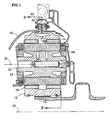
FIG. 1 is a cross sectional side elevation view of a gear train configured as a star system and useful in an aircraft gas turbine engine. -
FIG. 2 is a schematic view in thedirection 2--2 ofFIG. 1 . -
FIG. 3 is a schematic view similar toFIG. 2 illustrating a gear train configured as a planetary system. -
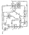
FIG. 4 is a schematic diagram showing a lubrication system in a normal state of operation, i.e. with the lubricant pressure at a normal level. -
FIG. 5 is a schematic diagram showing the lubrication system ofFIG. 4 shortly after the onset of an abnormal state of operation, i.e. with the lubricant pressure lower than a normal level. -
FIG. 6 is a schematic diagram similar toFIG. 5 showing the lubrication system at a later time. -
FIG. 7 is a schematic view showing an auxiliary lubricant tank with a bypass conduit and a discharge conduit for accommodating reduced-G operation. -
FIG. 8 is a schematic view showing an auxiliary lubricant tank with a continuous conduit extending through the tank without interruption for accommodating reduced-G operation. - Referring to
FIGS. 1 and2 , a reduction gear train suitable for use in an aircraft gas turbine engine includes asun gear 10 driven by a sun gear (input)shaft 12, aring gear 14 radially outboard of the sun gear and connected to a ring gear (output)shaft 16, and a set ofintermediate gears 18 radially intermediate and meshing with the sun and ring gears. Each intermediate gear circumscribes ajournal pin 20. A thin, replenishable film of lubricant, not shown, occupies a smallannular space 22 between each intermediate gear and its journal pin to support the intermediate gear. This arrangement is referred to as a journal bearing. The journal pins are all supported by acarrier 24. The carrier interconnects the journal pins with each other and, by doing so, also interconnects the intermediate gears to each other. Alubricant recovery gutter 26 circumscribes the ring gear. - In the gear train shown in
FIGS. 1 and2 , the sun and ring gears are each rotatable about anaxis 28. The carrier is non-rotatable even though the individual intermediate gears are each rotatable about theirrespective axes 30. Such a system is referred to as a star system. As seen best inFIG. 2 , the input and output shafts counterrotate. Lubricant flows through the gear system to support theintermediate gears 18 on thejournal pins 20 and to lubricate and cool the gear teeth. The used lubricant expelled by the gear train enters thegutter 26 by various paths, which includelubricant slots 32. - Alternatively, as seen in
FIG. 3 , the sun gear and carrier are rotatable about theaxis 28. The ring gear is non rotatable. The carrier is connected to an output shaft. Such a system is referred to as a planetary system. The input and output shafts co-rotate as indicated inFIG. 3 . Finally, all three components may be rotatable aboutaxis 28 so that dual output shafts connected to the carrier and the ring gear counterrotate with respect to each other. - Many of the engine components, including the
gears journal pins 20 are far less tolerant of lubricant starvation. Accordingly, whether the gear system is configured as a star, a planetary or with all three gears rotatable, it is desirable to ensure that lubricant flows to the journal pins, at least temporarily under all conditions. The temporary lubricant supply allows time for normal operation to resume or for the engine to be shut down before significant damage can occur. -
FIG. 4 schematically shows the relevant components of the above described gear train (gears journal pin 20 and gutter 26),other engine components 36 requiring lubrication, and a lubrication system suitable for use with the gear train. The lubrication system includes a main system whose components include asump 38, ascavenge pump 40 for scavenging lubricant from the sump, amain tank 42 for receiving lubricant from the scavenge pump, amain pump 44 for pumping lubricant from the main tank, and various lubricant reconditioning components such as chip detectors, heat exchangers and deaerators, collectively designated 46. The lubrication system also includes an auxiliary system whose components include an auxiliary lubricant tank orreservoir 48 and anauxiliary pump 50. The lubrication system also includes a pressureresponsive valve 54. - An auxiliary
tank supply conduit 58 extends from thegutter 26 to theauxiliary tank 48. The gutter serves as a source of lubricant for the tank. Amain bypass line 60 branches from the supply conduit at ajunction 62 and extends to thesump 38. An auxiliarytank discharge conduit 64 extends from the auxiliary tank to the auxiliary pump. An auxiliarypump discharge line 66 extends from the auxiliary pump to the pressure responsive valve. A maintank return line 68 extends from thevalve 54 to themain lubricant tank 42. Alubricant delivery pathway 70 extends from themain pump 44 through the variouslubricant reconditioning components 36 and ultimately to thegears other components 46. Alubricant return pathway 72 extends from the components to thesump 38. Aportion 76 of thedelivery pathway 70 leads to the pressureresponsive valve 54. A journalpin delivery line 78 extends from the valve to thejournal pins 20. - It should be appreciated that the above description and the schematic illustration and are highly simplified in comparison to an actual lubrication system. For example, an actual system may have multiple lubricant conduits, lines, pathways, pumps, etc. corresponding to each of the components discussed above and illustrated.
- The lubrication system is operable in both normal and abnormal states of operation. Those skilled in the art will appreciate that normal operation refers to the expected, trouble-free state of operation in which the lubrication system substantially meets its design specification. For example, the normal state is a state of operation in which the system delivers lubricant at the rates, temperatures, pressures, etc. determined by the designer so that the lubricated components, including the gears and journal pins; receive a quantity of lubricant enabling them to operate as intended. The skilled artisan will also appreciate that abnormal operation refers to a state of operation other than the normal state.
- During normal operation, rotation of the gears expels lubricant radially outwardly, and with a high tangential velocity, into the
lubricant recovery gutter 26. Thesupply conduit 58, which branches substantially tangentially off the gutter as seen inFIGS. 7 and8 , captures the expelled lubricant. Alarge portion 82 of the lubricant flows through themain bypass line 60 and returns to thesump 38. Asmaller portion 84 of the lubricant flows into theauxiliary tank 48 to establish or replenish a reserve quantity of lubricant therein. Theauxiliary pump 50 pumps lubricant from the tank to the pressureresponsive valve 54. Concurrently, thescavenge pump 40 extracts lubricant from thesump 38 and delivers it to themain tank 42. Themain pump 44 pumps the lubricant from the tank to thereconditioning components 46. Mbst of the reconditionedlubricant 86 then flows to thegears other components 36. Theremainder 88 of the lubricant flows to the pressure responsive valve. The valve, responding to normal pressure in the lubrication system, directs this remaininglubricant 88 to the journal pins and directs reserve lubricant 90 (received from the auxiliary pump) to themain tank 42. - Referring now to
FIG. 5 , immediately after the onset of abnormal operation (e.g. due to a severe leak, clog or malfunction of a system component) the lubricant pressure drops such that an unsatisfactorily reduced quantity of lubricant flows through thelubricant delivery pathway 70. In response to the abnormally low pressure, the pressureresponsive valve 54 shunts thereserve lubricant 90 received from the auxiliary pump to the journal pins 20 to ensure that the pins receive lubricant, at least temporarily. The gear system at first continues to expel a large quantity of lubricant into the gutter. As with normal operation, alarge portion 82 of the lubricant flows through themain bypass line 60 and returns to thesump 38. Asmaller portion 84 of the lubricant flows to the auxiliary tank to at least partially replenish the lubricant being withdrawn by the auxiliary pump. - If the abnormally low lubricant pressure persists, the system reaches the state shown in
FIG. 6 . The quantity of lubricant circulating through the system is small enough that little or no lubricant backs up from the auxiliary tank and enters themain bypass line 60. Instead, nearly all of the limited quantity of lubricant flows to theauxiliary pump 50 and eventually back to the journal pins 20. This state of operation persists until thetank 48 is depleted and the flow rate from thegutter 26 is insufficient to replenish it. - Although the above-described system is satisfactory during normal-G operation, it may be desirable to extend such satisfactory operability tp reduced-G conditions irrespective of whether the lubricant pressure is normal (
FIG. 4 ) or is abnormally low (FIGS. 5 and6 ). Reduced-G conditions include positive-G conditions materially less than 9.8 meters/sec./sec., particularly when such conditions result in an inability of the main lubricant system to satisfy the lubrication requirements of the gears, journal pins and other components requiring lubrication. Reduced-G conditions also includes non-positive-G conditions, i.e. zero-G and negative-G conditions. Reduced-G conditions can arise from aircraft maneuvers and/or aircraft orientation. -
FIG. 7 illustrates thering gear 14,gutter 26 andsupply conduit 58, which extends substantially tangentially from the gutter. Themain bypass line 60 branches from the supply conduit at thejunction 62 upstream of aconduit outlet 94. An optional valve such asflapper valve 96 regulates lubricant flow from the outlet. The valve may be loaded, for example by a spring, to its closed position. Theauxiliary tank 48 is mounted to a non-rotatable mechanical ground. The tank has a top 100, a bottom 102 and an arcuate profile with radially inner andouter boundaries G bypass line 108 branches from the conduit downstream of thejunction 62 and upstream of theconduit outlet 94. The bypass line has aninlet 110, and anoutlet 112 inside the auxiliary tank. Theoutlet 112 is at a first elevation, E1, preferably near the bottom of the tank. - The system also includes an auxiliary
tank discharge conduit 116. Thedischarge conduit 116 has an arcuate profile with radially inner andouter boundaries perforations 122. The perforations may all have the same area, however, as explained below, it may be desirable for the area of the individual perforations to decrease, or at least not increase, with decreasing elevation. The opening, whatever form it takes, is at least partially at a second elevation E2 higher than the first elevation E1 . For example, in the illustrated, perforated variant, at least some of the perforations are higher than E1 . - As used herein, "elevation" refers to distance or height above a reference height H no higher than the bottom of the
tank 48 when the system is in the orientation seen inFIG. 7 , i.e. an orientation representative of the engine or aircraft being on level ground or in straight and level flight. - During normal positive-G operation (G approximately equal to 9.8 m/sec./sec.) with normal lubricant pressure, lubricant enters the auxiliary tank, principally by way of the
outlet 94, although some lubricant may enter the tank by flowing through thebypass line 108 and itsoutlet 112. During normal positive-G operation with abnormally low lubricant pressure, thevalve 96, if present, may close so that lubricant still flowing through theconduit 58 enters the tank by way of thebypass line 108. Either way, the lubricant exits the tank through the auxiliarytank discharge conduit 116 after first passing through the opening represented byperforations 122. - During reduced-G operation, particularly zero-G or negative-G, the lubricant pressure may be low enough that a reduced quantity of lubricant (including no lubricant) flows through the
supply conduit 58. The low lubricant pressure may result from a malfunction in the lubrication system or it may occur because the reduced-G's have lifted lubricant away from theoutlet 124 of the main tank (FIG 4 ) in a system that is otherwise fully functional. Theflapper valve 96, if present, closes. Lubricant still circulating in the system is impelled throughsupply conduit 58 as a result of the tangential velocity imparted to the lubricant by the rotation of the gears. That lubricant enters the tank by way of thebypass line 108 and itsoutlet 112. For negative-G operation, the lubricant will migrate toward the top of the tank. However because the array ofperforations 122 is at least partially at an elevation E2 higher than outlet elevation E1, the lubricant can enter thedischarge conduit 116 by way of theperforations 122. Because the lubricant migrates toward the top of the tank during negative-G operation, there will be a tendency for theauxiliary pump 50 to extract air from the bottom of the tank rather than lubricant from the top of the tank. This tendency can be partially counteracted if theperforations 122 are of decreasing area with decreasing elevation. The lubricant is encouraged to enter the discharge conduit partly because of the negative-G's and partly due to suction created by theauxiliary pump 50. Because the conduit is arcuate, the lubricant will tend to accumulate along the radiallyouter boundary 120 of the conduit so that it can be extracted by thepump 50. For zero-G operation, the system operates similarly except that the lubricant will tend to float and will not be able to enter the conduit as readily. -
FIG. 8 illustrates thering gear 14,gutter 26 andsupply conduit 58, which extends substantially tangentially from the gutter. Themain bypass line 60 branches from the conduit at thejunction 62. Theauxiliary tank 48 is mounted to a non-rotatable mechanical ground. The tank has a top 100, a bottom 102 and an arcuate profile with radially inner andouter boundaries - The system also includes an auxiliary
tank discharge conduit 128. The discharge conduit may be a component physically distinct from thesupply conduit 58 and connected thereto by a fitting or other appropriate connection as shown. Alternatively, the discharge conduit may be an integral extension or continuation of thesupply conduit 58, with the interface between theconduits auxiliary tank 48. The conduit extends continuously and without interruption through the tank. - The
discharge conduit 128 has an arcuate profile with radially inner andouter boundaries perforations 136. The perforations may all have the same area. However, as explained above, it may be desirable for the area of the individual perforations to decrease, or at least not increase, with decreasing elevation in order to reduce the tendency for thepump 50 to extract air rather than lubricant during negative-G operation. - As used herein, "elevation" refers to distance or height above a reference height H no higher than the bottom of the
tank 48 when the system is in the orientation seen inFIG. 8 , i.e. an orientation representative of the engine or aircraft being on level ground or in straight and level flight. - During normal positive-G operation (G approximately equal to 9.8 m/sec./sec.) with normal lubricant pressure, lubricant delivered by
supply conduit 58 flows through the perforations to establish a reserve quantity of lubricant in theauxiliary tank 48. Excess lubricant flows through thedischarge conduit 128 to the auxiliary pump 50 (FIG. 4 ). During positive-G operation with abnormally low lubricant pressure, the quantity of lubricant circulating through the lubrication system is typically reduced relative to the normal quantity (in the limit, the reduced quantity may be zero) . The reduced quantity flows into the discharge conduit and adds to residual lubricant in the tank and/or flows through the discharge conduit to the auxiliary pump. - During reduced-G operation, particularly zero-G. or negative-G, the lubricant pressure may be low enough that a reduced quantity of lubricant (including no lubricant) flows through the
supply conduit 58. The low lubricant pressure may result from a malfunction in the lubrication system or it may occur because the reduced-G's have lifted lubricant away from theoutlet 124 of the main tank (FIG 4 ) in a system that is otherwise fully functional. Lubricant still circulating in the system is impelled throughsupply conduit 58 as a result of the tangential velocity imparted to the lubricant by the rotation of the gears. That lubricant flows from thesupply conduit 58 into thedischarge conduit 128. For negative-G operation, any lubricant already in the tank migrates toward the top of the tank. Theperforations 136 admit this lubricant to the discharge conduit to augment any lubricant arriving from thesupply conduit 58. The lubricant in the tank is encouraged to enter the discharge conduit partly because of the negative-G's and partly due to suction created by theauxiliary pump 50. Because the conduit is arcuate, the lubricant will tend to accumulate along the radiallyouter boundary 134 of the conduit so that it can be extracted by thepump 50. For zero-G operation, the system operates similarly except that the lubricant will tend to float and will not be able to enter the conduit as readily. - Although this disclosure refers to specific embodiments of the lubrication system, it will be understood by those skilled in the art that various changes in form and detail may be made without departing from the subject matter set forth in the accompanying claims.
Claims (10)
- A lubrication system, comprising:an auxiliary lubricant tank (48); anda conduit (128) extending without interruption through the auxiliary lubricant tank (48), a portion of the conduit (128) residing within the tank having an opening (136) for allowing lubricant transfer between the tank (48) and the conduit (128).
- The lubrication system of claim 1 wherein the source of lubricant is a lubricant recovery gutter (36) associated with a gear train.
- A lubrication system for use with a gear train, the gear train including a ring gear (14) and a gutter (36) radially outboard of the ring gear (14), the lubrication system comprising:an auxiliary lubricant tank (48); anda conduit (128) extending without interruption through the auxiliary lubricant tank (48), a portion of the conduit (128) residing within the tank (48) having an opening (136) for allowing lubricant transfer between the tank (48) and the conduit (128).
- The lubrication system of claim 7 wherein the gear train includes a sun gear (10) radially inboard of the ring gear (14) and a set of intermediate gears (18) radially intermediate the sun gear (10) and the ring gear (14), the intermediate gears (18) being interconnected by a carrier (24).
- The lubrication system of claim 4 wherein the sun (10) and ring (14) gears are rotatable about an axis and the carrier (24) is non-rotatable about the axis.
- The lubrication system of claim 4 wherein the sun gear (10) and carrier (24) are rotatable about an axis and the ring gear (14) is non-rotatable about the axis.
- The lubrication system of any preceding claim wherein the opening is an array of perforations (136).
- The lubrication system of claim 7 wherein the perforations (136) each have an area that decreases with decreasing elevation.
- The lubrication system of any preceding claim wherein the resident portion of the tank discharge conduit (128) has an arcuate profile with radially inner and outer boundaries (132, 134), the opening (136) of the resident portion being along the radially inner boundary (132).
- The lubrication system of any preceding claim wherein the opening (136) facilitates lubricant admission into the conduit (128) during reduced-G operation.
Applications Claiming Priority (1)
| Application Number | Priority Date | Filing Date | Title |
|---|---|---|---|
| US11/603,393 US8020665B2 (en) | 2006-11-22 | 2006-11-22 | Lubrication system with extended emergency operability |
Publications (3)
| Publication Number | Publication Date |
|---|---|
| EP1925855A2 true EP1925855A2 (en) | 2008-05-28 |
| EP1925855A3 EP1925855A3 (en) | 2010-08-11 |
| EP1925855B1 EP1925855B1 (en) | 2015-09-02 |
Family
ID=38984246
Family Applications (1)
| Application Number | Title | Priority Date | Filing Date |
|---|---|---|---|
| EP07254542.9A Active EP1925855B1 (en) | 2006-11-22 | 2007-11-22 | Lubrication system with extended emergency operability |
Country Status (2)
| Country | Link |
|---|---|
| US (2) | US8020665B2 (en) |
| EP (1) | EP1925855B1 (en) |
Cited By (16)
| Publication number | Priority date | Publication date | Assignee | Title |
|---|---|---|---|---|
| EP2270361A3 (en) * | 2009-06-26 | 2011-03-30 | United Technologies Corporation | Epicyclic gear system with load share reduction |
| EP2322766A3 (en) * | 2009-11-12 | 2012-08-08 | United Technologies Corporation | Oil capture and bypass system |
| DE102011075906A1 (en) * | 2011-05-16 | 2012-11-22 | Zf Friedrichshafen Ag | Planetary bolt for holding planetary wheel utilized for load distribution in planetary gear for wind power plant, has supporting portions coupled with planetary wheel and separated from each other by bending portion |
| EP2554874A3 (en) * | 2011-08-02 | 2013-05-22 | United Technologies Corporation | Journal pin oil supply for gear system |
| FR2987402A1 (en) * | 2012-02-23 | 2013-08-30 | Snecma | Fan module for double-flow turbojet, has reducer carried by support casing that is able to be fixed on support of turbojet such that reducer is able to be mounted on fan module beforehand or during simultaneous assembly of fan module |
| EP2672148A1 (en) * | 2012-06-08 | 2013-12-11 | Rolls-Royce plc | Oil scavenge arrangement |
| US8939864B2 (en) | 2006-08-15 | 2015-01-27 | United Technologies Corporation | Gas turbine engine lubrication |
| US9115650B2 (en) | 2006-08-15 | 2015-08-25 | United Technologies Corporation | Ring gear mounting arrangement with oil scavenge scheme |
| EP2898202A4 (en) * | 2012-09-19 | 2016-03-09 | United Technologies Corp | Lubrication system having porous feature |
| EP2855882A4 (en) * | 2012-05-31 | 2016-04-13 | United Technologies Corp | Lubrication arrangement for a gas turbine engine gear assembly |
| EP2538055A3 (en) * | 2011-06-22 | 2016-12-21 | United Technologies Corporation | Oil bypass channel deaerator for a geared turbofan engine |
| EP3171168A1 (en) * | 2015-11-17 | 2017-05-24 | United Technologies Corporation | Monitoring system for non-ferrous metal particles |
| US9976437B2 (en) | 2006-08-15 | 2018-05-22 | United Technologies Corporation | Epicyclic gear train |
| US10082105B2 (en) | 2006-08-15 | 2018-09-25 | United Technologies Corporation | Gas turbine engine with geared architecture |
| US10196989B2 (en) | 2006-08-15 | 2019-02-05 | United Technologies Corporation | Gas turbine engine gear train |
| EP3628894A1 (en) * | 2011-12-30 | 2020-04-01 | United Technologies Corporation | Gear apparatus and turbine engine |
Families Citing this family (155)
| Publication number | Priority date | Publication date | Assignee | Title |
|---|---|---|---|---|
| US7926260B2 (en) * | 2006-07-05 | 2011-04-19 | United Technologies Corporation | Flexible shaft for gas turbine engine |
| US7704178B2 (en) | 2006-07-05 | 2010-04-27 | United Technologies Corporation | Oil baffle for gas turbine fan drive gear system |
| US8667688B2 (en) | 2006-07-05 | 2014-03-11 | United Technologies Corporation | Method of assembly for gas turbine fan drive gear system |
| US8708863B2 (en) | 2006-08-15 | 2014-04-29 | United Technologies Corporation | Epicyclic gear train |
| US20120213628A1 (en) | 2006-08-15 | 2012-08-23 | Mccune Michael E | Gas turbine engine with geared architecture |
| EP2074306A1 (en) | 2006-10-12 | 2009-07-01 | United Technologies Corporation | Dual function cascade integrated variable area fan nozzle and thrust reverser |
| US8020665B2 (en) * | 2006-11-22 | 2011-09-20 | United Technologies Corporation | Lubrication system with extended emergency operability |
| US20080273961A1 (en) | 2007-03-05 | 2008-11-06 | Rosenkrans William E | Flutter sensing and control system for a gas turbine engine |
| US11346289B2 (en) | 2007-08-01 | 2022-05-31 | Raytheon Technologies Corporation | Turbine section of high bypass turbofan |
| US11149650B2 (en) | 2007-08-01 | 2021-10-19 | Raytheon Technologies Corporation | Turbine section of high bypass turbofan |
| US20150377123A1 (en) | 2007-08-01 | 2015-12-31 | United Technologies Corporation | Turbine section of high bypass turbofan |
| US11486311B2 (en) | 2007-08-01 | 2022-11-01 | Raytheon Technologies Corporation | Turbine section of high bypass turbofan |
| US11242805B2 (en) | 2007-08-01 | 2022-02-08 | Raytheon Technologies Corporation | Turbine section of high bypass turbofan |
| US9701415B2 (en) | 2007-08-23 | 2017-07-11 | United Technologies Corporation | Gas turbine engine with axial movable fan variable area nozzle |
| US9957918B2 (en) | 2007-08-28 | 2018-05-01 | United Technologies Corporation | Gas turbine engine front architecture |
| US20140157754A1 (en) | 2007-09-21 | 2014-06-12 | United Technologies Corporation | Gas turbine engine compressor arrangement |
| US8356693B2 (en) * | 2007-09-24 | 2013-01-22 | Honeywell International Inc. | Overboard vent valve for use in an aircraft bearing lubrication system |
| FI122381B (en) * | 2008-01-03 | 2011-12-30 | Moventas Oy | planetary Gearbox |
| EP2297461B1 (en) * | 2008-06-02 | 2012-10-03 | Vestas Wind Systems A/S | A lubrication system for a gear system for a wind turbine |
| US20140174056A1 (en) | 2008-06-02 | 2014-06-26 | United Technologies Corporation | Gas turbine engine with low stage count low pressure turbine |
| US8230835B2 (en) * | 2009-03-10 | 2012-07-31 | Honeywell International Inc. | Emergency engine lubrication systems and methods |
| US9885313B2 (en) | 2009-03-17 | 2018-02-06 | United Technologes Corporation | Gas turbine engine bifurcation located fan variable area nozzle |
| US8511055B2 (en) * | 2009-05-22 | 2013-08-20 | United Technologies Corporation | Apparatus and method for providing damper liquid in a gas turbine |
| FR2953898B1 (en) | 2009-12-11 | 2012-03-30 | Eurocopter France | METHOD FOR INCREASING THE SAFETY OF A MOTOR INSTALLATION, AND MOTOR INSTALLATION SUITABLE FOR CARRYING OUT SAID METHOD |
| US9995174B2 (en) | 2010-10-12 | 2018-06-12 | United Technologies Corporation | Planetary gear system arrangement with auxiliary oil system |
| US9458923B2 (en) * | 2011-03-31 | 2016-10-04 | Textron Innovations Inc. | Gearbox with passive lubrication system |
| US10605167B2 (en) | 2011-04-15 | 2020-03-31 | United Technologies Corporation | Gas turbine engine front center body architecture |
| US9410608B2 (en) | 2011-06-08 | 2016-08-09 | United Technologies Corporation | Flexible support structure for a geared architecture gas turbine engine |
| US9239012B2 (en) | 2011-06-08 | 2016-01-19 | United Technologies Corporation | Flexible support structure for a geared architecture gas turbine engine |
| US9631558B2 (en) | 2012-01-03 | 2017-04-25 | United Technologies Corporation | Geared architecture for high speed and small volume fan drive turbine |
| US9909505B2 (en) | 2011-07-05 | 2018-03-06 | United Technologies Corporation | Efficient, low pressure ratio propulsor for gas turbine engines |
| US9506422B2 (en) | 2011-07-05 | 2016-11-29 | United Technologies Corporation | Efficient, low pressure ratio propulsor for gas turbine engines |
| US9938898B2 (en) | 2011-07-29 | 2018-04-10 | United Technologies Corporation | Geared turbofan bearing arrangement |
| US8550955B2 (en) * | 2011-08-16 | 2013-10-08 | General Electric Company | Pin for planetary gear system |
| US8651240B1 (en) | 2012-12-24 | 2014-02-18 | United Technologies Corporation | Pressurized reserve lubrication system for a gas turbine engine |
| US9416677B2 (en) | 2012-01-10 | 2016-08-16 | United Technologies Corporation | Gas turbine engine forward bearing compartment architecture |
| US9920880B2 (en) * | 2012-01-16 | 2018-03-20 | Hamilton Sundstrand Corporation | Deaerating assembly |
| US8771124B2 (en) | 2012-01-16 | 2014-07-08 | Hamilton Sundstrand Corporation | Carrier for planetary gear system |
| US20130186058A1 (en) | 2012-01-24 | 2013-07-25 | William G. Sheridan | Geared turbomachine fan and compressor rotation |
| US10415468B2 (en) | 2012-01-31 | 2019-09-17 | United Technologies Corporation | Gas turbine engine buffer system |
| US10113434B2 (en) | 2012-01-31 | 2018-10-30 | United Technologies Corporation | Turbine blade damper seal |
| US20130192191A1 (en) | 2012-01-31 | 2013-08-01 | Frederick M. Schwarz | Gas turbine engine with high speed low pressure turbine section and bearing support features |
| US10724431B2 (en) | 2012-01-31 | 2020-07-28 | Raytheon Technologies Corporation | Buffer system that communicates buffer supply air to one or more portions of a gas turbine engine |
| US8863491B2 (en) | 2012-01-31 | 2014-10-21 | United Technologies Corporation | Gas turbine engine shaft bearing configuration |
| US10287914B2 (en) | 2012-01-31 | 2019-05-14 | United Technologies Corporation | Gas turbine engine with high speed low pressure turbine section and bearing support features |
| US20130192198A1 (en) | 2012-01-31 | 2013-08-01 | Lisa I. Brilliant | Compressor flowpath |
| US8869508B2 (en) | 2012-01-31 | 2014-10-28 | United Technologies Corporation | Gas turbine engine variable area fan nozzle control |
| US10400629B2 (en) | 2012-01-31 | 2019-09-03 | United Technologies Corporation | Gas turbine engine shaft bearing configuration |
| US20130192251A1 (en) | 2012-01-31 | 2013-08-01 | Peter M. Munsell | Buffer system that communicates buffer supply air to one or more portions of a gas turbine engine |
| US20150345426A1 (en) | 2012-01-31 | 2015-12-03 | United Technologies Corporation | Geared turbofan gas turbine engine architecture |
| US8720306B2 (en) | 2012-01-31 | 2014-05-13 | United Technologies Corporation | Turbine engine gearbox |
| US9835052B2 (en) | 2012-01-31 | 2017-12-05 | United Technologies Corporation | Gas turbine engine with high speed low pressure turbine section and bearing support features |
| US20130192240A1 (en) | 2012-01-31 | 2013-08-01 | Peter M. Munsell | Buffer system for a gas turbine engine |
| US9394852B2 (en) | 2012-01-31 | 2016-07-19 | United Technologies Corporation | Variable area fan nozzle with wall thickness distribution |
| US9169781B2 (en) | 2012-01-31 | 2015-10-27 | United Technologies Corporation | Turbine engine gearbox |
| US10107191B2 (en) | 2012-02-29 | 2018-10-23 | United Technologies Corporation | Geared gas turbine engine with reduced fan noise |
| US8790075B2 (en) | 2012-03-30 | 2014-07-29 | United Technologies Corporation | Gas turbine engine geared architecture axial retention arrangement |
| US10125693B2 (en) | 2012-04-02 | 2018-11-13 | United Technologies Corporation | Geared turbofan engine with power density range |
| US10138809B2 (en) | 2012-04-02 | 2018-11-27 | United Technologies Corporation | Geared turbofan engine with a high ratio of thrust to turbine volume |
| US20150308351A1 (en) * | 2012-05-31 | 2015-10-29 | United Technologies Corporation | Fundamental gear system architecture |
| US9410448B2 (en) * | 2012-05-31 | 2016-08-09 | United Technologies Corporation | Auxiliary oil system for negative gravity event |
| US20130319006A1 (en) * | 2012-05-31 | 2013-12-05 | Francis Parnin | Direct feed auxiliary oil system for geared turbofan engine |
| US8572943B1 (en) | 2012-05-31 | 2013-11-05 | United Technologies Corporation | Fundamental gear system architecture |
| US9341115B2 (en) | 2012-06-26 | 2016-05-17 | United Technologies Corporation | Valve for controlling flow of a turbomachine fluid |
| US8978829B2 (en) | 2012-07-02 | 2015-03-17 | United Technologies Corporation | Turbomachine fluid delivery system |
| US9404381B2 (en) | 2012-09-04 | 2016-08-02 | United Technologies Corporation | Turbine engine transmission gutter |
| US8985278B2 (en) * | 2012-09-07 | 2015-03-24 | United Technologies Corporation | Lubrication system having segmented anti-backflow feature |
| US10247095B2 (en) | 2012-09-28 | 2019-04-02 | United Technologies Corporation | Reduced trim flow gas turbine engine oil system |
| US9366156B2 (en) | 2012-09-28 | 2016-06-14 | United Technologies Corporation | Axial sealing gravity based siphon system |
| US9863319B2 (en) | 2012-09-28 | 2018-01-09 | United Technologies Corporation | Split-zone flow metering T-tube |
| EP2904234B1 (en) | 2012-10-08 | 2020-04-22 | United Technologies Corporation | Geared turbine engine with relatively lightweight propulsor module |
| US11280271B2 (en) | 2012-10-09 | 2022-03-22 | Raytheon Technologies Corporation | Operability geared turbofan engine including compressor section variable guide vanes |
| US8900090B2 (en) | 2012-11-30 | 2014-12-02 | United Technologies Corporation | Geared architecture gas turbine engine with improved lubrication and misalignment tolerant roller bearing system |
| CN103016698B (en) * | 2012-12-10 | 2016-03-02 | 中国船舶重工集团公司第七〇五研究所 | A kind of high-speed overload power transmission lubrication feeding mechanism being applicable to submarine navigation device |
| US9920653B2 (en) | 2012-12-20 | 2018-03-20 | United Technologies Corporation | Low pressure ratio fan engine having a dimensional relationship between inlet and fan size |
| US9932933B2 (en) | 2012-12-20 | 2018-04-03 | United Technologies Corporation | Low pressure ratio fan engine having a dimensional relationship between inlet and fan size |
| US10247020B2 (en) | 2013-01-15 | 2019-04-02 | United Technologies Corporation | Fluid collection gutter for a geared turbine engine |
| EP3961068A1 (en) * | 2013-01-15 | 2022-03-02 | Raytheon Technologies Corporation | Fluid collection gutter for a geared turbine engine |
| US11073044B2 (en) * | 2013-01-21 | 2021-07-27 | Raytheon Technologies Corporation | Adjustable floating oil channel for gas turbine engine gear drive |
| US10436120B2 (en) | 2013-02-06 | 2019-10-08 | United Technologies Corporation | Exhaust nozzle for an elongated gear turbofan with high bypass ratio |
| US11053815B2 (en) | 2013-02-06 | 2021-07-06 | Raytheon Technologies Corporation | Multi-circuit lubrication system for a turbine engine |
| US10605104B2 (en) | 2013-02-06 | 2020-03-31 | United Technologies Corporation | Multi-circuit lubrication system for a turbine engine |
| EP2959129B1 (en) | 2013-02-25 | 2019-12-18 | United Technologies Corporation | Auxiliary lubricant supply pump stage integral with main lubricant pump stage |
| US8870699B2 (en) | 2013-03-11 | 2014-10-28 | Pratt & Whitney Canada Corp. | Lubrication oil system for a reduction gearbox |
| US9863326B2 (en) | 2013-03-12 | 2018-01-09 | United Technologies Corporation | Flexible coupling for geared turbine engine |
| US10605172B2 (en) | 2013-03-14 | 2020-03-31 | United Technologies Corporation | Low noise turbine for geared gas turbine engine |
| US11719161B2 (en) | 2013-03-14 | 2023-08-08 | Raytheon Technologies Corporation | Low noise turbine for geared gas turbine engine |
| US9885282B2 (en) | 2013-03-15 | 2018-02-06 | United Technologies Corporation | Turbofan engine bearing and gearbox arrangement |
| US10724479B2 (en) | 2013-03-15 | 2020-07-28 | United Technologies Corporation | Thrust efficient turbofan engine |
| JP6031594B2 (en) * | 2013-04-12 | 2016-11-24 | 本田技研工業株式会社 | Vehicle oil suction device |
| US10287917B2 (en) | 2013-05-09 | 2019-05-14 | United Technologies Corporation | Turbofan engine front section |
| US10920616B2 (en) | 2013-08-21 | 2021-02-16 | Raytheon Technologies Corporation | Integral gutter and front center body |
| US9726083B2 (en) * | 2013-08-21 | 2017-08-08 | United Technologies Corporation | Load balanced journal bearing pin for planetary gear |
| US10533522B2 (en) | 2013-08-21 | 2020-01-14 | United Technologies Corporation | Load balanced journal bearing pin |
| WO2015076902A2 (en) * | 2013-09-09 | 2015-05-28 | United Technologies Corporation | Reservoir egress fluid coupler |
| EP3044438B1 (en) | 2013-09-13 | 2018-07-04 | United Technologies Corporation | Fan drive gear system auxiliary pump monitoring system |
| US9835086B2 (en) * | 2013-10-08 | 2017-12-05 | United Technologies Corporation | Low loss oil accumulator assembly |
| US10371047B2 (en) | 2013-10-16 | 2019-08-06 | United Technologies Corporation | Geared turbofan engine with targeted modular efficiency |
| US10502163B2 (en) | 2013-11-01 | 2019-12-10 | United Technologies Corporation | Geared turbofan arrangement with core split power ratio |
| WO2015112212A2 (en) | 2013-11-01 | 2015-07-30 | United Technologies Corporation | Geared turbofan arrangement with core split power ratio |
| US9316630B2 (en) * | 2013-11-08 | 2016-04-19 | Sikorsky Aircraft Corporation | Anti-clog and non-metallic debris detector for lubrication system inlet |
| US8869504B1 (en) | 2013-11-22 | 2014-10-28 | United Technologies Corporation | Geared turbofan engine gearbox arrangement |
| US10072521B2 (en) | 2013-12-05 | 2018-09-11 | United Technologies Corporation | FDGS auxiliary pump monitoring system |
| EP3102807B1 (en) * | 2014-01-20 | 2022-04-20 | Raytheon Technologies Corporation | Auxiliary oil system for geared gas turbine engine |
| US10570916B2 (en) | 2014-02-19 | 2020-02-25 | United Technologies Corporation | Gas turbine engine airfoil |
| WO2015175052A2 (en) | 2014-02-19 | 2015-11-19 | United Technologies Corporation | Gas turbine engine airfoil |
| US10570915B2 (en) | 2014-02-19 | 2020-02-25 | United Technologies Corporation | Gas turbine engine airfoil |
| WO2015175045A2 (en) | 2014-02-19 | 2015-11-19 | United Technologies Corporation | Gas turbine engine airfoil |
| US10465702B2 (en) | 2014-02-19 | 2019-11-05 | United Technologies Corporation | Gas turbine engine airfoil |
| EP3108121B1 (en) | 2014-02-19 | 2023-09-06 | Raytheon Technologies Corporation | Turbofan engine with geared architecture and lpc airfoils |
| EP3108107B1 (en) | 2014-02-19 | 2023-10-11 | Raytheon Technologies Corporation | Turbofan engine with geared architecture and lpc airfoils |
| US10502229B2 (en) | 2014-02-19 | 2019-12-10 | United Technologies Corporation | Gas turbine engine airfoil |
| EP3108106B1 (en) | 2014-02-19 | 2022-05-04 | Raytheon Technologies Corporation | Gas turbine engine airfoil |
| US10280843B2 (en) | 2014-03-07 | 2019-05-07 | United Technologies Corporation | Geared turbofan with integral front support and carrier |
| US10196926B2 (en) | 2014-04-11 | 2019-02-05 | United Technologies Corporation | Lubricating a rotating component during forward and/or reverse rotation |
| FR3020658B1 (en) * | 2014-04-30 | 2020-05-15 | Safran Aircraft Engines | LUBRICATION OIL RECOVERY HOOD FOR TURBOMACHINE EQUIPMENT |
| US10107157B2 (en) | 2014-05-28 | 2018-10-23 | United Technologies Corporation | Gas turbine engine lubrication system |
| DE102014107659A1 (en) * | 2014-05-30 | 2015-12-03 | Getrag Getriebe- Und Zahnradfabrik Hermann Hagenmeyer Gmbh & Cie Kg | Transmission for a motor vehicle |
| US9976490B2 (en) | 2014-07-01 | 2018-05-22 | United Technologies Corporation | Geared gas turbine engine with oil deaerator |
| US10060289B2 (en) | 2014-07-29 | 2018-08-28 | United Technologies Corporation | Geared gas turbine engine with oil deaerator and air removal |
| US10480636B2 (en) * | 2014-10-17 | 2019-11-19 | Sikorsky Aircraft Corporation | Anti-clog lubricant distribution assembly |
| US9982771B2 (en) | 2014-12-01 | 2018-05-29 | United Technologies Corporation | Lightweight and compliant journal pin |
| US9915225B2 (en) | 2015-02-06 | 2018-03-13 | United Technologies Corporation | Propulsion system arrangement for turbofan gas turbine engine |
| US10677343B2 (en) * | 2015-02-18 | 2020-06-09 | Sikorsky Aircraft Corporation | Fluid distribution assembly having anti-clog inlet housing |
| US9470093B2 (en) | 2015-03-18 | 2016-10-18 | United Technologies Corporation | Turbofan arrangement with blade channel variations |
| US10371168B2 (en) | 2015-04-07 | 2019-08-06 | United Technologies Corporation | Modal noise reduction for gas turbine engine |
| US9874145B2 (en) | 2015-04-27 | 2018-01-23 | United Technologies Corporation | Lubrication system for gas turbine engines |
| US10458270B2 (en) | 2015-06-23 | 2019-10-29 | United Technologies Corporation | Roller bearings for high ratio geared turbofan engine |
| US11066945B2 (en) | 2015-07-15 | 2021-07-20 | Raytheon Technologies Corporation | Fluid collection gutter for a geared turbine engine |
| US10267233B2 (en) | 2015-10-23 | 2019-04-23 | United Technologies Corporation | Method and apparatus for monitoring lubrication pump operation during windmilling |
| US10107135B2 (en) | 2015-10-26 | 2018-10-23 | United Technologies Corporation | Gas turbine engine with gearbox health features |
| US10508562B2 (en) | 2015-12-01 | 2019-12-17 | United Technologies Corporation | Geared turbofan with four star/planetary gear reduction |
| BE1024639B1 (en) * | 2016-10-13 | 2018-05-16 | Safran Aero Boosters S.A. | TURBOMACHINE OIL TANK |
| US10508571B2 (en) * | 2016-11-17 | 2019-12-17 | K.J. Manufacturing Co. | Complete volume draining oil pan and device |
| FR3059361B1 (en) * | 2016-11-28 | 2018-12-07 | Safran Aircraft Engines | OIL TANK COMPRISING A DEVICE FOR CONTROLLING THE OIL LEVEL |
| US9988955B1 (en) * | 2016-11-28 | 2018-06-05 | GM Global Technology Operations LLC | Dry sump system warm up strategy |
| US10669948B2 (en) | 2017-01-03 | 2020-06-02 | Raytheon Technologies Corporation | Geared turbofan with non-epicyclic gear reduction system |
| US10494998B2 (en) * | 2017-01-30 | 2019-12-03 | United Technologies Corporation | Lubrication of epicyclic gear system for gas turbine engine |
| US10794203B2 (en) * | 2017-03-22 | 2020-10-06 | General Electric Company | Scavenge tube for a gas turbine engine |
| US10711642B2 (en) * | 2017-03-31 | 2020-07-14 | Raytheon Technologies Corporation | Gas turbine engine lubrication system and apparatus with boost pump system |
| US10738646B2 (en) | 2017-06-12 | 2020-08-11 | Raytheon Technologies Corporation | Geared turbine engine with gear driving low pressure compressor and fan at common speed, and failsafe overspeed protection and shear section |
| US10724445B2 (en) | 2018-01-03 | 2020-07-28 | Raytheon Technologies Corporation | Method of assembly for fan drive gear system with rotating carrier |
| GB201816504D0 (en) | 2018-10-10 | 2018-11-28 | Rolls Royce Plc | Lubrication system |
| US11092020B2 (en) | 2018-10-18 | 2021-08-17 | Raytheon Technologies Corporation | Rotor assembly for gas turbine engines |
| US11236637B2 (en) * | 2018-12-21 | 2022-02-01 | Raytheon Technologies Corporation | Auxiliary lubrication system with flow management valve |
| US10851671B2 (en) | 2019-03-29 | 2020-12-01 | Pratt & Whitney Canada Corp. | Bending stiffening feature used for compliant journal bearing |
| US11441443B2 (en) | 2019-06-06 | 2022-09-13 | Raytheon Technologies Corporation | Systems and methods for monitoring and controlling a gas turbine engine |
| IT201900015515A1 (en) | 2019-09-03 | 2021-03-03 | Ge Avio Srl | GEAR UNIT WITH MANIFOLD FOR AERONAUTIC ENGINE |
| US11542845B2 (en) | 2019-11-05 | 2023-01-03 | Pratt & Whitney Canada Corp. | Aircraft engine lubrication system and method |
| US11162575B2 (en) | 2019-11-20 | 2021-11-02 | Raytheon Technologies Corporation | Geared architecture for gas turbine engine |
| US11781506B2 (en) | 2020-06-03 | 2023-10-10 | Rtx Corporation | Splitter and guide vane arrangement for gas turbine engines |
| US11814968B2 (en) | 2021-07-19 | 2023-11-14 | Rtx Corporation | Gas turbine engine with idle thrust ratio |
| US11754000B2 (en) | 2021-07-19 | 2023-09-12 | Rtx Corporation | High and low spool configuration for a gas turbine engine |
| US11719245B2 (en) | 2021-07-19 | 2023-08-08 | Raytheon Technologies Corporation | Compressor arrangement for a gas turbine engine |
| US20230349326A1 (en) * | 2022-04-29 | 2023-11-02 | General Electric Company | Passive auxiliary lubrication system |
Family Cites Families (52)
| Publication number | Priority date | Publication date | Assignee | Title |
|---|---|---|---|---|
| US1631537A (en) | 1922-04-17 | 1927-06-07 | Advance Rumely Co | Lubrication system for train of gears |
| US2373350A (en) | 1942-09-17 | 1945-04-10 | Sharples Corp | Purification of aviation oil |
| US2370484A (en) | 1942-12-01 | 1945-02-27 | Snow Nabstedt Gear Corp | Transmission mechanism |
| US2684591A (en) | 1945-06-22 | 1954-07-27 | Curtiss Wright Corp | Torquemeter |
| US2575986A (en) | 1949-03-21 | 1951-11-20 | Le Roy D Yoder | Bale handling hook |
| US2782658A (en) | 1951-01-18 | 1957-02-26 | Gen Motors Corp | Composite fluid and gear drive |
| US3023640A (en) | 1956-03-09 | 1962-03-06 | Rockwell Standard Co | Drive mechanism |
| US3049138A (en) | 1961-04-27 | 1962-08-14 | United Aircraft Prod | Liquid storage tank |
| US3533307A (en) | 1968-10-17 | 1970-10-13 | White Farm Equip | Multi-ratio vehicle transmission |
| US3776067A (en) | 1972-09-19 | 1973-12-04 | Curtiss Wright Corp | Planetary gear transmission |
| DE2344949C2 (en) | 1973-09-06 | 1984-02-16 | Klöckner-Humboldt-Deutz AG, 5000 Köln | Lubricating device for internal combustion engines for a safe oil supply on large slopes |
| JPS51140013A (en) | 1975-05-28 | 1976-12-02 | Hitachi Ltd | Turbocharger |
| JPS53130601U (en) * | 1977-03-24 | 1978-10-17 | ||
| JPS601320B2 (en) | 1977-04-19 | 1985-01-14 | 武田薬品工業株式会社 | Antibiotic BA-843 |
| US4153141A (en) | 1977-06-20 | 1979-05-08 | General Electric Company | Auxiliary oil supply system |
| US4249783A (en) * | 1979-02-13 | 1981-02-10 | Pullman Incorporated | Wheel hub structure with bearing lubrication |
| US4284174A (en) | 1979-04-18 | 1981-08-18 | Avco Corporation | Emergency oil/mist system |
| FR2465079A1 (en) | 1979-09-17 | 1981-03-20 | Snecma | AEROSOL RELIEF LUBRICATION DEVICE, IN PARTICULAR FOR FLYING VEHICLES |
| GB2059517B (en) | 1979-09-29 | 1983-06-22 | Rolls Royce | Lubrication system |
| US4329952A (en) | 1980-01-21 | 1982-05-18 | Buraas Vincent S | Oil control system for piston-type airplane engines |
| US4378711A (en) | 1980-09-29 | 1983-04-05 | Caterpillar Tractor Co. | Planetary mechanism having a fluid baffle |
| US4589826A (en) * | 1983-04-14 | 1986-05-20 | Bernard Zimmern | Method of lubricating bearings of a machine handling liquefiable gas |
| JPS6097312A (en) | 1983-10-31 | 1985-05-31 | Matsushita Electric Works Ltd | Illuminating device by falling light |
| US4650367A (en) * | 1983-11-30 | 1987-03-17 | Dietzler Daniel P | Internally reinforced extruded plastic pipe |
| JPS6097312U (en) * | 1983-12-10 | 1985-07-03 | 三菱重工業株式会社 | Head tank for lubricating oil |
| JPS6167815A (en) | 1984-09-12 | 1986-04-08 | Kino Seimitsu Kogyo Kk | Macrolens |
| JPS6167815U (en) * | 1984-10-11 | 1986-05-09 | ||
| US4704862A (en) * | 1985-05-29 | 1987-11-10 | United Technologies Corporation | Ducted prop engine |
| US4691119A (en) | 1985-06-20 | 1987-09-01 | Westinghouse Electric Corp. | Permanent magnet alternator power generation system |
| US4717000A (en) | 1986-08-05 | 1988-01-05 | Avco Corporation | Integrated emergency lubrication system |
| FR2624239A1 (en) | 1987-12-03 | 1989-06-09 | Cousin Cie Ets A & M Freres | REDUCING MECHANISM WITHOUT GAME USABLE IN PARTICULAR FOR THE ADJUSTMENT OF VARIOUS PARTS OF A MOTOR VEHICLE SEAT |
| US4858427A (en) | 1988-08-08 | 1989-08-22 | General Motors Corporation | Secondary oil system for gas turbine engine |
| US4888947A (en) | 1988-10-31 | 1989-12-26 | General Motors Corporation | Secondary oil system |
| IT1232583B (en) * | 1989-02-14 | 1992-02-26 | Fiat Aviazione | MECHANICAL BODY LUBRICATION PLANT, PARTICULARLY OF AERONAUTICAL USE, EQUIPPED WITH AN EMERGENCY DEVICE SUITABLE TO GUARANTEE A MINIMUM SUPPLY OF LUBRICANT OIL |
| US5167207A (en) | 1989-08-01 | 1992-12-01 | Shanshin Kogyo Kabushiki Kaisha | Two cycle engine for small boat |
| US5245820A (en) | 1989-12-13 | 1993-09-21 | Alliedsignal Inc. | Air turbine starter with passive hydraulic capacitor |
| FR2658577A1 (en) | 1990-02-20 | 1991-08-23 | Aerospatiale | EMERGENCY LUBRICATION DEVICE FOR REDUCER, PARTICULARLY FOR A MAIN TRANSMISSION OF A GIRAVION. |
| US5018601A (en) | 1990-06-27 | 1991-05-28 | Avco Corporation | Integrated emergency lubrication system having single feed line to bearings |
| US5046306A (en) | 1990-07-23 | 1991-09-10 | General Motors Corporation | Secondary oil system |
| JP3104987B2 (en) * | 1990-11-05 | 2000-10-30 | アイシン・エィ・ダブリュ株式会社 | Automatic transmission with backflow prevention return oil passage |
| US5102379A (en) | 1991-03-25 | 1992-04-07 | United Technologies Corporation | Journal bearing arrangement |
| US5251725A (en) | 1992-07-07 | 1993-10-12 | Castrol Limited | Lubrication of power drive comprising large diameter gear |
| US5472383A (en) * | 1993-12-27 | 1995-12-05 | United Technologies Corporation | Lubrication system for a planetary gear train |
| DE4444276A1 (en) | 1994-12-13 | 1996-06-20 | Jenbacher Energiesysteme Ag | Arrangement for conveying and cooling the lubricating oil of internal combustion engines |
| US6039667A (en) | 1998-09-24 | 2000-03-21 | The Falk Corporation | Sun gear lubrication and inspection mechanism |
| US6223616B1 (en) | 1999-12-22 | 2001-05-01 | United Technologies Corporation | Star gear system with lubrication circuit and lubrication method therefor |
| US6505644B2 (en) | 2000-06-09 | 2003-01-14 | Delphi Technologies, Inc. | Dual barrel jet fuel pump assembly for a fuel tank |
| JP2002089225A (en) * | 2000-09-20 | 2002-03-27 | Sanshin Ind Co Ltd | Lubricating device of engine for small vessel |
| US6463819B1 (en) | 2000-10-24 | 2002-10-15 | Pratt & Whitney Canada Corp. | Uninterruptible oil supply system |
| GB2388634A (en) * | 2002-05-15 | 2003-11-19 | Dana Automotive Ltd | Engine lubrication system having dual/auxiliary pump operation |
| TWI242622B (en) * | 2004-06-11 | 2005-11-01 | Shin-Tsang Li | Lubrication device for four-stroke engine |
| US8020665B2 (en) * | 2006-11-22 | 2011-09-20 | United Technologies Corporation | Lubrication system with extended emergency operability |
-
2006
- 2006-11-22 US US11/603,393 patent/US8020665B2/en active Active
-
2007
- 2007-11-22 EP EP07254542.9A patent/EP1925855B1/en active Active
-
2011
- 2011-08-18 US US13/213,048 patent/US8511435B2/en active Active
Non-Patent Citations (1)
| Title |
|---|
| None |
Cited By (38)
| Publication number | Priority date | Publication date | Assignee | Title |
|---|---|---|---|---|
| US10577965B2 (en) | 2006-08-15 | 2020-03-03 | United Technologies Corporation | Epicyclic gear train |
| US10591047B2 (en) | 2006-08-15 | 2020-03-17 | United Technologies Corporation | Ring gear mounting arrangement with oil scavenge scheme |
| US11680492B2 (en) | 2006-08-15 | 2023-06-20 | Raytheon Technologies Corporation | Epicyclic gear train |
| US9976437B2 (en) | 2006-08-15 | 2018-05-22 | United Technologies Corporation | Epicyclic gear train |
| US11378039B2 (en) | 2006-08-15 | 2022-07-05 | Raytheon Technologies Corporation | Ring gear mounting arrangement with oil scavenge scheme |
| US11319831B2 (en) | 2006-08-15 | 2022-05-03 | Raytheon Technologies Corporation | Epicyclic gear train |
| US11221066B2 (en) | 2006-08-15 | 2022-01-11 | Raytheon Technologies Corporation | Ring gear mounting arrangement with oil scavenge scheme |
| US10907579B2 (en) | 2006-08-15 | 2021-02-02 | Raytheon Technologies Corporation | Gas turbine engine with geared architecture |
| US9951860B2 (en) | 2006-08-15 | 2018-04-24 | United Technologies Corporation | Ring gear mounting arrangement with oil scavenge scheme |
| US10890245B2 (en) | 2006-08-15 | 2021-01-12 | Raytheon Technologies Corporation | Epicyclic gear train |
| US10830334B2 (en) | 2006-08-15 | 2020-11-10 | Raytheon Technologies Corporation | Ring gear mounting arrangement with oil scavenge scheme |
| US8939864B2 (en) | 2006-08-15 | 2015-01-27 | United Technologies Corporation | Gas turbine engine lubrication |
| US9115650B2 (en) | 2006-08-15 | 2015-08-25 | United Technologies Corporation | Ring gear mounting arrangement with oil scavenge scheme |
| US10570855B2 (en) | 2006-08-15 | 2020-02-25 | United Technologies Corporation | Gas turbine engine with geared architecture |
| US10082105B2 (en) | 2006-08-15 | 2018-09-25 | United Technologies Corporation | Gas turbine engine with geared architecture |
| US10196989B2 (en) | 2006-08-15 | 2019-02-05 | United Technologies Corporation | Gas turbine engine gear train |
| US9657572B2 (en) | 2006-08-15 | 2017-05-23 | United Technologies Corporation | Ring gear mounting arrangement with oil scavenge scheme |
| US10125858B2 (en) | 2006-08-15 | 2018-11-13 | United Technologies Corporation | Ring gear mounting arrangement with oil scavenge scheme |
| US10107231B2 (en) | 2006-08-15 | 2018-10-23 | United Technologies Corporation | Gas turbine engine with geared architecture |
| US11499624B2 (en) | 2006-08-15 | 2022-11-15 | Raytheon Technologies Corporation | Ring gear mounting arrangement with oil scavenge scheme |
| US10527151B1 (en) | 2006-08-15 | 2020-01-07 | United Technologies Corporation | Gas turbine engine with geared architecture |
| US8333678B2 (en) | 2009-06-26 | 2012-12-18 | United Technologies Corporation | Epicyclic gear system with load share reduction |
| EP2270361A3 (en) * | 2009-06-26 | 2011-03-30 | United Technologies Corporation | Epicyclic gear system with load share reduction |
| EP2322766A3 (en) * | 2009-11-12 | 2012-08-08 | United Technologies Corporation | Oil capture and bypass system |
| US8381878B2 (en) | 2009-11-12 | 2013-02-26 | United Technologies Corporation | Oil capture and bypass system |
| DE102011075906A1 (en) * | 2011-05-16 | 2012-11-22 | Zf Friedrichshafen Ag | Planetary bolt for holding planetary wheel utilized for load distribution in planetary gear for wind power plant, has supporting portions coupled with planetary wheel and separated from each other by bending portion |
| EP2538055A3 (en) * | 2011-06-22 | 2016-12-21 | United Technologies Corporation | Oil bypass channel deaerator for a geared turbofan engine |
| US8690721B2 (en) | 2011-08-02 | 2014-04-08 | United Technologies Corporation | Journal pin oil supply for gear system |
| EP2554874A3 (en) * | 2011-08-02 | 2013-05-22 | United Technologies Corporation | Journal pin oil supply for gear system |
| US8894529B2 (en) | 2011-08-02 | 2014-11-25 | United Technologies Corporation | Journal pin oil supply for gear system |
| EP3628894A1 (en) * | 2011-12-30 | 2020-04-01 | United Technologies Corporation | Gear apparatus and turbine engine |
| FR2987402A1 (en) * | 2012-02-23 | 2013-08-30 | Snecma | Fan module for double-flow turbojet, has reducer carried by support casing that is able to be fixed on support of turbojet such that reducer is able to be mounted on fan module beforehand or during simultaneous assembly of fan module |
| EP2855882A4 (en) * | 2012-05-31 | 2016-04-13 | United Technologies Corp | Lubrication arrangement for a gas turbine engine gear assembly |
| EP2672148A1 (en) * | 2012-06-08 | 2013-12-11 | Rolls-Royce plc | Oil scavenge arrangement |
| US8920283B2 (en) | 2012-06-08 | 2014-12-30 | Rolls-Royce Plc | Oil scavenge arrangement |
| EP2898202A4 (en) * | 2012-09-19 | 2016-03-09 | United Technologies Corp | Lubrication system having porous feature |
| EP3171168A1 (en) * | 2015-11-17 | 2017-05-24 | United Technologies Corporation | Monitoring system for non-ferrous metal particles |
| US10233773B2 (en) | 2015-11-17 | 2019-03-19 | United Technologies Corporation | Monitoring system for non-ferrous metal particles |
Also Published As
| Publication number | Publication date |
|---|---|
| EP1925855B1 (en) | 2015-09-02 |
| US20080116009A1 (en) | 2008-05-22 |
| US8511435B2 (en) | 2013-08-20 |
| EP1925855A3 (en) | 2010-08-11 |
| US8020665B2 (en) | 2011-09-20 |
| US20110297485A1 (en) | 2011-12-08 |
Similar Documents
| Publication | Publication Date | Title |
|---|---|---|
| EP1925856B1 (en) | Lubrication system with tolerance for reduced gravity | |
| US8020665B2 (en) | Lubrication system with extended emergency operability | |
| EP2898202B1 (en) | Lubrication system having porous feature | |
| EP2893244B1 (en) | Lubrication system having segmented anti-backflow feature | |
| US10309307B2 (en) | Auxiliary oil system for negative gravity event | |
| EP3090147B1 (en) | Auxiliary pump monitoring system and method thereof | |
| EP2224120B1 (en) | Auxiliary lubricating pump for turbofan drive gear system | |
| US4153141A (en) | Auxiliary oil supply system | |
| EP3670863B1 (en) | Auxiliary lubrication system with flow management valve | |
| JPS6017933B2 (en) | Aircraft gas turbine engine oil system | |
| US20140174855A1 (en) | Pressurized reserve lubrication system for a gas turbine engine | |
| EP3557000B1 (en) | Auxiliary oil system for geared gas turbine engine | |
| WO2015147949A2 (en) | Auxiliary oil system for geared gas turbine engine | |
| EP3102807A2 (en) | Auxiliary oil system for geared gas turbine engine | |
| EP4116546B1 (en) | Lubrication system with anti-priming feature |
Legal Events
| Date | Code | Title | Description |
|---|---|---|---|
| PUAI | Public reference made under article 153(3) epc to a published international application that has entered the european phase |
Free format text: ORIGINAL CODE: 0009012 |
|
| AK | Designated contracting states |
Kind code of ref document: A2 Designated state(s): AT BE BG CH CY CZ DE DK EE ES FI FR GB GR HU IE IS IT LI LT LU LV MC MT NL PL PT RO SE SI SK TR |
|
| AX | Request for extension of the european patent |
Extension state: AL BA HR MK RS |
|
| PUAL | Search report despatched |
Free format text: ORIGINAL CODE: 0009013 |
|
| AK | Designated contracting states |
Kind code of ref document: A3 Designated state(s): AT BE BG CH CY CZ DE DK EE ES FI FR GB GR HU IE IS IT LI LT LU LV MC MT NL PL PT RO SE SI SK TR |
|
| AX | Request for extension of the european patent |
Extension state: AL BA HR MK RS |
|
| 17P | Request for examination filed |
Effective date: 20110210 |
|
| AKX | Designation fees paid |
Designated state(s): DE GB |
|
| 17Q | First examination report despatched |
Effective date: 20110812 |
|
| GRAP | Despatch of communication of intention to grant a patent |
Free format text: ORIGINAL CODE: EPIDOSNIGR1 |
|
| INTG | Intention to grant announced |
Effective date: 20150401 |
|
| GRAS | Grant fee paid |
Free format text: ORIGINAL CODE: EPIDOSNIGR3 |
|
| GRAA | (expected) grant |
Free format text: ORIGINAL CODE: 0009210 |
|
| AK | Designated contracting states |
Kind code of ref document: B1 Designated state(s): DE GB |
|
| REG | Reference to a national code |
Ref country code: GB Ref legal event code: FG4D |
|
| REG | Reference to a national code |
Ref country code: DE Ref legal event code: R096 Ref document number: 602007042874 Country of ref document: DE |
|
| REG | Reference to a national code |
Ref country code: DE Ref legal event code: R097 Ref document number: 602007042874 Country of ref document: DE |
|
| PLBE | No opposition filed within time limit |
Free format text: ORIGINAL CODE: 0009261 |
|
| STAA | Information on the status of an ep patent application or granted ep patent |
Free format text: STATUS: NO OPPOSITION FILED WITHIN TIME LIMIT |
|
| 26N | No opposition filed |
Effective date: 20160603 |
|
| REG | Reference to a national code |
Ref country code: DE Ref legal event code: R082 Ref document number: 602007042874 Country of ref document: DE Representative=s name: SCHMITT-NILSON SCHRAUD WAIBEL WOHLFROM PATENTA, DE |
|
| REG | Reference to a national code |
Ref country code: DE Ref legal event code: R082 Ref document number: 602007042874 Country of ref document: DE Representative=s name: SCHMITT-NILSON SCHRAUD WAIBEL WOHLFROM PATENTA, DE Ref country code: DE Ref legal event code: R081 Ref document number: 602007042874 Country of ref document: DE Owner name: UNITED TECHNOLOGIES CORP. (N.D.GES.D. STAATES , US Free format text: FORMER OWNER: UNITED TECHNOLOGIES CORP., HARTFORD, CONN., US |
|
| REG | Reference to a national code |
Ref country code: DE Ref legal event code: R081 Ref document number: 602007042874 Country of ref document: DE Owner name: RAYTHEON TECHNOLOGIES CORPORATION (N.D.GES.D.S, US Free format text: FORMER OWNER: UNITED TECHNOLOGIES CORP. (N.D.GES.D. STAATES DELAWARE), FARMINGTON, CONN., US |
|
| P01 | Opt-out of the competence of the unified patent court (upc) registered |
Effective date: 20230519 |
|
| PGFP | Annual fee paid to national office [announced via postgrant information from national office to epo] |
Ref country code: GB Payment date: 20231019 Year of fee payment: 17 |
|
| PGFP | Annual fee paid to national office [announced via postgrant information from national office to epo] |
Ref country code: DE Payment date: 20231019 Year of fee payment: 17 |