EP1925272A1 - Expandable intervertebral implant - Google Patents
Expandable intervertebral implant Download PDFInfo
- Publication number
- EP1925272A1 EP1925272A1 EP06024332A EP06024332A EP1925272A1 EP 1925272 A1 EP1925272 A1 EP 1925272A1 EP 06024332 A EP06024332 A EP 06024332A EP 06024332 A EP06024332 A EP 06024332A EP 1925272 A1 EP1925272 A1 EP 1925272A1
- Authority
- EP
- European Patent Office
- Prior art keywords
- intervertebral implant
- engagement
- support member
- walls
- wedge members
- Prior art date
- Legal status (The legal status is an assumption and is not a legal conclusion. Google has not performed a legal analysis and makes no representation as to the accuracy of the status listed.)
- Granted
Links
- 239000007943 implant Substances 0.000 title claims abstract description 73
- 230000008878 coupling Effects 0.000 claims abstract description 40
- 238000010168 coupling process Methods 0.000 claims abstract description 40
- 238000005859 coupling reaction Methods 0.000 claims abstract description 40
- 230000007246 mechanism Effects 0.000 claims abstract description 19
- 230000033001 locomotion Effects 0.000 claims description 10
- 239000000463 material Substances 0.000 claims description 6
- 238000005452 bending Methods 0.000 claims description 4
- 210000000988 bone and bone Anatomy 0.000 claims description 2
- 230000007423 decrease Effects 0.000 claims description 2
- 230000035515 penetration Effects 0.000 claims 1
- 238000003780 insertion Methods 0.000 description 4
- 230000037431 insertion Effects 0.000 description 4
- 239000011295 pitch Substances 0.000 description 3
- RTAQQCXQSZGOHL-UHFFFAOYSA-N Titanium Chemical compound [Ti] RTAQQCXQSZGOHL-UHFFFAOYSA-N 0.000 description 2
- 239000000560 biocompatible material Substances 0.000 description 2
- 229910052719 titanium Inorganic materials 0.000 description 2
- 239000010936 titanium Substances 0.000 description 2
- 240000005561 Musa balbisiana Species 0.000 description 1
- 235000018290 Musa x paradisiaca Nutrition 0.000 description 1
- 230000006978 adaptation Effects 0.000 description 1
- 230000005540 biological transmission Effects 0.000 description 1
- 230000037118 bone strength Effects 0.000 description 1
- 239000011248 coating agent Substances 0.000 description 1
- 238000000576 coating method Methods 0.000 description 1
- 230000001419 dependent effect Effects 0.000 description 1
- 230000000994 depressogenic effect Effects 0.000 description 1
- 238000011161 development Methods 0.000 description 1
- 230000018109 developmental process Effects 0.000 description 1
- 229910003460 diamond Inorganic materials 0.000 description 1
- 239000010432 diamond Substances 0.000 description 1
- 229920002457 flexible plastic Polymers 0.000 description 1
- 210000003734 kidney Anatomy 0.000 description 1
- 230000004048 modification Effects 0.000 description 1
- 238000012986 modification Methods 0.000 description 1
- HLXZNVUGXRDIFK-UHFFFAOYSA-N nickel titanium Chemical compound [Ti].[Ti].[Ti].[Ti].[Ti].[Ti].[Ti].[Ti].[Ti].[Ti].[Ti].[Ni].[Ni].[Ni].[Ni].[Ni].[Ni].[Ni].[Ni].[Ni].[Ni].[Ni].[Ni].[Ni].[Ni] HLXZNVUGXRDIFK-UHFFFAOYSA-N 0.000 description 1
- 229910001000 nickel titanium Inorganic materials 0.000 description 1
- 229920003023 plastic Polymers 0.000 description 1
- 230000000087 stabilizing effect Effects 0.000 description 1
- 229910001220 stainless steel Inorganic materials 0.000 description 1
- 239000010935 stainless steel Substances 0.000 description 1
- 238000005728 strengthening Methods 0.000 description 1
Images


Classifications
-
- A—HUMAN NECESSITIES
- A61—MEDICAL OR VETERINARY SCIENCE; HYGIENE
- A61F—FILTERS IMPLANTABLE INTO BLOOD VESSELS; PROSTHESES; DEVICES PROVIDING PATENCY TO, OR PREVENTING COLLAPSING OF, TUBULAR STRUCTURES OF THE BODY, e.g. STENTS; ORTHOPAEDIC, NURSING OR CONTRACEPTIVE DEVICES; FOMENTATION; TREATMENT OR PROTECTION OF EYES OR EARS; BANDAGES, DRESSINGS OR ABSORBENT PADS; FIRST-AID KITS
- A61F2/00—Filters implantable into blood vessels; Prostheses, i.e. artificial substitutes or replacements for parts of the body; Appliances for connecting them with the body; Devices providing patency to, or preventing collapsing of, tubular structures of the body, e.g. stents
- A61F2/02—Prostheses implantable into the body
- A61F2/30—Joints
- A61F2/44—Joints for the spine, e.g. vertebrae, spinal discs
- A61F2/442—Intervertebral or spinal discs, e.g. resilient
- A61F2/4425—Intervertebral or spinal discs, e.g. resilient made of articulated components
-
- A—HUMAN NECESSITIES
- A61—MEDICAL OR VETERINARY SCIENCE; HYGIENE
- A61F—FILTERS IMPLANTABLE INTO BLOOD VESSELS; PROSTHESES; DEVICES PROVIDING PATENCY TO, OR PREVENTING COLLAPSING OF, TUBULAR STRUCTURES OF THE BODY, e.g. STENTS; ORTHOPAEDIC, NURSING OR CONTRACEPTIVE DEVICES; FOMENTATION; TREATMENT OR PROTECTION OF EYES OR EARS; BANDAGES, DRESSINGS OR ABSORBENT PADS; FIRST-AID KITS
- A61F2/00—Filters implantable into blood vessels; Prostheses, i.e. artificial substitutes or replacements for parts of the body; Appliances for connecting them with the body; Devices providing patency to, or preventing collapsing of, tubular structures of the body, e.g. stents
- A61F2/02—Prostheses implantable into the body
- A61F2/30—Joints
- A61F2/44—Joints for the spine, e.g. vertebrae, spinal discs
- A61F2/4455—Joints for the spine, e.g. vertebrae, spinal discs for the fusion of spinal bodies, e.g. intervertebral fusion of adjacent spinal bodies, e.g. fusion cages
- A61F2/4465—Joints for the spine, e.g. vertebrae, spinal discs for the fusion of spinal bodies, e.g. intervertebral fusion of adjacent spinal bodies, e.g. fusion cages having a circular or kidney shaped cross-section substantially perpendicular to the axis of the spine
-
- A—HUMAN NECESSITIES
- A61—MEDICAL OR VETERINARY SCIENCE; HYGIENE
- A61F—FILTERS IMPLANTABLE INTO BLOOD VESSELS; PROSTHESES; DEVICES PROVIDING PATENCY TO, OR PREVENTING COLLAPSING OF, TUBULAR STRUCTURES OF THE BODY, e.g. STENTS; ORTHOPAEDIC, NURSING OR CONTRACEPTIVE DEVICES; FOMENTATION; TREATMENT OR PROTECTION OF EYES OR EARS; BANDAGES, DRESSINGS OR ABSORBENT PADS; FIRST-AID KITS
- A61F2/00—Filters implantable into blood vessels; Prostheses, i.e. artificial substitutes or replacements for parts of the body; Appliances for connecting them with the body; Devices providing patency to, or preventing collapsing of, tubular structures of the body, e.g. stents
- A61F2/02—Prostheses implantable into the body
- A61F2/30—Joints
- A61F2/44—Joints for the spine, e.g. vertebrae, spinal discs
-
- A—HUMAN NECESSITIES
- A61—MEDICAL OR VETERINARY SCIENCE; HYGIENE
- A61F—FILTERS IMPLANTABLE INTO BLOOD VESSELS; PROSTHESES; DEVICES PROVIDING PATENCY TO, OR PREVENTING COLLAPSING OF, TUBULAR STRUCTURES OF THE BODY, e.g. STENTS; ORTHOPAEDIC, NURSING OR CONTRACEPTIVE DEVICES; FOMENTATION; TREATMENT OR PROTECTION OF EYES OR EARS; BANDAGES, DRESSINGS OR ABSORBENT PADS; FIRST-AID KITS
- A61F2/00—Filters implantable into blood vessels; Prostheses, i.e. artificial substitutes or replacements for parts of the body; Appliances for connecting them with the body; Devices providing patency to, or preventing collapsing of, tubular structures of the body, e.g. stents
- A61F2/02—Prostheses implantable into the body
- A61F2/30—Joints
- A61F2002/30001—Additional features of subject-matter classified in A61F2/28, A61F2/30 and subgroups thereof
- A61F2002/30316—The prosthesis having different structural features at different locations within the same prosthesis; Connections between prosthetic parts; Special structural features of bone or joint prostheses not otherwise provided for
- A61F2002/30329—Connections or couplings between prosthetic parts, e.g. between modular parts; Connecting elements
- A61F2002/30518—Connections or couplings between prosthetic parts, e.g. between modular parts; Connecting elements with possibility of relative movement between the prosthetic parts
- A61F2002/30523—Connections or couplings between prosthetic parts, e.g. between modular parts; Connecting elements with possibility of relative movement between the prosthetic parts by means of meshing gear teeth
-
- A—HUMAN NECESSITIES
- A61—MEDICAL OR VETERINARY SCIENCE; HYGIENE
- A61F—FILTERS IMPLANTABLE INTO BLOOD VESSELS; PROSTHESES; DEVICES PROVIDING PATENCY TO, OR PREVENTING COLLAPSING OF, TUBULAR STRUCTURES OF THE BODY, e.g. STENTS; ORTHOPAEDIC, NURSING OR CONTRACEPTIVE DEVICES; FOMENTATION; TREATMENT OR PROTECTION OF EYES OR EARS; BANDAGES, DRESSINGS OR ABSORBENT PADS; FIRST-AID KITS
- A61F2/00—Filters implantable into blood vessels; Prostheses, i.e. artificial substitutes or replacements for parts of the body; Appliances for connecting them with the body; Devices providing patency to, or preventing collapsing of, tubular structures of the body, e.g. stents
- A61F2/02—Prostheses implantable into the body
- A61F2/30—Joints
- A61F2002/30001—Additional features of subject-matter classified in A61F2/28, A61F2/30 and subgroups thereof
- A61F2002/30316—The prosthesis having different structural features at different locations within the same prosthesis; Connections between prosthetic parts; Special structural features of bone or joint prostheses not otherwise provided for
- A61F2002/30535—Special structural features of bone or joint prostheses not otherwise provided for
- A61F2002/30579—Special structural features of bone or joint prostheses not otherwise provided for with mechanically expandable devices, e.g. fixation devices
-
- A—HUMAN NECESSITIES
- A61—MEDICAL OR VETERINARY SCIENCE; HYGIENE
- A61F—FILTERS IMPLANTABLE INTO BLOOD VESSELS; PROSTHESES; DEVICES PROVIDING PATENCY TO, OR PREVENTING COLLAPSING OF, TUBULAR STRUCTURES OF THE BODY, e.g. STENTS; ORTHOPAEDIC, NURSING OR CONTRACEPTIVE DEVICES; FOMENTATION; TREATMENT OR PROTECTION OF EYES OR EARS; BANDAGES, DRESSINGS OR ABSORBENT PADS; FIRST-AID KITS
- A61F2220/00—Fixations or connections for prostheses classified in groups A61F2/00 - A61F2/26 or A61F2/82 or A61F9/00 or A61F11/00 or subgroups thereof
- A61F2220/0025—Connections or couplings between prosthetic parts, e.g. between modular parts; Connecting elements
Landscapes
- Health & Medical Sciences (AREA)
- Engineering & Computer Science (AREA)
- Biomedical Technology (AREA)
- Orthopedic Medicine & Surgery (AREA)
- Neurology (AREA)
- Heart & Thoracic Surgery (AREA)
- Oral & Maxillofacial Surgery (AREA)
- Transplantation (AREA)
- Cardiology (AREA)
- Vascular Medicine (AREA)
- Life Sciences & Earth Sciences (AREA)
- Animal Behavior & Ethology (AREA)
- General Health & Medical Sciences (AREA)
- Public Health (AREA)
- Veterinary Medicine (AREA)
- Prostheses (AREA)
Abstract
a first adjusting element (20) and a second adjusting element (20') which are supported by a first support member (11) and a second support member (11'), respectively, and which cooperate with the respective support member such that the engagement member (30,30') is reciprocally movable between a first end position wherein the engagement surface (34,34') does not project beyond the bottom face or the top face and a second end position wherein the engagement surface (34,34') at least partially projects outwardly beyond the bottom face or the top face,
wherein the first and the second support members (11,11') are coupled by a coupling mechanism (15;150,151;160).
Description
- The invention relates to an expandable intervertebral implant comprising a front wall, a back wall and two side walls connecting the front wall and the back wall, the walls defining a cavity having an open bottom and top, and at least one member movable in the cavity from a first position wherein its surface does not project out of the cavity and a second position wherein its surface at least partially projects out of the cavity. The implant is actively expandable from either of two sides. Further, the implant has an anatomical shape.
- An intervertebral implant is inserted after removal of an intervertebral disk for stabilizing the intervertebral region until bone material which is filled in at the same time has grown to an osseous connection and strengthening.
- An expandable intervertebral implant is known from
US 6,176,882 B1 . The intervertebral implant comprises two spaced side walls, a front wall connecting the side walls at one end thereof, a back wall connecting the side walls at the other end, the walls defining a corresponding space within the walls, a bottom face, a top face, each face extending transversely to said walls, at least one engagement member disposed within the space defined by said walls, said engagement member having a surface oriented toward one of the bottom face or the top face, and two wedge members which are supported in the front wall and the back wall by a threaded spindle having two ends and two portions with opposite thread pitches, one end of the threaded spindle being rotationally supported in the front wall and the other end being rotationally supported in the back wall. The two wedge members are supported within the space in such a manner that, upon rotation of the threaded spindle in one direction, a distance between the wedge members decreases and, upon rotation of the threaded spindle in an opposite direction, the distance between the wedge members increases. The wedge members operate to move the engagement member reciprocally. The outer contour of the expandable intervertebral implant is rectangular. Therefore, the wedge members can be supported on one single threaded spindle. - Another expandable intervertebral implant is known, for example, from
WO 2005/058209 A2 . The implant includes a body having a longitudinal axis and including first and second axial walls spaced apart along a transverse axis, first and second transverse end walls extending between and interconnecting the first and second axial walls. The intervertebral implant includes an expansion member co-acting with the axial walls to expand the body along the transverse axis. The outer contour of the implant in a plane parallel to the end plates of the vertebral body is also rectangular. An intervertebral implant with a rectangular contour does not fit perfectly to the shape of the end plates of the vertebral body. For certain applications an anatomically-shaped intervertebral implant is desired. -
US 2005/0125062 discloses a height adjustable intervertebral implant which has an anatomical shape. - It is the object of the invention to provide an expandable intervertebral implant which allows a facilitated insertion and at the same time has an improved simple handling of the expansion mechanism.
- The object is solved by an intervertebral implant according to
claim 1. Further developments are given in the dependent claims. - The intervertebral implant is anatomically-shaped, in particular, it has a banana-shape or a kidney-shape. However, due to the expansion mechanism of the intervertebral implant according to the invention, it can be easily adapted to have any other shape which is even more adapted to the natural shape of the end plate of the vertebral bodies.
- The intervertebral implant can be expanded by accessing it from either side.
- Various coupling mechanisms can be used to couple the rotational motion of one support member which serve for expanding the implant to the other support member.
- Further features and advantages of the invention will become apparent and will be best understood by reference to the following detailed description of embodiments taken in conjunction with the accompanying drawings.
- Fig. 1
- shows an exploded perspective view of the intervertebral implant according to a first embodiment.
- Fig. 2
- shows a perspective front view of the assembled intervertebral implant of
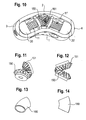
Fig. 1 . - Fig. 3
- shows a perspective top view of the intervertebral implant of
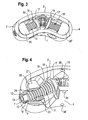
Fig. 1 and 2 with the upper engagement member omitted. - Fig. 4
- shows a detail of
Fig. 3 in an enlarged view, partly in section. - Fig. 5
- shows the drive mechanism of the implant shown in
Fig. 3 . - Fig. 6
- shows a perspective front view of a coupling member of the coupling mechanism shown in
Fig. 5 . - Fig. 7
- shows a top view of the coupling member of
Fig. 6 . - Fig. 8
- shows a side view of the coupling member of
Fig. 6 . - Fig. 9
- shows another side view of the coupling member of
Fig. 6 . - Fig. 10
- shows a perspective view of the implant according to
Fig. 1 and 2 with a modified coupling mechanism and the upper engagement member being omitted. - Fig. 11
- shows a detail of the modified coupling mechanism.
- Fig. 12
- shows a side view of the coupling mechanism shown in
Fig. 11 . - Fig. 13
- shows a perspective top view of another modified coupling mechanism.
- Fig. 14
- shows a top view of the member of
Fig. 13 . - Fig. 15
- shows a side view of an engagement member of the implant in a first embodiment.
- Fig. 16
- shows a perspective top view of the engagement member of
Fig. 15 - Fig. 17
- shows a perspective bottom view of the engagement member of
Fig. 15 . - Fig. 18
- shows a perspective view of an outer portion of the engagement member of
Fig. 15 . - Fig. 19
- shows a side view of an engagement member of the implant according to a second embodiment.
- Fig. 20
- shows a perspective top view of the engagement member of
Fig. 19 . - Fig. 21
- shows a front view of the expandable intervertebral implant with the engagement members in a retracted position.
- Fig. 22
- shows a front view of the expandable intervertebral implant with the engagement members in an expanded position.
- Fig. 23
- shows an implant partially in section with the engagement members of
Fig. 19 in the retracted condition. - Fig. 24
- shows an implant partially in section with the engagement members of
Fig. 19 in the expanded position. - Fig. 25a to 25e
- show steps of assembling the intervertebral implant.
- As shown in
Fig. 1 to 7 the expandable intervertebral implant comprisesfront wall 1, aback wall 2 spaced apart from the front wall, andfirst side wall 3 connecting thefront wall 1 and theback wall 2 at their one end as well as asecond side wall 4 opposite to the first side wall for connecting the front wall and the back wall at their opposite other ends. As best shown inFig. 1 , the bottom and top faces are open so that the four walls define acavity 5 having an open bottom and an open top. Thefront wall 1 and theback wall 2 have approximately the same length and are curved in approximately the same direction. Thesides walls Figs. 21 to 24 ) in order to be adapted to a corresponding depressed portion of the end plate of the vertebral body. Thefront wall 1 and theback wall 2 have preferably a plurality ofapertures 6 which have a diamond shape in the embodiment shown. However, the shape of the apertures can also be circular, oval-shaped or otherwise shaped. - As shown in particular in
Fig. 1 and 2 , theside walls bore 7, 7' at approximately their center. As can be seen best inFig. 4 thebore 7 and the corresponding opposite bore 7' each have a first portion 8 with a first bore diameter adjacent to the outside of the side wall, respectively, and a following second portion 9 which opens into thecavity 5 and which has a second bore diameter which is slightly less than the first bore diameter. Thereby, the second portion 9 defines a shoulder. - A bearing member (or bearing journal) 10, 10', respectively is inserted into the
bore 7, 7'. Each bearingmember 10, 10' has a first cylindrical portion with a first outer diameter and adjacent thereto a second cylindrical portion with a second outer diameter matching the inner diameters of the first portion 8 and the second portion 9 of thebore 7, 7', so that the bearing member rests on the shoulder. The size of the bearingmember 10, 10' is such, that the bearingmember 10, 10' is held in thebore 7, 7', respectively, by press-fitting. - The implant further comprises two threaded
spindles 11, 11', each having a firstcylindrical end 12, 12' with arecess 13, 13', preferably a hexagon recess, at the free end for engagement with a tool (not shown). The outer diameter of the cylindricalfirst end 12, 12' is slightly smaller than the inner diameter of thebearing 10, 10' so thatfirst end 12, 12' of the spindle can be inserted into thebearing 10, 10' and can be rotatably held therein. Each spindle further has a cylindricalsecond end 14, 14', opposite to thefirst end 12, 12'. - The thread pitches of the threaded
spindles 11, 11' are opposite to each other. The length of the threaded spindles is such that when the spindles are held in thebearings 10, 10' and project into thecavity 5, the second ends 14, 14' of the spindles do not touch each other. - As can be seen in particular in
Fig. 3 to 5 the threadedspindles 11, 11' are connected with the second ends 14, 14' via acoupling member 15. Thecoupling member 15 in the embodiment shown inFig. 1 to 7 is designed as a curved tubeportion having slits 16 extending in a circumferential direction. The slits are offset from each other in such a way that the slits of one circumferential line cover at least such portions of an adjacent circumferential line, where no slit is provided. The inner diameter of thecoupling member 15 is such that thecoupling member 15 can be connected to thecylindrical end portions 14, 14' of the threaded spindles for example by means of a press-fit connection. The curvature and length of the coupling member is such that it is adapted to the angle α which the longitudinal axis L, L' of the threadedspindles 11, 11' enclose with each other. That means the curvature of thecoupling member 15 corresponds substantially to the curvature of thefront wall 1 and theback wall 2 of the implant. The number, width and length of theslits 16 are selected so as to provide a desired bending flexibility to the tube while providing sufficient torsional stiffness. - As can be seen in
Fig. 3 acircular flange 17, 17' can be provided at theend 14, 14' of eachspindle 11, 11' to provide a stop the function of which will be described later. Theflange 17, 17' has aprojection 18 on opposite sides which rests on ashoulder 19 provided at the inner side of thefront wall 1 and theback wall 2, respectively. Theflange 17, 17' also provides for a guidance and/or support for the spindles and the coupling member. - As can be seen in particular in
Fig. 1 and3 to 5 awedge member 20, 20' is provided on each threadedspindle 11, 11'. Each wedge member is defined by atop face 21, 21' and anopposite bottom face 22, 22' which include an angle with each other to define the wedge-shape. Eachwedge member 20, 20' comprises a flatfront wall 23, 23' and a curved rear wall and flat side walls. The flatfront wall 23, 23' and thetop wall 21, 21' and thebottom wall 22, 22' are arranged such that the distance increases between top wall and bottom wall in a direction away from the front wall. Thewedge member 20, 20' comprises a threaded bore having an internal thread corresponding to the external thread of the threadedspindle 11, 11', respectively. Thewedge members 20, 20' are screwed onto the corresponding threadedspindles 11, 11' in such a position that their corresponding top faces 21, 21' and bottom faces 22, 22' are inclined towards each other. As can be seen in particular inFig. 3 , the back walls of the wedge members are curved in such a way that they fit to the curvature of the inner side of theside walls - As shown best in
Fig. 1, 2 and15 to 18 afirst engagement member 30 and a second engagement member 30', respectively, is placed between the mutually inclined top faces 21, 21' and mutually inclined bottom faces 22, 22', which will be referred to as wedge faces, of thewedge members 20, 20'. Eachengagement member 30, 30' has on its lower face facing the wedge members two mutually inclined slopingsurfaces surfaces inclined surfaces engagement member 30, 30' comprises a substantially curvedcylindrical recess 33, 33' which is sized so as to be able to accommodate thecoupling member 15 including theflanges 17, 17'. Therecess 33, 33' runs out into theinclined surfaces engagement members 30, 30' and the wedge faces of thewedge members 20, 20' can slide onto each other. To enhance the sliding capability, the faces can be coated with a coating or can be polished. - As can be seen in particular in
Fig. 16 and 17 the contour of the engagement members is approximately banana-shaped or kidney-shaped and corresponds to the contour of the implant body as shown inFig. 1 and 2 . Thetop surface 34 of theengagement member 30 has in the embodiment shown aright portion 34a and aleft portion 34b which have a slight inclination with respect to each other, the inclination being opposite to the inclination of theinclined surfaces inclined portions 34a', 34b' (not shown). Thetop surface 34 further has anengagement structure 35 which can be designed as teeth projecting from the surface or as ribs or as any other structure which is suitable for engagement with the surface of the end plates of the vertebral body. - As can be seen in
Fig. 1, 2 and15, 16 eachengagement member 30, 30' comprises a substantiallyU-shaped slit 36, 36' extending from thetop surface 34, 34' to a certain distance therefrom. Thefront wall 1 and theback wall 2 each comprise bores 38, 38' located in the center between the side walls, one in the upper half and one in the lower half. Twopins 39, 39' extend throughopposite bores 38 across thecavity 5. Thepins 39, 39' engage theU-shaped slits 36 of theengagement members 30, 30', respectively. By means of this, a stop is formed preventing falling-out of theengagement members 30, 30'. The U-shaped slits 36 also form a guidance for theengagement members 30,30'. - The arrangement of the
pins 39, 39' and the depth of theU-shaped slits 36, 36' are matched to each other such that the maximum heights of outward movement of the respective engagement members over the bottom face and the top face is determined by the relative position of thepin 39, 39' and the depth of theslits 36. - The dimensions of the
wedge members 20, 20', the threadedspindles 11, 11' and theengagement members 30, 30' as well as the pitch of the threads is designed so as to allow the engagement members to be displaced from a first position shown inFig. 21 and23 in which thetop surface 34, 34' is located in thecavity 5 to a second position shown inFig. 22 and24 in which thetop surface 34, 34' projects above thecavity 5 of the implant. - The implant is manufactured from a biocompatible material, such as titanium, a biocompatible plastic material or other biocompatible materials. The
coupling member 15 is for example manufactured from stainless steel or titanium to provide sufficient strength. - In operation, first, the
wedge members 20, 20' are brought into the position shown inFig. 3 wherein the back walls are in contact with the inner sides of theside walls 34 of the implant by rotating one of the threaded spindles. This causes eachengagement member 30, 30' to take up its lowermost position wherein theengagement structure 35 of thetop surface 34, 34' does not project beyond thecavity 5 of the implant. The implant can therefore easily be inserted into the area between two vertebrae and there is no risk of injuring the soft parts of the end plates of the vertebrae. Since the contour of the implant is approximately banana-shaped the insertion is facilitated compared to the insertion of a rectangular implant. The implant can be inserted in such a way that the front wall is oriented in the dorsal direction and the back wall is oriented in the ventral direction and the side walls are oriented laterally. The indication of the front, back and side wall does not limit the use of the implant to the particular way of insertion and is merely for the distinction of the walls with respect to each other. After having correctly positioned the implant between the vertebrae, the twowedge members 20, 20' are moved towards each other by engaging one of the threadedspindles 11, 11' by accessing it from one of theside walls recess 13, 13' of the spindle. By rotating one of the threaded spindles the rotational movement is transferred by thecoupling member 15 to the other threaded spindle. In the embodiment shown inFig. 1 to 7 , the coupling member has due to itsslits 16 which form weakened portions, a bending capability with sufficient torsional stiffness which allows to transfer the rotational motion of one spindle to the other spindle. By rotating one of the spindles the mutually inclined wedge surfaces 21, 22 and 21', 22' of the twoopposed wedge members 20, 20' exert a force onto theinclined surfaces corresponding engagement members 30, 30' to raise the same until theengagement structure 35 of thetop surface 34, 34' projects out of thecavity 5 to thereby engage the end plates of the respective vertebrae. The lifting movement of theengagement members 30, 30' is limited by the stop formed by thepins 39, 39' as particularly shown inFig. 24 . Theflanges 17, 17' can also provide a stop for the movement of the wedge members. - The transmission of the rotation of the tool through one threaded spindle to the other threaded spindle and from the wedge members to the engagement members allows a precise adjustment of the expansion of the engagement members and allows for an individual adaptation of the implant to the anatomical shape of the end plates of the vertebrae of the individual patient.
- The threaded spindles prevent the engagement members from becoming loose by themselves. The
engagement members 30, 30' can be retracted only by backward rotation using a tool whereby the pressure exerted by the vertebrae onto the engagement members forces the engagement members back into thecavity 5 of the implant. This releases the engagement structure from the end plates of the vertebrae. -
Fig. 19 and 20 show an alternative embodiment of the engagement member. Theengagement member 300 differs from theengagement member 30, 30' in that it has two opposedslanted surfaces U-shaped recess 36 the inclination of which can be parallel to the inclination of theinclined surfaces engagement member 300. Theslanted surfaces - A further modification of the coupling mechanism to transfer the rotational movement from one spindle to the other spindle is shown in
Fig. 10 to 12 . The coupling mechanism can be formed by a bevel gear drive comprising twopinions spindles 11, 11'. - A further modified embodiment of the coupling mechanism for transferring the rotational movement of one spindle to the other spindle is shown in
Fig. 13 and 14 . It comprises aflexible tube 160 which has a curvature and dimensions similar to thecoupling member 15 shown inFig. 1 to 7 and which is sized so as to be press-fit connected to theends 14, 14' of the spindles. Thecoupling member 160 transfers the rotational movement by a deformation of the flexible material. Thecoupling member 160 can be made for example, from nitinol or flexible plastic material with bending flexibility but torsional stiffness. -
Fig. 25a to 25e show steps for assembly of the implant. In the first step shown inFig. 25a , first, the first spindle with the corresponding wedge-member screwed thereon is inserted into the cavity and the corresponding bearing. As a next step the couplingmember 15 is connected to the first spindle. Then, the second wedge member is inserted, the second spindle guided through the second bore and screwed through the second wedge member until it can be connected with the flange of the coupling member. Then, the second bearing is inserted (Figs. 25a and 25b ). As shown inFig. 25c and 25d , when the spindles including the wedge members are inserted and coupled by the coupling member the engagement members can be inserted and thepins 39, 39' put through thebores Fig. 25e . - Although the walls are described as front wall, back wall and side walls, this is not to be understood as a limitation for the orientation of the implant between the vertebrae. The shape of the implant is not restricted to a banana shape or kidney shape. For example, the shape can be ring-shaped or a quarter ring or a half ring or any other shape.
- It is also conceivable that more than two wedge members on more than two supporting members are provided enclosing an angle with each other. For example three support spindles enclosing an angle of 120° with each other and three adjustment or wedge members can be provided.
- Other coupling mechanisms are conceivable, for example a corrugated tube, a cardan joint or a bowden cable. Even non mechanical couplings, for example, a magnetic coupling is possible.
Claims (17)
- An expandable intervertebral implant comprising:a front wall (1),a back wall (2) spaced apart from the front wall, andtwo side walls (3, 4) connecting the front wall (1) and the back wall (2) at their respective ends,the walls defining a space (5),a bottom face,a top face,at least one engagement member (30, 30') with an engagement surface (34, 34') for engagement with the end plate of a vertebral body,a first adjusting element (20) and a second adjusting element (20') which are supported by a first support member (11) and a second support member (11'), respectively, and which cooperate with the respective support member such that the engagement member (30, 30') is reciprocally movable between a first end position wherein the engagement surface (34, 34') does not project beyond the bottom face or the top face and a second end position wherein the engagement surface (34, 34') at least partially projects outwardly beyond the bottom face or the top face,wherein the first and the second support members (11, 11') are coupled by a coupling mechanism (15; 150, 151; 160).
- The intervertebral implant of claim 1, wherein the first support member (11) is rotatable and the second support member (11') is rotatable and the coupling mechanism (15; 150, 151; 160) transfers the rotation of the first support member to the second support member.
- The intervertebral implant of claim 2, wherein the axis of rotation of the first support member (11) and the axis of rotation of the second support member (11') include an angle which is different from zero.
- The intervertebral implant of one of claims 1 to 3, wherein the coupling mechanism (15; 150, 151; 160) comprises a rotational coupling.
- The intervertebral implant of one of claims 1 to 4, wherein the coupling mechanism comprises a flexible tube (15; 160).
- The intervertebral implant of claim 4 or 5, wherein the coupling mechanism comprises a bevel gear drive, a tube made of rigid material with bending zones or a flexible tube drive.
- The intervertebral implant of one of claims 1 to 6, wherein the support members (11, 11') are formed as first and second threaded spindle (11, 11') having opposite thread pitch.
- The intervertebral implant of one of claims 1 to 7, wherein the adjusting elements (20, 20') are wedge members, said wedge members operating to move the engagement member (30, 30').
- The intervertebral implant according to claim 7, wherein the adjusting elements (20, 20') are formed as wedge members and one end (12) of the first treaded spindle (11) being rotationally supported in the first side wall (3), one end (12') of the second threaded spindle (11') being rotationally supported in the second side wall (4) and the other ends (14, 14') being rotationally coupled to each other, and
wherein the two wedge members are supported within the space (15) in such a manner, that, upon rotation of the first or the second threaded spindle in one direction a distance between the wedge members decreases and upon rotation of the threaded spindle in an opposite direction the distance between the wedge members increases, and said wedge members operate to move the engagement element. - The intervertebral implant according to one of claims 7 and 8, wherein the engagement member (30, 30') has two inclined surfaces (31, 32; 31', 32') on a side opposite to said engagement surface (34, 34') and wherein the wedge members engage the inclined surfaces.
- The intervertebral implant according to one of claims 1 to 10, wherein at least the front wall (1) or the back wall (2) is curved.
- The intervertebral implant according to one of claims 1 to 11, wherein the walls of the implant are curved in such a way that the contour of the space which is formed by the walls is substantially banana-shaped.
- The intervertebral implant according to one of claims 1 to 12, wherein the engagement surface (34, 34') of the engagement member (30, 30') comprises an engagement structure (35) for penetration into an adjacent bone material.
- An intervertebral implant according to one of claims 1 to 12, further comprising a stop (36, 39) that limits the outward movement of the engagement member (30, 30').
- The intervertebral implant according to one of claims 1 to 14, comprising two engagement members (30, 30') movable in opposite directions.
- The intervertebral implant according to one of claims 1 to 15, wherein the first support member (11) and the second support member (11') are each supported in one of said walls (1, 2, 3, 4).
- The intervertebral implant according to one of claims 1 to 16, wherein the adjusting elements (20, 20') are each guided by two of the walls (1, 2, 3, 4)
Priority Applications (11)
| Application Number | Priority Date | Filing Date | Title |
|---|---|---|---|
| EP06024332A EP1925272B1 (en) | 2006-11-23 | 2006-11-23 | Expandable intervertebral implant |
| DE602006011762T DE602006011762D1 (en) | 2006-11-23 | 2006-11-23 | Expandable intervertebral implant |
| ES06024332T ES2339472T3 (en) | 2006-11-23 | 2006-11-23 | EXPANSIBLE INTERVERTEBRAL IMPLANT. |
| TW096143631A TWI422361B (en) | 2006-11-23 | 2007-11-19 | Expandable intervertebral implant |
| KR1020070118545A KR101465187B1 (en) | 2006-11-23 | 2007-11-20 | Expandable Intervertebral Implant |
| CN2007101927838A CN101185594B (en) | 2006-11-23 | 2007-11-20 | Expandable intervertebral implant |
| JP2007300394A JP5222536B2 (en) | 2006-11-23 | 2007-11-20 | Extensible intervertebral implant |
| US11/944,580 US8366777B2 (en) | 2006-11-23 | 2007-11-23 | Expandable intervertebral implant |
| US13/732,032 US8702798B2 (en) | 2006-11-23 | 2012-12-31 | Expandable intervertebral implant |
| US14/176,871 US9662223B2 (en) | 2006-11-23 | 2014-02-10 | Expandable intervertebral implant |
| US15/583,665 US9980823B2 (en) | 2006-11-23 | 2017-05-01 | Expandable intervertebral implant |
Applications Claiming Priority (1)
| Application Number | Priority Date | Filing Date | Title |
|---|---|---|---|
| EP06024332A EP1925272B1 (en) | 2006-11-23 | 2006-11-23 | Expandable intervertebral implant |
Publications (2)
| Publication Number | Publication Date |
|---|---|
| EP1925272A1 true EP1925272A1 (en) | 2008-05-28 |
| EP1925272B1 EP1925272B1 (en) | 2010-01-13 |
Family
ID=37950876
Family Applications (1)
| Application Number | Title | Priority Date | Filing Date |
|---|---|---|---|
| EP06024332A Active EP1925272B1 (en) | 2006-11-23 | 2006-11-23 | Expandable intervertebral implant |
Country Status (8)
| Country | Link |
|---|---|
| US (4) | US8366777B2 (en) |
| EP (1) | EP1925272B1 (en) |
| JP (1) | JP5222536B2 (en) |
| KR (1) | KR101465187B1 (en) |
| CN (1) | CN101185594B (en) |
| DE (1) | DE602006011762D1 (en) |
| ES (1) | ES2339472T3 (en) |
| TW (1) | TWI422361B (en) |
Cited By (31)
| Publication number | Priority date | Publication date | Assignee | Title |
|---|---|---|---|---|
| EP2476396A1 (en) * | 2011-01-12 | 2012-07-18 | Ebi, Llc | Expandable spinal implant device |
| WO2012140218A1 (en) * | 2011-04-15 | 2012-10-18 | Z-Medical Gmbh & Co. Kg | Intervertebral implant and insertion device |
| US9693876B1 (en) | 2012-03-30 | 2017-07-04 | Ali H. MESIWALA | Spinal fusion implant and related methods |
| US9889019B2 (en) | 2013-08-29 | 2018-02-13 | Spineex, Inc. | Expandable and adjustable lordosis interbody fusion system |
| EP3345575A1 (en) * | 2017-01-06 | 2018-07-11 | Ke Ling Biotech Limited | Expandable spinal interbody cage |
| US10940016B2 (en) | 2017-07-05 | 2021-03-09 | Medos International Sarl | Expandable intervertebral fusion cage |
| US10966840B2 (en) | 2010-06-24 | 2021-04-06 | DePuy Synthes Products, Inc. | Enhanced cage insertion assembly |
| US10973652B2 (en) | 2007-06-26 | 2021-04-13 | DePuy Synthes Products, Inc. | Highly lordosed fusion cage |
| US11273050B2 (en) | 2006-12-07 | 2022-03-15 | DePuy Synthes Products, Inc. | Intervertebral implant |
| US11344424B2 (en) | 2017-06-14 | 2022-05-31 | Medos International Sarl | Expandable intervertebral implant and related methods |
| US11426286B2 (en) | 2020-03-06 | 2022-08-30 | Eit Emerging Implant Technologies Gmbh | Expandable intervertebral implant |
| US11426290B2 (en) | 2015-03-06 | 2022-08-30 | DePuy Synthes Products, Inc. | Expandable intervertebral implant, system, kit and method |
| US11446161B2 (en) | 2019-08-15 | 2022-09-20 | Adcura, Inc. | Translating dual axis adjustable interbody fusion spinal system |
| US11446155B2 (en) | 2017-05-08 | 2022-09-20 | Medos International Sarl | Expandable cage |
| US11446156B2 (en) | 2018-10-25 | 2022-09-20 | Medos International Sarl | Expandable intervertebral implant, inserter instrument, and related methods |
| US11452607B2 (en) | 2010-10-11 | 2022-09-27 | DePuy Synthes Products, Inc. | Expandable interspinous process spacer implant |
| US11452614B2 (en) | 2013-08-29 | 2022-09-27 | Adcura, Inc. | Expandable and adjustable lordosis interbody fusion system |
| US11497619B2 (en) | 2013-03-07 | 2022-11-15 | DePuy Synthes Products, Inc. | Intervertebral implant |
| US11510788B2 (en) | 2016-06-28 | 2022-11-29 | Eit Emerging Implant Technologies Gmbh | Expandable, angularly adjustable intervertebral cages |
| US11596523B2 (en) | 2016-06-28 | 2023-03-07 | Eit Emerging Implant Technologies Gmbh | Expandable and angularly adjustable articulating intervertebral cages |
| US11602438B2 (en) | 2008-04-05 | 2023-03-14 | DePuy Synthes Products, Inc. | Expandable intervertebral implant |
| US11607321B2 (en) | 2009-12-10 | 2023-03-21 | DePuy Synthes Products, Inc. | Bellows-like expandable interbody fusion cage |
| US11612491B2 (en) | 2009-03-30 | 2023-03-28 | DePuy Synthes Products, Inc. | Zero profile spinal fusion cage |
| US11648132B2 (en) | 2019-09-24 | 2023-05-16 | Adcura, Inc | Surgical instrument for operating spinal implant system with dual axis adjustability and method of operating same |
| US11654033B2 (en) | 2010-06-29 | 2023-05-23 | DePuy Synthes Products, Inc. | Distractible intervertebral implant |
| US11660205B2 (en) | 2019-08-15 | 2023-05-30 | Adcura, Inc. | Dual-axis adjustable spinal systems and interbody fusion devices with fixation |
| US11737881B2 (en) | 2008-01-17 | 2023-08-29 | DePuy Synthes Products, Inc. | Expandable intervertebral implant and associated method of manufacturing the same |
| US11752009B2 (en) | 2021-04-06 | 2023-09-12 | Medos International Sarl | Expandable intervertebral fusion cage |
| US11857432B2 (en) | 2020-04-13 | 2024-01-02 | Life Spine, Inc. | Expandable implant assembly |
| US11896494B2 (en) | 2017-07-10 | 2024-02-13 | Life Spine, Inc. | Expandable implant assembly |
| US11911287B2 (en) | 2010-06-24 | 2024-02-27 | DePuy Synthes Products, Inc. | Lateral spondylolisthesis reduction cage |
Families Citing this family (188)
| Publication number | Priority date | Publication date | Assignee | Title |
|---|---|---|---|---|
| US7041309B2 (en) | 2002-06-13 | 2006-05-09 | Neuropro Technologies, Inc. | Spinal fusion using an HMG-CoA reductase inhibitor |
| US6793678B2 (en) | 2002-06-27 | 2004-09-21 | Depuy Acromed, Inc. | Prosthetic intervertebral motion disc having dampening |
| US7828849B2 (en) | 2003-02-03 | 2010-11-09 | Warsaw Orthopedic, Inc. | Expanding interbody implant and articulating inserter and method |
| CN1774220A (en) | 2003-02-14 | 2006-05-17 | 德普伊斯派尔公司 | In-situ formed intervertebral fusion device and method |
| US20040267367A1 (en) | 2003-06-30 | 2004-12-30 | Depuy Acromed, Inc | Intervertebral implant with conformable endplate |
| US8016829B2 (en) | 2004-02-09 | 2011-09-13 | Depuy Spine, Inc. | Systems and methods for spinal surgery |
| US8636802B2 (en) | 2004-03-06 | 2014-01-28 | DePuy Synthes Products, LLC | Dynamized interspinal implant |
| US8992618B2 (en) | 2004-04-26 | 2015-03-31 | DePuy Synthes Products, LLC | Intervertebral prosthesis or disk prosthesis |
| FR2871366A1 (en) | 2004-06-09 | 2005-12-16 | Ceravic Soc Par Actions Simpli | PROSTHETIC EXPANSIBLE BONE IMPLANT |
| WO2006034436A2 (en) | 2004-09-21 | 2006-03-30 | Stout Medical Group, L.P. | Expandable support device and method of use |
| US8597360B2 (en) | 2004-11-03 | 2013-12-03 | Neuropro Technologies, Inc. | Bone fusion device |
| US8092528B2 (en) | 2005-05-27 | 2012-01-10 | Depuy Spine, Inc. | Intervertebral ligament having a helical bone fastener |
| WO2007009107A2 (en) | 2005-07-14 | 2007-01-18 | Stout Medical Group, P.L. | Expandable support device and method of use |
| US9028550B2 (en) | 2005-09-26 | 2015-05-12 | Coalign Innovations, Inc. | Selectively expanding spine cage with enhanced bone graft infusion |
| US20070162132A1 (en) | 2005-12-23 | 2007-07-12 | Dominique Messerli | Flexible elongated chain implant and method of supporting body tissue with same |
| JP5542273B2 (en) | 2006-05-01 | 2014-07-09 | スタウト メディカル グループ,エル.ピー. | Expandable support device and method of use |
| US8034110B2 (en) | 2006-07-31 | 2011-10-11 | Depuy Spine, Inc. | Spinal fusion implant |
| US9526525B2 (en) | 2006-08-22 | 2016-12-27 | Neuropro Technologies, Inc. | Percutaneous system for dynamic spinal stabilization |
| US8142479B2 (en) * | 2007-05-01 | 2012-03-27 | Spinal Simplicity Llc | Interspinous process implants having deployable engagement arms |
| US8273124B2 (en) | 2007-05-17 | 2012-09-25 | Depuy Spine, Inc. | Self-distracting cage |
| ATE524126T1 (en) * | 2007-07-03 | 2011-09-15 | Sota Orthopaedics Ltd | BOLT DEVICE |
| US20090088789A1 (en) | 2007-09-28 | 2009-04-02 | O'neil Michael J | Balloon With Shape Control For Spinal Procedures |
| US8932355B2 (en) | 2008-02-22 | 2015-01-13 | Coalign Innovations, Inc. | Spinal implant with expandable fixation |
| US8992620B2 (en) | 2008-12-10 | 2015-03-31 | Coalign Innovations, Inc. | Adjustable distraction cage with linked locking mechanisms |
| US20100145455A1 (en) | 2008-12-10 | 2010-06-10 | Innvotec Surgical, Inc. | Lockable spinal implant |
| US8267939B2 (en) | 2008-02-28 | 2012-09-18 | Stryker Spine | Tool for implanting expandable intervertebral implant |
| WO2009125242A1 (en) * | 2008-04-08 | 2009-10-15 | Vexim | Apparatus for restoration of the spine and methods of use thereof |
| US20100010633A1 (en) * | 2008-07-10 | 2010-01-14 | Kyphon Sarl | Deployable Arc Fusion Cage and Methods Associated Therewith |
| EP2326281A4 (en) * | 2008-08-13 | 2013-05-29 | Smed Ta Td Llc | Orthopaedic implant with porous structural member |
| US10842645B2 (en) | 2008-08-13 | 2020-11-24 | Smed-Ta/Td, Llc | Orthopaedic implant with porous structural member |
| US20100042213A1 (en) | 2008-08-13 | 2010-02-18 | Nebosky Paul S | Drug delivery implants |
| US9700431B2 (en) * | 2008-08-13 | 2017-07-11 | Smed-Ta/Td, Llc | Orthopaedic implant with porous structural member |
| US9616205B2 (en) | 2008-08-13 | 2017-04-11 | Smed-Ta/Td, Llc | Drug delivery implants |
| JP5687622B2 (en) | 2008-08-29 | 2015-03-18 | スメド−ティーエイ/ティーディー・エルエルシー | Orthopedic implant |
| US8147554B2 (en) * | 2008-10-13 | 2012-04-03 | Globus Medical, Inc. | Intervertebral spacer |
| US8545566B2 (en) * | 2008-10-13 | 2013-10-01 | Globus Medical, Inc. | Articulating spacer |
| US20100211176A1 (en) | 2008-11-12 | 2010-08-19 | Stout Medical Group, L.P. | Fixation device and method |
| US20100204795A1 (en) | 2008-11-12 | 2010-08-12 | Stout Medical Group, L.P. | Fixation device and method |
| ES2659719T3 (en) | 2009-03-12 | 2018-03-19 | Vexim | Apparatus for bone restoration of the spine |
| US9861399B2 (en) | 2009-03-13 | 2018-01-09 | Spinal Simplicity, Llc | Interspinous process implant having a body with a removable end portion |
| US9757164B2 (en) | 2013-01-07 | 2017-09-12 | Spinal Simplicity Llc | Interspinous process implant having deployable anchor blades |
| US9220547B2 (en) | 2009-03-27 | 2015-12-29 | Spinal Elements, Inc. | Flanged interbody fusion device |
| US9642722B2 (en) | 2009-07-02 | 2017-05-09 | Atlas Spine, Inc. | Intervertebral expandable spacer |
| BRPI1014714B1 (en) | 2009-07-06 | 2020-05-19 | Synthes Gmbh | expandable bone fixation set |
| US10245159B1 (en) | 2009-09-18 | 2019-04-02 | Spinal Surgical Strategies, Llc | Bone graft delivery system and method for using same |
| US10973656B2 (en) | 2009-09-18 | 2021-04-13 | Spinal Surgical Strategies, Inc. | Bone graft delivery system and method for using same |
| US8906028B2 (en) | 2009-09-18 | 2014-12-09 | Spinal Surgical Strategies, Llc | Bone graft delivery device and method of using the same |
| US11344430B2 (en) * | 2009-10-15 | 2022-05-31 | Globus Medical, Inc. | Expandable fusion device and method of installation thereof |
| US9155628B2 (en) * | 2009-10-15 | 2015-10-13 | Globus Medical, Inc. | Expandable fusion device and method of installation thereof |
| US8062375B2 (en) * | 2009-10-15 | 2011-11-22 | Globus Medical, Inc. | Expandable fusion device and method of installation thereof |
| US8709086B2 (en) | 2009-10-15 | 2014-04-29 | Globus Medical, Inc. | Expandable fusion device and method of installation thereof |
| US9028553B2 (en) | 2009-11-05 | 2015-05-12 | DePuy Synthes Products, Inc. | Self-pivoting spinal implant and associated instrumentation |
| US8894712B2 (en) * | 2010-01-11 | 2014-11-25 | Innova Spinal Technologies, Llc | Expandable intervertebral implant and associated surgical method |
| US8894711B2 (en) * | 2010-01-11 | 2014-11-25 | Innova Spinal Technologies, Llc | Expandable intervertebral implant and associated surgical method |
| US8795366B2 (en) * | 2010-01-11 | 2014-08-05 | Innova Spinal Technologies, Llc | Expandable intervertebral implant and associated surgical method |
| US8353963B2 (en) * | 2010-01-12 | 2013-01-15 | Globus Medical | Expandable spacer and method for use thereof |
| US9101409B2 (en) * | 2010-03-09 | 2015-08-11 | National University Corporation Kobe University | Inter-spinous process implant |
| CA2793185C (en) | 2010-03-16 | 2019-02-12 | Pinnacle Spine Group, Llc | Intervertebral implants and graft delivery systems and methods |
| US8535380B2 (en) * | 2010-05-13 | 2013-09-17 | Stout Medical Group, L.P. | Fixation device and method |
| US8317866B2 (en) * | 2010-06-02 | 2012-11-27 | Warsaw Orthopedic, Inc. | System and methods for a laterally expanding implant |
| EP2608747A4 (en) | 2010-08-24 | 2015-02-11 | Flexmedex Llc | Support device and method for use |
| US9855151B2 (en) * | 2010-09-03 | 2018-01-02 | Globus Medical, Inc | Expandable fusion device and method of installation thereof |
| US9474625B2 (en) * | 2010-09-03 | 2016-10-25 | Globus Medical, Inc | Expandable fusion device and method of installation thereof |
| US20120078372A1 (en) | 2010-09-23 | 2012-03-29 | Thomas Gamache | Novel implant inserter having a laterally-extending dovetail engagement feature |
| US9149286B1 (en) | 2010-11-12 | 2015-10-06 | Flexmedex, LLC | Guidance tool and method for use |
| US8740980B2 (en) | 2011-01-27 | 2014-06-03 | Warsaw Orthopedic, Inc. | Expandable medical implant |
| US8394129B2 (en) | 2011-03-10 | 2013-03-12 | Interventional Spine, Inc. | Method and apparatus for minimally invasive insertion of intervertebral implants |
| US8518087B2 (en) | 2011-03-10 | 2013-08-27 | Interventional Spine, Inc. | Method and apparatus for minimally invasive insertion of intervertebral implants |
| ES2592270T3 (en) * | 2011-03-11 | 2016-11-29 | FBC Device ApS | Spinal implant |
| AU2012231108B2 (en) | 2011-03-22 | 2015-10-22 | DePuy Synthes Products, LLC | Universal trial for lateral cages |
| CN103841909B (en) | 2011-04-07 | 2017-02-15 | 维克辛姆公司 | Expandable orthopedic device |
| US9066813B2 (en) * | 2011-06-03 | 2015-06-30 | Biomet Spine, Llc | Unidirectional dynamic interbody fusion device and method of use |
| EP2535021B1 (en) * | 2011-06-14 | 2015-10-14 | Biedermann Technologies GmbH & Co. KG | Intervertebral implant |
| WO2012174526A1 (en) * | 2011-06-17 | 2012-12-20 | Mcafee Paul C | Expandable spinal implant and flexible driver |
| WO2013006669A2 (en) * | 2011-07-05 | 2013-01-10 | Expanding Orthopedics Inc. | Bone structural device |
| WO2013023098A1 (en) * | 2011-08-09 | 2013-02-14 | Neuropro Spinal Jaxx Inc. | Bone fusion device, apparatus and method |
| US10292830B2 (en) | 2011-08-09 | 2019-05-21 | Neuropro Technologies, Inc. | Bone fusion device, system and method |
| US10420654B2 (en) | 2011-08-09 | 2019-09-24 | Neuropro Technologies, Inc. | Bone fusion device, system and method |
| EP2729092B1 (en) | 2011-08-16 | 2016-09-21 | Stryker European Holdings I, LLC | Expandable implant |
| JP2014529445A (en) | 2011-08-23 | 2014-11-13 | フレックスメデックス,エルエルシー | Tissue removal apparatus and method |
| US9248028B2 (en) | 2011-09-16 | 2016-02-02 | DePuy Synthes Products, Inc. | Removable, bone-securing cover plate for intervertebral fusion cage |
| US8864833B2 (en) * | 2011-09-30 | 2014-10-21 | Globus Medical, Inc. | Expandable fusion device and method of installation thereof |
| US9380932B1 (en) | 2011-11-02 | 2016-07-05 | Pinnacle Spine Group, Llc | Retractor devices for minimally invasive access to the spine |
| US9233007B2 (en) * | 2012-02-13 | 2016-01-12 | Blue Tip Biologics, Llc | Expandable self-anchoring interbody cage for orthopedic applications |
| WO2013148176A1 (en) * | 2012-03-28 | 2013-10-03 | Innova Spinal Technologies, Llc | Expandable intervertebral implant and associated surgical method |
| US9381011B2 (en) * | 2012-03-29 | 2016-07-05 | Depuy (Ireland) | Orthopedic surgical instrument for knee surgery |
| US10159583B2 (en) | 2012-04-13 | 2018-12-25 | Neuropro Technologies, Inc. | Bone fusion device |
| US9532883B2 (en) | 2012-04-13 | 2017-01-03 | Neuropro Technologies, Inc. | Bone fusion device |
| US9622876B1 (en) * | 2012-04-25 | 2017-04-18 | Theken Spine, Llc | Expandable support device and method of use |
| US8940052B2 (en) | 2012-07-26 | 2015-01-27 | DePuy Synthes Products, LLC | Expandable implant |
| US20140067069A1 (en) | 2012-08-30 | 2014-03-06 | Interventional Spine, Inc. | Artificial disc |
| US8663332B1 (en) | 2012-12-13 | 2014-03-04 | Ouroboros Medical, Inc. | Bone graft distribution system |
| US10022245B2 (en) | 2012-12-17 | 2018-07-17 | DePuy Synthes Products, Inc. | Polyaxial articulating instrument |
| US9974664B2 (en) | 2013-01-24 | 2018-05-22 | Biospine, Llc | Adjustable interbody fusion device and method of use |
| US9782265B2 (en) * | 2013-02-15 | 2017-10-10 | Globus Medical, Inc | Articulating and expandable vertebral implant |
| US9492288B2 (en) | 2013-02-20 | 2016-11-15 | Flexuspine, Inc. | Expandable fusion device for positioning between adjacent vertebral bodies |
| US10117754B2 (en) * | 2013-02-25 | 2018-11-06 | Globus Medical, Inc. | Expandable intervertebral implant |
| US9717601B2 (en) * | 2013-02-28 | 2017-08-01 | DePuy Synthes Products, Inc. | Expandable intervertebral implant, system, kit and method |
| US9554918B2 (en) * | 2013-03-01 | 2017-01-31 | Globus Medical, Inc. | Articulating expandable intervertebral implant |
| US9198772B2 (en) * | 2013-03-01 | 2015-12-01 | Globus Medical, Inc. | Articulating expandable intervertebral implant |
| US9204972B2 (en) * | 2013-03-01 | 2015-12-08 | Globus Medical, Inc. | Articulating expandable intervertebral implant |
| US9770343B2 (en) * | 2013-03-01 | 2017-09-26 | Globus Medical Inc. | Articulating expandable intervertebral implant |
| US10004607B2 (en) | 2013-03-01 | 2018-06-26 | Globus Medical, Inc. | Articulating expandable intervertebral implant |
| US9277928B2 (en) | 2013-03-11 | 2016-03-08 | Interventional Spine, Inc. | Method and apparatus for minimally invasive insertion of intervertebral implants |
| US10342675B2 (en) | 2013-03-11 | 2019-07-09 | Stryker European Holdings I, Llc | Expandable implant |
| US9707096B2 (en) * | 2013-03-14 | 2017-07-18 | K2M, Inc. | Spinal fixation device |
| WO2014159739A1 (en) | 2013-03-14 | 2014-10-02 | Pinnacle Spine Group, Llc | Interbody implants and graft delivery systems |
| US10292832B2 (en) | 2013-03-14 | 2019-05-21 | Ohio State Innovation Foundation | Spinal fixation device |
| US9993353B2 (en) | 2013-03-14 | 2018-06-12 | DePuy Synthes Products, Inc. | Method and apparatus for minimally invasive insertion of intervertebral implants |
| US9186258B2 (en) * | 2013-03-15 | 2015-11-17 | Globus Medical, Inc. | Expandable intervertebral implant |
| CA2906531C (en) | 2013-03-15 | 2020-10-06 | Neuropro Technologies, Inc. | Bodiless bone fusion device, apparatus and method |
| US10369010B2 (en) | 2013-03-15 | 2019-08-06 | Spectrum Spine Ip Holdings, Llc | Expandable inter-body fusion devices and methods |
| US9463099B2 (en) * | 2013-03-15 | 2016-10-11 | Expanding Orthopedics Inc. | Orthopedic expandable devices |
| US9119726B2 (en) * | 2013-03-18 | 2015-09-01 | Chih-Hsuan Wei | Expandable implant of a minimally invasive surgery |
| US9393130B2 (en) | 2013-05-20 | 2016-07-19 | K2M, Inc. | Adjustable implant and insertion tool |
| US9788971B1 (en) | 2013-05-22 | 2017-10-17 | Nuvasive, Inc. | Expandable fusion implant and related methods |
| US9801734B1 (en) | 2013-08-09 | 2017-10-31 | Nuvasive, Inc. | Lordotic expandable interbody implant |
| EP3030198B1 (en) * | 2013-08-09 | 2021-12-15 | Globus Medical, Inc. | Articulating expandable intervertebral implant |
| US9566167B2 (en) | 2013-08-22 | 2017-02-14 | K2M, Inc. | Expandable spinal implant |
| US9186259B2 (en) | 2013-09-09 | 2015-11-17 | Ouroboros Medical, Inc. | Expandable trials |
| EP3073969B1 (en) | 2013-11-27 | 2023-08-16 | Howmedica Osteonics Corp. | Structurally supporting insert for spinal fusion cage |
| US9668876B2 (en) | 2013-12-05 | 2017-06-06 | Spinal Elements, Inc. | Expandable interbody device |
| FR3015221B1 (en) | 2013-12-23 | 2017-09-01 | Vexim | EXPANSIBLE INTRAVERTEBRAL IMPLANT SYSTEM WITH POSTERIOR PEDICULAR FIXATION |
| US9839528B2 (en) | 2014-02-07 | 2017-12-12 | Globus Medical, Inc. | Variable lordosis spacer and related methods of use |
| WO2015200058A1 (en) * | 2014-06-25 | 2015-12-30 | Spine Wave, Inc. | Expandable interbody fusion device with nested correction surface |
| TWI572320B (en) | 2014-07-22 | 2017-03-01 | Automatic elastic expansion of vertebral implants | |
| FR3026294A1 (en) * | 2014-09-30 | 2016-04-01 | Yellowsteps | INTERSOMATIC CAGE WITH ADJUSTABLE COVER AND METHOD OF MANUFACTURING THE SAME |
| US9585762B2 (en) | 2014-10-09 | 2017-03-07 | K2M, Inc. | Expandable spinal interbody spacer and method of use |
| US10575964B2 (en) | 2014-10-28 | 2020-03-03 | Spectrum Spine Ip Holdings, Llc | Expandable, adjustable inter-body fusion devices and methods |
| WO2016069796A1 (en) | 2014-10-28 | 2016-05-06 | Spectrum Spine Ip Holdings, Llc | Expandable, adjustable inter-body fusion devices and methods |
| US10363142B2 (en) | 2014-12-11 | 2019-07-30 | K2M, Inc. | Expandable spinal implants |
| US9060876B1 (en) | 2015-01-20 | 2015-06-23 | Ouroboros Medical, Inc. | Stabilized intervertebral scaffolding systems |
| JP6768001B2 (en) | 2015-04-29 | 2020-10-14 | インスティテュート フォー マスキュロスケレタル サイエンス アンド エジュケイション,リミテッド | Coiled implants and systems and how to make them |
| US10449051B2 (en) | 2015-04-29 | 2019-10-22 | Institute for Musculoskeletal Science and Education, Ltd. | Implant with curved bone contacting elements |
| US9913727B2 (en) | 2015-07-02 | 2018-03-13 | Medos International Sarl | Expandable implant |
| CN105342729B (en) * | 2015-12-09 | 2017-05-24 | 北京市富乐科技开发有限公司 | Arc-shaped distraction fusion apparatus |
| AU2016381191B2 (en) * | 2015-12-30 | 2021-05-20 | Nuvasive, Inc. | Lordotic expandable fusion implant |
| EP3195833B1 (en) | 2016-01-19 | 2022-01-12 | K2M, Inc. | Surgical instrument |
| JP6180565B1 (en) * | 2016-02-23 | 2017-08-16 | 合碩生技股▲分▼有限公司 | Skeletal fixation device |
| US10004608B2 (en) | 2016-02-26 | 2018-06-26 | K2M, Inc. | Insertion instrument for expandable spinal implants |
| CN105769391B (en) * | 2016-04-05 | 2017-11-03 | 广州爱锘德医疗器械有限公司 | Threaded fusion cage |
| EP3228282B1 (en) | 2016-04-07 | 2023-02-15 | Howmedica Osteonics Corp. | Expandable interbody implant |
| AU2017203369B2 (en) | 2016-05-20 | 2022-04-28 | Howmedica Osteonics Corp. | Expandable interbody implant with lordosis correction |
| AU2017228529B2 (en) | 2016-09-12 | 2022-03-10 | Howmedica Osteonics Corp. | Interbody implant with independent control of expansion at multiple locations |
| US9883953B1 (en) | 2016-09-21 | 2018-02-06 | Integrity Implants Inc. | Stabilized laterovertically-expanding fusion cage systems with tensioner |
| US10478312B2 (en) | 2016-10-25 | 2019-11-19 | Institute for Musculoskeletal Science and Education, Ltd. | Implant with protected fusion zones |
| AU2017251734B2 (en) | 2016-10-26 | 2022-10-20 | Howmedica Osteonics Corp. | Expandable interbody implant with lateral articulation |
| US10537436B2 (en) * | 2016-11-01 | 2020-01-21 | DePuy Synthes Products, Inc. | Curved expandable cage |
| US10888433B2 (en) | 2016-12-14 | 2021-01-12 | DePuy Synthes Products, Inc. | Intervertebral implant inserter and related methods |
| TWM558049U (en) * | 2017-01-06 | 2018-04-11 | 克菱生技有限公司 | Expandable spinal interbody cage |
| EP3568109A4 (en) | 2017-01-10 | 2020-09-16 | Integrity Implants Inc. | Expandable intervertebral fusion device |
| US10213321B2 (en) | 2017-01-18 | 2019-02-26 | Neuropro Technologies, Inc. | Bone fusion system, device and method including delivery apparatus |
| US10729560B2 (en) | 2017-01-18 | 2020-08-04 | Neuropro Technologies, Inc. | Bone fusion system, device and method including an insertion instrument |
| US10973657B2 (en) | 2017-01-18 | 2021-04-13 | Neuropro Technologies, Inc. | Bone fusion surgical system and method |
| US10111760B2 (en) | 2017-01-18 | 2018-10-30 | Neuropro Technologies, Inc. | Bone fusion system, device and method including a measuring mechanism |
| US10111755B2 (en) * | 2017-02-24 | 2018-10-30 | Warsaw, Orthopedic, Inc. | Expanding interbody implant and articulating inserter and methods of use |
| US10357377B2 (en) | 2017-03-13 | 2019-07-23 | Institute for Musculoskeletal Science and Education, Ltd. | Implant with bone contacting elements having helical and undulating planar geometries |
| US10512549B2 (en) | 2017-03-13 | 2019-12-24 | Institute for Musculoskeletal Science and Education, Ltd. | Implant with structural members arranged around a ring |
| US10470894B2 (en) * | 2017-04-06 | 2019-11-12 | Warsaw Orthopedic, Inc. | Expanding interbody implant and articulating inserter and methods of use |
| US9962272B1 (en) | 2017-06-28 | 2018-05-08 | Amendia, Inc. | Intervertebral implant device with lordotic expansion |
| US10966843B2 (en) | 2017-07-18 | 2021-04-06 | DePuy Synthes Products, Inc. | Implant inserters and related methods |
| WO2019023251A1 (en) | 2017-07-24 | 2019-01-31 | Integrity Implants, Inc. | Surgical implant and related methods |
| US10441430B2 (en) | 2017-07-24 | 2019-10-15 | K2M, Inc. | Expandable spinal implants |
| US11045331B2 (en) | 2017-08-14 | 2021-06-29 | DePuy Synthes Products, Inc. | Intervertebral implant inserters and related methods |
| US10709578B2 (en) | 2017-08-25 | 2020-07-14 | Integrity Implants Inc. | Surgical biologics delivery system and related methods |
| EP3456294A1 (en) | 2017-09-15 | 2019-03-20 | Stryker European Holdings I, LLC | Intervertebral body fusion device expanded with hardening material |
| US11013610B2 (en) * | 2017-10-18 | 2021-05-25 | Spine Wave, Inc. | Expandable anterior lumbar interbody fusion device |
| US10722379B2 (en) * | 2017-11-09 | 2020-07-28 | Globus Medical, Inc. | Expandable intervertebral implant |
| US10709569B2 (en) * | 2017-11-09 | 2020-07-14 | Globus Medical, Inc. | Expandable intervertebral implant |
| US10940015B2 (en) | 2017-11-21 | 2021-03-09 | Institute for Musculoskeletal Science and Education, Ltd. | Implant with improved flow characteristics |
| US10744001B2 (en) | 2017-11-21 | 2020-08-18 | Institute for Musculoskeletal Science and Education, Ltd. | Implant with improved bone contact |
| WO2019169302A1 (en) | 2018-03-01 | 2019-09-06 | Integrity Implants Inc. | Expandable fusion device with independent expansion systems |
| BR112021005206A2 (en) | 2018-09-20 | 2021-06-08 | Spinal Elements, Inc. | spinal implant device |
| KR20210064236A (en) * | 2018-09-26 | 2021-06-02 | 스피닉스, 인크. | Extendable and adjustable trunk fusion system for lordosis of the spine |
| US10722380B1 (en) * | 2019-02-04 | 2020-07-28 | Bret Michael Berry | Laterally expandable spinal implant |
| CN110013366B (en) * | 2019-04-04 | 2020-04-07 | 珠海维尔康生物科技有限公司 | Intervertebral fusion device with bone grafting height adjustable |
| US11622864B2 (en) | 2019-06-28 | 2023-04-11 | Innovasis, Inc. | Expandable intervertebral implant |
| US11547573B2 (en) * | 2020-04-08 | 2023-01-10 | K2M, Inc. | Expandable interbody implant with teeth driven linkages |
| US11602439B2 (en) | 2020-04-16 | 2023-03-14 | Life Spine, Inc. | Expandable implant assembly |
| KR102489197B1 (en) * | 2020-05-25 | 2023-01-17 | (주)엘앤케이바이오메드 | Expandable Spinal Fusuion Cage |
| US11602440B2 (en) | 2020-06-25 | 2023-03-14 | Life Spine, Inc. | Expandable implant assembly |
| US11596524B2 (en) | 2020-07-24 | 2023-03-07 | Warsaw Orthopedic, Inc. | Expanding interbody implant and method |
| US11554021B2 (en) * | 2020-07-24 | 2023-01-17 | Warsaw Orthopedic, Inc. | Expanding interbody implant and method |
| US11554020B2 (en) | 2020-09-08 | 2023-01-17 | Life Spine, Inc. | Expandable implant with pivoting control assembly |
| US11911284B2 (en) | 2020-11-19 | 2024-02-27 | Spinal Elements, Inc. | Curved expandable interbody devices and deployment tools |
| WO2022178759A1 (en) * | 2021-02-25 | 2022-09-01 | 上海三友医疗器械股份有限公司 | Fusion cage and installation tool therefor |
| US11291559B1 (en) * | 2021-03-05 | 2022-04-05 | CTL Amedica Corporation | Expandable interbody fusion device and method of manufacturing the same |
| US11850160B2 (en) | 2021-03-26 | 2023-12-26 | Medos International Sarl | Expandable lordotic intervertebral fusion cage |
Citations (7)
| Publication number | Priority date | Publication date | Assignee | Title |
|---|---|---|---|---|
| US5658335A (en) * | 1995-03-09 | 1997-08-19 | Cohort Medical Products Group, Inc. | Spinal fixator |
| WO1999042062A1 (en) * | 1998-02-20 | 1999-08-26 | Biedermann Motech Gmbh | Intervertebral implant |
| WO2002009626A1 (en) * | 1999-07-26 | 2002-02-07 | Advanced Prosthetic Technologies, Inc. | Improved spinal surgical prosthesis |
| WO2004080356A2 (en) * | 2003-03-07 | 2004-09-23 | Smart Disc, Inc. | Spinal implant with securement spikes |
| US20050125062A1 (en) | 2003-12-09 | 2005-06-09 | Lutz Biedermann | Height-adjustable intervertebrae implant |
| WO2005058209A2 (en) | 2003-12-11 | 2005-06-30 | Sdgi Holdings, Inc. | Expandable intervertebral implant |
| US20060253201A1 (en) | 2004-11-03 | 2006-11-09 | Mcluen Design, Inc. | Bone fusion device |
Family Cites Families (9)
| Publication number | Priority date | Publication date | Assignee | Title |
|---|---|---|---|---|
| JPH0251751A (en) | 1988-08-16 | 1990-02-21 | Nec Corp | Ram control circuit |
| JPH0251751U (en) * | 1988-10-05 | 1990-04-12 | ||
| US6530936B1 (en) * | 1998-06-03 | 2003-03-11 | Yeong Seok Yun | Apparatus for harvesting cartilage |
| US6974480B2 (en) * | 2001-05-03 | 2005-12-13 | Synthes (Usa) | Intervertebral implant for transforaminal posterior lumbar interbody fusion procedure |
| US6723126B1 (en) * | 2002-11-01 | 2004-04-20 | Sdgi Holdings, Inc. | Laterally expandable cage |
| US7828849B2 (en) * | 2003-02-03 | 2010-11-09 | Warsaw Orthopedic, Inc. | Expanding interbody implant and articulating inserter and method |
| US7753958B2 (en) * | 2003-08-05 | 2010-07-13 | Gordon Charles R | Expandable intervertebral implant |
| US7674296B2 (en) * | 2005-04-21 | 2010-03-09 | Globus Medical, Inc. | Expandable vertebral prosthesis |
| US7708779B2 (en) * | 2006-05-01 | 2010-05-04 | Warsaw Orthopedic, Inc. | Expandable intervertebral spacers and methods of use |
-
2006
- 2006-11-23 ES ES06024332T patent/ES2339472T3/en active Active
- 2006-11-23 DE DE602006011762T patent/DE602006011762D1/en active Active
- 2006-11-23 EP EP06024332A patent/EP1925272B1/en active Active
-
2007
- 2007-11-19 TW TW096143631A patent/TWI422361B/en not_active IP Right Cessation
- 2007-11-20 CN CN2007101927838A patent/CN101185594B/en not_active Expired - Fee Related
- 2007-11-20 KR KR1020070118545A patent/KR101465187B1/en not_active IP Right Cessation
- 2007-11-20 JP JP2007300394A patent/JP5222536B2/en not_active Expired - Fee Related
- 2007-11-23 US US11/944,580 patent/US8366777B2/en active Active
-
2012
- 2012-12-31 US US13/732,032 patent/US8702798B2/en active Active
-
2014
- 2014-02-10 US US14/176,871 patent/US9662223B2/en active Active
-
2017
- 2017-05-01 US US15/583,665 patent/US9980823B2/en active Active
Patent Citations (7)
| Publication number | Priority date | Publication date | Assignee | Title |
|---|---|---|---|---|
| US5658335A (en) * | 1995-03-09 | 1997-08-19 | Cohort Medical Products Group, Inc. | Spinal fixator |
| WO1999042062A1 (en) * | 1998-02-20 | 1999-08-26 | Biedermann Motech Gmbh | Intervertebral implant |
| WO2002009626A1 (en) * | 1999-07-26 | 2002-02-07 | Advanced Prosthetic Technologies, Inc. | Improved spinal surgical prosthesis |
| WO2004080356A2 (en) * | 2003-03-07 | 2004-09-23 | Smart Disc, Inc. | Spinal implant with securement spikes |
| US20050125062A1 (en) | 2003-12-09 | 2005-06-09 | Lutz Biedermann | Height-adjustable intervertebrae implant |
| WO2005058209A2 (en) | 2003-12-11 | 2005-06-30 | Sdgi Holdings, Inc. | Expandable intervertebral implant |
| US20060253201A1 (en) | 2004-11-03 | 2006-11-09 | Mcluen Design, Inc. | Bone fusion device |
Cited By (49)
| Publication number | Priority date | Publication date | Assignee | Title |
|---|---|---|---|---|
| US11273050B2 (en) | 2006-12-07 | 2022-03-15 | DePuy Synthes Products, Inc. | Intervertebral implant |
| US11497618B2 (en) | 2006-12-07 | 2022-11-15 | DePuy Synthes Products, Inc. | Intervertebral implant |
| US11642229B2 (en) | 2006-12-07 | 2023-05-09 | DePuy Synthes Products, Inc. | Intervertebral implant |
| US11432942B2 (en) | 2006-12-07 | 2022-09-06 | DePuy Synthes Products, Inc. | Intervertebral implant |
| US11660206B2 (en) | 2006-12-07 | 2023-05-30 | DePuy Synthes Products, Inc. | Intervertebral implant |
| US11712345B2 (en) | 2006-12-07 | 2023-08-01 | DePuy Synthes Products, Inc. | Intervertebral implant |
| US11622868B2 (en) | 2007-06-26 | 2023-04-11 | DePuy Synthes Products, Inc. | Highly lordosed fusion cage |
| US10973652B2 (en) | 2007-06-26 | 2021-04-13 | DePuy Synthes Products, Inc. | Highly lordosed fusion cage |
| US11737881B2 (en) | 2008-01-17 | 2023-08-29 | DePuy Synthes Products, Inc. | Expandable intervertebral implant and associated method of manufacturing the same |
| US11712342B2 (en) | 2008-04-05 | 2023-08-01 | DePuy Synthes Products, Inc. | Expandable intervertebral implant |
| US11617655B2 (en) | 2008-04-05 | 2023-04-04 | DePuy Synthes Products, Inc. | Expandable intervertebral implant |
| US11701234B2 (en) | 2008-04-05 | 2023-07-18 | DePuy Synthes Products, Inc. | Expandable intervertebral implant |
| US11602438B2 (en) | 2008-04-05 | 2023-03-14 | DePuy Synthes Products, Inc. | Expandable intervertebral implant |
| US11712341B2 (en) | 2008-04-05 | 2023-08-01 | DePuy Synthes Products, Inc. | Expandable intervertebral implant |
| US11707359B2 (en) | 2008-04-05 | 2023-07-25 | DePuy Synthes Products, Inc. | Expandable intervertebral implant |
| US11612491B2 (en) | 2009-03-30 | 2023-03-28 | DePuy Synthes Products, Inc. | Zero profile spinal fusion cage |
| US11607321B2 (en) | 2009-12-10 | 2023-03-21 | DePuy Synthes Products, Inc. | Bellows-like expandable interbody fusion cage |
| US11872139B2 (en) | 2010-06-24 | 2024-01-16 | DePuy Synthes Products, Inc. | Enhanced cage insertion assembly |
| US10966840B2 (en) | 2010-06-24 | 2021-04-06 | DePuy Synthes Products, Inc. | Enhanced cage insertion assembly |
| US11911287B2 (en) | 2010-06-24 | 2024-02-27 | DePuy Synthes Products, Inc. | Lateral spondylolisthesis reduction cage |
| US11654033B2 (en) | 2010-06-29 | 2023-05-23 | DePuy Synthes Products, Inc. | Distractible intervertebral implant |
| US11452607B2 (en) | 2010-10-11 | 2022-09-27 | DePuy Synthes Products, Inc. | Expandable interspinous process spacer implant |
| US9050195B2 (en) | 2011-01-12 | 2015-06-09 | Ebi, Llc | Expandable spinal implant device |
| EP2476396A1 (en) * | 2011-01-12 | 2012-07-18 | Ebi, Llc | Expandable spinal implant device |
| US8377140B2 (en) | 2011-01-12 | 2013-02-19 | Ebi, Llc | Expandable spinal implant device |
| WO2012140218A1 (en) * | 2011-04-15 | 2012-10-18 | Z-Medical Gmbh & Co. Kg | Intervertebral implant and insertion device |
| US10238504B2 (en) | 2012-03-30 | 2019-03-26 | Ali H. MESIWALA | Spinal fusion implant and related methods |
| US9693876B1 (en) | 2012-03-30 | 2017-07-04 | Ali H. MESIWALA | Spinal fusion implant and related methods |
| US11497619B2 (en) | 2013-03-07 | 2022-11-15 | DePuy Synthes Products, Inc. | Intervertebral implant |
| US11452614B2 (en) | 2013-08-29 | 2022-09-27 | Adcura, Inc. | Expandable and adjustable lordosis interbody fusion system |
| US9889019B2 (en) | 2013-08-29 | 2018-02-13 | Spineex, Inc. | Expandable and adjustable lordosis interbody fusion system |
| US11426290B2 (en) | 2015-03-06 | 2022-08-30 | DePuy Synthes Products, Inc. | Expandable intervertebral implant, system, kit and method |
| US11510788B2 (en) | 2016-06-28 | 2022-11-29 | Eit Emerging Implant Technologies Gmbh | Expandable, angularly adjustable intervertebral cages |
| US11596522B2 (en) | 2016-06-28 | 2023-03-07 | Eit Emerging Implant Technologies Gmbh | Expandable and angularly adjustable intervertebral cages with articulating joint |
| US11596523B2 (en) | 2016-06-28 | 2023-03-07 | Eit Emerging Implant Technologies Gmbh | Expandable and angularly adjustable articulating intervertebral cages |
| EP3345575A1 (en) * | 2017-01-06 | 2018-07-11 | Ke Ling Biotech Limited | Expandable spinal interbody cage |
| US10682239B2 (en) | 2017-01-06 | 2020-06-16 | Ke Ling Biotech Limited | Expandable spinal interbody cage |
| US11446155B2 (en) | 2017-05-08 | 2022-09-20 | Medos International Sarl | Expandable cage |
| US11344424B2 (en) | 2017-06-14 | 2022-05-31 | Medos International Sarl | Expandable intervertebral implant and related methods |
| US10940016B2 (en) | 2017-07-05 | 2021-03-09 | Medos International Sarl | Expandable intervertebral fusion cage |
| US11896494B2 (en) | 2017-07-10 | 2024-02-13 | Life Spine, Inc. | Expandable implant assembly |
| US11446156B2 (en) | 2018-10-25 | 2022-09-20 | Medos International Sarl | Expandable intervertebral implant, inserter instrument, and related methods |
| US11446161B2 (en) | 2019-08-15 | 2022-09-20 | Adcura, Inc. | Translating dual axis adjustable interbody fusion spinal system |
| US11660205B2 (en) | 2019-08-15 | 2023-05-30 | Adcura, Inc. | Dual-axis adjustable spinal systems and interbody fusion devices with fixation |
| US11648132B2 (en) | 2019-09-24 | 2023-05-16 | Adcura, Inc | Surgical instrument for operating spinal implant system with dual axis adjustability and method of operating same |
| US11426286B2 (en) | 2020-03-06 | 2022-08-30 | Eit Emerging Implant Technologies Gmbh | Expandable intervertebral implant |
| US11806245B2 (en) | 2020-03-06 | 2023-11-07 | Eit Emerging Implant Technologies Gmbh | Expandable intervertebral implant |
| US11857432B2 (en) | 2020-04-13 | 2024-01-02 | Life Spine, Inc. | Expandable implant assembly |
| US11752009B2 (en) | 2021-04-06 | 2023-09-12 | Medos International Sarl | Expandable intervertebral fusion cage |
Also Published As
| Publication number | Publication date |
|---|---|
| TW200822915A (en) | 2008-06-01 |
| US8366777B2 (en) | 2013-02-05 |
| US8702798B2 (en) | 2014-04-22 |
| EP1925272B1 (en) | 2010-01-13 |
| US20170296353A1 (en) | 2017-10-19 |
| US20130173003A1 (en) | 2013-07-04 |
| KR20080047276A (en) | 2008-05-28 |
| JP2008126085A (en) | 2008-06-05 |
| ES2339472T3 (en) | 2010-05-20 |
| CN101185594B (en) | 2011-12-28 |
| DE602006011762D1 (en) | 2010-03-04 |
| US9980823B2 (en) | 2018-05-29 |
| JP5222536B2 (en) | 2013-06-26 |
| US9662223B2 (en) | 2017-05-30 |
| US20140257485A1 (en) | 2014-09-11 |
| US20080147193A1 (en) | 2008-06-19 |
| KR101465187B1 (en) | 2014-11-25 |
| CN101185594A (en) | 2008-05-28 |
| TWI422361B (en) | 2014-01-11 |
Similar Documents
| Publication | Publication Date | Title |
|---|---|---|
| US9980823B2 (en) | Expandable intervertebral implant | |
| US10369002B2 (en) | Expandable vertebral prosthesis | |
| US11291551B2 (en) | Expandable vertebral prosthesis | |
| US11399951B2 (en) | Expandable vertebral prosthesis | |
| US9393128B2 (en) | Expandable vertebral prosthesis | |
| US8197546B2 (en) | Corpectomy implant | |
| AU2003304352B2 (en) | Intervertebral implant comprising dome-shaped joint surfaces |
Legal Events
| Date | Code | Title | Description |
|---|---|---|---|
| PUAI | Public reference made under article 153(3) epc to a published international application that has entered the european phase |
Free format text: ORIGINAL CODE: 0009012 |
|
| AK | Designated contracting states |
Kind code of ref document: A1 Designated state(s): AT BE BG CH CY CZ DE DK EE ES FI FR GB GR HU IE IS IT LI LT LU LV MC NL PL PT RO SE SI SK TR |
|
| AX | Request for extension of the european patent |
Extension state: AL BA HR MK RS |
|
| 17P | Request for examination filed |
Effective date: 20080521 |
|
| 17Q | First examination report despatched |
Effective date: 20080709 |
|
| AKX | Designation fees paid |
Designated state(s): CH DE ES FR GB IT LI |
|
| GRAP | Despatch of communication of intention to grant a patent |
Free format text: ORIGINAL CODE: EPIDOSNIGR1 |
|
| GRAS | Grant fee paid |
Free format text: ORIGINAL CODE: EPIDOSNIGR3 |
|
| GRAA | (expected) grant |
Free format text: ORIGINAL CODE: 0009210 |
|
| AK | Designated contracting states |
Kind code of ref document: B1 Designated state(s): CH DE ES FR GB IT LI |
|
| REG | Reference to a national code |
Ref country code: GB Ref legal event code: FG4D |
|
| REG | Reference to a national code |
Ref country code: CH Ref legal event code: EP |
|
| REG | Reference to a national code |
Ref country code: CH Ref legal event code: NV Representative=s name: NOVAGRAAF INTERNATIONAL SA |
|
| REF | Corresponds to: |
Ref document number: 602006011762 Country of ref document: DE Date of ref document: 20100304 Kind code of ref document: P |
|
| REG | Reference to a national code |
Ref country code: ES Ref legal event code: FG2A Ref document number: 2339472 Country of ref document: ES Kind code of ref document: T3 |
|
| PLBE | No opposition filed within time limit |
Free format text: ORIGINAL CODE: 0009261 |
|
| STAA | Information on the status of an ep patent application or granted ep patent |
Free format text: STATUS: NO OPPOSITION FILED WITHIN TIME LIMIT |
|
| 26N | No opposition filed |
Effective date: 20101014 |
|
| REG | Reference to a national code |
Ref country code: CH Ref legal event code: PFA Owner name: BIEDERMANN MOTECH GMBH Free format text: BIEDERMANN MOTECH GMBH#BERTHA-VON-SUTTNER-STRASSE 23#78054 VS-SCHWENNINGEN (DE) -TRANSFER TO- BIEDERMANN MOTECH GMBH#BERTHA-VON-SUTTNER-STRASSE 23#78054 VS-SCHWENNINGEN (DE) |
|
| REG | Reference to a national code |
Ref country code: DE Ref legal event code: R082 Ref document number: 602006011762 Country of ref document: DE Representative=s name: PRUEFER & PARTNER GBR, DE |
|
| REG | Reference to a national code |
Ref country code: DE Ref legal event code: R082 Ref document number: 602006011762 Country of ref document: DE Representative=s name: PRUEFER & PARTNER GBR, DE Effective date: 20121128 Ref country code: DE Ref legal event code: R081 Ref document number: 602006011762 Country of ref document: DE Owner name: BIEDERMANN TECHNOLOGIES GMBH & CO. KG, DE Free format text: FORMER OWNER: BIEDERMANN MOTECH GMBH, 78054 VILLINGEN-SCHWENNINGEN, DE Effective date: 20121128 Ref country code: DE Ref legal event code: R082 Ref document number: 602006011762 Country of ref document: DE Representative=s name: PRUEFER & PARTNER MBB PATENTANWAELTE RECHTSANW, DE Effective date: 20121128 |
|
| REG | Reference to a national code |
Ref country code: CH Ref legal event code: PUE Owner name: BIEDERMANN TECHNOLOGIES GMBH AND CO. KG, DE Free format text: FORMER OWNER: BIEDERMANN MOTECH GMBH AND CO. KG, DE Ref country code: CH Ref legal event code: PFA Owner name: BIEDERMANN MOTECH GMBH AND CO. KG, DE Free format text: FORMER OWNER: BIEDERMANN MOTECH GMBH, DE |
|
| REG | Reference to a national code |
Ref country code: ES Ref legal event code: PC2A Owner name: BIEDERMANN MOTECH GMBH & CO.KG. Effective date: 20130205 Ref country code: CH Ref legal event code: PFA Owner name: BIEDERMANN MOTECH GMBH AND CO. KG, DE Free format text: FORMER OWNER: BIEDERMANN MOTECH GMBH, DE Ref country code: CH Ref legal event code: PUE Owner name: BIEDERMANN TECHNOLOGIES GMBH AND CO. KG, DE Free format text: FORMER OWNER: BIEDERMANN MOTECH GMBH AND CO. KG, DE |
|
| REG | Reference to a national code |
Ref country code: ES Ref legal event code: PC2A Owner name: BIEDERMANN TECHNOLOGIES GMBH & CO. KG Effective date: 20130311 |
|
| REG | Reference to a national code |
Ref country code: GB Ref legal event code: 732E Free format text: REGISTERED BETWEEN 20130307 AND 20130313 |
|
| REG | Reference to a national code |
Ref country code: FR Ref legal event code: TP Owner name: BIEDERMANN TECHNOLOGIES GMBH & CO.KG, DE Effective date: 20130329 Ref country code: FR Ref legal event code: CD Owner name: BIEDERMANN TECHNOLOGIES GMBH & CO.KG, DE Effective date: 20130329 |
|
| REG | Reference to a national code |
Ref country code: FR Ref legal event code: PLFP Year of fee payment: 10 |
|
| REG | Reference to a national code |
Ref country code: FR Ref legal event code: PLFP Year of fee payment: 11 |
|
| PGFP | Annual fee paid to national office [announced via postgrant information from national office to epo] |
Ref country code: FR Payment date: 20161124 Year of fee payment: 11 |
|
| PGFP | Annual fee paid to national office [announced via postgrant information from national office to epo] |
Ref country code: IT Payment date: 20161124 Year of fee payment: 11 Ref country code: ES Payment date: 20161124 Year of fee payment: 11 |
|
| REG | Reference to a national code |
Ref country code: FR Ref legal event code: ST Effective date: 20180731 |
|
| PG25 | Lapsed in a contracting state [announced via postgrant information from national office to epo] |
Ref country code: FR Free format text: LAPSE BECAUSE OF NON-PAYMENT OF DUE FEES Effective date: 20171130 Ref country code: IT Free format text: LAPSE BECAUSE OF NON-PAYMENT OF DUE FEES Effective date: 20171123 |
|
| PG25 | Lapsed in a contracting state [announced via postgrant information from national office to epo] |
Ref country code: ES Free format text: LAPSE BECAUSE OF NON-PAYMENT OF DUE FEES Effective date: 20171124 |
|
| P01 | Opt-out of the competence of the unified patent court (upc) registered |
Effective date: 20230525 |
|
| PGFP | Annual fee paid to national office [announced via postgrant information from national office to epo] |
Ref country code: GB Payment date: 20231123 Year of fee payment: 18 |
|
| PGFP | Annual fee paid to national office [announced via postgrant information from national office to epo] |
Ref country code: DE Payment date: 20231128 Year of fee payment: 18 Ref country code: CH Payment date: 20231201 Year of fee payment: 18 |