EP1925265A1 - Length determination of a long flexible instrument - Google Patents
Length determination of a long flexible instrument Download PDFInfo
- Publication number
- EP1925265A1 EP1925265A1 EP06023012A EP06023012A EP1925265A1 EP 1925265 A1 EP1925265 A1 EP 1925265A1 EP 06023012 A EP06023012 A EP 06023012A EP 06023012 A EP06023012 A EP 06023012A EP 1925265 A1 EP1925265 A1 EP 1925265A1
- Authority
- EP
- European Patent Office
- Prior art keywords
- instrument
- marker
- navigation system
- holder
- information
- Prior art date
- Legal status (The legal status is an assumption and is not a legal conclusion. Google has not performed a legal analysis and makes no representation as to the accuracy of the status listed.)
- Granted
Links
Images

Classifications
-
- A—HUMAN NECESSITIES
- A61—MEDICAL OR VETERINARY SCIENCE; HYGIENE
- A61B—DIAGNOSIS; SURGERY; IDENTIFICATION
- A61B90/00—Instruments, implements or accessories specially adapted for surgery or diagnosis and not covered by any of the groups A61B1/00 - A61B50/00, e.g. for luxation treatment or for protecting wound edges
- A61B90/36—Image-producing devices or illumination devices not otherwise provided for
-
- A—HUMAN NECESSITIES
- A61—MEDICAL OR VETERINARY SCIENCE; HYGIENE
- A61B—DIAGNOSIS; SURGERY; IDENTIFICATION
- A61B34/00—Computer-aided surgery; Manipulators or robots specially adapted for use in surgery
- A61B34/20—Surgical navigation systems; Devices for tracking or guiding surgical instruments, e.g. for frameless stereotaxis
- A61B2034/2046—Tracking techniques
- A61B2034/2055—Optical tracking systems
-
- A—HUMAN NECESSITIES
- A61—MEDICAL OR VETERINARY SCIENCE; HYGIENE
- A61B—DIAGNOSIS; SURGERY; IDENTIFICATION
- A61B34/00—Computer-aided surgery; Manipulators or robots specially adapted for use in surgery
- A61B34/20—Surgical navigation systems; Devices for tracking or guiding surgical instruments, e.g. for frameless stereotaxis
- A61B2034/2074—Interface software
-
- A—HUMAN NECESSITIES
- A61—MEDICAL OR VETERINARY SCIENCE; HYGIENE
- A61B—DIAGNOSIS; SURGERY; IDENTIFICATION
- A61B90/00—Instruments, implements or accessories specially adapted for surgery or diagnosis and not covered by any of the groups A61B1/00 - A61B50/00, e.g. for luxation treatment or for protecting wound edges
- A61B90/06—Measuring instruments not otherwise provided for
- A61B2090/061—Measuring instruments not otherwise provided for for measuring dimensions, e.g. length
-
- A—HUMAN NECESSITIES
- A61—MEDICAL OR VETERINARY SCIENCE; HYGIENE
- A61B—DIAGNOSIS; SURGERY; IDENTIFICATION
- A61B90/00—Instruments, implements or accessories specially adapted for surgery or diagnosis and not covered by any of the groups A61B1/00 - A61B50/00, e.g. for luxation treatment or for protecting wound edges
- A61B90/06—Measuring instruments not otherwise provided for
- A61B2090/062—Measuring instruments not otherwise provided for penetration depth
-
- A—HUMAN NECESSITIES
- A61—MEDICAL OR VETERINARY SCIENCE; HYGIENE
- A61B—DIAGNOSIS; SURGERY; IDENTIFICATION
- A61B90/00—Instruments, implements or accessories specially adapted for surgery or diagnosis and not covered by any of the groups A61B1/00 - A61B50/00, e.g. for luxation treatment or for protecting wound edges
- A61B90/06—Measuring instruments not otherwise provided for
- A61B2090/064—Measuring instruments not otherwise provided for for measuring force, pressure or mechanical tension
-
- A—HUMAN NECESSITIES
- A61—MEDICAL OR VETERINARY SCIENCE; HYGIENE
- A61B—DIAGNOSIS; SURGERY; IDENTIFICATION
- A61B34/00—Computer-aided surgery; Manipulators or robots specially adapted for use in surgery
- A61B34/10—Computer-aided planning, simulation or modelling of surgical operations
-
- A—HUMAN NECESSITIES
- A61—MEDICAL OR VETERINARY SCIENCE; HYGIENE
- A61B—DIAGNOSIS; SURGERY; IDENTIFICATION
- A61B34/00—Computer-aided surgery; Manipulators or robots specially adapted for use in surgery
- A61B34/20—Surgical navigation systems; Devices for tracking or guiding surgical instruments, e.g. for frameless stereotaxis
-
- A—HUMAN NECESSITIES
- A61—MEDICAL OR VETERINARY SCIENCE; HYGIENE
- A61B—DIAGNOSIS; SURGERY; IDENTIFICATION
- A61B90/00—Instruments, implements or accessories specially adapted for surgery or diagnosis and not covered by any of the groups A61B1/00 - A61B50/00, e.g. for luxation treatment or for protecting wound edges
Definitions
- the present invention relates to the length determination of an instrument, in particular a medical instrument, in particular in a clinical application, such as surgery. It is desirable to register instruments and spanned at marker navigation systems, particularly in image-guided surgery (IGS "image guided surgery"). Thus, it should be the relative position of parts of the instrument relative to a reference system, which rests for example in space or which is connected to a detection device (camera), be known.
- IGS image guided surgery
- the tip of the instrument In some instruments, it is not possible or undesirable to apply marker means to the tip of the instrument since, for example, the tip of the instrument, such as a nail, can not otherwise be used for its intended purpose. However, in this case it is desirable for the marker navigation system to provide information about the location of the tip of the instrument. This requires information about the length of the instrument.
- the length of the instrument can be determined with rigid instruments, for example, simply by tapping the two ends by means of a pointer. The distance between the ends then corresponds to the length of the instrument. However, this is only inaccurate in non-ideal rigid instruments, with inaccuracy increasing with increasing elasticity of the instrument.
- the object of the invention is to be able to measure the length of flexible instruments.
- Another object of the invention is to indicate possible positions of the free end of the instrument or an instrument section by the marker navigation system when the other end is retained.
- marker devices are detected by means of a detection device (eg camera or ultrasound detector).
- the marker devices typically comprise three markers, which are arranged in fixed and predetermined relative position to one another and, in particular, are mechanically connected.
- the markers can be passive or active markers, where the passive markers reflect signals (eg, waves and / or radiation) emitted in their direction and the active markers themselves are sources of the signals (eg, radiation and / or waves).
- the signals emanating from the (active or passive) markers which may, for example, be wave signals or radiation signals, are detected by a detection device (eg camera).
- the marker device is preferably moved in order to provide the detection device with different views of the marker device.
- the relative position of the marker device relative to the detection device in particular in a reference system resting in space, can then be determined in a known manner.
- the DE 196 39 615 A1 and the corresponding US publication 6,351,659 reference which is hereby incorporated by reference into the present disclosure.
- the position of the marker device is preferably determined by the position of the marker device in a predetermined reference frame.
- a reference system in which the detection device rests is used as the reference system.
- the position of the marker device is determined by the positions of the markers, in particular the midpoints of the markers in a reference frame.
- the positions can be described, for example, with Cartesian coordinates or spherical coordinates.
- the relative position of one part (eg detection device or marker device) to another part (eg marker device) can be described in particular by solid angles and / or distances and / or coordinates (in a frame of reference) and / or vectors and is preferably from the position describing the position z. B. calculated by means of a program that runs on a computer.
- relative position as used herein or the term " position of a part A relative to a part B" thus includes the term relative positions between the two parts, in particular between the marker devices and / or their markers or between a marker device (or its Markers) and the detection device.
- centroids or center points of the parts are selected as a point reference point for determining a position. If the position of a part in a reference frame is known, the position of the other of the two parts can be calculated based on the relative position of two parts from the position of one of the two parts.
- a start position is preferably known and the marker system then allows tracking of the position of the marker device when the marker device moves in space.
- the marker device according to the present invention therefore preferably comprises at least two markers, in particular and preferably three markers, and may of course also comprise more than three markers.
- the dimensions of the markers and the relative positions of the markers to each other are known and exist in particular as previously known data of a data processing device.
- the shape of the marker is known.
- the marker navigation system preferably comprises a detection device which detects signals from the at least two markers.
- signals emanating from the markers which are either actively transmitted by the markers or reflected by the markers.
- a signal transmission source for example an infrared light source, is preferably provided which emits signals (eg ultrasonic waves or infrared light) in the direction of the passive markers (continuous or pulsed), the passive markers reflecting the signals.
- a data processing device in particular a computer, allows the calculation of the relative position of the marker device relative to the detection device, in particular the calculation of the position of the marker device in a reference system, by the detection device resting, for example in a reference system resting in an operating room.
- the data processing device is preferably designed to perform calculation and determination operations.
- the positions of the marker devices are calculated by the data processing device on the basis of the detected signals emanating from the marker devices.
- the objects (body structure or instrument) to which the marker devices are attached are calibrated. This means that the relative positions are known at least between parts of the object and the marker device which is attached to the object and / or are stored in particular in the data processing device, so that in particular display signals describing the positions of the objects based on the Layers of the marker devices can be determined.
- the layers of Marker devices are preferably calculated relative to the detection device, that is to say in a reference system in which the detection device rests. Of course, the layers can also be calculated in another frame of reference, eg in a frame of reference in which the patient is resting and / or in which one of the marker devices rests.
- the marker navigation system allows in particular the length determination, but preferably also the determination of the diameter, in particular also the shape of the instrument and preferably also the possible positions of the instrument.
- the marker navigation system includes a holder configured to hold the instrument.
- one end of the instrument (the second end) is attached to the holder (mechanically), in particular detachably.
- the instrument is preferably mounted on the holder such that the relative position between the second end of the instrument and the holder is fixed, i. H. the second end of the instrument is fixed relative to the holder. As stated above, this is not guaranteed for the other end, the first end of the instrument, since the instrument is flexible at least to some extent. In an ideally rigid instrument and the first end of the instrument would be fixed to the holder.
- the holder preferably includes a handle and may, for example, also include a machine, such as a drill, configured to rotate the fixed instrument.
- a calibration device is preferably provided which allows the determination of the diameter and / or the cross-sectional shape of the instrument.
- at least one opening is preferably provided in the calibration device. If several openings are provided, they preferably have a different shape, so that differently shaped instruments can be introduced.
- instruments are measured whose cross-sectional shape over the entire length of the instrument is constant, because preferably flows into the calculation of the length of the instrument and / or the possible positions of the first end of the instrument information about the shape of the instrument, so for example the assumption in that the cross-section of the instrument is the same over the entire length.
- openings are provided in the calibration device, they preferably have a different shape and size. This way can be done by custom fit Inserting an instrument into the openings one of the openings are assigned to the instrument. Since the shape and size of the opening is known, the shape and size of the cross section of the instrument corresponds to that of the opening. Further, since the relative position of the opening relative to the second marker device is known, which is attached to the calibrator, it is also known where the first end of the instrument is when it has been precisely inserted, and in particular into the opening until it stops. In particular, since the relative position of the bottom of each opening is known relative to the second marker means, so is the position of the first end of the instrument known.
- the at least one opening is also an opening with a circular cross-section, ie a cylindrical bore.
- openings of other forms z. B. rectangular shapes may be provided to introduce instruments with rectangular cross-section fit and thus be able to measure.
- the above-mentioned detection device is designed to detect a first layer of the first marker device that has the holder and a second layer of the second marker device that has the calibration device.
- the above-mentioned data processing device allows using the particular information that originate from the detection device and / or are predetermined and / or input, to determine the length of the instrument, in particular to calculate.
- the above-mentioned first and second positions have been determined by the detection device and the data therefor are input to the data processing device.
- the information about the cross-section of the instrument may be entered by a user reading a code written next to the aperture into which the instrument has been inserted and identifying the shape and / or size and / or diameter of the aperture.
- this can of course also be done, for example, by image processing, wherein a camera (for example, the same, which is also used as a detection device) observes the area where the first end of the instrument in the at least one opening of the Calibrator is introduced.
- the data processing device can then be used to determine into which opening the first end of the instrument is inserted.
- Other possible ways of determining the opening into which the instrument was introduced are disclosed in the detailed description below. If the information about the cross-section (for example the diameter and / or the cross-sectional area and / or the shape of the cross-section) of the instrument is thus known, essential information about the instrument is given.
- the other essential information about the instrument, namely the length, is preferably additionally determined on the following information.
- the information about the elasticity of the material of the instrument The elasticity of the material of the instrument can be described for example by the modulus of elasticity, which is also called Young's modulus.
- the relative position between the second end of the instrument and the first marker device is preferably used to determine the length.
- the second end of the instrument is attached to a stop surface of the holder adjacent to the holder.
- the relative position between the abutment surface of the holder and the first marker device (the holder) is preferably known and stored in the data processing device.
- known data or " known information” or the like, these are preferably data stored in the data processing device.
- the relative position between the second marker device (of the calibration device) and the at least one opening are known.
- a force which acts on the instrument is preferably also known.
- the instrument, in the event that no force acts, is rectilinear and in the case of a force, the instrument extends curvilinear, that is bent by the action of force.
- the calculation is preferably based on a continuous curvature, so there should be no kinks in the longitudinal course of the instrument.
- the force acting on the instrument only at the ends of the Instruments acts, preferably only at one end.
- the force acts on the end at which it acts in the direction in which the instrument extends at this end.
- the direction of the force thus coincides with the direction of a tangent which is applied to the curved instrument at the end of the instrument.
- a force acts between an end face of the instrument at the second end of the instrument and the holder. It is therefore assumed that with the holder on the front side of the instrument a force is exerted, which leads to a curvature of the instrument.
- the holder is moved to determine the length of the instrument in order to detect a multiplicity of first and / or second layers and to incorporate them into the calculation.
- the accuracy of determining the length of the instrument can be increased by, for example, averaging the lengths determined for the various first and / or second layers.
- a possible deflectability of the instrument can be determined during its application and preferably stored by the data processing device. It is therefore possible to determine which possible relative positions the first end can occupy relative to the second end. In this case, it is advantageous if the same user executes the method for length determination, which later uses the instrument, because it can be assumed that the user spends similar forces.
- the thus determined possible relative positions between the first end and the second end can then be displayed as possible positions in the (medical) application of the instrument attached to the holder.
- these possible positions of the instrument, in particular the first end can also be calculated, as will be explained below.
- the calibrator after successful length determination and without further use of the calibrator, it is possible to calculate the course of the instrument for a given force (given amount of force and given direction of force) and, in particular, to determine the position of the first end of the instrument, if only the position of the second end of the instrument can be determined.
- the position of the second end of the instrument is determinable, for example, by the detection of the first marker means mounted on the holder and the known relative position between the first marker means and the second end of the instrument.
- the known shape (cross section and length) of the instrument in conjunction with the known elasticity of the material of the instrument then allows the calculation of the curvature and in particular the position of the first end of the instrument and / or the calculation of the course of the instrument from the first to the second end.
- This calculated information can be at least partially displayed by an advertisement.
- the calculation of the possible course of the instrument allows calculation of a region in which the invisible part of the instrument is known or measured can be located. For example, when introduced into a body structure, the instrument may gradually deviate from a rectilinear extent and transition into a curvilinear extent. This can cause the first end to be in an undesirable area of the body structure.
- the surgeon can decide whether such a risk exists or not and, for example, additional examination measures (X-ray images) check this.
- a force sensor in particular in the vicinity of the second end of the instrument can be provided in the holder, which measures the amount and / or direction of the force exerted by the holder on the instrument and forwards it to the data processing device for further processing.
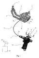
- FIG. 1 1 shows a calibration device 7, an instrument 9, a holder 10, a detection device 20 and a data processing device 30.
- the calibration device 7 comprises a marker device which has marker spheres 1, 2 and 3.
- the marker spheres 1, 2 and 3 are connected to each other via the body of the calibrating device 7 and occupy mutually predetermined relative positions.
- the body of the calibrator 7 preferably comprises openings. Of these openings, only the openings 8, 8a, 8b and 8c are provided with reference numerals for reasons of clarity.
- the openings are preferably cylindrical depressions having a known depth and a known diameter. Preferably, the openings differ in terms of their diameter.
- a code denoting the diameter of the opening is preferably printed adjacent to the opening.
- the instrument 9 is preferably elongated and flexible, in particular elastic.
- the instrument preferably has a circular cross-section. In the in FIG. 1 As shown, the instrument is strongly curved. In practical application, however, the instruments can be made considerably more rigid and allow only a slight curvature.
- the instruments are particularly made of stainless steel, as it is used in particular in medicine and surgery.
- the modulus of elasticity of steel is 190 GPa to 200 GPa.
- glass fiber is 50 GPa to 90 GPa, whereas against that of silicone rubber, for example, only 10 MPa to 100 MPa.
- the instrument may also have other diameters, such as rectangular diameters, for example in the case of a metal plate.
- Typical diameters are in the millimeter range of z. B. greater than 0.1 mm and / or less than 20 mm.
- instruments are ultrasound probes, cannulas, catheters, in particular for ventricular drainage and for use in pain therapy (for example, peridural anesthesia, in particular PDK) or needles, as used, for example, in vertibroplasty or facet infiltration.
- pain therapy for example, peridural anesthesia, in particular PDK
- needles as used, for example, in vertibroplasty or facet infiltration.
- the instrument 9 is fastened to the holder 10 at a mounting end 11 of the holder 10.
- the instrument 9 is inserted into a suitably formed sleeve which is provided at the mounting end 11, and for example, due to the accuracy of fit and / or by means of a screw with the holder 10 fixedly connected.
- a marker device 12 which has three marker balls 4, 5 and 6.
- the marker balls 4, 5 and 6 of the marker device 12 are connected to each other via arms so that they occupy a predetermined relative position to each other.
- Calibrator 7 and holder 10 are calibrated so that the relative locations of at least portions of the surface of holder 10 and calibrator 7 relative to the marker spheres are known.
- the relative position between the openings (8, 8a, 8b, 8c,...) Of the calibrating device 7 relative to the marker spheres 1, 2 and 3 is known.
- the relative position of the mounting end 11 relative to the marker means 12 is known.
- the data and information referred to above as known are stored in the data processing device 30.
- the relative positions of the marker spheres 1, 2 and 3 relative to the apertures and the relative positions of the marker spheres 4, 5 and 6 relative to the end 11 are stored in the data processing device 30.
- 30 data signals from the detector device 20 enter the data processing system.
- the detector device 20 detects signals from the marker spheres 1, 2, 3, 4, 5 and 6.
- the detection device 20 is designed as a camera which detects light, for example infrared light, emanating from the marker spheres, in particular reflected by them.
- the marker spheres reflect light if they have passive marker spheres are. In this case, they can be illuminated by continuous or pulsed light sources, for example, so that they reflect the light.
- the instruments used for the invention are preferably thin, d. H. the length is a multiple of the diameter, for example more than 2 times or 5 times or 10 times or 20 times the diameter.
- the geometry of the holder is stored in the computer 30, i. H. the relative position between the marker device 12 and the mounting end 11 is known.
- the mounting end 11 may be plugged into one of the openings 8, 8a, 8b or 8c in the calibrator, for example, until it comes in contact with the bottom of the holes. Since the depth and position (in particular geometry) of the holes is known and the relative position to the marker spheres 1, 2 and 3 is known, the relative position of the marker spheres 4, from the signals detected by the detection device 20 and further processed by the data processing device 30, 5 and 6, which are also detected, relative to the mounting end 11 are calculated by the data processing device 30.
- the instrument 9 is inserted into a preferably precisely fitting opening 8, so that the inner diameter of the opening 8 (at least approximately) coincides with the outer diameter of the instrument 9.
- the diameter of the opening 8 may be read by the calibrator by an operator and entered into the data processing device 30 for further processing.
- the determination of the diameter of the instrument 9 may also be automatic (without manual input by a user).
- the distance is significantly greater than the deflection with which the first end 9a of the instrument 9 can deviate from a position which occupies the first end 9a when the instrument 9 is rectilinear.
- the aforementioned openings may have a distance of, for example, 2 cm. If this is the case, the appropriate opening can be derived from the relative position between the marker device 12 and the calibration device 7.
- the data processing device 30 may determine from this relative position that only one of the openings is eligible for insertion of the instrument 9 therein has been.
- the other openings would require a significantly greater deflection of the instrument 9, but which is considered not real. How a practically possible deflection of the instrument 9 is calculated will be explained below.
- the data processing device preferably also processes information about the elasticity of the material of the instrument in addition to the information about the diameter of the instrument.
- the modulus of elasticity is used for this purpose.
- the modulus of elasticity is a material characteristic value from materials engineering, which describes the relationship between stress and strain in the deformation of a solid body with linear elastic behavior. The amount of elastic modulus is greater, the more resistance a material opposes to its deformation.
- the position of the first end 9a of the instrument is known, because this end 9a is inserted all the way into the matching opening 8.
- the position of the bottom of the opening 8 relative to the marker balls 1, 2 and 3 is also known and stored in the data processing device 30.
- the position of the first end 9a of the instrument 9 is known and can be further processed by the data processing device.
- the instrument 9 is also inserted all the way into the sleeve 11 (mounting end 11) of the holder 10.
- the relative position of the second end 9b relative to the marker device 12 is known.
- the position of the second end 9b is thus known.
- the following data is present in the data processing device 30 for further processing: the diameter of the instrument 9, the position of the ends 9a and 9b (for example relative to the detection device 20 in a frame of reference by which the detection device 20 rests) and the modulus of elasticity of the material of the instrument.
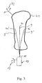
- the angle ⁇ is in FIG. 2 explained.
- the origin of the x, y coordinate system coincides with the bottom in the aperture 8 in the calibrator 7, with the first end of the instrument resting against the bottom.
- EI is the flexural rigidity of the instrument, where E is the modulus of elasticity and I depends on the geometry of the instrument and may be referred to as the cross-sectional moment of inertia.
- E the modulus of elasticity
- I depends on the geometry of the instrument and may be referred to as the cross-sectional moment of inertia.
- I the modulus of elasticity
- I the modulus of elasticity
- I the cross-sectional moment of inertia.
- I which differs from that mentioned above in the equation (1) results.
- the size "1" denotes the length from the first end 9a to a point P. The position of the point P can thus be described by the length 1 and by the angle ⁇ .
- the force acting on the end 9b at the point P e is the force F, which can be decomposed into two components F x (ie the component acting in the x-direction) and Fy (that is to say the component acting in y). It is assumed that the direction of the force F coincides with the tangent T described above. This is a realistic assumption, since with the help of the holder 10, the instrument 9 is to be introduced in practice, for example in a body structure, wherein on the instrument 9 in the direction of the tangent T with the holder 10 a compressive force is exerted to the instrument 9 on to advance in the body structure. It is therefore assumed that no bending forces and torques are exerted on the instrument 9, which can lead to a buckling of the instrument 9 at the assembly end 11 (ie at P e ).
- a force sensor is provided in the holding device 10.
- the force sensor is in particular in the vicinity of the mounting end 11.
- the force sensor preferably measures the amount of force that acts between the instrument 9 and the holder 10.
- the force gauge measures in particular the amount of force and preferably also the direction of the force. If the force sensor is provided, then the force F x and F y can be determined. Thus, from the above equations (2a) and (2b), ⁇ x and ⁇ y can be calculated. This simplifies the determination of the length L by means of equations (4) to (7).
- the instrument 9 for example a Kirschner wire, is inserted into a body structure (eg bone).
- a typical force F is exerted in the longitudinal direction of the instrument 9.
- typical forces used herein in the above calculation are greater than 0.1 N or 1 N or 10 N and, for example, less than 100 N or 1000 N.
- a typical force may be 1 N, for example.
- This assumed force has the magnitude F and is decomposed into the forces F x and F y for the above-mentioned calculation, where F x and F y are a function of F and ⁇ . Equation (4) thus allows the calculation of ⁇ e .
- equations (5) and (6) can then be used to calculate the position P e and thus the relative position between the first end and the second end of the instrument. Since the position of the second end of the instrument can be determined by detection of the marker device 12, the position of the first end of the instrument can be calculated by the data processing device 30 from this.
- the length of the instrument 9 is known and was, for example, with the aid of in FIG. 1 determined arrangement determined.
- the possible position of the first end 9a of the instrument can be calculated.
- the possible locations are in FIG. 3 9a, 9a 'and 9a ".
- the lines 9' and 9" denote the possible course of the instrument within the body structure 40 FIG. 3
- the data processing device 30 is connected to a display
- the z. B. shows the calibrated and registered body structure 40, which is connected for example with a marker device 42, and / or a cone with possible positions of the first end 9a, 9a 'and 9a''and / or possible progressions of the instrument according to the lines 9, 9' and 9 '' from the first end to the second end of the instrument or a portion of the possible courses.
- the surgeon is thus allowed, without the use of an X-ray machine, to assess the risk of getting into an undesired area with the end 9a.
Abstract
Description
Die vorliegend Erfindung betrifft die Längenbestimmung eines Instruments, insbesondere eines medizinischen Instruments, insbesondere bei einer klinischen Anwendung, wie zum Beispiel einer Operation. Bei Markernavigationssystemen, insbesondere bei bildgeführter Chirurgie ("image guided surgery"; IGS) ist es wünschenswert, Instrumente zu registrieren und zu kalibrieren. Es sollte also die relative Lage von Teilen des Instruments relativ zu einem Bezugssystem, das beispielsweise im Raum ruht oder das mit einer Detektionseinrichtung (Kamera) verbunden ist, bekannt sein.The present invention relates to the length determination of an instrument, in particular a medical instrument, in particular in a clinical application, such as surgery. It is desirable to register instruments and spanned at marker navigation systems, particularly in image-guided surgery (IGS "image guided surgery"). Thus, it should be the relative position of parts of the instrument relative to a reference system, which rests for example in space or which is connected to a detection device (camera), be known.
Bei manchen Instrumenten ist es nicht möglich oder nicht gewünscht, an der Spitze des Instruments eine Markereinrichtung anzubringen, da beispielsweise die Spitze des Instruments, beispielsweise ein Nagel sonst für die beabsichtigten Zwecke nicht verwendet werden kann. Dennoch ist es in diesem Fall wünschenswert, dass das Markernavigationssystem Informationen über die Lage der Spitze des Instruments liefert. Hierzu ist eine Information über die Länge des Instruments von Nöten. Die Länge des Instruments kann bei starren Instrumenten beispielsweise einfach durch Abgreifen der beiden Enden mittels eines Pointers bestimmt werden. Der Abstand zwischen den Enden entspricht dann der Länge des Instruments. Dies ist jedoch bei nichtideal starren Instrumenten nur ungenau, wobei die Ungenauigkeit mit zunehmender Elastizität des Instruments zunimmt.In some instruments, it is not possible or undesirable to apply marker means to the tip of the instrument since, for example, the tip of the instrument, such as a nail, can not otherwise be used for its intended purpose. However, in this case it is desirable for the marker navigation system to provide information about the location of the tip of the instrument. This requires information about the length of the instrument. The length of the instrument can be determined with rigid instruments, for example, simply by tapping the two ends by means of a pointer. The distance between the ends then corresponds to the length of the instrument. However, this is only inaccurate in non-ideal rigid instruments, with inaccuracy increasing with increasing elasticity of the instrument.
Aufgabe der Erfindung ist es die Länge flexibler Instrumente vermessen zu können.The object of the invention is to be able to measure the length of flexible instruments.
Vorstehende Aufgabe wird durch die unabhängigen Ansprüche gelöst. Die abhängigen Ansprüche sind auf vorteilhafte Weiterbildungen gerichtet.The above object is solved by the independent claims. The dependent claims are directed to advantageous developments.
Weitere Aufgabe der Erfindung ist es mögliche Positionen des freien Endes des Instruments oder eines Instrumentsabschnittes durch das Markernavigationssystem anzuzeigen, wenn das andere Ende festgehalten wird.Another object of the invention is to indicate possible positions of the free end of the instrument or an instrument section by the marker navigation system when the other end is retained.
Erfindungsgemäß werden mittels einer Detektionseinrichtung (z. B. Kamera oder Ultraschalldetektor) Markereinrichtungen detektiert. Die Markereinrichtungen umfassen typischerweise drei Marker, die in fester und vorbestimmter relativer Lage zueinander angeordnet sind und insbesondere mechanisch verbunden sind. Die Marker können passive oder aktive Marker sein, wobei die passiven Marker Signale (z.B. Wellen und/oder Strahlung) reflektieren, die in ihre Richtung ausgesendet werden und die aktiven Marker selbst Ursprung der Signale (z.B. Strahlung und/oder Wellen) sind. Die von den (aktiven oder passiven) Markern ausgehenden Signale, bei denen es sich z.B. um Wellensignale oder Strahlungssignale handeln kann, werden von einer Detektionsvorrichtung (z. B. Kamera) detektiert. Um eine Position der Markereinrichtung relativ zu der Detektionseinrichtung festzulegen, wird dabei vorzugsweise die Markereinrichtung bewegt, um der Detektionseinrichtung verschiedene Ansichten der Markereinrichtung zu bieten. Auf dieser Grundlage kann dann in bekannter Weise die relative Lage der Markereinrichtung relativ zu der Detektionseinrichtung, insbesondere in einem im Raum ruhenden Bezugssystem bestimmt werden. In diesem Zusammenhang wird auf die
Die Lage der Markereinrichtung wird bevorzugt durch die Position der Markereinrichtung in einem vorbestimmen Bezugssystem bestimmt. Vorzugsweise wird als Bezugssystem ein Bezugssystem verwendet, in dem die Detektionseinrichtung ruht. Insbesondere wird die Lage der Markereinrichtung durch die Positionen der Marker, insbesondere der Mittelpunkte der Marker in einem Bezugssystem bestimmt. Die Positionen können zum Beispiel mit kartesischen Koordinaten oder Kugelkoordinaten beschrieben werden. Die relative Lage von einem Teil (z. B. Detektionseinrichtung oder Markereinrichtung) zu einem anderen Teil (z. B. Markereinrichtung) kann insbesondere durch Raumwinkel und/oder Abstände und/oder Koordinaten (in einem Bezugssystem) und/oder Vektoren beschrieben werden und wird vorzugsweise aus dem die Lage beschreibenden Positionen z. B. mittels eines Programms errechnet, das auf einem Computer läuft.The position of the marker device is preferably determined by the position of the marker device in a predetermined reference frame. Preferably, a reference system in which the detection device rests is used as the reference system. In particular, the position of the marker device is determined by the positions of the markers, in particular the midpoints of the markers in a reference frame. The positions can be described, for example, with Cartesian coordinates or spherical coordinates. The relative position of one part (eg detection device or marker device) to another part (eg marker device) can be described in particular by solid angles and / or distances and / or coordinates (in a frame of reference) and / or vectors and is preferably from the position describing the position z. B. calculated by means of a program that runs on a computer.
Der hierin verwendete Begriff "relative Lage" oder der Ausdruck "Lage eines Teils A relativ zu einem Teil B" umfasst also den Begriff der relativen Positionen zwischen den zwei Teilen, insbesondere zwischen den Markereinrichtungen und/oder deren Markern oder zwischen einer Markereinrichtung (oder deren Markern) und der Detektionseinrichtung. Insbesondere werden Schwerpunkte oder Mittelpunkte der Teile als punktförmiger Bezugspunkt zum Festlegen einer Position gewählt. Ist die Position eines Teils in einem Bezugssystem bekannt, so kann basierend auf der relativen Lage zweier Teile aus der Position eines der zwei Teile die Position des anderen der zwei Teile berechnet werden.The term "relative position" as used herein or the term " position of a part A relative to a part B" thus includes the term relative positions between the two parts, in particular between the marker devices and / or their markers or between a marker device (or its Markers) and the detection device. In particular, centroids or center points of the parts are selected as a point reference point for determining a position. If the position of a part in a reference frame is known, the position of the other of the two parts can be calculated based on the relative position of two parts from the position of one of the two parts.
Insbesondere falls die Markereinrichtung nur zwei Marker umfasst, ist bevorzugt eine Startposition bekannt und die Markersystem erlaubt dann die Verfolgung der Lage der Markereinrichtung bei Bewegung der Markereinrichtung im Raum.In particular, if the marker device comprises only two markers, a start position is preferably known and the marker system then allows tracking of the position of the marker device when the marker device moves in space.
Die Markereinrichtung gemäß der vorliegenden Erfindung umfasst also vorzugsweise mindestens zwei Marker, insbesondere und bevorzugt drei Marker und können natürlich auch mehr als drei Marker umfassen. Die Abmessungen der Marker und die relativen Lagen der Marker zueinander sind bekannt und liegen insbesondere als vorbekannte Daten einer Datenverarbeitungseinrichtung vor. Vorzugsweise ist auch die Form der Marker bekannt.The marker device according to the present invention therefore preferably comprises at least two markers, in particular and preferably three markers, and may of course also comprise more than three markers. The dimensions of the markers and the relative positions of the markers to each other are known and exist in particular as previously known data of a data processing device. Preferably, the shape of the marker is known.
Weiter umfasst das erfindungsgemäße Markernavigationssystem vorzugsweise eine Detektionseinrichtung, die Signale von den mindestens zwei Markern detektiert. Wie zuvor ausgeführt handelt es sich hierbei um von den Markern ausgehende Signale, die entweder aktiv von den Markern ausgesendet werden oder von den Markern reflektiert werden. Im letzteren Fall ist vorzugsweise weiter eine Signalsendequelle beispielsweise eine Infrarotlichtquelle vorgesehen, die Signale (z. B. Ultraschallwellen oder Infrarotlicht) in Richtung auf die passiven Marker (kontinuierlich oder gepulst) aussendet, wobei die passiven Marker die Signale reflektieren. Eine Datenverarbeitungseinrichtung, insbesondere ein Computer erlaubt die Berechnung der relativen Lage der Markereinrichtung relativ zur Detektionseinrichtung, insbesondere die Berechnung der Lage der Markereinrichtung in einem Bezugssystem, indem die Detektionseinrichtung ruht, also beispielsweise in einem Bezugssystem, das in einem Operationssaal ruht.Furthermore, the marker navigation system according to the invention preferably comprises a detection device which detects signals from the at least two markers. As previously stated, these are signals emanating from the markers, which are either actively transmitted by the markers or reflected by the markers. In the latter case, a signal transmission source, for example an infrared light source, is preferably provided which emits signals (eg ultrasonic waves or infrared light) in the direction of the passive markers (continuous or pulsed), the passive markers reflecting the signals. A data processing device, in particular a computer, allows the calculation of the relative position of the marker device relative to the detection device, in particular the calculation of the position of the marker device in a reference system, by the detection device resting, for example in a reference system resting in an operating room.
Die erfindungsgemäße Datenverarbeitungseinrichtung ist vorzugsweise ausgebildet, um Berechnungs- und Bestimmungsoperationen durchzuführen. Erfindungsgemäß werden durch die Datenverarbeitungseinrichtung die Lagen der Markereinrichtungen basierend auf den detektierten Signalen, die von den Markereinrichtungen ausgehen, berechnet. Vorzugsweise sind die Gegenstände (Körperstruktur oder Instrument), an denen die Markereinrichtungen angebracht sind, kalibriert. Dies bedeutet, dass die relativen Lagen zumindest zwischen Teilen des Gegenstandes und der Markereinrichtung, die an dem Gegenstand angebracht ist, bekannt sind und/oder insbesondere in der Datenverarbeitungseinrichtung abgespeichert sind, so dass insbesondere Anzeigesignale, die die Lagen der Gegenstände beschreiben, basierend auf den Lagen der Markereinrichtungen bestimmt werden können. Die Lagen der Markereinrichtungen werden bevorzugt relativ zu der Detektionseinrichtung berechnet, also in einem Bezugssystem, in dem die Detektionseinrichtung ruht. Natürlich können die Lagen auch in einem anderen Bezugssystem berechnet werden, z.B. in einem Bezugssystem, in dem der Patient ruht und/oder in dem eine der Markereinrichtungen ruht.The data processing device according to the invention is preferably designed to perform calculation and determination operations. According to the invention, the positions of the marker devices are calculated by the data processing device on the basis of the detected signals emanating from the marker devices. Preferably, the objects (body structure or instrument) to which the marker devices are attached are calibrated. This means that the relative positions are known at least between parts of the object and the marker device which is attached to the object and / or are stored in particular in the data processing device, so that in particular display signals describing the positions of the objects based on the Layers of the marker devices can be determined. The layers of Marker devices are preferably calculated relative to the detection device, that is to say in a reference system in which the detection device rests. Of course, the layers can also be calculated in another frame of reference, eg in a frame of reference in which the patient is resting and / or in which one of the marker devices rests.
Das erfindungsgemäße Markernavigationssystem erlaubt insbesondere die Längenbestimmung, vorzugsweise aber auch die Bestimmung des Durchmessers, insbesondere auch der Form des Instruments sowie vorzugsweise auch die möglichen Lagen des Instruments.The marker navigation system according to the invention allows in particular the length determination, but preferably also the determination of the diameter, in particular also the shape of the instrument and preferably also the possible positions of the instrument.
Das Markernavigationssystem umfasst einen Halter, der ausgebildet ist, um das Instrument zu halten. Insbesondere wird ein Ende des Instruments (das zweite Ende) an dem Halter (mechanisch), insbesondere lösbar angebracht. Das Instrument ist vorzugsweise so an dem Halter angebracht, dass die relative Lage zwischen dem zweiten Ende des Instruments und dem Halter fixiert ist, d. h. das zweite Ende des Instruments ist relativ zu dem Halter ortsfest. Wie oben ausgeführt, ist dies für das andere Ende, das erste Ende des Instruments nicht gewährleistet, da das Instrument zumindest in einem gewissen Umfang flexibel ist. Bei einem ideal starren Instrument wäre auch das erste Ende des Instruments ortsfest zu dem Halter. Der Halter umfasst vorzugsweise einen Griff und kann zum Beispiel auch eine Maschine, wie beispielsweise ein Bohrgerät umfassen, das ausgebildet ist, das fixierte Instrument zu drehen.The marker navigation system includes a holder configured to hold the instrument. In particular, one end of the instrument (the second end) is attached to the holder (mechanically), in particular detachably. The instrument is preferably mounted on the holder such that the relative position between the second end of the instrument and the holder is fixed, i. H. the second end of the instrument is fixed relative to the holder. As stated above, this is not guaranteed for the other end, the first end of the instrument, since the instrument is flexible at least to some extent. In an ideally rigid instrument and the first end of the instrument would be fixed to the holder. The holder preferably includes a handle and may, for example, also include a machine, such as a drill, configured to rotate the fixed instrument.
Weiter ist vorzugsweise ein Kalibriergerät vorgesehen, das die Bestimmung des Durchmessers und/oder der Querschnittsform des Instruments erlaubt. Hierzu ist in dem Kalibriergerät vorzugsweise mindestens eine Öffnung vorgesehen. Sind mehrere Öffnungen vorgesehen, so haben diese vorzugsweise eine unterschiedliche Form, sodass unterschiedlich gestaltete Instrumente eingeführt werden können. Vorzugsweise werden Instrumente vermessen, deren Querschnittsform über die gesamte Länge des Instruments konstant ist, denn vorzugsweise fließt in die Berechnung der Länge des Instruments und /oder der möglichen Lagen des ersten Endes des Instruments Information über die Form des Instruments ein, also beispielsweise die Annahme ein, das der Querschnitt des Instruments über die gesamte Länge gleich ist.Furthermore, a calibration device is preferably provided which allows the determination of the diameter and / or the cross-sectional shape of the instrument. For this purpose, at least one opening is preferably provided in the calibration device. If several openings are provided, they preferably have a different shape, so that differently shaped instruments can be introduced. Preferably, instruments are measured whose cross-sectional shape over the entire length of the instrument is constant, because preferably flows into the calculation of the length of the instrument and / or the possible positions of the first end of the instrument information about the shape of the instrument, so for example the assumption in that the cross-section of the instrument is the same over the entire length.
Sind in dem Kalibriergerät mehrere Öffnungen vorgesehen, so haben diese vorzugsweise eine unterschiedliche Form und Größe. Auf dieser Art und Weise kann durch passgenaues Einführen eines Instruments in die Öffnungen eine der Öffnungen dem Instrument zugeordnet werden. Da die Form und Größe der Öffnung bekannt ist, entspricht Form und Größe des Querschnitts des Instruments demjenigen der Öffnung. Da weiterhin die relative Lage der Öffnung relativ zu der zweiten Markereinrichtung bekannt ist, die an dem Kalibriergerät angebracht ist, ist weiterhin bekannt, wo sich das erste Ende des Instruments befindet wenn es passgenau, und insbesondere bis zum Anschlag in die Öffnung eingeführt wurde. Da insbesondere auch die relative Lage des Bodens einer jeden Öffnung relativ zu der zweiten Markereinrichtung bekannt ist, ist somit auch die Lage des ersten Endes des Instruments bekannt.If several openings are provided in the calibration device, they preferably have a different shape and size. This way can be done by custom fit Inserting an instrument into the openings one of the openings are assigned to the instrument. Since the shape and size of the opening is known, the shape and size of the cross section of the instrument corresponds to that of the opening. Further, since the relative position of the opening relative to the second marker device is known, which is attached to the calibrator, it is also known where the first end of the instrument is when it has been precisely inserted, and in particular into the opening until it stops. In particular, since the relative position of the bottom of each opening is known relative to the second marker means, so is the position of the first end of the instrument known.
Im Falle eines Instruments mit kreisförmigem Querschnitt, ist die mindestens eine Öffnung ebenfalls eine Öffnung mit einem kreisrunden Querschnitt, also eine zylindrische Bohrung. Natürlich können auch Öffnungen anderer Formen z. B. rechteckige Formen vorgesehen sein, um Instrumente mit rechteckigem Querschnitt passgenau einführen und damit vermessen zu können.In the case of an instrument with a circular cross-section, the at least one opening is also an opening with a circular cross-section, ie a cylindrical bore. Of course, openings of other forms z. B. rectangular shapes may be provided to introduce instruments with rectangular cross-section fit and thus be able to measure.
Die oben genannte Detektionseinrichtung ist ausgebildet, um eine erste Lage der ersten Markereinrichtung, die der Halter aufweist und eine zweite Lage der zweiten Markereinrichtung, die das Kalibriergerät aufweist, zu detektieren.The above-mentioned detection device is designed to detect a first layer of the first marker device that has the holder and a second layer of the second marker device that has the calibration device.
Die oben genannte Datenverarbeitungseinrichtung erlaubt unter der Verwendung bestimmter Informationen, die von der Detektionseinrichtung stammen und/oder vorgegeben sind und/oder eingegeben werden, die Länge des Instruments zu bestimmen, insbesondere zu berechnen.The above-mentioned data processing device allows using the particular information that originate from the detection device and / or are predetermined and / or input, to determine the length of the instrument, in particular to calculate.
Bei diesen Informationen handelt es sich insbesondere um die Folgenden. Die oben genannte erste und zweite Lage wurde von der Detektionseinrichtung bestimmt und die Daten hierzu werden in die Datenverarbeitungseinrichtung eingegeben. Die Information über den Querschnitt des Instruments kann von einem Benutzer eingegeben werden, der eine Kennzahl abliest, die neben der Öffnung geschrieben steht, in die das Instrument eingeführt wurde, und die die Form und/oder Größe und/oder Durchmesser der Öffnung kennzeichnet. Alternativ kann dies natürlich beispielsweise auch durch Bildverarbeitung erfolgen, wobei eine Kamera (beispielsweise dieselbe, die auch als Detektionseinrichtung verwendet wird) den Bereich beobachtet, wo das erste Ende des Instruments in die mindestens eine Öffnung des Kalibriergeräts eingeführt wird. Aus der optischen Auswertung des Kamerabildes (beispielsweise den Markierungen neben den Öffnungen), lässt sich dann mittels der Datenverarbeitungseinrichtung ermitteln, in welche Öffnung das erste Ende des Instruments eingeführt ist. Weitere mögliche Arten der Bestimmung der Öffnung, in die das Instrument eingeführt wurde, werden bei der detaillierten Beschreibung weiter unten offenbart. Ist somit die Information über den Querschnitt (beispielsweise der Durchmesser und/oder die Querschnittsfläche und/oder die Form des Querschnitts) des Instruments bekannt, so ist eine wesentliche Information über das Instrument gegeben. Die andere wesentliche Information über das Instrument, nämlich die Länge, wird vorzugsweise zusätzlich auf den folgenden Informationen bestimmt. Die Information über die Elastizität des Materials des Instruments. Die Elastizität des Materials des Instruments lässt sich beispielsweise durch den Elastizitätsmodul beschreiben, der auch Youngscher Modul genannt wird. Weiter wird zur Bestimmung der Länge vorzugsweise die relative Lage zwischen dem zweiten Ende des Instruments und der ersten Markereinrichtung verwendet. Hierbei kann man nutzen, dass das zweiten Ende des Instruments an einer Anschlagsfläche des Halters anliegend am Halter angebracht wird. Die relative Lage zwischen Anschlagsfläche des Halters und der ersten Markereinrichtung (des Halters) ist vorzugsweise bekannt und in der Datenverarbeitungseinrichtung gespeichert. Soweit hierin von "bekannten Daten" oder "bekannten Informationen" oder ähnlichen gesprochen wird, sind dies vorzugsweise Daten, die in der Datenverarbeitungseinrichtung gespeichert sind. Entsprechendes gilt für die relative Lage zwischen der zweiten Markereinrichtung (des Kalibriergerätes) und der mindestens einen Öffnung. Dabei ist, wie oben bereits ausgeführt wurde, insbesondere die relative Lage zwischen dem Boden der mindestens einen Öffnung, an dem vorzugsweise das erste Ende des Instruments anliegt und der zweiten Markereinrichtung bekannt.This information is specifically the following. The above-mentioned first and second positions have been determined by the detection device and the data therefor are input to the data processing device. The information about the cross-section of the instrument may be entered by a user reading a code written next to the aperture into which the instrument has been inserted and identifying the shape and / or size and / or diameter of the aperture. Alternatively, this can of course also be done, for example, by image processing, wherein a camera (for example, the same, which is also used as a detection device) observes the area where the first end of the instrument in the at least one opening of the Calibrator is introduced. From the optical evaluation of the camera image (for example the markings next to the openings), the data processing device can then be used to determine into which opening the first end of the instrument is inserted. Other possible ways of determining the opening into which the instrument was introduced are disclosed in the detailed description below. If the information about the cross-section (for example the diameter and / or the cross-sectional area and / or the shape of the cross-section) of the instrument is thus known, essential information about the instrument is given. The other essential information about the instrument, namely the length, is preferably additionally determined on the following information. The information about the elasticity of the material of the instrument. The elasticity of the material of the instrument can be described for example by the modulus of elasticity, which is also called Young's modulus. Furthermore, the relative position between the second end of the instrument and the first marker device is preferably used to determine the length. In this case, it can be used that the second end of the instrument is attached to a stop surface of the holder adjacent to the holder. The relative position between the abutment surface of the holder and the first marker device (the holder) is preferably known and stored in the data processing device. As used herein to refer to " known data" or " known information" or the like, these are preferably data stored in the data processing device. The same applies to the relative position between the second marker device (of the calibration device) and the at least one opening. In this case, as has already been explained above, in particular the relative position between the bottom of the at least one opening, against which preferably the first end of the instrument rests, and the second marker device are known.
Zusätzlich zu den oben genannten Informationen ist vorzugsweise auch noch eine Kraft bekannt, die auf das Instrument wirkt. In diesem Fall wird vorzugsweise davon ausgegangen, dass das Instrument, für den Fall, dass keine Kraft wirkt, geradlinig ist und im Falle einer Krafteinwirkung das Instrument sich krummlinig erstreckt, also durch die Krafteinwirkung gebogen wird.In addition to the above-mentioned information, a force which acts on the instrument is preferably also known. In this case, it is preferably assumed that the instrument, in the event that no force acts, is rectilinear and in the case of a force, the instrument extends curvilinear, that is bent by the action of force.
Bei der Berechnung wird vorzugsweise von einer stetigen Krümmung ausgegangen, es sollen also keine Knicke im Längsverlauf des Instruments entstehen. Alternativ oder zusätzlich wird davon ausgegangen, dass die Kraft, die auf das Instrument wirkt, nur an den Enden des Instruments wirkt, vorzugsweise nur an einem Ende. Dabei wird bei der Berechnung mittels der Datenverarbeitungseinrichtung vorzugsweise weiter davon ausgegangen, dass die Kraft an dem Ende, an dem sie angreift in die Richtung wirkt, in die sich das Instrument an diesem Ende erstreckt. Die Richtung der Kraft stimmt also mit der Richtung einer Tangente überein, die an dem Ende des Instruments an das gekrümmte Instrument angelegt wird. Insbesondere wirkt eine Kraft zwischen einer Stirnseite des Instruments am zweiten Ende des Instruments und dem Halter. Es wird also davon ausgegangen, dass mit dem Halter auf die Stirnseite des Instruments eine Kraft ausgeübt wird, die zu einer Krümmung des Instruments führt.The calculation is preferably based on a continuous curvature, so there should be no kinks in the longitudinal course of the instrument. Alternatively or additionally, it is assumed that the force acting on the instrument only at the ends of the Instruments acts, preferably only at one end. In this case, in the calculation by means of the data processing device, it is further preferably assumed that the force acts on the end at which it acts in the direction in which the instrument extends at this end. The direction of the force thus coincides with the direction of a tangent which is applied to the curved instrument at the end of the instrument. In particular, a force acts between an end face of the instrument at the second end of the instrument and the holder. It is therefore assumed that with the holder on the front side of the instrument a force is exerted, which leads to a curvature of the instrument.
Vorzugsweise wird zur Längenbestimmung des Instruments der Halter bewegt, um eine Vielzahl erster und/oder zweiter Lagen zu detektieren und in die Berechnung einfließen zu lassen. Auf diese Art und Weise lässt sich die Genauigkeit der Bestimmung der Länge des Instruments erhöhen, indem beispielsweise die für die verschiedenen ersten und/oder zweiten Lagen bestimmten Längen einer Mittelwertbildung unterzogen werden. Alternativ oder zusätzlich lässt sich aus den detektierten, verschiedenen ersten und zweiten Lagen eine mögliche Auslenkbarkeit des Instruments bei seiner Anwendung bestimmen und vorzugsweise von der Datenverarbeitungseinrichtung abspeichern. Es lässt sich also feststellen, welche möglichen relativen Lagen das erste Ende relativ zum zweiten Ende einnehmen kann. Vorteilhaft ist hierbei, wenn derselbe Benutzer das Verfahren zur Längenbestimmung ausführt, der später das Instrument einsetzt, denn es ist davon auszugehen, dass der Benutzer ähnliche Kräfte aufwendet. Die somit festgestellten möglichen relativen Lagen zwischen dem ersten Ende und dem zweiten Ende können dann bei der (medizinischen) Anwendung des an dem Halter angebrachten Instruments als mögliche Lagen angezeigt werden. Alternativ können diese möglichen Lagen des Instruments, insbesondere des ersten Endes auch berechnet werden, wie im Folgenden ausgeführt wird.Preferably, the holder is moved to determine the length of the instrument in order to detect a multiplicity of first and / or second layers and to incorporate them into the calculation. In this way, the accuracy of determining the length of the instrument can be increased by, for example, averaging the lengths determined for the various first and / or second layers. Alternatively or additionally, from the detected, different first and second layers, a possible deflectability of the instrument can be determined during its application and preferably stored by the data processing device. It is therefore possible to determine which possible relative positions the first end can occupy relative to the second end. In this case, it is advantageous if the same user executes the method for length determination, which later uses the instrument, because it can be assumed that the user spends similar forces. The thus determined possible relative positions between the first end and the second end can then be displayed as possible positions in the (medical) application of the instrument attached to the holder. Alternatively, these possible positions of the instrument, in particular the first end, can also be calculated, as will be explained below.
Erfindungsgemäß ist es nach einer erfolgreichen Längenbestimmung und ohne weitere Verwendung des Kalibriergeräts möglich, den Verlauf des Instruments bei gegebener Kraft (mit gegebenem Betrag der Kraft und gegebener Richtung der Kraft) zu berechnen und insbesondere die Lage des ersten Endes des Instruments zu bestimmen, wenn lediglich die Lage des zweiten Endes des Instruments bestimmbar ist. Wie oben ausgeführt wurde, ist die Lage des zweiten Endes des Instruments beispielsweise durch die Detektion der ersten Markereinrichtung, die an dem Halter angebracht ist, und durch die bekannte relative Lage zwischen der ersten Markereinrichtung und dem zweiten Ende des Instruments bestimmbar.According to the invention, after successful length determination and without further use of the calibrator, it is possible to calculate the course of the instrument for a given force (given amount of force and given direction of force) and, in particular, to determine the position of the first end of the instrument, if only the position of the second end of the instrument can be determined. As stated above, the position of the second end of the instrument is determinable, for example, by the detection of the first marker means mounted on the holder and the known relative position between the first marker means and the second end of the instrument.
Die bekannte Gestalt (Querschnitt und Länge) des Instruments in Verbindung mit der bekannten Elastizität des Materials des Instruments erlaubt dann die Berechnung der Krümmung und insbesondere der Lage des ersten Endes des Instruments und/oder die Berechnung des Verlaufs des Instruments vom ersten zum zweiten Ende. Diese berechneten Informationen können zumindest teilweise durch eine Anzeige angezeigt werden. Ist insbesondere ein Teil des Instruments, der das erste Ende umfasst, für den Bediener (Operateur) nicht sichtbar, so erlaubt die Berechnung des möglichen Verlaufs des Instruments die Berechnung eines Bereichs, in dem sich der nicht sichtbare Teil des Instruments bei bekannter oder gemessener Kraft befinden kann. Beispielsweise kann das Instrument, wenn es in eine Körperstruktur eingeführt wird, allmählich von einer geradlinigen Erstreckung abweichen und in eine krummlinige Erstreckung übergehen. Dies kann dazu führen, dass sich das erste Ende in einem nicht gewünschten Bereich der Körperstruktur befinden kann. Durch die Anzeige des möglichen Aufenthaltsbereichs des Instruments kann der Operateur entscheiden, ob ein derartiges Risiko besteht oder nicht und beispielsweise zusätzliche Untersuchungsmaßnahmen (Röntgenbilder) dies überprüfen.The known shape (cross section and length) of the instrument in conjunction with the known elasticity of the material of the instrument then allows the calculation of the curvature and in particular the position of the first end of the instrument and / or the calculation of the course of the instrument from the first to the second end. This calculated information can be at least partially displayed by an advertisement. In particular, if a part of the instrument comprising the first end is not visible to the operator (operator), the calculation of the possible course of the instrument allows calculation of a region in which the invisible part of the instrument is known or measured can be located. For example, when introduced into a body structure, the instrument may gradually deviate from a rectilinear extent and transition into a curvilinear extent. This can cause the first end to be in an undesirable area of the body structure. By displaying the possible area of residence of the instrument, the surgeon can decide whether such a risk exists or not and, for example, additional examination measures (X-ray images) check this.
Wie oben ausgeführt, kann die Kraft nicht nur als bekannt vorausgesetzt werden, indem ein wahrscheinlicher Wert für die Kraft verwendet wird, sondern es kann die Kraft auch gemessen werden. Hierzu kann in dem Halter ein Kraftsensor (insbesondere in der Nähe des zweiten Endes des Instruments) vorgesehen werden, der Betrag und/oder Richtung der von dem Halter auf das Instrument ausgeübten Kraft misst und an die Datenverarbeitungseinrichtung zur weiteren Verarbeitung weitergibt.As stated above, not only can the force be assumed to be known by using a probable value for the force, but the force can also be measured. For this purpose, a force sensor (in particular in the vicinity of the second end of the instrument) can be provided in the holder, which measures the amount and / or direction of the force exerted by the holder on the instrument and forwards it to the data processing device for further processing.
Im Folgenden erfolgt eine detaillierte Beschreibung der Erfindung. Dabei werden weitere vorteilhafte Merkmale der Erfindung offenbart. Verschiedene Merkmale unterschiedlicher Ausführungsformen können miteinander kombiniert werden.
-
Figur 1 zeigt eine Ausführungsform eines erfindungsgemäßen Markernavigationssystems. -
Figur 2 -
Figur 3
-
FIG. 1 shows an embodiment of a marker navigation system according to the invention. -
FIG. 2 Thematically shows the curvature of an instrument, as a basis for calculating the length. -
FIG. 3 shows possible courses of the instrument within a body structure.
Das Kalibriergerät 7 umfasst eine Markereinrichtung, die Markerkugeln 1, 2 und 3 aufweist. Die Markerkugeln 1, 2 und 3 sind über den Körper des Kalibriergeräts 7 miteinander verbunden und nehmen zueinander vorbestimmte relative Lagen ein. Der Körper des Kalibriergeräts 7 umfasst vorzugsweise Öffnungen. Von diesen Öffnungen sind nur die Öffnungen 8, 8a, 8b und 8c aus Übersichtlichkeitsgründen mit Bezugszeichen versehen. Die Öffnungen sind vorzugsweise zylindrische Vertiefungen mit einer vorbekannten Tiefe und einem vorbekannten Durchmesser. Vorzugsweise unterscheiden sich die Öffnungen hinsichtlich ihres Durchmessers. Eine Kennzahl, die den Durchmesser der Öffnung bezeichnet ist vorzugsweise neben die Öffnung gedruckt.The
Das Instrument 9 ist vorzugsweise länglich und flexibel, insbesondere elastisch. Das Instrument hat vorzugsweise einen kreisrunden Querschnitt. In der in
Das Instrument kann auch andere Durchmesser, wie beispielsweise rechteckförmige Durchmesser, beispielsweise im Falle einer Blechplatte aufweisen.The instrument may also have other diameters, such as rectangular diameters, for example in the case of a metal plate.
Beispiele für Instrumente stellen der Kirschnerdraht, Schrauben, insbesondere Schanzschrauben für Knochen, Bohrer, Marknagel, Steinmannpins (für die externe Fixation des Knochens) dar. Typische Durchmesser liegen im Millimeterbereich von z. B. größer 0,1 mm und/oder kleiner 20 mm.Examples of instruments are the Kirschner wire, screws, especially Schanz screws for bone, drill, intramedullary nail, Steinmann pins (for the external fixation of the bone). Typical diameters are in the millimeter range of z. B. greater than 0.1 mm and / or less than 20 mm.
Andere mögliche Instrumente sind die Schenkel einer Zange oder die Klingen einer Schere, die ebenfalls eine gewisse Elastizität aufweisen.Other possible instruments are the legs of a pair of pliers or the blades of a pair of scissors, which also have some elasticity.
Weitere Beispiele für Instrumente sind Ultraschallsonden, Kanülen, Katheter, insbesondere für die Ventrikeldrainage und zur Verwendung bei der Schmerztherapie (beispielsweise Periduralanästhesie, insbesondere PDK) oder Nadeln, wie sie beispielsweise bei der Vertibroplastie oder Facetteninfiltration verwendet werden.Further examples of instruments are ultrasound probes, cannulas, catheters, in particular for ventricular drainage and for use in pain therapy (for example, peridural anesthesia, in particular PDK) or needles, as used, for example, in vertibroplasty or facet infiltration.
Das Instrument 9 wird an einem Montagende 11 des Halters 10 an dem Halter 10 befestigt. Beispielsweise wird hierzu das Instrument 9 in eine passend ausgebildete Hülse, die an dem Montageende 11 vorgesehen ist, eingeführt und beispielsweise aufgrund der Passgenauigkeit und/oder mittels einer Schraube mit dem Halter 10 ortsfest verbunden.The
Am Halter 10 ist ebenfalls eine Markereinrichtung 12 vorgesehen, die drei Markerkugeln 4, 5 und 6 aufweist. Die Markerkugeln 4, 5 und 6 der Markereinrichtung 12 sind über Arme miteinander so verbunden, dass sie eine vorbestimmte relative Lage jeweils zueinander einnehmen.On the
Das Kalibriergerät 7 und der Halter 10 sind kalibriert, sodass die relativen Lagen zumindest von Teilen der Oberfläche des Halters 10 und des Kalibriergeräts 7 relativ zu den Markerkugeln bekannt sind.
Insbesondere ist die relative Lage zwischen den Öffnungen (8, 8a, 8b, 8c,...) des Kalibriergeräts 7 relativ zu den Markerkugeln 1, 2 und 3 bekannt. Weiter ist die relative Lage des Montageendes 11 relativ zu der Markereinrichtung 12 (relativ zu den Markerkugeln 4, 5 und 6) bekannt.In particular, the relative position between the openings (8, 8a, 8b, 8c,...) Of the
Vorzugsweise sind die oben als bekannt bezeichneten Daten und Informationen in der Datenverarbeitungseinrichtung 30 gespeichert. Insbesondere sind die relativen Lagen der Markerkugeln 1, 2 und 3 relativ zu den Öffnungen und die relativen Lagen der Markerkugeln 4, 5 und 6 relativ zu dem Ende 11 in der Datenverarbeitungseinrichtung 30 gespeichert. Weiter gehen in die Datenverarbeitung 30 Datensignale von der Detektoreinrichtung 20 ein. Die Detektoreinrichtung 20 detektiert Signale von den Markerkugeln 1, 2, 3, 4, 5 und 6. Insbesondere ist die Detektionseinrichtung 20 als Kamera ausgebildet, die Licht, beispielsweise Infrarotlicht detektiert, das von den Markerkugeln ausgeht, insbesondere von diesen reflektiert wird. Die Markerkugeln reflektieren Licht, falls sie passive Markerkugeln sind. In diesem Fall können sie beispielsweise durch kontinuierliche oder gepulste Lichtquellen angestrahlt werden, sodass sie das Licht reflektieren.Preferably, the data and information referred to above as known are stored in the
Die für die Erfindung verwendeten Instrumente sind vorzugsweise dünn, d. h. die Länge beträgt ein Vielfaches des Durchmessers, beispielsweise mehr als das 2-fache oder 5-fache oder 10-fache oder 20-fache des Durchmessers.The instruments used for the invention are preferably thin, d. H. the length is a multiple of the diameter, for example more than 2 times or 5 times or 10 times or 20 times the diameter.
Im oben beschriebenen Fall ist die Geometrie des Halters im Computer 30 gespeichert, d. h. die relative Lage zwischen der Markereinrichtung 12 und dem Montageende 11 ist bekannt. Alternativ kann das Montageende 11 beispielsweise in eine der Öffnungen 8, 8a, 8b oder 8c in das Kalibriergeräts gesteckt werden, bis es mit dem Boden der Löcher in Kontakt kommt. Da die Tiefe und Lage (insbesondere Geometrie) der Löcher bekannt ist und die relative Lage zu den Markerkugeln 1, 2 und 3 bekannt ist, kann aus den von der Detektionseinrichtung 20 detektierten und von der Datenverarbeitungseinrichtung 30 weiterverarbeiteten Signalen die relative Lage der Markerkugeln 4, 5 und 6, die ebenfalls detektiert werden, relativ zu dem Montageende 11 von der Datenverarbeitungseinrichtung 30 berechnet werden.In the case described above, the geometry of the holder is stored in the
Erfindungsgemäß wird das Instrument 9 in eine vorzugsweise passgenaue Öffnung 8 eingeführt, sodass der Innendurchmesser der Öffnung 8 (zumindest in etwa) mit dem Außendurchmesser des Instruments 9 übereinstimmt. Der Durchmesser der Öffnung 8 kann von dem Kalibriergerät von einer Bedienperson abgelesen werden und in die Datenverarbeitungseinrichtung 30 zur weiteren Verarbeitung eingegeben werden.According to the invention, the
Alternativ kann die Feststellung des Durchmessers des Instruments 9 auch automatisch (ohne manuelle Eingabe durch einen Benutzer) erfolgen. Hierzu sind beispielsweise die Öffnungen 8, 8a, 8b, 8c,... weit voneinander beabstandet. Der Abstand ist insbesondere deutlich größer als die Auslenkung, mit der das erste Ende 9a des Instruments 9 von einer Lage abweichen kann, die das erste Ende 9a einnimmt, wenn das Instrument 9 geradlinig ist. Wie bereits oben erwähnt, sind bei Instrumenten aus Stahl nur geringe Auslenkungen von beispielsweise 1 cm zu erwarten. In diesem Fall können dann die vorgenannten Öffnungen einen Abstand von beispielsweise 2 cm aufweisen. Ist dies der Fall, so kann die passende Öffnung aus der relativen Lage zwischen der Markereinrichtung 12 und dem Kalibriergerät 7 abgeleitet werden. Die Datenverarbeitungseinrichtung 30 kann aus dieser relativen Lage bestimmen, dass nur eine der Öffnungen dafür in Frage kommt, dass das Instrument 9 darin eingeführt wurde. Die anderen Öffnungen würden eine erheblich größere Auslenkung des Instruments 9 erfordern, die aber als nicht reell angesehen wird. Wie eine praktisch mögliche Auslenkung des Instruments 9 berechnet wird, wird weiter unten dargelegt.Alternatively, the determination of the diameter of the
Die Datenverarbeitungseinrichtung verarbeitet vorzugsweise neben der Information über den Durchmesser des Instruments auch noch Information über die Elastizität des Materials des Instruments. Vorzugsweise wird hierzu der Elastizitätsmodul verwendet. Der Elastizitätsmodul ist ein Materialkennwert aus der Werkstofftechnik, der den Zusammenhang zwischen Spannung und Dehnung bei der Verformung eines festen Körpers bei linear elastischem Verhalten beschreibt. Der Betrag des Elastizitätsmoduls ist umso größer, je mehr Widerstand ein Material seiner Verformung entgegensetzt.The data processing device preferably also processes information about the elasticity of the material of the instrument in addition to the information about the diameter of the instrument. Preferably, the modulus of elasticity is used for this purpose. The modulus of elasticity is a material characteristic value from materials engineering, which describes the relationship between stress and strain in the deformation of a solid body with linear elastic behavior. The amount of elastic modulus is greater, the more resistance a material opposes to its deformation.
Weiter ist die Lage des ersten Endes 9a des Instruments bekannt, denn dieses Ende 9a ist bis zum Anschlag in die dazu passende Öffnung 8 eingeführt. Die Lage des Bodens der Öffnung 8 relativ zu den Markerkugeln 1, 2 und 3 ist ebenfalls bekannt und in der Datenverarbeitungseinrichtung 30 eingespeichert. Durch die Detektion der Markerkugeln 1, 2 und 3 ist somit die Lage des ersten Endes 9a des Instruments 9 bekannt und kann von der Datenverarbeitungseinrichtung weiter verarbeitet werden. Weiter relative Lage des Anschlags für das Instrument in der Hülse 11 des Halters 10 relativ zur Markereinrichtung 12 bekannt. Das Instrument 9 ist ebenfalls bis zum Anschlag in die Hülse 11 (Montageende 11) des Halters 10 eingeführt. Somit ist die relative Lage des zweiten Endes 9b relativ zur Markereinrichtung 12 bekannt. Durch Detektieren der Markereinrichtung 12 mittels der Detektionseinrichtung 20 ist somit die Lage des zweiten Endes 9b bekannt.Next, the position of the
Somit sind folgende Daten zur weiteren Verarbeitung in der Datenverarbeitungseinrichtung 30 vorhanden: Der Durchmesser des Instruments 9, die Lage der Enden 9a und 9b (beispielsweise relativ zur Detektionseinrichtung 20 in einem Bezugssystem, indem die Detektionseinrichtung 20 ruht) und das Elastizitätsmodul des Materials des Instruments.Thus, the following data is present in the
Aus den vorgenannten bekannten Daten wird nun erfindungsgemäß die Länge des Instruments 9 wie folgt berechnet.From the aforementioned known data, the length of the
Der Elastizitätsmodul E erlaubt die Berechnung der Biegesteifigkeit EI eines langen, dünnen Instruments mit kreisförmigem Querschnitts wie folgt: 
Die Differentialgleichung, die den Verlauf bzw. die Krümmung des gebogenen Instruments beschreibt lautet wie folgt: 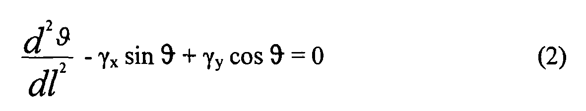
Der Winkel ϑ ist in
Für die in der obigen Gleichung (2) erwähnten γx und γy gilt: 
und 
and
Wie oben erwähnt ist EI die Biegesteifigkeit des Instruments, wobei E das Elastizitätsmodul ist und I von der Geometrie des Instruments abhängt und als Querschnitts-Trägheitsmoment bezeichnet werden kann. Für rechteckförmige Querschnitte ergibt sich beispielsweise ein I, das von dem oben in der Gleichung (1) erwähnten abweicht. Die Größe "1" bezeichnet die Länge von dem ersten Ende 9a zu einem Punkt P. Die Lage des Punkts P lässt sich somit durch die Länge 1 und durch den Winkel ϑ beschreiben.As mentioned above, EI is the flexural rigidity of the instrument, where E is the modulus of elasticity and I depends on the geometry of the instrument and may be referred to as the cross-sectional moment of inertia. For rectangular cross-sections, for example, an I, which differs from that mentioned above in the equation (1) results. The size "1" denotes the length from the
Die obige Gleichung (2) kann integriert werden und man erhält dann: 
Wobei "c" eine Konstante ist und durch die Randbedingung d ϑ /dl = γy xe bestimmt werden kann, die am ersten Ende 9a des Instruments, also am Ursprung des Koordinatensystems gilt. An dem Punkt Pe gilt ϑ = ϑe und die Länge des Instruments 9 lässt sich wie folgt berechnen: 
In der obigen Gleichung sind die Variablen ϑe, γ x und γ y unbekannt. Diese drei unbekannten Variablen können durch die folgenden Bedingungen berechnet werden: 


Bei der letzten Gleichung geht die Randbedingung ein, dass die Krümmung des Instruments oder genauer die Änderung des Winkels ϑ am Punkt Pe, also bei ϑ = ϑe verschwindet.In the last equation, the boundary condition is that the curvature of the instrument or more precisely the change of the angle θ disappears at the point P e , ie at θ = θ e .
Sind nun mit Hilfe der obigen Gleichungen (5), (6) und (7) die unbekannten Variablen ϑe, γx und γy berechnet, so lässt sich mit Hilfe der Gleichung (4) die Länge des Instruments berechnen.Now, with the aid of the above equations (5), (6) and (7), if the unknown variables θ e , γ x and γ y are calculated, the length of the instrument can be calculated using equation (4).
Bei dieser Berechnung wurde berücksichtigt, dass die Biegung des Instruments in einer Ebene erfolgt. Die Koordinaten in der Ebene werden durch das kartesische Koordinatensystem mit den Achsen x und y beschrieben. Die Punkte in der Ebene können darüber hinaus durch die Koordinaten ϑ und 1 beschrieben werden. Weiter wird angenommen, dass sich das Instrument frei in dem passenden Loch 8 in dem Kalibriergerät 7 drehen kann, sodass keine zusätzlichen Kräfte, insbesondere Verdrillungskräfte entstehen. Man nimmt also an, dass die Verbiegung des Instruments 9 lediglich in der xy-Ebene erfolgt und sonst keine Verformungskräfte wirken.This calculation took into account that the bending of the instrument takes place in one plane. The coordinates in the plane are described by the Cartesian coordinate system with the axes x and y. The points in the plane can also be described by the coordinates θ and 1. It is further believed that the instrument can rotate freely in the mating hole 8 in the
Die Kraft, die auf das Ende 9b am Punkt Pe wirkt ist die Kraft F, die in zwei Komponenten Fx (also die in x-Richtung wirkende Komponente) und Fy (also die in y wirkende Komponente) zerlegt werden kann. Man nimmt an, dass die Richtung der Kraft F mit der oben beschriebenen Tangente T übereinstimmt. Dies ist eine realistische Annahme, da mit Hilfe des Halters 10 das Instrument 9 in der Praxis beispielsweise in eine Körperstruktur eingeführt werden soll, wobei auf das Instrument 9 in Richtung der Tangente T mit dem Halter 10 eine Druckkraft ausgeübt wird, um das Instrument 9 weiter in der Körperstruktur voranzutreiben. Es wird also davon ausgegangen, dass keine Knickkräfte und Drehmomente auf das Instrument 9 ausgeübt werden, die zu einem Knicken des Instruments 9 am Montageende 11 (also bei Pe) führen können.The force acting on the
Bei einer weiteren Ausführungsform der Erfindung ist ein Kraftsensor bei der Halteeinrichtung 10 vorgesehen. Der Kraftsensor ist insbesondere in der Nähe des Montageendes 11. Der Kraftsensor misst vorzugsweise den Betrag der Kraft, der zwischen dem Instrument 9 und dem Halter 10 wirkt. Der Kraftmesser (Kraftsensor) misst insbesondere den Betrag der Kraft und vorzugsweise auch noch die Richtung der Kraft. Ist der Kraftsensor vorgesehen, so kann die Kraft Fx und Fy bestimmt werden. Somit kann aus den obigen Gleichungen (2a) und (2b) γx und γy berechnet werden. Dies vereinfacht die Bestimmung der Länge L mit Hilfe der Gleichungen (4) bis (7).In a further embodiment of the invention, a force sensor is provided in the holding
Ist nun die Länge des Instruments bekannt, so kann dies bei der Verwendung des Instruments ausgenutzt werden, um mögliche Positionen des ersten Endes des Instruments anzuzeigen, falls diese unbekannt sind. Man geht also von der Situation aus, dass das zweite Ende an dem Halter 10 angebracht ist und von einem Bediener (Operateur) das Instrument beispielsweise in eine Körperstruktur eingeführt wird. Die Lage des ersten Endes ist dann unbekannt und kann aber mittels der vorliegenden Erfindung wie folgt berechnet werden. Eine bekannte Größe ist nun die Länge L des Instruments. Weiter wird angenommen, dass eine bestimmte Kraft in die Richtung der Längserstreckung des Instruments, also mit einem Winkel ϑ = ϑe wirkt. Ein Beispiel für eine Situation in der Praxis, bei der mittels des Halters 10 das Instrument 9 in eine Körperstruktur 40 eingeführt wird, ist in
Für eine gegebene Kraft mit Betrag F ergibt sich somit eine mögliche Biegung des Instruments.For a given force of magnitude F there is thus a possible bend in the instrument.
Bei dem in
Erfindungsgemäß wird deshalb vorzugsweise die Datenverarbeitungseinrichtung 30 mit einer Anzeige verbunden, die z. B. die kalibrierte und registrierte Körperstruktur 40 zeigt, die beispielsweise mit einer Markereinrichtung 42 verbunden ist, und/oder einen Konus mit möglichen Positionen des ersten Endes 9a, 9a' und 9a'' und/oder möglichen Verläufen des Instruments gemäß den Linien 9, 9' und 9'' vom ersten Ende bis zum zweiten Ende des Instruments oder einen Abschnitt der möglichen Verläufe. Dem Operateur ist somit ermöglicht, ohne Einsatz eines Röntgengeräts das Risiko zu beurteilen, mit dem Ende 9a in einen unerwünschten Bereich zu kommen. Bei dem in
Claims (14)
mit einem Halter (10) zum Halten des Instruments (9), das ein erstes und zweites Ende (9a, 9b) aufweist und eine erste Markereinrichtung (12) aufweist, wobei das zweite Ende (9b) an dem Halter (10) angebracht ist;
mit einem Kalibriergerät (7), das eine zweite Markereinrichtung (1, 2,3) und mindestens eine Öffnung (8, 8a, 8b, 8c) vorgegebener Form und Tiefe zum Einführen des ersten Endes (9a) aufweist;
mit einer Detektionseinrichtung (20) zum Detektieren einer ersten Lage der ersten Markereinrichtung (12) und einer zweiten Lage der zweiten Markereinrichtung (1, 2,3);
mit einer Datenverarbeitungseinrichtung (30) zum Bestimmen einer Länge des Instruments (9)
basierend auf der detektierten ersten und zweiten Lage,
basierend auf Information über den Querschnitt des Instruments (9),
basierend auf Informationen über die Elastizität (E) des Materials des Instruments (9),
basierend auf der relativen Lage zwischen dem zweiten Ende (9b) und der ersten Markereinrichtung (12) und
basierend auf der relativen Lage zwischen der zweiten Markereinrichtung (12) und der mindestens einen Öffnung (8).Marker navigation system for the determination of flexible, long instruments (9), in particular medical instruments, which can be both rectilinear and curvilinear in their extension,
comprising a holder (10) for holding the instrument (9) having first and second ends (9a, 9b) and having a first marker means (12), the second end (9b) being attached to the holder (10) ;
a calibration device (7) having a second marker means (1, 2, 3) and at least one opening (8, 8a, 8b, 8c) of predetermined shape and depth for insertion of the first end (9a);
a detection device (20) for detecting a first position of the first marker device (12) and a second layer of the second marker device (1, 2, 3);
with a data processing device (30) for determining a length of the instrument (9)
based on the detected first and second position,
based on information about the cross-section of the instrument (9),
based on information about the elasticity (E) of the material of the instrument (9),
based on the relative position between the second end (9b) and the first marker means (12) and
based on the relative position between the second marker means (12) and the at least one aperture (8).
die möglichen Krümmungen und/oder den Bereich der möglichen Krümmungen des Instruments anzeigt.A marker navigation system according to claim 8, further comprising a display indicating the possible locations and / or the range of possible locations of the first end of the instrument and / or
indicates the possible curvatures and / or the range of possible curvatures of the instrument.
mit einem Halter (10) zum Halten des Instruments (9) das ein erstes und zweites Ende (9a, 9b) aufweist und eine erste Markereinrichtung (12) aufweist, wobei das zweiten Ende (9b) an dem Halter (10) angebracht ist;
mit einer Detektionseinrichtung (20) detektieren einer ersten Lage einer ersten Markereinrichtung;
mit einer Datenverarbeitungseinrichtung (30) zum Bestimmen der möglichen Lagen des ersten Endes (9a) des Instruments (9)
basierend auf der detektierten ersten Lage,
basierend auf Information über den Querschnitt des Instruments (9),
basierend auf Information über die Elastizität (E) des Materials des Instruments (9),
basierend auf der relativen Lage zwischen dem zweiten Ende (9b) und der ersten Markereinrichtung (12) und
basierend auf einer Kraft, die auf das Instrument wirkt oder von der angenommen wird, dass sie auf das Instrument wirkt.Marker navigation system for determining the possible position of flexible, long instruments (9), in particular medical instruments, which in their extension can be both rectilinear and curvilinear,
a holder (10) for holding the instrument (9) having first and second ends (9a, 9b) and having first marker means (12), the second end (9b) being attached to the holder (10);
with a detection device (20) detecting a first position of a first marker device;
with a data processing device (30) for determining the possible positions of the first end (9a) of the instrument (9)
based on the detected first position,
based on information about the cross-section of the instrument (9),
based on information about the elasticity (E) of the material of the instrument (9),
based on the relative position between the second end (9b) and the first marker means (12) and
based on a force that acts on the instrument or is believed to act on the instrument.
wobei das Verfahren die folgenden Schritte umfasst:
the method comprising the following steps:
Priority Applications (3)
| Application Number | Priority Date | Filing Date | Title |
|---|---|---|---|
| EP06023012A EP1925265B1 (en) | 2006-11-06 | 2006-11-06 | Length determination of a long flexible instrument |
| DE502006005876T DE502006005876D1 (en) | 2006-11-06 | 2006-11-06 | Determining the length of a flexible, long instrument |
| US11/935,571 US20080139916A1 (en) | 2006-11-06 | 2007-11-06 | Determining the length of a long, flexible instrument |
Applications Claiming Priority (1)
| Application Number | Priority Date | Filing Date | Title |
|---|---|---|---|
| EP06023012A EP1925265B1 (en) | 2006-11-06 | 2006-11-06 | Length determination of a long flexible instrument |
Publications (2)
| Publication Number | Publication Date |
|---|---|
| EP1925265A1 true EP1925265A1 (en) | 2008-05-28 |
| EP1925265B1 EP1925265B1 (en) | 2010-01-06 |
Family
ID=37890387
Family Applications (1)
| Application Number | Title | Priority Date | Filing Date |
|---|---|---|---|
| EP06023012A Expired - Fee Related EP1925265B1 (en) | 2006-11-06 | 2006-11-06 | Length determination of a long flexible instrument |
Country Status (3)
| Country | Link |
|---|---|
| US (1) | US20080139916A1 (en) |
| EP (1) | EP1925265B1 (en) |
| DE (1) | DE502006005876D1 (en) |
Cited By (2)
| Publication number | Priority date | Publication date | Assignee | Title |
|---|---|---|---|---|
| CN112716605A (en) * | 2021-03-31 | 2021-04-30 | 上海龙慧医疗科技有限公司 | Two-way self-locking lever of ball socket type positioner |
| US20230045275A1 (en) * | 2021-08-05 | 2023-02-09 | GE Precision Healthcare LLC | Methods and system for guided device insertion during medical imaging |
Families Citing this family (10)
| Publication number | Priority date | Publication date | Assignee | Title |
|---|---|---|---|---|
| US9449149B2 (en) | 2011-05-11 | 2016-09-20 | Brainlab Ag | Method for optimising local drug delivery |
| US10292775B2 (en) * | 2011-08-26 | 2019-05-21 | Brainlab Ag | Systems and method for determining the shape of a surgical instrument and surgical instruments having a deformable body |
| US20140235999A1 (en) * | 2011-08-26 | 2014-08-21 | Brainlab Ag | Method for determining the shape of a surgical instrument and surgical instrument having a deformable body |
| US8646921B2 (en) | 2011-11-30 | 2014-02-11 | Izi Medical Products | Reflective marker being radio-opaque for MRI |
| US8661573B2 (en) | 2012-02-29 | 2014-03-04 | Izi Medical Products | Protective cover for medical device having adhesive mechanism |
| US9468504B2 (en) * | 2013-02-27 | 2016-10-18 | B & D Dental Corporation | Dental cutting system and method with remote cutting guide |
| DE102013222230A1 (en) | 2013-10-31 | 2015-04-30 | Fiagon Gmbh | Surgical instrument |
| CN108024693B (en) * | 2015-09-10 | 2021-07-09 | 直观外科手术操作公司 | System and method for utilizing tracking in image guided medical procedures |
| EP3719749A1 (en) | 2019-04-03 | 2020-10-07 | Fiagon AG Medical Technologies | Registration method and setup |
| CN111110351B (en) * | 2020-01-10 | 2021-04-30 | 北京天智航医疗科技股份有限公司 | Assembly and method for detecting accuracy of joint replacement surgical robotic system |
Citations (3)
| Publication number | Priority date | Publication date | Assignee | Title |
|---|---|---|---|---|
| US5921992A (en) * | 1997-04-11 | 1999-07-13 | Radionics, Inc. | Method and system for frameless tool calibration |
| WO2002036018A1 (en) * | 2000-11-03 | 2002-05-10 | Synthes Ag Chur | Determination of deformation of surgical tools |
| EP1704825A1 (en) * | 2005-03-22 | 2006-09-27 | BrainLAB AG | Guide wire navigation |
Family Cites Families (4)
| Publication number | Priority date | Publication date | Assignee | Title |
|---|---|---|---|---|
| US5122150A (en) * | 1985-03-27 | 1992-06-16 | Puig Ana E | Neurosurgical clip applier |
| DE69318304T2 (en) * | 1992-08-14 | 1998-08-20 | British Telecomm | LOCATION SYSTEM |
| US6351659B1 (en) * | 1995-09-28 | 2002-02-26 | Brainlab Med. Computersysteme Gmbh | Neuro-navigation system |
| US6497152B2 (en) * | 2001-02-23 | 2002-12-24 | Paroscientific, Inc. | Method for eliminating output discontinuities in digital pressure transducers and digital pressure transducer employing same |
-
2006
- 2006-11-06 EP EP06023012A patent/EP1925265B1/en not_active Expired - Fee Related
- 2006-11-06 DE DE502006005876T patent/DE502006005876D1/en active Active
-
2007
- 2007-11-06 US US11/935,571 patent/US20080139916A1/en not_active Abandoned
Patent Citations (3)
| Publication number | Priority date | Publication date | Assignee | Title |
|---|---|---|---|---|
| US5921992A (en) * | 1997-04-11 | 1999-07-13 | Radionics, Inc. | Method and system for frameless tool calibration |
| WO2002036018A1 (en) * | 2000-11-03 | 2002-05-10 | Synthes Ag Chur | Determination of deformation of surgical tools |
| EP1704825A1 (en) * | 2005-03-22 | 2006-09-27 | BrainLAB AG | Guide wire navigation |
Cited By (3)
| Publication number | Priority date | Publication date | Assignee | Title |
|---|---|---|---|---|
| CN112716605A (en) * | 2021-03-31 | 2021-04-30 | 上海龙慧医疗科技有限公司 | Two-way self-locking lever of ball socket type positioner |
| CN112716605B (en) * | 2021-03-31 | 2021-06-11 | 上海龙慧医疗科技有限公司 | Two-way self-locking lever of ball socket type positioner |
| US20230045275A1 (en) * | 2021-08-05 | 2023-02-09 | GE Precision Healthcare LLC | Methods and system for guided device insertion during medical imaging |
Also Published As
| Publication number | Publication date |
|---|---|
| EP1925265B1 (en) | 2010-01-06 |
| US20080139916A1 (en) | 2008-06-12 |
| DE502006005876D1 (en) | 2010-02-25 |
Similar Documents
| Publication | Publication Date | Title |
|---|---|---|
| EP1925265B1 (en) | Length determination of a long flexible instrument | |
| DE69738092T2 (en) | Curvature-sensitive catheter | |
| EP1593350B1 (en) | Tracking of intramedullary pin | |
| EP2910206B1 (en) | Set of medical instruments | |
| DE102006032127B4 (en) | Calibration method and calibration device for a surgical referencing unit | |
| DE102005042751B4 (en) | System, device and method for ad hoc tracking of an object | |
| EP1089669B1 (en) | Fiducial matching by means of fiducial screws | |
| DE2443558B2 (en) | Device for puncturing internal organs and vessels | |
| DE102008013615A1 (en) | Method and marking device for marking a guide line of a penetration instrument, control device and recording system | |
| EP1872735A1 (en) | Method for automatic identification of instruments during medical navigation | |
| EP1886641A1 (en) | Method and system for determining the position of a medical instrument in relation to a body structure | |
| EP1923015A1 (en) | Navigation system with markers for obtaining and depicting said markers' position | |
| EP2105107A1 (en) | Method for calibrating axial medicinal or medical technical instruments | |
| DE102012104973A1 (en) | Surgical instrument | |
| EP3713505A1 (en) | Guide device for biopsy needle | |
| DE102005047895B4 (en) | Method and device for determining the position of an object | |
| DE102004044285A1 (en) | System and method for determining the position of an elastic instrument used in a position tracking system | |
| DE19536180C2 (en) | Methods and devices for locating an instrument | |
| EP2051096A2 (en) | Method and device for determining the frontal layer of the pelvic bone | |
| DE19908844A1 (en) | Method and device for correlating the actual position of a marking element with the position data obtained by an imaging method | |
| DE102009017243B4 (en) | System for determining deviations of the predetermined position of an invisible feature due to deformations of implants | |
| EP3459478B1 (en) | Medical deformation device, deformation system and method for deforming an article | |
| DE102014200326A1 (en) | A method of supporting navigation of a medical instrument | |
| EP1704825B1 (en) | Guide wire navigation | |
| DE102011083360A1 (en) | Pedicle awl used during implantation of pedicle screw for spine treatment, has ultrasonic probe that is adapted to measure distance between cortical pedicle and outer layer of pedicles |
Legal Events
| Date | Code | Title | Description |
|---|---|---|---|
| PUAI | Public reference made under article 153(3) epc to a published international application that has entered the european phase |
Free format text: ORIGINAL CODE: 0009012 |
|
| 17P | Request for examination filed |
Effective date: 20061106 |
|
| AK | Designated contracting states |
Kind code of ref document: A1 Designated state(s): AT BE BG CH CY CZ DE DK EE ES FI FR GB GR HU IE IS IT LI LT LU LV MC NL PL PT RO SE SI SK TR |
|
| AX | Request for extension of the european patent |
Extension state: AL BA HR MK RS |
|
| AKX | Designation fees paid |
Designated state(s): DE FR |
|
| GRAP | Despatch of communication of intention to grant a patent |
Free format text: ORIGINAL CODE: EPIDOSNIGR1 |
|
| GRAS | Grant fee paid |
Free format text: ORIGINAL CODE: EPIDOSNIGR3 |
|
| GRAA | (expected) grant |
Free format text: ORIGINAL CODE: 0009210 |
|
| AK | Designated contracting states |
Kind code of ref document: B1 Designated state(s): DE FR |
|
| REF | Corresponds to: |
Ref document number: 502006005876 Country of ref document: DE Date of ref document: 20100225 Kind code of ref document: P |
|
| PLBE | No opposition filed within time limit |
Free format text: ORIGINAL CODE: 0009261 |
|
| STAA | Information on the status of an ep patent application or granted ep patent |
Free format text: STATUS: NO OPPOSITION FILED WITHIN TIME LIMIT |
|
| 26N | No opposition filed |
Effective date: 20101007 |
|
| REG | Reference to a national code |
Ref country code: DE Ref legal event code: R082 Ref document number: 502006005876 Country of ref document: DE Representative=s name: SCHWABE SANDMAIR MARX, DE |
|
| REG | Reference to a national code |
Ref country code: DE Ref legal event code: R081 Ref document number: 502006005876 Country of ref document: DE Owner name: BRAINLAB AG, DE Free format text: FORMER OWNER: BRAINLAB AG, 85622 FELDKIRCHEN, DE Effective date: 20131104 Ref country code: DE Ref legal event code: R082 Ref document number: 502006005876 Country of ref document: DE Representative=s name: SCHWABE SANDMAIR MARX, DE Effective date: 20131104 Ref country code: DE Ref legal event code: R082 Ref document number: 502006005876 Country of ref document: DE Representative=s name: SCHWABE SANDMAIR MARX PATENTANWAELTE RECHTSANW, DE Effective date: 20131104 |
|
| PGFP | Annual fee paid to national office [announced via postgrant information from national office to epo] |
Ref country code: FR Payment date: 20141119 Year of fee payment: 9 Ref country code: DE Payment date: 20141119 Year of fee payment: 9 |
|
| REG | Reference to a national code |
Ref country code: DE Ref legal event code: R119 Ref document number: 502006005876 Country of ref document: DE |
|
| REG | Reference to a national code |
Ref country code: FR Ref legal event code: ST Effective date: 20160729 |
|
| PG25 | Lapsed in a contracting state [announced via postgrant information from national office to epo] |
Ref country code: DE Free format text: LAPSE BECAUSE OF NON-PAYMENT OF DUE FEES Effective date: 20160601 |
|
| PG25 | Lapsed in a contracting state [announced via postgrant information from national office to epo] |
Ref country code: FR Free format text: LAPSE BECAUSE OF NON-PAYMENT OF DUE FEES Effective date: 20151130 |