EP1925222A2 - Personal protection system comprising a helmet, a hood and assembly for aligning the hood with the helmet - Google Patents
Personal protection system comprising a helmet, a hood and assembly for aligning the hood with the helmet Download PDFInfo
- Publication number
- EP1925222A2 EP1925222A2 EP08001739A EP08001739A EP1925222A2 EP 1925222 A2 EP1925222 A2 EP 1925222A2 EP 08001739 A EP08001739 A EP 08001739A EP 08001739 A EP08001739 A EP 08001739A EP 1925222 A2 EP1925222 A2 EP 1925222A2
- Authority
- EP
- European Patent Office
- Prior art keywords
- air
- user
- face shield
- helmet assembly
- helmet
- Prior art date
- Legal status (The legal status is an assumption and is not a legal conclusion. Google has not performed a legal analysis and makes no representation as to the accuracy of the status listed.)
- Granted
Links
Images


Classifications
-
- A—HUMAN NECESSITIES
- A41—WEARING APPAREL
- A41D—OUTERWEAR; PROTECTIVE GARMENTS; ACCESSORIES
- A41D13/00—Professional, industrial or sporting protective garments, e.g. surgeons' gowns or garments protecting against blows or punches
- A41D13/05—Professional, industrial or sporting protective garments, e.g. surgeons' gowns or garments protecting against blows or punches protecting only a particular body part
- A41D13/11—Protective face masks, e.g. for surgical use, or for use in foul atmospheres
- A41D13/1107—Protective face masks, e.g. for surgical use, or for use in foul atmospheres characterised by their shape
- A41D13/1153—Protective face masks, e.g. for surgical use, or for use in foul atmospheres characterised by their shape with a hood
-
- A—HUMAN NECESSITIES
- A42—HEADWEAR
- A42B—HATS; HEAD COVERINGS
- A42B3/00—Helmets; Helmet covers ; Other protective head coverings
- A42B3/04—Parts, details or accessories of helmets
- A42B3/28—Ventilating arrangements
- A42B3/286—Ventilating arrangements with forced flow, e.g. by a fan
-
- A—HUMAN NECESSITIES
- A62—LIFE-SAVING; FIRE-FIGHTING
- A62B—DEVICES, APPARATUS OR METHODS FOR LIFE-SAVING
- A62B18/00—Breathing masks or helmets, e.g. affording protection against chemical agents or for use at high altitudes or incorporating a pump or compressor for reducing the inhalation effort
- A62B18/04—Gas helmets
- A62B18/045—Gas helmets with fans for delivering air for breathing mounted in or on the helmet
Definitions
- the exhaust fan creates excessive strain, and therefore fatigue, in the neck of the user because the exhaust fan is spaced away from the neck of the user.
- the subject invention also incorporates at least two helmet air exits, preferably a front and rear air helmet air exit for distributing air from the air flow channel toward the head of the user. More specifically, the front and rear air exits are disposed at the front and rear sections of the helmet assembly, respectively. The front and rear air exits are in fluid communication with the air flow channel and the air outlets. The front air exit distributes air from the air flow channel toward a front, or face, of the head of the user, and the rear air exit distributes air from the air flow channel toward a back, or neck, of the head of the user. As such, a single fan is utilized to distribute air toward both the face and the neck of the user. The air outlet or outlets of the scroll housing completely balance the air flow about the head of the user between the front and rear air exits.
- a front and rear air helmet air exits are disposed at the front and rear sections of the helmet assembly, respectively.
- the front and rear air exits are in fluid communication with the air flow channel and the air outlets.
- the front air exit distributes
- the fan is disposed at the rear section of the base section of the helmet assembly, the fan is not spaced away from the user's neck and strain and fatigue in the user is minimized.
- the subject invention further includes a face shield mounted to the head portion of the gown to cover the facial opening. As such, the user can view through the head portion of the gown.
- the face shield includes either a mounting mechanism or a first visual indicator.
- the subject invention incorporates at least one air bleed valve 82 in the scroll housing 48 to influence the amount, or the volume, of air flowing into the air flow channel 26 from each of the air outlets 66. It is to be understood that, although there is only one air bleed valve 82 shown in Figure 4 , the subject invention may alternatively incorporate more than one air bleed valve.
- the air bleed valve 82 influences the volume of air flowing to the rear air exit 78 thereby affecting the volume of air flowing to the rear air exit78 that is distributed primarily toward the back of the head 14 of the user.
- the mounting mechanism 108 is preferably centered on the face shield 96.
- the mounting mechanism 108 supports the face shield 96 on the helmet assembly 12.
- the mounting mechanism 108 is an aperture 110 formed within the face shield 96. The function of the mounting mechanism 108, the aperture 110, will be described further below.
- the fan 50 rotates at 2000 RPM.
- the controller 118 selectively activates and deactivates the power supply 70 in a 30 : 70 ratio. That is, the controller 118 turns the power supply 70 ON 30% of the time and OFF 70% of the time.
- first and second ends can be manipulated toward each other even if the first end 144 is fixed and the second end 146 is the only end of the strap 142 that is manipulated, i.e., moved, by the adjustment device 154, or even if the second end 146 is fixed and the first end 144 is the only end of the strap 142 that is manipulated, i.e., moved, by the adjustment device 154.
- said assembly may include a front air exit disposed at said front section of said base section for distributing air from said air flow channel toward a front of the head of the user, and a rear air exit disposed at said rear section of said base section for distributing air from said air flow channel toward a back of the head of the user.
- an intake grid mounted to said outer shell may be included such that said gown covers said intake grid to operate as said filter medium for filtering air drawn into said scroll housing.
- said intake grid may further include a top surface spaced from said outer shell for retaining said filter medium away from said outer shell.
- said intake grid may be contoured to said outer shell between said front section and said rear section of said base section to maximize an effective intake area for said filter medium to filter air drawn into said scroll housing.
Abstract
Description
- The subject invention generally relates to an air filtration system for filtering air between a head and body of a user and an environment external to the user. The air filtration system is utilized in the medical profession during surgical procedures. The subject invention more specifically relates to a helmet assembly and gown for use in the air filtration system.
- Air filtration systems and helmet assemblies utilized in the air filtration systems are known in the art. As indicated above, air filtration systems and helmet assemblies are worn by users throughout the medical profession, such as surgeons, during surgical procedures for filtering air between a head and body of the surgeon and an external environment, such as a clean room.
- Conventional air filtration systems and helmet assemblies are deficient for one reason or another. For example,
United States Patent No. 5, 592, 936 to Thomas, Jr. et al. discloses an air filtration system and helmet assembly that draws air through a filter medium into the helmet assembly and through an intake grid where the air is then channeled through an air flow channel over a face of the user. The air filtration system and helmet assembly of this patent are deficient in that air is not distributed completely about the head of the user. That is, air is not distributed to a back of the head, toward a neck, of the user. Further, the intake grid is deficient in that the grid does not extend between a front and rear section of the helmet assembly to maximize an effective intake area for the filter medium. - A further example of a conventional air filtration system and helmet assembly is disclosed in
United States Patent No. 5, 054, 480 to Bare et al. This patent discloses an air filtration system and helmet assembly that draws air into the helmet assembly via an intake fan, and exhausts air from the air filtration system and helmet assembly via an exhaust fan disposed at the rear section of the helmet assembly spaced away from the neck of the user. The air filtration system and helmet assembly of this patent is deficient in that they are overly heavy due to the additional fan required to exhaust air. - Furthermore, the exhaust fan creates excessive strain, and therefore fatigue, in the neck of the user because the exhaust fan is spaced away from the neck of the user.
- The conventional air filtration system and helmet assembly disclosed in
United States Patent No. 5,711,033 to Green et al. is also deficient. This patent discloses an air filtration system and helmet assembly that draws air into the helmet assembly through an intake fan and scroll housing disposed at a rear section of the helmet assembly. The air filtration and helmet assembly of this patent is deficient because the intake fan and scroll housing are spaced away from the neck of the user. Further, the scroll housing in this patent includes only one air outlet to distribute air about the head of the user resulting in less balanced air flow throughout the helmet assembly. Additional drawbacks of such an air filtration system and helmet assembly including only one air outlet from the scroll housing are excessive fog build-up and poorer heat dissipation in the helmet assembly. - Other conventional air filtration systems and helmet assemblies are also deficient for the following reasons. First, these conventional air filtration systems and helmet assemblies do not assist a single user in self-gowning as the surgeon maintains sterility. That is, these air filtration systems and helmet assemblies do not include a positioning and supporting system that automatically centers a face shield over the helmet assembly and that supports an entire weight of the gown and face shield.
- Instead, the conventional air filtration systems and helmet assemblies merely utilize hook-and-loop fasteners randomly places around the helmet assembly to connect the face shield to the helmet assembly in any orientation. Furthermore, randomly-placed hook-and-loop fasteners do not automatically center the face shield and do not support the entire weight of the gown and the face shield as the surgeon self-gowns. Instead, as the user self-gowns, he or she must repeatedly adjust the face shield in order to center the face shield. This is time consuming and burdensome.
- Secondly, it is generally understood that the amount of air flowing into the helmet assembly is critical for anti-fogging and heat control purposes. However, the air filtration systems and helmet assemblies of the prior art do not assist the surgeon in recognizing the amount, or volume, of air flowing into the helmet assembly. That is, these air filtration systems and helmet assemblies do not provide audible indication to the surgeon of the volume of air flowing into the helmet assembly during any particular surgical procedure.
- Thirdly, as discussed above, it is ideal to position and maintain any fans in the air filtration system and helmet assembly as directly over, and not spaced from, the neck of the user as possible in order to minimize strain and fatigue. The prior art air filtration systems and helmet assemblies do not incorporate a strap flexibly connected to the front section of the helmet assembly such that the strap is pulled from the front section of the helmet assembly and the weight of any fans is maintained over the user's neck when the helmet assembly is adjusted to fit various sized heads.
- Due to the inefficiencies identified in such conventional air filtration systems and helmet assemblies, it is desirable to implement a novel air filtration system and helmet assembly that utilizes a single fan to distribute air toward both the face and the neck of the user and that includes a scroll housing that includes at least two air outlets for complete balancing of the air flow about the head of the user. It is also desirable to dispose the fan in the helmet assembly such that it is not spaced away from the neck of the user to minimize strain, and to include an intake grid that extends between front and rear sections of the helmet assembly to maximize the effective intake area for filtering the air. Finally, it is desirable to implement an air filtration system and helmet assembly that includes a positioning and supporting system to assist the user in self-gowning, that includes audible indication to the user of the volume of air flowing into the helmet, and that includes a strap that can be adjusted to fit different sizes of heads while maintaining the weight of the helmet assembly over the neck of the user.
- An air filtration system for filtering air and a helmet assembly for use in the air filtration system is disclosed. The air filtration system and helmet assembly are utilized in the medical profession during surgical procedures to filter air between a head and body of a user, such as a surgeon, and an environment external to the user. As appreciated by those skilled in the art, the subject invention, in addition to air filtering, assists in controlling carbon dioxide concentration, dissipating heat, and anti-fogging within the helmet assembly. It is to be understood that the subject invention can also be utilized in other situations requiring filtered air including, but not limited to, the manufacturing of semi-conductor chips and other computer components in manufacturing clean rooms.
- The air filtration system and helmet assembly include an inner structural shell and an outer structural shell. The outer structural shell extends from the inner structural shell to define at least one air flow channel between the inner and outer shells for channeling air about the head of the user. The helmet assembly further includes a base section and a facial section extending from the base section to define a facial opening.
- A fan module is mounted to at least one of the inner and outer shells, and a scroll housing is mounted adjacent the fan module. More specifically, the fan module includes a fan and a motor, and the scroll housing includes at least one air inlet and at least one, preferably at least two, air outlets. The fan module, including both the fan and the motor, is disposed at the rear section of the base section. In operation, the fan module, specifically the fan, draws air into the air inlet and distributes air out of the scroll housing through the air outlet or outlets and into the air flow channel.
- The subject invention also incorporates at least two helmet air exits, preferably a front and rear air helmet air exit for distributing air from the air flow channel toward the head of the user. More specifically, the front and rear air exits are disposed at the front and rear sections of the helmet assembly, respectively. The front and rear air exits are in fluid communication with the air flow channel and the air outlets. The front air exit distributes air from the air flow channel toward a front, or face, of the head of the user, and the rear air exit distributes air from the air flow channel toward a back, or neck, of the head of the user. As such, a single fan is utilized to distribute air toward both the face and the neck of the user. The air outlet or outlets of the scroll housing completely balance the air flow about the head of the user between the front and rear air exits.
- Further, because the fan is disposed at the rear section of the base section of the helmet assembly, the fan is not spaced away from the user's neck and strain and fatigue in the user is minimized.
- The air filtration system further includes a gown having a body portion and a head portion. The body portion covers at least a portion of the body of the user and the head portion covers the base section of the helmet assembly. The head portion of the gown operates as a filter medium to filter air between the user and the external environment. The gown also includes a skirt. More specifically, the skirt is removably attached to the body portion of the gown exclusively at a front of the gown. An intake grid is mounted to the outer shell of the helmet assembly for user with the gown. The intake grid is contoured to the outer shell between the front section and the rear section of the base section to maximize an effective intake area for the filter medium to filter air drawn into the scroll housing.
- The subject invention further includes a face shield mounted to the head portion of the gown to cover the facial opening. As such, the user can view through the head portion of the gown. Depending on the particular embodiment of the subject invention, the face shield includes either a mounting mechanism or a first visual indicator. These will be described further below.
- Also depending on the particular embodiment, the base section of the helmet assembly includes either a mounting device or a second visual indicator positioned, preferably centered, relative to the facial opening. If the helmet assembly includes the mounting device, the mounting device interlocks with the mounting mechanism on the face shield. As such, the subject invention provides a positioning and supporting system that automatically centers the face shield over the facial opening and that preferably supports the entire weight of the gown in order to assist the single user in self-gowning as the user maintains sterility. On the other hand, if the helmet assembly includes the second visual indicator, then the second visual indicator aligns with the first visual indicator on the face shield. As such, the subject invention provides a visual positioning system that automatically centers the face shield over the facial opening thereby assisting the single user is self-gowning as the user maintains sterility.
- The subject invention also includes a controller that operates with a power supply to control the amount, or volume, of air into the air filtration system and helmet assembly and to provide audible indication of the volume of air to the user while the user is wearing the air filtration system and helmet assembly during the surgical procedure. Preferably, the power is integrally disposed within the helmet assembly.
- The air filtration system and helmet assembly of the subject invention also include a strap flexibly connected to the helmet assembly such that the strap is pulled from the front section of the helmet assembly. As a result, the weight of the fan is maintained over the user's neck when the helmet assembly is adjusted to fit various sized heads.
- The subject invention further includes a method for maintaining a constant volume of air flowing into an air filtration system during the entire use of the air filtration system. The method includes the steps of selectively activating and deactivating the power supply at a first activation rate to distribute a required voltage to the motor. This step establishes a rotational speed for the fan that correlates to the constant volume of air flowing into the air filtration system. Next, the method monitors the back electromotive force of the motor of the helmet assembly to determine the rotational speed of the fan as well as when the rotational speed of the fan has stabilized for some predetermined period of time. The voltage of the power supply is monitored after the rotational speed of the fan has stabilized for the predetermined period of time.
- Finally, the power supply is selectively activated and deactivated at a second activation rate as the monitored voltage of the power supply decreases. This step sustains the required voltage that is distributed to the motor such that the constant volume of air flowing into the air filtration system is maintained throughout the entire use of the air filtration system.
- Accordingly, the subject invention provides an air filtration system and helmet assembly that overcomes the deficiencies in the prior art as identified above.
- Other advantages of the present invention will be readily appreciated as the same becomes better understood by reference to the following detailed description when considered in connection with the accompanying drawings wherein:
-
Figure 1 is a perspective view of a helmet assembly mounted on a head of a user of the assembly; -
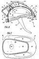
Figure 2 is an exploded perspective view of the helmet assembly; -
Figure 3 is a partially cross-sectional side view illustrating a base section and a facial section of the helmet assembly and an air flow channel and air exits within the helmet assembly; -
Figure 4 is a perspective view of a fan module and scroll housing of the subject invention including at least one air outlet from the scroll housing; -
Figure 5 is a perspective view of the scroll housing including more than one air outlet from the scroll housing; -
Figure 6 is an exploded view of the fan module and scroll housing; -
Figure 7 is a top view of the helmet assembly; -
Figure 8 is a side view of the helmet assembly and an air filtration system including a gown and face shield; -
Figure 9 is a perspective view of the helmet assembly illustration a positioning and supporting system including a mounting clip supporting the face shield via an aperture in the face shield ; -
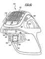
Figure 10 is a perspective view from a rear of the helmet assembly illustrating an intake grid and first and second motor controls extending at different heights from an outer shell of the helmet assembly ; -
Figure 11 is a perspective view from the rear of the helmet assembly illustrating a rear support, strap, and adjustment knob to facilitate a proper fit of the helmet assembly on various sized heads of users; -
Figure 12 is an enlarged view of the rear support and the adjustment knob; -
Figure 13 is an enlarged perspective view of an inner surface of the adjustment knob illustrating a pinion and a plurality of teeth; and -
Figure 14 is an enlarged perspective view of the rear support illustrating a flexible support bar and a detent that mates with the plurality of teeth on the adjustment knob. - Referring to the Figures, wherein like numerals indicate like or corresponding parts throughout the several views, an air filtration system and helmet assembly are generally disclosed at 10 and 12, respectively. Referring to
Figure 1 , theair filtration system 10 filters air between ahead 14 andbody 16 of a user and an environment external to the user and includes thehelmet assembly 12 mounted to thehead 14 of a user. Thehelmet assembly 12 distributes air about thehead 14 of the user as will be described below. More specifically, thehelmet assembly 12 distributes air toward both a front of thehead 14, i.e., the face, of the user, and a back of thehead 14, i.e., the neck, of the user. - Referring now to
Figures 2 and3 , thehelmet assembly 12 includes an innerstructural shell 18 and an outerstructural shell 20. Theinner shell 18 includes acover surface 22 and a rear facing 24 which extend to theouter shell 20. Thecover surface 22 and rear facing 24 will be discussed further below. Theouter shell 20 is spaced apart from theinner shell 18 and extends from theinner shell 18 to define at least oneair flow channel 26 between the inner andouter shells air flow channel 26. However, the preferred embodiment includes a single unitaryair flow channel 26 and the subject invention will be described below in terms of thisair flow channel 26. - The
air flow channel 26 channels air about thehead 14 of the user. The inner andouter shells air flow channel 26 from a two-sheet thermoforming process which improves the structural strength of the inner andouter shells outer shells outer periphery 28, and in the two-sheet thermoforming process, the inner andouter shells outer peripheries 28. Theair flow channel 26 is subsequently thermoformed between the pinchedouter peripheries 28. As shown best inFigure 7 ,dissipation cavities 30 are disposed at opposite lateral sides of the inner andouter shells air flow channel 26 and from the user out through thehelmet assembly 12. - The
helmet assembly 12 further includes abase section 32 having afront section 34 and arear section 36. The inner andouter shells rear sections air flow channel 26. Thecover surface 22 and the rear facing 24 of theinner shell 18 extend to theouter shell 20 at therear section 36 of thebase section 32. Also, at therear section 36 of thebase section 32, a mountingcavity 38 is formed between thecover surface 22 of theinner shell 18 and theouter shell 20. The mountingcavity 38 will be discussed further below. The inner andouter shells base section 32. It is understood that thebase section 32 is the portion of thehelmet assembly 12 that is mounted over thehead 14 of the user. As such, it is also understood that thefront section 34 of thebase section 32 is at the face of the user as the user wears thehelmet assembly 12, and therear section 36 of thebase section 32 is at the neck of the user as the user wears thehelmet assembly 12. - The
helmet assembly 12 also includes afacial section 40 extending from thebase section 32 to define afacial opening 42. Thefacial section 40 of thehelmet assembly 12 is achin bar 44. Preferably, thechin bar 44 is flexible and is formed of plastic. The chin bar may also be formed of a polypropylene component. The flexibility of thechin bar 44 protects the user's face and also absorbs impact when the user contacts an external object with thehelmet assembly 12. - Referring to
Figures 2 through 6 , theair filtration system 10 andhelmet assembly 12 further include afan module 46 mounted to at least one of the inner andouter shells scroll housing 48 mounted in thehelmet assembly 12 adjacent thefan module 46. More specifically, both thefan module 46 and thescroll housing 48 are disposed within the mountingcavity 38 at therear section 36 of thehelmet assembly 12. Disposing thefan module 46 and thescroll housing 48 in the mountingcavity 38 is space-saving, reduces the overall weight of thehelmet assembly 12 because additional mounting connections are not required, and minimizes strain and fatigue on thehead 14 and the neck of the user. - The
fan module 46 includes afan 50 and amotor 52 and is disposed at therear section 36 of thebase section 32. Thefan 50 includes a plurality ofcurved blades 54 and ahub portion 56. Thecurved blades 54 of thefan 50 encourage air into thescroll housing 48. Themotor 52 includes anoutput 58, or drive shaft, that is operatively connected to thefan 50 to drive thefan 50 at a plurality of rotational speeds correlating to an amount, or a volume, of air flowing into the air flow channel26. As appreciated, the rotational speeds of thefan 50 can be measured in revolutions per minute (RPMs). - Referring primarily to
Figures 4 and 5 , thescroll housing 48 includes abase portion 60 and anouter wall 62 circumferentially extending around thebase portion 60. - The
scroll housing 48 further includes at least oneair inlet 64 and at least oneair outlet 66. In the most preferred embodiment of the subject invention, the scroll housing includes a plurality ofair outlets 66. That is, in this embodiment the scroll housing includes at least twoair outlets 66. Other specific embodiments of the subject invention may also only include thefan module 46 without thescroll housing 48. In such embodiments, the at least one air inlet and the at least one air outlet can be described as components of thefan module 46. - In operation, the
motor 52 rotates thefan 50 to draw air into theair inlet 64 of thescroll housing 48 and distributes air out of thescroll housing 48 through theair outlet 66 oroutlets 66 and into theair flow channel 26 where the air is distributed about thehead 14 of the user. Thescroll housing 48 also includes at least oneair flow cutoff 68 which cuts the air as thefan 50 moves the air within thescroll housing 48. More specifically, as shown in the Figures, the subject invention incorporates several air flow cutoffs 68 in thescroll housing 48 to cut the air. Apower supply 70 is incorporated in the subject invention to power themotor 52 to rotate thefan 50 via themotor output 58. - Preferably, the
power supply 70 is a rechargeable DC battery. Also preferred, thepower supply 70 is disposed within, i.e., integrated into, thehelmet assembly 12. In such a case, thepower supply 70 is referred to as anintegral power supply 71 as shown inFigure 3 . Alternatively, thepower supply 70 can be mounted to thebody 16 of the user as shown inFigure 8 . Thepower supply 70 powers themotor 52 through pulse width modulation (PWM) which will be discussed further below. The design of thescroll housing 48 provides more efficient movement of air with less power being required from thepower supply 70 overall. Furthermore, in addition to such reduced power requirements, thescroll housing 48 provides that sufficient air flow can be maintained with overall less air velocity. This results in a morequiet helmet assembly 12. - More specifically, the
fan 50 of thefan module 46 is rotatably mounted to thebase portion 60 of thescroll housing 48 within theouter wall 62 of thescroll housing 48 to draw air into theair inlet 64. As best shown inFigures 2 and7 , theair inlet 64 of thescroll housing 48 is integrally formed within theouter shell 20 of thehelmet assembly 12 for drawing air into thescroll housing 48. However, it is to be understood that theair inlet 64 is not required to be integrally formed within theouter shell 20 of thehelmet assembly 12. That is, in an alternative embodiment of the subject invention, an external structure, not shown in the Figures, can be mounted external to thehelmet assembly 12 to establish theair inlet 64 of thescroll housing 48 for drawing air into thescroll housing 48. - Referring now to
Figures 4 through 6 , thescroll housing 48 further includes asupport pedestal 72 protruding from thebase portion 60. As shown in the Figures, thesupport pedestal 72 is integrally formed as a part of thescroll housing 48 to protrude from thebase portion 60. Alternatively, it is also to be understood that thesupport pedestal 72 can be a separate part. That is, thesupport pedestal 72 can be a separate part that is mounted or connected to thebase portion 60 of thescroll housing 48 via connecting screws, snap fit, and the like. Thehub portion 56 of thefan 50 is rotatably mounted in thescroll housing 48 on thesupport pedestal 72 by screws or other fasteners. Themotor 52 of thefan module 46 is mounted within anunderside 74 of thesupport pedestal 72 between thesupport pedestal 72 and thecover surface 22 of theinner shell 18 for space-saving purposes in thehelmet assembly 12. As appreciated, theunderside 74 of thesupport pedestal 72 is essentially hollow. Thecover surface 22 of theinner shell 18 operates as a motor cover to close thefan module 46 at theinner shell 18. - With respect to the at least two
air outlets 66, theouter wall 62 of thescroll housing 48 is partitioned to define theair outlets 66. In the particular embodiment of the subject invention having the at least twoair outlets 66, it is to be understood that the subject invention is not limited to at least twoair outlets 66. That is, the subject invention may include, for example, three or fourair outlets 66. Theair outlets 66 provide a complete balance of air as the air is distributed from thescroll housing 48 about thehead 14 of the user. To accomplish this, thehelmet assembly 12 includes at least two helmet air exits 76, 78. Theair outlets 66 are in fluid communication with the at least two helmet air exits 76, 78 to distribute the air from theoutlets 66, which is in the air flow channel, toward the head of the user. In the embodiments of the subject invention where the helmet assembly includes the at least two helmet air exits 76, 78 it is not critical that thescroll housing 48 include at least twoair outlets 66. To the contrary, the scroll housing, in these embodiments, may only have at least oneair outlet 66. - Preferably, the first 76 and second 78 air exits are respectively front and rear air exits in that they are disposed at the front and
rear sections helmet assembly 12, respectively, to effectively distribute air toward both the face and neck of the user. - However, in alternative embodiments, the first and second air exits 76, 78 can be customized to distribute air toward any portion of the user's head. For instance, the first and second air exits 76, 78 can be side air exits such that air is distributed toward the side of the user's head. For descriptive purposes only, the subject invention will be described below only in terms of the front 76 and rear 78 air exits and will be numbered accordingly. More specifically, the
front air exit 76 is disposed at thefront section 34 of thebase section 32 for distributing air from theair flow channel 26 toward the front of thehead 14 of the user, and therear air exit 78 is disposed at therear section 36 of thebase section 32 for distributing air from theair flow channel 26 toward the back of thehead 14 of the user. Therear air exit 78 is formed within the rear facing 24 for distributing air from theair flow channel 26 toward the back of thehead 14 of the user. - As shown in
Figure 3 , theair flow channel 26 defined between the inner andouter shells front section 34 with thefront air exit 76 and at therear section 36 with therear air exit 78. More specifically, the inner andouter shells front section 34 of thebase section 32 to define thefront air exit 76. - The
front air exit 76 has anair deflection angle 80. Theair deflection angle 80 is defined between theouter shell 20 and theinner shell 18 wherein theouter shell 20 angles toward theinner shell 18 at thefront air exit 76 for proper deflection of air toward the front of thehead 14 of the user. As appreciated, theair deflection angle 80 between the outer 20 and inner 18 shell is greater than zero, preferably between 25-35 degrees. Additionally, referring toFigure 7 , theair flow channel 26 diverges outwardly upon approaching thefront air exit 76. The convergence and divergence of theair flow channel 26 maintains a balanced flow of air about the user'shead 14. Ultimately, this also has the effect of minimizing or even completely eliminating noise within thehelmet assembly 12 due to the air flow. - As shown in
Figure 4 , the subject invention incorporates at least oneair bleed valve 82 in thescroll housing 48 to influence the amount, or the volume, of air flowing into theair flow channel 26 from each of theair outlets 66. It is to be understood that, although there is only oneair bleed valve 82 shown inFigure 4 , the subject invention may alternatively incorporate more than one air bleed valve. The air bleedvalve 82 influences the volume of air flowing to therear air exit 78 thereby affecting the volume of air flowing to the rear air exit78 that is distributed primarily toward the back of thehead 14 of the user. To accomplish this, theair bleed valve 82 includes ablade 84 that can be rotated to cover, i.e., close, theair outlet 66 of thescroll housing 48 nearest therear air exit 78. If covered or closed, more air is moved to thefront air exit 76 of thehelmet assembly 12 and the volume of air flowing is constant, not variable. As shown in the Figures, theair bleed valve 82 is mechanically controlled by a mechanical lever orknob 86 in order to manipulate the volume of air flowing into theair flow channel 26 from each of theair outlets 66. However, theair bleed valve 82 may alternatively be electronically controlled to manipulate the volume of air. Also, it is to be understood that theair bleed valve 82 is not required in the subject invention. - Referring to
Figure 8 , theair filtration system 10 includes agown 88 having abody portion 90 for covering at least a portion of thebody 16 of the user and a head portion, or hood, 92 for covering thebase section 32 of thehelmet assembly 12, which houses thehead 14 of the user. More specifically, thebody portion 90 can extend downward to cover any portion of thebody 16 of the user. For instance, thebody portion 90 can extend downward to the shoulders of the user, or to the waist of the user, or to the ankles of the user. Thehead portion 92 of thegown 88 operates as afilter medium 94 to filter air between the user and the external environment. Askirt 93 is attached to thebody portion 90 of thegown 88 exclusively at a front, not numbered, of thegown 88. Because theskirt 93, which is typically sterile in the industry, is only attached at the front, i.e., does not encircle around a back of thegown 88, cost can be saved. Also, theskirt 93 is removably attached at the front of thebody portion 90 of thegown 88 such that a particular user can decide whether to use theskirt 93 or not. Theskirt 93 is attached to thegown 88 in any known manner in the industry including, but not limited to, adhesive tape. Thefacial section 40 of thehelmet assembly 12, introduced above, also operates to maintain thegown 88 away from thehead 14 of the user. - The subject invention also includes a
face shield 96 that permits the user to view through thehead portion 92 of thegown 88 and thefacial opening 42 of thehelmet assembly 12. As shown inFigure 9 , theface shield 96 is mounted to thehead portion 92 of thegown 88 such that theface shield 96 covers thefacial section 40 and thefacial opening 42 of thehelmet assembly 12 once the user dresses into theair filtration system 10. More specifically, theface shield 96 is sewn into thehead portion 92 of thegown 88 to maintain a complete barrier between the user and the external environment. Thefacial opening 42 of thehelmet assembly 12 essentially receives theface shield 96. Preferably, thefacial section 40 of thehelmet assembly 12 includes a hook-and-loop fastener 98 to further facilitate attachment of theface shield 96 to thefacial section 40 for covering thefacial opening 42. - The
helmet assembly 12 further includes anintake grid 100 mounted to theouter shell 20. Theintake grid 100 includes atop surface 102 spaced from theouter shell 20 of thehelmet assembly 12 to retain thefilter medium 94 away from theouter shell 20 and thefan 50. Furthermore, theintake grid 100 is contoured to theouter shell 20 between thefront section 34 and therear section 36 of thebase section 32. This improves the effective seal between thegown 88 and thehelmet assembly 12, and maximizes aneffective intake area 104 for thefilter medium 94 to filter air drawn into thescroll housing 48 by thefan 50. - Referring now to
Figure 9 , the subject invention also includes a positioning and supportingsystem 106 for assisting a single user in self-gowning as the user maintains sterility. As understood by those skilled in the art, users dress into theair filtration system 10 andhelmet assembly 12 first by mounting thehelmet assembly 12 on theirhead 14. Thegown 88, which includes an interior and an exterior, is classified as not sterile on the interior, and sterile on the exterior. As such, the user places their arms partially into sleeves of thegown 88 and then, with their arms partially in the sleeves, uses the sleeves of thegown 88 to grasp thehead portion 92, including theface shield 96, and bring thehead portion 92 over thehelmet assembly 12 and thehead 14 of the user. It is understood that the user then attempts to center theface shield 96 relative to thefacial section 40 andfacial opening 42 of thehelmet assembly 12. As discussed above, in the prior art the user must repeatedly adjust theface shield 96 in order to center theface shield 96. It is understood that this is burdensome because the user has their hands partially in the sleeves of thegown 88. Furthermore, in the prior art, sterility of the user is sometimes compromised. Once centered, the user extends their arms entirely through the sleeves of thegown 88, and an assistant, such as a nurse, places sterile gloves on hands of the user. - As the head portion, or hood, 92 of the
gown 88 is brought over thehelmet assembly 12, the subject invention, to assist the user in gowning without a need for outside assistance while maintaining sterility, utilizes amounting mechanism 108. - Although not required, which will be discussed below, the mounting
mechanism 108 is preferably centered on theface shield 96. The mountingmechanism 108 supports theface shield 96 on thehelmet assembly 12. Preferably, the mountingmechanism 108 is anaperture 110 formed within theface shield 96. The function of the mountingmechanism 108, theaperture 110, will be described further below. - The subject invention also utilizes a mounting
device 112 included on thebase section 32 of thehelmet assembly 12. More specifically, the mountingdevice 112 is positioned on thehelmet assembly 12 relative to thefacial opening 42. Although not required, which will be discussed below, the mountingdevice 112 is preferably centered on thehelmet assembly 12 relative to thefacial opening 42. Preferably, the mountingdevice 112 is asingle mounting clip 114 connected to thehelmet assembly 12 and that is positioned, preferably centered, relative to thefacial opening 42. Of course, it is to be understood that the mountingdevice 112 can alternatively include more than one mountingclip 114. For example, the mountingdevice 112 can be defined to include two, three, four, etc. mounting clips 114. In such cases, thehelmet assembly 12 will include a corresponding number of mountingmechanisms 108, preferably apertures 110. As an example, if the mountingdevice 112 is defined to include two mountingclips 114, then the mountingdevice 112, including the two mountingclips 114, is still considered centered relative to thefacial opening 42 even though one of the two mountingclips 114 is disposed on the right-center, and the other of the two mountingclips 114 is disposed on the left-center. As implied above, it is not necessary that the mountingmechanism 108 and the mountingdevice 112 be centered. Instead, all that is required is that the mountingmechanism 108 and the mounting device 112 'function' to automatically center theface shield 96 over thefacial opening 42 as the user is self-gowning. In other words, both themounting mechanism 108 and the mountingdevice 112 can be 'off-center' and so long as the two 108, 112 align with one another during self-gowning, then theface shield 96 and the attachedgown 88 will be automatically centered over thefacial opening 42 of thehelmet assembly 12. - As best shown in
Figure 3 , the mountingclip 114 extends upwardly from thebase section 32 away from thefacial opening 42 of thehelmet assembly 12 to support theface shield 96. The mountingclip 114 includes adistal edge 116 extending outwardly from thebase section 32 such that aportion 118 of theface shield 96 rests between thedistal edge 116 and thebase section 32 after theface shield 96 is mounted to the mountingclip 114 to support thegown 88. Preferably, as theface shield 96 is mounted to the mounting clip114, the mounting clip supports an entire weight of thegown 88. - The mounting
clip 114 interlocks with theaperture 110 that is, in the preferred embodiment, centered on theface shield 96 to automatically center theface shield 96 over thefacial opening 42. More specifically, the mountingclip 114 protrudes through theaperture 110. As discussed above, the mountingclip 114 preferably also supports an entire weight of thegown 88 and theface shield 96 to assist the single user is self-gowning while maintaining a relative position between thegown 88 andface shield 96 and thehelmet assembly 12. Therefore, after the user places his or her arms partially into the sleeves of thegown 88, the user can self-gown by simply hanging theface shield 96, including theaperture 110, and thehead 14 portion on the mountingclip 114. Because the mountingclip 114 and theaperture 110 are in the centered relationships as described above, theface shield 96 is automatically centered relative to thefacial section 40 and thefacial opening 42 of thehelmet assembly 12, and there is no need for the user to repeatedly adjust theface shield 96. Instead, the user simply brings or 'rolls' thehead portion 92 of thegown 88 over thehelmet assembly 12 while maintaining sterility all the while. Thegown 88 then drapes completely over thehelmet assembly 12 and the user'sbody 16. This is a simple process for the user because the mountingclip 114 is also supporting the weight of theface shield 96 andhead portion 92 of thegown 88. As such, the user is not required to support theface shield 96 and thehead portion 92 of thegown 88 as they bring thehead portion 92 over thehelmet assembly 12. As described above, the positioning and supportingsystem 106 allows the user, such as a surgeon, to dress into thehelmet assembly 12 andsurgical gown 88 without the need for an assistant. - Alternatively, the subject invention can include a visual positioning system, disclosed by first 107 and second 109 visual indicators in
Figures 9 and3 , respectively. - Although the visual positioning system of the subject invention does assist the single user in self-gowning while maintaining sterility, the visual positioning system is different from the positioning and supporting system, as described above, because the visual positioning system does not support the weight of the
gown 88 as the single user is self-gowning. - Instead, the visual positioning system includes the first visual indicator 107 (refer to
Figure 9 ) disposed on theface shield 96 which enables the user to visually align the face shield with the helmet assembly. The firstvisual indicator 107 is a marker or other suitable visual indicator for the user to look at as he or she is self-gowning. The visual positioning system also includes a second visual indicator 109 (refer toFigure 3 ) that compliments the firstvisual indicator 107. More specifically, the secondvisual indicator 109 is a marker or other suitable visual indicator that is positioned relative to thefacial opening 42 of thehelmet assembly 12 for alignment with the firstvisual indicator 107 on theface shield 96. As such, the visual positioning system, including the first 107 and second 109 visual indicators, automatically centers theface shield 96 over the facial opening thereby assisting the single user is self-gowning while maintaining the relative position between the gown and face shield and the helmet assembly while maintaining sterility. - Although not required for overall centering, the first 107 and second 109 visual indicators are preferably centered on the
face shield 96 and on thehelmet assembly 12, respectively. Furthermore, the second 109 visual indicator is preferably disposed on either one of the inner andouter shells helmet assembly 12 in a suitable location for the user's eyes to pick up or notice as he or she is self-gowning. - To maintain a constant volume of air flowing into the
air filtration system 10 during or throughout the entire use of theair filtration system 10 by the user, the subject invention includes a method. The method includes the step of selectively activating and deactivating thepower supply 90 at an activation rate, i.e., a first activation rate. This step distributes a required voltage to themotor 52 thereby establishing a rotational speed (RPMs) for thefan 50 that correlates to the constant volume of air flowing into theair filtration system 10. The back electromotive force (back EMF) of themotor 52 is monitored by thecontroller 118 to determine the rotational speed of thefan 50 as well as when the RPMs of thefan 50 have stabilized, i.e., maintained constant RPMs for a predetermined period of time (e. g. 10 seconds). After the rotational speed of thefan 50 has stabilized for the predetermined period of time, and optionally once the user has not manipulated motor controls for the predetermined period of time, whatever this period of time is, thecontroller 118 then monitors the voltage of thepower supply 70. - As the voltage of the power supply decreases, which inevitably occurs, the
power supply 70 is selectively activated and deactivated at a second activation rate, which is higher than the first activation rate, to sustain the required voltage being distributed to themotor 52. As such, the constant RPMs for themotor 52 and the constant volume of air flowing intoair filtration system 10 are maintained. The selective activation and deactivation of thepower supply 70 is known in the art as pulse width modulation or PWM and a specific example this method is set forth in greater detail below. - In addition to controlling the volume of air flowing into the
air filtration system 10, the subject invention also provides for audible indication of a minimum and a maximum volume of air to the user such that the user recognizes when the minimum and maximum volumes have been achieved. The ultimate object is to obtain constant air flow throughout theair filtration system 10 andhelmet assembly 12. To accomplish this, the subject invention incorporates acontroller 118 that selectively activates and deactivates thepower supply 70 at the activation rate. This activation rate has a frequency that is audible to the user for providing audible indication of the minimum and the maximum volume of air to the user. - That is, the subject invention provides the user with an audible 'ping' upon reaching the minimum and maximum volumes of air flowing into the
helmet assembly 12 - The frequency at which the
controller 118 selectively activates and deactivates thepower supply 70 when the minimum and maximum volumes of air are flowing into theair filtration system 10 andhelmet assembly 12 is preferably 1kHz. However, it is to be understood that the frequency may otherwise be within the acceptable range of unaided human hearing (30 Hz-20 kHz) so long as it provides the audible indication. - The frequency of the activation rate causes various components of the
motor 52 of thefan module 46 to vibrate at the frequency thereby generating the audible indication. - More specifically, the
air filtration system 10 andhelmet assembly 12 include first 120 and second 122 motor controls that extend from theouter wall 62 of thescroll housing 48, through an opening in thehelmet assembly 12, and then from theouter shell 20 of thehelmet assembly 12. The motor controls 120, 122 are electronically connected to thecontroller 118. the motor controls 120, 122 respond to manipulation by the user for increasing or decreasing the rotational speed of thefan 50. As described above, the rotational speed of thefan 50 correlates to the volume of air flowing into theair flow channel 26. Therefore, increasing or decreasing the rotational speed of thefan 50 adjusts the volume of air flowing into theair flow channel 26. Thefirst motor control 120 is responsive to manipulation by the user to increase the rotational speed of thefan 50 and therefore to increase the volume of air flowing into theair flow channel 26. Thesecond motor control 122 is responsive to manipulation by the user to decrease the rotational speed of thefan 50 and therefore to decrease the volume of air flowing into theair flow channel 26. Of course, an opposite set-up of the first and second motor controls 120, 122 could be established. - As shown in the Figures, the first and second motor controls 120, 122 are preferably first and second push-buttons. As shown in
Figure 10 , the first and second push-buttons extend from theouter shell 20 at a height that varies from the other of the first and second push-buttons to assist the user, without looking, in manipulating the push-buttons to increase or decrease the speed of thefan 50 and the volume of air. - While the user is wearing the
helmet assembly 12 and is dressed into theair filtration system 10, he or she can recognize by touch that the height of the push-buttons varies. This facilitates ease of operation in increasing and decreasing the volume of air flowing into theair flow channel 26. - The plurality of rotational speeds at which the
air filtration system 10 andhelmet assembly 12 drive thefan 50 is defined to included a first rotational speed correlating to a first volume of air, a second rotational speed correlating to a second volume of air, a third rotational speed correlating to a third volume of air, a penultimate rotational speed correlating to a penultimate volume of air, and a last rotational speed correlating to a last volume of air. However, in the preferred embodiment of the subject invention, the plurality of rotational speeds at which theair filtration system 10 andhelmet assembly 12 drives thefan 50 is further defined to include five distinct rotational speeds for driving thefan 50. It is to be understood that the subject invention may include any number of distinct rotational speeds for driving thefan 50 without varying the scope of the subject invention. In the preferred embodiment as set forth above, each of the five rotational speeds for driving thefan 50 correlate to a particular volume of air flowing into the air flow channel26. For instance, there is a first rotational speed correlating to a first volume of air, a second rotational speed correlating to a second volume of air, and so on up to a fifth rotational speed correlating to a fifth volume of air. For descriptive purposes only, the first volume of air is the minimum volume of air flowing into theair flow channel 26, and the fifth volume of air is the maximum volume of air flowing into theair flow channel 26. However, it is to be understood that the opposite may be true. That is, the first volume of air may be the maximum volume of air, and the fifth volume of air may be the minimum volume of air. - In the preferred embodiment of the subject invention, the frequency of the activation rate is audible only in certain instances. Specifically, the frequency of the activation rate is only audible when the user manipulates the
first motor control 120 to increase the rotational speed of thefan 50 from the fourth rotational speed to the fifth rotational speed of thefan 50, and when the user manipulates thesecond motor control 122 to decrease the rotational speed of thefan 50 from the second rotational speed to the first rotational speed of thefan 50. - As briefly discussed above, the
power supply 70 powers themotor 52 through PWM. It is understood in the art that in PWM, thecontroller 118 instructs a switch to selectively activate and deactivate thepower supply 70 through pulse width modulation. - This ON (activated)/OFF (deactivated) scenario controls the RPMs of the
fan 50. As an illustrative example, at the fifth rotational speed of thefan 50, thefan 50 rotates at 3800 RPM. To establish the 3800 RPM, thecontroller 118 selectively activates and deactivates thepower supply 70 in a 70 : 30 ratio. That is, thecontroller 118 turns thepower supply 70 ON 70% of the time and OFF 30% of the time. At the fourth rotational speed of thefan 50, thefan 50 rotates at 3350 RPM. To establish the 3350 RPM, thecontroller 118 selectively activates and deactivates thepower supply 70 in a 60 : 40 ratio. That is, thecontroller 118 turns thepower supply 70 ON 60% of the time and OFF 40% of the time. - At the third rotational speed of the
fan 50, thefan 50 rotates at 2900 RPM. To establish the 2900 RPM, thecontroller 118 selectively activates and deactivates thepower supply 70 in a 50 : 50 ratio. That is, thecontroller 118 turns thepower supply 70 ON 50% of the time and OFF50% of the time. At the second rotational speed of thefan 50, thefan 50 rotates at 2450 RPM. To establish the 2450 RPM, thecontroller 118 selectively activates and deactivates thepower supply 70 in a 40 : 60 ratio. That is, thecontroller 118 turns thepower supply 70 ON 40% of the time and OFF60% of the time. Finally, in the illustrative example, at the first rotational speed of thefan 50, thefan 50 rotates at 2000 RPM. To establish the 2000 RPM, thecontroller 118 selectively activates and deactivates thepower supply 70 in a 30 : 70 ratio. That is, thecontroller 118 turns thepower supply 70 ON 30% of the time and OFF 70% of the time. - In terms of the illustrative example and the preferred embodiment, the
controller 118 turns the power supply ON and OFF in the 70 : 30 ratio (the fifth and maximum volume of air) and in the 30 : 70 ratio (the first and minimum volume of air) at the audible rate of 11dSz. On the other hand, in the other ratios, thecontroller 118 turns thepower supply 70 ON and OFF at an inaudible rate, for example 25kHz. - The above example is in no manner intended to limit the breadth of the present invention as set forth in the appended claims, but rather is provided to further illustrate the features and numerous advantages of the invention.
- It is to be understood that, in the preferred embodiment of the subject invention, the
controller 118 monitors the RPMs of theoutput 58 of themotor 52. More specifically, as set forth in the above method, thecontroller 118 monitors the voltage generated by themotor 52 to receive the RPM information of theoutput 58 of themotor 52. Thecontroller 118 then converts the information from analog to digital simply by changing the voltage generated by themotor 52 into a digital value representative of the voltage. Thecontroller 118 incorporated into the subject invention also recognizes a set point that is indicative of one of the plurality of rotational speeds of thefan 50. It is to be understood that the set point is indicative of the current rotational speed of thefan 50. As such, a memory is included into thecontroller 118 for retaining the set point, i.e., the last rotational speed of thefan 50, when thepower supply 70 is deactivated. Thepower supply 70 is deactivated either when the voltage in thepower supply 70 drops to zero or when thepower supply 70 is disconnected and replaced. In other words, if the battery drains, or is disconnected for any reason, then a new battery can be used, and once connected thecontroller 118 will control thepower supply 70 to rotate thefan 50 at the last set point. It is understood that users may use thehelmet assembly 12 over a period of time that is longer than the life of the battery, and that once the voltage of the battery drops below a useful value, the batter is replaced with a new battery. As such, when the new, i.e., fully charged, battery is installed, thecontroller 118 reads the available voltage of the battery and instructs the switch to adjust, through PWM, the ON/OFF ratio to themotor 52 to maintain the predetermined air flow throughout thehelmet assembly 12 that is established by the set point. - To assist in minimizing the strain on the
head 14 and the neck of the user, theair filtration system 10 andhelmet assembly 12 of the subject invention include a frontadjustable support 128 for thehelmet assembly 12. Strain and torque on thehead 14 and neck of the user is minimized by maintaining the weight of thefan 50 andmotor 52 over the neck of the user even upon adjustment of thehelmet assembly 12 to fit various sized heads. The front-adjustable support 128 includes arear support 130 that rigidly extends from therear section 36 of thebase section 32. It is to be understood that therear support 130 can be a separate part that is connected to thehelmet assembly 12 or can be an integral part of thehelmet assembly 12. Therear support 130 includes first and secondrigid connectors 132 that connect therear support 130 to therear section 36. In the preferred embodiment, therear support 130 is connected to and extends from therear section 36 of theinner shell 18 and will described below in terms of theinner shell 18. - However, it is to be understood that the
rear support 130 can connect to and extend from therear section 36 of theouter shell 20 without varying the scope of the subject invention. - Referring to
Figures 10 through 14 , anadjustment segment 134 having first 136 and second 138 sides is disclosed. Although not required, therear support 130 preferably includes theadjustment segment 134. That is, preferably theadjustment segment 134 is integral to, or the same part as, therear support 130. However, theadjustment segment 134 can alternatively be a discrete component that is simply mounted to therear support 130. In either situation, theadjustment segment 134 defines anadjustment aperture 140. - The subject invention also includes a
strap 142 flexibly connected to and extending from thefront section 34 of theinner shell 18. Thestrap 142 includes afirst end 144 disposed within thefirst side 136 of theadjustment segment 134, and asecond end 146 disposed within thesecond side 138 of theadjustment segment 134. More specifically, theadjustment aperture 140 defined by theadjustment segment 134 receives the first and second ends 144, 146 of thestrap 142. Preferably, thefirst end 144 is movably disposed within thefirst side 136 of theadjustment segment 134, and preferably thesecond end 146 is movably disposed within thesecond side 138 of theadjustment segment 134. - However, as will be understood from the explanation below, the
first end 144 may be movably disposed within thefirst side 136 of theadjustment segment 134 and thesecond end 146 may be fixedly disposed within thesecond side 138 of theadjustment segment 134. Alternatively, thefirst end 144 may be fixedly disposed within thefirst side 136 of theadjustment segment 134 and thesecond end 146 may be movably disposed within thesecond side 138 of theadjustment segment 134. - The
strap 142 further includes afrontal portion 148 disposed between its first and second ends 144, 146 and opposite theadjustment segment 134 of therear support 130. - At least one
hinge 150 extends from thefrontal portion 148 of thestrap 142 to flexibly connect thestrap 142 to thefront section 34 of theinner shell 18. Preferably, there are twohinges 150 that extend from thefrontal portion 148 of thestrap 142. In such a case, the two hinges 150 are connected to thefront section 34 of theinner shell 18 and to thefrontal portion 148 of thestrap 142 equidistant from one another. Agap 152 exists between thefrontal portion 148 of thestrap 142 and thefront section 34 of theinner shell 18. - An
adjustment device 154 is mounted to theadjustment segment 134 of therear support 130. Theadjustment device 154 is manipulated to pull thestrap 142 from thefront section 34 of theinner shell 18 to maintain the weight of thefan 50 andmotor 52 over the user's neck. This will described below. Referring toFigures 10 through 14 , theadjustment device 154 is further defined as anadjustment knob 156. Theadjustment knob 156 is rotatably mounted from and extends into theadjustment aperture 140 of therear support 130 to engage the first and second ends 144, 146 of thestrap 142. Theadjustment knob 156 includes apinion 158 extending into theadjustment aperture 140. - Further, the
first end 144 of thestrap 142 includes afirst rack 160 and thesecond end 146 of thestrap 142 includes asecond rack 162. Thepinion 158 of theadjustment knob 156 extends into theadjustment aperture 140 to engage and move the first andsecond racks adjustment knob 156. - The
adjustment device 154 engages the first and second ends 144, 146 of thestrap 142 to manipulate the first and second ends 144, 146 toward each other. This tightens thestrap 142 and pulls thestrap 142 from thefront section 34 as therear support 130 remains fixed relative to both therear section 36 and thestrap 142. Theadjustment device 154 also engages the first and second ends 144, 146 of thestrap 142 to manipulate the first and second ends 144, 146 away from each other. This loosens thestrap 142 and pushes thestrap 142 toward thefront section 34 as therear support 130 remains fixed relative to both therear section 36 and thestrap 142. - It is to be understood that all that is required is that the
adjustment device 154 function to manipulate the first and second ends 144, 146 toward each other to tighten thestrap 142 or away from each other to loosen thestrap 142. To manipulate the first and second ends 144, 146 toward each other in the preferred embodiment, both the first and second ends 144, 146 can move toward each other. Alternatively, the subject invention may be single-end adjustable. That is, it is also possible for the first and second ends to be manipulated toward each other even if thefirst end 144 is fixed and thesecond end 146 is the only end of thestrap 142 that is manipulated, i.e., moved, by theadjustment device 154, or even if thesecond end 146 is fixed and thefirst end 144 is the only end of thestrap 142 that is manipulated, i.e., moved, by theadjustment device 154. - In operation, as the
strap 142 is tightened by theadjustment device 154, thehinges 150 flex to increase thegap 152 between thefrontal portion 148 of thestrap 142 and thefront section 34 of theinner shell 18. Because thestrap 142 only moves relative to thefront section 34 of theinner shell 18, the weight of thefan module 46 and scrollhousing 48 is maintained over the neck of the user when thehelmet assembly 12 is adjusted to fit a smallersized head 14. Alternatively, if thestrap 142 is loosened, thehinges 150 relax to decrease thegap 152. As such, the weight of thefan module 46 and scrollhousing 48 is maintained over the neck of the user when thehelmet assembly 12 is adjusted to fit a largersized head 14. In a sense, thehelmet assembly 12 remains stationary relative to the user'shead 14 and neck upon adjustment, only thestrap 142 moves within thehelmet assembly 12. - The
adjustment knob 156 additionally includes aninner surface 164 facing therear support 130 of thehelmet assembly 12. Theinner surface 164 includes a plurality ofteeth 166. Theteeth 166 form a ring around theinner surface 164. Aflexible support bar 168 is molded into and extends from therear support 130. Theflexible support bar 168 includes at least onelocking detent 170 mating with theteeth 166 of theadjustment knob 156 to lock thestrap 142 relative to therear support 130. Of course, more than onedetent 170 can be utilized. As shown inFigure 14 , the preferred embodiment of the subject invention includes two flexible support bars 168 to lock thestrap 142 relative to therear support 130. In operation, the flexible support bars 168 flex to disengage thedetent 170 from theteeth 166 of theadjustment knob 156 upon manipulation of theadjustment knob 156 such that thestrap 142 is allowed to move relative to therear support 130. The flexible support bars 168 act like a spring and rebound to force thedetent 170 back into engagement with theteeth 166. - In the following, some conceivable embodiments, aspects and exemplary implementations of the invention shall be mentioned once more without limiting the scope to these exemplary embodiments.
- According to one exemplary embodiment of the invention, a helmet assembly of an air filtration system for mounting to a head of a user to distribute air about the head of the user is proposed, said assembly comprising: an inner structural shell; an outer structural shell extending from said inner structural shell to define at least one air flow channel between said inner and outer shells for channeling air about the head of the user ; a fan module mounted to at least one of said inner and outer shells ; and a scroll housing mounted adjacent said fan module and including at least one air inlet and at least two air outlets, said fan module drawing air into said air inlet of said scroll housing and distributing air out of said scroll housing through said air outlets and into said air flow channel for distributing air about the head of the user.
- According to a further exemplary implementation, said scroll housing further may include a base portion and an outer wall circumferentially extending around said base portion.
- In one exemplary embodiment, said outer wall of said scroll housing may be partitioned to define said at least two air outlets.
- A further inventive embodiment of said assembly may include a base section having a front section and a rear section, and a facial section extending from said base section to define a facial opening.
- As a further exemplary embodiment, an assembly is disclosed wherein said inner and outer shells extend between said front and rear sections of said base section to define said air flow channel.
- In an exemplary implementation, said assembly may include a front air exit disposed at said front section of said base section for distributing air from said air flow channel toward a front of the head of the user, and a rear air exit disposed at said rear section of said base section for distributing air from said air flow channel toward a back of the head of the user.
- In a further implementation, said at least two air outlets of said scroll housing are in fluid communication with said front and rear air exits to distribute air toward the front and back of the head of the user, respectively.
- In a further implementation said inner and outer shells converge toward said front section of said base section to define said front air exit.
- According to another embodiment, the assembly may further include an air deflection angle defined by said outer shell angling toward said inner shell at said front air exit for proper deflection of air toward the front of the head of the user. The air deflection assembly may be greater than zero, for example the air deflection angle may be between 25 and 35 degrees.
- In another embodiment, the assembly may include an intake grid mounted to said outer shell, said intake grid adapted for use with a gown that covers said base section and operates as a filter medium to filter air drawn into said scroll housing. According to an exemplary implementation, said intake grid may further include a top surface spaced from said outer shell for retaining the filter medium away from said outer shell and said fan module. Furthermore, said intake grid may be contoured to said outer shell between said front section and said rear section of said base section to maximize an effective intake area for the filter medium to filter air drawn into said scroll housing.
- According to a further exemplary embodiment, said assembly may include dissipation cavities disposed at opposite lateral sides of said inner and outer shells, said cavities providing for increased air release from said air flow channel and from the user out through the filter medium.
- In another exemplary embodiment, said inner shell may further include a cover surface and a rear facing, said cover surface and said rear facing extending to said outer shell at said rear section of said base section. Furthermore, in some embodiments said rear air exit may be formed within said rear facing for distributing air from said air flow channel toward the back of the head of the user. Also, in some embodiments said assembly may further a mounting cavity between said cover surface and said outer shell at said rear section of said base section. In exemplary embodiments of said assembly said fan module and said scroll housing are integrally disposed within said mounting cavity at said rear section to minimize strain on the head the neck of the user.
- According to some embodiments of the invention, said fan module may include a fan for drawing air into said air inlet, and a motor for rotating said fan. Exemplary embodiments may further include a power supply powering said motor to rotate said fan. In some implementations, said power supply powers said motor through pulse width modulation.
- In yet another exemplary embodiment of the invention, the fan may be rotatably mounted to said base portion of said scroll housing within said outer wall for said fan to draw air into said air inlet of said scroll housing. As an example implementation, said air inlet of said scroll housing may be integrally formed within said outer shell for drawing air into said scroll housing. Furthermore, the assembly may in some embodiments include a support pedestal protruding from said base portion, said fan rotatably mounted in said scroll housing on said support pedestal to draw air into said air inlet of said scroll housing. In exemplary embodiments or implementations the motor may be mounted within an underside of said support pedestal between said support pedestal and said cover portion of said inner shell.
- In further exemplary embodiments the facial section extending from said base section may further be defined as a chin bar extending from said base section to define said facial opening and to maintain the gown away from the head of the user. In exemplary implementations, said chin bar may be flexible. Furthermore, the flexible chin bar may for example be formed of plastic.
- According to another exemplary embodiment, the assembly may further include at least one air bleed valve disposed in said scroll housing to influence a volume of air flowing into said air flow channel from each of said at least two air outlets. In some implementations, said air bleed valve may be disposed in said scroll housing to influence the volume of air flowing to said rear air exit to distribute air toward the back of the head of the user. In these or further embodiments, the air bleed valve may e.g. be mechanically or electronically controlled to manipulate the volume of air.
- In some exemplary embodiments, said inner and outer structural shells may form said air flow channel from a two-sheet thermoforming process. As an example embodiment, each of said inner and outer structural shells may include an outer periphery, said inner and outer shells being pinched together at said outer peripheries. Furthermore, in some implementations said air flow channel may be thermoformed between said pinched outer peripheries of said inner and outer shells.
- According to a further aspect and further exemplary embodiments of the invention, an air filtration system for filtering air between a head and body of a user and an environment external to the user is proposed, wherein said air filtration system may comprise: a helmet assembly adapted to be mounted on the head of the user and including a base section and a facial-section, said base section of said helmet assembly further including an inner structural shell and an outer structural shell extending from said inner structural shell to define at least one air flow channel between said inner and outer shells for channeling the air about the head of the user; a gown including a body portion for covering at least a portion of the body of the user and a head portion for covering said base section of said helmet assembly, said head portion of said gown operating as a filter medium to filter air between the user and the external environment; a face shield mounted to said head portion of said gown to cover said facial section of said helmet assembly thereby permitting the user to view through said head portion of said gown; a fan module mounted to at least one of said inner and outer shells of said helmet assembly; and a scroll housing including at least one air inlet and at least two air outlets, said fan module drawing air into said air inlet of said scroll housing and distributing the air out of said scroll housing through said air outlets and into said air flow channel for distributing air about the head of the user.
- In exemplary embodiments of the air filtration system, said fan module may include a fan for drawing air into said air inlet, and a motor for rotating said fan. Furthermore, the assembly may in some implementations include a power supply powering said motor to rotate said fan. In some embodiments, said power supply may power said motor through pulse width modulation.
- According to exemplary embodiments, the base section of the assembly may include a front section and a rear section, and said facial section may extend from said base section to define a facial opening. In further implementations, said face shield may be mounted to said head portion of said gown to cover said facial opening to permit the user to view through said head portion of said gown and said facial opening of said helmet assembly.
- Also, the assembly may in some embodiments further include a mounting cavity between said inner shell and said outer shell at said rear section of said base section. In some of the exemplary embodiments, said fan module and said scroll housing are disposed within said mounting cavity at said rear section to minimize strain on the head and neck of the user.
- According to another exemplary embodiment of the invention, an intake grid mounted to said outer shell may be included such that said gown covers said intake grid to operate as said filter medium for filtering air drawn into said scroll housing. In exemplary implementations, said intake grid may further include a top surface spaced from said outer shell for retaining said filter medium away from said outer shell. Furthermore, in some embodiments said intake grid may be contoured to said outer shell between said front section and said rear section of said base section to maximize an effective intake area for said filter medium to filter air drawn into said scroll housing.
- According to another aspect of the invention, a positioning and supporting system for assisting a single user in self-gowning as the user maintains sterility is described, said positioning and supporting system comprising for example: a helmet assembly adapted to be mounted on a head of the user, said helmet assembly including a base section and a facial section extending from said base section to define a facial opening; a gown including a body portion for covering at least a portion of the body of the user and a head portion for covering said base section of said helmet assembly; a face shield mounted to said head portion of said gown to cover said facial opening thereby permitting the user to view through said head portion of said gown, said face shield including a mounting mechanism on said face shield to support said face shield on said helmet assembly; and said base section of said helmet assembly including a mounting device positioned relative to said facial opening, said mounting device interlocking with said mounting mechanism on said face shield to automatically center said face shield over said facial opening and to support said gown and said face shield thereby assisting the single user is self-gowning while maintaining a relative position between said gown and face shield and said helmet assembly as the user maintains sterility.
- In some exemplary embodiments, said mounting mechanism may be centered on said face shield. In these or other implementations, the mounting device may for example be centered relative to said facial opening.
- Furthermore, the mounting mechanism of said face shield may in some exemplary embodiments be further defined as an aperture, and said mounting device of said helmet assembly may further be defined as a mounting clip that interlocks with said aperture to automatically center said face shield over said facial opening and to support said gown. Also, in some implementations said mounting mechanism of said face shield is further defined as an aperture. In these or other embodiments, the mounting device of said helmet assembly may further be defined as a mounting clip, said mounting clip sized to releasably fit to said aperture to automatically center said face shield and to support said gown. Furthermore, the mounting clip may in some embodiments extend upwardly from said base section away from said facial opening to support said face shield, and/or the mounting clip may for example include a distal edge extending outwardly from said base section such that a portion of said face shield rests between said distal edge and said base section after said face shield is mounted to said mounting clip to support said gown.
- According to a further exemplary aspect of the invention, a helmet assembly is described which is adapted to be utilized with a positioning and supporting system having a gown and a face shield wherein said helmet assembly assists a single user in self-gowning as the user maintains sterility, said assembly comprising: a base section; a facial section extending from said base section to define a facial opening for receiving the face shield; and said base section including a mounting device positioned relative to the facial opening, said mounting device being adapted to interlock with the face shield to automatically center the face shield over said facial opening and to support the gown and the face shield thereby assisting the single user in self-gowning while maintaining a relative position between the gown and face shield and said base section as the user maintains sterility.
- In one exemplary embodiment, said mounting device may be centered relative to the facial opening. Furthermore, in some implementations said mounting device of said base section may further be defined as a mounting clip that is adapted to protrude through the face shield to automatically center the face shield and to support the gown. In some embodiments, said mounting clip may extend upwardly from said base section away from said facial opening to support the face shield, and/or said mounting clip may include in exemplary embodiments a distal edge extending outwardly from said base section such that a portion of the face shield rests between said distal edge and said base section after the face shield is mounted to said mounting clip to support the gown.
- According to another aspect of the invention, a helmet assembly of an air filtration system is described for controlling a volume of air flowing into the air filtration system and for providing audible indication of a minimum and a maximum volume of air to a user, said assembly comprising: an inner structural shell; an outer structural shell extending from said inner structural shell to define at least one air flow channel between said inner and outer shells for channeling air about the head of the user; a fan in fluid communication with said air flow channel for drawing air into said air flow channel; a motor having an output operatively connected to said fan to drive said fan at a plurality of rotational speeds correlating to the volume of air flowing into said air flow channel; a power supply selectively activated and deactivated to affect said output of said motor; and a controller that selectively activates and deactivates said power supply at an activation rate having a frequency audible to the user for providing audible indication of the minimum and the maximum volume of air to the user.
- In exemplary embodiments of an inventive assembly, it may further include first and second motor controls extending from said outer shell, said first motor control responsive to manipulation by the user for increasing the rotational speed of said fan, and said second motor control responsive to manipulation by the user for decreasing the rotational speed of said fan. In some implementations, said first and second motor controls may e.g. be first and second push-buttons, respectively. In an example embodiment, one of said first and second push-buttons may extend from said outer shell at a height that varies from the other of said first and second push-buttons to assist the user in manipulation.
- Furthermore, in some exemplary embodiments said plurality of rotational speeds may be further defined as a first rotational speed correlating to a first volume of air, a second rotational speed correlating to a second volume of air, a third rotational speed correlating to a third volume of air, a penultimate rotational speed correlating to a penultimate volume of air, and a last rotational speed correlating to a last volume of air. In some embodiments, the first volume of air is the minimum volume of air flowing into said air flow channel, and the last volume of air is the maximum volume of air flowing into said air flow channel.
- According to exemplary embodiments of an assembly, said frequency of said activation rate may be audible when the user manipulates said first motor control to increase the rotational speed of said fan from the penultimate rotational speed to the last rotational speed of said fan, and/or may be audible when the user manipulates said second motor control to decrease the rotational speed of said fan from the second rotational speed to the first rotational speed of said fan.
- In further exemplary embodiments said controller selectively activates and deactivates said power supply through pulse width modulation. In these or other exemplary embodiments, the assembly may further include a set point indicative of one of said plurality of rotational speeds. Furthermore, said controller may include a memory that retains said set point when said power supply is deactivated.
- According to another aspect of the invention, an air filtration system for filtering a volume of air flowing into said air filtration system between a head and body of a user and an environment external to the user and for providing audible indication of a minimum a maximum volume of air to the user is provided, said air filtration system comprising: a helmet assembly adapted to be mounted on the head of the user and including a base section and a facial section, said base section of said helmet assembly further including an inner structural shell and an outer structural shell extending from said inner structural shell to define at least one air flow channel between said inner and outer shells for channeling the air about the head of the user; a gown including a body portion for covering at least a portion of the body of the user and a head portion for covering said helmet assembly, said head portion of said gown operating as a filter medium to filter air between the user and the external environment; a face shield mounted to said head portion of said gown to cover said facial section of said helmet assembly thereby permitting the user to view through said head portion of said gown; a fan in fluid communication with said air flow channel for drawing air into said air flow channel of said helmet assembly; a motor having an output operatively connected to said fan to drive said fan at a plurality of rotational speeds correlating to the volume of air flowing into said air flow channel; a power supply selectively activated and deactivated to affect said output of said motor; and a controller that selectively activates and deactivates said power supply at an activation rate having a frequency audible to the user for providing audible indication of the minimum and the maximum volume of air to the user.
- According to some exemplary embodiments, the system may further include first and second motor controls extending from said outer shell, said first motor control responsive to manipulation by the user for increasing the rotational speed of said fan, and said second motor control responsive to manipulation by the user for decreasing the rotational speed of said fan. In these or other exemplary implementations, said plurality of rotational speeds may further be defined as a first rotational speed correlating to a first volume of air, a second rotational speed correlating to a second volume of air, a third rotational speed correlating to a third volume of air, a penultimate rotational speed correlating to a penultimate volume of air, and a last rotational speed correlating to a last volume of air.
- In some exemplary implementations the first volume of air may be the minimum volume of air flowing into said air flow channel, and the last volume of air may be the maximum volume of air flowing into said air flow channel.
- According to some exemplary embodiments, said frequency of said activation rate may be audible when the user manipulates said first motor control to increase the rotational speed of said fan from the penultimate rotational speed to the last rotational speed of said fan, and/or when the user manipulates said second motor control to decrease the rotational speed of said fan from the second rotational speed to the first rotational speed of said fan.
Optionally, said controller may in certain embodiments selectively activate and deactivate said power supply through pulse width modulation. - According to a further aspect of the invention, a helmet assembly of an air filtration system for mounting to a head of a user is disclosed to minimize strain on the head and neck of the user, said assembly comprising: a structural shell having a front section and a rear section; a rear support rigidly extending from said rear section of said structural shell, an adjustment segment having first and second sides; a strap flexibly connected to and extending from said front section of said structural shell, said strap including a first end disposed within said first side of said adjustment segment, and a second end disposed within said second side of said adjustment segment; and an adjustment device mounted to said adjustment segment and engaging said first and second ends of said strap to manipulate said first and second ends toward each other to tighten said strap and to pull said strap from said front section as said rear support remains fixed relative to said rear section and said strap, and to manipulate said first and second ends away from each other to loosen said strap and to push said strap toward said front section as said rear support remains fixed relative to said rear section and said strap.
- In some exemplary embodiments, said first end is movably disposed within said first side of said adjustment segment and said second end is fixedly disposed within said second side of said adjustment segment. In other exemplary embodiments, said first end is fixedly disposed within said first side of said adjustment segment and said second end is movably disposed within said second side of said adjustment segment. In further exemplary embodiments, said first end is movably disposed within said first side of said adjustment segment and said second end is movably disposed within said second side of said adjustment segment.
According to some exemplary embodiments, said adjustment segment may be mounted to said rear support. In these or other implementations, said rear support may for example integrally include said adjustment segment. - In some exemplary embodiments, said strap further includes a frontal portion disposed between said first and second ends and opposite said adjustment segment. According to some embodiments, the assembly may further include at least one hinge extending from said frontal portion of said strap to flexibly connect said strap to said front section of said structural shell. In some embodiments, a gap may be defined between said frontal portion of said strap and said front section of said structural shell. The at least one hinge may in some embodiments flex to increase said gap as said strap is tightened by said adjustment device, and there may be embodiments where additionally or alternatively said at least one hinge relaxes to decrease said gap as said strap is loosened by said adjustment device.
- In some exemplary embodiments, the adjustment segment of said rear support defines an adjustment aperture that receives said first and second ends of said strap. In further embodiments, said adjustment device may further be defined as an adjustment knob rotatably mounted from and extending into said adjustment aperture to engage said first and second ends of said strap. As an exemplary embodiment, the adjustment knob may include a pinion extending into said adjustment aperture.
- According to some exemplary embodiments, said first end of said strap includes a first rack and said second end of said strap includes a second rack, said pinion of said adjustment knob extending into said adjustment aperture to engage said first and second racks upon rotation of said adjustment knob. In these or other implementations, said adjustment knob further may include an inner surface facing said rear support, said inner surface including a plurality of teeth. Furthermore, exemplary embodiments may include a flexible support bar extending from said rear support, said support bar including at least one locking detent mating with said teeth of said adjustment knob to lock said strap relative to said rear support. In some embodiments, said flexible support bar may flex to disengage said detent from said teeth of said adjustment knob upon manipulation of said adjustment knob such that said strap is allowed to move relative to said support.
- In further exemplary embodiments, the assembly may include a fan module and a scroll housing disposed adjacent said rear section of said structural shell.
- According to a further aspect of the invention, an air filtration system for filtering air between a head and body of a user and an environment external to the user and for minimizing strain on the head and neck of the user is provided, said air filtration system comprising: a helmet assembly adapted to be mounted on the head of the user and including a structural shell having a front section and a rear section; a gown including a body portion for covering at least a portion of the body of the user and a head portion for covering said helmet assembly, said head portion of said gown operating as a filter medium to filter air between the user and the external environment; a face shield mounted to said head portion of said gown to cover a section of said helmet assembly thereby permitting the user to view through said head portion of said gown; a rear support rigidly extending from said rear section of said structural shell, an adjustment segment with first and second sides; a strap flexibly connected to and extending from said front section of said structural shell, said strap including a first end disposed within said first side of said adjustment segment, and a second end disposed within said second side of said adjustment segment; and an adjustment device mounted to said adjustment segment and engaging said first and second ends of said strap to manipulate said first and second ends toward each other to tighten said strap and to pull said strap from said front section as said rear support remains fixed relative to said rear section and said strap, and to manipulate said first and second ends away from each other to loosen said strap and to push said strap toward said front section as said rear support remains fixed relative to said rear section and said strap.
- In exemplary embodiments of an assembly, said first end is movably disposed within said first side of said adjustment segment and said second end is fixedly disposed within said second side of said adjustment segment; in other embodiments, said first end is fixedly disposed within said first side of said adjustment segment and said second end is movably disposed within said second side of said adjustment segment, and in yet further embodiments, the wherein said first end is movably disposed within said first side of said adjustment segment and said second end is movably disposed within said second side of said adjustment segment. In these or other embodiments, said adjustment segment may for example be mounted to said rear support. Furthermore, in some embodiments said rear support may integrally include said adjustment segment.
- According to another aspect of the invention, a helmet assembly of an air filtration system for mounting to a head of a user to distribute air about the head of the user is provided, said assembly comprising: an inner structural shell; an outer structural shell extending from said inner structural shell to define at least one air flow channel between said inner and outer shells for channeling air about the head of the user; at least two helmet air exits for distributing air from said air flow channel toward the head of the user; and a fan module mounted to at least one of said inner and outer shells and including at least one air inlet and at least one air outlet, said fan module drawing air in through said at least one air inlet and distributing the air out through said at least one air outlet into said air flow channel and to said at least two helmet air exits.
- In some embodiments, an assembly may further include a base section having a front section and a rear section. Furthermore, in exemplary embodiments said at least two helmet air exits may further be defined as a first and second helmet air exits. In these or other embodiments, said first helmet air exit may optionally be disposed at said front section of said base section for distributing air from said air flow channel toward a front of the head of the user, and said second helmet air exit may be disposed at said rear section of said base section for distributing air from said air flow channel toward a back of the head of the user.
- According to another aspect of the invention, a method for maintaining a constant volume of air flowing into an air filtration system during the entire use of the air filtration system is described, the air filtration system including a helmet assembly adapted to be mounted on a head of a user and a gown for covering the helmet assembly, wherein the helmet assembly of the air filtration system includes a fan, motor, and power supply, said method comprising the steps of: selectively activating and deactivating the power supply at a first activation rate to distribute a required voltage to the motor thereby establishing a rotational speed for the fan that correlates to the constant volume of air flowing into the air filtration system; monitoring the back electromotive force of the motor of the helmet assembly to determine the rotational speed of the fan and when the rotational speed of the fan has stabilized for a predetermined period of time; monitoring the voltage of the power supply after the rotational speed of the fan has stabilized for the predetermined period of time; and selectively activating and deactivating the power supply at a second activation rate as the monitored voltage of the power supply decreases thereby sustaining the required voltage being distributed to the motor such that the constant volume of air flowing into the air filtration system is maintained.
- According to another aspect of the invention, an air filtration system is proposed for filtering air between a head and body of a user and an environment external to the user, said air filtration system comprising: a helmet assembly adapted to be mounted on the head of the user and including a base section and a facial section, said base section of said helmet assembly further including an inner structural shell and an outer structural shell extending from said inner structural shell to define at least one air flow channel between said inner and outer shells for channeling the air about the head of the user; a gown including a body portion for covering the body of the user and a head portion for covering said base section of said helmet assembly, said head portion of said gown operating as a filter medium to filter air between the user and the external environment; a skirt removably attached to said body portion of said gown exclusively at a front of said gown; and a fan module mounted to at least one of said inner and outer shells and including at least one air inlet and at least one air outlet, said fan module drawing air in through said at least one air inlet and distributing the air out through said at least one air outlet into said at least one air flow channel for distributing air about the head of the user.
- According to a further exemplary aspect of the invention, a visual positioning system is proposed for assisting a single user in self-gowning as the user maintains sterility, wherein said visual positioning system may comprise: a helmet assembly adapted to be mounted on a head of the user, said helmet assembly including a base section and a facial section extending from said base section to define a facial opening; a gown including a body portion for covering at least a portion of the body of the user and a head portion for covering said base section of said helmet assembly; a face shield mounted to said head portion of said gown to cover said facial opening thereby permitting the user to view through said head portion of said gown, said face shield including a first visual indicator on said face shield to enable the user to visually align said face shield with said helmet assembly; and said base section of said helmet assembly including a second visual indicator positioned relative to said facial opening for alignment with said first visual indicator on said face shield to automatically center said face shield over said facial opening thereby assisting the single user in self-gowning while maintaining a relative position between said gown and face shield and said helmet assembly as the user maintains sterility.
- In some exemplary embodiments, said first visual indicator is centered on said face shield and said second visual indicator is centered on said helmet assembly relative to said facial opening.
- Furthermore, in some embodiments said helmet assembly may further include an inner and an outer shell extending between front and rear sections of said base section. In these or other implementations, said second visual indicator may be disposed on one of said inner and outer shell of said helmet assembly.
- According to a further embodiment, a helmet assembly is described which is adapted to be utilized with a visual positioning system having a gown and a face shield wherein said helmet assembly assists a single user in self-gowning as the user maintains sterility, said assembly comprising: a base section; a facial section extending from said base section to define a facial opening for receiving the face shield; and said base section including a second visual indicator positioned relative to the facial opening, said second visual indicator of said base section being adapted to align with a first visual indicator of the face shield to automatically center the face shield over said facial opening thereby assisting the single user in self-gowning while maintaining a relative position between the gown and face shield and said base section as the user maintains sterility.
- According to a further embodiment, a helmet assembly of an air filtration system for mounting to a head of a user to distribute air about the head of the user is disclosed, said assembly comprising: an inner structural shell; an outer structural shell extending from said inner structural shell to define at least one air flow channel between said inner and outer shells for channeling air about the head of the user; a fan module mounted to at least one of said inner and outer shells and including at least one air inlet and at least one air outlet, said fan module drawing air in through said at least one air inlet and distributing air out through said at least one air outlet into said at least one air flow channel for distributing air about the head of the user; and an integral power supply mounted to at least one of said inner and outer shells for powering said fan module. As an exemplary embodiment, the integral power supply may be a battery.
- The invention has been described in an illustrative manner, and it is to be understood that the terminology which has been used is intended to be in the nature of words of description rather than of limitation.
- Obviously, many modifications and variations of the present invention are possible in light of the above teachings. It is, therefore, to be understood that reference numerals are merely for convenience and are not to be in any way limiting, the invention may be practiced otherwise than as specifically described.
Claims (12)
- A positioning and supporting system for assisting a single user in self gowning as the user maintains sterility, said positioning and supporting system comprising:a helmet assembly (12) adapted to be mounted on a head of the user and including a fan module (46) for distributing air about the head of the user, said helmet assembly (12) including a base section (32) and a facial section (40) extending from said base section (32) to define a facial opening;a hood (92) for covering said base section (32) of said helmet assembly (12);a face shield (96) mounted to said hood (92) to cover said facial opening thereby permitting the user to view through said hood (92), said face shield (96) including a mounting mechanism (108) to support said face shield (96) on said helmet assembly (12); andsaid helmet assembly (12) including a mounting device (112) interlocking with said mounting mechanism (108) on said face shield (96) to automatically align said face shield (96) over said facial opening and to support said hood (92) and said face shield (96) thereby assisting the single user in self-gowning while maintaining a relative position between said face shield (96) and said helmet assembly (12) as the user maintains sterility.
- A system as set forth in claim 48 wherein said mounting mechanism (108) is centered on said face shield (96).
- A system as set forth in any of the preceding claims wherein said mounting device (112) is centered relative to said facial opening.
- A system as set forth in any of the preceding claims wherein said mounting mechanism (108) of said face shield (96) is further defined as an aperture (110), and said mounting device (112) of said helmet assembly (12) is further defined as a mounting clip (114) that interlocks with said aperture (110) to automatically center said face shield (96) over said facial opening and to support said hood (92).
- A system as set forth in claim 4 wherein said mounting clip (114) extends upwardly from said base section (32) away from said facial opening to support said face shield (96).
- A system as set forth in claim 4 or 5 wherein said mounting clip (114) includes a distal edge extending outwardly from said base section (32) such that a portion of said face shield (96) rests between said distal edge and said base section (32) after said face shield (96) is mounted to said mounting clip (114) to support said hood (92).
- A system as set forth in any of the preceding claims including at least one fastener (98) attached to said face shield (96) for releasably securing said face shield (96) to said helmet assembly (12).
- A helmet assembly (12) adapted to be utilized with a hood (92) and a face shield (96) wherein said helmet assembly (12) assists a single user in self-gowning as the user maintains sterility, said assembly comprising:a base section (32);a facial section extending from said base section (32) to define a facial opening for receiving the face shield (96); andsaid base section (32) including a mounting device (112) adapted to interlock with the face shield (96) to automatically align the face shield (96) over said facial opening and to support the hood (92) and the face shield (96) thereby assisting the single user in self-gowning while maintaining a relative position between the face shield (96) and said base section (32) as the user maintains sterility.
- An assembly as set forth in claim 8 wherein said mounting device (112) is centered relative to the facial opening.
- An assembly as set forth in any of the preceding claims wherein said mounting device (112) of said base section (32) is further defined as a mounting clip (114) that is adapted to protrude through the face shield (96) to automatically center the face shield (96) and to support the hood (92).
- An assembly as set forth in claim 10 wherein said mounting clip (114) extends upwardly from said base section (32) away from said facial opening to support the face shield (96).
- An assembly as set forth in claims 10 or 11 wherein said mounting clip (114) includes a distal edge extending outwardly from said base section (32) such that a portion of the face shield (96) rests between said distal edge and said base section (32) after the face shield (96) is mounted to said mounting clip (114) to support the hood (92).
Priority Applications (1)
| Application Number | Priority Date | Filing Date | Title |
|---|---|---|---|
| EP10012567.3A EP2316289B1 (en) | 2000-01-18 | 2001-01-18 | Gown for use with a helmet assembly of an air filtration system including a mounting device to center a hood with the helmet |
Applications Claiming Priority (2)
| Application Number | Priority Date | Filing Date | Title |
|---|---|---|---|
| US17695800P | 2000-01-18 | 2000-01-18 | |
| EP01908633A EP1286604B1 (en) | 2000-01-18 | 2001-01-18 | Air filtration system including a helmet assembly with at least two air outlets to distribute air about a head of a user |
Related Parent Applications (1)
| Application Number | Title | Priority Date | Filing Date |
|---|---|---|---|
| EP01908633A Division EP1286604B1 (en) | 2000-01-18 | 2001-01-18 | Air filtration system including a helmet assembly with at least two air outlets to distribute air about a head of a user |
Related Child Applications (1)
| Application Number | Title | Priority Date | Filing Date |
|---|---|---|---|
| EP10012567.3A Division-Into EP2316289B1 (en) | 2000-01-18 | 2001-01-18 | Gown for use with a helmet assembly of an air filtration system including a mounting device to center a hood with the helmet |
Publications (3)
| Publication Number | Publication Date |
|---|---|
| EP1925222A2 true EP1925222A2 (en) | 2008-05-28 |
| EP1925222A3 EP1925222A3 (en) | 2009-02-18 |
| EP1925222B1 EP1925222B1 (en) | 2012-08-22 |
Family
ID=39315518
Family Applications (1)
| Application Number | Title | Priority Date | Filing Date |
|---|---|---|---|
| EP08001739A Expired - Lifetime EP1925222B1 (en) | 2000-01-18 | 2001-01-18 | Gown helmet assembly |
Country Status (1)
| Country | Link |
|---|---|
| EP (1) | EP1925222B1 (en) |
Cited By (2)
| Publication number | Priority date | Publication date | Assignee | Title |
|---|---|---|---|---|
| WO2020086180A1 (en) * | 2018-10-24 | 2020-04-30 | Stryker Corporation | Surgical helmet assembly having an adjustment mechanism |
| CN113712333A (en) * | 2016-04-18 | 2021-11-30 | 史赛克公司 | Personal protection system including a hood with a transparent face shield and control buttons on the face shield |
Citations (3)
| Publication number | Priority date | Publication date | Assignee | Title |
|---|---|---|---|---|
| US5054480A (en) | 1990-06-14 | 1991-10-08 | Bio Medical Devices, Inc. | Personal air filtration and control system |
| US5592936A (en) | 1995-08-28 | 1997-01-14 | Stackhouse, Inc. | Surgical helmet |
| US5711033A (en) | 1995-10-05 | 1998-01-27 | Bio-Medical Devices, Inc. | Air filtration and control system including head gear |
Family Cites Families (3)
| Publication number | Priority date | Publication date | Assignee | Title |
|---|---|---|---|---|
| US4901716A (en) * | 1989-02-06 | 1990-02-20 | Stackhouse Wyman H | Clean room helmet system |
| US5253642A (en) * | 1992-03-25 | 1993-10-19 | Stackhouse, Inc. | Surgical gown |
| DE19824264C2 (en) * | 1998-06-02 | 2001-08-30 | Sata Farbspritztechnik | Portable respirator |
-
2001
- 2001-01-18 EP EP08001739A patent/EP1925222B1/en not_active Expired - Lifetime
Patent Citations (3)
| Publication number | Priority date | Publication date | Assignee | Title |
|---|---|---|---|---|
| US5054480A (en) | 1990-06-14 | 1991-10-08 | Bio Medical Devices, Inc. | Personal air filtration and control system |
| US5592936A (en) | 1995-08-28 | 1997-01-14 | Stackhouse, Inc. | Surgical helmet |
| US5711033A (en) | 1995-10-05 | 1998-01-27 | Bio-Medical Devices, Inc. | Air filtration and control system including head gear |
Cited By (4)
| Publication number | Priority date | Publication date | Assignee | Title |
|---|---|---|---|---|
| CN113712333A (en) * | 2016-04-18 | 2021-11-30 | 史赛克公司 | Personal protection system including a hood with a transparent face shield and control buttons on the face shield |
| WO2020086180A1 (en) * | 2018-10-24 | 2020-04-30 | Stryker Corporation | Surgical helmet assembly having an adjustment mechanism |
| CN113226097A (en) * | 2018-10-24 | 2021-08-06 | 史赛克公司 | Surgical headgear assembly with adjustment mechanism |
| US11793261B2 (en) | 2018-10-24 | 2023-10-24 | Stryker Corporation | Surgical helmet assembly having an adjustment mechanism |
Also Published As
| Publication number | Publication date |
|---|---|
| EP1925222B1 (en) | 2012-08-22 |
| EP1925222A3 (en) | 2009-02-18 |
Similar Documents
| Publication | Publication Date | Title |
|---|---|---|
| EP2316289B1 (en) | Gown for use with a helmet assembly of an air filtration system including a mounting device to center a hood with the helmet | |
| US6257235B1 (en) | Face mask with fan attachment | |
| AU754290B2 (en) | Head gear apparatus | |
| US8407818B2 (en) | Method of manufacturing a hood for use with a personal protection system | |
| US4672968A (en) | Headwear with built-in cooling means | |
| EP2614861B1 (en) | Medical/surgical personal protection system including a fastening system for holding the hood to the helmet so the radius of curvature of the hood face shield varies | |
| WO1997007856A1 (en) | Surgical helmet | |
| EP1925222B1 (en) | Gown helmet assembly | |
| AU2012254955A1 (en) | Manufacture of a hood for use in a personal protection system | |
| AU2013202901A1 (en) | Personal protection system with chin bar mounted control buttons | |
| US20230292857A1 (en) | Personal protection system and method | |
| WO2023192823A2 (en) | Compact powered air purifying respirator having improved airflow efficiency | |
| AU2013202725A1 (en) | Personal protection system with a fan that includes curved blades |
Legal Events
| Date | Code | Title | Description |
|---|---|---|---|
| PUAI | Public reference made under article 153(3) epc to a published international application that has entered the european phase |
Free format text: ORIGINAL CODE: 0009012 |
|
| 17P | Request for examination filed |
Effective date: 20080130 |
|
| AC | Divisional application: reference to earlier application |
Ref document number: 1286604 Country of ref document: EP Kind code of ref document: P |
|
| AK | Designated contracting states |
Kind code of ref document: A2 Designated state(s): AT BE CH CY DE DK ES FI FR GB GR IE IT LI LU MC NL PT SE TR |
|
| RIN1 | Information on inventor provided before grant (corrected) |
Inventor name: HENNIGES, BRUCE D. Inventor name: WASSERMAN, MARK A. Inventor name: STALEY, KAREN L. Inventor name: DIAZ, LUIS A. |
|
| PUAL | Search report despatched |
Free format text: ORIGINAL CODE: 0009013 |
|
| AK | Designated contracting states |
Kind code of ref document: A3 Designated state(s): AT BE CH CY DE DK ES FI FR GB GR IE IT LI LU MC NL PT SE TR |
|
| AKX | Designation fees paid |
Designated state(s): AT BE CH CY DE DK ES FI FR GB GR IE IT LI LU MC NL PT SE TR |
|
| 17Q | First examination report despatched |
Effective date: 20091015 |
|
| GRAP | Despatch of communication of intention to grant a patent |
Free format text: ORIGINAL CODE: EPIDOSNIGR1 |
|
| RTI1 | Title (correction) |
Free format text: GOWN HELMET ASSEMBLY |
|
| GRAS | Grant fee paid |
Free format text: ORIGINAL CODE: EPIDOSNIGR3 |
|
| GRAA | (expected) grant |
Free format text: ORIGINAL CODE: 0009210 |
|
| AC | Divisional application: reference to earlier application |
Ref document number: 1286604 Country of ref document: EP Kind code of ref document: P |
|
| AK | Designated contracting states |
Kind code of ref document: B1 Designated state(s): AT BE CH CY DE DK ES FI FR GB GR IE IT LI LU MC NL PT SE TR |
|
| REG | Reference to a national code |
Ref country code: GB Ref legal event code: FG4D |
|
| REG | Reference to a national code |
Ref country code: CH Ref legal event code: EP |
|
| REG | Reference to a national code |
Ref country code: IE Ref legal event code: FG4D |
|
| REG | Reference to a national code |
Ref country code: AT Ref legal event code: REF Ref document number: 571422 Country of ref document: AT Kind code of ref document: T Effective date: 20120915 |
|
| REG | Reference to a national code |
Ref country code: DE Ref legal event code: R096 Ref document number: 60147027 Country of ref document: DE Effective date: 20121018 |
|
| REG | Reference to a national code |
Ref country code: SE Ref legal event code: TRGR |
|
| REG | Reference to a national code |
Ref country code: NL Ref legal event code: T3 |
|
| REG | Reference to a national code |
Ref country code: CH Ref legal event code: NV Representative=s name: ISLER AND PEDRAZZINI AG, CH |
|
| PG25 | Lapsed in a contracting state [announced via postgrant information from national office to epo] |
Ref country code: CY Free format text: LAPSE BECAUSE OF FAILURE TO SUBMIT A TRANSLATION OF THE DESCRIPTION OR TO PAY THE FEE WITHIN THE PRESCRIBED TIME-LIMIT Effective date: 20120822 |
|
| PG25 | Lapsed in a contracting state [announced via postgrant information from national office to epo] |
Ref country code: GR Free format text: LAPSE BECAUSE OF FAILURE TO SUBMIT A TRANSLATION OF THE DESCRIPTION OR TO PAY THE FEE WITHIN THE PRESCRIBED TIME-LIMIT Effective date: 20121123 Ref country code: PT Free format text: LAPSE BECAUSE OF FAILURE TO SUBMIT A TRANSLATION OF THE DESCRIPTION OR TO PAY THE FEE WITHIN THE PRESCRIBED TIME-LIMIT Effective date: 20121224 |
|
| PG25 | Lapsed in a contracting state [announced via postgrant information from national office to epo] |
Ref country code: ES Free format text: LAPSE BECAUSE OF FAILURE TO SUBMIT A TRANSLATION OF THE DESCRIPTION OR TO PAY THE FEE WITHIN THE PRESCRIBED TIME-LIMIT Effective date: 20121203 Ref country code: DK Free format text: LAPSE BECAUSE OF FAILURE TO SUBMIT A TRANSLATION OF THE DESCRIPTION OR TO PAY THE FEE WITHIN THE PRESCRIBED TIME-LIMIT Effective date: 20120822 |
|
| PLBE | No opposition filed within time limit |
Free format text: ORIGINAL CODE: 0009261 |
|
| STAA | Information on the status of an ep patent application or granted ep patent |
Free format text: STATUS: NO OPPOSITION FILED WITHIN TIME LIMIT |
|
| 26N | No opposition filed |
Effective date: 20130523 |
|
| PG25 | Lapsed in a contracting state [announced via postgrant information from national office to epo] |
Ref country code: MC Free format text: LAPSE BECAUSE OF NON-PAYMENT OF DUE FEES Effective date: 20130131 |
|
| REG | Reference to a national code |
Ref country code: DE Ref legal event code: R097 Ref document number: 60147027 Country of ref document: DE Effective date: 20130523 |
|
| PG25 | Lapsed in a contracting state [announced via postgrant information from national office to epo] |
Ref country code: TR Free format text: LAPSE BECAUSE OF FAILURE TO SUBMIT A TRANSLATION OF THE DESCRIPTION OR TO PAY THE FEE WITHIN THE PRESCRIBED TIME-LIMIT Effective date: 20120822 |
|
| PG25 | Lapsed in a contracting state [announced via postgrant information from national office to epo] |
Ref country code: LU Free format text: LAPSE BECAUSE OF NON-PAYMENT OF DUE FEES Effective date: 20130118 |
|
| REG | Reference to a national code |
Ref country code: FR Ref legal event code: PLFP Year of fee payment: 16 |
|
| REG | Reference to a national code |
Ref country code: FR Ref legal event code: PLFP Year of fee payment: 17 |
|
| REG | Reference to a national code |
Ref country code: FR Ref legal event code: PLFP Year of fee payment: 18 |
|
| PGFP | Annual fee paid to national office [announced via postgrant information from national office to epo] |
Ref country code: FR Payment date: 20191216 Year of fee payment: 20 Ref country code: BE Payment date: 20191217 Year of fee payment: 20 |
|
| PGFP | Annual fee paid to national office [announced via postgrant information from national office to epo] |
Ref country code: DE Payment date: 20200107 Year of fee payment: 20 Ref country code: FI Payment date: 20200109 Year of fee payment: 20 Ref country code: AT Payment date: 20191227 Year of fee payment: 20 Ref country code: IT Payment date: 20200114 Year of fee payment: 20 Ref country code: NL Payment date: 20200130 Year of fee payment: 20 Ref country code: IE Payment date: 20200109 Year of fee payment: 20 Ref country code: GB Payment date: 20200113 Year of fee payment: 20 Ref country code: SE Payment date: 20200110 Year of fee payment: 20 |
|
| PGFP | Annual fee paid to national office [announced via postgrant information from national office to epo] |
Ref country code: CH Payment date: 20200116 Year of fee payment: 20 |
|
| REG | Reference to a national code |
Ref country code: DE Ref legal event code: R071 Ref document number: 60147027 Country of ref document: DE |
|
| REG | Reference to a national code |
Ref country code: NL Ref legal event code: MK Effective date: 20210117 |
|
| REG | Reference to a national code |
Ref country code: CH Ref legal event code: PL |
|
| REG | Reference to a national code |
Ref country code: GB Ref legal event code: PE20 Expiry date: 20210117 |
|
| REG | Reference to a national code |
Ref country code: FI Ref legal event code: MAE |
|
| REG | Reference to a national code |
Ref country code: SE Ref legal event code: EUG |
|
| REG | Reference to a national code |
Ref country code: IE Ref legal event code: MK9A |
|
| REG | Reference to a national code |
Ref country code: AT Ref legal event code: MK07 Ref document number: 571422 Country of ref document: AT Kind code of ref document: T Effective date: 20210118 |
|
| REG | Reference to a national code |
Ref country code: BE Ref legal event code: MK Effective date: 20210118 |
|
| PG25 | Lapsed in a contracting state [announced via postgrant information from national office to epo] |
Ref country code: IE Free format text: LAPSE BECAUSE OF EXPIRATION OF PROTECTION Effective date: 20210118 Ref country code: GB Free format text: LAPSE BECAUSE OF EXPIRATION OF PROTECTION Effective date: 20210117 |