EP1917996B1 - Luer Lock connector which is not disconnectable - Google Patents
Luer Lock connector which is not disconnectable Download PDFInfo
- Publication number
- EP1917996B1 EP1917996B1 EP06022700A EP06022700A EP1917996B1 EP 1917996 B1 EP1917996 B1 EP 1917996B1 EP 06022700 A EP06022700 A EP 06022700A EP 06022700 A EP06022700 A EP 06022700A EP 1917996 B1 EP1917996 B1 EP 1917996B1
- Authority
- EP
- European Patent Office
- Prior art keywords
- luer lock
- toothing
- luer
- lock connector
- positive
- Prior art date
- Legal status (The legal status is an assumption and is not a legal conclusion. Google has not performed a legal analysis and makes no representation as to the accuracy of the status listed.)
- Active
Links
- 230000001681 protective effect Effects 0.000 claims description 7
- 239000000824 cytostatic agent Substances 0.000 claims description 2
- 230000001085 cytostatic effect Effects 0.000 claims description 2
- 239000004033 plastic Substances 0.000 claims description 2
- 229920003023 plastic Polymers 0.000 claims description 2
- 229920000515 polycarbonate Polymers 0.000 claims description 2
- 239000004417 polycarbonate Substances 0.000 claims description 2
- 231100000331 toxic Toxicity 0.000 claims description 2
- 230000002588 toxic effect Effects 0.000 claims description 2
- 239000002131 composite material Substances 0.000 description 2
- 150000001875 compounds Chemical class 0.000 description 2
- 239000000463 material Substances 0.000 description 2
- 239000004952 Polyamide Substances 0.000 description 1
- 239000004698 Polyethylene Substances 0.000 description 1
- 239000004676 acrylonitrile butadiene styrene Substances 0.000 description 1
- 229920000122 acrylonitrile butadiene styrene Polymers 0.000 description 1
- 230000005540 biological transmission Effects 0.000 description 1
- 230000001419 dependent effect Effects 0.000 description 1
- 231100001261 hazardous Toxicity 0.000 description 1
- 229920002647 polyamide Polymers 0.000 description 1
- -1 polyethylene Polymers 0.000 description 1
- 229920000573 polyethylene Polymers 0.000 description 1
Images
Classifications
-
- A—HUMAN NECESSITIES
- A61—MEDICAL OR VETERINARY SCIENCE; HYGIENE
- A61M—DEVICES FOR INTRODUCING MEDIA INTO, OR ONTO, THE BODY; DEVICES FOR TRANSDUCING BODY MEDIA OR FOR TAKING MEDIA FROM THE BODY; DEVICES FOR PRODUCING OR ENDING SLEEP OR STUPOR
- A61M39/00—Tubes, tube connectors, tube couplings, valves, access sites or the like, specially adapted for medical use
- A61M39/10—Tube connectors; Tube couplings
- A61M39/1011—Locking means for securing connection; Additional tamper safeties
-
- A—HUMAN NECESSITIES
- A61—MEDICAL OR VETERINARY SCIENCE; HYGIENE
- A61M—DEVICES FOR INTRODUCING MEDIA INTO, OR ONTO, THE BODY; DEVICES FOR TRANSDUCING BODY MEDIA OR FOR TAKING MEDIA FROM THE BODY; DEVICES FOR PRODUCING OR ENDING SLEEP OR STUPOR
- A61M39/00—Tubes, tube connectors, tube couplings, valves, access sites or the like, specially adapted for medical use
- A61M39/10—Tube connectors; Tube couplings
- A61M2039/1033—Swivel nut connectors, e.g. threaded connectors, bayonet-connectors
-
- A—HUMAN NECESSITIES
- A61—MEDICAL OR VETERINARY SCIENCE; HYGIENE
- A61M—DEVICES FOR INTRODUCING MEDIA INTO, OR ONTO, THE BODY; DEVICES FOR TRANSDUCING BODY MEDIA OR FOR TAKING MEDIA FROM THE BODY; DEVICES FOR PRODUCING OR ENDING SLEEP OR STUPOR
- A61M39/00—Tubes, tube connectors, tube couplings, valves, access sites or the like, specially adapted for medical use
- A61M39/10—Tube connectors; Tube couplings
- A61M2039/1066—Tube connectors; Tube couplings having protection means, e.g. sliding sleeve to protect connector itself, shrouds to protect a needle present in the connector, protective housing, isolating sheath
Definitions
- the invention relates to a Luer lock positive fitting according to the preamble of claim 1, and a needle holder or catheter, which has the Luer lock positive fitting.
- Luer-Lock positive (male) fittings or adapters according to DIN EN 1707 are known in a variety of embodiments. Usually these are solvable again.
- the DE 201 09 061 describes a luer-lock connection, with torque limited overload clutch to reliably ensure Entkonnektiertate.
- the special geometric contour of the connecting piece ensures that a secure liquid-tight and / or gas-tight connection remains permanently present and disconnection can be ruled out.
- the inventively provided teeth on the lock thread and the counter teeth in the interior of the cap sleeve allow tightening of the connector by, for example, clockwise rotation, with a loosening in the opposite direction of rotation is prevented by freewheeling of teeth and counter teeth.
- the invention is also directed to a cannula holder or catheter having the inventively designed Luer-Lock positive fitting.
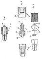
- FIGS. 1 and 4 an embodiment of a cannula holder according to the invention is shown, which is designated 10 and 18 and has its final non-wiederkonnektierbare form. While the first embodiment with protective cap 13 is in three parts, the second embodiment of the cannula holder according to the invention with protective cap 13 consists of four parts. The protective cap 13 is of no particular importance according to the invention. At the right end of the connection is 17 or 25 for a hose, not shown. The left-side end of the needle holder 10 or 18 is formed by the protective cap 13, which acts as a flow stop. In about the middle of the corrugated cap sleeve 11 and 20 is arranged. The size ratios of the individual components, which are explained in more detail below, are common, as is the plastic material, which can be selected for example from ABS, polycarbonate, polyethylene or polyamide. Other materials are conceivable for the person skilled in the art.
- the teeth 15 connected to the thread 19 in the inventive Luer-Lock connection 12, via which a cap sleeve or nut 11 is placed, which is rotatable about the shaft, but can not be deducted from the latter.
- a matching toothing 15 matching counter-toothing 22 is provided inside the outside grooved designed cap sleeve 11.
- the teeth 15 and 22 engage in a first direction of rotation locking each other while they slide freely in opposite direction of rotation to each other. The latter is accomplished via continuous and edgeless sloping flanks, which merge into a base.
- the cap sleeve 11 can not be removed from the rear shaft 23, since a circumferential latching projection 16 is provided in its end region.
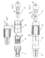
- the lock thread 19 is fixedly connected to and integrally formed with the Luer cone 27 and the rear shaft 23, in the second embodiment, the lock thread 19 is provided in a separate configuration and on the rear shaft 23 the Luer lock positive fitting 21 freely rotatably mounted. Also in this embodiment, the teeth 15 on the lock thread 19 cooperate with the counter-toothing 22 in the union nut 20 in the same manner as was the case in the first embodiment.
- the snap lock guarantees that the lock thread 19 after mounting on the connector 21 is not more of this can be deducted. This prevents that the cannula holder 18 can be disconnected again, because the rotatable lock thread is permanently connected by means of snap closure to the connector 21.
- An advantage over the first embodiment is the fact that the connector 21 does not rotate during tightening, thereby preventing the transmission tube, not shown, from twisting in the axial direction upon connection of the device and possibly causing it to bend and thus a patient risk can come.
Abstract
Description
Die Erfindung betrifft ein Luer-Lock positiv Anschlussstück nach dem Oberbegriff des Anspruches 1, sowie einen Kanülenhalter oder Katheter, der das Luer-Lock positiv Anschlussstück besitzt.The invention relates to a Luer lock positive fitting according to the preamble of claim 1, and a needle holder or catheter, which has the Luer lock positive fitting.
Derartige Luer-Lock positiv (männliche) Anschlussstücke bzw. Adapter nach DIN EN 1707 sind in den unterschiedlichsten Ausführungsformen bekannt. Üblicherweise sind diese wieder lösbar.Such Luer-Lock positive (male) fittings or adapters according to DIN EN 1707 are known in a variety of embodiments. Usually these are solvable again.
Aus der
Die
Gerade bei der Verabreichung von toxischen und generell für die Umwelt gefährlichen Medien, wie z.B. Zytostatika, ist es jedoch wünschenswert, jegliches Entkonnektieren der Luer-Lock-Verbindung, ob beabsichtigt oder unbeabsichtigt, sicher zu verhindern, damit weder Patienten, noch Personal mit dem gefährlichen Medium in Berührung kommen, welches durch gelöste Verbindungen austreten kann. Insofern besteht also Bedarf an einem positiven Luer-Lock Adapter bzw. Anschlussstück, das ein beabsichtigtes oder unbeabsichtigtes Entkonnektieren der Verbindung wirksam vermeidet und jegliche Gefährdungssituation ausschließt.However, especially with the administration of toxic and generally environmentally hazardous media, such as cytostatics, it is desirable to safely prevent any disconnection of the luer-lock compound, whether intentionally or unintentionally, so that neither patients nor personnel are exposed to the dangerous Medium come into contact, which can escape through dissolved compounds. In this respect, there is therefore a need for a positive Luer-Lock adapter or connecting piece, which effectively prevents an intentional or unintentional disconnection of the connection and excludes any danger situation.
Diese Aufgabe wird erfindungsgemäß dadurch gelöst bzw. das Problem dadurch beseitigt, dass es eine mit dem Lock-Gewinde wirksam verbundene Verzahnung aufweist und dass eine Überwurfhülse unlösbar und um den Schaft drehbar auf diesen aufgesetzt ist, die in ihrem Inneren eine passgerecht zu der Verzahnung ausgebildete Gegenverzahnung aufweist, wobei die Verzahnung und die Gegenverzahnung so ausgebildet sind, dass sie in einer ersten Drehrichtung zum Verriegeln der Luer-Lock-Verbindung der Überwurfhülse auf dem Schaft arretierend ineinander greifen, in einer zweiten, der ersten Drehrichtung entgegen gesetzten Drehrichtung jedoch freilaufend aneinander abgleiten, und dass an dem rückwärtigen Schaft (23) und/oder der Überwurfhülse (20) Rastmittel (16) zum unlösbaren Verrasten der Überwurfhülse (20) auf dem rückwärtigen Schaft (23) angeordnet sind.This object is achieved by the problem or eliminated in that it has an effectively connected to the lock thread teeth and that a cap sleeve is undetachable and rotatably mounted on the shaft on this, which formed in its interior a fitting to the toothing Has counter-toothing, wherein the toothing and the counter-toothing are formed so that they engage in a first rotational direction for locking the Luer-lock connection of the cap sleeve on the shaft locking into each other, however, in a second, the first rotational direction opposite direction of rotation but freely slide together in that latching means (16) for non-releasably latching the cap sleeve (20) on the rear shaft (23) are arranged on the rear shaft (23) and / or the cap sleeve (20).
Erfindungsgemäß gewährleistet die spezielle geometrische Kontur des Anschlussstückes, dass eine sichere flüssigkeits- und/oder gasdichte Verbindung permanent vorhanden bleibt und eine Entkonnektierung ausgeschlossen werden kann. Die erfindungsgemäß vorgesehene Verzahnung am Lock-Gewinde und die Gegenverzahnung im Inneren der Überwurfhülse ermöglichen ein Festziehen des Anschlussstücks durch beispielsweise Rechtsdrehung, wobei ein Losdrehen in entgegen gesetzter Drehrichtung durch Freilauf von Verzahnung und Gegenverzahnung verhindert wird.According to the invention, the special geometric contour of the connecting piece ensures that a secure liquid-tight and / or gas-tight connection remains permanently present and disconnection can be ruled out. The inventively provided teeth on the lock thread and the counter teeth in the interior of the cap sleeve allow tightening of the connector by, for example, clockwise rotation, with a loosening in the opposite direction of rotation is prevented by freewheeling of teeth and counter teeth.
Die Erfindung richtet sich ebenfalls auf einen Kanülenhalter oder Katheter, der das erfindungsgemäß ausgebildete Luer-Lock positiv Anschlussstück besitzt.The invention is also directed to a cannula holder or catheter having the inventively designed Luer-Lock positive fitting.
Weitere Vorteile und Merkmale gehen aus den Unteransprüchen 2 bis 6 hervor, die auch gemeinsam mit dem Hauptanspruch von erfinderischer Bedeutung sein können.Further advantages and features will become apparent from the dependent claims 2 to 6, which may also be together with the main claim of inventive importance.
Im Folgenden werden zwei bevorzugte Ausführungsbeispiele anhand der Figuren näher erläutert, auf die die Erfindung jedoch nicht beschränkt ist. Sie dienen lediglich dem besseren Verständnis der Erfindung und ihrer Funktionen. Es zeigt:
- Fig. 1
- eine Seitenansicht eines erfindungsgemäßen, zusammengesetzten Kanülenhalters mit Schutzkappe;
- Fig. 2
- eine schematische, dreiteilige Querschnittsansicht in Form einer Explosionsdarstellung der Einzelbestandteile des in
Fig. 1 gezeigten erfindungsgemäßen Kanülenhalters; - Fig. 3
- Seitenansichten zu den in
Fig. 2 gezeigten Querschnittsansichten der Einzelbestandteile; - Fig. 4
- eine Seitenansicht einer weiteren Ausführungsform eines erfindungsgemäßen, zusammengesetzten Kanülenhalters mit Schutzkappe;
- Fig. 5
- schematische Querschnittsansichten in Explosionsform des in
Fig. 4 gezeigten Kanülenhalters mit seinen Einzelbestandteilen ; und - Fig. 6
- Seitenansichten der in
Fig. 5 gezeigten Einzelbestandteile des Kanülenhalters.
- Fig. 1
- a side view of an inventive, composite needle holder with protective cap;
- Fig. 2
- a schematic, three-part cross-sectional view in the form of an exploded view of the individual components of in
Fig. 1 shown cannula holder according to the invention; - Fig. 3
- Side views to the in
Fig. 2 shown cross-sectional views of the individual components; - Fig. 4
- a side view of another embodiment of an inventive, composite cannula holder with protective cap;
- Fig. 5
- schematic cross-sectional views in exploded form of in
Fig. 4 shown cannula holder with its individual components; and - Fig. 6
- Side views of in
Fig. 5 shown individual components of the needle holder.
In den
Nachfolgend soll auf den besonderen Aufbau des Luer-Lock positiv Anschlussstücks 12 bzw. Luer Anschlussstückes 21 anhand der
Von besonderer erfindungsgemäßer Bedeutung für die erste Ausführungsform, die in den
Unter Bezugnahme auf die
Claims (8)
- Positive Luer Lock connector for connecting to all standard-conforming, negative Luer Lock connections with a Luer cone (27), a rear shank (23) connected to the Luer cone (27) and a lock thread (19), a toothing (15) actively connected to the lock thread (19) and a bush (11, 20) which is non-detachable and mounted in rotary manner about the shank (23) and which has in its interior a countertoothing (22) constructed in precise fitting manner with respect to the toothing (15), the toothing (15) and countertoothing (22) being so constructed that in a first rotation direction they engage in one another in arresting manner for locking the Luer Lock connection of the bush (11, 20) on shank (23) and in a second rotation direction opposite to the first rotation direction they slide in free-running manner on one another, characterized in that on the rear shank (23) and/or the bush (20) are provided detent means (16) for the non-detachable fixing of the bush (20) to the rear shank (23).
- Positive Luer Lock connector according to claim 1, characterized in that the toothing (25) and countertoothing (22) have oppositely directed contact surfaces, which pass rearwardly in each case via continuously and edgeless sloping flanks into a base surface.
- Positive Luer Lock connector according to claim 1, characterized in that the toothing (15) is applied to a surface positioned transversely to a longitudinal axis of the rear shank (23) and rearwards with respect to the toothing (15) and the countertoothing (22) is applied to an end face located within the bush (11, 20).
- Positive Luer Lock connector according to one of the claims 1 to 3, characterized in that the lock thread (19) is firmly connected to the Luer cone (27) and/or the rear shank (23) and is preferably integrally constructed therewith.
- Positive Luer Lock connector according to one of the claims 1 to 3, characterized in that the lock thread (19) is formed in a separate bush (20) mounted on the rear shank (23) so as to be freely rotatable about the same.
- Positive Luer Lock connector according to one of the preceding claims, characterized in that it is made from plastic, particularly ABS or polycarbonate.
- Cannula holder or catheter for use in the administration of cytostatics or other toxic media which are generally harmful to the environment to patients with a positive Luer Lock connector (12, 21) according to one of the preceding claims at its one end and with a connection (17, 25) for a transfer hose at its other end.
- Cannula holder or catheter according to claim 7, characterized in that it has a protective cap (13) mounted on the Luer cone (27) of the positive Luer Lock connector (12, 21).
Priority Applications (9)
| Application Number | Priority Date | Filing Date | Title |
|---|---|---|---|
| DE502006002902T DE502006002902D1 (en) | 2006-10-31 | 2006-10-31 | Non-reconnectable positive Luer-Lock connector |
| ES06022700T ES2322493T3 (en) | 2006-10-31 | 2006-10-31 | POSITIVE LUER-LOCK CONNECTION THAT IS NOT DISCONNECTABLE. |
| EP06022700A EP1917996B1 (en) | 2006-10-31 | 2006-10-31 | Luer Lock connector which is not disconnectable |
| AT06022700T ATE422937T1 (en) | 2006-10-31 | 2006-10-31 | NON-RECONNECTABLE POSITIVE LUER-LOCK CONNECTOR |
| PT06022700T PT1917996E (en) | 2006-10-31 | 2006-10-31 | Luer lock connector which is not disconnectable |
| CA2606834A CA2606834C (en) | 2006-10-31 | 2007-10-16 | Non-disconnectable positive luer-lock connector |
| AU2007229375A AU2007229375B2 (en) | 2006-10-31 | 2007-10-18 | Non-disconnectable positive Luer-lock connector |
| NZ562659A NZ562659A (en) | 2006-10-31 | 2007-10-18 | Non-disconnectable positive luer-lock connector |
| US11/924,818 US20080103485A1 (en) | 2006-10-31 | 2007-10-26 | Non-disconnectable positive luer-lock connector |
Applications Claiming Priority (1)
| Application Number | Priority Date | Filing Date | Title |
|---|---|---|---|
| EP06022700A EP1917996B1 (en) | 2006-10-31 | 2006-10-31 | Luer Lock connector which is not disconnectable |
Publications (2)
| Publication Number | Publication Date |
|---|---|
| EP1917996A1 EP1917996A1 (en) | 2008-05-07 |
| EP1917996B1 true EP1917996B1 (en) | 2009-02-18 |
Family
ID=37497895
Family Applications (1)
| Application Number | Title | Priority Date | Filing Date |
|---|---|---|---|
| EP06022700A Active EP1917996B1 (en) | 2006-10-31 | 2006-10-31 | Luer Lock connector which is not disconnectable |
Country Status (9)
| Country | Link |
|---|---|
| US (1) | US20080103485A1 (en) |
| EP (1) | EP1917996B1 (en) |
| AT (1) | ATE422937T1 (en) |
| AU (1) | AU2007229375B2 (en) |
| CA (1) | CA2606834C (en) |
| DE (1) | DE502006002902D1 (en) |
| ES (1) | ES2322493T3 (en) |
| NZ (1) | NZ562659A (en) |
| PT (1) | PT1917996E (en) |
Cited By (5)
| Publication number | Priority date | Publication date | Assignee | Title |
|---|---|---|---|---|
| US9114242B2 (en) | 2005-07-06 | 2015-08-25 | Icu Medical, Inc. | Medical connector |
| WO2018210498A1 (en) | 2017-05-18 | 2018-11-22 | Fresenius Kabi Deutschland Gmbh | Non-releasable connector device |
| EP3530312A1 (en) | 2018-02-21 | 2019-08-28 | Codan Holding GmbH | Securable connector with sleeve which cannot be disconnected |
| DE102021129674A1 (en) | 2021-11-15 | 2023-05-17 | B. Braun Melsungen Aktiengesellschaft | Connector with twist and shift protection |
| DE102022208343A1 (en) | 2022-08-11 | 2024-02-22 | B. Braun Melsungen Aktiengesellschaft | Medical fluid connector system |
Families Citing this family (55)
| Publication number | Priority date | Publication date | Assignee | Title |
|---|---|---|---|---|
| US8562583B2 (en) | 2002-03-26 | 2013-10-22 | Carmel Pharma Ab | Method and assembly for fluid transfer and drug containment in an infusion system |
| US7867215B2 (en) * | 2002-04-17 | 2011-01-11 | Carmel Pharma Ab | Method and device for fluid transfer in an infusion system |
| SE523001C2 (en) * | 2002-07-09 | 2004-03-23 | Carmel Pharma Ab | Coupling component for transmitting medical substances, comprises connecting mechanism for releasable connection to second coupling component having further channel for creating coupling, where connecting mechanism is thread |
| WO2004064903A1 (en) * | 2003-01-21 | 2004-08-05 | Carmel Pharma Ab | A needle for penetrating a membrane |
| WO2005041846A2 (en) | 2003-10-30 | 2005-05-12 | Teva Medical Ltd. | Safety drug handling device |
| HK1077154A2 (en) | 2003-12-30 | 2006-02-03 | Vasogen Ireland Ltd | Valve assembly |
| US7803139B2 (en) | 2005-07-06 | 2010-09-28 | Icu Medical, Inc. | Medical connector with closeable male luer |
| US7942860B2 (en) * | 2007-03-16 | 2011-05-17 | Carmel Pharma Ab | Piercing member protection device |
| US7975733B2 (en) * | 2007-05-08 | 2011-07-12 | Carmel Pharma Ab | Fluid transfer device |
| US8029747B2 (en) | 2007-06-13 | 2011-10-04 | Carmel Pharma Ab | Pressure equalizing device, receptacle and method |
| US8657803B2 (en) | 2007-06-13 | 2014-02-25 | Carmel Pharma Ab | Device for providing fluid to a receptacle |
| US8622985B2 (en) * | 2007-06-13 | 2014-01-07 | Carmel Pharma Ab | Arrangement for use with a medical device |
| US10398834B2 (en) * | 2007-08-30 | 2019-09-03 | Carmel Pharma Ab | Device, sealing member and fluid container |
| US8287513B2 (en) | 2007-09-11 | 2012-10-16 | Carmel Pharma Ab | Piercing member protection device |
| WO2009038505A1 (en) | 2007-09-17 | 2009-03-26 | Carmel Pharma Ab | Bag connector |
| NZ589151A (en) | 2008-05-14 | 2012-08-31 | J & J Solutions Inc | Systems and methods for safe medicament transport |
| US8075550B2 (en) * | 2008-07-01 | 2011-12-13 | Carmel Pharma Ab | Piercing member protection device |
| US9078992B2 (en) | 2008-10-27 | 2015-07-14 | Pursuit Vascular, Inc. | Medical device for applying antimicrobial to proximal end of catheter |
| US8523838B2 (en) * | 2008-12-15 | 2013-09-03 | Carmel Pharma Ab | Connector device |
| US8790330B2 (en) * | 2008-12-15 | 2014-07-29 | Carmel Pharma Ab | Connection arrangement and method for connecting a medical device to the improved connection arrangement |
| US8679090B2 (en) | 2008-12-19 | 2014-03-25 | Icu Medical, Inc. | Medical connector with closeable luer connector |
| US9168366B2 (en) | 2008-12-19 | 2015-10-27 | Icu Medical, Inc. | Medical connector with closeable luer connector |
| FR2944974B1 (en) * | 2009-04-29 | 2012-12-14 | Ace Dev Solution | DEVICE FOR CONNECTING BETWEEN A FIRST AND A SECOND TUBE FOR CONDUCTING A PRODUCT TO BE ADMINISTERED TO A PERSON |
| US8480646B2 (en) * | 2009-11-20 | 2013-07-09 | Carmel Pharma Ab | Medical device connector |
| USD637713S1 (en) | 2009-11-20 | 2011-05-10 | Carmel Pharma Ab | Medical device adaptor |
| EP2554152A4 (en) * | 2010-03-30 | 2015-09-23 | Terumo Corp | Connector and connector assembly |
| JP6058530B2 (en) | 2010-05-06 | 2017-01-11 | アイシーユー・メディカル・インコーポレーテッド | Medical connectors including sealable luer connectors |
| US8162013B2 (en) | 2010-05-21 | 2012-04-24 | Tobias Rosenquist | Connectors for fluid containers |
| US9168203B2 (en) | 2010-05-21 | 2015-10-27 | Carmel Pharma Ab | Connectors for fluid containers |
| NZ726167A (en) | 2010-05-27 | 2018-06-29 | J&J Solutions Inc | Closed fluid transfer system |
| US11628267B2 (en) | 2010-08-04 | 2023-04-18 | Medline Industries, Lp | Universal medical gas delivery system |
| WO2012162259A2 (en) | 2011-05-20 | 2012-11-29 | Excelsior Medical Corporation | Caps for cannula access devices |
| ES2797649T3 (en) | 2011-07-12 | 2020-12-03 | Icu Medical Inc | Device for the delivery of antimicrobial agent in a transdermal catheter |
| EP3760275A1 (en) | 2011-09-09 | 2021-01-06 | ICU Medical, Inc. | Medical connectors with fluid-resistant mating interfaces |
| US10098816B2 (en) | 2013-05-16 | 2018-10-16 | Becton Dickinson and Company Ltd. | Mechanical friction enhancement for threaded connection incorporating micro-threads |
| US9968771B2 (en) | 2013-05-16 | 2018-05-15 | Becton Dickinson and Company Limited | Mechanical friction enhancement for threaded connection incorporating crushable ribs |
| US9895290B2 (en) | 2013-05-16 | 2018-02-20 | Becton Dickinson and Company Ltd. | Mechanical friction enhancement for threaded connection incorporating opposing barb |
| CA2920199C (en) | 2013-08-02 | 2018-06-12 | J&J SOLUTIONS, INC. d.b.a CORVIDA MEDICAL | Compounding systems and methods for safe medicament transport |
| US10046156B2 (en) | 2014-05-02 | 2018-08-14 | Excelsior Medical Corporation | Strip package for antiseptic cap |
| WO2016182822A1 (en) | 2015-05-08 | 2016-11-17 | Icu Medical, Inc. | Medical connectors configured to receive emitters of therapeutic agents |
| WO2016189538A1 (en) * | 2015-05-28 | 2016-12-01 | Elcam Medical Agricultural Cooperative Association Ltd. | Rotating connector |
| JP6895142B2 (en) | 2015-09-17 | 2021-06-30 | ジェイ アンド ジェイ ソリューションズ,インコーポレイテッド | Drug vial assembly |
| WO2017066406A1 (en) | 2015-10-13 | 2017-04-20 | J&J SOLUTIONS, INC. d/b/a Corvida Medical | Automated compounding equipment for closed fluid transfer system |
| US10022531B2 (en) | 2016-01-21 | 2018-07-17 | Teva Medical Ltd. | Luer lock adaptor |
| DK3525865T3 (en) | 2016-10-14 | 2022-10-24 | Icu Medical Inc | Disinfectant caps for medical connectors |
| WO2018204206A2 (en) | 2017-05-01 | 2018-11-08 | Icu Medical, Inc. | Medical fluid connectors and methods for providing additives in medical fluid lines |
| US11541220B2 (en) | 2018-11-07 | 2023-01-03 | Icu Medical, Inc. | Needleless connector with antimicrobial properties |
| US11534595B2 (en) | 2018-11-07 | 2022-12-27 | Icu Medical, Inc. | Device for delivering an antimicrobial composition into an infusion device |
| US11517732B2 (en) | 2018-11-07 | 2022-12-06 | Icu Medical, Inc. | Syringe with antimicrobial properties |
| US11541221B2 (en) | 2018-11-07 | 2023-01-03 | Icu Medical, Inc. | Tubing set with antimicrobial properties |
| US11400195B2 (en) | 2018-11-07 | 2022-08-02 | Icu Medical, Inc. | Peritoneal dialysis transfer set with antimicrobial properties |
| EP3883638A1 (en) | 2018-11-21 | 2021-09-29 | ICU Medical, Inc. | Antimicrobial device comprising a cap with ring and insert |
| US20210178143A1 (en) * | 2019-12-16 | 2021-06-17 | Codan Holding Gmbh | Nondisconnectable, securable connector having a capping sleeve |
| AU2020200043B1 (en) * | 2020-01-03 | 2021-04-08 | Codan Holding Gmbh | Nondisconnectable, securable connector having a capping sleeve |
| EP4255552A1 (en) | 2020-12-07 | 2023-10-11 | ICU Medical, Inc. | Peritoneal dialysis caps, systems and methods |
Family Cites Families (13)
| Publication number | Priority date | Publication date | Assignee | Title |
|---|---|---|---|---|
| US242564A (en) * | 1881-06-07 | Hose-coupling | ||
| US2204392A (en) * | 1938-02-25 | 1940-06-11 | Mary Mastowski | Hose and pipe coupler |
| US3722727A (en) * | 1971-04-16 | 1973-03-27 | Sunbeam Plastics Corp | Safety closure for a medicine bottle |
| US4452473A (en) * | 1982-07-26 | 1984-06-05 | Baxter Travenol Laboratories, Inc. | Luer connection system |
| US5000332A (en) * | 1989-06-05 | 1991-03-19 | Whitacre Robert J | Waste disposal container with a non-removable, permanent closure |
| US5217130A (en) * | 1991-02-25 | 1993-06-08 | Primary Delivery Systems, Inc. | Child resistant cap with biased keyway |
| FR2710715B1 (en) * | 1993-09-29 | 1996-09-20 | Marc Jean Pierre | Self-locking lock for pipes. |
| US5498043A (en) * | 1995-01-25 | 1996-03-12 | Plastic Specialties And Technologies, Inc. | Hose fitting having ferrule anti-rotation ratchet teeth |
| US5620427A (en) * | 1995-04-27 | 1997-04-15 | David R. Kipp | Luer lock system |
| GB9801261D0 (en) * | 1998-01-21 | 1998-03-18 | Peters Joseph L | Couplings for medical cannulae |
| DE20109061U1 (en) * | 2001-05-31 | 2001-08-09 | Braun Melsungen Ag | Patient safety connector |
| US7497484B2 (en) * | 2004-08-11 | 2009-03-03 | Smiths Medical Asd, Inc. | Medical coupling system |
| US7347458B2 (en) * | 2005-01-14 | 2008-03-25 | C. R. Bard, Inc. | Locking luer fitting |
-
2006
- 2006-10-31 PT PT06022700T patent/PT1917996E/en unknown
- 2006-10-31 ES ES06022700T patent/ES2322493T3/en active Active
- 2006-10-31 AT AT06022700T patent/ATE422937T1/en active
- 2006-10-31 DE DE502006002902T patent/DE502006002902D1/en active Active
- 2006-10-31 EP EP06022700A patent/EP1917996B1/en active Active
-
2007
- 2007-10-16 CA CA2606834A patent/CA2606834C/en active Active
- 2007-10-18 AU AU2007229375A patent/AU2007229375B2/en active Active
- 2007-10-18 NZ NZ562659A patent/NZ562659A/en unknown
- 2007-10-26 US US11/924,818 patent/US20080103485A1/en not_active Abandoned
Cited By (8)
| Publication number | Priority date | Publication date | Assignee | Title |
|---|---|---|---|---|
| US9114242B2 (en) | 2005-07-06 | 2015-08-25 | Icu Medical, Inc. | Medical connector |
| US9126028B2 (en) | 2005-07-06 | 2015-09-08 | Icu Medical, Inc. | Medical connector |
| US9126029B2 (en) | 2005-07-06 | 2015-09-08 | Icu Medical, Inc. | Medical connector |
| WO2018210498A1 (en) | 2017-05-18 | 2018-11-22 | Fresenius Kabi Deutschland Gmbh | Non-releasable connector device |
| EP3530312A1 (en) | 2018-02-21 | 2019-08-28 | Codan Holding GmbH | Securable connector with sleeve which cannot be disconnected |
| DE102021129674A1 (en) | 2021-11-15 | 2023-05-17 | B. Braun Melsungen Aktiengesellschaft | Connector with twist and shift protection |
| WO2023084009A1 (en) | 2021-11-15 | 2023-05-19 | B. Braun Melsungen Ag | Connector comprising an anti-rotation and anti-displacement means |
| DE102022208343A1 (en) | 2022-08-11 | 2024-02-22 | B. Braun Melsungen Aktiengesellschaft | Medical fluid connector system |
Also Published As
| Publication number | Publication date |
|---|---|
| ES2322493T3 (en) | 2009-06-22 |
| DE502006002902D1 (en) | 2009-04-02 |
| EP1917996A1 (en) | 2008-05-07 |
| AU2007229375A1 (en) | 2008-05-15 |
| US20080103485A1 (en) | 2008-05-01 |
| CA2606834A1 (en) | 2008-04-30 |
| CA2606834C (en) | 2015-11-24 |
| AU2007229375B2 (en) | 2012-07-12 |
| ATE422937T1 (en) | 2009-03-15 |
| PT1917996E (en) | 2009-05-15 |
| NZ562659A (en) | 2008-07-31 |
Similar Documents
| Publication | Publication Date | Title |
|---|---|---|
| EP1917996B1 (en) | Luer Lock connector which is not disconnectable | |
| DE60106720T2 (en) | Luer connection for medical fluid lines | |
| DE602006000689T2 (en) | Medical coupling with locking device | |
| DE69932918T2 (en) | Coupling for medical cannulas | |
| DE4129397C1 (en) | ||
| DE2840728C2 (en) | RF coaxial connector | |
| EP1537829B1 (en) | Medical device comprising instrument insert and means for blocking the movement of the handle | |
| DE2356093C2 (en) | Screw-on hose coupling | |
| DE2926352A1 (en) | CONNECTING DEVICE FOR LINES | |
| EP2008607A1 (en) | Coupling device for fixing medical instruments to a holding device | |
| DE102007003507A1 (en) | Locking device for plug connection unit | |
| EP0633037A1 (en) | Connection system for the joining of fluid containers | |
| WO2002096500A1 (en) | Patient safety connector | |
| DE102014209731A1 (en) | Steering and motor vehicle | |
| EP1900337B1 (en) | Medical or dental tool holder with a front and rear tool holder apron | |
| EP3244962B1 (en) | Connection device for a medical fluid conduit system | |
| EP3293436A1 (en) | Coupling device for connecting with a lubricating nipple | |
| WO2013020637A2 (en) | Connecting device for connecting a fluid line | |
| EP3310426B1 (en) | Male and female luer connector and luer connection system | |
| EP1264127A1 (en) | ROTATABLE STOPCOCK FOR A MALE COUPLING HAVING A 90o OFFSET CONNECTING PIECE | |
| EP1378207B1 (en) | Medical or dental handpiece with a push-button for releasing a tool | |
| EP3530312B1 (en) | Securable connector with sleeve which cannot be disconnected | |
| DE102012214718A1 (en) | syringe | |
| EP2369215B1 (en) | Connector | |
| EP2808052B1 (en) | Coupling device for connecting hoses, in particular dental supply hoses |
Legal Events
| Date | Code | Title | Description |
|---|---|---|---|
| PUAI | Public reference made under article 153(3) epc to a published international application that has entered the european phase |
Free format text: ORIGINAL CODE: 0009012 |
|
| 17P | Request for examination filed |
Effective date: 20070523 |
|
| AK | Designated contracting states |
Kind code of ref document: A1 Designated state(s): AT BE BG CH CY CZ DE DK EE ES FI FR GB GR HU IE IS IT LI LT LU LV MC NL PL PT RO SE SI SK TR |
|
| AX | Request for extension of the european patent |
Extension state: AL BA HR MK RS |
|
| GRAP | Despatch of communication of intention to grant a patent |
Free format text: ORIGINAL CODE: EPIDOSNIGR1 |
|
| GRAS | Grant fee paid |
Free format text: ORIGINAL CODE: EPIDOSNIGR3 |
|
| AKX | Designation fees paid |
Designated state(s): AT BE BG CH CY CZ DE DK EE ES FI FR GB GR HU IE IS IT LI LT LU LV MC NL PL PT RO SE SI SK TR |
|
| GRAA | (expected) grant |
Free format text: ORIGINAL CODE: 0009210 |
|
| AK | Designated contracting states |
Kind code of ref document: B1 Designated state(s): AT BE BG CH CY CZ DE DK EE ES FI FR GB GR HU IE IS IT LI LT LU LV MC NL PL PT RO SE SI SK TR |
|
| REG | Reference to a national code |
Ref country code: GB Ref legal event code: FG4D Free format text: NOT ENGLISH |
|
| REG | Reference to a national code |
Ref country code: CH Ref legal event code: EP |
|
| REG | Reference to a national code |
Ref country code: IE Ref legal event code: FG4D Free format text: LANGUAGE OF EP DOCUMENT: GERMAN |
|
| REF | Corresponds to: |
Ref document number: 502006002902 Country of ref document: DE Date of ref document: 20090402 Kind code of ref document: P |
|
| REG | Reference to a national code |
Ref country code: PT Ref legal event code: SC4A Free format text: AVAILABILITY OF NATIONAL TRANSLATION Effective date: 20090511 |
|
| REG | Reference to a national code |
Ref country code: SE Ref legal event code: TRGR |
|
| REG | Reference to a national code |
Ref country code: ES Ref legal event code: FG2A Ref document number: 2322493 Country of ref document: ES Kind code of ref document: T3 |
|
| PG25 | Lapsed in a contracting state [announced via postgrant information from national office to epo] |
Ref country code: LT Free format text: LAPSE BECAUSE OF FAILURE TO SUBMIT A TRANSLATION OF THE DESCRIPTION OR TO PAY THE FEE WITHIN THE PRESCRIBED TIME-LIMIT Effective date: 20090218 Ref country code: FI Free format text: LAPSE BECAUSE OF FAILURE TO SUBMIT A TRANSLATION OF THE DESCRIPTION OR TO PAY THE FEE WITHIN THE PRESCRIBED TIME-LIMIT Effective date: 20090218 Ref country code: SI Free format text: LAPSE BECAUSE OF FAILURE TO SUBMIT A TRANSLATION OF THE DESCRIPTION OR TO PAY THE FEE WITHIN THE PRESCRIBED TIME-LIMIT Effective date: 20090218 |
|
| PG25 | Lapsed in a contracting state [announced via postgrant information from national office to epo] |
Ref country code: LV Free format text: LAPSE BECAUSE OF FAILURE TO SUBMIT A TRANSLATION OF THE DESCRIPTION OR TO PAY THE FEE WITHIN THE PRESCRIBED TIME-LIMIT Effective date: 20090218 Ref country code: PL Free format text: LAPSE BECAUSE OF FAILURE TO SUBMIT A TRANSLATION OF THE DESCRIPTION OR TO PAY THE FEE WITHIN THE PRESCRIBED TIME-LIMIT Effective date: 20090218 Ref country code: IS Free format text: LAPSE BECAUSE OF FAILURE TO SUBMIT A TRANSLATION OF THE DESCRIPTION OR TO PAY THE FEE WITHIN THE PRESCRIBED TIME-LIMIT Effective date: 20090618 |
|
| REG | Reference to a national code |
Ref country code: IE Ref legal event code: FD4D |
|
| PG25 | Lapsed in a contracting state [announced via postgrant information from national office to epo] |
Ref country code: EE Free format text: LAPSE BECAUSE OF FAILURE TO SUBMIT A TRANSLATION OF THE DESCRIPTION OR TO PAY THE FEE WITHIN THE PRESCRIBED TIME-LIMIT Effective date: 20090218 Ref country code: IE Free format text: LAPSE BECAUSE OF FAILURE TO SUBMIT A TRANSLATION OF THE DESCRIPTION OR TO PAY THE FEE WITHIN THE PRESCRIBED TIME-LIMIT Effective date: 20090218 Ref country code: CZ Free format text: LAPSE BECAUSE OF FAILURE TO SUBMIT A TRANSLATION OF THE DESCRIPTION OR TO PAY THE FEE WITHIN THE PRESCRIBED TIME-LIMIT Effective date: 20090218 Ref country code: DK Free format text: LAPSE BECAUSE OF FAILURE TO SUBMIT A TRANSLATION OF THE DESCRIPTION OR TO PAY THE FEE WITHIN THE PRESCRIBED TIME-LIMIT Effective date: 20090218 |
|
| PG25 | Lapsed in a contracting state [announced via postgrant information from national office to epo] |
Ref country code: SK Free format text: LAPSE BECAUSE OF FAILURE TO SUBMIT A TRANSLATION OF THE DESCRIPTION OR TO PAY THE FEE WITHIN THE PRESCRIBED TIME-LIMIT Effective date: 20090218 Ref country code: RO Free format text: LAPSE BECAUSE OF FAILURE TO SUBMIT A TRANSLATION OF THE DESCRIPTION OR TO PAY THE FEE WITHIN THE PRESCRIBED TIME-LIMIT Effective date: 20090218 |
|
| PLBE | No opposition filed within time limit |
Free format text: ORIGINAL CODE: 0009261 |
|
| STAA | Information on the status of an ep patent application or granted ep patent |
Free format text: STATUS: NO OPPOSITION FILED WITHIN TIME LIMIT |
|
| 26N | No opposition filed |
Effective date: 20091119 |
|
| PG25 | Lapsed in a contracting state [announced via postgrant information from national office to epo] |
Ref country code: BG Free format text: LAPSE BECAUSE OF FAILURE TO SUBMIT A TRANSLATION OF THE DESCRIPTION OR TO PAY THE FEE WITHIN THE PRESCRIBED TIME-LIMIT Effective date: 20090518 |
|
| PG25 | Lapsed in a contracting state [announced via postgrant information from national office to epo] |
Ref country code: MC Free format text: LAPSE BECAUSE OF NON-PAYMENT OF DUE FEES Effective date: 20091031 |
|
| PG25 | Lapsed in a contracting state [announced via postgrant information from national office to epo] |
Ref country code: GR Free format text: LAPSE BECAUSE OF FAILURE TO SUBMIT A TRANSLATION OF THE DESCRIPTION OR TO PAY THE FEE WITHIN THE PRESCRIBED TIME-LIMIT Effective date: 20090519 |
|
| PG25 | Lapsed in a contracting state [announced via postgrant information from national office to epo] |
Ref country code: LU Free format text: LAPSE BECAUSE OF NON-PAYMENT OF DUE FEES Effective date: 20091031 |
|
| PG25 | Lapsed in a contracting state [announced via postgrant information from national office to epo] |
Ref country code: HU Free format text: LAPSE BECAUSE OF FAILURE TO SUBMIT A TRANSLATION OF THE DESCRIPTION OR TO PAY THE FEE WITHIN THE PRESCRIBED TIME-LIMIT Effective date: 20090819 |
|
| PG25 | Lapsed in a contracting state [announced via postgrant information from national office to epo] |
Ref country code: TR Free format text: LAPSE BECAUSE OF FAILURE TO SUBMIT A TRANSLATION OF THE DESCRIPTION OR TO PAY THE FEE WITHIN THE PRESCRIBED TIME-LIMIT Effective date: 20090218 |
|
| PG25 | Lapsed in a contracting state [announced via postgrant information from national office to epo] |
Ref country code: CY Free format text: LAPSE BECAUSE OF FAILURE TO SUBMIT A TRANSLATION OF THE DESCRIPTION OR TO PAY THE FEE WITHIN THE PRESCRIBED TIME-LIMIT Effective date: 20090218 |
|
| REG | Reference to a national code |
Ref country code: FR Ref legal event code: PLFP Year of fee payment: 10 |
|
| REG | Reference to a national code |
Ref country code: FR Ref legal event code: PLFP Year of fee payment: 11 |
|
| REG | Reference to a national code |
Ref country code: FR Ref legal event code: PLFP Year of fee payment: 12 |
|
| REG | Reference to a national code |
Ref country code: FR Ref legal event code: PLFP Year of fee payment: 13 |
|
| PGFP | Annual fee paid to national office [announced via postgrant information from national office to epo] |
Ref country code: BE Payment date: 20221020 Year of fee payment: 17 |
|
| REG | Reference to a national code |
Ref country code: DE Ref legal event code: R081 Ref document number: 502006002902 Country of ref document: DE Owner name: CODAN MEDIZINISCHE GERAETE GMBH, DE Free format text: FORMER OWNER: CODAN HOLDING GMBH, 23738 LENSAHN, DE |
|
| PGFP | Annual fee paid to national office [announced via postgrant information from national office to epo] |
Ref country code: NL Payment date: 20231023 Year of fee payment: 18 |
|
| PGFP | Annual fee paid to national office [announced via postgrant information from national office to epo] |
Ref country code: GB Payment date: 20231025 Year of fee payment: 18 |
|
| PGFP | Annual fee paid to national office [announced via postgrant information from national office to epo] |
Ref country code: ES Payment date: 20231117 Year of fee payment: 18 |
|
| PGFP | Annual fee paid to national office [announced via postgrant information from national office to epo] |
Ref country code: SE Payment date: 20231025 Year of fee payment: 18 Ref country code: PT Payment date: 20231024 Year of fee payment: 18 Ref country code: IT Payment date: 20231031 Year of fee payment: 18 Ref country code: FR Payment date: 20231023 Year of fee payment: 18 Ref country code: DE Payment date: 20230926 Year of fee payment: 18 Ref country code: CH Payment date: 20231102 Year of fee payment: 18 Ref country code: AT Payment date: 20231019 Year of fee payment: 18 |
|
| PGFP | Annual fee paid to national office [announced via postgrant information from national office to epo] |
Ref country code: BE Payment date: 20231023 Year of fee payment: 18 |