EP1911482A2 - Turbulent air cleaning method and apparatus for catheter assemblies - Google Patents
Turbulent air cleaning method and apparatus for catheter assemblies Download PDFInfo
- Publication number
- EP1911482A2 EP1911482A2 EP08000063A EP08000063A EP1911482A2 EP 1911482 A2 EP1911482 A2 EP 1911482A2 EP 08000063 A EP08000063 A EP 08000063A EP 08000063 A EP08000063 A EP 08000063A EP 1911482 A2 EP1911482 A2 EP 1911482A2
- Authority
- EP
- European Patent Office
- Prior art keywords
- catheter tube
- cover member
- cleaning
- tube
- orifice
- Prior art date
- Legal status (The legal status is an assumption and is not a legal conclusion. Google has not performed a legal analysis and makes no representation as to the accuracy of the status listed.)
- Granted
Links
Images


Classifications
-
- A—HUMAN NECESSITIES
- A61—MEDICAL OR VETERINARY SCIENCE; HYGIENE
- A61M—DEVICES FOR INTRODUCING MEDIA INTO, OR ONTO, THE BODY; DEVICES FOR TRANSDUCING BODY MEDIA OR FOR TAKING MEDIA FROM THE BODY; DEVICES FOR PRODUCING OR ENDING SLEEP OR STUPOR
- A61M25/00—Catheters; Hollow probes
-
- A—HUMAN NECESSITIES
- A61—MEDICAL OR VETERINARY SCIENCE; HYGIENE
- A61M—DEVICES FOR INTRODUCING MEDIA INTO, OR ONTO, THE BODY; DEVICES FOR TRANSDUCING BODY MEDIA OR FOR TAKING MEDIA FROM THE BODY; DEVICES FOR PRODUCING OR ENDING SLEEP OR STUPOR
- A61M16/00—Devices for influencing the respiratory system of patients by gas treatment, e.g. mouth-to-mouth respiration; Tracheal tubes
- A61M16/04—Tracheal tubes
- A61M16/0463—Tracheal tubes combined with suction tubes, catheters or the like; Outside connections
-
- A—HUMAN NECESSITIES
- A61—MEDICAL OR VETERINARY SCIENCE; HYGIENE
- A61M—DEVICES FOR INTRODUCING MEDIA INTO, OR ONTO, THE BODY; DEVICES FOR TRANSDUCING BODY MEDIA OR FOR TAKING MEDIA FROM THE BODY; DEVICES FOR PRODUCING OR ENDING SLEEP OR STUPOR
- A61M25/00—Catheters; Hollow probes
- A61M2025/0019—Cleaning catheters or the like, e.g. for reuse of the device, for avoiding replacement
Landscapes
- Health & Medical Sciences (AREA)
- Pulmonology (AREA)
- Life Sciences & Earth Sciences (AREA)
- Anesthesiology (AREA)
- General Health & Medical Sciences (AREA)
- Biomedical Technology (AREA)
- Heart & Thoracic Surgery (AREA)
- Hematology (AREA)
- Veterinary Medicine (AREA)
- Animal Behavior & Ethology (AREA)
- Engineering & Computer Science (AREA)
- Public Health (AREA)
- Emergency Medicine (AREA)
- Biophysics (AREA)
- Infusion, Injection, And Reservoir Apparatuses (AREA)
- External Artificial Organs (AREA)
- Cleaning In General (AREA)
- Respiratory Apparatuses And Protective Means (AREA)
- Cleaning By Liquid Or Steam (AREA)
Abstract
Description
- There are a number of different circumstances in which it is necessary for a person to have an artificial airway placed in his or her respiratory tract. As used herein, the phrase "artificial airway" includes devices such as tracheostomy tubes, endotracheal tubes, and the like. An artificial airway keeps the patient's natural airway open so that adequate lung ventilation can be maintained.
- In certain situations, the artificial airway must be left in the patient for a prolonged period of time. In these situations, it is critical that respiratory secretions be periodically removed from the patient's respiratory tract. This is typically accomplished by the use of a respiratory suction catheter.
- With conventional closed suction catheter assemblies, for example as set forth in
U.S. Patent Nos. 3,991,762 and4,569,344 , the catheter tube is enveloped by a protective sleeve. The catheter assembly includes a valve mechanism in communication with a vacuum source to control the suctioning process. At its distal or patient end, the closed suction catheter assembly is attached to the artificial airway via a manifold, connector, adaptor, or the like. When it is desired to remove secretions and mucous from the patient's respiratory tract, the catheter tube is advanced through the protective sleeve and into the patient's respiratory system through the artificial airway. Negative pressure is then applied to the proximal or clinician end of the catheter tube to evacuate the secretions and mucous. The tube is then withdrawn from the artificial airway and, as the catheter tube is pulled back into the protective sleeve, a wiper or seal strips or scrapes a substantial portion of any mucous or secretions from the outside of the catheter tube. However, the distal tip portion of the catheter tube does not pass through the seal or wiper and thus any secretions or mucous on the distal end must be removed by other means. - Some closed suction catheter assemblies typically include a lavage port for injecting a cleaning/lavage solution into a chamber at the distal end of the catheter assembly as suction is applied through the catheter tube for loosening and removing the secretions and mucous scraped from the exterior of the catheter tube. This procedure may be done with the catheter assembly attached to or removed from the artificial airway and the ventilation circuit.
- In certain situations, the lavage injection and suctioning process may not adequately remove the secretions and mucous adhering to the distal tip of the catheter tube and the clinician may repeat the cleaning process a number of times in an attempt to clean the catheter tip. If the mucous and secretions accumulate or dry on the catheter tip, they can interfere with the suction efficiency of the catheter and necessitate premature replacement of the entire closed suction catheter assembly.
- It may also be desired to remove any cleaning/lavage solution that may remain in the lavage chamber after the cleaning procedure before using the device again.
- Thus, there is a need for a suction catheter assembly having a more efficient mechanism and method for adequately cleaning a catheter tube of a suction catheter assembly.
- Objects and advantages of the invention will be set forth in part in the following description, or may be obvious from the description, or may be learned through practice of the invention.
- As used herein, the term "distal" refers to the direction of the patient and the term "proximal" refers to the direction of the clinician.
- The present invention relates to a method and apparatus for creating a turbulent fluid flow at an end of a tube having a distal opening and one or more side openings adjacent to the distal opening. It is believed that such a turbulent flow may have numerous beneficial applications in various fields in mixing procedures, cleaning procedures, etc. The invention has particular usefulness in the medical field. For example, in one particularly well suited application of the invention, the turbulent flow significantly enhances cleaning of the distal end portion of a suction catheter. It is also contemplated that the turbulent flow may be useful in other applications, including mixing, heating, or cooling solutions. It should thus be appreciated that the present method and apparatus are not limited to any particular type or configuration of medical device or intended use.
- The method includes disposing the distal end portion of the medical tube in a closed chamber having a first orifice defined therethrough. The orifice is disposed in the chamber so as to be generally opposite from the tube. A liquid, such as a lavage or cleaning solution, is introduced into the chamber. The liquid is drawn into the distal opening in the tube, for example by applying a suction through the tube. As the liquid is drawn into the distal opening, another fluid medium, such as air, is drawn into the chamber through the first orifice. Applicants believe that a flow pattern is established wherein the fluid medium is drawn through the orifice and into the distal opening in the tube with the liquid. A portion of the fluid/liquid mixture drawn into the tube is conveyed out the side opening(s) in the tube, and back into the distal opening in the tube. This flow pattern may create a turbulence in the lavage or cleaning solution within the chamber, particularly around the circumference of the tube and within the distal end portion of the tube. It has been found that this turbulence creates a significant advantage in cleaning the distal end portion of the tube. For example, in an embodiment wherein the medical tube is a suction catheter tube, the turbulent air flow assists in breaking up conglomerations of mucous and secretions which the lavage/cleaning solution alone may not.
- In the embodiment wherein the medical device tube is a catheter tube, particularly a suction catheter tube, the distal end portion of the tube may be withdrawn into a distal fitting such as an adaptor or manifold housing of the respective catheter assembly. "Fitting" is a relatively broad term used to encompass any structure located at the distal end of the catheter assembly through which the catheter tube is withdrawn and includes, for example, any configuration of adaptor, connector, manifold, extension, etc. The fitting thus defines at least in part a portion of the closed chamber. The closed chamber may be considered as a cleaning chamber.
- Once the distal end portion of the catheter tube is withdrawn into the fitting, a cover member is used to close off or seal the cleaning chamber. The first orifice may be defined through this cover member.
- In one embodiment, the fitting may comprise an adaptor having a port that is detachable from a patient's artificial airway, such as a tracheostomy tube, endotracheal tube, and the like. In this embodiment, the cover member may be a component separate from the adaptor that is configured to then be attached to the adaptor to close off the port once the distal end portion of the catheter tube has been withdrawn into the adaptor. The cover member cooperates with the adaptor to define the cleaning chamber in which the distal end portion of the catheter tube is disposed.
- In an alternate embodiment, the cover member may be connected to and disposed within the fitting, particularly in the adaptor embodiment of the invention. The catheter tube is withdrawn into the adaptor past the cover member which then moves automatically to a sealing position once the distal end of the catheter tube has passed the cover member. For example, in this embodiment, the cover member may comprise a hinged flap member that moves into a position generally opposite from the distal end of the catheter tube once the catheter tube has been withdrawn past the flap member.
- Once the distal end portion of the catheter tube is properly located within the cleaning chamber and the cover member has been positioned so that the first orifice is generally opposite from the distal opening in the tube, the turbulent flow process is initiated as described above. In the embodiment of the invention wherein the catheter tube is a respiratory suction catheter, suction is applied at the proximal end of the tube to draw the cleaning solution into the tube. This suction also establishes a vacuum condition within the cleaning chamber resulting in air being drawn through the first orifice into the cover member. In an alternate embodiment, the air introduced through the first orifice may be pressurized air.
- In a cleaning operation as described herein, it may be desired to remove any remaining cleaning solution from the cleaning chamber prior to reusing the respiratory suction catheter. The cleaning solution is typically removed by suctioning the solution from the chamber through the distal opening of the catheter tube. However, with relatively larger cleaning chambers, it is possible that not all of the cleaning solution may be removed. Accordingly, the method and apparatus according to the invention may include additional steps and structure to ensure adequate removal of the cleaning solution from the cleaning chamber.
- In one embodiment, additional orifices or holes are defined in the cleaning chamber and are disposed so as to direct the fluid medium, such as air, into the cleaning chamber at an angle and orientation so as to urge the lavage/cleaning solution away from the sides of the cleaning chamber and towards the distal opening in the catheter tube. After air is drawn through the first orifice for a period of time sufficient for cleaning the distal end portion of the catheter tube, the air or other fluid medium is then introduced through the additional orifices. In one embodiment, the additional orifices are a ring of orifices disposed around the first orifice. The additional orifices are covered by a separate cover device or cap.
- The invention will be described in greater detail below with reference to various embodiments depicted in the figures.
-
-
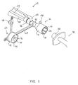
Figure 1 is a partial perspective view of a catheter assembly according to the present invention; -
Figure 2 is a cross-sectional view of the distal portion of the catheter assembly ofFig. 1 ; -
Figure 3 is a perspective view of a distal portion of another embodiment of a catheter assembly according to the present invention; -
Figure 4 is a cross-sectional operational view of the distal end of a catheter assembly according to the invention; -
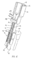
Figure 5 is a perspective and partial cross-sectional view of an alternate embodiment of a catheter assembly according to the invention; -
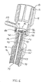
Figure 6 is an alternate cross-sectional view of the catheter assembly embodiment ofFig. 5 ; and -
Figure 7 is a perspective view of a cover member in accordance with the invention. - Reference will now be made in detail to embodiments of the invention, one or more examples of which are shown in the drawings. It should be appreciated that each example is provided by way of explaining the invention, and not as a limitation of the invention. For example, features illustrated or described with respect to one embodiment may be used with another embodiment to yield still a further embodiment. These and other modifications and variations are within the scope and spirit of the invention.
- The method and apparatus for creating turbulent flow conditions at the distal end of a tube will be described with reference to a medical device embodiment of the invention, particularly a catheter assembly embodiment depicted in the figures. It should be appreciated, however, that the method and apparatus of the present invention are not limited to the catheter assemblies shown, or the medical field in general. The method and apparatus may be utilized in any device wherein it is desired to create turbulent flow conditions for any number of reasons, including cleaning a tube or other device, mixing fluids, heating or cooling solutions, etc.
- Referring to
Figs. 1 and2 in particular, acatheter assembly 10 is illustrated, particularly a respiratory suction catheter assembly utilizing asuction catheter tube 34 having adistal end portion 36. Thedistal end portion 36 includes adistal opening 38 defined in an extremedistal tip 42 of the catheter tube and at least one lateral orside opening 40 disposed adjacent to thedistal tip 42. The use of a respiratory suction catheter to remove secretions and mucous from a patient's respiratory tract is well known by those skilled in the art and need not be explained in detail herein. The turbulent flow method and apparatus according to the present invention is particularly useful for cleaning accumulated secretions and mucous from thedistal end portion 36 of thecatheter tube 34 and, thus, the respiratory catheter suction assembly is useful for explaining the present invention. - A fitting 12 is provided at the distal end of the catheter assembly. The term "fitting" is used herein as a broad generic term that encompasses any structure provided at the distal end of the
catheter assembly 10 and may include, for example, anadaptor 14 as illustrated in the figures. Referring toFigs. 1 and2 , theadaptor 14 is particularly configured for connecting with a hub ormanifold 32 of a patient'sartificial airway 30. Theartificial airway 30 may be, for example, a tracheostomy tube, endotracheal tube, or the like. Theadaptor 14 includes aside wall 16 defining aport 20 that communicates with thehub 32 of theartificial airway 30.Radially projecting ribs 18 may be defined on the inner circumference of thewall 16 to ensure adequate airflow between thewall 16 and thehub 32. Theadaptor 14 may include one or moreadditional ports 28 for providing access through theadaptor 14 to the patient's respiratory tract. It should be appreciated that the particular configuration of theadaptor 14 illustrated in the figures is not a limiting feature of the invention. The adaptor may take on any desired form or configuration. - The
adaptor 14 configuration ofFigs. 1 ,2 , and4 is also described in detail in co-pending and commonly ownedU.S. Patent Application Serial No. 09/702,375 filed on October 31, 2000 - The
catheter assembly 10 may also include various configurations of thedistal structure 46 for interconnecting the components of thecatheter assembly 10. For example, referring toFig. 2 , thedistal end structure 46 may include aconnection member 47. A fitting 48 may be connected to the distal portion ofmember 47, the fitting 48 including alongitudinally extending collar 24 having an inner diameter slightly greater than the outer diameter of thecatheter tube 34 such that anannular space 26 is defined between the components, as particularly seen inFig. 2 . Awiper seal 25 may be disposed at the proximal end of theannular space 26 for cleaning thedistal portion 36 of thecatheter tube 34 as the tube is withdrawn through thecollar 24.. Theadaptor 14 may be pressed onto, adhered, or otherwise connected to the outer surface of thecollar 24. Another fitting 49 may be pressed onto, adhered to, or otherwise attached to the opposite end ofconnection member 47. The fitting 49 may be used, for example, to secure asleeve 44 to thecatheter assembly 10. As is well known by those skilled in the art, thecatheter tube 34 is slidable through the sleeve,distal structure 46, andadaptor 14 to be inserted into and withdrawn from the patient's respiratory tract through theartificial airway 30. It should be appreciated that the configuration of thedistal structure 46 illustrated in the figures is but one example of any number of suitable configurations. - A method according to the invention includes disposing the
distal end portion 36 of thecatheter tube 34 in a closed chamber. In the illustrated embodiments, the closed chamber is a cleaningchamber 62 defined at least in part by the fitting 12, and particularly within theadaptor 14. As will be explained in greater detail below, the chamber may be "closed" by a suitable cover member once thecatheter tube 34 has been withdrawn into the cleaningchamber 62. - The
chamber 62 has at least oneorifice 64. Thisorifice 64 is may be located so as to be generally opposite and spaced from thedistal opening 38 of thecatheter tube 34. In the illustrated embodiments, theorifice 64 is defined in anexternal cover member 66 or internal cover member 86 (Figs. 5 and6 ). -
Fig. 3 illustrates analternative catheter assembly 10 that incorporates a heat and moisture exchanger (HME)adaptor 52 at the distal end of thecatheter assembly 10. Various configurations and operation of theHME adaptor 52 are described in detail in co-pending and commonly ownedU.S. Patent Application Serial No. 09/702,376 filed on October 31, 2000 HME adaptor 52 may be disposed at the distal end of a closed suction catheter assembly for receipt of a removable heat and moisture exchange device. In this embodiment, theHME adaptor 52 corresponds to the "fitting" structure that defines at least in part thecleaning chamber 62. TheHME adaptor 52 may include a firstcylindrical wall 54 configured for engagement with a removable HME device. A secondcylindrical wall 56 defines achannel 58 through which thecatheter tube 34 is slidably disposed. Thecatheter tube 34 may be advanced through theHME adaptor 52 and attached HME device into the patient's respiratory tract through theartificial airway 30, as described in detail in the co-pending '376 application. - Embodiments of the
external cover member 66 are illustrated inFigs. 1 ,3 ,4 , and7 . Thecover member 66 has a shape and configuration so as to seal or close the distal end of theadaptor 14 or HME adaptor 52 (Fig. 3 ). Once the clinician removes thecatheter assembly 10 from thehub 32 of theartificial airway 30, the cover member is placed over theport 20 to define a closed chamber (cleaning chamber) 62. Thecover member 66 may be attached to any portion of thecatheter assembly 10, including by way of an attachingarm 68. For example, aring 70 may be provided at the end of thearm 68 for securing thecover member 66 to thecatheter assembly 10. Thecover member 66 may include any appropriate structure for closing or sealing the end of thefitting structure 12. For example, thecover member 66 may include acylindrical wall 72 that engages at lest a portion of the outer circumference of thecylindrical wall 16 of theadaptor 14, as particularly seen inFig. 4 . Likewise, referring toFig. 3 , thecylindrical wall 72 may be sized so as to fit within the firstcylindrical wall 54 of theHME adaptor 52 and engage at least a portion of the secondcylindrical wall 56. - As mentioned, the
first orifice 64 may be defined in the cover member. In the illustrated embodiments, thefirst orifice 64 is defined through aplanar face 76 of acylindrical extension 74. Thecylindrical extension 74 extends into thefitting structure 12 so that thefirst orifice 64 is disposed generally opposite from and axially aligned with thecatheter tube 34. As seen inFig. 7 ,ribs 80 may be provided on the proximal side of theplanar member 76 to ensure that thedistal tip 42 of thecatheter tube 34 does not seal against theplanar member 76. As will be explained below, the turbulent flow is enhanced if thedistal tip 42 is spaced from thefirst orifice 64. - Once the
distal end portion 36 of thecatheter tube 34 has been withdrawn into the cleaningchamber 62 and thecover member 66 is attached, a liquid such as a cleaning/lavage solution may be introduced into thechamber 62 by way of aconventional lavage port 22. In the illustrated embodiments, thelavage port 22 is in thecollar 24 such that the lavage solution moves through the relativelynarrow space 26 defined between thecatheter tube 34 and collar 24: Also, thecollar 24 serves to direct the cleaning solution along the outer circumference of thecatheter tube 34. While the collar configuration is beneficial, it is still common to have secretions build up on thedistal end portion 36 of thecatheter tube 34. As discussed, such build up of mucous and secretions can be problematic and should be removed prior to subsequent use of the catheter assembly. -
Fig. 4 conceptually illustrates what the applicants believe to be the turbulent flow conditions established by the method and apparatus according to the invention. Upon thedistal end portion 36 of thecatheter tube 34 being withdrawn into the cleaningchamber 62, thecover member 66 is attached to the distal end of theadaptor 14 to close off the cleaningchamber 62. Thecylindrical extension 74 of thecover member 66 extends into the cleaningchamber 62 so that theorifice 64 is disposed opposite and spaced from thedistal opening 38 of thecatheter tube 34. The lavage/cleaning solution is introduced into the cleaningchamber 62 through a lavage port (not visible inFig. 4 ). As discussed, the lavage port may be in thecollar 24 so that the lavage/cleaning solution moves through thespace 26. A suction is drawn at the proximal end of thecatheter tube 34. This suction force serves to draw the lavage/cleaning solution into thedistal opening 38 and establishes the turbulent air flow path. When suction is applied, a fluid medium other than the lavage/cleaning solution (in this case air) is drawn through theorifice 64 and into thedistal opening 38 with the lavage/cleaning solution, as is illustrated by the arrows inFig. 4 . Although not wishing to be bound to any theory of operation, the applicants believe that a portion of the air and liquid mixture is then directed out the side orlateral openings 40 and travels along the outer circumferential surface of thecatheter tube 34 and is drawn back into thedistal opening 38. Thus, a continuous or circular flow path or pattern is established. It has been found that this pattern causes a significant turbulence in the lavage/cleaning solution around the outer circumference of thecatheter tube 34. This turbulence greatly enhances the cleaning effect of the lavage/cleaning solution. - It should be appreciated that the size and orientation of the
first orifice 64 may vary. It is preferred, however, that thefirst orifice 64 is generally directly opposite and axially aligned with thedistal opening 38 of thecatheter tube 34 to ensure that a metered amount of air is drawn directly into thedistal opening 38. It is believed that the diameter of thefirst orifice 64 should be less than the diameter of thedistal opening 38 but large enough to ensure that a sufficient amount of air is drawn into the catheter tube for establishing the turbulent air flow path. - In the embodiment of
Fig. 4 , the fluid medium (air) is drawn into the cleaningchamber 62 by the suction force being applied at the proximal end of thecatheter tube 34. It should be understood that a pressurized source of air or other fluid medium may be used to establish the turbulent flow path. This pressurized source may be in addition to or in place of the suction force. It should also be appreciated that the lavage/cleaning solution may be introduced into and removed from the cleaning chamber by any number of different arrangements. For example, a separate suction port may be provided in the cleaning chamber for removing the lavage/cleaning solution. - The turbulent flow path is defined longitudinally between the side or
lateral openings 40 and thedistal end opening 38. Accordingly, a plurality ofside openings 40 may be defined in thedistal end portion 36 of thecatheter tube 34. The number and size of the openings should not be so great to cause dilution of the amount of air in the turbulent air flow path. -
Figs. 5 and6 illustrate an alternative embodiment incorporating aninternal cover member 86. With this type of arrangement, it is not necessary to remove theadaptor 14 from the patient's artificial airway in order to conduct the cleaning operations. As the catheter tube is withdrawn by the clinician into theadaptor 14, theinternal cover member 86 automatically moves to a sealing or closing position upon the catheter being moved past thecover member 86. For example, in the embodiment ofFig. 6 , thecatheter tube 34 is withdrawn into thecollar 24. Once thedistal tip 42 of thecatheter tube 34 is withdrawn past thecover member 86, the cover member moves into engagement against the distal end of thecollar 24. The cleaning chamber is thus established within thecollar 24 and includes the space between thedistal tip 42 of thecatheter tube 34 and thecover member 86, as well as thelongitudinal space 26 defined between thecatheter tube 34 andcollar 24. - In the illustrated embodiment, the
internal cover member 86 comprises a hinged flapper valve 90 mounted in avalve ring 88 carried in theadaptor 14. Flapper valve 90 includes a hinge 92 that allows the flapper valve 90 to move between its open and closed positions. Although not particularly illustrated in the cross-sectional view ofFig. 6 , it should be understood that thefirst orifice 64 is defined through the flapper valve 90, for example in the center ofribs 94, so as to be generally axially aligned withdistal opening 38. - It should be appreciated that any manner of automatically closing internal cover members may be utilized to define a closed cleaning chamber upon withdraw of the catheter tube. The embodiment illustrated in
Figs. 5 and6 is particularly useful in a closed suction respiratory catheter assembly. Various other internal valve or cover members are described in detail in co-pending and commonly ownedU.S. Patent Application Serial Nos. 09/157,605 and091357,591 - Operation of the embodiment shown in
Figs. 5 and6 is essentially the same as that described above. Once thecatheter tube 34 is withdrawn into thecollar 24, a lavage/cleaning solution is introduced into thecollar 24 while a suction is drawn through thecatheter tube 34. The suction force also tends to draw the flapper valve 90 into sealing engagement against the distal end of thecollar 24. The turbulent flow path is established by a metered amount of air being drawn through thefirst orifice 64 defined in the flapper valve 90, into thedistal opening 38 of the catheter tube, out the side orlateral openings 40 along with a portion of the lavage/cleaning solution, and back into thedistal opening 38. Due to the fact that thespace 26 between thecollar 24 and thecatheter tube 34 is relatively narrow, the turbulent flow is particularly concentrated in this area resulting in a significantly enhanced cleaning effect of thedistal end portion 36 of thecatheter tube 34. - A plurality of rib-
like structures 94 may be provided on the flapper valve 90 to prevent thedistal tip 42 of thecatheter tube 34 from completely sealing against the flapper valve, a condition that would cause the turbulent flow to cease. Theribs 94 also reduce surface area contact between the flapper valve 90 andcatheter tube 34 as the tube is withdrawn from the patient, thereby minimizing mucous/secretion build-up on the flapper valve 90. - Applicants have found that in certain embodiments of the apparatus according to the invention wherein the cleaning
chamber 62 is relatively large, for example in the embodiments ofFigs. 1 ,3 , and4 , some of the lavage/cleaning solution may remain in thecleaning chamber 62 after the cleaning operation. In certain situations, it may be desired to remove this solution before the catheter assembly is used again. - To remove any remaining lavage/cleaning solution from the cleaning
chamber 62,additional orifices 82 may be provided in the chamber. Theseorifices 82 are disposed and oriented so that air drawn in through theorifices 82 is directed generally against the inner circumferential wall of the cleaningchamber 62 to force the cleaning/lavage solution radially inward towards the suction catheter to be suctioned through thecatheter tube 34. - The
additional orifices 82 may be provided in any defining member of the cleaningchamber 62. In the illustrated embodiments, theadditional orifices 82 are disposed in thecover member 66 and are arranged in a circular pattern around thefirst orifice 64. Acap ring 84 is also provided with thecover member 66 to isolate or cover theadditional orifices 82. Thecap ring 84 has acentral aperture 85 that is aligned with thefirst orifice 64 so that air can be drawn in through thefirst orifice 64 while theadditional orifices 82 remained cover. Aplug member 78 is also provided withcover member 66 to isolate or cover thefirst orifice 64.Plug member 78 may be inserted through theorifice 85 in thecap ring 84 in order to completely isolate or seal the distal end of theadaptor 14 or other structure that defines the cleaningchamber 62. - In operation, the clinician would remove plug
member 78 during the turbulent flow cleaning operation. After a sufficient period of time for cleaning thedistal end portion 36 of thecatheter tube 34 as described above, the clinician would then remove thecap ring 84. Once thecap ring 84 is removed, air is also drawn in through theadditional orifices 82 in a circular pattern around thefirst orifice 64. This additional air flow results in the cleaning/lavage solution being directed radially inward towards thedistal tip 42 and side orlateral openings 40 so that the solution may be completely removed from within the cleaningchamber 62. Once the entire process is complete, thecap ring 84 and plugmember 78 may be used to seal or cover the distal opening of theadaptor 14 until thecatheter assembly 10 is needed again. - While the invention has been described in detail with respect to specific embodiments thereof, those skilled in the art, upon obtaining an understanding of the invention, may readily conceive of alterations to, variations of, and equivalents to the described embodiments. It is intended that the present invention include such modifications and variations as come within the scope of the appended claims and their equivalents.
Claims (9)
- A method for cleaning a catheter tube (34), wherein a distal end portion (36) of the catheter tube includes a distal tip (42) having a distal opening (38) and at least one side opening (40) adjacent to the distal tip, said method comprising:withdrawing the catheter tube (34) into a cleaning chamber (62) until the distal end portion (36) of the catheter tube (34) is disposed within the cleaning chamber (62);closing the cleaning chamber (62) with a cover member (66; 86) disposed generally opposite from the distal tip (42);injecting a cleaning solution into the cleaning chamber (62);applying suction to the cleaning chamber (62) through the catheter tube (34);drawing air into the distal opening (38) of the catheter (34) through an orifice (64) in the cover member (66; 86) during said suctioning; andwherein a turbulent flow path is created within the cleaning chamber (62) that enhances the cleaning operation.
- The method as in claim 1, comprising disposing the distal opening (38) in the catheter tube (34) in axial alignment with the orifice (64) in the cover member (66; 86).
- The method as in claim 2, comprising disposing the distal tip (42) of the catheter tube (34) spaced from the cover member (66; 86).
- The method as in claim 1, wherein after a period of time of supplying air into the cleaning chamber (62) through the orifice (64) in the cover member (66; 86), said method further comprises supplying air into the cleaning chamber (62) from additional orifices (82) disposed so as to urge the cleaning solution away from sides of the cleaning chamber (62).
- The method as in claim 4, comprising defining the additional orifices (82) in the cover member (66; 86) around the first orifice (64).
- The method as in claim 1, comprising supplying the air through the first orifice (64) in the cover member (66; 86) by reducing pressure in the cleaning chamber (62).
- The method as in claim 1, comprising supplying the air through the first orifice (64) in the cover member (66; 86) by pressurizing the air drawn through the cover member (66; 86).
- The method as in claim 1, wherein the catheter tube (34) is a respiratory suction catheter tube (34), said method used to clean mucous and secretions from the distal end portion (36) of the catheter tube (34).
- The method as in claim 1, wherein said step of closing the cleaning chamber (34) with the cover member (66; 86) comprises removing the fitting (12) from the artificial airway (30) and closing off the port (22) with the cover member (66; 86).
Applications Claiming Priority (2)
| Application Number | Priority Date | Filing Date | Title |
|---|---|---|---|
| US09/741,769 US6602219B2 (en) | 2000-12-19 | 2000-12-19 | Turbulent air cleaning method and apparatus for catheter assemblies |
| EP01987423A EP1347798B1 (en) | 2000-12-19 | 2001-12-17 | Turbulent air cleaning method and apparatus for catheter assemblies |
Related Parent Applications (2)
| Application Number | Title | Priority Date | Filing Date |
|---|---|---|---|
| EP01987423A Division EP1347798B1 (en) | 2000-12-19 | 2001-12-17 | Turbulent air cleaning method and apparatus for catheter assemblies |
| EP01987423.9 Division | 2001-12-17 |
Publications (3)
| Publication Number | Publication Date |
|---|---|
| EP1911482A2 true EP1911482A2 (en) | 2008-04-16 |
| EP1911482A3 EP1911482A3 (en) | 2008-05-07 |
| EP1911482B1 EP1911482B1 (en) | 2010-10-27 |
Family
ID=24982108
Family Applications (2)
| Application Number | Title | Priority Date | Filing Date |
|---|---|---|---|
| EP08000063A Expired - Lifetime EP1911482B1 (en) | 2000-12-19 | 2001-12-17 | Turbulent air cleaning method for catheter assemblies |
| EP01987423A Expired - Lifetime EP1347798B1 (en) | 2000-12-19 | 2001-12-17 | Turbulent air cleaning method and apparatus for catheter assemblies |
Family Applications After (1)
| Application Number | Title | Priority Date | Filing Date |
|---|---|---|---|
| EP01987423A Expired - Lifetime EP1347798B1 (en) | 2000-12-19 | 2001-12-17 | Turbulent air cleaning method and apparatus for catheter assemblies |
Country Status (12)
| Country | Link |
|---|---|
| US (1) | US6602219B2 (en) |
| EP (2) | EP1911482B1 (en) |
| JP (1) | JP4008813B2 (en) |
| KR (1) | KR100754639B1 (en) |
| AT (2) | ATE444092T1 (en) |
| AU (2) | AU3963802A (en) |
| BR (1) | BR0115779B1 (en) |
| CA (1) | CA2427484C (en) |
| DE (2) | DE60143369D1 (en) |
| MX (1) | MXPA03005201A (en) |
| NO (1) | NO20032643L (en) |
| WO (1) | WO2002049680A2 (en) |
Cited By (8)
| Publication number | Priority date | Publication date | Assignee | Title |
|---|---|---|---|---|
| WO2010014732A1 (en) | 2008-07-29 | 2010-02-04 | Cardinal Health 207, Inc. | Closed suction catheter adapter with flush arrangement |
| WO2011020985A1 (en) | 2009-08-20 | 2011-02-24 | Smiths Medical International Limited | Ventilation and suction systems and assemblies |
| WO2019077292A1 (en) | 2017-10-20 | 2019-04-25 | Smiths Medical International Limited | Suction catheter assemblies |
| WO2020178540A1 (en) | 2019-03-02 | 2020-09-10 | Smiths Medical International Limited | Suction catheter assemblies and assemblies including a suction catheter assembly |
| WO2021079079A1 (en) | 2019-10-22 | 2021-04-29 | Smiths Medical International Limited | Connectors and assemblies |
| WO2021224585A1 (en) | 2020-05-04 | 2021-11-11 | Smiths Medical International Limited | Closed-system suction catheter assemblies and methods |
| WO2022023687A1 (en) | 2020-07-28 | 2022-02-03 | Smiths Medical International Limited | Closed-system suction catheter assemblies |
| WO2022238668A1 (en) | 2021-05-10 | 2022-11-17 | Smiths Medical International Limited | Suction catheter assemblies |
Families Citing this family (40)
| Publication number | Priority date | Publication date | Assignee | Title |
|---|---|---|---|---|
| DK174620B1 (en) * | 2000-04-06 | 2003-07-28 | Maersk Medical As | A valve assembly |
| DE60103991T2 (en) * | 2000-04-06 | 2005-08-25 | Unomedical A/S | CONNECTION DEVICE |
| US6978783B2 (en) * | 2000-04-06 | 2005-12-27 | Unomedical A/S | Manifold |
| US6609520B1 (en) * | 2000-10-31 | 2003-08-26 | Kimberly-Clark Worldwide, Inc. | Closed suction catheter adaptor and assembly containing the same |
| US6588427B1 (en) * | 2002-02-25 | 2003-07-08 | Kimberly-Clark Worldwide, Inc. | Heat and moisture exchanger adapter to closed suction catheter assembly and system having improved catheter cleaning |
| US7547304B2 (en) * | 2002-12-19 | 2009-06-16 | Gore Enterprise Holdings, Inc. | Guidewire-centering catheter tip |
| US7556041B2 (en) * | 2003-05-06 | 2009-07-07 | Kimberly-Clark Worldwide, Inc. | Respiratory apparatus having an introduction section configured for releasable attachment with a respiratory instrument |
| US7191782B2 (en) * | 2003-05-06 | 2007-03-20 | Kimberly-Clark Worldwide, Inc. | Respiratory suction catheter apparatus configured for releasable attachment with an artificial airway structure |
| US7263997B2 (en) * | 2003-05-06 | 2007-09-04 | Kimberly-Clark Worldwide, Inc | Respiratory apparatus having an instrument introduction section and manifold |
| US7156826B2 (en) * | 2003-05-23 | 2007-01-02 | Icu Medical, Inc. | Medical connector and method for nasally administering or removing a substance |
| EP1773436B1 (en) * | 2004-07-14 | 2012-05-09 | Medical Components, Inc. | Luer cleaner |
| US7478636B2 (en) | 2005-08-08 | 2009-01-20 | Kimberly-Clark Worldwide, Inc. | Multilumen tracheal catheter to prevent cross contamination |
| US7581541B2 (en) * | 2005-08-08 | 2009-09-01 | Kimberly-Clark Worldwide, Inc. | Multilumen tracheal catheter |
| US20070089748A1 (en) * | 2005-10-26 | 2007-04-26 | Madsen Edward B | Tracheal catheter with closeable suction lumen |
| US20070113855A1 (en) * | 2005-11-18 | 2007-05-24 | Kimberly-Clark Worldwide, Inc. | Respiratory apparatus with improved seal |
| US8196584B2 (en) | 2006-06-22 | 2012-06-12 | Nellcor Puritan Bennett Llc | Endotracheal cuff and technique for using the same |
| US8434487B2 (en) | 2006-06-22 | 2013-05-07 | Covidien Lp | Endotracheal cuff and technique for using the same |
| US8684175B2 (en) | 2006-09-22 | 2014-04-01 | Covidien Lp | Method for shipping and protecting an endotracheal tube with an inflated cuff |
| US8561614B2 (en) | 2006-09-28 | 2013-10-22 | Covidien Lp | Multi-layer cuffs for medical devices |
| US20080078405A1 (en) | 2006-09-29 | 2008-04-03 | Crumback Gary L | Self-sizing adjustable endotracheal tube |
| US8307830B2 (en) | 2006-09-29 | 2012-11-13 | Nellcor Puritan Bennett Llc | Endotracheal cuff and technique for using the same |
| US8807136B2 (en) | 2006-09-29 | 2014-08-19 | Covidien Lp | Self-sizing adjustable endotracheal tube |
| US7950393B2 (en) | 2006-09-29 | 2011-05-31 | Nellcor Puritan Bennett Llc | Endotracheal cuff and technique for using the same |
| US20080078399A1 (en) | 2006-09-29 | 2008-04-03 | O'neil Michael P | Self-sizing adjustable endotracheal tube |
| FR2911073B1 (en) * | 2007-01-08 | 2009-02-20 | Georges Boussignac | ARTIFICIAL BREATHING DEVICE FOR EMERGENCY RELIEF. |
| US20080289658A1 (en) * | 2007-05-21 | 2008-11-27 | Eli Bradley A | Human-interface cleaning device and cleaning method |
| US8372215B2 (en) * | 2007-05-21 | 2013-02-12 | Bradley A. Eli | Human-interface cleaning device |
| US8750978B2 (en) | 2007-12-31 | 2014-06-10 | Covidien Lp | System and sensor for early detection of shock or perfusion failure and technique for using the same |
| US7704002B2 (en) * | 2008-02-19 | 2010-04-27 | Medical Components, Inc. | Luer cleaner with self-puncturing reservoir |
| US8382908B2 (en) | 2009-02-06 | 2013-02-26 | Endoclear, Llc | Methods for cleaning endotracheal tubes |
| US8590534B2 (en) | 2009-06-22 | 2013-11-26 | Covidien Lp | Cuff for use with medical tubing and method and apparatus for making the same |
| EP2902066B1 (en) | 2010-03-29 | 2021-03-10 | Endoclear LLC | Airway cleaning and visualization |
| GB201119794D0 (en) | 2011-11-16 | 2011-12-28 | Airway Medix Spolka Z O O | Ballooned ventilation tube cleaning device |
| US10322253B2 (en) | 2011-03-29 | 2019-06-18 | Teleflex Life Sciences Unlimited Company | Ballooned ventilation tube cleaning device |
| AU2015300855A1 (en) * | 2014-08-08 | 2017-03-02 | Vyaire Medical Consumables Llc | Wash port assemblies for airway adapters |
| US10500360B1 (en) | 2014-08-29 | 2019-12-10 | Teleflex Life Sciences Unlimited Company | Catheter for cleaning of tracheal ventilation tubes |
| US11452831B2 (en) | 2016-01-06 | 2022-09-27 | Airway Medix S.A. | Closed suction system |
| GB2546082B (en) | 2016-01-06 | 2018-05-16 | Airway Medix S A | Closed suction system |
| US10946153B2 (en) | 2016-05-16 | 2021-03-16 | Teleflex Life Sciences Pte. Ltd. | Mechanical user control elements for fluid input module |
| DE102017009674A1 (en) * | 2017-10-17 | 2019-04-18 | Drägerwerk AG & Co. KGaA | Sealing device and medical device with at least one sealing device |
Citations (5)
| Publication number | Priority date | Publication date | Assignee | Title |
|---|---|---|---|---|
| US3991762A (en) | 1974-09-30 | 1976-11-16 | Radford F Richard | Aspirating device for patient ventilation apparatus |
| US4569344A (en) | 1984-07-23 | 1986-02-11 | Ballard Medical Products | Aspirating/ventilating apparatus and method |
| US6227200B1 (en) | 1998-09-21 | 2001-05-08 | Ballard Medical Products | Respiratory suction catheter apparatus |
| US6609520B1 (en) | 2000-10-31 | 2003-08-26 | Kimberly-Clark Worldwide, Inc. | Closed suction catheter adaptor and assembly containing the same |
| US6769430B1 (en) | 2000-10-31 | 2004-08-03 | Kimberly-Clark Worldwide, Inc. | Heat and moisture exchanger adaptor for closed suction catheter assembly and system containing the same |
Family Cites Families (15)
| Publication number | Priority date | Publication date | Assignee | Title |
|---|---|---|---|---|
| IT1220367B (en) | 1988-05-17 | 1990-06-15 | Castellini Spa | METHOD AND EQUIPMENT FOR THE STERILIZATION AND MECHANICAL CLEANING OF MEDICAL, SURGICAL AND DENTAL TOOLS SUCH AS HANDPIECES, MIRRORS, SCALPEL AND SIMILAR |
| US5140983A (en) * | 1990-04-11 | 1992-08-25 | Jinotti Walter J | Multi purpose catheter assembly |
| US5073164A (en) | 1990-05-02 | 1991-12-17 | Hollister William H | Suction catheter |
| US5060646A (en) | 1990-09-10 | 1991-10-29 | ||
| US5333606A (en) | 1992-04-24 | 1994-08-02 | Sherwood Medical Company | Method for using a respirator accessory access port and adaptor therefore |
| US5309902A (en) * | 1992-10-19 | 1994-05-10 | Sherwood Medical Company | Respiratory support system and suction catheter device therefor |
| US5445141A (en) | 1992-10-19 | 1995-08-29 | Sherwood Medical Company | Respiratory support system |
| US5349950A (en) | 1992-10-28 | 1994-09-27 | Smiths Industries Medical Systems, Inc. | Suction catheter assemblies |
| US5254098A (en) | 1993-02-16 | 1993-10-19 | Smiths Industries Medical Systems, Inc. | Suction catheter assemblies |
| US5513628A (en) * | 1993-07-14 | 1996-05-07 | Sorenson Critical Care, Inc. | Apparatus and method for ventilating and aspirating |
| US5487381A (en) | 1994-04-20 | 1996-01-30 | Jinotti; Walter J. | Closed system for treating pulmonary patient |
| US5490503A (en) | 1994-04-29 | 1996-02-13 | Smiths Industries Medical Systems, Inc. | Suction catheter having multiple valves and collet assembly |
| US5711294A (en) * | 1994-12-21 | 1998-01-27 | Sherwood Medical Company | Ventilator manifold having cleaning ports and method of use thereof |
| US5664594A (en) * | 1994-12-29 | 1997-09-09 | Sherwood Medical Company | Cleaning device for ventilator manifold and method of use thereof |
| EP1113835B1 (en) * | 1998-09-17 | 2006-08-23 | Ballard Medical Products | Respiratory suction catheter apparatus |
-
2000
- 2000-12-19 US US09/741,769 patent/US6602219B2/en not_active Expired - Lifetime
-
2001
- 2001-12-17 DE DE60143369T patent/DE60143369D1/en not_active Expired - Lifetime
- 2001-12-17 AU AU3963802A patent/AU3963802A/en active Pending
- 2001-12-17 AT AT01987423T patent/ATE444092T1/en not_active IP Right Cessation
- 2001-12-17 MX MXPA03005201A patent/MXPA03005201A/en active IP Right Grant
- 2001-12-17 DE DE60140079T patent/DE60140079D1/en not_active Expired - Lifetime
- 2001-12-17 CA CA002427484A patent/CA2427484C/en not_active Expired - Lifetime
- 2001-12-17 AT AT08000063T patent/ATE485855T1/en not_active IP Right Cessation
- 2001-12-17 BR BRPI0115779-5A patent/BR0115779B1/en not_active IP Right Cessation
- 2001-12-17 WO PCT/US2001/048972 patent/WO2002049680A2/en active IP Right Grant
- 2001-12-17 AU AU2002239638A patent/AU2002239638B2/en not_active Ceased
- 2001-12-17 JP JP2002551017A patent/JP4008813B2/en not_active Expired - Lifetime
- 2001-12-17 KR KR1020037008107A patent/KR100754639B1/en active IP Right Grant
- 2001-12-17 EP EP08000063A patent/EP1911482B1/en not_active Expired - Lifetime
- 2001-12-17 EP EP01987423A patent/EP1347798B1/en not_active Expired - Lifetime
-
2003
- 2003-06-11 NO NO20032643A patent/NO20032643L/en not_active Application Discontinuation
Patent Citations (5)
| Publication number | Priority date | Publication date | Assignee | Title |
|---|---|---|---|---|
| US3991762A (en) | 1974-09-30 | 1976-11-16 | Radford F Richard | Aspirating device for patient ventilation apparatus |
| US4569344A (en) | 1984-07-23 | 1986-02-11 | Ballard Medical Products | Aspirating/ventilating apparatus and method |
| US6227200B1 (en) | 1998-09-21 | 2001-05-08 | Ballard Medical Products | Respiratory suction catheter apparatus |
| US6609520B1 (en) | 2000-10-31 | 2003-08-26 | Kimberly-Clark Worldwide, Inc. | Closed suction catheter adaptor and assembly containing the same |
| US6769430B1 (en) | 2000-10-31 | 2004-08-03 | Kimberly-Clark Worldwide, Inc. | Heat and moisture exchanger adaptor for closed suction catheter assembly and system containing the same |
Cited By (14)
| Publication number | Priority date | Publication date | Assignee | Title |
|---|---|---|---|---|
| US8932261B2 (en) | 2008-07-29 | 2015-01-13 | Carefusion 207, Inc. | Valve assembly for respiratory systems |
| WO2010014732A1 (en) | 2008-07-29 | 2010-02-04 | Cardinal Health 207, Inc. | Closed suction catheter adapter with flush arrangement |
| CN102164626A (en) * | 2008-07-29 | 2011-08-24 | 联合护理207公司 | Closed suction catheter adapter with flush arrangement |
| US8490622B2 (en) | 2008-07-29 | 2013-07-23 | Carefusion 207, Inc. | Closed suction catheter adapter with flush arrangement |
| RU2506962C2 (en) * | 2008-07-29 | 2014-02-20 | Кэафьюжн 207, Инк. | Adapter for enclosed suction catheter with washing appliance |
| CN102164626B (en) * | 2008-07-29 | 2014-08-13 | 联合护理207公司 | Closed suction catheter adapter with flush arrangement |
| US9242059B2 (en) | 2008-07-29 | 2016-01-26 | Carefusion 207, Inc. | Valve assembly for respiratory systems |
| WO2011020985A1 (en) | 2009-08-20 | 2011-02-24 | Smiths Medical International Limited | Ventilation and suction systems and assemblies |
| WO2019077292A1 (en) | 2017-10-20 | 2019-04-25 | Smiths Medical International Limited | Suction catheter assemblies |
| WO2020178540A1 (en) | 2019-03-02 | 2020-09-10 | Smiths Medical International Limited | Suction catheter assemblies and assemblies including a suction catheter assembly |
| WO2021079079A1 (en) | 2019-10-22 | 2021-04-29 | Smiths Medical International Limited | Connectors and assemblies |
| WO2021224585A1 (en) | 2020-05-04 | 2021-11-11 | Smiths Medical International Limited | Closed-system suction catheter assemblies and methods |
| WO2022023687A1 (en) | 2020-07-28 | 2022-02-03 | Smiths Medical International Limited | Closed-system suction catheter assemblies |
| WO2022238668A1 (en) | 2021-05-10 | 2022-11-17 | Smiths Medical International Limited | Suction catheter assemblies |
Also Published As
| Publication number | Publication date |
|---|---|
| EP1347798A2 (en) | 2003-10-01 |
| KR20040039190A (en) | 2004-05-10 |
| ATE485855T1 (en) | 2010-11-15 |
| NO20032643L (en) | 2003-08-14 |
| EP1347798B1 (en) | 2009-09-30 |
| CA2427484C (en) | 2009-11-17 |
| MXPA03005201A (en) | 2003-09-25 |
| BR0115779A (en) | 2005-05-10 |
| US20020077586A1 (en) | 2002-06-20 |
| JP2004535840A (en) | 2004-12-02 |
| WO2002049680A2 (en) | 2002-06-27 |
| EP1911482A3 (en) | 2008-05-07 |
| EP1911482B1 (en) | 2010-10-27 |
| KR100754639B1 (en) | 2007-09-05 |
| ATE444092T1 (en) | 2009-10-15 |
| US6602219B2 (en) | 2003-08-05 |
| DE60140079D1 (en) | 2009-11-12 |
| DE60143369D1 (en) | 2010-12-09 |
| WO2002049680A3 (en) | 2003-01-30 |
| BR0115779B1 (en) | 2011-02-08 |
| AU2002239638B2 (en) | 2007-07-26 |
| AU3963802A (en) | 2002-07-01 |
| NO20032643D0 (en) | 2003-06-11 |
| JP4008813B2 (en) | 2007-11-14 |
| CA2427484A1 (en) | 2002-06-27 |
Similar Documents
| Publication | Publication Date | Title |
|---|---|---|
| EP1347798B1 (en) | Turbulent air cleaning method and apparatus for catheter assemblies | |
| KR101055132B1 (en) | Breathing apparatus with instrument introduction and manifold | |
| JP5068536B2 (en) | Respiratory device having an introduction section configured to be removably attached to a respiratory device | |
| EP1620149B1 (en) | Respiratory suction catheter apparatus configured for releasable attachment with an artificial airway structure | |
| US7204252B2 (en) | Surface energy assisted fluid transport system | |
| US8557054B2 (en) | Endotracheal tube cleaning apparatus | |
| US6082361A (en) | Endotracheal tube cleaning apparatus | |
| WO2010014732A1 (en) | Closed suction catheter adapter with flush arrangement | |
| EP1113835B1 (en) | Respiratory suction catheter apparatus |
Legal Events
| Date | Code | Title | Description |
|---|---|---|---|
| PUAI | Public reference made under article 153(3) epc to a published international application that has entered the european phase |
Free format text: ORIGINAL CODE: 0009012 |
|
| PUAL | Search report despatched |
Free format text: ORIGINAL CODE: 0009013 |
|
| AC | Divisional application: reference to earlier application |
Ref document number: 1347798 Country of ref document: EP Kind code of ref document: P |
|
| AK | Designated contracting states |
Kind code of ref document: A2 Designated state(s): AT BE CH CY DE DK ES FI FR GB GR IE IT LI LU MC NL PT SE TR |
|
| AK | Designated contracting states |
Kind code of ref document: A3 Designated state(s): AT BE CH CY DE DK ES FI FR GB GR IE IT LI LU MC NL PT SE TR |
|
| RIC1 | Information provided on ipc code assigned before grant |
Ipc: A61M 1/00 20060101ALI20080403BHEP Ipc: A61M 16/04 20060101AFI20080312BHEP |
|
| 17P | Request for examination filed |
Effective date: 20081022 |
|
| 17Q | First examination report despatched |
Effective date: 20081124 |
|
| AKX | Designation fees paid |
Designated state(s): AT BE CH CY DE DK ES FI FR GB GR IE IT LI LU MC NL PT SE TR |
|
| RTI1 | Title (correction) |
Free format text: TURBULENT AIR CLEANING METHOD FOR CATHETER ASSEMBLIES |
|
| GRAP | Despatch of communication of intention to grant a patent |
Free format text: ORIGINAL CODE: EPIDOSNIGR1 |
|
| GRAS | Grant fee paid |
Free format text: ORIGINAL CODE: EPIDOSNIGR3 |
|
| GRAA | (expected) grant |
Free format text: ORIGINAL CODE: 0009210 |
|
| AC | Divisional application: reference to earlier application |
Ref document number: 1347798 Country of ref document: EP Kind code of ref document: P |
|
| AK | Designated contracting states |
Kind code of ref document: B1 Designated state(s): AT BE CH CY DE DK ES FI FR GB GR IE IT LI LU MC NL PT SE TR |
|
| REG | Reference to a national code |
Ref country code: GB Ref legal event code: FG4D |
|
| REG | Reference to a national code |
Ref country code: CH Ref legal event code: EP |
|
| REG | Reference to a national code |
Ref country code: IE Ref legal event code: FG4D |
|
| REF | Corresponds to: |
Ref document number: 60143369 Country of ref document: DE Date of ref document: 20101209 Kind code of ref document: P |
|
| REG | Reference to a national code |
Ref country code: NL Ref legal event code: VDEP Effective date: 20101027 |
|
| PG25 | Lapsed in a contracting state [announced via postgrant information from national office to epo] |
Ref country code: FI Free format text: LAPSE BECAUSE OF FAILURE TO SUBMIT A TRANSLATION OF THE DESCRIPTION OR TO PAY THE FEE WITHIN THE PRESCRIBED TIME-LIMIT Effective date: 20101027 Ref country code: SE Free format text: LAPSE BECAUSE OF FAILURE TO SUBMIT A TRANSLATION OF THE DESCRIPTION OR TO PAY THE FEE WITHIN THE PRESCRIBED TIME-LIMIT Effective date: 20101027 Ref country code: AT Free format text: LAPSE BECAUSE OF FAILURE TO SUBMIT A TRANSLATION OF THE DESCRIPTION OR TO PAY THE FEE WITHIN THE PRESCRIBED TIME-LIMIT Effective date: 20101027 Ref country code: NL Free format text: LAPSE BECAUSE OF FAILURE TO SUBMIT A TRANSLATION OF THE DESCRIPTION OR TO PAY THE FEE WITHIN THE PRESCRIBED TIME-LIMIT Effective date: 20101027 Ref country code: PT Free format text: LAPSE BECAUSE OF FAILURE TO SUBMIT A TRANSLATION OF THE DESCRIPTION OR TO PAY THE FEE WITHIN THE PRESCRIBED TIME-LIMIT Effective date: 20110228 |
|
| PG25 | Lapsed in a contracting state [announced via postgrant information from national office to epo] |
Ref country code: BE Free format text: LAPSE BECAUSE OF FAILURE TO SUBMIT A TRANSLATION OF THE DESCRIPTION OR TO PAY THE FEE WITHIN THE PRESCRIBED TIME-LIMIT Effective date: 20101027 Ref country code: GR Free format text: LAPSE BECAUSE OF FAILURE TO SUBMIT A TRANSLATION OF THE DESCRIPTION OR TO PAY THE FEE WITHIN THE PRESCRIBED TIME-LIMIT Effective date: 20110128 |
|
| PG25 | Lapsed in a contracting state [announced via postgrant information from national office to epo] |
Ref country code: MC Free format text: LAPSE BECAUSE OF NON-PAYMENT OF DUE FEES Effective date: 20101231 Ref country code: ES Free format text: LAPSE BECAUSE OF FAILURE TO SUBMIT A TRANSLATION OF THE DESCRIPTION OR TO PAY THE FEE WITHIN THE PRESCRIBED TIME-LIMIT Effective date: 20110207 |
|
| REG | Reference to a national code |
Ref country code: CH Ref legal event code: PL |
|
| PG25 | Lapsed in a contracting state [announced via postgrant information from national office to epo] |
Ref country code: DK Free format text: LAPSE BECAUSE OF FAILURE TO SUBMIT A TRANSLATION OF THE DESCRIPTION OR TO PAY THE FEE WITHIN THE PRESCRIBED TIME-LIMIT Effective date: 20101027 |
|
| PLBE | No opposition filed within time limit |
Free format text: ORIGINAL CODE: 0009261 |
|
| STAA | Information on the status of an ep patent application or granted ep patent |
Free format text: STATUS: NO OPPOSITION FILED WITHIN TIME LIMIT |
|
| 26N | No opposition filed |
Effective date: 20110728 |
|
| PG25 | Lapsed in a contracting state [announced via postgrant information from national office to epo] |
Ref country code: CH Free format text: LAPSE BECAUSE OF NON-PAYMENT OF DUE FEES Effective date: 20101231 Ref country code: LI Free format text: LAPSE BECAUSE OF NON-PAYMENT OF DUE FEES Effective date: 20101231 Ref country code: IE Free format text: LAPSE BECAUSE OF NON-PAYMENT OF DUE FEES Effective date: 20101217 |
|
| REG | Reference to a national code |
Ref country code: DE Ref legal event code: R097 Ref document number: 60143369 Country of ref document: DE Effective date: 20110728 |
|
| PG25 | Lapsed in a contracting state [announced via postgrant information from national office to epo] |
Ref country code: IT Free format text: LAPSE BECAUSE OF FAILURE TO SUBMIT A TRANSLATION OF THE DESCRIPTION OR TO PAY THE FEE WITHIN THE PRESCRIBED TIME-LIMIT Effective date: 20101027 |
|
| PG25 | Lapsed in a contracting state [announced via postgrant information from national office to epo] |
Ref country code: CY Free format text: LAPSE BECAUSE OF FAILURE TO SUBMIT A TRANSLATION OF THE DESCRIPTION OR TO PAY THE FEE WITHIN THE PRESCRIBED TIME-LIMIT Effective date: 20101027 |
|
| PG25 | Lapsed in a contracting state [announced via postgrant information from national office to epo] |
Ref country code: LU Free format text: LAPSE BECAUSE OF NON-PAYMENT OF DUE FEES Effective date: 20101217 |
|
| PG25 | Lapsed in a contracting state [announced via postgrant information from national office to epo] |
Ref country code: TR Free format text: LAPSE BECAUSE OF FAILURE TO SUBMIT A TRANSLATION OF THE DESCRIPTION OR TO PAY THE FEE WITHIN THE PRESCRIBED TIME-LIMIT Effective date: 20101027 |
|
| REG | Reference to a national code |
Ref country code: DE Ref legal event code: R082 Ref document number: 60143369 Country of ref document: DE Representative=s name: ZIMMERMANN & PARTNER, DE |
|
| REG | Reference to a national code |
Ref country code: DE Ref legal event code: R082 Ref document number: 60143369 Country of ref document: DE Representative=s name: ZIMMERMANN & PARTNER PATENTANWAELTE MBB, DE Effective date: 20150130 Ref country code: DE Ref legal event code: R081 Ref document number: 60143369 Country of ref document: DE Owner name: AVENT, INC., ALPHARETTA, US Free format text: FORMER OWNER: KIMBERLY-CLARK WORLDWIDE, INC., NEENAH, WIS., US Effective date: 20150130 |
|
| REG | Reference to a national code |
Ref country code: GB Ref legal event code: 732E Free format text: REGISTERED BETWEEN 20150402 AND 20150408 |
|
| REG | Reference to a national code |
Ref country code: FR Ref legal event code: PLFP Year of fee payment: 15 |
|
| REG | Reference to a national code |
Ref country code: FR Ref legal event code: TP Owner name: AVENT, INC., US Effective date: 20160420 |
|
| REG | Reference to a national code |
Ref country code: FR Ref legal event code: PLFP Year of fee payment: 16 |
|
| REG | Reference to a national code |
Ref country code: FR Ref legal event code: PLFP Year of fee payment: 17 |
|
| PGFP | Annual fee paid to national office [announced via postgrant information from national office to epo] |
Ref country code: DE Payment date: 20191203 Year of fee payment: 19 |
|
| PGFP | Annual fee paid to national office [announced via postgrant information from national office to epo] |
Ref country code: GB Payment date: 20191213 Year of fee payment: 19 |
|
| PGFP | Annual fee paid to national office [announced via postgrant information from national office to epo] |
Ref country code: FR Payment date: 20201112 Year of fee payment: 20 |
|
| REG | Reference to a national code |
Ref country code: DE Ref legal event code: R119 Ref document number: 60143369 Country of ref document: DE |
|
| GBPC | Gb: european patent ceased through non-payment of renewal fee |
Effective date: 20201217 |
|
| PG25 | Lapsed in a contracting state [announced via postgrant information from national office to epo] |
Ref country code: DE Free format text: LAPSE BECAUSE OF NON-PAYMENT OF DUE FEES Effective date: 20210701 Ref country code: GB Free format text: LAPSE BECAUSE OF NON-PAYMENT OF DUE FEES Effective date: 20201217 |