EP1901797B1 - Apparatus for delivering a stent into an ostium - Google Patents
Apparatus for delivering a stent into an ostium Download PDFInfo
- Publication number
- EP1901797B1 EP1901797B1 EP06771081.4A EP06771081A EP1901797B1 EP 1901797 B1 EP1901797 B1 EP 1901797B1 EP 06771081 A EP06771081 A EP 06771081A EP 1901797 B1 EP1901797 B1 EP 1901797B1
- Authority
- EP
- European Patent Office
- Prior art keywords
- expandable member
- expandable
- stent
- distal
- ostium
- Prior art date
- Legal status (The legal status is an assumption and is not a legal conclusion. Google has not performed a legal analysis and makes no representation as to the accuracy of the status listed.)
- Active
Links
Images


Classifications
-
- A—HUMAN NECESSITIES
- A61—MEDICAL OR VETERINARY SCIENCE; HYGIENE
- A61F—FILTERS IMPLANTABLE INTO BLOOD VESSELS; PROSTHESES; DEVICES PROVIDING PATENCY TO, OR PREVENTING COLLAPSING OF, TUBULAR STRUCTURES OF THE BODY, e.g. STENTS; ORTHOPAEDIC, NURSING OR CONTRACEPTIVE DEVICES; FOMENTATION; TREATMENT OR PROTECTION OF EYES OR EARS; BANDAGES, DRESSINGS OR ABSORBENT PADS; FIRST-AID KITS
- A61F2/00—Filters implantable into blood vessels; Prostheses, i.e. artificial substitutes or replacements for parts of the body; Appliances for connecting them with the body; Devices providing patency to, or preventing collapsing of, tubular structures of the body, e.g. stents
- A61F2/82—Devices providing patency to, or preventing collapsing of, tubular structures of the body, e.g. stents
- A61F2/86—Stents in a form characterised by the wire-like elements; Stents in the form characterised by a net-like or mesh-like structure
- A61F2/90—Stents in a form characterised by the wire-like elements; Stents in the form characterised by a net-like or mesh-like structure characterised by a net-like or mesh-like structure
-
- A—HUMAN NECESSITIES
- A61—MEDICAL OR VETERINARY SCIENCE; HYGIENE
- A61F—FILTERS IMPLANTABLE INTO BLOOD VESSELS; PROSTHESES; DEVICES PROVIDING PATENCY TO, OR PREVENTING COLLAPSING OF, TUBULAR STRUCTURES OF THE BODY, e.g. STENTS; ORTHOPAEDIC, NURSING OR CONTRACEPTIVE DEVICES; FOMENTATION; TREATMENT OR PROTECTION OF EYES OR EARS; BANDAGES, DRESSINGS OR ABSORBENT PADS; FIRST-AID KITS
- A61F2/00—Filters implantable into blood vessels; Prostheses, i.e. artificial substitutes or replacements for parts of the body; Appliances for connecting them with the body; Devices providing patency to, or preventing collapsing of, tubular structures of the body, e.g. stents
- A61F2/95—Instruments specially adapted for placement or removal of stents or stent-grafts
- A61F2/958—Inflatable balloons for placing stents or stent-grafts
-
- A—HUMAN NECESSITIES
- A61—MEDICAL OR VETERINARY SCIENCE; HYGIENE
- A61F—FILTERS IMPLANTABLE INTO BLOOD VESSELS; PROSTHESES; DEVICES PROVIDING PATENCY TO, OR PREVENTING COLLAPSING OF, TUBULAR STRUCTURES OF THE BODY, e.g. STENTS; ORTHOPAEDIC, NURSING OR CONTRACEPTIVE DEVICES; FOMENTATION; TREATMENT OR PROTECTION OF EYES OR EARS; BANDAGES, DRESSINGS OR ABSORBENT PADS; FIRST-AID KITS
- A61F2/00—Filters implantable into blood vessels; Prostheses, i.e. artificial substitutes or replacements for parts of the body; Appliances for connecting them with the body; Devices providing patency to, or preventing collapsing of, tubular structures of the body, e.g. stents
- A61F2/82—Devices providing patency to, or preventing collapsing of, tubular structures of the body, e.g. stents
- A61F2002/821—Ostial stents
-
- A—HUMAN NECESSITIES
- A61—MEDICAL OR VETERINARY SCIENCE; HYGIENE
- A61F—FILTERS IMPLANTABLE INTO BLOOD VESSELS; PROSTHESES; DEVICES PROVIDING PATENCY TO, OR PREVENTING COLLAPSING OF, TUBULAR STRUCTURES OF THE BODY, e.g. STENTS; ORTHOPAEDIC, NURSING OR CONTRACEPTIVE DEVICES; FOMENTATION; TREATMENT OR PROTECTION OF EYES OR EARS; BANDAGES, DRESSINGS OR ABSORBENT PADS; FIRST-AID KITS
- A61F2250/00—Special features of prostheses classified in groups A61F2/00 - A61F2/26 or A61F2/82 or A61F9/00 or A61F11/00 or subgroups thereof
- A61F2250/0014—Special features of prostheses classified in groups A61F2/00 - A61F2/26 or A61F2/82 or A61F9/00 or A61F11/00 or subgroups thereof having different values of a given property or geometrical feature, e.g. mechanical property or material property, at different locations within the same prosthesis
- A61F2250/0039—Special features of prostheses classified in groups A61F2/00 - A61F2/26 or A61F2/82 or A61F9/00 or A61F11/00 or subgroups thereof having different values of a given property or geometrical feature, e.g. mechanical property or material property, at different locations within the same prosthesis differing in diameter
-
- A—HUMAN NECESSITIES
- A61—MEDICAL OR VETERINARY SCIENCE; HYGIENE
- A61F—FILTERS IMPLANTABLE INTO BLOOD VESSELS; PROSTHESES; DEVICES PROVIDING PATENCY TO, OR PREVENTING COLLAPSING OF, TUBULAR STRUCTURES OF THE BODY, e.g. STENTS; ORTHOPAEDIC, NURSING OR CONTRACEPTIVE DEVICES; FOMENTATION; TREATMENT OR PROTECTION OF EYES OR EARS; BANDAGES, DRESSINGS OR ABSORBENT PADS; FIRST-AID KITS
- A61F2250/00—Special features of prostheses classified in groups A61F2/00 - A61F2/26 or A61F2/82 or A61F9/00 or A61F11/00 or subgroups thereof
- A61F2250/0014—Special features of prostheses classified in groups A61F2/00 - A61F2/26 or A61F2/82 or A61F9/00 or A61F11/00 or subgroups thereof having different values of a given property or geometrical feature, e.g. mechanical property or material property, at different locations within the same prosthesis
- A61F2250/0048—Special features of prostheses classified in groups A61F2/00 - A61F2/26 or A61F2/82 or A61F9/00 or A61F11/00 or subgroups thereof having different values of a given property or geometrical feature, e.g. mechanical property or material property, at different locations within the same prosthesis differing in mechanical expandability, e.g. in mechanical, self- or balloon expandability
-
- A—HUMAN NECESSITIES
- A61—MEDICAL OR VETERINARY SCIENCE; HYGIENE
- A61M—DEVICES FOR INTRODUCING MEDIA INTO, OR ONTO, THE BODY; DEVICES FOR TRANSDUCING BODY MEDIA OR FOR TAKING MEDIA FROM THE BODY; DEVICES FOR PRODUCING OR ENDING SLEEP OR STUPOR
- A61M25/00—Catheters; Hollow probes
- A61M25/10—Balloon catheters
- A61M25/1002—Balloon catheters characterised by balloon shape
-
- A—HUMAN NECESSITIES
- A61—MEDICAL OR VETERINARY SCIENCE; HYGIENE
- A61M—DEVICES FOR INTRODUCING MEDIA INTO, OR ONTO, THE BODY; DEVICES FOR TRANSDUCING BODY MEDIA OR FOR TAKING MEDIA FROM THE BODY; DEVICES FOR PRODUCING OR ENDING SLEEP OR STUPOR
- A61M25/00—Catheters; Hollow probes
- A61M25/10—Balloon catheters
- A61M25/1011—Multiple balloon catheters
Landscapes
- Health & Medical Sciences (AREA)
- Engineering & Computer Science (AREA)
- Biomedical Technology (AREA)
- Cardiology (AREA)
- Oral & Maxillofacial Surgery (AREA)
- Transplantation (AREA)
- Heart & Thoracic Surgery (AREA)
- Vascular Medicine (AREA)
- Life Sciences & Earth Sciences (AREA)
- Animal Behavior & Ethology (AREA)
- General Health & Medical Sciences (AREA)
- Public Health (AREA)
- Veterinary Medicine (AREA)
- Media Introduction/Drainage Providing Device (AREA)
Description
- The present invention relates generally to an apparatus for delivering a stent into an ostium of a blood vessel or other body lumen.
- Tubular endoprosthesis or "stents" have been suggested for dilating or otherwise treating stenoses, occlusions, and/or other lesions within a patient's vasculature or other body lumens. For example, a self-expanding stent may be maintained on a catheter in a contracted condition, e.g., by an overlying sheath or other constraint, and delivered into a target location, e.g., a stenosis within a blood vessel or other body lumen. When the stent is positioned at the target location, the constraint may be removed, whereupon the stent may automatically expand to dilate or otherwise line the vessel at the target location. Alternatively, a balloon-expandable stent may be carried on a catheter, e.g., crimped or otherwise secured over a balloon, in a contracted condition. When the stent is positioned at the target location, the balloon may be inflated to expand the stent and dilate the vessel.
-
US 6,719,720 discloses a balloon catheter comprising a catheter tube provided with a high pressure balloon designed for performing a vessel dilatation. Further provided is at least one low pressure balloon joining the high pressure balloon and expanded with a lower pressure. Thereby, the stress acting on the blood vessel at the ends of the high pressure balloon or a stent is decreased, thus reducing the danger of dissections of the vessel wall. -
US 6,136,011 discloses a stent deployment system and method wherein a two balloon catheter is used to expand the stent within a body lumen. The balloons are concentrically arranged about a dual lumen catheter wherein the inner balloon is smaller than the outer balloon. By first inflating the smaller balloon to expand only the center section of the stent, the stent undergoes substantially all of its longitudinal contraction before the ends make contact with the lumen tissue upon inflation of the larger outer balloon. -
DE19526784 discloses a double balloon catheter that consists of a catheter shaft which carries two balloon sections at its distal end,and connection sections as well as a further connection for a guide wire. The distal balloon is a dilation balloon while the proximal balloon is a stent balloon. The distal balloon can expand more than the stent balloon. The stent balloon only expands slightly after its pressure exceeds that in the dilation balloon. The dilation balloon preferably consists of polyethylene or polyamide. - Sometimes, a stenosis or other lesion may occur at an ostium or bifurcation, i.e., where a branch vessel extends from a main vessel. For example, such a lesion may form within a coronary artery immediately adjacent the aortic root.
U.S. Patent No. 5,749,890 to Shaknovich discloses a stent delivery assembly for placing a stent in an ostial lesion.U.S. Patent No. 5,632,762 to Myler discloses a tapered balloon on a catheter for positioning a stent within an ostium.U.S. Patent No. 5,607,444 to Lam discloses an expandable ostial stent including a tubular body and a deformable flaring portion. Published applicationUS 2002/0077691 to Nachtigall discloses a delivery system that includes a sheath for holding a stent in a compressed state during delivery and a retainer that holds a deployable stop in an undeployed position while the delivery system is advanced to a desired location. -
WO 99/36015 - Accordingly, an apparatus for delivering a stent within an ostium would be useful.
- According to the present invention, there is provided an apparatus for delivering a prosthesis into an ostium of a body lumen as claimed in the appended claims.
- The present invention is directed to apparatus for delivering stents or other endoluminal prostheses, and, more particularly, to apparatus for delivering a stent into an ostium or bifurcation of a blood vessel or other body lumen, e.g., for dilating or otherwise lining and/or treating an occlusion or other lesion at the ostium.
- In accordance with one embodiment, an apparatus is provided for delivering a prosthesis into an ostium of a body lumen. The apparatus includes an elongate tubular member including a proximal end, and a distal end sized for introduction into a body lumen. A first expandable member is provided on the distal end of the elongate member, and a second expandable member is provided on the distal end of the elongate member adjacent the first expandable member, the second expandable member being expandable independently of the first expandable member. The apparatus may include a prosthesis including a first portion surrounding or otherwise adjacent the first expandable member and a second portion surrounding or otherwise adjacent the second expandable member. The second expandable member is expandable for expanding the second portion of the tubular prosthesis to an enlarged condition while the first expandable member and the first portion remain in a contracted condition. The first expandable member is expanded for expanding the first portion to an enlarged condition that is smaller than the second portion in its enlarged condition.
- Optionally, the apparatus may include a constraint, e.g., an overlying sheath for covering at least the first portion, for maintaining the first portion in the contracted condition while the second expandable member is expanded. The constraint may be movable for covering and uncovering the first portion. Optionally, the constraint may also be movable for covering and uncovering the second portion, e.g., independently of the first position.
- The second expandable member includes a transverse surface when expanded that is disposed adjacent the first expandable member, e.g., for deforming the second portion of the prosthesis transversely as the second expandable member is expanded.
- The first expandable member on the distal end of the elongate member includes a length for receiving a first portion of the tubular prosthesis thereon, and the second expandable member on the distal end of the elongate member adjacent the first expandable member receives a second portion of the tubular prosthesis thereon. A portion of the second expandable member is attached to the first expandable member, while the second expandable member is expandable independently of the first expandable member for expanding the second portion to an enlarged condition while the first portion remains in a contracted condition.
- In addition, the apparatus includes a stent or other prosthesis including a first portion surrounding the first expandable member and a second portion surrounding the second expandable member. The second expandable member defines a transverse surface adjacent the first expandable member for expanding the second portion of the prosthesis to a flared condition to facilitate placement of the prosthesis within an ostium.
- The apparatus of the present invention may be used to implant a prosthesis within an ostium or bifurcation extending from a main lumen into a branch lumen, e.g., using an elongate member including first and second expandable members on a distal end of the elongate member. Initially, the distal end of the elongate member may be advanced into the main lumen with first and second portions of the prosthesis adjacent the first and second expandable members, respectively. The second expandable member may be expanded to cause the second portion of the prosthesis to expand transversely, and the distal end may be advanced into the ostium until the expanded second portion contacts a wall of the main lumen surrounding the ostium and the first portion of the prosthesis is disposed within the branch lumen. The first expandable member may be expanded to expand the first portion of the prosthesis to contact a wall of the branch lumen.
- Thereafter, the first and second expandable members may be collapsed, and the elongate member may be withdrawn from the branch and main lumens, leaving the prosthesis with the first portion expanded within the branch lumen and the second portion contacting the wall of the main lumen surrounding the ostium.
- The first portion may be constrained while the second expandable member is expanded, and the constraint may be removed before expanding the-first expandable member. In addition, the second portion may be at least partially deformed as the distal end of the elongate member is advanced into the ostium such that the second portion conforms at least partially to a shape of the wall of the main lumen surrounding the ostium.
- The prosthesis may be provided on the elongate member with the first and/or second portions relaxed in a contracted condition for delivery. As the first and/or second expandable members are expanded, the first and/or second portions may be plastically deformed outwardly, e.g., to dilate or otherwise line the lesion. The first and/or second portions of the prosthesis may be biased to expand from a contracted condition for delivery on the elongate member towards an enlarged condition. For example, a constraint may be provided that maintains the first and/or second portions of the prosthesis in the contracted condition. When the constraint is removed, the first and/or second portions may automatically expand towards the enlarged condition. Thereafter, the first and/or second expandable members may be expanded to expand the first and/or second portions further, e.g., to plastically deform or otherwise engage the prosthesis with the ostium, e.g., to dilate an occlusion or other lesion at or adjacent the ostium.
- Other aspects and features of the present invention will become apparent from consideration of the following description taken in conjunction with the accompanying drawings.
- The drawings illustrate exemplary embodiments of the invention, in which:
-
FIG. 1 is a perspective view of an exemplary embodiment of a balloon apparatus for delivering a stent into an ostium. -
FIG. 2 is a cross-sectional side view of a distal end of the apparatus ofFIG. 1 .FIG. 3 is a partial cross-sectional side view of another embodiment of a balloon apparatus for delivering a stent into an ostium. -
FIGS. 4A-4C are side views of a distal end of yet another embodiment of a balloon apparatus for delivering a stent into an ostium. -
FIGS. 5A-5F are cross-sectional views of a patient's body, showing a method for implanting a stent within an ostium where a branch vessel extends from a main vessel. -
FIGS. 6A-6C are side views of a distal end of still another embodiment of a balloon apparatus including a movable sheath for covering and uncovering a stent carried on the apparatus. -
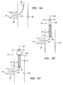
FIGS. 7 and 8 are cross-sectional side of a distal end of alternative embodiments of a balloon apparatus for delivering a stent into an ostium. - Turning to the drawings,
FIGS. 1 and 2 show an exemplary embodiment of aballoon apparatus 10 for delivering a stent orother prosthesis 40, e.g., into an ostium or other bifurcation between a main lumen and a branch lumen (not shown). Generally, theapparatus 10 includes a catheter or other elongatetubular member 12 having aproximal end 14, adistal end 16, and one or more lumens 18 extending between the proximal and distal ends 14, 16, thereby defining alongitudinal axis 20 between the proximal and distal ends 14, 16. Two balloons or other expandable members 22 are provided on thedistal end 16, e.g., a firstdistal balloon 22a and a secondproximal balloon 22b as shown. Optionally, one or more additional expandable members (not shown) may be provided on thedistal end 16 adjacent the first and/orsecond balloons - The
catheter 12 may be formed from one or more tubular bodies, e.g., having variable flexibility along its length. For example, thedistal end 16 may be substantially flexible to facilitate insertion through tortuous anatomy, e.g., terminating in a rounded or other substantiallyatraumatic tip 17. Thedistal end 16 may be sized and/or shaped for introduction into a body lumen, e.g., having a diameter between about one and seven millimeters (1-7 mm), or less than 1.5 mm. Theproximal end 14 may be substantially flexible or semi-rigid, e.g., having sufficient column strength to facilitate advancing thedistal end 16 through a patient's vasculature by pushing on theproximal end 14. Thecatheter 12 may be formed from plastic, metal, or composite materials, e.g., a plastic material having a wire, braid, or coil core, which may preventing kinking or buckling of thecatheter 12 during advancement. - As shown in
FIG. 1 , thecatheter 12 may include ahandle 30 on theproximal end 14, e.g., to facilitate manipulating theapparatus 10. Thehandle 30 may include one or more side ports 32 communicating with respective lumens 18 within thecatheter 12. Thehandle 30 may be molded, machined, or otherwise formed from plastic, metal, or composite material, e.g., providing an outer casing, which may be contoured or otherwise shaped to ease manipulation. Theproximal end 14 of thecatheter 12 may be attached to thehandle 30, e.g., by bonding, cooperating connectors, interference fit, and the like. Optionally, if the apparatus includes any actuatable components (not shown, see, e.g.,FIGS. 6A-6C ) on thedistal end 16, thehandle 30 may include one or more actuators (not shown), such as one or more slides, dials, buttons, and the like, for actuating or otherwise manipulating the components on thedistal end 16 from theproximal end 14, as explained further below. - As best seen in
FIG. 2 , thecatheter 12 includes at least three lumens 18 extending between the proximal ends 14, 16. For example, thecatheter 12 may include aninstrument lumen 18a that extends from aport 32a in thehandle 30 to anopening 34 in thedistal tip 17. Theinstrument lumen 18a may have sufficient size to allow a guidewire or other rail or instrument (not shown) to be inserted therethrough, e.g., to facilitate advancing thecatheter 12 over the rail, as explained further below. Optionally, thehandle 30 may include one or more seals (not shown) adjacent theport 32a, e.g., e.g., a hemostatic seal that prevents fluid, e.g., blood, from flowing proximally out of theport 32a, yet allows one or more instruments to be inserted therethrough and into theinstrument lumen 18a. - In addition, the
catheter 12 may includeinflation lumens respective side ports handle 30 through thecatheter 12 toopenings distal end 16. Eachopening respective balloon side ports handle 30 may include connectors, e.g., a luer lock connector (not shown), one or more seals (also not shown), and the like. A source of inflation media and/or vacuum, e.g., a syringe filled with saline (not shown), may be connected to theside ports FIG. 2 , the lumens 18 are disposed adjacent one another. Alternatively, the lumens 18 may be disposed in concentric or other arrangements within the body of thecatheter 12. In addition, if theapparatus 10 includes additional balloons (not shown) on thedistal end 16, thecatheter 12 may include one or more additional inflation lumens (also not shown), and thehandle 30 may include one or more additional ports (also not shown), similar to those shown and described with reference toFIG. 2 . - Alternatively, other configurations of lumens may be provided for delivering fluid to and/or aspirating fluid from one or both balloons 22. For example, a single lumen may be provided (not shown) that communicates with the interiors 23 of both balloons 22. This embodiment may allow the balloons 22 to be expanded and/or collapsed substantially simultaneously using a single syringe or other source of fluid/vacuum. In another alternative, the
catheter 12 may includeseparate inflation lumens handle 30 may include a single side port (not shown) to which a syringe or other source of fluid/vacuum may be connected. In this alternative, thehandle 30 may include a switch, stopcock, valve, or other device for selectively connecting one or bothinflation lumens inflation lumens individual balloon lumens stent 40 before removing theapparatus 10. In addition, the configuration may facilitate expanding theentire stent 40, e.g., after expanding and anchoring thefirst portion 42 and/or after flaring thesecond portion 44. - Turning to
FIG. 3 , in an alternative embodiment the apparatus 10' may include a catheter 12' including a plurality of tubular members disposed adjacent one another. The tubular members of the catheter 12' may be individual tubular bodies bonded or otherwise attached to one another along their lengths, a single body extruded or otherwise molded to include the tubular members as an integral unit, and the like. Otherwise, the materials and methods of the catheter 12' may be similar to the other embodiments described herein. Each tubular member may include a single or multiple lumens 18' therein. Optionally, different sections of the catheter 12' between the proximal end 14' and the distal end 16' may have different cross-sections. For example, the different sections along the length of the catheter 12' may be formed separately and attached to one another, e.g., by bonding, interference fit, melting or otherwise fusing the sections together, using an internal or external collar or sleeve (not shown), and the like. For example, as shown inFIG. 3 , the distal end 14' includes three lumens 18,' while the proximal end 16' may include only twolumens 18b'-18c.' - As shown in
FIG. 3 , the catheter 12' may include aninstrument lumen 18a' that extends along the distal end 16' of the catheter 12' between aproximal opening 32a' and adistal opening 34a' indistal tip 17.' Theproximal opening 32a' may be located a predetermined distance from thedistal tip 17,' e.g., between about eighty to three hundred millimeters (80-300 mm), to provide a "rapid-exchange" apparatus that may facilitate quickly exchanging guidewires within theinstrument lumen 18a.' Optionally, theproximal opening 32a' may include a ramped or tapered surface, e.g., to facilitate inserting and/or removing guidewires and the like into and out of theinstrument lumen 18a.' - Returning to
FIGS. 1 and 2 (although the materials and methods may be applicable to other embodiments described herein), the balloons 22 may be bonded or otherwise secured to thedistal end 16 of thecatheter 12. For example, ends 24, 26 of the balloons 22 may be attached to thedistal end 16 by bonding with an adhesive, by sonic welding, using an annular collar or sleeve, and the like. Thedistal balloon 22a includes a proximal end 24a attached to thedistal end 16 of thecatheter 12 proximal toopening 34c and adistal end 26a attached adjacent thedistal tip 17. Thedistal balloon 22a is expandable from a contracted condition (not shown), which may facilitate advancement within a patient's vasculature, to an enlarged condition, as shown inFIGS. 1 and 2 . - In the enlarged condition, the
distal balloon 22a includes anintermediate portion 28a having a substantially uniform cross-section, as best seen inFIG. 2 . Theintermediate portion 28a may have a length sufficient to receive at least a portion of astent 40 thereon (as shown inFIG. 1 ), e.g., between about seven and thirty millimeters (7-30 mm). Thedistal balloon 22a is be tapered, blunt, or otherwise transition from theintermediate portion 28a to the proximal anddistal ends 24a, 26a. - The
proximal balloon 22b includes aproximal end 24b attached to thedistal end 16 of thecatheter 12 proximal toopening 34b and adistal end 26b attached to thedistal balloon 22a, e.g., on or adjacent theintermediate portion 28a. Thedistal end 26b may be bonded with an adhesive, sonic welded, or otherwise attached to thedistal balloon 22a to provide a substantially fluid-tight seam or bond. Thus, the balloons 22 may be expandable independent of one another, yet be inseparable from one another, e.g., to prevent any gaps or spaces from developing between the balloons 22. In one embodiment, theproximal balloon 22b may have a length that is substantially shorter than thedistal balloon 22a, e.g., between about five to fifty millimeters (5-15 mm). In addition or alternatively, at least a transversedistal surface 28b of theproximal balloon 22b may have a length that is less than the length of theintermediate portion 28a of thedistal balloon 22a. - As shown in
FIG. 3 , theproximal balloon 22b' extends at least partially over thedistal balloon 22a.' Thedistal end 26b' of theproximal balloon 22b' extends over theintermediate portion 28a' of thedistal balloon 22a' and is attached over or adjacent to thedistal end 26a' of thedistal balloon 22a,' e.g., by bonding, sonic welding, and the like, as described elsewhere herein. This alternative may provide a seam that is substantially smaller, less bulky, more reliable, and/or easier to manufacture than the seam shown inFIG. 2 . - Turning to
FIG. 7 , an apparatus not part of the present invention is shown, theapparatus 210 is shown having acatheter 212, including adistal end 216, and a pair ofballoons 222a, 222b carried on thedistal end 216, similar to the other embodiments described herein. Similar components have been identified with similar reference numbers (although increased by 100 or 200). Unlike previous embodiments, adistal end 226b of the proximal balloon 222b may be attached to thedistal end 216 of thecatheter 212 adjacent or directly to aproximal end 224a of thedistal balloon 222a. For example, as shown, thedistal end 226b of the proximal balloon 222b may be bonded or otherwise attached over theproximal end 224a of thedistal balloon 222a. The proximal anddistal ends 224a, 226a of thedistal balloon 222a and theproximal end 224b of the proximal balloon 222b may be attached directly to thedistal end 216 of thecatheter 212, similar to the previous embodiments. Alternatively, theproximal end 224a of thedistal balloon 222a may be attached over thedistal end 226b of the proximal balloon 222b, which may be attached to thedistal end 216 of the catheter 212 (not shown). This arrangement may introduce a small gap between theintermediate region 228a and thetransverse surface 228b of the balloons 222 when they are expanded, as shown inFIG. 7 . - Alternatively, as shown in
FIG. 8 , thedistal end 326b of the proximal balloon 322b may be everted partially into the interior 323b of the proximal balloon 322b, e.g., to minimize any gap between the balloons 322. For example, the proximal anddistal ends 324a, 326a of the distal balloon 322a may be attached to thedistal end 316 of the catheter. Thedistal end 326b of the proximal balloon 322b may be attached to the proximal end 324a of the distal balloon 322a such that thetransverse surface 328b of the proximal balloon 322b is disposed immediately adjacent the intermediate region 328a of the distal balloon 322a. - Returning to
FIG. 2 , theproximal balloon 22b is expandable from a contracted condition (not shown), which may facilitate advancement through a patient's vasculature to an enlarged condition. As shown, theproximal balloon 22b is expandable independent of thedistal balloon 22a. In the enlarged condition, theproximal balloon 22b may include a transversedistal surface 28b that extends transversely relative to the longitudinal axis 18 and/orintermediate portion 28a when theproximal balloon 22b is expanded. As shown inFIG. 2 , thetransverse surface 28b may defme a substantially obtuse angle with theintermediate portion 28a of thedistal balloon 22a, e.g., between about ninety and one hundred fifty degrees (90-150°). - Alternatively, as shown in
FIGS. 4B and 4C , thetransverse surface 28b" may define a substantially acute angle with theintermediate portion 28a," e.g., between about sixty and ninety degrees (60-90°). In this alternative, thetransverse surface 28b" may define a concave shape or space into which thedistal balloon 22a" may at least partially nest as it expands, i.e., such that thedistal balloon 22a" expands against thetransverse surface 28b," as shown inFIG. 4C . - Returning to
FIGS. 1 and 2 , the balloons 22 may be formed from substantially inelastic material, e.g., PET, nylon, or PEBAX, such that the balloons 22 expand to a predetermined size in their enlarged conditions once sufficient fluid is introduced into the interiors 23 of the balloons 22. For example, thedistal balloon 22a may be expandable to an enlarged condition in which theintermediate portion 28a has a diameter between about two to seven millimeters (2-7 mm), while theproximal balloon 22b may be expandable to a diameter between about four to twenty millimeters (4-20 mm). Thedistal balloon 22a may be expandable to an enlarged condition that is smaller than theproximal balloon 22b, e.g., such that thetransverse surface 28b of theproximal balloon 22b extends radially outwardly from theintermediate portion 28a of thedistal balloon 22a when both balloons 22 are expanded. - Alternatively, one or both of the balloons 22 may be formed from substantially elastic material, e.g., silicone, polyurethane, or polyethylene, such that the balloons 22 may be expanded to a variety of sizes depending upon the volume and/or pressure of fluid within the interiors 23. For example, in the embodiment shown in
FIGS. 4A-4C , thedistal balloon 22a" may be substantially elastic, while theproximal balloon 22b" is substantially inelastic. As shown, astent 40 may be disposed over the balloons 22," e.g., such that afirst portion 42 of thestent 40 overlies thedistal balloon 22a" and asecond portion 44 of thestent 40 overlies theproximal balloon 22b." - As shown, the
proximal balloon 22b" is expandable from a contracted condition (shown inFIG. 4A ) to a predetermined size and shape in an enlarged condition (shown inFIGS. 4B and 4C ). As theproximal balloon 22b" is expanded, thetransverse surface 28b" bears against thesecond portion 44 of thestent 40, causing thesecond portion 44 to flare outwardly , as shown inFIG. 4B . If theproximal balloon 22b" is substantially inelastic, the resulting flare of thesecond portion 44 may adopt a predetermined shape, e.g., a substantially straight or curved conical shape. The predetermined shape may be configured to correspond at least partially to a shape of an ostium within a patient's vasculature, as explained further below. Optionally, theproximal balloon 22b" may be at least somewhat compliant, e.g., such that, once fully inflated, theproximal balloon 22b" may be pressed against tissue surrounding the ostium with sufficient force to cause theproximal balloon 22b" to conform at least partially to the shape of the ostium. This action may cause thesecond portion 44 of thestent 40 to deform further, e.g., to conform to the shape of the ostium, which may enhance seating or securing thestent 40 at a target location, as explained further below. - Turning to
FIG. 4C , thedistal balloon 22a" may be substantially elastic or otherwise more compliant than theproximal balloon 22b." After expanding theproximal balloon 22b" to deform thesecond portion 44 of the stent 40 (as inFIG. 4B ), thedistal balloon 22a" may be expanded, e.g., to cause thefirst portion 42 of thestent 40 to expand radially outwardly. As the internal pressure within thedistal balloon 22a" is increased (i.e., as additional fluid is delivered into thedistal balloon 22a"), thedistal balloon 22a" may be expanded through a range of sizes, causing thefirst portion 42 of thestent 40 to expand radially outwardly. - Because of its greater compliance and/or elasticity, the
distal balloon 22a" may be expanded until a desired size is attained, e.g., sufficient to dilate a branch body lumen communicating with the ostium or other target location, as explained further below. Fluoroscopy or other external imaging may be used as thedistal balloon 22a" is expanded, e.g., to monitor expansion of thefirst portion 42 of thestent 40, which may indicate the degree of dilation occurring within the target location. In addition, thedistal balloon 22a" may conform at least partially to the surrounding anatomy, e.g., distributing pressure more evenly along theintermediate portion 28a" such that thefirst portion 42 of the stent conforms to the substantially uniform shape of theintermediate portion 28a" of thedistal balloon 22a." Alternatively, thedistal balloon 22a" may be expandable to a predetermined size. This alternative may involve selecting anapparatus 10" having adistal balloon 22a" with an expanded size corresponding to the desired dilated size of the target location. - With additional reference to
FIGS. 4A-4C , theapparatus 10" (or any of the other embodiments described herein) may carry astent 40, which may be formed from a variety of materials that may be plastically deformed to allow expansion of thestent 40. For example, thestent 40 may be formed from metal, such as stainless steel, tantalum, MP35N, Niobium, Nitinol, and L605, plastic, or composite materials. In particular, the materials of thestent 40 may be plastically deformed under the pressures experienced when the balloons 22" are expanded, e.g., such that the first and/orsecond portions stent 40 are deformed beyond their elastic limit. Thus, when the balloons 22" are subsequently collapsed, thestent 40 may maintain its expanded configuration (e.g., that shown inFIG. 4C ) with minimal recoil, e.g., thestent 40 material may resist collapsing back towards its reduced configuration (e.g., that shown inFIG. 4A ) if the tissue surrounding the body lumen attempts to constrict or otherwise return to its occluded shape. - Alternatively, at least a portion of the
stent 40 may be self-expanding. For example, one or both of the first andsecond portions stent 40 may be formed from Nitinol or other shape memory or superelastic materials. - Optionally, the resistance of the
stent 40 to expansion may be varied along its length. This performance of thestent 40 may be based upon mechanical properties of the material, e.g., which may involve heat treating one or more portions of thestent 40 differently than other portions. In addition or alternatively, the structure of thestent 40 may be varied, e.g., by providing struts, fibers, or other components in different portions having different widths, thicknesses, geometry, and the like. In one embodiment, the material of thefirst portion 42 may require greater force to expand than thesecond portion 44. Thus, thesecond portion 44 may be more easily plastically deformed, which may allow theproximal balloon 22b" to be expanded using lower pressure than thedistal balloon 22a." - The
stent 40 may be a generally tubular structure, e.g., including openings in a tubular wall that facilitate expansion of thestent 40 and/or allow tissue ingrowth. For example, the stent may be an elongate tube that has slots or other openings formed in the tube wall, e.g., by laser cutting, mechanical cutting, chemical etching, machining, and the like. Alternatively, thestent 40 may be a braided or other structure, e.g., formed from one or wires or other filaments braided or otherwise wound in a desired manner. Additional possible stent structures may include helical coil wires or sheets. If desired, one or more portions of thestent 40 may include a membrane, film, or coating (not shown), e.g., to create a nonporous, partially porous, or porous surface between cells of thestent 40. - For example, the
second portion 44 of thestent 40 may include a substantially elastic membrane, e.g., PTFE, ePTFE, silicone, polyurethane, or polyethylene, that may be embedded into, coated onto, sandwiched around, or otherwise carried by thestent 40. The membrane may be substantially elastic such that the membrane may expand when thesecond portion 44 is flared or otherwise expanded. Alternatively, the membrane may be folded or otherwise compressed such that the membrane may unfold or otherwise to accommodate expansion as thestent 40 is expanded. The membrane may be provided on an outer and/or inner surface of thesecond portion 44. A membrane on the inner surface may facilitate recrossing thestent 40 at a later time after implantation. For example, after thestent 40 is implanted within a patient, it may be desirable to advance a guidewire or other instrument through the ostium into the branch vessel, e.g., to perform another procedure. This may occur during the same surgical procedure, or some time after the patient has recovered, e.g., when the branch vessel, lesion, or main vessel need subsequent treatment. The membrane may prevent the tip of a guidewire or other instrument from catching or tangling in the struts, cells, wires, or other structures of thestent 40. Instead, the membrane may provide a substantially smooth, possibly lubricious surface that may guide a guidewire through thestent 40 into the branch vessel. - In addition or alternatively, a membrane on the
stent 40 may carry therapeutic or other compounds or materials. For example, a membrane on an outer surface of thestent 40 may be pressed into contact with the plaque, damaged tissue, or other material of the lesion, allowing the compound to act to enhance healing or otherwise treat the lesion. - Optionally, the
stent 40 may include one or more radiopaque or other markers (not shown), e.g., to facilitate monitoring thestent 40 during advancement, positioning, and/or expansion. For example, a band of radiopaque material, e.g., gold, platinum, iridium, tungsten, or their alloys, may be provided on each end of thestent 40 and/or adjacent the location where the first andsecond portions apparatus 10 may include one or more radiopaque markers (not shown), e.g., at one or more predetermined locations on thedistal end 16 of thecatheter 12 and/or on one or both balloons 22. For example, a band of radiopaque material (not shown) may be provided on or under the ends of theintermediate portion 28a of thedistal balloon 22a or thetransverse surface 28b of theproximal balloon 22b, e.g., to facilitate positioning theapparatus 10. - In addition or alternatively, the
stent 40 may carry one or more therapeutic or other compounds (not shown) that may enhance or otherwise facilitate treatment of a target location within a patient's body. For example, thestent 40 may carry compounds that prevent restenosis at the target location. - Turning to
FIGS. 5A-5F , an exemplary method is shown for delivering astent 40 into anostium 90, e.g., using anapparatus 10, which may be any of the embodiments described herein, and not necessarily limited to the embodiment shown and described with reference toFIGS. 1 and 2 . Theostium 90 may be an opening in a wall of a first ormain body lumen 92 that communicates with a second orbranch body lumen 94. Themain body lumen 92 may be the aortic root and thebranch body lumen 94 may be a coronary artery. It will be appreciated that the apparatus and methods described herein may be applicable to a variety of bifurcations or branch body lumens that extend transversely, e.g., laterally or substantially perpendicular, from a main body lumen, e.g., within a patient's vasculature or other systems. - An occlusion or
other lesion 96 may exist at and/or adjacent to theostium 90, e.g., extending at least partially into thebranch 94. Thelesion 96 may include atherosclerotic plaque or other material that partially or completely occludes blood or other fluid flow between themain body lumen 92 and thebranch 94. - Initially, as shown in
FIG. 5A , aguidewire 98 or other rail may be introduced from themain body lumen 92 through theostium 90 into thebranch 94. As shown, thelesion 96 at theostium 90 partially occludes theostium 90 and extends into thebranch 94. Theguidewire 98 may be placed using conventional methods. For example, a percutaneous puncture or cut-down may be created at a peripheral location (not shown), such as a femoral artery, carotid artery, or other entry site, and theguidewire 98 may be advanced through the patient's vasculature from the entry site, e.g., alone or with the aid of a guide catheter or sheath (not shown). If thelesion 96 completely occludes thebranch 94, theguidewire 98 may be directed through the occlusion or other devices (not shown) may be advanced over theguidewire 98 or otherwise in conjunction with theguidewire 98 to create a passage through thelesion 96 for theguidewire 98. - After the
guidewire 98 is directed into thebranch 94 beyond thelesion 96, it may be desirable to at least partially dilate thelesion 96. For example, a balloon catheter (not shown) may be advanced over theguidewire 98 into and through thelesion 96, whereupon a balloon or other element on the catheter may be expanded to at least partially dilate thelesion 96. If desired, other procedures may also be performed at thelesion 96, e.g., to soften, remove, or otherwise treat plaque or other material forming thelesion 96, before thestent 40 is implanted. After completing any such procedures, instruments advanced over theguidewire 98 may be removed. - Optionally, a guide catheter (not shown) may be advanced over the
guidewire 98 into themain body lumen 92, e.g., until a distal end of the guide catheter is disposed adjacent or proximal to theostium 90. The guide catheter may be used to advance one or more instruments (such as those just described) over theguidewire 98 and into themain body lumen 92 and/orbranch body lumen 94. In addition, the guide catheter may facilitate advancement of theapparatus 10 into themain body lumen 92 and/or into thebranch 94, in addition to or instead of theguidewire 98. - Turning to
FIG. 5B , adistal end 16 ofapparatus 10 may be advanced over the guidewire 98 (and/or through the guide catheter, not shown) from the entry site into themain body lumen 92 with the balloons 22 in their contracted conditions. When thedistal tip 17 is adjacent to theostium 90, as shown inFIG. 5C , theproximal balloon 22b may be expanded, e.g., by delivering saline, nitrogen, or other inflation media into the interior 23b (see, e.g.,FIG. 2 ) of theproximal balloon 22b from a syringe or other fluid source (not shown) coupled to the proximal end (also not shown) of theapparatus 10. As theproximal balloon 22b is expanded, asecond portion 44 of thestent 40 is expanded, e.g., into a flared configuration conforming to thetransverse surface 28b of theproximal balloon 22b. - Turning to
FIG. 5D , with thesecond portion 44 flared or otherwise expanded, theapparatus 10 may be advanced distally over theguidewire 98 into theostium 90, e.g., until thesecond portion 44 contacts the wall of themain body lumen 92 surrounding theostium 90. As theapparatus 10 is advanced, thedistal tip 17 of thecatheter 12 enters theostium 90 and passes through thelesion 96 into thebranch 94, e.g., until thefirst portion 42 of thestent 40 is disposed within thelesion 96, as shown. Optionally, if thestent 40 includes one or more radiopaque markers, fluoroscopy or other external imaging may be used to ensure that thestent 40 is positioned properly into theostium 90 andbranch 94. - Turning to
FIG. 5E , with thefirst portion 42 disposed within thelesion 96, thedistal balloon 22a may be expanded, thereby dilating or otherwise lining thebranch 94 within thelesion 96. For example, as thefirst portion 42 of thestent 40 is expanded, plaque and/or other material defining thelesion 96 may be directed radially outwardly to dilate thelesion 96 to a diameter comparable to thebranch 94 downstream of thelesion 96. Again, if thestent 40 and/orapparatus 10 include one or more radiopaque markers or if contrast is delivered into themain body lumen 92 and/or into thebranch 94, theostium 90 and/orlesion 96 may be imaged to confirm the position of thestent 40 and/or to monitor the extent of dilation of thelesion 96, e.g., until a desired diameter or other cross-section is attained. - Optionally, additional distal force may be applied to the
apparatus 10, e.g., to force thesecond portion 44 of thestent 40 against theostium 90. This pushing may cause thesecond portion 44 to plastically deform further, e.g., to at least partially conform to the shape and/or contour of theostium 90. This additional force may be applied before, during, or after inflation of thedistal balloon 22a. - In addition or alternatively, if the
proximal balloon 22b is elastically expandable, theproximal balloon 22b may be expanded initially (e.g., during the stage described with reference toFIGS.5C and5D ) to a first enlarged configuration to allow thesecond portion 44 of thestent 40 to contact and/or otherwise seat into theostium 90. Once thedistal balloon 22a is inflated to expand thefirst portion 42 of thestent 40 and dilate thelesion 96 to a desired extent (e.g., as described with reference toFIG. 5E ), theproximal balloon 22b may be inflated further, e.g., to further expand thesecond portion 44 of thestent 40 or cause thesecond portion 44 to conform further to the contour of theostium 40. This additional expansion may further seat and/or secure thestent 40, and/or to dilate theostium 90. Alternatively, thedistal balloon 22a may be at least partially expanded before expanding theproximal balloon 22b. - Turning to
FIG. 5F , once thestent 40 is expanded and/or positioned in a desired manner, the balloons 22 may be collapsed, e.g., by evacuating the inflation media using a syringe or other device (not shown) at the proximal end (also not shown) of thecatheter 12. The balloons 22 may be deflated simultaneously or sequentially, e.g., first deflating thedistal balloon 22a, and then deflating theproximal balloon 22b (e.g., after applying further distal force, if desired). With the balloons 22 collapsed, theapparatus 10 is withdrawn from themain body lumen 92 and out of the patient's body. If a guide catheter or other sheath (not shown) is used, the guide catheter or sheath may be advanced against or into theostium 90 before theapparatus 10 is removed, e.g., to facilitate withdrawing the balloons 22 without dislodging thestent 40. The guidewire 98 (and/or the guide catheter or sheath, if used) may be removed before, after, or simultaneously with theapparatus 10. Thus, thestent 40 remains in place to dilate thelesion 96. - Although the methods described include advancing the
apparatus 10 into thebranch 94 from themain body lumen 92, it will be appreciated that, in some procedures, theapparatus 10 may be advanced from thebranch 94 into themain body lumen 92. In such procedures, the configuration of the balloons 22 may be reversed, i.e., the location of the proximal anddistal balloons apparatus 10 may include more than two balloons (not shown), which may be expanded independently of one another, e.g., to dilate, flare, or otherwise shape a stent during deployment in a desired manner. For example, a proximal balloon may be expanded first, and then individual balloons may be expanded sequentially, e.g., further distally along the distal end of the catheter, to expand the stent into a desired configuration within the ostium and/or branch. - The apparatus and method described herein may allow a lesion to be dilated even if the plaque or other material extends from the branch at least partially into the ostium and/or into the main body lumen. For example, the flared shape of the
second portion 44 of thestent 40 shown inFIG. 5F may substantially reduce the risk of plaque extending inwardly around thestent 40 even after deployment. In contrast, a straight or unflared stent (not shown) may be deployed too far into the ostium, e.g., such that plaque within the lesion may remain exposed between the end of the stent and the main body lumen, which may at least partially occlude the ostium. Alternatively, a straight or unflared stent may be deployed such that it extends partially from the ostium into the main body lumen. This configuration may reduce the risk of at least partially occluding the ostium, but may make subsequently accessing the branch more difficult, e.g., if additional treatment is required at a later time. - Turning to
FIGS. 6A-6C , another example of anapparatus 110 is shown that includes acatheter 112 including aproximal end 114, adistal end 116, and a plurality of lumens (not shown for clarity) extending therebetween, thereby defining alongitudinal axis 120. A pair of balloons 122 may be provided on thedistal end 116, e.g., adistal balloon 122a and aproximal balloon 122b overlapping or otherwise adjacent thedistal balloon 122a, similar to the other embodiments described herein. Thecatheter 112 may include one or more lumens (not shown), e.g., an instrument lumen and an inflation lumen for each balloon 122. Astent 40 or other prosthesis may be carried on thedistal end 116, e.g., surrounding or otherwise over the balloons 122, also similar to the embodiments described herein. - Unlike the previous embodiments, the
apparatus 110 includessheath 150 that at least partially covers thestent 40. For example, with the balloons 122 collapsed and thestent 40 in a contracted configuration, thesheath 150 may cover both a first ordistal portion 42 and a second orproximal portion 44 of thestent 40, as shown inFIG. 6A . Thesheath 150 may protect thestent 40 and/or balloons 122 during advancement of theapparatus 110, and/or may provide a rounded or otherwise substantially atraumatic tip for theapparatus 110, which may facilitate advancing thedistal end 116 through a patient's vasculature. - As shown, the
sheath 150 includes aproximal end 152 that covers thestent 40 and adistal end 154 that is disposed distal to thestent 40. Thedistal end 154 may have a tapered, rounded, or other shape, e.g., to provide a substantially atraumatic tip for theapparatus 110. A wire, cable, orother actuating element 160 may be coupled to the distal 154 and may extend proximally through or along thecatheter 112 to theproximal end 114. For example, thecatheter 112 may include an additional lumen and/or a groove or track (not shown) that accommodates theactuating element 160. Thecatheter 112 may include ahandle 130 on theproximal end 114 including a slider or other control oractuator 162 coupled to theactuating element 160. As theactuator 162 is directed distally, theactuating element 160 may push thesheath 150 distally, e.g., to expose all or a portion of thestent 40. - In an exemplary example, the
actuator 162 may be directed from a proximal position (shown inFIG. 6A ) to a first distal position, as shown inFIG. 6B , in which thefirst portion 42 of thestent 40 remains covered while thesecond portion 44 of thestent 40 is exposed. In this position, theproximal balloon 122b may be inflated, as shown, to flare or otherwise direct thesecond portion 42 of thestent 40 radially outwardly. Alternatively, if thesecond portion 44 of thestent 40 is self-expanding, thesecond portion 44 may automatically flare outwardly when thesheath 150 is directed to the first distal position. In this alternative, theproximal balloon 122b may be inflated to further flare or expand thesecond portion 44. - As shown in
FIG. 6C , theactuator 162 may also be directed to a second distal position in which thefirst portion 42 of thestent 40 is exposed from thesheath 150. Once exposed, thedistal balloon 122a may be inflated to expand thefirst portion 42 of thestent 40. Alternatively, thefirst portion 42 of thestent 40 may also be self-expanding such that thefirst portion 42 at least partially expands when thesheath 150 is directed to the second distal position. Thereafter, thedistal balloon 122a may be inflated to further expand and/or shape thefirst portion 42 of thestent 40. - Alternatively, the
sheath 150 may only cover thefirst portion 42 of the stent 40 (not shown). Optionally, an additional sheath, catheter, or other tubular member (not shown) may be provided that extends over thecatheter 112 from theproximal end 114 to thedistal end 116 and over at least thesecond portion 44 of thestent 40. If desired, this tubular member may mate with theproximal end 152 of thesheath 150 to provide a smooth or other desired transition. In yet another alternative, one or more other constraints may be provided over thestent 40, e.g., one or more filaments or other bindings (not shown) that may be wrapped around at least a portion of thestent 40. Such constraint(s) may be removed from thehandle 130, e.g., by directing an actuator proximally to pull the bindings apart or otherwise from around thestent 40. - Returning to
FIG. 6A , during use, theapparatus 110 may be provided initially with the balloons 122 collapsed and thestent 40 disposed over the balloons 122 in a contracted configuration. Thesheath 150 may extend over thefirst portion 42 and, optionally, over thesecond portion 44 of thestent 40, as shown inFIG. 6A . In this configuration, theapparatus 110 may be introduced into a patient's body and advanced into amain body lumen 92, similar toFIG. 5B . If thesheath 150 initially covers thesecond portion 42 of thestent 40, thesheath 150 may be directed distally to expose thesecond portion 42, as shown inFIG. 6B . Alternatively, if a separate tubular member covers thesecond portion 44, the tubular member may be retracted proximally to uncover thesecond portion 44. - Once exposed, the
proximal balloon 122b may be inflated to flare or otherwise expand thesecond portion 42 of thestent 40, as shown inFIG. 6B , and similar to the procedure shown and described with reference toFIG. 5C . Similar toFIG. 5D , theapparatus 110 may be advanced to direct thesheath 150, andfirst portion 42 of thestent 40 covered thereby, into theostium 90 and through alesion 96 at least partially into thebranch 94. Turning toFIG. 6C , thesheath 150 may then be directed distally to uncover thefirst portion 42 of thestent 40, whereupon thedistal balloon 122a may be expanded, e.g., to dilate thelesion 96, similar toFIG. 5E . Additional inflation and/or manipulation of the balloons 122 and/orapparatus 110 may be completed, similar to the previous embodiments, e.g., to enhance seating thestent 40 and/or conforming thesecond portion 44 to the contour of theostium 90. Once the stent is properly deployed, the balloons 122 may be collapsed, and theapparatus 110 may be removed, leaving thestent 40 to dilate thelesion 96. - Although balloons are described for expanding a stent, it will be appreciated that other expandable members may be provided on the apparatus described herein, . For example, a pair mechanically expandable members may be provided on the distal end of a catheter that may be actuated from the proximal end of the catheter. A skin or other material may be provided that covers an expandable frame to cause the expandable members to expand to desired configurations, e.g., similar to the proximal and distal balloons described herein.
Claims (16)
- An apparatus (10, 10') for delivering a prosthesis (40) into an ostium of a body lumen, comprising:an elongate member (12, 12') comprising a proximal end (14, 14'), a distal end (16, 16') sized for introduction into a body lumen, and a longitudinal axis (20) extending therebetween;a first expandable member (22a, 22a') comprising proximal (24a) and distal ends (26a, 26a') attached on the distal end (16, 16') of the elongate member (12, 12'), the first expandable member (22a, 22a') being expandable from the proximal end (14, 14') of the elongate member (12, 12'), the first expandable member (22a, 22a') comprising an intermediate portion (28a, 28a') having a length for receiving a first portion (42) of a tubular prosthesis (40) thereon, a substantially uniform cross-section, and a tapered distal portion; anda second expandable member (22b, 22b') on the distal end (16, 16') of the elongate member (12, 12') adjacent the first expandable member (22a, 22a'), the second expandable member (22b, 22b') comprising a proximal end (24b) attached on the elongate member distal end (16, 16') proximal to the first expandable member proximal end (24a), characterised by a portion of the second expandable member (22b, 22b') extending over the intermediate (28a, 28a') portion of the first expandable member (22a, 22a') and being attached to the first expandable member (22a, 22a') such that a distal end (26b') of the second expandable member (22b, 22b') is adjacent the first expandable member distal end (26a, 26a'), the second expandable member (22b, 22b') being expandable from a proximal end (14, 14') of the elongate member (12, 12') independently of the first expandable member (22a, 22a') for expanding a second portion (44) of a tubular prosthesis to an enlarged condition while said first portion (42) remains in a contracted condition, the second expandable member (22b, 22b') formed from material that expands the second expandable member (22b, 22b') to a predetermined shape such that, in an enlarged condition, the second expandable member (22b, 22b') defines a distal surface (28b, 28b') adjacent the intermediate portion (28a, 28a') of the first expandable member (22a, 22a') that extends transversely outwardly and proximally from the intermediate portion (28a, 28a') when the second expandable member (22b, 22b') is expanded for expanding the second portion (44) of the prosthesis (40) to a flared condition to facilitate placement of the prosthesis (40) within an ostium.
- The apparatus of claim 1, further comprising a prosthesis comprising a first portion surrounding the intermediate portion of the first expandable member and a second portion surrounding the distal surface of the second expandable member such that the second portion defines a flared shape that tapers outwardly from the first portion.
- The apparatus of any preceding claim, wherein the portion of the second expandable member extending over the intermediate portion of the first expandable member is attached to the intermediate portion of the first expandable member.
- The apparatus of any preceding claim, further comprising a source of fluid connected to the proximal end of the elongate member such that the source of fluid communicates with the interiors of the first and second expandable members via first and second lumens within the elongate member, the source of fluid configured for:expanding the second expandable member to cause the second portion of the prosthesis to flare radially outwardly from the first portion while the first portion of the prosthesis remains in the contracted condition after directing the distal end of the elongate member into a main lumen adjacent an ostium of a branch lumen; andexpanding the first expandable member after directing the distal end into the ostium to cause the expanded second portion to engage a wall of the main lumen surrounding the ostium, the first expandable member expanding the first portion of the prosthesis to contact a wall of the branch lumen.
- The apparatus of claim 4, wherein the source of fluid is further configured for expanding the second expandable member after expanding the first expandable member to expand the second portion of the prosthesis further.
- The apparatus of claim 4 or 5, wherein the second expandable member comprises compliant or semi-compliant material such that, after expanding the second expandable member, the distal end of the elongate member may be directed into the ostium with sufficient force to cause the expanded second portion to conform at least partially to the shape of the ostium.
- The apparatus of any preceding claim, wherein an internal pressure necessary to expand the second expandable member is less than an internal pressure necessary to expand the first expandable member.
- The apparatus of any preceding claim, wherein the second portion is more easily plastically deformed than the second portion, which allows the second expandable member to be expanded using lower pressure than the first expandable member.
- The apparatus of claim 1, further characterized by the elongate member (12, 12') comprising first (18c, 18c') and second lumens (18b, 18b') extending between the proximal (14, 14') and distal ends (16, 16');
the first expandable member (22a, 22a') comprising an interior (23a, 23a') communicating with the first lumen (18c, 18c');
the second expandable member (22b, 22b') comprising an interior (23b, 23b') communicating with the second lumen (18b, 18b'). - The apparatus of claim 1 or 9, further comprising:a prosthesis (40) comprising a first portion (42) surrounding the intermediate portion (28a, 28a') of the first expandable member (22a, 22a'), and a second portion (44) surrounding a distal surface (28b, 28b') of the second expandable member (22b, 22b') extending proximally from the intermediate portion (28a, 28a'), the first portion (42) having a first length and the second portion (44) having a second length, the second length shorter than the first length, the first portion (42) comprising material that requires greater force to expand than the second portion (44);the second expandable member (22b, 22b') being expandable independently of the first expandable member (22a, 22a') for expanding the second portion (44) to an enlarged condition while the first portion (42) remains in a contracted condition, the second expandable member (22b, 22b') formed from material that expands the second expandable member (22b, 22b') to a predetermined shape such that the distal surface (28b, 28b') of the second expandable member (22b, 22b') extends transversely outwardly and proximally from the intermediate portion (28a, 28a'), the prosthesis (40) overlying the distal surface (28b, 28b') of the second expandable member (22b, 22b') such that the second portion (44) flares radially outwardly and proximally away from the first portion (42), the first expandable member (22a, 22a') being expandable for expanding the first portion (42) to an enlarged condition that is smaller than the second portion (44) in its enlarged condition.
- The apparatus of claim 10, further comprising a constraint for maintaining the first portion in the contracted condition while the second expandable member is expanded.
- The apparatus of claim 11, wherein the constraint comprises a tubular member overlying the first portion, the tubular member being movable between a first position covering the first portion and a second position uncovering the first portion.
- The apparatus of claim 12, wherein the tubular member is movable between a third position covering the second portion and the first position.
- The apparatus of claim 10, wherein the intermediate portion of the first expandable member has a length at least as long as the first length.
- The apparatus of claim 4 or 9, wherein the elongate member comprises a port on the proximal end and a valve for selectively connecting at least one of the first and second lumens to the port.
- The apparatus of claim 15, wherein the valve is movable to a position wherein both of the first and second lumens are connected to the port such that the first and second expandable members may be expanded or collapsed substantially simultaneously.
Applications Claiming Priority (2)
| Application Number | Priority Date | Filing Date | Title |
|---|---|---|---|
| US11/136,266 US7862601B2 (en) | 2005-05-23 | 2005-05-23 | Apparatus and methods for delivering a stent into an ostium |
| PCT/US2006/020105 WO2006127824A1 (en) | 2005-05-23 | 2006-05-23 | Apparatus and methods for delivering a stent into an ostium |
Publications (3)
| Publication Number | Publication Date |
|---|---|
| EP1901797A1 EP1901797A1 (en) | 2008-03-26 |
| EP1901797B1 true EP1901797B1 (en) | 2013-07-03 |
| EP1901797B8 EP1901797B8 (en) | 2013-08-21 |
Family
ID=36792800
Family Applications (1)
| Application Number | Title | Priority Date | Filing Date |
|---|---|---|---|
| EP06771081.4A Active EP1901797B8 (en) | 2005-05-23 | 2006-05-23 | Apparatus for delivering a stent into an ostium |
Country Status (5)
| Country | Link |
|---|---|
| US (2) | US7862601B2 (en) |
| EP (1) | EP1901797B8 (en) |
| JP (1) | JP5227170B2 (en) |
| CA (1) | CA2609176A1 (en) |
| WO (1) | WO2006127824A1 (en) |
Families Citing this family (41)
| Publication number | Priority date | Publication date | Assignee | Title |
|---|---|---|---|---|
| US9034025B2 (en) | 2005-05-23 | 2015-05-19 | Ostial Corporation | Balloon catheters and methods for use |
| US10092429B2 (en) * | 2005-08-22 | 2018-10-09 | Incept, Llc | Flared stents and apparatus and methods for delivering them |
| WO2006127825A1 (en) * | 2005-05-23 | 2006-11-30 | Incept Llc | Apparatus and methods for locating an ostium of a vessel |
| US7766893B2 (en) * | 2005-12-07 | 2010-08-03 | Boston Scientific Scimed, Inc. | Tapered multi-chamber balloon |
| US8518100B2 (en) * | 2005-12-19 | 2013-08-27 | Advanced Cardiovascular Systems, Inc. | Drug eluting stent for the treatment of dialysis graft stenoses |
| US8398695B2 (en) * | 2006-11-03 | 2013-03-19 | Boston Scientific Scimed, Inc. | Side branch stenting system using a main vessel constraining side branch access balloon and side branching stent |
| US8414611B2 (en) * | 2006-11-03 | 2013-04-09 | Boston Scientific Scimed, Inc. | Main vessel constraining side-branch access balloon |
| US20080132988A1 (en) * | 2006-12-01 | 2008-06-05 | Scimed Life Systems, Inc. | Balloon geometry for delivery and deployment of shape memory polymer stent with flares |
| ITMI20062333A1 (en) | 2006-12-05 | 2008-06-06 | Mario Salerno | DEVICE TO ASSIST THE SCLORESANT TREATMENT OF VARICOSE VEINS |
| US9486345B2 (en) * | 2008-01-03 | 2016-11-08 | Covidien Lp | Methods and systems for placement of a stent adjacent an ostium |
| US8353927B2 (en) * | 2009-05-04 | 2013-01-15 | Merit Medical Systems, Inc. | Radial artery compression device |
| AU2009244447B2 (en) * | 2008-05-06 | 2013-09-19 | The Cleveland Clinic Foundation | Balloon for a body lumen and method of use |
| EP2344230B1 (en) * | 2008-11-03 | 2016-04-27 | Advanced Catheter Therapies, Inc. | Occlusion perfusion catheter |
| US8758423B2 (en) * | 2009-06-18 | 2014-06-24 | Graftcraft I Goteborg Ab | Device and method for treating ruptured aneurysms |
| US9468548B2 (en) * | 2010-04-02 | 2016-10-18 | Cappella, Inc. | Systems and methods for delivering a stent to a body lumen |
| WO2012054762A2 (en) * | 2010-10-20 | 2012-04-26 | Medtronic Ardian Luxembourg S.A.R.L. | Catheter apparatuses having expandable mesh structures for renal neuromodulation and associated systems and methods |
| US9108024B2 (en) * | 2012-09-28 | 2015-08-18 | Avent, Inc. | Retention component for placement of enteral feeding tubes |
| US9839543B2 (en) | 2013-03-14 | 2017-12-12 | Cook Medical Technologies Llc | Multi-stage balloon catheter |
| US10842969B2 (en) | 2013-10-25 | 2020-11-24 | Mercator Medsystems, Inc. | Systems and methods of treating malacia by local delivery of hydrogel to augment tissue |
| US9861726B2 (en) * | 2014-09-15 | 2018-01-09 | Covidien Lp | Coupling a body conduit to tissue |
| CN104398329A (en) * | 2014-09-30 | 2015-03-11 | 浦易(上海)生物技术有限公司 | Completely-degradable net-shaped nasolacrimal stent and implantation system thereof |
| US9980840B2 (en) | 2014-12-08 | 2018-05-29 | Cook Medical Technologies Llc | Delivery device with an expandable positioner for positioning a prosthesis |
| US11160956B1 (en) * | 2015-02-06 | 2021-11-02 | David M. Hoganson | Balloon dilator |
| DE102015107038A1 (en) * | 2015-05-06 | 2016-11-10 | Bentley Innomed Gmbh | double balloon |
| EP3291726A4 (en) * | 2015-05-07 | 2019-01-02 | Corfigo, Inc. | Non-occlusive circumferential vascular ablation device |
| US10603195B1 (en) * | 2015-05-20 | 2020-03-31 | Paul Sherburne | Radial expansion and contraction features of medical devices |
| DE102015112390A1 (en) * | 2015-07-29 | 2017-02-02 | Bentley Innomed Gmbh | balloon catheter |
| EP3377165B1 (en) * | 2015-11-20 | 2022-12-28 | Boston Scientific Scimed, Inc. | Balloon catheter |
| US10470905B2 (en) | 2016-03-25 | 2019-11-12 | Ostial Corporation | Balloon catheters and methods for use |
| US11207505B2 (en) * | 2017-01-06 | 2021-12-28 | Cardiofocus, Inc. | Balloon catheter and fluid management system thereof |
| IT201700055981A1 (en) * | 2017-05-23 | 2018-11-23 | Lorenzo Nicola Di | Device for the treatment of cardiovascular diseases |
| US10321914B2 (en) * | 2017-06-14 | 2019-06-18 | William Joseph Drasler | Positionable perivalvular occlusion device |
| US10350395B2 (en) | 2017-06-23 | 2019-07-16 | Cook Medical Technologies Llc | Introducer for lumen support or dilation |
| US20180369548A1 (en) * | 2017-06-23 | 2018-12-27 | Cook Medical Technologies Llc | Dual balloon for lumen support or dilation |
| US11850386B2 (en) | 2018-10-03 | 2023-12-26 | Ostial Corporation | Inflation devices and systems for balloon catheters and methods for use |
| EP3877033A4 (en) * | 2018-11-08 | 2022-06-22 | Ostial Corporation | Dual balloon catheters and methods for use |
| CA3185009A1 (en) * | 2020-06-11 | 2021-12-16 | Edwards Lifesciences Corporation | Inflatable bodies, systems, and methods for expanding implants |
| US11672683B2 (en) * | 2020-10-05 | 2023-06-13 | National Guard Health Affairs | Bifunctional balloon-expandable and self-expandable stent |
| WO2023014792A1 (en) * | 2021-08-04 | 2023-02-09 | Boston Scientific Scimed, Inc. | Ostial stent delivery device, system, and method |
| CN114099100B (en) * | 2022-01-26 | 2022-06-03 | 上海微创心脉医疗科技(集团)股份有限公司 | Branch sheath and blood vessel support conveyer |
| CN114984420A (en) * | 2022-06-20 | 2022-09-02 | 柏为(武汉)医疗科技股份有限公司 | Sinus ostial stent expansion device and sinus ostial stent |
Family Cites Families (88)
| Publication number | Priority date | Publication date | Assignee | Title |
|---|---|---|---|---|
| JPS5431825Y2 (en) * | 1975-06-30 | 1979-10-04 | ||
| US4327736A (en) * | 1979-11-20 | 1982-05-04 | Kanji Inoue | Balloon catheter |
| US4921483A (en) | 1985-12-19 | 1990-05-01 | Leocor, Inc. | Angioplasty catheter |
| US4744366A (en) * | 1986-09-10 | 1988-05-17 | Jang G David | Concentric independently inflatable/deflatable multiple diameter balloon angioplasty catheter systems and method of use |
| US4763654A (en) * | 1986-09-10 | 1988-08-16 | Jang G David | Tandem independently inflatable/deflatable multiple diameter balloon angioplasty catheter systems and method of use |
| US4950227A (en) | 1988-11-07 | 1990-08-21 | Boston Scientific Corporation | Stent delivery system |
| US5295958A (en) * | 1991-04-04 | 1994-03-22 | Shturman Cardiology Systems, Inc. | Method and apparatus for in vivo heart valve decalcification |
| FR2688401B1 (en) | 1992-03-12 | 1998-02-27 | Thierry Richard | EXPANDABLE STENT FOR HUMAN OR ANIMAL TUBULAR MEMBER, AND IMPLEMENTATION TOOL. |
| US5540712A (en) | 1992-05-01 | 1996-07-30 | Nitinol Medical Technologies, Inc. | Stent and method and apparatus for forming and delivering the same |
| US5415635A (en) * | 1992-07-21 | 1995-05-16 | Advanced Cardiovascular Systems, Inc. | Balloon assembly with separately inflatable sections |
| JP3141601B2 (en) * | 1993-01-22 | 2001-03-05 | 株式会社ニッショー | CATHETER FOR TREATMENT OF LOCAL ANEMIA AND TREATMENT DEVICE USING THE SAME |
| SE505436C2 (en) | 1993-04-27 | 1997-08-25 | Ams Medinvent Sa | prostatic stent |
| US5409495A (en) * | 1993-08-24 | 1995-04-25 | Advanced Cardiovascular Systems, Inc. | Apparatus for uniformly implanting a stent |
| US5545209A (en) * | 1993-09-30 | 1996-08-13 | Texas Petrodet, Inc. | Controlled deployment of a medical device |
| US5607444A (en) * | 1993-12-02 | 1997-03-04 | Advanced Cardiovascular Systems, Inc. | Ostial stent for bifurcations |
| DE4418336A1 (en) | 1994-05-26 | 1995-11-30 | Angiomed Ag | Stent for widening and holding open receptacles |
| US5609605A (en) | 1994-08-25 | 1997-03-11 | Ethicon, Inc. | Combination arterial stent |
| US5549551A (en) * | 1994-12-22 | 1996-08-27 | Advanced Cardiovascular Systems, Inc. | Adjustable length balloon catheter |
| US5749851A (en) * | 1995-03-02 | 1998-05-12 | Scimed Life Systems, Inc. | Stent installation method using balloon catheter having stepped compliance curve |
| BE1009278A3 (en) | 1995-04-12 | 1997-01-07 | Corvita Europ | Guardian self-expandable medical device introduced in cavite body, and medical device with a stake as. |
| DE19526784A1 (en) | 1995-07-21 | 1997-01-23 | Bavaria Med Tech | Double balloon catheter |
| US5868704A (en) * | 1995-09-18 | 1999-02-09 | W. L. Gore & Associates, Inc. | Balloon catheter device |
| US5632762A (en) * | 1995-11-09 | 1997-05-27 | Hemodynamics, Inc. | Ostial stent balloon |
| US8728143B2 (en) * | 1996-06-06 | 2014-05-20 | Biosensors International Group, Ltd. | Endoprosthesis deployment system for treating vascular bifurcations |
| US5725535A (en) * | 1996-09-20 | 1998-03-10 | Hegde; Anant V. | Multiple balloon stent delivery catheter and method |
| EP0835673A3 (en) * | 1996-10-10 | 1998-09-23 | Schneider (Usa) Inc. | Catheter for tissue dilatation and drug delivery |
| US6325826B1 (en) * | 1998-01-14 | 2001-12-04 | Advanced Stent Technologies, Inc. | Extendible stent apparatus |
| ATE539702T1 (en) * | 1996-11-04 | 2012-01-15 | Advanced Stent Tech Inc | DEVICE FOR EXPANDING A STENT AND METHOD FOR DEPLOYING IT |
| US5749890A (en) * | 1996-12-03 | 1998-05-12 | Shaknovich; Alexander | Method and system for stent placement in ostial lesions |
| US6096071A (en) * | 1998-03-26 | 2000-08-01 | Yadav; Jay S. | Ostial stent |
| DE69835634T3 (en) | 1997-05-07 | 2010-09-23 | Cordis Corp. | Intravascular stent and insertion system (obstruction of the ostium of a vessel) |
| US6409755B1 (en) | 1997-05-29 | 2002-06-25 | Scimed Life Systems, Inc. | Balloon expandable stent with a self-expanding portion |
| DE19739086C1 (en) | 1997-09-06 | 1999-07-15 | Voelker Wolfram Priv Doz Dr Me | Balloon catheter |
| AU2225999A (en) * | 1998-01-16 | 1999-08-02 | Emory University | Catheter and method of ostial stent placement |
| US6651670B2 (en) * | 1998-02-13 | 2003-11-25 | Ventrica, Inc. | Delivering a conduit into a heart wall to place a coronary vessel in communication with a heart chamber and removing tissue from the vessel or heart wall to facilitate such communication |
| US5938697A (en) | 1998-03-04 | 1999-08-17 | Scimed Life Systems, Inc. | Stent having variable properties |
| US6136011A (en) * | 1998-07-14 | 2000-10-24 | Advanced Cardiovascular Systems, Inc. | Stent delivery system and method of use |
| US7655030B2 (en) * | 2003-07-18 | 2010-02-02 | Boston Scientific Scimed, Inc. | Catheter balloon systems and methods |
| DE60021173T2 (en) * | 1999-01-27 | 2006-04-27 | Boston Scientific Ltd., St Michael | BIFURKATIONSSTENTEINFÜHRSYSTEM |
| DE19945050A1 (en) * | 1999-09-20 | 2001-04-12 | Tecsana Gmbh | Balloon to prepare and facilitate human birth |
| US6854467B2 (en) * | 2000-05-04 | 2005-02-15 | Percardia, Inc. | Methods and devices for delivering a ventricular stent |
| US6821295B1 (en) * | 2000-06-26 | 2004-11-23 | Thoratec Corporation | Flared coronary artery bypass grafts |
| US20020077691A1 (en) * | 2000-12-18 | 2002-06-20 | Advanced Cardiovascular Systems, Inc. | Ostial stent and method for deploying same |
| US6764504B2 (en) * | 2001-01-04 | 2004-07-20 | Scimed Life Systems, Inc. | Combined shaped balloon and stent protector |
| US8252034B2 (en) * | 2001-01-05 | 2012-08-28 | Chambers Jeffrey W | Method of positioning a stent using rods |
| US20020091434A1 (en) * | 2001-01-05 | 2002-07-11 | Chambers Jeffrey W. | Apparatus and method to position a stent |
| US7572270B2 (en) * | 2001-02-16 | 2009-08-11 | Cordis Corporation | Balloon catheter stent delivery system with ridges |
| ATE442112T1 (en) * | 2001-02-16 | 2009-09-15 | Cordis Corp | BALLOON CATHETER STENT APPLICATION SYSTEM WITH GROOVES |
| AU2002250189A1 (en) * | 2001-02-26 | 2002-09-12 | Scimed Life Systems, Inc. | Bifurcated stent and delivery system |
| US6663663B2 (en) * | 2001-05-14 | 2003-12-16 | M.I. Tech Co., Ltd. | Stent |
| AUPR748801A0 (en) * | 2001-09-04 | 2001-09-27 | Stentco Llc | A stent |
| US20030083734A1 (en) * | 2001-10-25 | 2003-05-01 | Curative Ag | Stent |
| US7229431B2 (en) * | 2001-11-08 | 2007-06-12 | Russell A. Houser | Rapid exchange catheter with stent deployment, therapeutic infusion, and lesion sampling features |
| US7137993B2 (en) * | 2001-12-03 | 2006-11-21 | Xtent, Inc. | Apparatus and methods for delivery of multiple distributed stents |
| GB0130745D0 (en) * | 2001-12-21 | 2002-02-06 | Cathnet Science Holding As | Balloon catheter assembly |
| KR20040090990A (en) * | 2002-01-28 | 2004-10-27 | 오르버스 메디칼 테크놀로지즈 인코포레이티드 | Flared ostial endoprosthesis and delivery system |
| EP1551309A2 (en) | 2002-06-13 | 2005-07-13 | Lee, Byung-don | Mechanical structures and implants using said structures |
| US6858038B2 (en) * | 2002-06-21 | 2005-02-22 | Richard R. Heuser | Stent system |
| US6761734B2 (en) * | 2002-07-22 | 2004-07-13 | William S. Suhr | Segmented balloon catheter for stenting bifurcation lesions |
| US7300459B2 (en) * | 2002-10-17 | 2007-11-27 | Heuser Richard R | Stent with covering and differential dilation |
| US20040254627A1 (en) * | 2003-04-04 | 2004-12-16 | Thompson Paul J. | Stent with end adapted for flaring |
| US7105015B2 (en) * | 2003-06-17 | 2006-09-12 | Medtronic Vascular, Inc. | Method and system for treating an ostium of a side-branch vessel |
| US20050049680A1 (en) * | 2003-09-03 | 2005-03-03 | Fischell Tim A. | Side branch stent with split proximal end |
| US20050209674A1 (en) * | 2003-09-05 | 2005-09-22 | Kutscher Tuvia D | Balloon assembly (V) |
| US20050055077A1 (en) * | 2003-09-05 | 2005-03-10 | Doron Marco | Very low profile medical device system having an adjustable balloon |
| WO2005041810A2 (en) | 2003-11-03 | 2005-05-12 | B-Balloon Ltd. | Treatment of vascular bifurcations |
| US20050171597A1 (en) * | 2003-11-08 | 2005-08-04 | Boatman Scott E. | Helical stent for branched vessel prosthesis |
| US20050101968A1 (en) | 2003-11-12 | 2005-05-12 | Dadourian Daniel G. | Ostial locator device and methods for transluminal interventions |
| US7344557B2 (en) * | 2003-11-12 | 2008-03-18 | Advanced Stent Technologies, Inc. | Catheter balloon systems and methods |
| US20050154447A1 (en) * | 2004-01-09 | 2005-07-14 | Medtronic Vascular, Inc. | Ostium stent system |
| US20070038283A1 (en) * | 2004-02-06 | 2007-02-15 | Mustapha Jihad A | Ostial stent and balloon |
| US20050177221A1 (en) * | 2004-02-06 | 2005-08-11 | Mustapha Jihad A. | Ostial stent |
| US7198632B2 (en) * | 2004-03-02 | 2007-04-03 | Boston Scientific Scimed, Inc. | Occlusion balloon catheter with longitudinally expandable balloon |
| US20050209673A1 (en) * | 2004-03-04 | 2005-09-22 | Y Med Inc. | Bifurcation stent delivery devices |
| US7753951B2 (en) * | 2004-03-04 | 2010-07-13 | Y Med, Inc. | Vessel treatment devices |
| US20060041303A1 (en) * | 2004-08-18 | 2006-02-23 | Israel Henry M | Guidewire with stopper |
| US7455688B2 (en) * | 2004-11-12 | 2008-11-25 | Con Interventional Systems, Inc. | Ostial stent |
| US20060135985A1 (en) * | 2004-12-21 | 2006-06-22 | Cox Daniel L | Vulnerable plaque modification methods and apparatuses |
| US20060155356A1 (en) * | 2005-01-13 | 2006-07-13 | Israel Henry M | Balloon catheter |
| CA2597336A1 (en) | 2005-02-08 | 2006-08-17 | B-Balloon Ltd. | Devices and methods for treatment of vascular bifurcations |
| AR054656A1 (en) | 2005-04-03 | 2007-07-11 | Liliana Rosa Grinfeld | STENT FOR OSTIAL INJURIES AND VASCULAR FORKS |
| BG109111A (en) * | 2005-04-05 | 2007-02-28 | Николай ДИМИТРОВ | Two-balloon catheter device for coronary angioplastics |
| US7402168B2 (en) * | 2005-04-11 | 2008-07-22 | Xtent, Inc. | Custom-length stent delivery system with independently operable expansion elements |
| US10092429B2 (en) * | 2005-08-22 | 2018-10-09 | Incept, Llc | Flared stents and apparatus and methods for delivering them |
| EP1926452A2 (en) | 2005-09-21 | 2008-06-04 | B-Balloon Ltd. | Bifurcated balloon and stent |
| US7670369B2 (en) | 2005-10-13 | 2010-03-02 | Cook Incorporated | Endoluminal prosthesis |
| US20070208408A1 (en) * | 2006-03-06 | 2007-09-06 | Boston Scientific Scimed, Inc. | Non-foreshortening sheaths and assemblies for use |
| US8257419B2 (en) * | 2006-03-10 | 2012-09-04 | Cordis Corporation | Apparatus for treating a bifurcated region of a conduit |
-
2005
- 2005-05-23 US US11/136,266 patent/US7862601B2/en active Active
-
2006
- 2006-05-23 CA CA002609176A patent/CA2609176A1/en not_active Abandoned
- 2006-05-23 JP JP2008513676A patent/JP5227170B2/en active Active
- 2006-05-23 EP EP06771081.4A patent/EP1901797B8/en active Active
- 2006-05-23 WO PCT/US2006/020105 patent/WO2006127824A1/en active Application Filing
-
2011
- 2011-01-03 US US12/983,860 patent/US20120004717A1/en not_active Abandoned
Also Published As
| Publication number | Publication date |
|---|---|
| US7862601B2 (en) | 2011-01-04 |
| JP2008541872A (en) | 2008-11-27 |
| EP1901797A1 (en) | 2008-03-26 |
| US20060265041A1 (en) | 2006-11-23 |
| JP5227170B2 (en) | 2013-07-03 |
| WO2006127824A1 (en) | 2006-11-30 |
| CA2609176A1 (en) | 2006-11-30 |
| EP1901797B8 (en) | 2013-08-21 |
| WO2006127824A9 (en) | 2007-03-15 |
| US20120004717A1 (en) | 2012-01-05 |
Similar Documents
| Publication | Publication Date | Title |
|---|---|---|
| EP1901797B1 (en) | Apparatus for delivering a stent into an ostium | |
| US11911304B2 (en) | Apparatus and methods for delivering stents | |
| US20070173918A1 (en) | Apparatus and methods for locating an ostium of a vessel | |
| US20180369005A1 (en) | Balloon catheters and methods for use | |
| US7018400B2 (en) | Endolumenal prothesis and method of use in bifurcation regions of body lumens | |
| US20070173921A1 (en) | Flared stents and apparatus and methods for delivering them | |
| US20070021828A1 (en) | Mechanically actuated stents and apparatus and methods for delivering them | |
| WO2013043528A1 (en) | Device and method for delivering a vascular device | |
| WO2018183387A1 (en) | Balloon catheters and methods for use | |
| WO2006127784A2 (en) | Mechanically actuated stents and apparatus and methods for delivering them |
Legal Events
| Date | Code | Title | Description |
|---|---|---|---|
| PUAI | Public reference made under article 153(3) epc to a published international application that has entered the european phase |
Free format text: ORIGINAL CODE: 0009012 |
|
| 17P | Request for examination filed |
Effective date: 20071206 |
|
| AK | Designated contracting states |
Kind code of ref document: A1 Designated state(s): AT BE BG CH CY CZ DE DK EE ES FI FR GB GR HU IE IS IT LI LT LU LV MC NL PL PT RO SE SI SK TR |
|
| RIN1 | Information on inventor provided before grant (corrected) |
Inventor name: KIM, ELLIOT Inventor name: KROLIK, JEFF Inventor name: KHOSRAVI, FARHAD Inventor name: SANATI, ARASHMIDOS |
|
| DAX | Request for extension of the european patent (deleted) | ||
| 17Q | First examination report despatched |
Effective date: 20090406 |
|
| REG | Reference to a national code |
Ref country code: DE Ref legal event code: R079 Ref document number: 602006037126 Country of ref document: DE Free format text: PREVIOUS MAIN CLASS: A61M0025100000 Ipc: A61F0002820000 |
|
| GRAP | Despatch of communication of intention to grant a patent |
Free format text: ORIGINAL CODE: EPIDOSNIGR1 |
|
| RIC1 | Information provided on ipc code assigned before grant |
Ipc: A61F 2/82 20130101AFI20121206BHEP Ipc: A61F 2/95 20130101ALI20121206BHEP |
|
| RIC1 | Information provided on ipc code assigned before grant |
Ipc: A61F 2/82 20130101AFI20121221BHEP |
|
| GRAS | Grant fee paid |
Free format text: ORIGINAL CODE: EPIDOSNIGR3 |
|
| GRAA | (expected) grant |
Free format text: ORIGINAL CODE: 0009210 |
|
| AK | Designated contracting states |
Kind code of ref document: B1 Designated state(s): AT BE BG CH CY CZ DE DK EE ES FI FR GB GR HU IE IS IT LI LT LU LV MC NL PL PT RO SE SI SK TR |
|
| REG | Reference to a national code |
Ref country code: GB Ref legal event code: FG4D |
|
| REG | Reference to a national code |
Ref country code: CH Ref legal event code: EP Ref country code: AT Ref legal event code: REF Ref document number: 619273 Country of ref document: AT Kind code of ref document: T Effective date: 20130715 |
|
| RAP2 | Party data changed (patent owner data changed or rights of a patent transferred) |
Owner name: INCEPT LLC |
|
| REG | Reference to a national code |
Ref country code: IE Ref legal event code: FG4D |
|
| REG | Reference to a national code |
Ref country code: DE Ref legal event code: R096 Ref document number: 602006037126 Country of ref document: DE Effective date: 20130829 |
|
| PG25 | Lapsed in a contracting state [announced via postgrant information from national office to epo] |
Ref country code: SI Free format text: LAPSE BECAUSE OF FAILURE TO SUBMIT A TRANSLATION OF THE DESCRIPTION OR TO PAY THE FEE WITHIN THE PRESCRIBED TIME-LIMIT Effective date: 20130703 |
|
| REG | Reference to a national code |
Ref country code: AT Ref legal event code: MK05 Ref document number: 619273 Country of ref document: AT Kind code of ref document: T Effective date: 20130703 |
|
| REG | Reference to a national code |
Ref country code: NL Ref legal event code: VDEP Effective date: 20130703 |
|
| REG | Reference to a national code |
Ref country code: LT Ref legal event code: MG4D |
|
| PG25 | Lapsed in a contracting state [announced via postgrant information from national office to epo] |
Ref country code: SE Free format text: LAPSE BECAUSE OF FAILURE TO SUBMIT A TRANSLATION OF THE DESCRIPTION OR TO PAY THE FEE WITHIN THE PRESCRIBED TIME-LIMIT Effective date: 20130703 Ref country code: IS Free format text: LAPSE BECAUSE OF FAILURE TO SUBMIT A TRANSLATION OF THE DESCRIPTION OR TO PAY THE FEE WITHIN THE PRESCRIBED TIME-LIMIT Effective date: 20131103 Ref country code: CY Free format text: LAPSE BECAUSE OF FAILURE TO SUBMIT A TRANSLATION OF THE DESCRIPTION OR TO PAY THE FEE WITHIN THE PRESCRIBED TIME-LIMIT Effective date: 20130703 Ref country code: LT Free format text: LAPSE BECAUSE OF FAILURE TO SUBMIT A TRANSLATION OF THE DESCRIPTION OR TO PAY THE FEE WITHIN THE PRESCRIBED TIME-LIMIT Effective date: 20130703 Ref country code: PT Free format text: LAPSE BECAUSE OF FAILURE TO SUBMIT A TRANSLATION OF THE DESCRIPTION OR TO PAY THE FEE WITHIN THE PRESCRIBED TIME-LIMIT Effective date: 20131104 Ref country code: BE Free format text: LAPSE BECAUSE OF FAILURE TO SUBMIT A TRANSLATION OF THE DESCRIPTION OR TO PAY THE FEE WITHIN THE PRESCRIBED TIME-LIMIT Effective date: 20130703 Ref country code: AT Free format text: LAPSE BECAUSE OF FAILURE TO SUBMIT A TRANSLATION OF THE DESCRIPTION OR TO PAY THE FEE WITHIN THE PRESCRIBED TIME-LIMIT Effective date: 20130703 |
|
| PG25 | Lapsed in a contracting state [announced via postgrant information from national office to epo] |
Ref country code: NL Free format text: LAPSE BECAUSE OF FAILURE TO SUBMIT A TRANSLATION OF THE DESCRIPTION OR TO PAY THE FEE WITHIN THE PRESCRIBED TIME-LIMIT Effective date: 20130703 Ref country code: FI Free format text: LAPSE BECAUSE OF FAILURE TO SUBMIT A TRANSLATION OF THE DESCRIPTION OR TO PAY THE FEE WITHIN THE PRESCRIBED TIME-LIMIT Effective date: 20130703 Ref country code: LV Free format text: LAPSE BECAUSE OF FAILURE TO SUBMIT A TRANSLATION OF THE DESCRIPTION OR TO PAY THE FEE WITHIN THE PRESCRIBED TIME-LIMIT Effective date: 20130703 Ref country code: GR Free format text: LAPSE BECAUSE OF FAILURE TO SUBMIT A TRANSLATION OF THE DESCRIPTION OR TO PAY THE FEE WITHIN THE PRESCRIBED TIME-LIMIT Effective date: 20131004 Ref country code: ES Free format text: LAPSE BECAUSE OF FAILURE TO SUBMIT A TRANSLATION OF THE DESCRIPTION OR TO PAY THE FEE WITHIN THE PRESCRIBED TIME-LIMIT Effective date: 20131014 Ref country code: PL Free format text: LAPSE BECAUSE OF FAILURE TO SUBMIT A TRANSLATION OF THE DESCRIPTION OR TO PAY THE FEE WITHIN THE PRESCRIBED TIME-LIMIT Effective date: 20130703 |
|
| PG25 | Lapsed in a contracting state [announced via postgrant information from national office to epo] |
Ref country code: CZ Free format text: LAPSE BECAUSE OF FAILURE TO SUBMIT A TRANSLATION OF THE DESCRIPTION OR TO PAY THE FEE WITHIN THE PRESCRIBED TIME-LIMIT Effective date: 20130703 Ref country code: SK Free format text: LAPSE BECAUSE OF FAILURE TO SUBMIT A TRANSLATION OF THE DESCRIPTION OR TO PAY THE FEE WITHIN THE PRESCRIBED TIME-LIMIT Effective date: 20130703 Ref country code: RO Free format text: LAPSE BECAUSE OF FAILURE TO SUBMIT A TRANSLATION OF THE DESCRIPTION OR TO PAY THE FEE WITHIN THE PRESCRIBED TIME-LIMIT Effective date: 20130703 Ref country code: DK Free format text: LAPSE BECAUSE OF FAILURE TO SUBMIT A TRANSLATION OF THE DESCRIPTION OR TO PAY THE FEE WITHIN THE PRESCRIBED TIME-LIMIT Effective date: 20130703 Ref country code: EE Free format text: LAPSE BECAUSE OF FAILURE TO SUBMIT A TRANSLATION OF THE DESCRIPTION OR TO PAY THE FEE WITHIN THE PRESCRIBED TIME-LIMIT Effective date: 20130703 |
|
| PLBE | No opposition filed within time limit |
Free format text: ORIGINAL CODE: 0009261 |
|
| STAA | Information on the status of an ep patent application or granted ep patent |
Free format text: STATUS: NO OPPOSITION FILED WITHIN TIME LIMIT |
|
| PG25 | Lapsed in a contracting state [announced via postgrant information from national office to epo] |
Ref country code: IT Free format text: LAPSE BECAUSE OF FAILURE TO SUBMIT A TRANSLATION OF THE DESCRIPTION OR TO PAY THE FEE WITHIN THE PRESCRIBED TIME-LIMIT Effective date: 20130703 |
|
| 26N | No opposition filed |
Effective date: 20140404 |
|
| REG | Reference to a national code |
Ref country code: DE Ref legal event code: R097 Ref document number: 602006037126 Country of ref document: DE Effective date: 20140404 |
|
| PG25 | Lapsed in a contracting state [announced via postgrant information from national office to epo] |
Ref country code: LU Free format text: LAPSE BECAUSE OF FAILURE TO SUBMIT A TRANSLATION OF THE DESCRIPTION OR TO PAY THE FEE WITHIN THE PRESCRIBED TIME-LIMIT Effective date: 20140523 |
|
| REG | Reference to a national code |
Ref country code: CH Ref legal event code: PL |
|
| PG25 | Lapsed in a contracting state [announced via postgrant information from national office to epo] |
Ref country code: MC Free format text: LAPSE BECAUSE OF FAILURE TO SUBMIT A TRANSLATION OF THE DESCRIPTION OR TO PAY THE FEE WITHIN THE PRESCRIBED TIME-LIMIT Effective date: 20130703 Ref country code: LI Free format text: LAPSE BECAUSE OF NON-PAYMENT OF DUE FEES Effective date: 20140531 Ref country code: CH Free format text: LAPSE BECAUSE OF NON-PAYMENT OF DUE FEES Effective date: 20140531 |
|
| REG | Reference to a national code |
Ref country code: FR Ref legal event code: PLFP Year of fee payment: 11 |
|
| PG25 | Lapsed in a contracting state [announced via postgrant information from national office to epo] |
Ref country code: BG Free format text: LAPSE BECAUSE OF FAILURE TO SUBMIT A TRANSLATION OF THE DESCRIPTION OR TO PAY THE FEE WITHIN THE PRESCRIBED TIME-LIMIT Effective date: 20130703 |
|
| PG25 | Lapsed in a contracting state [announced via postgrant information from national office to epo] |
Ref country code: TR Free format text: LAPSE BECAUSE OF FAILURE TO SUBMIT A TRANSLATION OF THE DESCRIPTION OR TO PAY THE FEE WITHIN THE PRESCRIBED TIME-LIMIT Effective date: 20130703 Ref country code: HU Free format text: LAPSE BECAUSE OF FAILURE TO SUBMIT A TRANSLATION OF THE DESCRIPTION OR TO PAY THE FEE WITHIN THE PRESCRIBED TIME-LIMIT; INVALID AB INITIO Effective date: 20060523 |
|
| REG | Reference to a national code |
Ref country code: FR Ref legal event code: PLFP Year of fee payment: 12 |
|
| REG | Reference to a national code |
Ref country code: FR Ref legal event code: PLFP Year of fee payment: 13 |
|
| PGFP | Annual fee paid to national office [announced via postgrant information from national office to epo] |
Ref country code: IE Payment date: 20230522 Year of fee payment: 18 Ref country code: FR Payment date: 20230516 Year of fee payment: 18 Ref country code: DE Payment date: 20230524 Year of fee payment: 18 |
|
| PGFP | Annual fee paid to national office [announced via postgrant information from national office to epo] |
Ref country code: GB Payment date: 20230518 Year of fee payment: 18 |