EP1892009B1 - Endoscope treatment instrument - Google Patents
Endoscope treatment instrument Download PDFInfo
- Publication number
- EP1892009B1 EP1892009B1 EP06757256A EP06757256A EP1892009B1 EP 1892009 B1 EP1892009 B1 EP 1892009B1 EP 06757256 A EP06757256 A EP 06757256A EP 06757256 A EP06757256 A EP 06757256A EP 1892009 B1 EP1892009 B1 EP 1892009B1
- Authority
- EP
- European Patent Office
- Prior art keywords
- bending
- tube body
- bending portion
- treatment instrument
- artificial muscles
- Prior art date
- Legal status (The legal status is an assumption and is not a legal conclusion. Google has not performed a legal analysis and makes no representation as to the accuracy of the status listed.)
- Expired - Fee Related
Links
Images


Classifications
-
- A—HUMAN NECESSITIES
- A61—MEDICAL OR VETERINARY SCIENCE; HYGIENE
- A61B—DIAGNOSIS; SURGERY; IDENTIFICATION
- A61B1/00—Instruments for performing medical examinations of the interior of cavities or tubes of the body by visual or photographical inspection, e.g. endoscopes; Illuminating arrangements therefor
- A61B1/005—Flexible endoscopes
- A61B1/0051—Flexible endoscopes with controlled bending of insertion part
-
- A—HUMAN NECESSITIES
- A61—MEDICAL OR VETERINARY SCIENCE; HYGIENE
- A61B—DIAGNOSIS; SURGERY; IDENTIFICATION
- A61B1/00—Instruments for performing medical examinations of the interior of cavities or tubes of the body by visual or photographical inspection, e.g. endoscopes; Illuminating arrangements therefor
- A61B1/005—Flexible endoscopes
- A61B1/009—Flexible endoscopes with bending or curvature detection of the insertion part
-
- A—HUMAN NECESSITIES
- A61—MEDICAL OR VETERINARY SCIENCE; HYGIENE
- A61B—DIAGNOSIS; SURGERY; IDENTIFICATION
- A61B5/00—Measuring for diagnostic purposes; Identification of persons
- A61B5/06—Devices, other than using radiation, for detecting or locating foreign bodies ; determining position of probes within or on the body of the patient
- A61B5/065—Determining position of the probe employing exclusively positioning means located on or in the probe, e.g. using position sensors arranged on the probe
-
- A—HUMAN NECESSITIES
- A61—MEDICAL OR VETERINARY SCIENCE; HYGIENE
- A61B—DIAGNOSIS; SURGERY; IDENTIFICATION
- A61B5/00—Measuring for diagnostic purposes; Identification of persons
- A61B5/68—Arrangements of detecting, measuring or recording means, e.g. sensors, in relation to patient
- A61B5/6846—Arrangements of detecting, measuring or recording means, e.g. sensors, in relation to patient specially adapted to be brought in contact with an internal body part, i.e. invasive
- A61B5/6885—Monitoring or controlling sensor contact pressure
Definitions
- intra-body-cavity observations have been performed by inserting an endoscope into a body cavity, or various treatments by inserting various treatment instruments into the body cavity through a treatment instrument insertion duct provided in the endoscope.
- the treatment instrument in performing a treatment checking the complicated running shapes of bile duct and pancreatic duct with contrast medium agent administered into the bile duct and pancreatic duct from duodenum papilla, the treatment instrument is protruded from a side surface at a distal end portion of an endoscope insertion portion inserted into the duodenum.
- an operator needs to perform insertion operation of the treatment instrument by orienting the treatment instrument in a direction to look up at the papilla through an observation window provided to the endoscope insertion portion.
- a raising table is provided to change the lead-out direction of the treatment instrument, i.e., to lead out the treatment instrument in the papilla direction.
- the operator inserts the treatment instrument from the papilla into the bile duct or pancreatic duct.
- Japanese unexamined patent publication No. 6-63004 shows a medical tube provided with a bending portion at a distal end of a treatment instrument, for performing insertion operation along running shapes of the bile duct and the pancreatic duct.
- This medical tube is configured by a first multihole tube which is flexible and forms a bending portion on a distal end side, a second multihole tube which has high hardness and joined to a rear end of the first multihole tube, and two shape-memory alloy wires arranged to face to each other along axial direction of the first multihole tube.
- the shape-memory alloy wires are heated or cooled down to shrink or extend in length to bend the first multihole tube in two directions.
- shrinking and extending characteristics of the shape-memory alloy wire are used to bend the first multihole tube in two directions, so as to insert the medical tube along the shape of the bile duct and the pancreatic duct.
- Document US 2002/0058858 A1 concerns an endoscope having at its distal end a bending portion consisting of a first bending portion and a second bending portion. Angling knobs are connected to first and second wires extending to the first and second bending portions for selectively bending the first and second bending portions.
- Document US 2003/0149338 A1 concerns a positioning, intervention and/or exploration device having two end pieces and at least one cable extending from one end piece to the other.
- the device further comprises in two groups arranged bellows, each directly fixed to both of the end pieces, and means for independently modifying the pressure of a fluid provided in each of the bellows.
- Document DE 37 07 787 A1 concerns a bendable endoscope having chambers in which an easily evaporating liquid can be individually heated by heating means provided in the chambers. Depending on the amount of heating applied to the chambers, the endoscope can be bent and/or elongated.
- Document US 5,897,488 concerns a bending insertion instrument comprising a bending portion, three angle wires arranged in the bending portion, three artificial rubber muscles for independently operating the three angle wires, and control means for arbitrarily controlling operating amounts of the three angle wires through the three artificial rubber muscles.
- the present invention has been made in view of the above circumstances, and an object of the present invention is to provide an endoscopic treatment instrument which has a small outer diameter and can facilitate insertion operation into a lumen with complicated running shape, and a treatment instrument apparatus for endoscope.
- An endoscopic treatment instrument of the present invention includes the features of claim 1.
- An endoscope treatment instrument comprises a long tube body to be inserted into a body cavity, including a flexible member; a first bending portion provided to a distal end part of the tube body, for bending the tube body with respect to an axial direction; a second bending portion provided in a linked manner to a proximal end side of the first bending portion, for bending the tube body in the axial direction; and a bending operation portion for independently bending the first and second bending portions.
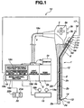
- the treatment instrument apparatus for endoscope 10 includes an endoscopic treatment instrument 11, which is inserted into a target region in a body cavity through an endoscope 1.
- the endoscope 1 includes an insertion portion 2 to be inserted in the body cavity, an operation portion 3 provided on a proximal end side of the insertion portion, and a universal cord 4 extended from the operation portion 3.
- An end portion of the universal cord 4 is connected with an external instrument 5.
- the insertion portion 2 includes, in the following order from a distal end side thereof, a distal end portion 2a, a bending portion 2b which bends in, for example, up/down and left/right directions, and a long flexible tube portion 2c formed of a flexible member.
- the operation portion 3 which serves also as a grasping portion to be grasped by an operator, is provided with a bending knob 3a to be operated to bend the bending portion 2b, and an air/water feeding button 3b and a suction button 3c for feeding air/water and suction from the distal end portion 2a.
- a treatment instrument insertion portion 6 is provided on the insertion portion 2 side of the operation portion 3.
- the distal end portion 2a of insertion portion 2 is provided with an image pickup optical system including a CCD as an image pickup device, an optical lens, and the like; an illumination optical system to irradiate illumination light; a nozzle to clean a surface of the optical lens such as of the image pickup optical system; a forward water feeding hole; a treatment instrument protruding hole; and a treatment instrument raising table.
- the endoscope 1 shown in FIG. 1 is of a side-view type, wherein the image pickup optical system, the illumination optical system, and also the treatment instrument protruding hole are provided on a side surface of the distal end portion 2a.
- the treatment instrument raising table is configured to change lead-out direction of the treatment instrument externally protruded from the treatment instrument protruding hole of the distal end portion 2a, from lateral to upward direction in the drawing.
- a signal cable to transmit a signal to drive the CCD of the image pickup optical system and an image pickup signal
- a light guide cable to lead illumination light to the illumination optical system
- a bending wire joined to the bending portion 2b and the bending knob 3a
- various tubes for feeding water/air and suction and others, and is provided a treatment instrument insertion duct 2d to communicate between a treatment instrument insertion port 6a and a treatment instrument protruding hole 2e provided at the distal end portion 2a.
- the universal cord 4 In through the universal cord 4 are inserted the signal cable, the light guide cable, the various tubes, signal lines extended from the air/water feeding button and the suction button, and so on.
- the end portion of the universal cord 4 is provided with a connector 4a which is detachably attachable to the external instrument 5.
- the external instrument 5 connected with the connector 4a includes a light source apparatus 5a and a video processor 5b.
- the light source apparatus 5a generates illumination light to be supplied to the illumination optical system.
- the video processor 5b supplies a drive signal of the CCD, and generates and records video signals based on image pickup signals from the CCD.
- the video processor 5b is connected to a monitor 5c as the external instrument 5. On a screen of the monitor 5c, an endoscope image or the like is displayed based on the video signal generated at the video processor 5b.
- the light source apparatus 5a incorporates or is attached with an air/water feeding pump and a suction pump.
- the signal lines and the tubes are connected in a predetermined function state.
- the operator inserts the insertion portion 2 of the endoscope 1 into the body cavity, observing an endoscope image displayed on the monitor 5c.
- the endoscopic treatment instrument 11 is inserted into the treatment instrument insertion port 6a, through the treatment instrument insertion duct 2d, to protrude from the treatment instrument protruding hole 2e of the distal end portion 2a.
- the endoscopic treatment instrument 11 includes a tube body 12, pressure sensors 13, a first bending portion 14, a second bending portion 15, an end cap 16, a pressure sensor signal cable 17, and a control unit 18.
- the tube body 12 is a long and hollow tube having a through hole 12a.
- the through hole 12 serves as an insertion path in which are inserted a guide wire (not shown) or a treatment instrument such as a catheter, or as a flow path to supply a fluid such as an X-ray contrast medium.
- the pressure sensors 13 serve as pressure measuring means, and for example four pressure sensors 13 are provided at the distal end part, specifically on a distal end surface, of the tube body 12.
- the first bending portion 14 is provided by a predetermined length in axial direction at the distal end part of the tube body 12.
- the second bending portion 15 is provided by a predetermined length in axial direction on a rear end side of the first bending portion 14.
- the end cap 16 is provided at a proximal end of the tube body 12.
- the signal cable 17 is formed to bundle signal lines (not shown) extended from the pressure sensors 13, the first bending portion 14, and the second bending portion 15. An end portion of the signal cable 17 is connected to the control unit 18.
- the control unit 18 is control means and connected with a joystick apparatus 19 and a foot switch 20.
- the joystick apparatus 19 is bending operation means for independent bending operations of the first bending portion 14 and the second bending portion 15.
- the foot switch 20 is advancing/retreating means to activate an advancing/retreating apparatus 21 for advancing/retreating the tube body 12 of the endoscopic treatment instrument 11.
- the advancing/retreating apparatus 21 is provided to the treatment instrument insertion portion 6 of the operation portion 3 of the endoscope apparatus 1.
- the advancing/retreating apparatus 21 includes a pair of roller 21a, 21b to sandwichingly hold the tube body 12.
- One of the rollers 21a, 21b is forwardly/backwardly rotated by an electric motor not shown. By rotating the electric motor with the tube body 12 sandwichingly held by the pair of rollers 21a, 21b, the tube body 12 is moved to advance/retreat.
- the advancing/retreating apparatus 21 includes an electrode portion 21c to electrically contact a contact portion 6b provided to the treatment instrument insertion portion 6. From the contact portion 6b extends a signal cable 18a.
- the signal cable 18a includes a power line to supply electric power to the electric motor, and a signal line to transmit a control signal to instruct a rotation action.
- the signal cable 18a is inserted in through the operation portion 3 and the universal cord 4, extended to the universal connector 4a, and connected to the control unit 18 via the universal connector 4a.
- the foot switch 20 includes switches 20a, 20b.
- a first switch 20a instructs an advancing action and a second switch 20b instructs a retreating action.
- the switches 20a, 20b outputs a signal to instruct the control unit 18 on a predetermined action.
- a control signal to rotate the roller 21a for example, is outputted from the control unit 18 to the electric motor of the advancing/retreating apparatus 21, so that the tube body 12 is advanced/retreated.
- the tube body 12 of the endoscopic treatment instrument 11 is inserted into the treatment instrument insertion duct 2d via the advancing/retreating apparatus 21 provided to the treatment instrument insertion portion 6 of the operation portion 3 of the endoscope apparatus 1.
- the tube body 12 is moved to advance/retreat along with operation of the foot switch 20.
- the first bending portion 14 and the second bending portion 15 provided at the distal end portion of the tube body 12 configuring the endoscopic treatment instrument 11, which are protruded from the treatment instrument protruding hole 2e of the distal end portion 2a, are activated to bend along with operation of joysticks 19a, 19b of the joystick apparatus 19. From the joystick apparatus 19, a signal to instruct bending action is outputted to the corresponding bending portion 14, 15 via the control unit 18.
- the pressure sensors 13a, 13b, 13c, 13d are for detecting a contact pressure to occur when the distal end surface of tube body 12 contacts a lumen wall when the tube body 12 is inserted into the lumen. That is, the pressure sensors 13a, 13b, 13c, 13d are configured to have a shape and area to detect the pressure to occur when the distal end surface of the tube body 12 contacts the lumen wall or the like.
- the tube body 12 is provided with the first bending portion 14 configured with a length dimension L, and the second bending portion 15 which is provided in a linked manner to the first bending portion 14, having the same length dimension L as with the first bending portion 14.
- the bending portions 14, 15 are each provided with four bending mechanism portions at an interval of about 90 degrees, as shown in FIGS. 3 and 4 .
- the bending mechanism portions are what are known as artificial muscles 14a, 14b, 14c, 14d, 15a, 15b, 15c, 15d, serving as polymeric actuators.
- the first bending portion 14 includes the artificial muscles 14a, 14b, 14c, 14d
- the second bending portion 15 includes the artificial muscles 15a, 15b, 15c, 15d.
- the polymeric actuators are formed such that, when a voltage is applied thereto, positive ions in a polymeric electrolyte move to a cathode side, resulting in swelling of the front and rear lateral portions of the actuators and therefore bending and deformation thereof.
- the artificial muscles 14a, 14b, 14c, 14d, 15a, 15b, 15c, 15d are formed to have a predetermined width dimension h with the length L. Note that the pressure sensors 13a, 13b, 13c, 13d, the artificial muscles 14a, 14b, 14c, 14d, and the artificial muscles 15a, 15b, 15c, 15d are arranged at similar positions as viewed from the front, in other words, in the same phase in a cross sectional direction.
- the strain sensors 21a, 21b, 21c, 21d, 22a, 22b, 22c, 22d having a length dimension shorter than L.
- the strain sensors are bending shape measuring means, which measure bending state of the bending portions 14, 15 in bent state.
- a voltage is applied to each of the artificial muscle 14a and the artificial muscle 14c opposite to the artificial muscle 14a so as to bend the artificial muscles 14a, 14c in the same direction. That is, by adequately controlling a voltage to apply to each of the artificial muscles 14a, 14b, 14c, 14d of the first bending portion 14, the first bending portion 14 can be bent in up/down and left/right directions.
- the second bending portion 15 can also be similarly bent in up/down and left/right directions by adequately controlling a voltage to apply to each of the artificial muscles 15a, 15b, 15c, 15d.
- the strain sensors 21a, 21b, 21c, 21d detect strain that occurs with bending action of the artificial muscles 14a, 14b, 14c, 14d provided to the first bending portion 14.
- the strain sensors 22a, 22b, 22c, 22d detect strain that occurs with bending action of the artificial muscles 15a, 15b, 15c, 15d provided to the second bending portion 15. From the strain detected by these strain sensors 21a to 21d and 22a to 22d, respective curvatures of the bending portions 14, 15 are calculated by a calculation section 18e of the control unit 18 and recorded in a recording section 18d based on the calculation results.
- the signal cable 17 is extended. A proximal end of the signal cable 17 is connected to the control unit 18.
- electric wires 17a, 17b and signal lines 13e, 17c, 17d are contained.
- the electric wire 17a is connected to each of the artificial muscles 14a, 14b, 14c, 14d configuring the first bending portion 14.
- the electric wire 17b is connected to each of the artificial muscles 15a, 15b, 15c, 15d configuring the second bending portion 15.
- These electric wires 17a, 17b supply bending action voltage to activate the bending portions 14, 15 to bend.
- the signal line 13e is connected to each of the pressure sensors 13a, 13b, 13c, 13d.
- the signal line 13e transmits pressure detection signal detected by the pressure sensors 13a, 13b, 13c, 13d.
- the signal line 17c is connected to each of the strain sensors 21a, 21b, 21c, 21d, to transmit a detection value corresponding to the bending state.
- the signal line 17d is connected to each of the strain sensors 22a, 22b, 22c, 22d, to transmit a detection value corresponding to the bending state.
- the control unit 18, the joystick apparatus 19, and the foot switch 20 are operation portions of the treatment instrument apparatus for endoscope 10.
- the joystick apparatus 19 includes a first joystick 19a that outputs an instruction signal to operate to bend the first bending portion 14, and a joystick 19b that outputs an instruction signal to operate to bend the second bending portion 15. Based on difference in the direction of the inclining operation and inclining angle as the operation amount of the joysticks 19a, 19b, the control unit 18 generates a bending action voltage to control bending directions and curvatures of the first bending portion 14 or the second bending portion 15.
- the generated bending action voltage is then applied via the electric wires 17a, 17b to the artificial muscles 14a, 14b, 14c, 14d of the first bending portion 14, or the artificial muscles 15a, 15b, 15c, 15d of the second bending portion 15, to activate the bending portions 14, 15 to bend.
- the foot switch 20 outputs an instruction signal to activate the advancing/retreating apparatus 21 to rotate forward, and an instruction signal to activate the same to rotate backward.
- the control unit 18 When the first switch 20a is operated to turn on, the control unit 18 outputs to the electric motor of the advancing/retreating apparatus 21 a control signal to drive the electric motor to rotate forward, via the signal cable 18a. Then, when the second switch 20a is turned off, the electric motor stops driving.
- the control unit 18 outputs to the electric motor of the advancing/retreating apparatus 21 a control signal to drive the electric motor to rotate backward, via the signal cable 18a. Then, when the first switch 20a is brought into an off state, the electric motor stops driving.
- the control unit 18 includes an advance/retreat control section 18b as advance/retreat control means and a bend control section 18c as bend control means.
- the advance/retreat control section 18b generates a control signal based on the instruction signal from the foot switch 20, while at the same time generates a control signal based on measurement results outputted from the pressure sensors 13a, 13b, 13c, 13d, so as to activate the advancing/retreating apparatus 21 to advance/retreat the tube body 12.
- the advance/retreat control section 18b generates a bending action voltage based on the instruction signal outputted from the joysticks 19a, 19b of the joystick apparatus 19, while at the same time generates a bending action voltage in line with detection values corresponding to the bending state, outputted from the strain gauges 21a to 21d, 22a to 22d, so as to activate the corresponding bending portions 14, 15 to bend in a predetermined direction.
- the tube body 12 of the endoscopic treatment instrument 11 is inserted into the treatment instrument insertion duct 2d of the insertion portion 2 from the treatment instrument insertion port 6a of the operation portion 3 via the advancing/retreating apparatus 21 mounted at the treatment instrument insertion portion 6 of the endoscope apparatus 1. Then, the distal end of the tube body 12 is protruded from the distal end portion 2a of the insertion portion 2. Thereafter, the treatment instrument raising table (not shown) provided to the distal end portion 2a is operated to raise so as to insert the tube body 12 into, for example, the bile duct via the papilla.
- the operator On confirming on the screen that the distal end of the tube body 12 is inserted into the bile duct, the operator operates to turn on the first switch 20a of the foot switch 20. This results in a control signal to be outputted from the control unit 18 to the advancing/retreating apparatus 21, to drive to rotate the electric motor, advancing the tube body 12 toward a deep part of the bile duct.
- control by the control unit 18 starts.
- the control unit 18 obtains pressure values detected by the pressure sensors 13a, 13b, 13c, 13d provided on the distal end surface of the tube body 12 as shown in step S1, then proceeding to step S2.
- the control unit 18 judges whether or not the pressure value obtained from each of the sensors 13a, 13b, 13c, 13d is equal to or smaller than a threshold value, that is, "pressure value of each pressure sensor ⁇ threshold value", while also judging whether or not the pressure values of the pressure sensors 13a, 13b, 13c, 13d are generally the same.
- the threshold value here is a value with a magnitude that prevents damage to the lumen wall. Therefore, even if the pressure value has reached the threshold value, the bile duct wall or the like is not damaged by advancing of the tube body 12 in contact with the lumen wall.
- step S2 when the tube body 12 is smoothly advancing in a straight part of the bile duct, the pressure sensors 13a, 13b, 13c, 13d provide pressure values that are generally the same and smaller than the threshold value.
- the pressure sensors 13a, 13b, 13c, 13d when the tube body 12 is advancing in a curving part of the bile duct, at least a part of the distal end surface of the tube body 12 contacts with the curving bile duct wall.
- the pressure sensor 13a in contact with the bile duct wall has a detected pressure value that is higher than detected pressure values of the other pressure sensors 13b, 13c, 13d.
- the control unit 18 causes the control unit 18 to judge that the side having the pressure sensor 13a on the distal end surface is in contact with the lumen wall.
- step S2 if the respective pressure values detected by the pressure sensors 13a, 13b, 13c, 13d are equal to or smaller than the threshold value, the control unit 18 judges that the distal end surface of the tube body 12 is not in contact with the bile duct wall, and proceeds to step S4.
- step S4 the control unit 18 outputs, from the advance/retreat control section 18b to the advancing/retreating apparatus 21, a control signal to drive to rotate forward the advancing/retreating apparatus 21, and obtains detection values of the strain sensors 21a, 21b, 21c, 21d provided to the first bending portion 14, to calculate a curvature Rn by means of the calculation section 18e.
- step S5 the control unit 18 makes addition of ⁇ ln which is the advance amount of the tube body 12, and judges whether or not the resulting addition is equal to or smaller than the entire length L in the axial direction of the first bending portion 14.
- step S5 if the resulting addition of ⁇ ln is judged to be equal to or smaller than the entire length L of the first bending portion 14, the processing proceeds to step S1.
- the control unit 18 activates the first bending portion 14 to bend in the direction opposite to that of the setting position of, for example, the pressure sensor 13a that has detected a pressure greater than the threshold value in the step S3, and then returns to step S1 again.
- step S6 the control unit 18 extracts from the recording section 18d data of the curvature Rn in the advancing by ⁇ ln of the first bending portion 14, thereafter continuing the advancing and insertion of the tube body 12.
- the bending operation of the joystick 19b of the joystick apparatus 19 is performed based on the data of the curvature Rn in the advancing by ⁇ ln of the first bending portion 14, extracted in the control unit 18.
- the second bending portion 15 is bend-controlled based on the data recorded in the recording section 18d by the control unit 18. This results in that the second bending portion 15 traces the path on which the first bending portion 14 advanced, which allows efficiently and smoothly performing the bending action of the second bending portion 15.
- the plurality of pressure sensors 13a, 13b, 13c, 13d are provided on the distal end surface of the tube body 12 to be inserted in the lumen, and in addition, the first bending portion 14 including the artificial muscles 14a, 14b, 14c, 14d adjacently provided in the axial direction of the tube body 12, and the second bending portion 15 including the artificial muscles 15a, 15b, 15c, 15d are respectively provided with the strain sensors 21a to 21d and the strain sensors 22a to 22d for detecting the respective curvatures of the bending portions 14, 15. Therefore, it is made possible to quickly and smoothly perform the insertion operation into the complicatedly bent lumen without damaging the lumen wall by the advance of the tube body 12.
- the artificial muscles 14a, 14c of the bending portion 14 and the artificial muscle 15a, 15c of the bending portions 15 are operated to be contract simultaneously. This allows the bending operation in the upward direction to be performed more quickly. Note that, also in other directions, similar working and effect can be obtained by simultaneouly operating the artificial muscles in the same phase.
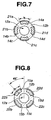
- FIGS. 7 and 8 In the case of performing a bending operation in the same diagonal direction as above using the arrangement of the artificial muscles shown in FIGS. 3 and 4 , a total of four artificial muscles are controlled: the artificial muscles 14a, 14d of the first bending portion 14 and the artificial muscles 15a, 15d of the second bending portion 15. Therefore, the configuration in FIGS. 7 and 8 can better reduce the load on the control circuit provided in the control unit 18.
- the above embodiment of the present invention has described an exemplary configuration in which the first bending portion 14 and the second bending portion 15 are respectively provided with four artificial muscles 14a, 14b, 14c, 14d and 15a, 15b, 15c, 15d, at an interval of 90 degrees.
- the interval of providing the artificial muscles is not limited to 90 degrees, that is, four intervals.
- three artificial muscle may be provided at an interval of 120 degrees, or two artificial muscles may be provided at an interval of 180 degrees. That is, the artificial muscles may be arranged in any manner to allow the distal end part of the tube body 12 to bend in up/down direction or left/right
- the bending mechanism portions of the first bending portion 14 and the second bending portion 15 employ artificial muscles, i.e., polymeric actuators.
- the bending mechanism portion is not limited to the artificial muscle, but may be one configured by a shape-memory alloy to perform a bending action, or actuators not needing cooling means such as an air pressure actuator to be activated to bend by air pressure, or a wire-driven actuator to be activated to bend by a pulling wire.
- the pressure sensors 13a, 13b, 13c, 13d may be arranged on a tapered surface of, for example, 45 degrees provided on the end surface of the tube body 12.
Abstract
Description
- The present invention relates to an endoscopic treatment instrument to be inserted into a lumen in a body cavity through an endoscope, allowing for insertion operation adapted to running shape of the lumen, and to a treatment instrument apparatus for endoscope including the endoscopic treatment instrument.
- Conventionally, intra-body-cavity observations have been performed by inserting an endoscope into a body cavity, or various treatments by inserting various treatment instruments into the body cavity through a treatment instrument insertion duct provided in the endoscope.
- For example, in performing a treatment checking the complicated running shapes of bile duct and pancreatic duct with contrast medium agent administered into the bile duct and pancreatic duct from duodenum papilla, the treatment instrument is protruded from a side surface at a distal end portion of an endoscope insertion portion inserted into the duodenum. At this time, an operator needs to perform insertion operation of the treatment instrument by orienting the treatment instrument in a direction to look up at the papilla through an observation window provided to the endoscope insertion portion.
- To this end, at the distal end portion of the endoscope insertion portion, a raising table is provided to change the lead-out direction of the treatment instrument, i.e., to lead out the treatment instrument in the papilla direction. By adjusting raising angle of the raising table, the operator inserts the treatment instrument from the papilla into the bile duct or pancreatic duct.
- Japanese unexamined patent publication No.
6-63004 - In other words, in the medical tube, shrinking and extending characteristics of the shape-memory alloy wire are used to bend the first multihole tube in two directions, so as to insert the medical tube along the shape of the bile duct and the pancreatic duct.
- However, in the medical tube proposed in Japanese unexamined patent publication No.
6-63004 - That is, it is desired to decrease the outer diameter of a treatment instrument to be inserted along the complicated running shape of the bile duct and the pancreatic duct.
- Document
US 2002/0058858 A1 concerns an endoscope having at its distal end a bending portion consisting of a first bending portion and a second bending portion. Angling knobs are connected to first and second wires extending to the first and second bending portions for selectively bending the first and second bending portions. - Document
US 2003/0149338 A1 concerns a positioning, intervention and/or exploration device having two end pieces and at least one cable extending from one end piece to the other. The device further comprises in two groups arranged bellows, each directly fixed to both of the end pieces, and means for independently modifying the pressure of a fluid provided in each of the bellows. - Document
DE 37 07 787 A1 concerns a bendable endoscope having chambers in which an easily evaporating liquid can be individually heated by heating means provided in the chambers. Depending on the amount of heating applied to the chambers, the endoscope can be bent and/or elongated. - Document
US 5,897,488 concerns a bending insertion instrument comprising a bending portion, three angle wires arranged in the bending portion, three artificial rubber muscles for independently operating the three angle wires, and control means for arbitrarily controlling operating amounts of the three angle wires through the three artificial rubber muscles. - Document
US 6,770,027 concerns a robotic endoscope with the features of the preamble ofindependent claim 1. - The present invention has been made in view of the above circumstances, and an object of the present invention is to provide an endoscopic treatment instrument which has a small outer diameter and can facilitate insertion operation into a lumen with complicated running shape, and a treatment instrument apparatus for endoscope.
- An endoscopic treatment instrument of the present invention includes the features of
claim 1. An endoscope treatment instrument comprises a long tube body to be inserted into a body cavity, including a flexible member; a first bending portion provided to a distal end part of the tube body, for bending the tube body with respect to an axial direction; a second bending portion provided in a linked manner to a proximal end side of the first bending portion, for bending the tube body in the axial direction; and a bending operation portion for independently bending the first and second bending portions. -
-
FIG. 1 is a view illustrating a configuration of a treatment instrument apparatus for endoscope configured by an endoscopic treatment instrument and an endoscope. -
FIG. 2 is a partial sectional view showing a configuration of a distal end portion of the endoscopic treatment instrument. -
FIG. 3 is a sectional view of A-A line ofFIG. 2 . -
FIG. 4 is a sectional view of B-B line ofFIG. 2 . -
FIG. 5 is a front view showing a configuration of a distal end surface of the endoscopic treatment instrument ofFIG. 2 as viewed from an arrow C direction. -
FIG. 6 is a flow chart illustrating an exemplary control action during insertion operation of the treatment instrument apparatus for endoscope. -
FIG. 7 is a sectional view illustrating arrangement positions of artificial muscles having strain sensors of a first bending portion, in a configuration in which artificial muscles having strain sensors are arranged with 45-degree phase between the first bending portion and a second bending portion. -
FIG. 8 is a sectional view illustrating arrangement positions of artificial muscles having strain sensors of the second bending portion, in a configuration in which artificial muscles having strain sensors are arranged with 45-degree phase between the first and second bending portions. - Referring to the drawings, an embodiment of the present invention is described in detail below.
- Using
FIG. 1 , a treatment instrument apparatus forendoscope 10 of the embodiment of the present invention is described. The treatment instrument apparatus forendoscope 10 includes anendoscopic treatment instrument 11, which is inserted into a target region in a body cavity through anendoscope 1. - The
endoscope 1 includes aninsertion portion 2 to be inserted in the body cavity, anoperation portion 3 provided on a proximal end side of the insertion portion, and auniversal cord 4 extended from theoperation portion 3. An end portion of theuniversal cord 4 is connected with an external instrument 5. Theinsertion portion 2 includes, in the following order from a distal end side thereof, adistal end portion 2a, abending portion 2b which bends in, for example, up/down and left/right directions, and a longflexible tube portion 2c formed of a flexible member. Theoperation portion 3, which serves also as a grasping portion to be grasped by an operator, is provided with abending knob 3a to be operated to bend thebending portion 2b, and an air/water feeding button 3b and asuction button 3c for feeding air/water and suction from thedistal end portion 2a. On theinsertion portion 2 side of theoperation portion 3, a treatmentinstrument insertion portion 6 is provided. - Though not shown, the
distal end portion 2a ofinsertion portion 2 is provided with an image pickup optical system including a CCD as an image pickup device, an optical lens, and the like; an illumination optical system to irradiate illumination light; a nozzle to clean a surface of the optical lens such as of the image pickup optical system; a forward water feeding hole; a treatment instrument protruding hole; and a treatment instrument raising table. Note that theendoscope 1 shown inFIG. 1 is of a side-view type, wherein the image pickup optical system, the illumination optical system, and also the treatment instrument protruding hole are provided on a side surface of thedistal end portion 2a. The treatment instrument raising table is configured to change lead-out direction of the treatment instrument externally protruded from the treatment instrument protruding hole of thedistal end portion 2a, from lateral to upward direction in the drawing. - Though not shown, in the
flexible tube portion 2c of theinsertion portion 2, there are inserted a signal cable to transmit a signal to drive the CCD of the image pickup optical system and an image pickup signal; a light guide cable to lead illumination light to the illumination optical system; a bending wire joined to thebending portion 2b and thebending knob 3a; various tubes for feeding water/air and suction; and others, and is provided a treatment instrument insertion duct 2d to communicate between a treatmentinstrument insertion port 6a and a treatmentinstrument protruding hole 2e provided at thedistal end portion 2a. - In through the
universal cord 4 are inserted the signal cable, the light guide cable, the various tubes, signal lines extended from the air/water feeding button and the suction button, and so on. The end portion of theuniversal cord 4 is provided with aconnector 4a which is detachably attachable to the external instrument 5. - The external instrument 5 connected with the
connector 4a includes alight source apparatus 5a and a video processor 5b. Thelight source apparatus 5a generates illumination light to be supplied to the illumination optical system. The video processor 5b supplies a drive signal of the CCD, and generates and records video signals based on image pickup signals from the CCD. The video processor 5b is connected to amonitor 5c as the external instrument 5. On a screen of themonitor 5c, an endoscope image or the like is displayed based on the video signal generated at the video processor 5b. Note that thelight source apparatus 5a incorporates or is attached with an air/water feeding pump and a suction pump. - By connecting the
universal connector 4a of theuniversal cord 4 to each of theinstruments 5a, 5b, the signal lines and the tubes are connected in a predetermined function state. - The operator inserts the
insertion portion 2 of theendoscope 1 into the body cavity, observing an endoscope image displayed on themonitor 5c. After thedistal end portion 2a of theinsertion portion 2 is inserted to near the target region in the body cavity, theendoscopic treatment instrument 11 is inserted into the treatmentinstrument insertion port 6a, through the treatment instrument insertion duct 2d, to protrude from the treatmentinstrument protruding hole 2e of thedistal end portion 2a. - Here, the
endoscopic treatment instrument 11 of the present invention is described. - The
endoscopic treatment instrument 11 includes atube body 12,pressure sensors 13, afirst bending portion 14, asecond bending portion 15, an end cap 16, a pressuresensor signal cable 17, and acontrol unit 18. Thetube body 12 is a long and hollow tube having a throughhole 12a. The throughhole 12 serves as an insertion path in which are inserted a guide wire (not shown) or a treatment instrument such as a catheter, or as a flow path to supply a fluid such as an X-ray contrast medium. Thepressure sensors 13 serve as pressure measuring means, and for example fourpressure sensors 13 are provided at the distal end part, specifically on a distal end surface, of thetube body 12. Thefirst bending portion 14 is provided by a predetermined length in axial direction at the distal end part of thetube body 12. Thesecond bending portion 15 is provided by a predetermined length in axial direction on a rear end side of thefirst bending portion 14. The end cap 16 is provided at a proximal end of thetube body 12. Thesignal cable 17 is formed to bundle signal lines (not shown) extended from thepressure sensors 13, thefirst bending portion 14, and thesecond bending portion 15. An end portion of thesignal cable 17 is connected to thecontrol unit 18. - The
control unit 18 is control means and connected with ajoystick apparatus 19 and afoot switch 20. Thejoystick apparatus 19 is bending operation means for independent bending operations of thefirst bending portion 14 and thesecond bending portion 15. Thefoot switch 20 is advancing/retreating means to activate an advancing/retreatingapparatus 21 for advancing/retreating thetube body 12 of theendoscopic treatment instrument 11. - The advancing/retreating
apparatus 21 is provided to the treatmentinstrument insertion portion 6 of theoperation portion 3 of theendoscope apparatus 1. The advancing/retreatingapparatus 21 includes a pair ofroller tube body 12. One of therollers tube body 12 sandwichingly held by the pair ofrollers tube body 12 is moved to advance/retreat. The advancing/retreatingapparatus 21 includes anelectrode portion 21c to electrically contact acontact portion 6b provided to the treatmentinstrument insertion portion 6. From thecontact portion 6b extends asignal cable 18a. Thesignal cable 18a includes a power line to supply electric power to the electric motor, and a signal line to transmit a control signal to instruct a rotation action. Thesignal cable 18a is inserted in through theoperation portion 3 and theuniversal cord 4, extended to theuniversal connector 4a, and connected to thecontrol unit 18 via theuniversal connector 4a. Thefoot switch 20 includesswitches first switch 20a instructs an advancing action and asecond switch 20b instructs a retreating action. When operated by the operator, theswitches control unit 18 on a predetermined action. Thereafter, a control signal to rotate theroller 21a, for example, is outputted from thecontrol unit 18 to the electric motor of the advancing/retreatingapparatus 21, so that thetube body 12 is advanced/retreated. - The
tube body 12 of theendoscopic treatment instrument 11 is inserted into the treatment instrument insertion duct 2d via the advancing/retreatingapparatus 21 provided to the treatmentinstrument insertion portion 6 of theoperation portion 3 of theendoscope apparatus 1. Thetube body 12 is moved to advance/retreat along with operation of thefoot switch 20. Thefirst bending portion 14 and thesecond bending portion 15 provided at the distal end portion of thetube body 12 configuring theendoscopic treatment instrument 11, which are protruded from the treatmentinstrument protruding hole 2e of thedistal end portion 2a, are activated to bend along with operation ofjoysticks joystick apparatus 19. From thejoystick apparatus 19, a signal to instruct bending action is outputted to the corresponding bendingportion control unit 18. - Referring to
FIGS. 2 to 6 , thepressure sensors 13, thefirst bending portion 14, and thesecond bending portion 15 of theendoscopic treatment instrument 11 are described. - On a distal end surface of a
substance portion 12b of thetube body 12, for example, fourpressure sensors FIGS. 2 and5 . Thepressure sensors tube body 12 contacts a lumen wall when thetube body 12 is inserted into the lumen. That is, thepressure sensors tube body 12 contacts the lumen wall or the like. - The
tube body 12 is provided with thefirst bending portion 14 configured with a length dimension L, and thesecond bending portion 15 which is provided in a linked manner to thefirst bending portion 14, having the same length dimension L as with thefirst bending portion 14. The bendingportions FIGS. 3 and 4 . The bending mechanism portions are what are known asartificial muscles first bending portion 14 includes theartificial muscles second bending portion 15 includes theartificial muscles artificial muscles pressure sensors artificial muscles artificial muscles - On outer surfaces of the
artificial muscles first bending portion 14 and thesecond bending portion 15, there are respectively provided thestrain sensors portions - To bend to deform the
first bending portion 14 in, for example, upward direction in the drawing, a voltage is applied to each of theartificial muscle 14a and theartificial muscle 14c opposite to theartificial muscle 14a so as to bend theartificial muscles artificial muscles first bending portion 14, thefirst bending portion 14 can be bent in up/down and left/right directions. Note that thesecond bending portion 15 can also be similarly bent in up/down and left/right directions by adequately controlling a voltage to apply to each of theartificial muscles - The
strain sensors artificial muscles first bending portion 14. On the other hand, thestrain sensors artificial muscles second bending portion 15. From the strain detected by thesestrain sensors 21a to 21d and 22a to 22d, respective curvatures of the bendingportions calculation section 18e of thecontrol unit 18 and recorded in arecording section 18d based on the calculation results. - From the end cap 16 side of the
tube body 12, thesignal cable 17 is extended. A proximal end of thesignal cable 17 is connected to thecontrol unit 18. In thesignal cable 17,electric wires signal lines electric wire 17a is connected to each of theartificial muscles first bending portion 14. Theelectric wire 17b is connected to each of theartificial muscles second bending portion 15. Theseelectric wires portions - In contrast thereto, the
signal line 13e is connected to each of thepressure sensors signal line 13e transmits pressure detection signal detected by thepressure sensors signal line 17c is connected to each of thestrain sensors signal line 17d is connected to each of thestrain sensors - The
control unit 18, thejoystick apparatus 19, and thefoot switch 20 are operation portions of the treatment instrument apparatus forendoscope 10. Thejoystick apparatus 19 includes afirst joystick 19a that outputs an instruction signal to operate to bend thefirst bending portion 14, and ajoystick 19b that outputs an instruction signal to operate to bend thesecond bending portion 15. Based on difference in the direction of the inclining operation and inclining angle as the operation amount of thejoysticks control unit 18 generates a bending action voltage to control bending directions and curvatures of thefirst bending portion 14 or thesecond bending portion 15. The generated bending action voltage is then applied via theelectric wires artificial muscles first bending portion 14, or theartificial muscles second bending portion 15, to activate the bendingportions - The
foot switch 20 outputs an instruction signal to activate the advancing/retreatingapparatus 21 to rotate forward, and an instruction signal to activate the same to rotate backward. When thefirst switch 20a is operated to turn on, thecontrol unit 18 outputs to the electric motor of the advancing/retreatingapparatus 21 a control signal to drive the electric motor to rotate forward, via thesignal cable 18a. Then, when thesecond switch 20a is turned off, the electric motor stops driving. On the other hand, when thesecond switch 20b is operated to turn on, thecontrol unit 18 outputs to the electric motor of the advancing/retreatingapparatus 21 a control signal to drive the electric motor to rotate backward, via thesignal cable 18a. Then, when thefirst switch 20a is brought into an off state, the electric motor stops driving. - The
control unit 18 includes an advance/retreat control section 18b as advance/retreat control means and abend control section 18c as bend control means. As mentioned above, the advance/retreat control section 18b generates a control signal based on the instruction signal from thefoot switch 20, while at the same time generates a control signal based on measurement results outputted from thepressure sensors apparatus 21 to advance/retreat thetube body 12. On the other hand, the advance/retreat control section 18b generates a bending action voltage based on the instruction signal outputted from thejoysticks joystick apparatus 19, while at the same time generates a bending action voltage in line with detection values corresponding to the bending state, outputted from thestrain gauges 21a to 21d, 22a to 22d, so as to activate thecorresponding bending portions - Referring to
FIG. 6 , there is described an exemplary control by the advance/retreat control section 18b and thebend control section 18c of thecontrol unit 18. - First, the
tube body 12 of theendoscopic treatment instrument 11 is inserted into the treatment instrument insertion duct 2d of theinsertion portion 2 from the treatmentinstrument insertion port 6a of theoperation portion 3 via the advancing/retreatingapparatus 21 mounted at the treatmentinstrument insertion portion 6 of theendoscope apparatus 1. Then, the distal end of thetube body 12 is protruded from thedistal end portion 2a of theinsertion portion 2. Thereafter, the treatment instrument raising table (not shown) provided to thedistal end portion 2a is operated to raise so as to insert thetube body 12 into, for example, the bile duct via the papilla. On confirming on the screen that the distal end of thetube body 12 is inserted into the bile duct, the operator operates to turn on thefirst switch 20a of thefoot switch 20. This results in a control signal to be outputted from thecontrol unit 18 to the advancing/retreatingapparatus 21, to drive to rotate the electric motor, advancing thetube body 12 toward a deep part of the bile duct. - As the advancing/retreating
apparatus 21 is driven to start advancing thetube body 12, control by thecontrol unit 18 starts. In other words, thecontrol unit 18 obtains pressure values detected by thepressure sensors tube body 12 as shown in step S1, then proceeding to step S2. In step S2, by means of thecalculation section 18e, thecontrol unit 18 judges whether or not the pressure value obtained from each of thesensors pressure sensors - Note that the threshold value here is a value with a magnitude that prevents damage to the lumen wall. Therefore, even if the pressure value has reached the threshold value, the bile duct wall or the like is not damaged by advancing of the
tube body 12 in contact with the lumen wall. - In step S2, when the
tube body 12 is smoothly advancing in a straight part of the bile duct, thepressure sensors tube body 12 is advancing in a curving part of the bile duct, at least a part of the distal end surface of thetube body 12 contacts with the curving bile duct wall. This results in that, among thepressure sensors pressure sensor 13a in contact with the bile duct wall has a detected pressure value that is higher than detected pressure values of theother pressure sensors control unit 18 to judge that the side having thepressure sensor 13a on the distal end surface is in contact with the lumen wall. - The
control unit 18 thus compares the pressure values detected by thepressure sensors tube body 12 is in contact with the bile duct wall or the like. - In the step S2, if the respective pressure values detected by the
pressure sensors control unit 18 judges that the distal end surface of thetube body 12 is not in contact with the bile duct wall, and proceeds to step S4. In step S4, thecontrol unit 18 outputs, from the advance/retreat control section 18b to the advancing/retreatingapparatus 21, a control signal to drive to rotate forward the advancing/retreatingapparatus 21, and obtains detection values of thestrain sensors first bending portion 14, to calculate a curvature Rn by means of thecalculation section 18e. That is, the output of the control signal to drive to rotate forward the advancing/retreatingapparatus 21 makes thetube body 12 advance by Δln. For each advance by the distance Δln of thetube body 12, thecontrol unit 18 obtains a detection value of each of thestrain sensors first bending portion 14, so as to calculate the curvature Rn of thefirst bending portion 14 from the strain amount. - Then, as shown in step S5, the
control unit 18 makes addition of Δln which is the advance amount of thetube body 12, and judges whether or not the resulting addition is equal to or smaller than the entire length L in the axial direction of thefirst bending portion 14. In this step S5, if the resulting addition of Δln is judged to be equal to or smaller than the entire length L of thefirst bending portion 14, the processing proceeds to step S1. - On the other hand, if the
control unit 18 detects, in step S2, a pressure greater than the threshold value of any of thepressure sensors control unit 18 proceeds to step S3. In step S3, thecontrol unit 18 performs control to cause the screen to display position of, for example, thepressure sensor 13a that has detected a pressure greater than the threshold value; cause the screen to display a bending direction opposite to that of the position of thepressure sensor 13a; prompt an operation of thejoystick 19a of thejoystick apparatus 19; and apply a bending action voltage to theartificial muscles first bending portion 14 in the direction opposite to that of the position of thepressure sensor 13a. At this time, thefirst bending portion 14 is to be bent by half a diameter d of thetube body 12 shown inFIG. 2 . - The
control unit 18 activates thefirst bending portion 14 to bend in the direction opposite to that of the setting position of, for example, thepressure sensor 13a that has detected a pressure greater than the threshold value in the step S3, and then returns to step S1 again. - Meanwhile, if the
control unit 18 judges, in the step S5, that a resulting addition value of the advance by Δln of thetube body 12 is greater than the entire length L of thefirst bending portion 14, then proceeds to step S6. In step S6, thecontrol unit 18 extracts from therecording section 18d data of the curvature Rn in the advancing by Δln of thefirst bending portion 14, thereafter continuing the advancing and insertion of thetube body 12. The bending operation of thejoystick 19b of thejoystick apparatus 19 is performed based on the data of the curvature Rn in the advancing by Δln of thefirst bending portion 14, extracted in thecontrol unit 18. Thus, thesecond bending portion 15 is bend-controlled based on the data recorded in therecording section 18d by thecontrol unit 18. This results in that thesecond bending portion 15 traces the path on which thefirst bending portion 14 advanced, which allows efficiently and smoothly performing the bending action of thesecond bending portion 15. - As described above, in the
endoscopic treatment instrument 11 of the embodiment of the present invention, the plurality ofpressure sensors tube body 12 to be inserted in the lumen, and in addition, thefirst bending portion 14 including theartificial muscles tube body 12, and thesecond bending portion 15 including theartificial muscles strain sensors 21a to 21d and thestrain sensors 22a to 22d for detecting the respective curvatures of the bendingportions tube body 12. - Note that, as shown in
FIGS. 2 to 4 , theartificial muscles first bending portion 14 and thestrain sensors artificial muscles artificial muscles second bending portion 15 and thestrain sensors strain sensors artificial muscles portion 14 and theartificial muscle portions 15 are operated to be contract simultaneously. This allows the bending operation in the upward direction to be performed more quickly. Note that, also in other directions, similar working and effect can be obtained by simultaneouly operating the artificial muscles in the same phase. - Meanwhile, the
artificial muscles first bending portion 14 and thestrain sensors artificial muscles FIG. 7 , and theartificial muscle second bending portion 15 and thestrain sensors artificial muscle FIG. 8 , may be arranged in a manner shifted by, for example, 45 degrees, i.e., in a changed phase in a cross section. With such arrangement employed, when performing a bending operation in, for example, upper-right diagonal direction inFIG. 7 , theartificial muscles first bending portion 14 are simultaneously contracted, while contracting theartificial muscle 15d of thesecond bending portion 15. By thus controlling the three artificial muscles, bending operation in a diagonal direction can be realized. - In the case of performing a bending operation in the same diagonal direction as above using the arrangement of the artificial muscles shown in
FIGS. 3 and 4 , a total of four artificial muscles are controlled: theartificial muscles first bending portion 14 and theartificial muscles second bending portion 15. Therefore, the configuration inFIGS. 7 and 8 can better reduce the load on the control circuit provided in thecontrol unit 18. - The above embodiment of the present invention has described an exemplary configuration in which the
first bending portion 14 and thesecond bending portion 15 are respectively provided with fourartificial muscles tube body 12 to bend in up/down direction or left/right - direction.
- Further, the bending mechanism portions of the
first bending portion 14 and thesecond bending portion 15 employ artificial muscles, i.e., polymeric actuators. The bending mechanism portion, however, is not limited to the artificial muscle, but may be one configured by a shape-memory alloy to perform a bending action, or actuators not needing cooling means such as an air pressure actuator to be activated to bend by air pressure, or a wire-driven actuator to be activated to bend by a pulling wire. - Furthermore, the
pressure sensors tube body 12. - Thus, it is possible to select an optimum artificial muscle arrangement for use purpose, bending frequency in any bending direction, or the like, of the
tube body 12 - Note that the present invention is not limited only to the above-mentioned embodiment, but may be modified and embodied in various forms without departing from the scope of the present invention.
Claims (4)
- An endoscopic treatment instrument (11), comprising:a long tube body (12) to be inserted into a body cavity, including a flexible member (2c);a first bending portion (14) provided to a distal end part of the tube body (12), for bending the tube body (12) with respect to an axial direction of the tube body (12), the first bending portion (14) being bendable in at least one of an up/down direction and a left/right direction;a second bending portion (15) provided in a linked manner to a proximal end side of the first bending portion (14), for bending the tube body (12) in the axial direction, the second bending portion (15) being bendable in at least one of an up/down direction and a left/right direction;bending operation means (19) for independently bending the first (14) and second (15) bending portions;bend control means (18c);first artificial muscles (14a, 14b, 14c, 14d) provided at the first bending portion (14) and arranged around a central axis of the tube body (12) at angles of equal intervals with respect to the circumferential direction of the tube body (12); and,second artificial muscles (15a, 15b, 15c, 15d) provided at the second bending portion (15) and arranged around the central axis of the tube body (12) at angles of equal intervals with respect to the circumferential direction of the tube body (12), wherein each of the first and second artificial muscles (14a, 14b, 14c, 14d, 15a, 15b, 15c, 15d) has a length L in the axial direction,characterized byfirst strain sensors (21a, 21b, 21c, 21d), wherein each first artificial muscle (14a, 14b, 14c, 14d) has a first strain sensor (21a, 21b, 21c, 21d) provided on its outer surface,second strain sensors (22a, 22b, 22c, 22d), wherein each second artificial muscle (15a, 15b, 15c, 15d) has a second strain sensor (22a, 22b, 22c, 22d) provided on its outer surface, whereinthe first and second strain sensors (21a, 21b, 21c, 21d, 22a, 22b, 22c, 22d) have a length dimension shorter than L, andthe bend control means (18c) are adapted to output a control signal to bend the first (14a, 14b, 14c, 14d) and second (15a, 15b, 15c, 15d) artificial muscles based on measurement results of the first (21a, 21b, 21c, 21d) and second (22a, 22b, 22c, 22d) strain sensors.
- The endoscopic treatment instrument according to Claim 1, wherein the first (14a, 14b, 14c, 14d) and second (15a, 15b, 15c, 15d) artificial muscles are arranged at equal intervals of one of 90-degree intervals, 120-degree intervals, or 180-degree intervals.
- The endoscopic treatment instrument according to Claim 2, wherein the first (14a, 14b, 14c, 14d) and second (15a, 15b, 15c, 15d) artificial muscles are arranged in the same phase in a cross section.
- The endoscopic treatment instrument according to Claim 2, wherein the first (14a, 14b, 14c, 14d) and second (15a, 15b, 15c, 15d) artificial muscles are arranged in different phases in a cross section.
Priority Applications (1)
| Application Number | Priority Date | Filing Date | Title |
|---|---|---|---|
| EP10015160A EP2289591A3 (en) | 2005-06-14 | 2006-06-12 | Endoscope treatment instrument and treatment instrument apparatus for endoscope |
Applications Claiming Priority (2)
| Application Number | Priority Date | Filing Date | Title |
|---|---|---|---|
| JP2005174058 | 2005-06-14 | ||
| PCT/JP2006/311771 WO2006134881A1 (en) | 2005-06-14 | 2006-06-12 | Endoscope treating instrument and endoscope treating instrument device |
Related Child Applications (1)
| Application Number | Title | Priority Date | Filing Date |
|---|---|---|---|
| EP10015160.4 Division-Into | 2010-11-30 |
Publications (3)
| Publication Number | Publication Date |
|---|---|
| EP1892009A1 EP1892009A1 (en) | 2008-02-27 |
| EP1892009A4 EP1892009A4 (en) | 2009-05-27 |
| EP1892009B1 true EP1892009B1 (en) | 2011-12-21 |
Family
ID=37532243
Family Applications (2)
| Application Number | Title | Priority Date | Filing Date |
|---|---|---|---|
| EP06757256A Expired - Fee Related EP1892009B1 (en) | 2005-06-14 | 2006-06-12 | Endoscope treatment instrument |
| EP10015160A Withdrawn EP2289591A3 (en) | 2005-06-14 | 2006-06-12 | Endoscope treatment instrument and treatment instrument apparatus for endoscope |
Family Applications After (1)
| Application Number | Title | Priority Date | Filing Date |
|---|---|---|---|
| EP10015160A Withdrawn EP2289591A3 (en) | 2005-06-14 | 2006-06-12 | Endoscope treatment instrument and treatment instrument apparatus for endoscope |
Country Status (5)
| Country | Link |
|---|---|
| US (1) | US20080097159A1 (en) |
| EP (2) | EP1892009B1 (en) |
| JP (1) | JP5000503B2 (en) |
| CN (1) | CN101198370B (en) |
| WO (1) | WO2006134881A1 (en) |
Families Citing this family (85)
| Publication number | Priority date | Publication date | Assignee | Title |
|---|---|---|---|---|
| US8882657B2 (en) | 2003-03-07 | 2014-11-11 | Intuitive Surgical Operations, Inc. | Instrument having radio frequency identification systems and methods for use |
| US20040199052A1 (en) | 2003-04-01 | 2004-10-07 | Scimed Life Systems, Inc. | Endoscopic imaging system |
| US7922654B2 (en) | 2004-08-09 | 2011-04-12 | Boston Scientific Scimed, Inc. | Fiber optic imaging catheter |
| US11819192B2 (en) | 2004-03-23 | 2023-11-21 | Boston Scientific Scimed, Inc. | In-vivo visualization system |
| ES2409160T3 (en) | 2004-03-23 | 2013-06-25 | Boston Scientific Limited | Live View System |
| US20060252993A1 (en) * | 2005-03-23 | 2006-11-09 | Freed David I | Medical devices and systems |
| EP1956962B1 (en) | 2005-11-22 | 2020-09-16 | Intuitive Surgical Operations, Inc. | System for determining the shape of a bendable instrument |
| GB2435689B (en) * | 2006-03-02 | 2009-04-08 | Insensys Ltd | Structural monitoring |
| US8568299B2 (en) | 2006-05-19 | 2013-10-29 | Intuitive Surgical Operations, Inc. | Methods and apparatus for displaying three-dimensional orientation of a steerable distal tip of an endoscope |
| WO2008094949A2 (en) | 2007-01-29 | 2008-08-07 | Neoguide Systems, Inc. | System for controlling an instrument using shape sensors |
| US7655004B2 (en) | 2007-02-15 | 2010-02-02 | Ethicon Endo-Surgery, Inc. | Electroporation ablation apparatus, system, and method |
| US20080216840A1 (en) * | 2007-03-06 | 2008-09-11 | Searete Llc, A Limited Liability Corporation Of The State Of Delaware | Imaging via the airway |
| US8262655B2 (en) | 2007-11-21 | 2012-09-11 | Ethicon Endo-Surgery, Inc. | Bipolar forceps |
| US8568410B2 (en) | 2007-08-31 | 2013-10-29 | Ethicon Endo-Surgery, Inc. | Electrical ablation surgical instruments |
| US8579897B2 (en) | 2007-11-21 | 2013-11-12 | Ethicon Endo-Surgery, Inc. | Bipolar forceps |
| US9220398B2 (en) | 2007-10-11 | 2015-12-29 | Intuitive Surgical Operations, Inc. | System for managing Bowden cables in articulating instruments |
| US20090112059A1 (en) | 2007-10-31 | 2009-04-30 | Nobis Rudolph H | Apparatus and methods for closing a gastrotomy |
| US8480657B2 (en) * | 2007-10-31 | 2013-07-09 | Ethicon Endo-Surgery, Inc. | Detachable distal overtube section and methods for forming a sealable opening in the wall of an organ |
| US8182418B2 (en) | 2008-02-25 | 2012-05-22 | Intuitive Surgical Operations, Inc. | Systems and methods for articulating an elongate body |
| US8262680B2 (en) | 2008-03-10 | 2012-09-11 | Ethicon Endo-Surgery, Inc. | Anastomotic device |
| US8679003B2 (en) | 2008-05-30 | 2014-03-25 | Ethicon Endo-Surgery, Inc. | Surgical device and endoscope including same |
| US8771260B2 (en) | 2008-05-30 | 2014-07-08 | Ethicon Endo-Surgery, Inc. | Actuating and articulating surgical device |
| US8403926B2 (en) | 2008-06-05 | 2013-03-26 | Ethicon Endo-Surgery, Inc. | Manually articulating devices |
| US8361112B2 (en) | 2008-06-27 | 2013-01-29 | Ethicon Endo-Surgery, Inc. | Surgical suture arrangement |
| US8262563B2 (en) | 2008-07-14 | 2012-09-11 | Ethicon Endo-Surgery, Inc. | Endoscopic translumenal articulatable steerable overtube |
| US8888792B2 (en) | 2008-07-14 | 2014-11-18 | Ethicon Endo-Surgery, Inc. | Tissue apposition clip application devices and methods |
| US8211125B2 (en) * | 2008-08-15 | 2012-07-03 | Ethicon Endo-Surgery, Inc. | Sterile appliance delivery device for endoscopic procedures |
| US8529563B2 (en) | 2008-08-25 | 2013-09-10 | Ethicon Endo-Surgery, Inc. | Electrical ablation devices |
| US8241204B2 (en) | 2008-08-29 | 2012-08-14 | Ethicon Endo-Surgery, Inc. | Articulating end cap |
| US8480689B2 (en) * | 2008-09-02 | 2013-07-09 | Ethicon Endo-Surgery, Inc. | Suturing device |
| US8409200B2 (en) | 2008-09-03 | 2013-04-02 | Ethicon Endo-Surgery, Inc. | Surgical grasping device |
| DE102008047776B4 (en) * | 2008-09-17 | 2012-11-22 | Richard Wolf Gmbh | Endoscopic instrument |
| US8337394B2 (en) | 2008-10-01 | 2012-12-25 | Ethicon Endo-Surgery, Inc. | Overtube with expandable tip |
| US8157834B2 (en) | 2008-11-25 | 2012-04-17 | Ethicon Endo-Surgery, Inc. | Rotational coupling device for surgical instrument with flexible actuators |
| US8361066B2 (en) | 2009-01-12 | 2013-01-29 | Ethicon Endo-Surgery, Inc. | Electrical ablation devices |
| US9226772B2 (en) * | 2009-01-30 | 2016-01-05 | Ethicon Endo-Surgery, Inc. | Surgical device |
| US8252057B2 (en) | 2009-01-30 | 2012-08-28 | Ethicon Endo-Surgery, Inc. | Surgical access device |
| EP2459049B1 (en) * | 2009-07-29 | 2019-08-28 | TransEnterix Surgical, Inc. | Deflectable instrument ports |
| US8733099B2 (en) * | 2009-10-05 | 2014-05-27 | Massachusetts Institute Of Technology | Flexible actuator based on shape memory alloy sheet |
| US20110098704A1 (en) | 2009-10-28 | 2011-04-28 | Ethicon Endo-Surgery, Inc. | Electrical ablation devices |
| US8608652B2 (en) | 2009-11-05 | 2013-12-17 | Ethicon Endo-Surgery, Inc. | Vaginal entry surgical devices, kit, system, and method |
| US8353487B2 (en) | 2009-12-17 | 2013-01-15 | Ethicon Endo-Surgery, Inc. | User interface support devices for endoscopic surgical instruments |
| US8496574B2 (en) | 2009-12-17 | 2013-07-30 | Ethicon Endo-Surgery, Inc. | Selectively positionable camera for surgical guide tube assembly |
| US9028483B2 (en) | 2009-12-18 | 2015-05-12 | Ethicon Endo-Surgery, Inc. | Surgical instrument comprising an electrode |
| US8506564B2 (en) | 2009-12-18 | 2013-08-13 | Ethicon Endo-Surgery, Inc. | Surgical instrument comprising an electrode |
| US9005198B2 (en) | 2010-01-29 | 2015-04-14 | Ethicon Endo-Surgery, Inc. | Surgical instrument comprising an electrode |
| DE102010009003B4 (en) * | 2010-02-24 | 2014-05-15 | Richard Wolf Gmbh | Endoscopic instrument |
| US10092291B2 (en) | 2011-01-25 | 2018-10-09 | Ethicon Endo-Surgery, Inc. | Surgical instrument with selectively rigidizable features |
| US9254169B2 (en) | 2011-02-28 | 2016-02-09 | Ethicon Endo-Surgery, Inc. | Electrical ablation devices and methods |
| US9233241B2 (en) | 2011-02-28 | 2016-01-12 | Ethicon Endo-Surgery, Inc. | Electrical ablation devices and methods |
| US9314620B2 (en) | 2011-02-28 | 2016-04-19 | Ethicon Endo-Surgery, Inc. | Electrical ablation devices and methods |
| WO2012125785A1 (en) | 2011-03-17 | 2012-09-20 | Ethicon Endo-Surgery, Inc. | Hand held surgical device for manipulating an internal magnet assembly within a patient |
| CN103153161B (en) * | 2011-03-29 | 2015-12-02 | 奥林巴斯株式会社 | Endoscope |
| JP5165162B2 (en) | 2011-03-29 | 2013-03-21 | オリンパスメディカルシステムズ株式会社 | Endoscope |
| US9572481B2 (en) | 2011-05-13 | 2017-02-21 | Intuitive Surgical Operations, Inc. | Medical system with multiple operating modes for steering a medical instrument through linked body passages |
| JP5771488B2 (en) * | 2011-09-14 | 2015-09-02 | オリンパス株式会社 | Endoscope device |
| GB2497518A (en) * | 2011-12-08 | 2013-06-19 | Haemoband Surgical Ltd | Elongate probe with at least one bend sensor |
| US8986199B2 (en) | 2012-02-17 | 2015-03-24 | Ethicon Endo-Surgery, Inc. | Apparatus and methods for cleaning the lens of an endoscope |
| US10898064B2 (en) * | 2012-03-07 | 2021-01-26 | Transenterix Europe S.A.R.L. | Endoscopic control and maneuvering system in at least two degrees of freedom |
| US9427255B2 (en) | 2012-05-14 | 2016-08-30 | Ethicon Endo-Surgery, Inc. | Apparatus for introducing a steerable camera assembly into a patient |
| JP2013252387A (en) * | 2012-06-08 | 2013-12-19 | Canon Inc | Medical image processing apparatus |
| US11278182B2 (en) | 2012-06-28 | 2022-03-22 | Koninklijke Philips N.V. | Enhanced visualization of blood vessels using a robotically steered endoscope |
| US9078662B2 (en) | 2012-07-03 | 2015-07-14 | Ethicon Endo-Surgery, Inc. | Endoscopic cap electrode and method for using the same |
| US9545290B2 (en) | 2012-07-30 | 2017-01-17 | Ethicon Endo-Surgery, Inc. | Needle probe guide |
| US9572623B2 (en) | 2012-08-02 | 2017-02-21 | Ethicon Endo-Surgery, Inc. | Reusable electrode and disposable sheath |
| US10314649B2 (en) | 2012-08-02 | 2019-06-11 | Ethicon Endo-Surgery, Inc. | Flexible expandable electrode and method of intraluminal delivery of pulsed power |
| US9277957B2 (en) | 2012-08-15 | 2016-03-08 | Ethicon Endo-Surgery, Inc. | Electrosurgical devices and methods |
| CN104704543A (en) * | 2012-10-01 | 2015-06-10 | 皇家飞利浦有限公司 | Clinical decision support and training system using device shape sensing |
| US9551863B2 (en) * | 2013-01-09 | 2017-01-24 | Inspectron, Inc. | Remote inspection device |
| JP6045377B2 (en) * | 2013-02-06 | 2016-12-14 | オリンパス株式会社 | Bending device |
| US9289582B2 (en) | 2013-02-25 | 2016-03-22 | Terumo Kabushiki Kaisha | Methods for treating sinus ostia using balloon catheter devices having a bendable balloon portion |
| US10098527B2 (en) | 2013-02-27 | 2018-10-16 | Ethidcon Endo-Surgery, Inc. | System for performing a minimally invasive surgical procedure |
| US9345864B2 (en) | 2013-03-15 | 2016-05-24 | Terumo Kabushiki Kaisha | Methods for treating sinus ostia using balloon catheter devices having a slidable balloon portion |
| CN105473048B (en) | 2013-08-20 | 2017-10-27 | 库克医学技术有限责任公司 | The visualization device and handle of endoscope can be installed |
| US10238272B2 (en) | 2014-09-29 | 2019-03-26 | Cook Medical Technologies Llc | Endoscope mountable visualization device quick-connect/release handle attachment mechanism |
| CN104367313A (en) * | 2014-11-13 | 2015-02-25 | 余月 | Intraoperative real-time pressure measuring device in percutaneous nephroscope set operation |
| KR20160085202A (en) * | 2015-01-07 | 2016-07-15 | 삼성전자주식회사 | Display apparatus |
| JP2016140407A (en) * | 2015-01-30 | 2016-08-08 | 国立研究開発法人産業技術総合研究所 | Catheter system |
| JP6601732B2 (en) * | 2016-01-29 | 2019-11-06 | 国立大学法人鳥取大学 | Endoscope sensor system |
| JP2017213367A (en) * | 2016-05-26 | 2017-12-07 | MakeWay合同会社 | Endoscope and treatment tool drive module |
| WO2017203842A1 (en) * | 2016-05-26 | 2017-11-30 | オリンパス株式会社 | Control apparatus |
| CN109715037B (en) * | 2016-09-21 | 2022-09-06 | 直观外科手术操作公司 | System and method for instrument bend detection |
| KR102391591B1 (en) * | 2017-05-16 | 2022-04-27 | 박연호 | Apparatus for estimating shape of flexible portion and endoscope system comprising the same |
| GB2567491B (en) * | 2017-10-16 | 2020-03-25 | Haemoband Surgical Ltd | Medical probe insertion system |
| CN111528768B (en) * | 2020-04-13 | 2022-12-06 | 珠海明象医用科技有限公司 | Endoscope with electrostrictive bending function |
Citations (1)
| Publication number | Priority date | Publication date | Assignee | Title |
|---|---|---|---|---|
| US6770027B2 (en) * | 2001-10-05 | 2004-08-03 | Scimed Life Systems, Inc. | Robotic endoscope with wireless interface |
Family Cites Families (16)
| Publication number | Priority date | Publication date | Assignee | Title |
|---|---|---|---|---|
| US4469091A (en) * | 1980-08-28 | 1984-09-04 | Slanetz Jr Charles A | Tactile control device for a remote sensing device |
| DE3707787A1 (en) * | 1987-03-11 | 1988-09-22 | Patrik Dr Med Gruendler | Endoscope |
| IT1235460B (en) * | 1987-07-31 | 1992-07-30 | Confida Spa | FLEXIBLE ENDOSCOPE. |
| JPH084629B2 (en) * | 1987-10-05 | 1996-01-24 | テルモ株式会社 | catheter |
| US4982725A (en) * | 1989-07-04 | 1991-01-08 | Olympus Optical Co., Ltd. | Endoscope apparatus |
| US5060632A (en) * | 1989-09-05 | 1991-10-29 | Olympus Optical Co., Ltd. | Endoscope apparatus |
| JP3135134B2 (en) * | 1991-04-19 | 2001-02-13 | オリンパス光学工業株式会社 | Flexible tube bending device |
| JPH05184526A (en) * | 1991-09-17 | 1993-07-27 | Olympus Optical Co Ltd | Bending mechanism for flexible tube |
| JPH0663004A (en) | 1992-01-14 | 1994-03-08 | Olympus Optical Co Ltd | Tube for medical treatment |
| US5386741A (en) * | 1993-06-07 | 1995-02-07 | Rennex; Brian G. | Robotic snake |
| CA2255807C (en) * | 1996-05-17 | 2009-01-27 | Biosense, Inc. | Self-aligning catheter |
| JP3752328B2 (en) * | 1996-11-06 | 2006-03-08 | オリンパス株式会社 | Endoscope device |
| US6610007B2 (en) * | 2000-04-03 | 2003-08-26 | Neoguide Systems, Inc. | Steerable segmented endoscope and method of insertion |
| WO2001080935A1 (en) | 2000-04-21 | 2001-11-01 | Universite Pierre Et Marie Curie (Paris Vi) | Device for positioning, exploring and/or operating in particular in the field of endoscopy and/or minimally invasive surgery |
| JP3600194B2 (en) | 2000-10-02 | 2004-12-08 | オリンパス株式会社 | Endoscope |
| JP2005174058A (en) | 2003-12-12 | 2005-06-30 | Matsushita Electric Ind Co Ltd | Domestic information system |
-
2006
- 2006-06-12 EP EP06757256A patent/EP1892009B1/en not_active Expired - Fee Related
- 2006-06-12 EP EP10015160A patent/EP2289591A3/en not_active Withdrawn
- 2006-06-12 CN CN2006800211970A patent/CN101198370B/en not_active Expired - Fee Related
- 2006-06-12 JP JP2007521281A patent/JP5000503B2/en not_active Expired - Fee Related
- 2006-06-12 WO PCT/JP2006/311771 patent/WO2006134881A1/en active Application Filing
-
2007
- 2007-12-10 US US11/953,377 patent/US20080097159A1/en not_active Abandoned
Patent Citations (1)
| Publication number | Priority date | Publication date | Assignee | Title |
|---|---|---|---|---|
| US6770027B2 (en) * | 2001-10-05 | 2004-08-03 | Scimed Life Systems, Inc. | Robotic endoscope with wireless interface |
Also Published As
| Publication number | Publication date |
|---|---|
| EP1892009A1 (en) | 2008-02-27 |
| JP5000503B2 (en) | 2012-08-15 |
| EP2289591A2 (en) | 2011-03-02 |
| EP2289591A3 (en) | 2012-01-04 |
| EP1892009A4 (en) | 2009-05-27 |
| JPWO2006134881A1 (en) | 2009-01-08 |
| US20080097159A1 (en) | 2008-04-24 |
| CN101198370B (en) | 2011-02-02 |
| WO2006134881A1 (en) | 2006-12-21 |
| EP2289591A8 (en) | 2011-05-04 |
| CN101198370A (en) | 2008-06-11 |
Similar Documents
| Publication | Publication Date | Title |
|---|---|---|
| EP1892009B1 (en) | Endoscope treatment instrument | |
| JP5336760B2 (en) | Endoscope system | |
| US7998058B2 (en) | Endoscope system comprising endoscope to which medical instrument is attached | |
| JP5301867B2 (en) | Medical manipulator system | |
| EP2052691B1 (en) | Medical device | |
| JP5007374B2 (en) | Articulated sheath for flexible instruments | |
| US8187169B2 (en) | Medical apparatus | |
| WO2010150697A1 (en) | Medical treatment system | |
| JP6177488B2 (en) | Manipulator and medical system | |
| JP2010516325A (en) | Diagnostic or therapeutic tool for colonoscopy | |
| JP7326327B2 (en) | deflectable medical probe | |
| JP2007307241A (en) | Rotary self-propelled type endoscope and rotary self-propelled type endoscope system | |
| JPH078447A (en) | Automatic inserting device for endoscope | |
| US9603507B2 (en) | Insertion device | |
| JPH06285009A (en) | Curving device for flexible tube-like inserting implement | |
| JP4813630B2 (en) | Endoscope device | |
| CN212214357U (en) | Multifunctional catheter | |
| CN113350653A (en) | Multifunctional catheter | |
| WO2022201110A1 (en) | Telescopic flexible tendon continuum endoscope and method of operation thereof | |
| JP2010035587A (en) | Endoscope, endoscope system, and method of reforming curved part of endoscope | |
| WO2015159719A1 (en) | Endoscope |
Legal Events
| Date | Code | Title | Description |
|---|---|---|---|
| PUAI | Public reference made under article 153(3) epc to a published international application that has entered the european phase |
Free format text: ORIGINAL CODE: 0009012 |
|
| 17P | Request for examination filed |
Effective date: 20071203 |
|
| AK | Designated contracting states |
Kind code of ref document: A1 Designated state(s): DE FR GB |
|
| DAX | Request for extension of the european patent (deleted) | ||
| RBV | Designated contracting states (corrected) |
Designated state(s): DE FR GB |
|
| DAX | Request for extension of the european patent (deleted) | ||
| A4 | Supplementary search report drawn up and despatched |
Effective date: 20090424 |
|
| 17Q | First examination report despatched |
Effective date: 20090821 |
|
| REG | Reference to a national code |
Ref country code: DE Ref legal event code: R079 Ref document number: 602006026552 Country of ref document: DE Free format text: PREVIOUS MAIN CLASS: A61M0025010000 Ipc: A61B0001005000 |
|
| GRAP | Despatch of communication of intention to grant a patent |
Free format text: ORIGINAL CODE: EPIDOSNIGR1 |
|
| RIC1 | Information provided on ipc code assigned before grant |
Ipc: A61B 1/005 20060101AFI20110623BHEP |
|
| RTI1 | Title (correction) |
Free format text: ENDOSCOPE TREATMENT INSTRUMENT |
|
| GRAS | Grant fee paid |
Free format text: ORIGINAL CODE: EPIDOSNIGR3 |
|
| GRAA | (expected) grant |
Free format text: ORIGINAL CODE: 0009210 |
|
| RIN1 | Information on inventor provided before grant (corrected) |
Inventor name: ISHIGURO,TSUTOMUOLYMPUS MEDICAL SYSTEMS CORP. |
|
| AK | Designated contracting states |
Kind code of ref document: B1 Designated state(s): DE FR GB |
|
| REG | Reference to a national code |
Ref country code: GB Ref legal event code: FG4D |
|
| REG | Reference to a national code |
Ref country code: DE Ref legal event code: R096 Ref document number: 602006026552 Country of ref document: DE Effective date: 20120301 |
|
| PLBE | No opposition filed within time limit |
Free format text: ORIGINAL CODE: 0009261 |
|
| STAA | Information on the status of an ep patent application or granted ep patent |
Free format text: STATUS: NO OPPOSITION FILED WITHIN TIME LIMIT |
|
| 26N | No opposition filed |
Effective date: 20120924 |
|
| REG | Reference to a national code |
Ref country code: DE Ref legal event code: R097 Ref document number: 602006026552 Country of ref document: DE Effective date: 20120924 |
|
| GBPC | Gb: european patent ceased through non-payment of renewal fee |
Effective date: 20120612 |
|
| REG | Reference to a national code |
Ref country code: FR Ref legal event code: ST Effective date: 20130228 |
|
| PG25 | Lapsed in a contracting state [announced via postgrant information from national office to epo] |
Ref country code: FR Free format text: LAPSE BECAUSE OF NON-PAYMENT OF DUE FEES Effective date: 20120702 Ref country code: GB Free format text: LAPSE BECAUSE OF NON-PAYMENT OF DUE FEES Effective date: 20120612 |
|
| REG | Reference to a national code |
Ref country code: DE Ref legal event code: R082 Ref document number: 602006026552 Country of ref document: DE Representative=s name: WUESTHOFF & WUESTHOFF, PATENTANWAELTE PARTG MB, DE Ref country code: DE Ref legal event code: R081 Ref document number: 602006026552 Country of ref document: DE Owner name: OLYMPUS CORPORATION, JP Free format text: FORMER OWNER: OLYMPUS MEDICAL SYSTEMS CORP., TOKIO/TOKYO, JP |
|
| PGFP | Annual fee paid to national office [announced via postgrant information from national office to epo] |
Ref country code: DE Payment date: 20160607 Year of fee payment: 11 |
|
| REG | Reference to a national code |
Ref country code: DE Ref legal event code: R119 Ref document number: 602006026552 Country of ref document: DE |
|
| PG25 | Lapsed in a contracting state [announced via postgrant information from national office to epo] |
Ref country code: DE Free format text: LAPSE BECAUSE OF NON-PAYMENT OF DUE FEES Effective date: 20180103 |