EP1884341A2 - Method for manufacturing strand shaped articles - Google Patents
Method for manufacturing strand shaped articles Download PDFInfo
- Publication number
- EP1884341A2 EP1884341A2 EP07013446A EP07013446A EP1884341A2 EP 1884341 A2 EP1884341 A2 EP 1884341A2 EP 07013446 A EP07013446 A EP 07013446A EP 07013446 A EP07013446 A EP 07013446A EP 1884341 A2 EP1884341 A2 EP 1884341A2
- Authority
- EP
- European Patent Office
- Prior art keywords
- outer cylinder
- extruder
- piston
- volume
- raw material
- Prior art date
- Legal status (The legal status is an assumption and is not a legal conclusion. Google has not performed a legal analysis and makes no representation as to the accuracy of the status listed.)
- Withdrawn
Links
- 238000000034 method Methods 0.000 title claims description 12
- 238000004519 manufacturing process Methods 0.000 title claims description 9
- 238000010438 heat treatment Methods 0.000 claims abstract description 16
- 229920000642 polymer Polymers 0.000 claims abstract description 16
- 238000001125 extrusion Methods 0.000 claims abstract description 9
- 238000002156 mixing Methods 0.000 claims abstract description 6
- 239000000463 material Substances 0.000 claims description 29
- 239000007921 spray Substances 0.000 claims description 17
- 239000000155 melt Substances 0.000 claims description 14
- 238000011049 filling Methods 0.000 claims description 11
- 230000008569 process Effects 0.000 claims description 11
- 239000002994 raw material Substances 0.000 claims description 7
- 229920001169 thermoplastic Polymers 0.000 claims description 3
- 230000000694 effects Effects 0.000 claims description 2
- 239000004416 thermosoftening plastic Substances 0.000 claims description 2
- 238000002844 melting Methods 0.000 claims 2
- 230000008018 melting Effects 0.000 claims 2
- 238000005086 pumping Methods 0.000 claims 1
- 239000012943 hotmelt Substances 0.000 abstract description 2
- 229920003023 plastic Polymers 0.000 abstract 2
- 239000004033 plastic Substances 0.000 abstract 2
- 239000008187 granular material Substances 0.000 description 5
- 238000007493 shaping process Methods 0.000 description 4
- 238000010276 construction Methods 0.000 description 3
- 238000009826 distribution Methods 0.000 description 2
- 230000007246 mechanism Effects 0.000 description 2
- 239000000203 mixture Substances 0.000 description 2
- 238000000465 moulding Methods 0.000 description 2
- 239000000843 powder Substances 0.000 description 2
- 238000005299 abrasion Methods 0.000 description 1
- 230000008859 change Effects 0.000 description 1
- 238000004140 cleaning Methods 0.000 description 1
- 239000011248 coating agent Substances 0.000 description 1
- 238000000576 coating method Methods 0.000 description 1
- 230000006835 compression Effects 0.000 description 1
- 238000007906 compression Methods 0.000 description 1
- 238000001816 cooling Methods 0.000 description 1
- 238000005520 cutting process Methods 0.000 description 1
- 230000001419 dependent effect Effects 0.000 description 1
- 238000001514 detection method Methods 0.000 description 1
- 238000010586 diagram Methods 0.000 description 1
- 238000006073 displacement reaction Methods 0.000 description 1
- 239000000806 elastomer Substances 0.000 description 1
- 238000005516 engineering process Methods 0.000 description 1
- 229920000295 expanded polytetrafluoroethylene Polymers 0.000 description 1
- 238000000605 extraction Methods 0.000 description 1
- 239000003292 glue Substances 0.000 description 1
- 238000010409 ironing Methods 0.000 description 1
- 238000012423 maintenance Methods 0.000 description 1
- 239000000289 melt material Substances 0.000 description 1
- 238000004806 packaging method and process Methods 0.000 description 1
- 230000035515 penetration Effects 0.000 description 1
- 239000002861 polymer material Substances 0.000 description 1
- 229920001343 polytetrafluoroethylene Polymers 0.000 description 1
- 239000004810 polytetrafluoroethylene Substances 0.000 description 1
- 238000003825 pressing Methods 0.000 description 1
- 238000000275 quality assurance Methods 0.000 description 1
- 238000007789 sealing Methods 0.000 description 1
- 239000007787 solid Substances 0.000 description 1
- 125000006850 spacer group Chemical group 0.000 description 1
- 230000003068 static effect Effects 0.000 description 1
- 229920002725 thermoplastic elastomer Polymers 0.000 description 1
- XOUPWBJVJFQSLK-UHFFFAOYSA-J titanium(4+);tetranitrite Chemical compound [Ti+4].[O-]N=O.[O-]N=O.[O-]N=O.[O-]N=O XOUPWBJVJFQSLK-UHFFFAOYSA-J 0.000 description 1
- 230000007704 transition Effects 0.000 description 1
Images


Classifications
-
- B—PERFORMING OPERATIONS; TRANSPORTING
- B29—WORKING OF PLASTICS; WORKING OF SUBSTANCES IN A PLASTIC STATE IN GENERAL
- B29C—SHAPING OR JOINING OF PLASTICS; SHAPING OF MATERIAL IN A PLASTIC STATE, NOT OTHERWISE PROVIDED FOR; AFTER-TREATMENT OF THE SHAPED PRODUCTS, e.g. REPAIRING
- B29C48/00—Extrusion moulding, i.e. expressing the moulding material through a die or nozzle which imparts the desired form; Apparatus therefor
- B29C48/25—Component parts, details or accessories; Auxiliary operations
- B29C48/36—Means for plasticising or homogenising the moulding material or forcing it through the nozzle or die
- B29C48/475—Means for plasticising or homogenising the moulding material or forcing it through the nozzle or die using pistons, accumulators or press rams
-
- B—PERFORMING OPERATIONS; TRANSPORTING
- B29—WORKING OF PLASTICS; WORKING OF SUBSTANCES IN A PLASTIC STATE IN GENERAL
- B29C—SHAPING OR JOINING OF PLASTICS; SHAPING OF MATERIAL IN A PLASTIC STATE, NOT OTHERWISE PROVIDED FOR; AFTER-TREATMENT OF THE SHAPED PRODUCTS, e.g. REPAIRING
- B29C48/00—Extrusion moulding, i.e. expressing the moulding material through a die or nozzle which imparts the desired form; Apparatus therefor
- B29C48/03—Extrusion moulding, i.e. expressing the moulding material through a die or nozzle which imparts the desired form; Apparatus therefor characterised by the shape of the extruded material at extrusion
- B29C48/05—Filamentary, e.g. strands
-
- B—PERFORMING OPERATIONS; TRANSPORTING
- B29—WORKING OF PLASTICS; WORKING OF SUBSTANCES IN A PLASTIC STATE IN GENERAL
- B29C—SHAPING OR JOINING OF PLASTICS; SHAPING OF MATERIAL IN A PLASTIC STATE, NOT OTHERWISE PROVIDED FOR; AFTER-TREATMENT OF THE SHAPED PRODUCTS, e.g. REPAIRING
- B29C48/00—Extrusion moulding, i.e. expressing the moulding material through a die or nozzle which imparts the desired form; Apparatus therefor
- B29C48/25—Component parts, details or accessories; Auxiliary operations
- B29C48/36—Means for plasticising or homogenising the moulding material or forcing it through the nozzle or die
- B29C48/362—Means for plasticising or homogenising the moulding material or forcing it through the nozzle or die using static mixing devices
-
- B—PERFORMING OPERATIONS; TRANSPORTING
- B29—WORKING OF PLASTICS; WORKING OF SUBSTANCES IN A PLASTIC STATE IN GENERAL
- B29C—SHAPING OR JOINING OF PLASTICS; SHAPING OF MATERIAL IN A PLASTIC STATE, NOT OTHERWISE PROVIDED FOR; AFTER-TREATMENT OF THE SHAPED PRODUCTS, e.g. REPAIRING
- B29C48/00—Extrusion moulding, i.e. expressing the moulding material through a die or nozzle which imparts the desired form; Apparatus therefor
- B29C48/25—Component parts, details or accessories; Auxiliary operations
- B29C48/36—Means for plasticising or homogenising the moulding material or forcing it through the nozzle or die
- B29C48/395—Means for plasticising or homogenising the moulding material or forcing it through the nozzle or die using screws surrounded by a cooperating barrel, e.g. single screw extruders
- B29C48/397—Means for plasticising or homogenising the moulding material or forcing it through the nozzle or die using screws surrounded by a cooperating barrel, e.g. single screw extruders using a single screw
-
- B—PERFORMING OPERATIONS; TRANSPORTING
- B29—WORKING OF PLASTICS; WORKING OF SUBSTANCES IN A PLASTIC STATE IN GENERAL
- B29C—SHAPING OR JOINING OF PLASTICS; SHAPING OF MATERIAL IN A PLASTIC STATE, NOT OTHERWISE PROVIDED FOR; AFTER-TREATMENT OF THE SHAPED PRODUCTS, e.g. REPAIRING
- B29C48/00—Extrusion moulding, i.e. expressing the moulding material through a die or nozzle which imparts the desired form; Apparatus therefor
- B29C48/25—Component parts, details or accessories; Auxiliary operations
- B29C48/92—Measuring, controlling or regulating
-
- B—PERFORMING OPERATIONS; TRANSPORTING
- B29—WORKING OF PLASTICS; WORKING OF SUBSTANCES IN A PLASTIC STATE IN GENERAL
- B29C—SHAPING OR JOINING OF PLASTICS; SHAPING OF MATERIAL IN A PLASTIC STATE, NOT OTHERWISE PROVIDED FOR; AFTER-TREATMENT OF THE SHAPED PRODUCTS, e.g. REPAIRING
- B29C2948/00—Indexing scheme relating to extrusion moulding
- B29C2948/92—Measuring, controlling or regulating
- B29C2948/92009—Measured parameter
- B29C2948/92019—Pressure
-
- B—PERFORMING OPERATIONS; TRANSPORTING
- B29—WORKING OF PLASTICS; WORKING OF SUBSTANCES IN A PLASTIC STATE IN GENERAL
- B29C—SHAPING OR JOINING OF PLASTICS; SHAPING OF MATERIAL IN A PLASTIC STATE, NOT OTHERWISE PROVIDED FOR; AFTER-TREATMENT OF THE SHAPED PRODUCTS, e.g. REPAIRING
- B29C2948/00—Indexing scheme relating to extrusion moulding
- B29C2948/92—Measuring, controlling or regulating
- B29C2948/92323—Location or phase of measurement
- B29C2948/92361—Extrusion unit
- B29C2948/92409—Die; Nozzle zone
-
- B—PERFORMING OPERATIONS; TRANSPORTING
- B29—WORKING OF PLASTICS; WORKING OF SUBSTANCES IN A PLASTIC STATE IN GENERAL
- B29C—SHAPING OR JOINING OF PLASTICS; SHAPING OF MATERIAL IN A PLASTIC STATE, NOT OTHERWISE PROVIDED FOR; AFTER-TREATMENT OF THE SHAPED PRODUCTS, e.g. REPAIRING
- B29C2948/00—Indexing scheme relating to extrusion moulding
- B29C2948/92—Measuring, controlling or regulating
- B29C2948/92323—Location or phase of measurement
- B29C2948/92447—Moulded article
-
- B—PERFORMING OPERATIONS; TRANSPORTING
- B29—WORKING OF PLASTICS; WORKING OF SUBSTANCES IN A PLASTIC STATE IN GENERAL
- B29C—SHAPING OR JOINING OF PLASTICS; SHAPING OF MATERIAL IN A PLASTIC STATE, NOT OTHERWISE PROVIDED FOR; AFTER-TREATMENT OF THE SHAPED PRODUCTS, e.g. REPAIRING
- B29C2948/00—Indexing scheme relating to extrusion moulding
- B29C2948/92—Measuring, controlling or regulating
- B29C2948/92504—Controlled parameter
- B29C2948/92514—Pressure
-
- B—PERFORMING OPERATIONS; TRANSPORTING
- B29—WORKING OF PLASTICS; WORKING OF SUBSTANCES IN A PLASTIC STATE IN GENERAL
- B29C—SHAPING OR JOINING OF PLASTICS; SHAPING OF MATERIAL IN A PLASTIC STATE, NOT OTHERWISE PROVIDED FOR; AFTER-TREATMENT OF THE SHAPED PRODUCTS, e.g. REPAIRING
- B29C2948/00—Indexing scheme relating to extrusion moulding
- B29C2948/92—Measuring, controlling or regulating
- B29C2948/92819—Location or phase of control
- B29C2948/92857—Extrusion unit
- B29C2948/92904—Die; Nozzle zone
-
- B—PERFORMING OPERATIONS; TRANSPORTING
- B29—WORKING OF PLASTICS; WORKING OF SUBSTANCES IN A PLASTIC STATE IN GENERAL
- B29C—SHAPING OR JOINING OF PLASTICS; SHAPING OF MATERIAL IN A PLASTIC STATE, NOT OTHERWISE PROVIDED FOR; AFTER-TREATMENT OF THE SHAPED PRODUCTS, e.g. REPAIRING
- B29C2948/00—Indexing scheme relating to extrusion moulding
- B29C2948/92—Measuring, controlling or regulating
- B29C2948/92819—Location or phase of control
- B29C2948/92942—Moulded article
-
- B—PERFORMING OPERATIONS; TRANSPORTING
- B29—WORKING OF PLASTICS; WORKING OF SUBSTANCES IN A PLASTIC STATE IN GENERAL
- B29C—SHAPING OR JOINING OF PLASTICS; SHAPING OF MATERIAL IN A PLASTIC STATE, NOT OTHERWISE PROVIDED FOR; AFTER-TREATMENT OF THE SHAPED PRODUCTS, e.g. REPAIRING
- B29C48/00—Extrusion moulding, i.e. expressing the moulding material through a die or nozzle which imparts the desired form; Apparatus therefor
- B29C48/03—Extrusion moulding, i.e. expressing the moulding material through a die or nozzle which imparts the desired form; Apparatus therefor characterised by the shape of the extruded material at extrusion
- B29C48/09—Articles with cross-sections having partially or fully enclosed cavities, e.g. pipes or channels
Definitions
- the invention relates to devices for producing stranded goods made of polymeric materials.
- strand-shaped goods are extrudates of any desired length, which can be wound or stretched in the form of a hollow or solid profile with a high-precision cross-sectional geometry.
- Typical products according to this definition are thin-walled insulated electrical wires, thin-walled single or multi-lumen micro hoses, full round cords, but also any other conceivable miniaturized profiles, e.g. for sealing purposes in device construction, for assembly and packaging as spacers and much more.
- the invention relates to devices for the production of high-precision, thin-walled, polymeric micro-hoses and micro-profiles, which are suitable for use in the medical field.
- FIGs 1 and 2 show two embodiments of known extruder types with attached conventional forming tool (11).
- a conventional extruder 10 consists of a heatable cylindrical receptacle into which polymer material, for example granules, is introduced via the funnel intake. By heating, the material is then melted and fed via a screw propulsion (single-screw extruder) or a piston (paste, piston or RAM extruder) via a spray head (11) flanged to the extruder outlet for shaping the viscous polymer composition.
- the invention is based on this document as the closest prior art.
- the object of the invention is to provide an alternative device for the production of any strand-shaped goods, which ensures a high precision of the extrudates with simultaneous ease of use of the process.
- a paste extruder with a specially designed internal volume is proposed according to the invention, which is defined by a cylindrical inner mandrel and an outer cylinder shell, preferably with a circular cross-section.
- the internal volume is filled with the polymeric material (e.g., PE, PA, TPU, or other suitable thermoplastic polymers and elastomers).
- the polymeric raw material may be present, for example, as a powder or granules. Basically, however, other cross-sectional shapes for the design of the inner volume such. an ellipse or a regular or non-regular N-corner with N ⁇ 3 conceivable.
- the apparatus may be used to make tubular (or otherwise shaped) material candles from this powder or granules. Such candles ensure a faster and more efficient handling of the polymeric material in the extrusion of the strand-like material.
- a vacuum flange is provided for the outer cylinder, via which the air in the filling volume can be pumped off by means of oil-free pump after filling with polymer raw material.
- the polymer composition By heating, the polymer composition is melted and then via a hydraulic, electric or pneumatic drive unit, the melted material is squeezed out by means of a Ausschiebekolbens.
- the piston travel is detected by means of corresponding displacement transducers.
- a - preferably also heated - mixing section is provided, in which by special shaping a penetration of the melt flow in the sense a static mixing part takes place and so a uniform mixing of the melted material is achieved.
- micro hoses Since the amounts of material for micro hoses are very small, the free volumes of the melt channel and in the spray head are minimized as far as possible (micro-spray head). Thus, possible rheological flow anomalies such as e.g. Compression or "slip-stick” effects are reduced so that the melt from the ironing zone of the hose tool can emerge virtually pulsation-free and thus only the strand expansion as a function of the melt pressure and the withdrawal speed must be considered for the resulting geometry of the extrudate.
- possible rheological flow anomalies such as e.g. Compression or "slip-stick” effects are reduced so that the melt from the ironing zone of the hose tool can emerge virtually pulsation-free and thus only the strand expansion as a function of the melt pressure and the withdrawal speed must be considered for the resulting geometry of the extrudate.
- Downstream is a conventional cooling, calibration and extraction unit including cutting device, which are adapted in their dimensions to the small extrudate diameter.
- Figures 1 and 2 show for comparison known extruder (10) conventional design with screw or piston mechanism, flanged molding part (11) and with appropriately designed heating elements for a multi-stage zone heating of the process volume.
- Figure 3 shows schematically an embodiment of the extruder according to the invention with open outer cylinder (1), cylindrical inner mandrel (2), tubular Ausschiebekolben (3) and micro-cross spray head (4). These components are matched in their dimensions and filling volumes.
- the materials of the outer cylinder (1), inner mandrel (2) and Ausschiebekolben (3) are preferably selected for optimum mechanical stability with respect to sliding behavior and abrasion resistance.
- the surfaces of the extruder elements for example, have a special wear or adhesion-reducing coating, for example made of titanium nitrite.
- the extruder can be used together with any conventional longitudinal or transverse spray heads, preferably with very short and volume-reduced flow paths (micro-spray head), and with appropriately designed shaping tools.
- any conventional longitudinal or transverse spray heads preferably with very short and volume-reduced flow paths (micro-spray head), and with appropriately designed shaping tools.
- FIG. 4 shows the inner mandrel (2).
- several heating elements e.g. Hoch antiquesterrorismpatronen, positively secured (not shown).
- the heating elements of the inner mandrel can be controlled individually.
- Thermosensors are also installed inside the inner mandrel to record the current temperature distribution. By means of appropriate control of the distributed heating elements, an optimally homogeneous heat distribution can thus be set and maintained.
- the inner mandrel in the outlet region has a conical taper (5)
- the associated outer cylinder (1) has as its counterpart a corresponding tapered shape (8) in this region according to FIG.
- additional surface structures (6) can be introduced, which ensure a uniform mixing of the melt during the outflow.
- the surface structures (6) are designed diamond-shaped.
- Figure 5 shows the inner mandrel in plan view with typical dimensions in millimeters as a possible embodiment.
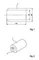
- the tubular Ausschiebekolben (3) is shown in perspective.
- the inner diameter of the Ausschiebekolbens (3) is tuned to the cross section of the inner mandrel, so that in the heated state a possible resistance-free sliding while ensuring the least possible gap is guaranteed.
- the conically tapering front (7) of the Ausschiebekolbens (3) is adapted to the shape of the inner mandrel (2) and the outer cylinder (1) in the outlet and thus ensures a minimum residual volume after the Auspressvorgang.
- Figure 7 shows the preferred possible dimensioning of the tubular Ausschiebekolbens (3) according to the dimensions of the inner mandrel (2) of Figure 5.
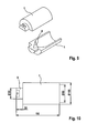
- FIG. 8 shows a perspective view of the outer cylinder (1)
- FIG. 9 shows a half-shell representation to illustrate the shape of the inner region.
- the inner outlet area (8) is tapered and adapted to the shape of the inner mandrel (2).
- the outlet flange (9) is the connection point for the melt pressure and melt temperature sensor, as well as for the micro-spray head (4) (see Fig. 3).
- a (heated) bypass not shown.
- the dimensions for the outer cylinder (1) of this embodiment are preferably shown in FIG. 10.
- the extruder for example, for cleaning, can be easily disassembled by internal mandrel (2) and Ausschiebekolben (3) can be pulled out of the Au- ⁇ enzylinder (1).
- outer cylinder (1) and inner mandrel (2) removed from the spray head (4) and the gap newly filled with granules while parallel a second pair of outer cylinder / inner mandrel (12) on the spray head ( 4) is attached and by Ausschiebekolben (3) extrudate is produced.
- the extruder according to the invention can be used in a first process stage without a spray head and with a closed outlet flange by heating and pressing granules for producing tubular and, for example, additionally colored material candles. These so-shaped, producible on stock material candles can then be further processed with the same device and downstream spray head to high-precision strand-shaped goods (principle "hot melt glue gun").
- the actual process for producing the strand-like material can be made significantly faster and more efficient by the achievable thereby very fast and easier to handle filling of the extruder with the polymeric material.
- the preferred polymer filling volume is about 225 cm 3 . While maintaining a compact overall length, the filling volume can be adjusted by increasing the cylinder and piston diameter depending on the application. For example, in the extrusion of hoses with a weight of less than or equal to 1 g / m and a material density of 1 g / cm 3 with a filling more than 200m micro-hose can be produced. With significantly smaller meter weights of the micro-tube to be produced, the possible production length per filling becomes correspondingly greater with the given usable extrusion volume. Due to the small residual volumes (eg still optimized by the chamfering of the Ausschiebekolbens to the outlet area) remain only a few percent (a few cm 3 ) material unused in the extruder.
- the small residual volumes eg still optimized by the chamfering of the Ausschiebekolbens to the outlet area
- the extruder of the invention is characterized by a compact, mechanically extremely stable construction, which does not require material-specific screw conveyance or elaborate guide elements (for example, "guide rods").
- the extruder can be adapted to the smallest extrudate dimensions and minimum amounts of melt material without any special design effort. This also ensures that the residence times are kept very short in the melt state and thus already material damage to the melt can be reduced or excluded.
- the thermal load of the polymeric Material in the extruder also be further minimized. Particularly in the case of thermally sensitive polymers with only very narrow process temperature windows, this is very advantageous for the production of thin-walled extrudates.
- the melt mass is virtually pulsation-free, in particular in connection with the detection of the pressure of the melt mass as control variable for the advance control of the discharge piston.
- fluctuations in the extrudate dimensions are essentially only limited by the molecular parameters of the material used.
- the predetermined tolerance values of the micro-hoses produced can thus be maintained within narrow limits. Scrap is thus largely avoided, the testing costs for quality assurance can be significantly reduced.
Abstract
Description
Die Erfindung betrifft Vorrichtungen zur Herstellung von strangförmigen Gütern aus polymeren Werkstoffen.The invention relates to devices for producing stranded goods made of polymeric materials.
"Strangförmige Güter" im Sinne der vorliegenden Erfindung sind beliebig lang gestreckte, wickelbare oder in gestreckter Länge als Hohl- oder Vollprofil ausgeformte Extrudate mit einer hochpräzisen Querschnittsgeometrie. Typische Produkte gemäß dieser Definition sind dünnwandig isolierte elektrische Adern, dünnwandige ein- oder mehrlumige Mikroschläuche, Vollrundschnüre, aber auch beliebig andere denkbaren miniaturisierten Profile z.B. für Dichtungszwecke im Gerätebau, für Montage und Verpackungen als Abstandhalter und vieles mehr.For the purposes of the present invention, "strand-shaped goods" are extrudates of any desired length, which can be wound or stretched in the form of a hollow or solid profile with a high-precision cross-sectional geometry. Typical products according to this definition are thin-walled insulated electrical wires, thin-walled single or multi-lumen micro hoses, full round cords, but also any other conceivable miniaturized profiles, e.g. for sealing purposes in device construction, for assembly and packaging as spacers and much more.
Insbesondere betrifft die Erfindung Vorrichtungen zur Herstellung von hochpräzisen, dünnwandigen, polymeren Mikroschläuchen und Mikroprofilen, die für einen Einsatz im medizinischen Bereich geeignet sind.In particular, the invention relates to devices for the production of high-precision, thin-walled, polymeric micro-hoses and micro-profiles, which are suitable for use in the medical field.
Zur Herstellung von strangförmigen Gütern aus Polymeren werden üblicherweise konventionelle Extruder eingesetzt. Die Figuren 1 und 2 zeigen zwei Ausführungsbeispiele bekannter Extruderbauarten mit angesetztem konventionellem Formgebungswerkzeug (11). In üblicher Ausführung besteht ein konventioneller Extruder (10) aus einer beheizbaren zylindrischen Aufnahme, in die über den Trichtereinzug Polymer-Material beispielsweise als Granulat eingefüllt wird. Durch Erwärmung wird dann das Material geschmolzen und über einen Schnecken-Vortrieb (Ein-Schnecken-Extruder) oder einen Kolben (Pasten-, Kolben- oder RAM-Extruder) über einen am Extruderauslass angeflanschten Spritzkopf (11) zur Formgebung der viskosen Polymermasse zugeführt.Conventional extruders are usually used for the production of extruded goods from polymers. Figures 1 and 2 show two embodiments of known extruder types with attached conventional forming tool (11). In the conventional design, a conventional extruder (10) consists of a heatable cylindrical receptacle into which polymer material, for example granules, is introduced via the funnel intake. By heating, the material is then melted and fed via a screw propulsion (single-screw extruder) or a piston (paste, piston or RAM extruder) via a spray head (11) flanged to the extruder outlet for shaping the viscous polymer composition.
Bei der Extrusion von strangfömigen Gütern, insbesondere dünnwandigen Polymer-Schläuchen, sind besondere Vorkehrungen zu treffen, die wiederum einen relativ kostenintensiven Rüst- und Einstellaufwand bedeuten. Bereits geringfügige Schwankungen im Materialtransport beim Formgebungsprozess, hervorgerufen beispielsweise durch Druckschwankungen infolge z.B. von Einzugsproblemen oder einer nicht optimal auf das Material ausgelegten Schnecken- und/oder Einzugsgeometrie, führen wegen der sehr kleinen Fördermengen zwangsläufig zu Abweichungen in der gewünschten Wandungsstärke und damit zu einer unerwünschten Veränderung der geometrischen und mechanischen Eigenschaften des Extrudates. Bei konventionellen Extrudern entstehen zudem aufgrund des notwendigen, meist nur sehr geringen Ausstoßvolumens auch zu lange Verweilzeiten des Polymers im Extruder-Innenbereich, was zu einer thermischen Vorschädigung des polymeren Werkstoffs führen kann.In the extrusion of extruded goods, in particular thin-walled polymer tubing, special precautions have to be taken, which in turn mean a relatively expensive set-up and adjustment effort. Even minor fluctuations in the material transport in the molding process, caused for example by pressure fluctuations due to e.g. Feeding problems or not optimally designed for the material screw and / or Einzugsgeometrie, inevitably lead to deviations in the desired wall thickness and thus to an undesirable change in the geometric and mechanical properties of the extrudate because of the very small flow rates. In conventional extruders also arise due to the necessary, usually only very low output volume too long residence times of the polymer in the extruder interior, which can lead to a thermal pre-damage of the polymeric material.
Insbesondere im Bereich der Medizintechnik sind die Qualitätsanforderungen sehr hoch, so dass bei herkömmlichen Extrudern zusätzliche Vorkehrungen getroffen werden müssen, um die engen Spezifikationen einzuhalten. Eine entsprechend aufwändige Vorrichtung zur Herstellung von dünnwandigen Polymerschläuchen für medizinische Anwendungen ist beschrieben in der
Die Erfindung geht aus von dieser Schrift als nächstliegendem Stand der Technik. Aufgabe der Erfindung ist es, eine alternative Vorrichtung zur Herstellung von beliebigen strangförmigen Gütern anzugeben, die eine hohe Präzision der Extrudate bei gleichzeitiger einfacher Handhabung des Prozesses gewährleistet.The invention is based on this document as the closest prior art. The object of the invention is to provide an alternative device for the production of any strand-shaped goods, which ensures a high precision of the extrudates with simultaneous ease of use of the process.
Diese Aufgabe wird bei einem Extruder gemäß Oberbegriff des Anspruchs 1 gelöst durch die Merkmale des charakterisierenden Teils des Anspruchs 1. Weitere Details unterschiedlicher Ausführungsformen und Vorzüge der Erfindung sind Gegenstand der Unteransprüche.This object is achieved in an extruder according to the preamble of
Zur Herstellung von strangförmigen Gütern aus thermoplastischen oder elastomeren Werkstoffen wird erfindungsgemäß ein Pastenextruder mit einem speziell ausgebildeten Innenvolumen vorgeschlagen, der durch einen zylinderförmigen Innendorn und einen äußeren Zylindermantel, vorzugsweise mit kreisförmigem Querschnitt definiert wird. Im Innenvolumen wird der polymere Werkstoff (z.B. PE, PA, TPU oder andere geeignete thermoplastischen Polymere und Elastomere) eingefüllt. Das polymere Rohmaterial kann beispielsweise als Pulver oder Granulat vorliegen. Grundsätzlich sind aber auch andere Querschnittsformen zur Ausgestaltung des Innenvolumens wie z.B. eine Ellipse oder ein reguläres oder nicht reguläres N-Eck mit N ≥ 3 denkbar.For the production of strand-like goods made of thermoplastic or elastomeric materials, a paste extruder with a specially designed internal volume is proposed according to the invention, which is defined by a cylindrical inner mandrel and an outer cylinder shell, preferably with a circular cross-section. The internal volume is filled with the polymeric material (e.g., PE, PA, TPU, or other suitable thermoplastic polymers and elastomers). The polymeric raw material may be present, for example, as a powder or granules. Basically, however, other cross-sectional shapes for the design of the inner volume such. an ellipse or a regular or non-regular N-corner with N ≥ 3 conceivable.
In einer alternativen Verwendung kann die Vorrichtung zur Herstellung von rohrförmigen (oder anders gestalteten) Material-Kerzen aus diesem Pulver oder Granulat verwendet werden. Solche Kerzen gewährleisten eine schnellere und effizientere Handhabung des polymeren Werkstoffes bei der Extrusion des strangförmigen Gutes.In an alternative use, the apparatus may be used to make tubular (or otherwise shaped) material candles from this powder or granules. Such candles ensure a faster and more efficient handling of the polymeric material in the extrusion of the strand-like material.
In einer erweiterten Ausführungsform des erfindungsgemäßen Extruders ist für den Außenzylinder ein Vakuumflansch vorgesehen, über den mittels ölfreier Pumpe nach dem Befüllen mit Polymer-Rohmasse die Luft im Füllvolumen abgepumpt werden kann.In an extended embodiment of the extruder according to the invention, a vacuum flange is provided for the outer cylinder, via which the air in the filling volume can be pumped off by means of oil-free pump after filling with polymer raw material.
Durch Beheizung wird die Polymermasse aufgeschmolzen und über eine hydraulische, elektrische oder pneumatische Antriebseinheit wird dann das Schmelzegut mittels eines Ausschiebekolbens ausgepresst. Hierbei wird der Kolbenweg über entsprechende Wegaufnehmer erfasst. Im Austragsbereich ist eine - vorzugsweise ebenfalls beheizte - Mischstrecke vorgesehen, bei der durch spezielle Formgebung eine Durchdringung des Schmelzeflusses im Sinne eines statischen Mischteils erfolgt und so eine gleichmäßige Durchmischung des Schmelzeguts erreicht wird.By heating, the polymer composition is melted and then via a hydraulic, electric or pneumatic drive unit, the melted material is squeezed out by means of a Ausschiebekolbens. In this case, the piston travel is detected by means of corresponding displacement transducers. In the discharge area a - preferably also heated - mixing section is provided, in which by special shaping a penetration of the melt flow in the sense a static mixing part takes place and so a uniform mixing of the melted material is achieved.
Im anschließenden Übergangsbereich vom Extruder zum formgebenden Teil (Spritzkopf) sind Mittel zur Erfassung von Temperatur und Druck der Schmelzemasse vorgesehen. Das erhaltene Drucksignal wird über Steuereinrichtungen in Verbindung mit dem Wegsignal zur verzögerungsfreien Regelung des Kolbenvortriebs im Sinne einer Druck-Weg-Regelung eingesetzt. Damit ist ein schwankungsfreier Materialstrom erreichbar, der über einen Schmelzekanal und beheizten Flanschverbindungen einem konventionellen Längs- oder QuerSpritzkopf, vorzugsweise mit manueller Feinzentrierung, zugeführt werden kann.In the subsequent transition region from the extruder to the forming part (spray head) means for detecting the temperature and pressure of the melt mass are provided. The pressure signal obtained is used via control devices in conjunction with the path signal for the delay-free control of the piston propulsion in the sense of a pressure-path control. This achieves a fluctuation-free material flow which can be supplied via a melt channel and heated flange connections to a conventional longitudinal or transverse spray head, preferably with manual fine centering.
Da die Materialmengen für Mikroschläuche sehr klein sind, sind die freien Volumina des Schmelzekanals und im Spritzkopf weitestgehend minimiert (MikroSpritzkopf). Damit können mögliche rheologisch bedingte Fliessanomalien, wie z.B. Kompressions- oder "Slip-Stick"-Effekte so reduziert werden, dass die Schmelze aus der Bügelzone des Schlauchwerkzeugs praktisch pulsationsfrei austreten kann und für die resultierende Geometrie des Extrudates somit nur die Strangaufweitung als Funktion des Massedrucks und der Abzuggeschwindigkeit berücksichtigt werden muss.Since the amounts of material for micro hoses are very small, the free volumes of the melt channel and in the spray head are minimized as far as possible (micro-spray head). Thus, possible rheological flow anomalies such as e.g. Compression or "slip-stick" effects are reduced so that the melt from the ironing zone of the hose tool can emerge virtually pulsation-free and thus only the strand expansion as a function of the melt pressure and the withdrawal speed must be considered for the resulting geometry of the extrudate.
Nachgeschaltet ist eine konventionelle Kühl-, Kalibrier - und Abzugseinheit inklusive Schneidvorrichtung, die in ihren Dimensionen an die kleinen Extrudat-Durchmesser angepasst sind.Downstream is a conventional cooling, calibration and extraction unit including cutting device, which are adapted in their dimensions to the small extrudate diameter.
Die Erfindung wird im Folgenden anhand eines bevorzugten Ausführungsbeispiels unter Bezugnahme auf die Figuren und den darin angegebenen Bezugszeichen näher erläutert.The invention will be explained in more detail below with reference to a preferred embodiment with reference to the figures and the reference numerals therein.
- Figur 1FIG. 1
- Konventioneller Ein-Schnecken Extruder mit einem konventionellen Spritzkopf als FormgebungswerkzeugConventional single-screw extruder with a conventional spray head as a forming tool
- Figur 2FIG. 2
- Konventioneller Kolben-Extruder mit einem konventionellen Spritzkopf als FormgebungswerkzeugConventional piston extruder with a conventional spray head as a shaping tool
- Figur 3FIG. 3
- Übersicht Aufbau eines Ausführungsbeispiels des erfindungsgemäßen ExtrudersOverview Structure of an embodiment of the extruder according to the invention
- Figur 4FIG. 4
- Perspektivansicht des zylindrischen Innendorns des ExtrudersPerspective view of the cylindrical internal mandrel of the extruder
- Figur 5FIG. 5
- Aufsicht Innendorn mit MaßangabenSupervision of internal mandrel with dimensions
- Figur 6FIG. 6
- Perspektivansicht rohrförmiger AusschiebekolbenPerspective view of tubular discharge piston
- Figur 7FIG. 7
- Schemaskizze Ausschiebekolben mit MaßangabenSchematic diagram of the push-out piston with dimensions
- Figur 8FIG. 8
- Perspektivansicht AußenzylinderPerspective view outer cylinder
- Figur 9FIG. 9
- Außenzylinder in Halbschalen-DarstellungOuter cylinder in half-shell representation
- Figur 10FIG. 10
- Aufsicht Außenzylinder mit MaßangabenOuter cylinder supervision with dimensions
- Figur 11FIG. 11
- Perspektivansicht zerlegter Extruder in koaxialer Anordnung der EinzelelementePerspective view of disassembled extruder in coaxial arrangement of the individual elements
- Figur 12FIG. 12
- Modularer Aufbau für ParallelbetriebModular design for parallel operation
Die Figuren 1 und 2 zeigen zum Vergleich bekannte Extruder (10) konventioneller Bauweise mit Schnecken- bzw. Kolbenmechanismus, angeflanschtem Formgebungsteil (11) und mit entsprechend gestalteten Heizelementen für eine mehrstufige Zonenbeheizung des Prozessvolumens.Figures 1 and 2 show for comparison known extruder (10) conventional design with screw or piston mechanism, flanged molding part (11) and with appropriately designed heating elements for a multi-stage zone heating of the process volume.
Figur 3 zeigt schematisch ein Ausführungsbeispiel des erfindungsgemäßen Extruders mit geöffnetem Außenzylinder (1), zylinderförmigem Innendorn (2), rohrförmigem Ausschiebekolben (3) und Mikro-Querspritzkopf (4). Diese Komponenten sind in ihren Bemaßungen und Füllvolumina aufeinander abgestimmt. Vorzugsweise sind die Materialien der Oberflächen von Außenzylinder (1), Innendorn (2) und Ausschiebekolben (3) für optimale mechanische Stabilität bzgl. Gleitverhalten und Abriebfestigkeit ausgewählt. Hierzu können die Oberflächen der Extruderelemente beispielsweise eine spezielle verschleiß- bzw. haftungsreduzierende Beschichtung, z.B. aus Titannitrit aufweisen.Figure 3 shows schematically an embodiment of the extruder according to the invention with open outer cylinder (1), cylindrical inner mandrel (2), tubular Ausschiebekolben (3) and micro-cross spray head (4). These components are matched in their dimensions and filling volumes. The materials of the outer cylinder (1), inner mandrel (2) and Ausschiebekolben (3) are preferably selected for optimum mechanical stability with respect to sliding behavior and abrasion resistance. For this purpose, the surfaces of the extruder elements, for example, have a special wear or adhesion-reducing coating, for example made of titanium nitrite.
Je nach gewünschtem Querschnittsprofil des Extrudates kann der Extruder zusammen mit beliebigen konventionellen Längs- oder Querspritzköpfen, vorzugsweise mit sehr kurzen und volumenreduzierten Fliesswegen (Mikrospritzkopf), und mit entsprechend ausgestalteten Formgebungswerkzeugen eingesetzt werden.Depending on the desired cross-sectional profile of the extrudate, the extruder can be used together with any conventional longitudinal or transverse spray heads, preferably with very short and volume-reduced flow paths (micro-spray head), and with appropriately designed shaping tools.
In Figur 4 ist der Innendorn (2) wiedergegeben. Im Innendorn sind mehrere Heizelemente, z.B. Hochleistungsheizpatronen, formschlüssig befestigt (nicht dargestellt). Vorzugsweise können die Heizelemente des Innendorns individuell angesteuert werden. Ebenfalls im Innenbereich des Innendorns sind Thermosensoren angebracht, die die aktuelle Temperaturverteilung erfassen. Mittels entsprechender Regelung der verteilten Heizelemente kann so eine optimal homogene Wärmeverteilung eingestellt und aufrechterhalten werden.FIG. 4 shows the inner mandrel (2). In the inner mandrel, several heating elements, e.g. Hochleistungsheizpatronen, positively secured (not shown). Preferably, the heating elements of the inner mandrel can be controlled individually. Thermosensors are also installed inside the inner mandrel to record the current temperature distribution. By means of appropriate control of the distributed heating elements, an optimally homogeneous heat distribution can thus be set and maintained.
In der bevorzugten Ausführungsform weist der Innendorn im Auslassbereich eine konische Verjüngung (5) auf, der zugehörige Außenzylinder (1) weist als Gegenstück eine entsprechend zulaufende Form (8) in diesem Bereich gemäß Figur 9 auf. In diesem konischen Bereich können zusätzliche Oberflächenstrukturen (6) eingebracht werden, die für eine gleichmäßige Durchmischung der Schmelze während des Ausströmens sorgen. Vorzugsweise sind die Oberflächenstrukturen (6) rautenförmig ausgestaltet. Figur 5 zeigt den Innendorn in Aufsicht mit typischen Maßangaben in Millimetern als mögliches Ausführungsbeispiel.In the preferred embodiment, the inner mandrel in the outlet region has a conical taper (5), the associated outer cylinder (1) has as its counterpart a corresponding tapered shape (8) in this region according to FIG. In this conical region additional surface structures (6) can be introduced, which ensure a uniform mixing of the melt during the outflow. Preferably, the surface structures (6) are designed diamond-shaped. Figure 5 shows the inner mandrel in plan view with typical dimensions in millimeters as a possible embodiment.
In Figur 6 ist der rohrförmige Ausschiebekolben (3) perspektivisch dargestellt. Der Innendurchmesser des Ausschiebekolbens (3) ist auf den Querschnitt des Innendorns abgestimmt, so dass im beheizten Zustand ein möglichst widerstandsfreies Gleiten bei gleichzeitig möglichst geringem Zwischenraum gewährleistet ist. Die konisch zulaufende Front (7) des Ausschiebekolbens (3) ist der Formgebung des Innendorns (2) und des Außenzylinders (1) im Auslassbereich angepasst und gewährleistet so ein minimales Restvolumen nach dem Auspressvorgang. Figur 7 zeigt die bevorzugte mögliche Bemaßung des rohrförmigen Ausschiebekolbens (3) entsprechend der Dimensionierung des Innendorns (2) nach Figur 5.In Figure 6, the tubular Ausschiebekolben (3) is shown in perspective. The inner diameter of the Ausschiebekolbens (3) is tuned to the cross section of the inner mandrel, so that in the heated state a possible resistance-free sliding while ensuring the least possible gap is guaranteed. The conically tapering front (7) of the Ausschiebekolbens (3) is adapted to the shape of the inner mandrel (2) and the outer cylinder (1) in the outlet and thus ensures a minimum residual volume after the Auspressvorgang. Figure 7 shows the preferred possible dimensioning of the tubular Ausschiebekolbens (3) according to the dimensions of the inner mandrel (2) of Figure 5.
Figur 8 gibt eine Perspektivansicht des Außenzylinders (1) wieder, Figur 9 zeigt eine Halbschalendarstellung zur Verdeutlichung der Formgebung des Innenbereichs. Auch hier ist der innere Auslassbereich (8) konisch zulaufend gestaltet und der Formgebung des Innendorns (2) angepasst. Der Austrittsflansch (9) ist die Anschlussstelle für den Massedruck- und Massetemperaturfühler, sowie für den Mikrospritzkopf (4) (vgl. Fig. 3). Zur besseren Handhabung beim Anfahren der Vorrichtung kann zwischen Außenzylinder und Spritzkopf noch ein (beheizter) Bypass zwischengeschaltet sein (nicht dargestellt). Die Maßangaben für den Außenzylinder (1) dieses Ausführungsbeispiels ergeben sich vorzugsweise aus Figur 10.FIG. 8 shows a perspective view of the outer cylinder (1), FIG. 9 shows a half-shell representation to illustrate the shape of the inner region. Again, the inner outlet area (8) is tapered and adapted to the shape of the inner mandrel (2). The outlet flange (9) is the connection point for the melt pressure and melt temperature sensor, as well as for the micro-spray head (4) (see Fig. 3). For better handling when starting the device can be interposed between outer cylinder and spray head still a (heated) bypass (not shown). The dimensions for the outer cylinder (1) of this embodiment are preferably shown in FIG. 10.
Durch den modularen Aufbau des Extruders aus ineinander gesetzten Einzelkomponenten, wie in Figur 11 dargestellt, ergeben sich im Betrieb verschiedene Vorteile. So kann der Extruder, beispielsweise zur Reinigung, sehr einfach zerlegt werden, indem Innendorn (2) und Ausschiebekolben (3) aus dem Au-βenzylinder (1) gezogen werden können. Auch können für einen Parallelbetrieb, wie in Figur 12 dargestellt, Außenzylinder (1) und Innendorn (2) vom Spritzkopf (4) abgenommen und der Zwischenraum neu mit Granulat befüllt werden, während parallel ein zweites Paar Außenzylinder/Innendorn (12) am Spritzkopf (4) angesetzt ist und mittels Ausschiebekolben (3) Extrudat produziert wird.Due to the modular construction of the extruder from nested individual components, as shown in Figure 11, resulting in operation various advantages. Thus, the extruder, for example, for cleaning, can be easily disassembled by internal mandrel (2) and Ausschiebekolben (3) can be pulled out of the Au-βenzylinder (1). Also, for a parallel operation, as shown in Figure 12, outer cylinder (1) and inner mandrel (2) removed from the spray head (4) and the gap newly filled with granules while parallel a second pair of outer cylinder / inner mandrel (12) on the spray head ( 4) is attached and by Ausschiebekolben (3) extrudate is produced.
In einem alternativen Betriebsmodus kann der erfindungsgemässe Extruder in einer ersten Prozessstufe ohne Spritzkopf und mit verschlossenem Austrittsflansch durch Aufheizen und Pressen von Granulat zum Herstellen von rohrförmigen und beispielsweise zusätzlich eingefärbten Material-Kerzen verwendet werden. Diese so geformten, auf Vorrat produzierbaren Material-Kerzen können dann mit der gleichen Vorrichtung und nachgeschaltetem Spritzkopf zu hochpräzisen strangförmigen Gütern weiterverarbeitet werden (Prinzip "Schmelzkleberpistole").In an alternative operating mode, the extruder according to the invention can be used in a first process stage without a spray head and with a closed outlet flange by heating and pressing granules for producing tubular and, for example, additionally colored material candles. These so-shaped, producible on stock material candles can then be further processed with the same device and downstream spray head to high-precision strand-shaped goods (principle "hot melt glue gun").
Der eigentliche Prozess zur Herstellung des strangförmigen Gutes kann durch das dadurch erreichbare sehr schnelle und einfacher zu handhabende Befüllen des Extruders mit dem polymeren Werkstoff noch deutlich schneller und effizienter gestaltet werden.The actual process for producing the strand-like material can be made significantly faster and more efficient by the achievable thereby very fast and easier to handle filling of the extruder with the polymeric material.
Mit den in den Figuren 5, 7 und 10 angegebenen Dimensionen des Ausführungsbeispiels liegt das bevorzugte Polymer-Füllvolumen bei ca. 225 cm3. Unter Beibehaltung einer kompakten Baulänge kann das Füllvolumen durch Vergrößerung des Zylinder- und Kolbendurchmessers je nach Anwendung angepasst werden. Zum Beispiel sind bei der Extrusion von Schläuchen mit einem Gewicht von kleiner/gleich 1g/m und einer Materialdichte von 1g/cm3 mit einer Füllung mehr als 200m Mikroschlauch herstellbar. Bei deutlich kleineren Metergewichten des zu fertigenden Mikroschlauches wird mit dem gegebenen nutzbaren Auspressvolumen die mögliche Fertigungslänge pro Füllung entsprechend noch größer. Durch die geringen Restvolumina (z.B. noch optimiert durch das Anschrägen des Ausschiebekolbens zum Austrittbereich) verbleiben nur wenige Prozent (einige cm3) Material ungenutzt im Extruder.With the dimensions of the embodiment given in FIGS. 5, 7 and 10, the preferred polymer filling volume is about 225 cm 3 . While maintaining a compact overall length, the filling volume can be adjusted by increasing the cylinder and piston diameter depending on the application. For example, in the extrusion of hoses with a weight of less than or equal to 1 g / m and a material density of 1 g / cm 3 with a filling more than 200m micro-hose can be produced. With significantly smaller meter weights of the micro-tube to be produced, the possible production length per filling becomes correspondingly greater with the given usable extrusion volume. Due to the small residual volumes (eg still optimized by the chamfering of the Ausschiebekolbens to the outlet area) remain only a few percent (a few cm 3 ) material unused in the extruder.
Gegenüber den in Figur 1 und 2 dargestellten konventionellen Vorrichtungen zeichnet sich der erfindungsgemäße Extruder durch eine kompakte, mechanisch äußerst stabile Bauweise aus, die ohne materialspezifische Schneckenförderung oder aufwändige Führungselemente (z.B. "guide rods") auskommt. Allein durch entsprechende Dimensionierung der Einzelkomponenten kann der Extruder ohne besonderen Konstruktionsaufwand auf kleinste Extrudatdimensionen und minimale Schmelzegutmengen angepasst werden. Damit ist auch erreicht, dass die Verweilzeiten im Schmelzezustand sehr kurz gehalten werden und bereits dadurch Materialschädigungen des Schmelzguts reduziert bzw. ausgeschlossen werden können.Compared with the conventional devices shown in Figures 1 and 2, the extruder of the invention is characterized by a compact, mechanically extremely stable construction, which does not require material-specific screw conveyance or elaborate guide elements (for example, "guide rods"). Just by appropriate dimensioning of the individual components, the extruder can be adapted to the smallest extrudate dimensions and minimum amounts of melt material without any special design effort. This also ensures that the residence times are kept very short in the melt state and thus already material damage to the melt can be reduced or excluded.
Durch räumlich im Extruder verteilt angeordnete Heizelemente und Thermosensoren, die individuell über die komplette Verfahrenslänge graduell angesteuert und auf das optimale Temperaturprofil des jeweiligen Schmelzegutes angepasst werden können, kann die thermische Belastung des polymeren Werkstoffes im Extruder zudem weiter minimiert werden. Insbesondere bei thermisch sensitiven Polymeren mit nur sehr schmalen Prozesstemperaturfenstern ist dies für die Herstellung von dünnwandigen Extrudaten sehr vorteilhaft.By spatially distributed in the extruder arranged heating elements and thermosensors, which can be controlled individually over the entire process length gradually and adapted to the optimum temperature profile of the respective melt, the thermal load of the polymeric Material in the extruder also be further minimized. Particularly in the case of thermally sensitive polymers with only very narrow process temperature windows, this is very advantageous for the production of thin-walled extrudates.
Durch die Optimierung des polymeren Fliessverhaltens in Funktion von Druck, Temperatur und Prozessvolumen mittels zuvor beschriebener Maßnahmen ergibt sich - insbesondere in Verbindung mit der Erfassung des Drucks der Schmelzemasse als Stellgröße zur Vortriebsregelung des Ausschiebekolbens - ein nahezu pulsationsfreies Austreten der Schmelzemasse. Damit sind Schwankungen in den Extrudatabmessungen im Wesentlichen nur bedingt durch die molekularen Parameter des eingesetzten Werkstoffs. Die vorgegebenen Toleranzwerte der erzeugten Mikroschläuche können somit in engen Grenzen eingehalten werden. Ausschuss wird damit weitgehend vermieden, der Prüfaufwand zur Qualitätssicherung kann deutlich reduziert werden.By optimizing the polymer flow behavior as a function of pressure, temperature and process volume by means of measures described above, the melt mass is virtually pulsation-free, in particular in connection with the detection of the pressure of the melt mass as control variable for the advance control of the discharge piston. Thus, fluctuations in the extrudate dimensions are essentially only limited by the molecular parameters of the material used. The predetermined tolerance values of the micro-hoses produced can thus be maintained within narrow limits. Scrap is thus largely avoided, the testing costs for quality assurance can be significantly reduced.
Da die verschiedenen Steuerungsvorgänge (Regelung des Auspressvorgangs usw.) weitgehend automatisiert werden können, ergeben sich auch bei Einsatz verschiedener Materialen sehr kurze Rüst- und Einfahrzeiten. Aufgrund der einfachen Bedienung des Extrusionsprozesses und den im Vergleich äußerst kompakten Abmessungen des Extruders, sind im Betrieb gegenüber einer konventionellen Extrusionslinie weniger Personal- und Zeitaufwand und nur ein geringer Platzbedarf einzusetzen. Der Extruder kann praktisch in jeder beliebigen räumlichen Lage eingesetzt werden. Insgesamt fallen bei Einsatz des erfindungsgemäßen Extruders deutlich geringere Personal-, Unterhalts- und Investitionskosten an.Since the various control processes (regulation of the Auspressvorgangs, etc.) can be largely automated, resulting in very short setup and retraction times even when using different materials. Due to the simple operation of the extrusion process and the extremely compact dimensions of the extruder in comparison to a conventional extrusion line, less work and time and only a small amount of space is required. The extruder can be used in virtually any spatial position. Overall, when using the extruder according to the invention significantly lower staff, maintenance and investment costs.
Claims (10)
dadurch gekennzeichnet,
dass das Innenvolumen als Zwischenraum zwischen einem Außenzylinder (1) und einem zylinderförmigen Innendorn (2) gebildet wird, wobei Außenzylinder (1) und Innenzylinder (2) koaxial zueinander angeordnet sind und als Mittel zum Auspressen des Schmelzeguts ein rohrförmiger Ausschiebekolben (3) vorgesehen ist, der in seinen Abmessungen dem Innenvolumen dichtend angepasst ist.Apparatus for extruding strand-like goods of thermoplastic or elastomeric materials, having an internal volume for filling with polymer raw material, heating elements for melting the polymer raw material in the internal volume, means for extruding the melted product thus obtained in an outlet region via an outlet channel with a spray head (4) is connected,
characterized,
in that the inner volume is formed as a gap between an outer cylinder (1) and a cylindrical inner mandrel (2), the outer cylinder (1) and inner cylinder (2) being arranged coaxially with one another and a tubular discharge piston (3) being provided as means for extruding the melt , which is dimensionally adapted to the internal volume in its dimensions.
dadurch gekennzeichnet,
dass das Innenvolumen im Auslassbereich zum Austrittskanal hin konisch zusammenläuft, indem in diesem Bereich die Innenseite des Außenzylinders (1) eine konische Form (8) aufweist und der zylinderförmige Innendorn (2) in diesem Bereich (5) entsprechend kegelförmig ausgebildet ist.Device according to claim 1,
characterized,
is that the internal volume in the outlet to the outlet channel converges conically, by the inside of the outer cylinder (1) has in this area a conical shape (8) and the cylindrical inner mandrel (2) in this region (5) formed correspondingly conical.
dadurch gekennzeichnet,
dass im konisch zusammenlaufenden Bereich des Innenvolumens auf der Innenwandung (8) des Außenzylinders (1) oder dem kegelförmig zulaufenden Bereich (5) des Innendorns (2) Oberflächenstrukturen (6) - z.B. rautenförmige Erhebungen - vorhanden sind, die eine Durchmischung des Schmelzeguts während des Auspressvorgangs bewirken.Device according to claim 2,
characterized,
that, in the conically converging portion of the inner volume on the inner wall (8) of the outer cylinder (1) or the tapered portion (5) of the inner mandrel (2) surface structures (6) - for example, diamond-shaped projections - are present, the thorough mixing of the Schmelzeguts during Effect extrusion process.
dadurch gekennzeichnet,
dass der rohrförmige Ausschiebekolben (3) zum Auslassbereich eine konische Verjüngung (7) aufweist.Apparatus according to claim 1, 2 or 3,
characterized,
in that the tubular discharge piston (3) has a conical taper (7) to the outlet region.
dadurch gekennzeichnet,
dass insbesondere am Austrittsflansch des Extruders mindestens ein Sensor zur Messung des Drucks des Schmelzeguts vorhanden ist.Device according to one of the preceding claims,
characterized,
in particular that at least one sensor for measuring the pressure of the melted product is present at the outlet flange of the extruder.
dadurch gekennzeichnet,
dass Mittel zur Erfassung der Position des Ausschiebekolbens (3) vorhanden sind, sowie Mittel zur Regelung des Kolbenvortriebs in Abhängigkeit vom gemessenen Druck im Schmelzegut.Device according to claim 5,
characterized,
in that means for detecting the position of the push-out piston (3) are present, as well as means for controlling the piston advance as a function of the measured pressure in the melt.
dadurch gekennzeichnet,
dass Mittel vorhanden sind zum Abpumpen vorhandener Luft im Innenvolumen nach Befüllung mit Polymer-Rohmaterial.Device according to one of the preceding claims,
characterized,
that means are present for pumping out existing air in the inner volume after filling with polymer raw material.
dadurch gekennzeichnet,
dass zum Aufschmelzen des Polymer-Rohmaterials Heizelemente, z.B. Heizpatronen, räumlich verteilt im Innendorn (3) eingesetzt sind und/oder Heizelemente, z.B. Heizbänder (10), nebeneinander auf der Außenmantelfläche des Außenzylinders (1) angeordnet sind.Device according to one of the preceding claims,
characterized,
in that heating elements, eg heating cartridges, are spatially distributed in the inner mandrel (3) and / or heating elements, eg heating tapes (10), are arranged side by side on the outer circumferential surface of the outer cylinder (1) for melting the polymer raw material.
dadurch gekennzeichnet,
dass die Heizelemente individuell oder in mehreren Gruppen mittels entsprechend angebrachter Thermosensoren und nachgeschalteten Regeleinheiten regelbar sind.Device according to claim 5,
characterized,
that the heating elements can be controlled individually or in several groups by means of correspondingly mounted thermal sensors and downstream control units.
Applications Claiming Priority (1)
| Application Number | Priority Date | Filing Date | Title |
|---|---|---|---|
| DE102006035960A DE102006035960A1 (en) | 2006-08-02 | 2006-08-02 | Device for producing stranded goods |
Publications (2)
| Publication Number | Publication Date |
|---|---|
| EP1884341A2 true EP1884341A2 (en) | 2008-02-06 |
| EP1884341A3 EP1884341A3 (en) | 2011-11-16 |
Family
ID=38683488
Family Applications (1)
| Application Number | Title | Priority Date | Filing Date |
|---|---|---|---|
| EP07013446A Withdrawn EP1884341A3 (en) | 2006-08-02 | 2007-07-10 | Method for manufacturing strand shaped articles |
Country Status (3)
| Country | Link |
|---|---|
| US (1) | US20080029937A1 (en) |
| EP (1) | EP1884341A3 (en) |
| DE (1) | DE102006035960A1 (en) |
Families Citing this family (5)
| Publication number | Priority date | Publication date | Assignee | Title |
|---|---|---|---|---|
| US9815223B2 (en) * | 2008-05-16 | 2017-11-14 | Gala Industries, Inc. | Method and device for extrusion of hollow pellets |
| US20100207291A1 (en) * | 2009-02-13 | 2010-08-19 | Boston Scientific Scimed, Inc. | Method of Making a Tubular Member |
| US9174853B2 (en) * | 2013-12-06 | 2015-11-03 | Gelest Technologies, Inc. | Method for producing high purity germane by a continuous or semi-continuous process |
| CN104228114B (en) * | 2014-10-09 | 2016-01-13 | 西安近代化学研究所 | A kind of continuously extruding and molding device |
| CN115891096B (en) * | 2022-11-04 | 2023-10-03 | 江苏威腾体育产业股份有限公司 | Extrusion molding equipment for filling-free lawn fiber coiled material |
Citations (2)
| Publication number | Priority date | Publication date | Assignee | Title |
|---|---|---|---|---|
| JP3079560B2 (en) * | 1990-11-07 | 2000-08-21 | 松下電器産業株式会社 | Pre-plastic injection molding machine and control method thereof |
| EP2036696A1 (en) * | 2006-06-28 | 2009-03-18 | Toyo Tire & Rubber Co. Ltd. | Process for producing tire through volume extrusion |
Family Cites Families (24)
| Publication number | Priority date | Publication date | Assignee | Title |
|---|---|---|---|---|
| BE560504A (en) * | 1956-09-05 | 1900-01-01 | ||
| US2945265A (en) * | 1957-02-25 | 1960-07-19 | Revere Corp America | Method for making insulated wire |
| US3008187A (en) * | 1959-01-05 | 1961-11-14 | Raybestos Manhattan Inc | Method and apparatus for extruding polytetrafluoroethylene tubing |
| GB975633A (en) * | 1961-10-09 | 1964-11-18 | Raybestos Manhattan Inc | Method and apparatus for making polytetrafluoroethylene tubing |
| US3212136A (en) * | 1962-12-17 | 1965-10-19 | Phillips Petroleum Co | Die for extruding hollow articles |
| US3354501A (en) * | 1963-12-31 | 1967-11-28 | Columbia Broadcasting Syst Inc | Plasticizing apparatus with automatic temperature controlling means |
| DE2028064A1 (en) * | 1970-06-08 | 1971-12-16 | Troester Maschf Paul | Screw press for molding preplasticized elastomers or thermoplastics |
| DE2059496C3 (en) * | 1970-12-03 | 1973-07-12 | Maschf Augsburg Nuernberg Ag | Device for plasticizing plastics |
| US3950118A (en) * | 1974-05-17 | 1976-04-13 | Phillips Petroleum Company | Control of temperature profile across a heat exchanger |
| GB1573196A (en) * | 1975-12-15 | 1980-08-20 | Sumito Electric Ind Ltd | Method and apparatus for extruding polytetrafluoroethlene tubing |
| DE2725804C2 (en) * | 1977-06-08 | 1986-07-31 | Werner & Pfleiderer, 7000 Stuttgart | Method for building up pressure in a press for an explosive mass and switching arrangement for carrying out the method |
| DE2836052C2 (en) * | 1978-08-17 | 1984-08-30 | Ruhrchemie Ag, 4200 Oberhausen | Ram extruder for the production of plastic pipes |
| JPS55107431A (en) * | 1979-02-13 | 1980-08-18 | Japan Steel Works Ltd:The | Accumulator head for molding cylinder by thermoplastic resin |
| JPS5715943A (en) * | 1980-07-02 | 1982-01-27 | Matsushita Electric Ind Co Ltd | Vacuum extruder |
| JPS58212919A (en) * | 1982-06-07 | 1983-12-10 | Idemitsu Petrochem Co Ltd | Die for multilayer extrusion molding |
| US4721589A (en) * | 1983-09-22 | 1988-01-26 | Harrel, Inc. | Extruder viscosity control system and method |
| US4743480A (en) * | 1986-11-13 | 1988-05-10 | W. L. Gore & Associates, Inc. | Apparatus and method for extruding and expanding polytetrafluoroethylene tubing and the products produced thereby |
| US5204045A (en) * | 1990-06-15 | 1993-04-20 | Symplastics Limited | Process for extruding polymer shapes with smooth, unbroken surface |
| US5198239A (en) * | 1991-07-08 | 1993-03-30 | Beavers Charles T | Apparatus for co-extruding two food products |
| FR2680338B1 (en) * | 1991-08-16 | 1993-10-01 | Henryk Prus | SHEAR PLASTIFICATION DEVICE FOR INJECTION UNITS FOR PLASTIC MOLDING MACHINES. |
| EP0799684A1 (en) * | 1996-04-03 | 1997-10-08 | Zw Hydraulik Ag | Preformer with two or several extrusion cylinders revolving around an axis |
| DE19700723C2 (en) * | 1997-01-11 | 2002-02-14 | Keicher Engineering Gmbh | extruder |
| US6814561B2 (en) * | 2001-10-30 | 2004-11-09 | Scimed Life Systems, Inc. | Apparatus and method for extrusion of thin-walled tubes |
| US20060103048A1 (en) * | 2004-11-17 | 2006-05-18 | Crumm Aaron T | Extrusion die for making a part with controlled geometry |
-
2006
- 2006-08-02 DE DE102006035960A patent/DE102006035960A1/en not_active Withdrawn
-
2007
- 2007-07-10 EP EP07013446A patent/EP1884341A3/en not_active Withdrawn
- 2007-07-12 US US11/776,921 patent/US20080029937A1/en not_active Abandoned
Patent Citations (2)
| Publication number | Priority date | Publication date | Assignee | Title |
|---|---|---|---|---|
| JP3079560B2 (en) * | 1990-11-07 | 2000-08-21 | 松下電器産業株式会社 | Pre-plastic injection molding machine and control method thereof |
| EP2036696A1 (en) * | 2006-06-28 | 2009-03-18 | Toyo Tire & Rubber Co. Ltd. | Process for producing tire through volume extrusion |
Also Published As
| Publication number | Publication date |
|---|---|
| EP1884341A3 (en) | 2011-11-16 |
| US20080029937A1 (en) | 2008-02-07 |
| DE102006035960A1 (en) | 2008-02-07 |
Similar Documents
| Publication | Publication Date | Title |
|---|---|---|
| EP1884341A2 (en) | Method for manufacturing strand shaped articles | |
| DE102013002559B4 (en) | Single-screw extruder and process for plasticizing plastic polymers | |
| WO2010084094A2 (en) | Extrusion system comprising a back pressure controlling brake device | |
| DE2522357A1 (en) | BLOWDER EXTRUDERS | |
| DE202007016630U1 (en) | Apparatus for the continuous production of a composite pipe with pipe socket | |
| EP2148773A1 (en) | Device for the extrusion of web-shaped or belt-shaped preforms from thermoplastic plastic, and method for the extrusion of such a preform | |
| EP3697594B1 (en) | Print head for a 3d printer | |
| CH623506A5 (en) | Extrusion tool for producing pipes from plastic | |
| DE4307568C2 (en) | Method and device for heating and extruding a preform | |
| DE2059496A1 (en) | Temp-controlled plasticiser - with supplementary dielectric heating | |
| DE1145787B (en) | Screw extruder with a damming section, the cross section of which is variable | |
| WO2019109114A1 (en) | Printhead for the layer-by-layer application of material | |
| EP2626188B1 (en) | Adjustable calibration method | |
| CH642906A5 (en) | METHOD AND DEVICE FOR PRODUCING MOLDED BODIES FROM HIGH-MOLECULAR LOW-PRESSURE POLYAETHYLENE, AND A RAMEXTRUDER FOR IMPLEMENTING THE METHOD. | |
| EP0663277B1 (en) | Apparatus for extrusion-welding thermoplastic materials | |
| EP0153687A2 (en) | Apparatus for making propellant powder in a rod-like shape | |
| EP0407847A1 (en) | Method and apparatus for manufacturing hollow thermoplastic bodies | |
| EP2153970B1 (en) | Method for operating an extrusion line for plastic hollow profiles | |
| EP3153296B1 (en) | Extrusion head for a device for producing a composite pipe | |
| EP2436501B1 (en) | Method and device for manufacturing an extruded plastic product | |
| AT524541B1 (en) | Device for degassing and method for degassing a plasticized mass | |
| EP3554797A1 (en) | Printhead for the layer-by-layer application of material | |
| AT522497B1 (en) | Method for producing a pipe and device for carrying out the method | |
| EP3220126A1 (en) | Device for determining the viscosity of liquids | |
| DE102020114448A1 (en) | METHOD AND APPARATUS FOR MANUFACTURING AN EXTRUDED PRODUCT |
Legal Events
| Date | Code | Title | Description |
|---|---|---|---|
| PUAI | Public reference made under article 153(3) epc to a published international application that has entered the european phase |
Free format text: ORIGINAL CODE: 0009012 |
|
| AK | Designated contracting states |
Kind code of ref document: A2 Designated state(s): AT BE BG CH CY CZ DE DK EE ES FI FR GB GR HU IE IS IT LI LT LU LV MC MT NL PL PT RO SE SI SK TR |
|
| AX | Request for extension of the european patent |
Extension state: AL BA HR MK YU |
|
| PUAL | Search report despatched |
Free format text: ORIGINAL CODE: 0009013 |
|
| AK | Designated contracting states |
Kind code of ref document: A3 Designated state(s): AT BE BG CH CY CZ DE DK EE ES FI FR GB GR HU IE IS IT LI LT LU LV MC MT NL PL PT RO SE SI SK TR |
|
| AX | Request for extension of the european patent |
Extension state: AL BA HR MK RS |
|
| RIC1 | Information provided on ipc code assigned before grant |
Ipc: B29C 47/36 20060101ALI20111010BHEP Ipc: B29C 47/54 20060101AFI20111010BHEP |
|
| 17P | Request for examination filed |
Effective date: 20120514 |
|
| AKX | Designation fees paid |
Designated state(s): CH DE GB IE LI NL |
|
| 17Q | First examination report despatched |
Effective date: 20120921 |
|
| STAA | Information on the status of an ep patent application or granted ep patent |
Free format text: STATUS: THE APPLICATION IS DEEMED TO BE WITHDRAWN |
|
| 18D | Application deemed to be withdrawn |
Effective date: 20130625 |