EP1882229B1 - Electronic cards and methods for making same - Google Patents
Electronic cards and methods for making same Download PDFInfo
- Publication number
- EP1882229B1 EP1882229B1 EP06752097.3A EP06752097A EP1882229B1 EP 1882229 B1 EP1882229 B1 EP 1882229B1 EP 06752097 A EP06752097 A EP 06752097A EP 1882229 B1 EP1882229 B1 EP 1882229B1
- Authority
- EP
- European Patent Office
- Prior art keywords
- electronic card
- card
- processor
- general processor
- circuit board
- Prior art date
- Legal status (The legal status is an assumption and is not a legal conclusion. Google has not performed a legal analysis and makes no representation as to the accuracy of the status listed.)
- Not-in-force
Links
Images


Classifications
-
- G—PHYSICS
- G06—COMPUTING; CALCULATING OR COUNTING
- G06K—GRAPHICAL DATA READING; PRESENTATION OF DATA; RECORD CARRIERS; HANDLING RECORD CARRIERS
- G06K19/00—Record carriers for use with machines and with at least a part designed to carry digital markings
- G06K19/06—Record carriers for use with machines and with at least a part designed to carry digital markings characterised by the kind of the digital marking, e.g. shape, nature, code
- G06K19/067—Record carriers with conductive marks, printed circuits or semiconductor circuit elements, e.g. credit or identity cards also with resonating or responding marks without active components
- G06K19/07—Record carriers with conductive marks, printed circuits or semiconductor circuit elements, e.g. credit or identity cards also with resonating or responding marks without active components with integrated circuit chips
- G06K19/077—Constructional details, e.g. mounting of circuits in the carrier
-
- B—PERFORMING OPERATIONS; TRANSPORTING
- B42—BOOKBINDING; ALBUMS; FILES; SPECIAL PRINTED MATTER
- B42D—BOOKS; BOOK COVERS; LOOSE LEAVES; PRINTED MATTER CHARACTERISED BY IDENTIFICATION OR SECURITY FEATURES; PRINTED MATTER OF SPECIAL FORMAT OR STYLE NOT OTHERWISE PROVIDED FOR; DEVICES FOR USE THEREWITH AND NOT OTHERWISE PROVIDED FOR; MOVABLE-STRIP WRITING OR READING APPARATUS
- B42D25/00—Information-bearing cards or sheet-like structures characterised by identification or security features; Manufacture thereof
- B42D25/20—Information-bearing cards or sheet-like structures characterised by identification or security features; Manufacture thereof characterised by a particular use or purpose
- B42D25/21—Information-bearing cards or sheet-like structures characterised by identification or security features; Manufacture thereof characterised by a particular use or purpose for multiple purposes
-
- G—PHYSICS
- G06—COMPUTING; CALCULATING OR COUNTING
- G06K—GRAPHICAL DATA READING; PRESENTATION OF DATA; RECORD CARRIERS; HANDLING RECORD CARRIERS
- G06K19/00—Record carriers for use with machines and with at least a part designed to carry digital markings
- G06K19/06—Record carriers for use with machines and with at least a part designed to carry digital markings characterised by the kind of the digital marking, e.g. shape, nature, code
- G06K19/067—Record carriers with conductive marks, printed circuits or semiconductor circuit elements, e.g. credit or identity cards also with resonating or responding marks without active components
- G06K19/07—Record carriers with conductive marks, printed circuits or semiconductor circuit elements, e.g. credit or identity cards also with resonating or responding marks without active components with integrated circuit chips
- G06K19/0701—Record carriers with conductive marks, printed circuits or semiconductor circuit elements, e.g. credit or identity cards also with resonating or responding marks without active components with integrated circuit chips at least one of the integrated circuit chips comprising an arrangement for power management
- G06K19/0702—Record carriers with conductive marks, printed circuits or semiconductor circuit elements, e.g. credit or identity cards also with resonating or responding marks without active components with integrated circuit chips at least one of the integrated circuit chips comprising an arrangement for power management the arrangement including a battery
-
- G—PHYSICS
- G06—COMPUTING; CALCULATING OR COUNTING
- G06K—GRAPHICAL DATA READING; PRESENTATION OF DATA; RECORD CARRIERS; HANDLING RECORD CARRIERS
- G06K19/00—Record carriers for use with machines and with at least a part designed to carry digital markings
- G06K19/06—Record carriers for use with machines and with at least a part designed to carry digital markings characterised by the kind of the digital marking, e.g. shape, nature, code
- G06K19/067—Record carriers with conductive marks, printed circuits or semiconductor circuit elements, e.g. credit or identity cards also with resonating or responding marks without active components
- G06K19/07—Record carriers with conductive marks, printed circuits or semiconductor circuit elements, e.g. credit or identity cards also with resonating or responding marks without active components with integrated circuit chips
- G06K19/077—Constructional details, e.g. mounting of circuits in the carrier
- G06K19/0772—Physical layout of the record carrier
- G06K19/07722—Physical layout of the record carrier the record carrier being multilayered, e.g. laminated sheets
Description
- This invention relates generally to electronic cards and more particularly to secure electronic transactions cards such as Smart Cards.
US 6 705 520 B1 discloses such a card. - There are a great many applications for electronic security. For example, security is desirable or required for financial transactions, or for providing access to various physical and non-physical resources. One area of great concern for electronic security is in the field of financial transaction cards, e.g. credit and debit cards.
- Conventional credit cards, debit cards and other financial transaction cards (hereafter "transaction cards") have a typically plastic body upon which is embossed a 16 digit account number and other data. A magnetic strip, usually referred to as a "stripe", is adhered to the back of the card. The stripe typically magnetically encodes the account number and/or other data.
- A stripe is typically a magnetic tape material much like the magnetic tape used in digital data recording. The stripe material typically includes a magnetic oxide and binder compounds that provide the magnetic stripe with data encoding capabilities and physical durability characteristics needed for transaction card applications. While these magnetic tape components have been optimized for transaction card applications the magnetic tape used for the magnetic stripe on a transaction card is very similar to standard digital data recording tape.
- The two most common magnetic oxides used in magnetic stripe cards are referred to as low coercivity (LoCo) and high coercivity (HiCo) magnetic oxides. Coercivity measures how difficult it is to magnetize or demagnetize the stripe and is measured in oersteds. Low coercivity magnetic stripes are typically 300 oersteds and high coercivity magnetic stripes are above 2700 oersteds. A high coercivity magnetic stripe requires about three times more energy to encode or erase then does a low coercivity magnetic stripe. Many transaction card applications have gone to HiCo magnetic stripes because it is much harder to accidentally erase the encoded data than on LoCo magnetic stripes. This provides greater durability and readability of the encoded data in use for many applications.
- The encoding of the magnetic stripe on a transaction card typically follows standard digital recording techniques but is again optimized for transaction card applications. The encoded data takes the form of zones of magnetization in the magnetic stripe with alternate magnetic polarities. The north and south poles of the magnetized zones alternate in direction providing an encoding technique that can represent the binary "zeroes" and "ones" of a binary digital code.
- The standard encoding technique for the magnetic stripe on a transaction card is the F2F (Aiken double frequency) code where a binary zero is represented by a long magnetized zone and a binary one is represented by two magnetized zones, each one half the length of the zero - a long magnetized zone. The exact length of these zones of magnetization is determined by how much data needs to be recorded on the magnetic stripe. For example Track 2 data is encoded at 75 bits per inch or 75 long zero zones per inch - International Standards Organization (ISO) specifications 7811-2/6. That equates to 0.01333 inches in length for the zero magnetized zone. The binary one would then be two zones of one half that length or 0.00666 inches in length. Other lengths can be obtained for different data densities such as the 210 bits per inch used in
Track 1 andTrack 2 of the magnetic stripe. - Reading the encoded data in the magnetic stripe is accomplished by capturing the magnetic flux field extending from the magnetized zones in the stripe by a magnetic read head. The read head converts the changing magnetic flux in the coil of the read head to a voltage pattern mirroring the magnetization zones of the encoded data. The voltage pattern can then be translated by the decoding electronics into the binary zeroes and ones of the data as is well known in the industry.
- A magnetic stripe encoder consists of a magnetic write head and an electronic current drive circuit capable of magnetizing the magnetic oxide in the stripe to full magnetization (saturation). The encoding current in the write head is capable of alternating direction thereby producing alternating zones of magnetization direction in the stripe that will form the data encoding of the magnetic stripe. Transaction cards typically have their stripes encoded with account an/or other information in commercial magnetic stripe encoders prior to delivery to the consumer.
- The process of magnetic tape application to transaction cards, the encoding of the magnetic stripe and the reading of the encoded data in the magnetic stripe at point of use has been a reliable and cost effective method for portable personal data storage for financial, ID and other transaction card based applications. However, the relative ease of reading and encoding or re-encoding of the magnetic stripe data has made the magnetic stripe transaction card subject to counterfeiting, copying the data to one or more cards (often referred to as "skimming") and other fraud abuses. Skimming fraud alone is growing around the world and has reached financial dollar losses that call for immediate solutions.
- There are many security problems with conventional transaction cards. For one, the stripe is static and is not encrypted, allowing transaction card thieves to "steal", in the virtual sense, the data from the stripe and use it for unauthorized transactions. This is because with conventional magnetic stripe cards the transaction data is "exposed", i.e. not encrypted. If "picked off", the data can be used indistinguishably in a counterfeit transaction card. As such, a counterfeit transaction card can be freely used by a thief until it is cancelled.
- The skimming and counterfeiting problem has been partially addressed by MagTek Incorporated with its MagnePrint technology. MagnePrint® is a card security technology that can detect "skimmed" or magnetically altered counterfeit cards. Just as fingerprints can uniquely identify human beings, MagnePrint® can uniquely identify magstripe cards. MagnePrint® technology was discovered at Washington University in St. Louis, MO, USA. MagTek refined the technology, to bring it to practical use, and has an exclusive license to market this technology. However, MagnePrint technology requires modified card readers for its implementation, which would render obsolete millions of legacy card readers.
- In addition to a lack of security, conventional transaction cards are also quite limited in storage capacity. That is, conventional cards are limited to their stripe for storage. As such, conventional cards are not electronic cards, e.g. cards with embedded electronics such as an on-board processor and/or digital memory, and are very limited in their functionality.
- An example of an electronic card is the so-called "Smart Card", which includes both an on-board processor and digital memory. By providing an on-board electronics, a Smart Card can implement security protocols such as encryption, store large amounts of user information, etc.
- A common standard for Smart Cards is referred to as the ISO 7816 standard. With this protocol, a Smart Card is provided with an electrical interface including a number of electrically conductive and externally accessible contact pads which are coupled to an embedded secure processor. The Smart Card is inserted into a Smart Card reader which makes electrical contact with the contact pads to provide power to and communications with the secure processor. Smart Cards, however, are not provided with embedded power, e.g. a battery. Smart cards can also include a conventional stripe which, in the prior art, does not in any way interact with the secure processor.
- Smart cards using memory chips and microprocessor chips were first introduced to provide increased data storage and to guard against some of the types of fraud found in magnetic stripe transaction cards. The Smart Cards do reduce some types of fraud but the cards are much more expensive than a magnetic stripe transaction card and the magnetic stripe readers at the point-of-transaction had to be replaced with readers that could read the data storage chip and the magnetic stripe. These cost factors and inertia in changing the existing infrastructure built up around the magnetic stripe transaction card systems and applications (e.g. "legacy" card readers) have prevented the rapid and more general acceptance of Smart Cards in the United States.
- Another factor in the slow acceptance of Smart Cards in the United States, has been the lack of visible benefits to the end user or consumer. The consumer is just as content to use the magnetic stripe as to use the chip to complete a transaction.
- While broadly adopted abroad, Smart Cards have not been extensively adopted in the U.S., as noted above. As noted above, a major reason for this is the investment made by millions of merchants in legacy card readers, which cannot communicate with the secure processors of Smart Cards. Also, Smart Cards conforming to the
ISO 7816 standard suffer from their own limitations, including severely restricted I/O, an inability to provide "smart" transactions with legacy card readers, etc. - Another limitation of smart cards in general is that they lack the ability to interact with a user when they are not in contact with a smart card reader. This limitation is due to the fact that the smart card of the prior art does not have an on-board power supply. Thus the electronic components lie dormant and do not allow for interaction. This limitation prevents a myriad of features, such as account selection, or a security feature to lock the card, etc.
- Another suggested approach, not yet in use, uses a general processor and a stripe emulator which work with legacy card readers. As used here, the term "stripe emulator" will refer to a transaction card where data transmitted to a legacy card reader is under the control of the general processor. This approach will be referred to herein as an "emulator card", which is one form of an electronic card.
- Emulator cards potentially have a number of distinct advantages over conventional credit cards. For one, a single card can emulate a number of different transaction cards, greatly reducing the bulk in one's wallet. For example, an emulator card can emulate a Visa card, a MasterCard, and an ATM card. Also, since the emulator card includes a processor, it is possible to implement additional functionality, such as security functions.
- However, emulator cards, too, have their limitations. For one, since general processors are used the security level of the card is reduced. For example, a hacker could potentially obtain data stored in unsecured electronic memory. Also, emulator cards do not address Smart Card protocols, as they are designed to work with legacy card readers. For example, as with conventional credit cards, data flows from the emulator card to the legacy card reader, and not vice versa. Still further, the information that can be provided by the emulator card is limited to the amount of information that a conventional stripe can hold and that a legacy card reader can read.
- The need for fraud reduction with a versatile and inexpensively manufactured electronic card is urgent. In the U.S., fraud is tending to cover from 7.5 to 12 basis points in credit card transactions, and skimming alone is estimated to cost $8 billion dollars in 2005. Internationally, the need is even more dire, with fraud tending from 25 to 40 basis points, with 60 percent of that being due to skimming. Nevertheless, merchants in the United States and elsewhere are reluctant to invest the resources necessary to change all of their current magnetic-card transaction equipment for various reasons, including cost, inconvenience, disruption and lack of reliability.
- There are other uses for electronic cards other than for financial transactions. For example, electronic cards have been used for security purposes to allow, for example, personnel to high security areas of a building ("access control"). Electronic cards can therefore be used for a variety of purposes where the identity and/or status of the bearer needs to be verified by a physical card or "token."
- Electronic cards, as noted above, tend to be relatively expensive compared to conventional, non-electronic, magnetic stripe cards. This is due, in part, to the cost of the electronic components and it due, in part, to the complexity of manufacture of electronic cards. For example, care must be taken during lamination of electronic cards that the heat and/or pressure do not damage the sensitive electronic components. Also, electronic cards should remain thin, flexible and preferably of the same dimensions as conventional cards. As another example, stripe emulators tend to be difficult to design and manufacture such that they work with legacy readers.
- Furthermore, powering the electronic circuitry of electronic cards tends to be problematical. For example, Smart Cards are powered by their readers, limiting their usefulness in non-contact applications. A good solution for powering ubiquitous electronic cards has not been found in the prior art.
- These and other limitations of the prior art will become apparent to those of skill in the art upon a reading of the following descriptions and a study of the several figures of the drawing.
- According to the invention, there is provided an electronic card defined by
claim 1 and a method defined byclaim 10. - A number of non-limiting examples of electronic cards which address aforementioned problems and limitations of prior transaction cards and electronic cards are presented. As will be apparent to those skilled in the art, the methods and apparatus as disclosed herein are applicable to a wide variety of problems which require or could be improved with improved electronic cards.
- An object of this invention is to provide a thin, flexible electronic card with on board power.
- Another object of this invention is to provide efficient and cost-effective methods to making electronic cards.
- Another object of this invention is to provide an enhanced Smart Card with improved I/O capabilities.
- Another object of this invention is to provide an electronic transaction card with improved security.
- Another object of this invention is to provide an improved emulator transaction card.
- In an embodiment, set forth by way of example rather than limitation, an electronic card includes a thin, flat digital processor, a thin, flat electrochemical battery, a communications port, a first flexible cover, and a second flexible cover. The digital processor preferably has a first substantially planar surface and a substantially opposing second substantially planar surface, wherein at least one of the first surface, the second surface, and a cross-section of the processor define a maximum surface area. The battery preferably has a first substantially planar surface and a substantially opposing second substantially planar surface, wherein at least one of the first surface, the second surface, and a cross-section of the processor define a maximum surface area, the battery being positioned substantially co-planar with the processor and capable of powering the processor. The communications port is coupled to the processor. Each of the first flexible cover and the opposing second flexible cover have a surface area greater than the combined maximum surface areas of the digital processor and the battery. The processor and the battery are sandwiched between and enclosed by the first flexible cover and the second flexible cover.
- In an exemplary embodiment, the electronic card includes a flexible circuit board. In another exemplary embodiment at least one of the first cover and the second cover are contoured to fit over the circuit board, processor and battery. In another exemplary embodiment, one or more switches are coupled to the circuit board. In another exemplary embodiment, one or more indicators are coupled to the circuit board. In another exemplary embodiment, the processor is coupled to the circuit board in a flip-chip fashion. In another exemplary embodiment, the processor is coupled to the circuit board with bonded wire. In another exemplary embodiment, the bonded wire has a low loop height. In another exemplary embodiment, the processor is encapsulated against the printed circuit board. In another exemplary embodiment, the battery includes two or more batteries. In another exemplary embodiment, the battery is not rechargeable. In another exemplary embodiment, the battery is rechargeable. In another exemplary embodiment, the battery includes a rechargeable batter and a non-rechargeable battery. In another exemplary embodiment, the battery is part of a power supply including a power filter.
- In an embodiment, set forth by way of example rather than limitation, a method for making an electronic card includes making a flexible printed circuit board, attaching at least one processor to the printed circuit board, coupling at least one battery to the printed circuit board, encapsulating at least the one processor, making a top cover and a bottom cover; and sandwiching the printed circuit board, the processor and the battery between the top cover and the bottom cover.
- In an embodiment, set forth by way of example rather than limitation, an enhanced Smart Card includes a card body provided with an externally accessible card interface including a signal port, a power port, and a ground port, a secure processor disposed at least partially within the card body and coupled to the signal port, the power port, and the ground port, a general processor disposed at least partially within the card body, the general processor being coupled to a power source disposed at least partially within the card body and being operative to provide power to and communicate with the secure processor when the secure processor is being used in an enhanced Smart Card mode; and a non-contact communications port coupled to at least one of the secure processor and the general processor.
- In an embodiment, set forth by way of example rather than limitation, a secure transaction card includes a card body, a secure processor disposed at least partially within the card body, a general processor disposed at least partially within the card body, a power source disposed at least partially within the card body; and a non-contact communications port coupled to at least one of the secure processor and the general processor.
- In an embodiment, set forth by way of example rather than limitation, a swipe emulating broadcaster system includes a coil having an elongated core material and a winding having a plurality of turns around the core material; and a signal generator having a broadcaster driver signal coupled to the coil such that the coil provides a dynamic magnetic field which emulates the swiping of a magnetic stripe transaction card past a read head of a card reader.
- In an exemplary embodiment, the signal generator includes a processor having a digital output and a signal processing circuit which converts the digital output to the broadcaster driver signal. In another exemplary embodiment, the signal generator is a digital signal generator. In another exemplary embodiment, the coil is one of a plurality of coils. In another exemplary embodiment, at least one of the plurality of coils is a track coil. In another exemplary embodiment, at least one of the plurality of coils is a cancellation coil. In another exemplary embodiment, the coil includes a wire wound around the core. In another exemplary embodiment, the coil includes a wire formed around the core by a process including at least the deposition of conductive material and the etching of the conductive material.
- In an embodiment, set forth by way of example rather than limitation, a method for creating a low-loop bonding for thin profile applications includes attaching a first surface of a fabricated semiconductor die to a first surface of a substrate having a plurality of substrate contact pads, such that a second surface of the die which opposes the first surface is exposed to provide access to a plurality of die contact pads, wire bonding a first end of a wire to a substrate contact pad; and wire bonding a second end of the wire to a die contact pad, such that the loop height of the wire is no greater that 5 mils above the second surface of the die, and no greater than 20 mils above the first surface of the substrate.
- These and other embodiments, aspects and advantages will become apparent to those of skill in the art upon a reading of the following descriptions and a study of the various figures of the drawing.
- Several exemplary embodiments will now be described with reference to the drawings, wherein like components are provided with like reference numerals. The exemplary embodiments are intended to illustrate, but not to limit. The drawings include the following figures:
-
Figure 1 is a top plan view of an exemplary electronic card; -
Figure 2 is a bottom plan view of the exemplary electronic card ofFig. 1 ; -
Figure 3 is a block diagram of an exemplary circuit for the electronic card illustrated inFigs. 1 and 2 ; -
Figure 4 is a block diagram of an exemplary secure processor ofFig. 3 ; -
Figure 5 is a schematic diagram of an exemplary embodiment of a general processor ofFig. 3 and exemplary associated I/O devices and subsystems; -
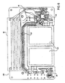
Figure 6 is a top plan view of an exemplary printed circuit (PC) board of an exemplary electronic card; -
Figure 7 is a bottom plan view of the PC board ofFig. 6 ; -
Figure 8 is an exploded, partially cross-sectional view of an exemplary electronic card; -
Figure 9 is partially cross-sectional view of the electronic card ofFig. 8 after it has been assembled; -
Figure 10 illustrates an exemplary wire bond connection between a processor and a PC board; -
Figure 11 illustrates an exemplary broadcaster slot with alignment marks; -
Figure 12 is a top plan view of a broadcaster before it is inserted into the broadcaster slot illustrated inFig. 11 ; -
Figure 13 illustrates an exemplary broadcaster coil; -
Figures 14-16 illustrate exemplary winding patterns of the broadcaster coil ofFig. 13 ; -
Figure 17 is a block diagram of an alternate embodiment, set forth by way of example and not limitation, of a broadcaster assembly; -
Figure 18 is a flow-diagram of a manufacturing process, set forth by way of example and not limitation, for producing electronic cards; -
Figure 19 is a flow-diagram illustrating an exemplary PhaseI manufacturing process 168 ofFig. 18 in greater detail; -
Figure 20 is a flow-diagram illustrating anexemplary programming process 180 ofFig. 19 in greater detail; -
Figure 21 is a flow-diagram illustrating an exemplary "load software and/or data into chip"process 200 ofFig. 20 in greater detail; -
Figure 22 is a flow-diagram illustrating an exemplary PhaseII manufacturing process 170 ofFig. 18 in greater detail; and -
Figure 23 is a flow-diagram illustrating an exemplary PhaseIII manufacturing process 172 ofFig. 18 in greater detail. - As noted, there are a great many applications for electronic cards. One of many applications is to provide security for financial transactions, e.g. financial transactions using transactions cards such as credit cards and debit cards. In the following exemplary embodiments, particular emphasis will be placed on transaction card security, with the understanding that other uses for enhanced electronic security, such as, but not limited to, access control, are within the true spirit and scope of the invention.
-
FIG. 1 is an embodiment of anelectronic card 10, set forth by way of example but not limitation, which includes acard body 11. The card body may be made from a thermoplastic material, such as polyvinylchloride (PVC) in exemplary embodiments, but other materials with sufficient flexibility and durability are also suitable. For example, other thermoplastics can be used, as well as thin metal (e.g. stainless steel). Of course, if a conductive material is used for thecard body 11, adequate electrical insulation from the electrical and/or electronic components must be maintained. Still other materials, such as resins, carbon fibers, organic and non-organic materials, etc. are also suitable for various alternate embodiments. In summary,card body 11 can be made from any suitable material which is strong enough and durable enough to be used as a transaction card. - The exemplary
electronic card 10 has afront surface 12 which is provided with anelectrical interface 16. This is one non-limiting example of a communication port for theelectronic card 10. In other embodiments, theinterface 16 may be eliminated, or additional communication ports may be provided. - The illustrated
electrical interface 16 includes a number of contact pads which, in this example, are formed in a configuration which is compliant with the International Standards Organization "Smart Card"standard ISO 7816. In this exemplary embodiment, the electronic card is usable as a legacy mode Smart Card. Also shown on thefront surface 12 is aninstitution identifier 18, aninstitution number 20, an account number 22, and aclient name 24. The account number is preferably embossed on theelectronic card 10 to provide raised numerals for credit card imprint machines. -
FIG. 2 illustrates aback surface 14 of the exemplaryelectronic card 10. In this exemplary embodiment, amagnetic stripe emulator 26 is provided on theback surface 14 which can be used to communicate with legacy magnetic stripe readers of the prior art. Thestripe emulator 26 is therefore another non-limiting example of a communications port. - The electronic card may also have, for example, an on/off
button 28, an "on"indicator 30, and an "offindicator 32. In this exemplary embodiment, "on"indicator 30 may be a green LED and the "offindicator 32 may be a red LED. Also seen on the exemplary card back 14 are a plurality of account interfaces 34. Eachaccount interface 34 preferably hasaccount indicator LED 36 and anaccount selector switch 38. Eachaccount interface 34 may also have, for example, printed information identifying the account and expiration date. Back surface 14 also has, in this example,instructions 40, aninstitution identifier 41, asignature box 42, and various other printed information. -
FIG. 3 is a block diagram, presented by way of example but not limitation, of the circuitry of exemplaryelectronic card 10. In this example, theelectronic card 10 includes asecure processor 44, ageneral processor 52, and a magnetic stripe emulator 64. Both thesecure processor 44 and thegeneral processor 52 are coupled to theISO 7816interface 16 by abus 48. -
Secure processor 44 is preferably a commercially available Smart Card chip which has various tamper resistant properties such as a secure cryptographic function and tamperresistant storage 46. An exemplary embodiment ofsecure processor 44, given by way of example and not limitation, is a P8WE6032 processor manufactured by Phillips of Germany. Similar devices are manufactured by Hitachi, Infineon, Toshiba, ST and others. As noted previously, in this examplesecure processor 44 is connected electrically to theinterface 16 by abus 48. -
General processor 52 is, in this example, also connected to thebus 48 and, therefore, to both thesecure processor 44 and theinterface 16. Additionally, in this example, thegeneral processor 52 is coupled to thesecure processor 44 by an "I/O 2"line 50. In the current exemplary embodiment,memory 54 is coupled to thegeneral processor 52.General processor 52 is also coupled, in this example, topower source 56,display 58, switches 60, and other I/O 62. - In an alternate embodiment,
general processor 52 communicates with thesecure processor 44 in an ISO7816 compliant mode over thebus 48. In such an embodiment, no other connection to the secure processor is required (e.g. the I/O 2line 50 connection can be omitted). -
Power source 56 is preferably an electrochemical battery disposed within thecard body 11. It may be either a non-rechargeable battery or a rechargeable battery. Ifpower source 56 is a non-rechargeable battery, it should have sufficient capacity to power theelectronic card 10 for its useful life. If thepower source 56 is rechargeable, theelectronic card 10 may be used indefinitely. A rechargeable battery may, for example, be recharged throughinterface 16, by magnetic induction (e.g. through an induction coil or the broadcaster coils), a photovoltaic cell embedded inbody 11, a piezoelectric material embedded in theelectronic card 10, another electrical connector, kinetic recharging mechanisms (e.g. magnets and coils), or other suitable mechanisms. For example, in some situations a rectification of ambient RF energy may provide sufficient energy to power theelectronic card 10, recharge a battery, or store supplemental charge in, for example, a capacitor. - Alternative exemplary embodiments include both a primary and a secondary battery disposed within the card body. For example, a non-rechargeable battery could serve as a primary battery and a rechargeable battery could serve as a secondary battery, or vice versa. These exemplary embodiments are given by way of example and not limitation.
- Since the
power source 56 is embedded in theelectronic card 10, it must be thin. This is because theelectronic card 10, for many applications, must be able to bend within certain ranges. For example, anelectronic card 10 used for transaction card applications must conform to the ISO 7810 standard, which is 85.60 mm (~3370 mils) wide, 53.98 mm (- 2125 mils) tall, and .76 mm (~30 mils) thick. This is often referred to as the "CR80" format, which is roughly 3-1/2" by 2", and fits well into a standard wallet. However, other formats can also be used which are larger, small, or differently configured than the CR80 format. By way of non-limiting example, an electronic card of smaller than CR80 dimensions can be made to fit on, for example, a keychain. - The cards must be somewhat flexible so that they can be used in, for example, insertion-type legacy card readers, so it is also preferable that the power source be somewhat flexibly if it is relatively large in surface area. However, flexibility is not a problem if the battery is relatively small in surface area, or if several smaller batteries are coupled together to form the
power source 56. Also, it is important that thepower source 56 can withstand heat and/or pressure if, for example, heat and/or pressure lamination techniques are used to manufacture theelectronic card 10. - Examples of suitable batteries are manufactured by Varta Microbattery of Ellwangen, Germany and Solicore of Lakeland, Florida. The batteries are preferably electrochemical in nature, although other types of batteries or capacitive storage devices can also be used. Suitable electrochemical batteries can include, by way of example but not limitation, Li-polymer, Ni-MH, lithium, lithium-ion, alkaline, etc.
-
General processor 52 may be, for example, aPIC 16 orPIC 18 microcontroller. In an alternative embodiment,general processor 52 may comprise an ASIC chip. In still further embodiments, general processor may be any form of logic (e.g. a state machine, analog processor, etc.) which performs the desired processing functions. -
Display 58 may include, for example, LED devices as disclosed previously. As another non-limiting example,display 58 is may comprise an LCD display. The LCD display is preferably flexible if it is of a relatively large surface area.Switches 60 can be any form of electrical switches or devices which provides the functionality of switches to provide inputs or controls for theelectronic card 10. Theprocessor 52 may, for example, provide software debouncing algorithms with respect to such switches. Other I/O 62 may comprise any number of alternative I/O subsystems. These may include, by way of example and not limitation, audio, tactile, RF, IR, optical, keyboard, biometric I/O or other I/O. Thesecure processor 44 may also provide I/O by RF or IR in accordance withISO 7816 standards. - Also coupled to
general processor 52, in this exemplary embodiment, is magnetic stripe emulator 64, which allows theelectronic card 10 to be used in a mode which emulates a magnetic stripe card of the prior art. Magnetic stripe emulator 64, in this non-limiting example, is comprised of abuffering circuit 66, which converts digital output fromgeneral processor 52 into a wave form appropriate for magnetic stripe emulation. In this exemplary embodiment, bufferingcircuit 66 includes a conversion circuit which is typically implemented as an RC network. Along with the broadcaster, the RC network forms an RCL network to condition the waveform. RC networks and their equivalents are well known to those skilled in the art. - In this example, magnetic stripe emulator 64 further includes a
broadcaster 68. As used herein, the term "broadcaster" refers to one or more inductive coils which are used to "broadcast" a fluctuating magnetic signal which emulates the movement ("swipe") of a transaction card's stripe past the read head of a magnetic card reader. -
Broadcaster 68 may be electrically coupled to bufferingcircuit 66 and preferably receives two tracks of signal which are converted bybroadcaster 68 into magnetic impulses for magnetic stripe emulation. Alternative embodiments include one, three, four or more tracks.Broadcaster 68 may include one or more electrical coils to convert electrical signal into magnetic impulses. -
Broadcaster 68 of this example may further include one ormore sensors 70, which are electrically coupled togeneral processor 52. These sensors are used to signal togeneral processor 52 that the physical act of swiping thecard body 10 through a legacy card reader has commenced.Sensors 70 also communicate togeneral processor 52 when contact is lost with themagnetic stripe reader 72, which receives and interprets magnetic flux impulses from the broadcaster. - As noted previously, the
electronic card 10 of this example includes anelectrical interface 16. In this example,electrical connectors 16 are used in a manner compliant withISO 7816 to communicate with anISO 7816reader device 74. That is,electronic card 10, in this example, can be used as a legacy Smart Card or as a legacy magnetic stripe transaction card. - When used in a legacy Smart Card mode,
secure processor 44 is powered bybus 48 from a SmartCard reader device 74. Thereader device 74 can be used to program and personalizesecure processor 44 with various information including, by way of example and not limitation, firmware code, account numbers, cryptographic keys, PIN numbers, etc. This information, once loaded intosecure processor 44, preparessecure processor 44 for an operational mode which no longer requires the use ofreader device 74. - In this "independent" mode,
secure processor 44 communicates withgeneral processor 52 and provides services such as cryptographic functions and the dynamic generation of authentication information which is used to communicate viageneral processor 52 and magnetic stripe emulator 64 withmagnetic stripe reader 72. Also in this example, the authentication code may be used only once for a single transaction. Subsequent transactions require new authentication codes to be generated.Secure processor 44 can also send account information and/or DACs via RF and IR. - The
card body 10 continues to be used withreader device 74 and also with magneticstripe reader device 72. The card detects the mode in which it is being used and automatically switches the usage ofbus 48 appropriately for the detected mode of operation. This is achieved inbus arbitrator 76.Bus arbitrator 76 can detect when it is being used withreader device 74 because power is provided byreader device 74 viaelectrical connectors 16 tobus 48. Similarly,bus arbitrator 76 can detect that power is being provided bygeneral processor 52 and switch to the corresponding mode of operation, which servicesgeneral processor 52 and the various I/O devices connected thereto. In yet another exampleoptional bus arbitrator 76 allows for the dynamic communication of bothgeneral processor 52 andsecure processor 44 with each other respectively, and withreader device 74. This requires bus arbitration logic which is well known to those skilled in the art. In a further alterative embodiment,general processor 52 is interposed betweensecure processor 44 andelectrical connectors 16. In this alternative embodiment,general processor 52 acts as a "go-between" or a "front end" forsecure processor 44. - With continuing reference to
FIG. 3 , an exemplarynon-contact communications port 77 may be included as an alternative to or in addition toexemplary communication ports 16 and 64. That is,non-contact communications port 77 may be provided to allow communications without physical contact with a reader. -
Non-contact communications port 77 can be a radio frequency communications port, IR communications port, or any other form of communications which does not require physical contact. Of course other embodiments may be provided with contact communications ports, such ascommunications port 16 and broadcaster. That is, these embodiments are described by way of example and not limitation. - A standard for radio frequency ("RF") communication for Smart Card communications is ISO/IEC 14443, dated 2001. It includes and antenna and RF driver characteristics and defines two types of contactless cards ("A" and "B"), allows for communications at distances up to 10 cm. There have been proposals for ISO 14443 types C, D, E and F that have yet to complete the standards process. An alternative standard for contactless smart cards is ISO 15693, which allows communications at distances up to 50 cm.
-
FIG. 4 illustrates exemplarysecure processor 44 ofFIG. 3 in greater detail.Secure processor 44 of this example is anISO 7816 compliant microcontroller comprisingpower switch 78,security sensors 80, resetgenerator 82,clock input filter 84, CPU 86, interruptsystem 88, andinternal bus 90. Coupled tointernal bus 90 is tamperresistant storage 46, which may be comprised of RAM, EEPROM, etc. Also coupled tobus 90 is co-processor 92, which handles encryption and decryption. In this exemplary embodiment, theco-processor 92 performs TRIPLE-DES encryption and decryption. Also coupled tobus 90 aretimers 94 andROM 96, which is used, for example, for storing firmware forsecure processor 44,UART 98, which is used for serial communications. Also connected tobus 90 is I/O subsystem 100 andrandom number generator 102. -
Secure processors 44 as described above are commercially available from a variety of sources including Philips, Hitachi, Infineon, Toshiba, ST, and others. A suitablesecure processor 44 for use in the disclosed exemplary embodiment is the model P8WE6032 processor made by Philips of Germany. In certain alternate embodiments, thesecure processor 44 can be replaced by a general processor. -
FIG 5 is a schematic ofgeneral processor 52 coupled its associated I/O devices subsystems set forth by way of example and not limitation. As noted above,general processor 52 may be aPIC 16 orPIC 18 microcontroller. For example, thegeneral processor 52 can be aMicrochip LF 77PIC 16 or Microchip LF 4530PIC 18. Alternatives are provided bye Texas Instruments, Atmel, and others. Other general processors may also be used and, in certain alternate embodiments, thegeneral processor 52 can also be a secure processor. - In this exemplary embodiment, two
electrochemical batteries non-rechargeable battery 121A serves as a primary battery, whilerechargeable battery 121B serves as a secondary battery.Battery 121B may be coupled to arecharging apparatus 122, which is shown here as an RF power source. Of course, the induced current is rectified prior to being applied to thebattery 121B. As noted above, there are a number of other suitable recharging apparatus that will be apparent to those skilled in the art. - Preferably,
capacitor assembly 124 is provided in order to provide a smooth source of power without peaks or power dropouts. The capacitor assembly can include one or more capacitors, as illustrated.Capacitor assembly 124 may also be used to smooth the power from a rectifier which may be present in rechargingapparatus 122.Battery 121A,battery 121B, rechargingapparatus 122, andcapacitor assembly 124 are all part ofpower source 56 ofFIG. 3 in this exemplary embodiment. - One or more capacitors, such as the
capacitor assembly 124, can also be used as a charge storage device. That is, a "super capacitor" having a sufficiently high capacitance can significantly supplement the current provided by the electrochemical battery in certain embodiments. For example, a capacitance range of about 1 uF +-10% @ 6.3v is suitable in some embodiments to serve as a super capacitor. This relativelylarge capacitor assembly 124 can be conveniently accomplished, for example, by using ten 0.1uF capacitors connected parallel in order to reduce the size and height of the capacitor. - With continuing reference to
FIG. 5 , atemporary port 125 may provided to assist in the manufacturing process. Optionally, it is provided on a part of a printed circuit board that is removed once the manufacturing operations requiring its use are completed.Temporary port 125 may be used, for example, to load data and programs intogeneral processor 52 and associated EEPROM as well assecure processor 44 and its associated EEPROM.Components 123 may be provided to ensure that the electrical connections togeneral processor 52 have appropriate electrical characteristics, are free of power spikes or power dropouts, etc. -
General processor 52 is, in the present example, connected to a number of switches including on/offswitch 28 and account selector switches 38. Also connected togeneral processor 52 are a number of light emitting diodes ("LEDs") including a "power-on"indicator 30, a "power-off"indicator 32, and "account-on"indicators 36. These various LEDs and switches comprise a human/computer interface with theelectronic card 10. Of course, there are many alternates or additions to theelectronic card 10 and to devices communicating with theelectronic card 10 which are also helpful human/computer interfaces. By way of further example but not limitation, theelectronic card 10 may include an LCD screen (with or without a touch panel), audio I/O, voice recognition, and various other alternatives that will be apparent to those of skill in the art. - In this example, an
RC buffering circuit 66 is coupled togeneral processor 52 and converts (in conjunction with thebroadcaster 68 and/or other components) square wave type signals emanating fromgeneral processor 52 into wave forms which emulate the magnetic signals ("dynamic magnetic flux") provided by a magnetic stripe transaction card passing through a reader. Wave forms are communicated electrically tobroadcaster 68 which converts the electrical signals into a dynamic magnetic field which simulates the passing of a card with a magnetic stripe through a magnetic stripe reader. Theelectronic card 10 may be moving or stationary, and the varying magnetic field broadcasted by thebroadcaster 68 will emulate the varying magnetic field created by a magnetic stripe of a conventional transaction card moving past a read head. The magnetic signal created by the broadcaster therefore tends to be substantially uniform along its length. -
Sensors 70 provide signals togeneral processor 52 to indicate that the card has made physical contact with the reader.Sensors 70 may take various forms including physical switches, pressure sensors or other alternatives which will be apparent to those of skill in the art.Broadcaster 68 achieves its waveform subsequent to the activation of one ormore sensors 70. - Four
exemplary coils FIG. 5 . Mare particularly, in this exemplary embodiment, thebroadcaster 68 includes a "track one"coil 128, a "track two"coil 130, a "track one cancellation"coil 132 and a "track two cancellation"coil 134. In this exemplary embodiment, the track onecoil 128 and the track twocoil 130 are preferably positioned on the card for optimal contact with magnetic read head of magnetic stripe reader device 72 (seeFig. 3 ). That is, the track onecoil 128 is preferably positioned equidistant from and interposed between the track twocoil 130 and the track twocancellation coil 134. - Since the magnetic field from the track two
coil 130 may interfere with the magnetic field of the track onecoil 128, the track twocancellation coil 134 is provided to "cancel" this "cross talk" effect. By "cancel" it is meant that the cross talk is at least significantly reduced. The magnetic field generated by the track twocancellation coil 134 is the inverse of that of the track twocoil 130 thus reduces the effect of the track twocoil 130 magnetic field of track onecoil 128. Similarly, the track twocoil 130 is, in this example, equidistant from and interposed between track onecoil 128 and track onecancellation coil 132. Reduction of the cross talk effect of the track onecoil 128 is provided by the track onecancellation coil 132. The broadcaster coils 128-134 andsensors 70 comprisebroadcaster 68 in this exemplary embodiment. - In an alternative embodiment, cancellation coils 134 and 132 are not provided, but rather, the electrical signals provided to these coils are modified in such a manner that the interfering magnetic fields provide appropriate magnetic input to magnetic
stripe reader device 72. This may be achieved through the use of an ASIC, digital signal processor (DSP), or by other instrumentalities. Optionally, the positions of these twobroadcaster coils 126 may be offset from their positions in the previously described embodiment to provide the appropriate effect. Alternatively, cancellation can be achieved through mechanical shielding with nano materials that could shield the broadcast data between the two adjacent coils. These various exemplary embodiments are given by way of example and not limitation. Alternatives to the embodiments show inFIG. 5 will be apparent to those of skill in the art. - Furthermore, a digitally synthesized signal may be applied to the
broadcaster 68 which could reduce or eliminate the need for signal conditioning circuitry such as the RC circuit and/or for the need for cancellation coils. The digitally synthesized signal may be accomplished, for example, in thegeneral processor 52, in a DSP, or in other circuitry, as will be appreciated by those skilled in the art. -
FIG. 6 is a top plan view of an exemplary printed circuit (PC)board 136. Preferably,PC board 136 is a "flex" board so that theelectronic card 10 is compliant with the aforementioned ISO 7810 standard for flexibility.PC board 136 is provided with conductive traces, such astraces 137, and supports various electronic components such asprocessors PC board 36 also provides space for thebroadcaster 66 and one or moreelectrochemical batteries 121. This exemplary embodiment is provided by way of example and not limitation. - As noted previously, the thickness (or height, when the card is taken in cross-section) for an
electronic card 10 made to ISO 7810 standard dimensions is only about 30 mils. Therefore, it is important that the various internal components of theelectronic card 10 be thin, flat, and substantially coplanar. By way of example and not limitation, thedigital processor 52 should be thin and flat, with a first substantially planar surface and a substantially opposing second substantially planar surface. It should also define a first maximum surface area. By way of further example but not limitation, theelectrochemical battery 121 should have a first substantially planar surface and as substantially opposing second substantially planar surface, and should define a second maximum surface area. A theoretical plane through the center of thedigital processor 52 should be substantially coplanar with a theoretical plane through the center ofbattery 121 so that the desired thinness of theelectronic card 10 may be achieved. - The word "substantially" is used herein to mean approximately. For example, a substantially planar surface is at least approximately flat. Minor imperfections, steps, bumps or curvatures to the major surfaces are still considered to be "substantially planar", and do not have to be applied to the entire surface. "Substantially opposing surfaces" are generally facing each other and are at least approximately parallel.
- By "substantially co-planar" it is meant that theoretical center planes are at least close together and approximately parallel. Of course, the center plane of
processor 52 could be above or below the center plane ofbattery 121 and the two components could still be considered "substantially co-planar" as long as the desired thinness of theelectronic card 10 can be maintained. For example, theprocessor 52 andbattery 121 can still be considered coplanar as long as there is any plane generally parallel to the major surfaces of these components which intersects both of the components. If, for example, thebattery 121 is 16 mils high and theprocessor 52 is 10 mils high in cross section, the center planes of the components could be separated by as much as 8 mils and they would still be considered to be "substantially co-planar." -
FIG. 7 is a bottom plan view ofexemplary PC board 136.PC board 136 is again provided with a number oftraces 137, as well as space for thebroadcaster 66 andbatteries 121. Also shown isinterface 16 which is geometrically positioned to coincide with the position ofsecure processor 44. These exemplary embodiments are given by way of example and not limitation. -
PC board 136 may be, for example, a multilayer PC board. For example, the top of thePC board 136 as seen inFig. 6 may be a first or top layer, and the bottom of the PC board as seen inFig. 7 may be a second or bottom layer. The two layers may be adhered together, or there may be other intermediate layers. Each layer includes an insulating substrate made, for example, from a PVC material, and may include conductive traces, pads, and other structures. As noted above, it is desired that the PC board be flexible to help theelectronic card 10 meet the ISO 7810 standards for flexibility. -
FIG. 8 is an exploded, partially cross-sectional view ofelectronic card 10. Abottom cover 140 has, in this example, a maximum height of about 25 mils. It should be noted that thebottom cover 140 is contoured on itsupper surface 141 to fit the contours of the PC board, battery, and/or components attached to the bottom of the PC board or the like. ThePC board 136, in this example, has a height of about 6 mils, which makes it thin an flexible.General processor 52 is shown mounted onPC board 136 and encapsulated by material 144 (e.g. an epoxy encapsulant). Also shown issecure processor 44 similarly encapsulated bymaterial 144. Also mounted onPC board 136 are the various components ofbattery 121. - With continuing reference to
FIG. 8 , an exemplary embodiment ofbattery 121 has a height of 16 mils. Also shown inFIG. 8 isbroadcaster 68 which coincides laterally withbattery 121 in this embodiment and thus occupies the overlapping space in this cross-section diagram.Broadcaster 68 as shown in this exemplary embodiment has a height of about 20 mils. Also mountedPC board 136 are account selector switches 38, "on"indicator 30, and "off"indicator 32.Account indicators 34 coincide laterally with onindicator 30 and, therefore, occupy overlapping space in this cross-section view. Cover 146 is shown with a height of 5 about mils. When assembled, theelectric card 30 is therefore approximately 30 mils, which is ISO 7810 compliant. The exemplary embodiments shown inFIG. 8 are given by way of example and not limitation, and dimensions can vary, as will be appreciated by those of skill in the art. -
FIG. 9 is a partial cross-sectional view ofelectronic card 10 after it has been assembled. The various exemplary components are shown with the various layers in compact form as with a finishedelectronic card 10.Covers epoxy adhesive 147 is used to encapsulate the electrical and electronic components (other than those which must be exposed) and to hold the assembly together. Thecovers electronic card 10 compliant with the dimensions set forth by ISO 7810 standard. Importantly, the thickness T should not be much greater than about 30 mils so that it works properly with legacy card readers. Other embodiments provide electronic cards of different sizes and formats. -
FIG. 10 is a detailed elevational view of a wire bond connecting a processor die 56 toPC board 136. This exemplary embodiment allows for a low profile as is advantageous due to the severe size constraints imposed by the thickness standards forelectronic card 10.Die 56 is mounted onPC board 136 using an adhesive orother bonding material 158 which forms the physical connection betweenprocessor 56 and printedcircuit board 136.Wire 148 electrically connects abonding pad 160 ofprocessor 56 with abonding pad 160 ofPC board 136. - It is very important to have a low loop-height "d" for the
wire 148. Conventional wire bonding techniques bond a wire first to the processor and then to the substrate, resulting in a very high loop height. A high loop height is unacceptable for electronic cards, which must be made very thin. Also, a high loop height creates a reliability problem due to bending and torsional stresses to which the electronic card may be subjected. - In accordance with an aspect of this exemplary embodiment, a reverse bonding process is used where the
wire 148 is first attached to thePC board 136 and then attached to theprocessor 56. This results in a short loop height "d", which is preferably less than 5 mils and is more preferably 2-4 mils or less. As a result, the total height of the loop is equal to d + D, where "D" is the height of the top surface of theprocessor 56 above the top surface of thePC board 136. In the present example, the processor die 56 is about 9-10 mils, and the adhesive is about 1-2 mils, resulting in a height D of about 10-12 mils. If the loop height d is in the range of 2-4 mils, the total height of the loop above the top surface of the PC board is in the range of 12-16 mils, in this example. - The low loop height also helps with the aforementioned bending and torsional stresses to which the electronic card may be subjected. For example, with a loop height of preferably less than 5 mils, more preferably less than 4 mils, and most preferably about 2 mils or less, 7-10 grams of pull-strength on the wire can be achieved.
- In another embodiment, the
processor 56 is attached to the PC board in a flip-chip fashion. Techniques for attaching dies to substrates in a flip-chip fashion are well known to those skilled in the art. -
FIG. 11 shows areceptacle 160 inPC board 136 forbroadcaster 68.Broadcaster 68, in this example, is inserted intoreceptacle 160 at a late stage of the manufacturing process and is then electrically connected to contactpads 161. When mountingbroadcaster 68 insidereceptacle 160 it is important to achieve a high degree of geometric alignment so thatbroadcaster 68 can be properly aligned with the read head of a card reader.Guides 162, visible through holes inbroadcaster 68, are provided to aid in this physical alignment process. When insertingbroadcaster 68 intoslot 160, it is preferable that the alignment guides 162 closely align with the holes inbroadcaster 68. Optical microscopes may be used to help with this process. Of course, these exemplary embodiments are given by way of example and not limitation, and other alignment techniques are suitable. -
FIG. 12 showsbroadcaster 68 in its final form before it is inserted intoslot 160. Track onecoil 128 and track twocoil 130 are aligned to make optimal contact with magneticstripe reader device 72. Track onecancellation coil 132 and track twocancellation coil 134 are positioned appropriately to perform their function of cancellation cross talk between track onecoil 128 and track twocoil 130.Sensors 70 are shown here as trip switches which detect the event ofelectronic card 10 being passed through magneticstripe reader device 72. - These exemplary embodiments are given by way of example and not limitation. Alternatives for the composition and configuration of
broadcaster 68 will be apparent to those of skill in the art. For example, alternative embodiments which do not include cancellation coils 132 and 134 are contemplated as are other alternative embodiments. As another non-limiting example, certain embodiments have only a single track coil. -
FIG. 13 shows anexemplary broadcaster coil 128 in greater detail. The other broadcaster coils 130-134 can be of similar or identical design, or can be of different designs in alternated embodiments. In this embodiment, awire 164 is wound around aferromagnetic core 166. Thewire 164 can be made from, for example, copper or aluminum, alloys thereof, etc. Thewire 164 may be insulated, or thecore 166 may be insulating or insulated to prevent the windings ofwire 164 from shorting out. - In an exemplary embodiment,
broadcaster core 166 is composed of a material called "HyMu 80", with favorable magnetic properties, which is commercially available from National Electronic Alloys Inc. A single strand ofcopper wire 164 is wound aroundbroadcaster core 166 at regularly spaced intervals, e.g. with a constant pitch "P." In an exemplary embodiment, the pitch of the wire coil is about 4.8 mils. This exemplary embodiment is given by way of example and not limitation, as other pitches and variable pitches are suitable in certain embodiments. -
FIG. 14 shows an exemplary spacing ofwire 164 coiled aroundcore 166.FIG. 14 shows a regular spacing between each coil wind ofcopper wire 164 with a constant pitch. This is a preferred embodiment although other embodiments may be used. -
FIG. 15 shows a somewhat irregular winding. Even though some errors may be introduced during the winding process, it is possible to still use the resulting broadcaster coils despite some error in the winding process as shown inFIG. 15 . The pitch may also be varied to modify the magnetic flux pattern. However, if too much error is introduced during the manufacture ofbroadcaster coil 126, then the coil may be inoperative. It has been found that if the variation in pitch is too great, errors may be introduced into the dynamic magnetic field produced by the coils, resulting in improper operation of the emulator embodiment ofelectronic card 10. -
FIG 16 depicts an example of too much error in the positions of the coil windings ofbroadcaster coil 126. It is important to note that many variables exist which effect the threshold of operability and that thebroadcaster coil 126 should be tested in order to ensure proper quality. It may not be necessary to test each and every coil but a sampling ofbroadcaster coils 126 should be tested to ensure that a manufactured batch of coils is operative.FIGS. 14 through 16 are given as examples of alternative coil windings and should not be construed in a limiting way. - The aforementioned embodiments for the coils teach winding a wire around a ferromagnetic core. In alternate embodiments, the coils can be made in other fashions. For example, coils can be made with various deposition, patterning, and etching techniques. As will be appreciated by those skilled in the art, a ferromagnetic core can be coated with an insulating film, and then coated with a conductive (usually metal) layer of, for example, copper or aluminum or alloys thereof by, by way of example and not limitation, sputtering and nano-sputtering techniques. A mask can then be applied to the conductive layer to define the coil, and portions of the conductive layer can be etched away to provide the windings. The mask can be made photolithographically, by spraying with, for example, ink-jet technologies, or by other techniques well known to those skilled in the art. The etching can be accomplished with an acid which attacks the conductive layer but which is stopped by the insulating film. This method of coil production may have advantages in high-volume manufacturing situations.
- For example, a ferromagnetic coil can be prepared and cleaned. An insulating and/or etch stop layer can be applied by a variety of techniques including, but not limited to, dipping, spraying, coating, sputtering, CVD, etc. A metal or other conductive layer can then be applied, again by a variety of techniques including, but not limited to, dipping, spraying, coating, sputtering, CVD, etc. A mask layer can be applied as a photolithographic material, by painting, printing, spraying, stenciling, etc., as will be appreciated by those skilled in the art. The etching of the conductive layer through the mask layer can be accomplished by a variety of techniques including, but not limited to, dipping, spraying, immersing, and plasma etching techniques. The mask layer is then removed, and a passifying layer may be applied to protect the coil assembly.
- As will be appreciated by those skilled in the art, there are other ways to produce the effects of the "coils" of the broadcaster. For example, magnetic material can be lithographically sputtered to create the broadcaster coil effect. There are a variety of mass production techniques such as those noted above, by example, which will be apparent to those skilled in the art of semiconductor and micro-machine manufacturing.
-
FIG. 17 shows an alternate embodiment which allows a broadcaster 68' to operate without cancellation coils. Track onecoil 128 and track twocoil 130 are shown within broadcaster 68'. Buffering circuit 66', in this embodiment, is designed to perform cancellation prior to emitting the wave forms to track onecoil 128 and track twocoil 130. The wave forms are adjusted in such a way that the overall cross talk effect between track onecoil 128 and track twocoil 130 produces the desired magnetic flux. This alternate embodiment cancels cross talk by correcting the wave forms so that the appropriate signals to be received by magneticstripe reader device 72. In this embodiment, buffering circuit 66' may be an ASIC, a DSP, or other appropriate components for signal processing.Sensors 70 are present in this embodiment ofbroadcaster 68. - In one exemplary alternative embodiment,
general processor 52 is comprised of an ASIC chip, which optionally includes one or more other components ofexemplary transaction card 10. For example, the ASIC assumes the role of bufferingcircuit 66 as well as the duties of other components associated withgeneral processor 52 in the previously disclosed embodiments. Further, the ASIC embodiment could, for example, produce adjusted waveforms fortrack 1coil 128 andtrack 2coil 130 so that it is not necessary to includetrack 1cancellation coil 132 ortrack 2cancellation coil 134. For example, the ASIC could apply a correction to the amplitude and phase of the waveform oftrack 1coil 128 because of the anticipated effect of magnetic flux interference fromtrack 2coil 130. Likewise, a correction would be applied to the waveform fortrack 2coil 130, to cancel the effect oftrack 1coil 128. - Note that the corrections applied to the waveform may vary with time because the interference from the opposing
broadcaster coil 126 may vary with time (at different parts of the waveform). Thus, the correction constitutes two new waveforms for the two respective broadcaster coils 128 of this exemplary embodiment. Note also that the correction wavefonn for a givenbroadcaster coil 128 will itself cause interference with the opposingbroadcaster coil 128. - In some exemplary embodiments, an additional correction is applied to compensate for the effect of the previous correction. In still further exemplary embodiments, one or more additional corrections are applied until the diminishing effect of interference becomes negligible as the series converges. Note that these corrections are performed in a computational manner before the corresponding portions of the waveforms reach the
broadcaster 68. - In a further alternative embodiment, the crosstalk cancellation is performed in a linear RC circuit which outputs corrected waveforms to track 1
coil 128 andtrack 2coil 130. This RC circuit could be disposed within the exemplary ASIC described above or external to the ASIC. Again, this embodiment is provided by way of example and not limitation. -
FIG. 18 shows a manufacturing process for producingelectronic card 10. In anoperation 168, a first phase of the manufacturing process is performed. During this process, the various components are mounted and programmed. Anoperation 170 continues this process of manufacture in a second phase by installing additional components such as thebroadcaster 68 andbattery 121. Finally, the manufacturing process is completed in a third phase by anoperation 172 which performs an epoxy fill. -
FIG. 19 shows thefirst phase 168 of manufacturing in greater detail. In anoperation 174 technology components are mounted to the surface of their associated printed circuits. In anoperation 176, the die is attached. Previously described wiring bonding process may be performed in anoperation 178 to electrically connect the die to the printed circuit board. Then, in aprogramming step 180,secure processor 44 andgeneral processor 52 are programmed with various data and programs necessary for the operation ofelectronic card 10. Anoperation 182 performs a functional test prior to encapsulation to ensure that the programming was successfully loaded and the various electrical connections were secure. - In a
decision step 184, it is determined whether or not the functional test has been passed. If it is not, then, control passes to anoperation 186, wherein the problem which causes the failure is determined. Then, in anoperation 188, the problem is reworked in anoperation 188 and, then, control passes again toprogramming step 180. If, on the other hand, indecision step 184 it is determined that the functional test is passed, then, an encapsulation process is performed instep 190. Once encapsulation is completed, the first phase of manufacture is completed. The process shown here is exemplary and as will be apparent to those of skill in the art, many alternative embodiments may be used. That is, this process is described by way of example and not limitation. -
FIG. 20 describes theprogramming operation 180 in greater detail. The operation is commenced in anoperation 192 and continues in anoperation 194 whereinelectronic card 10 is attached to a test rig. A test program is launched on the test rig in anoperation 196. The purpose of this test program is to load data and programs on to the technology components ofelectronic card 10, such assecure processor 44 andgeneral processor 52. In anoperation 198, the test program is initialized. This may involve loading various parameters and settings from a file or obtaining them from a user. Anoperation 200 performs the actual loading of the software and data on to the technology components aforementioned. Then, in anoperation 202, the process is concluded. This process is shown in terms of its exemplary embodiments and should not be construed in a limiting way. -
FIG. 21 showsoperation 200 ofFIG. 20 in greater detail. This operation is used to load software and data into the technology components ofelectronic card 10. The operation is commenced with anoperation 204 and continues with anoperation 206, which opens a file containing the code and data to be loaded. Then, in anoperation 208, an address range is obtained for a specific block of data. This address range is used when communicating withsecure processor 44 andgeneral processor 52 to specifically identify the locations in EEPROM where this particular block of data should be stored. As is understood by those skilled in the art, the data could comprise programs. In anoperation 210, a message is formatted which contains a block of data and the address information. Then, in anoperation 212, the message is sent. Anoperation 214 receives and records status information. Adecision operation 216 determines whether or not the last block has been sent or if, for other reasons, the process should be terminated, such as in the case of an error. If it is determined that the loading operation should continue, control passes back tooperation 208. If inoperation 216 it is determined that the process should terminate, control passes to an operation 218 which reports the status of the loading operation and, then, the process is concluded in anoperation 220. -
FIG. 22 shows the second phase ofmanufacturing operation 170 in greater detail. The process starts in an operation 222 and continues in anoperation 224, which performs a functional test on the device. In adecision operation 226, it is determined whether or not the functional test has been passed and, if it has not, control passes to anoperation 228 where corrective action is taken. Control then passes to back tooperation 224. If, inoperation 226, it is determined that the functional test has been passed, control passes tooperation 228 wherein the dome switch is taped and the via switch is soldered. Then, in anoperation 230,broadcaster 68 is installed in the slot provided for it withinelectronic card 10. Then, in anoperation 232,battery 121 is installed. In anoperation 234, the assembly is inspected and tested. If it is determined inoperation 234 that the assembly is not functioning properly, control passes to anoperation 236 where corrective action is taken. Control then passes back tooperation 234. If it is determined inoperation 234 that the assembly is working correctly, control passes to anoperation 236 which ends the process. These exemplary embodiments are given by way of example and not limitation. -
FIG. 23 describes thethird phase 172 of the manufacturing process. It begins with anoperation 238 and continues with anoperation 240 wherein the assembly ofelectronic card 10 is filled with epoxy, laminated and tested. Then, in anoperation 242, various measurements of the assembly are taken and, in adecision step 244, it is determined whether or not the assembly needs to be reworked. If it is determined inoperation 244 that the assembly needs to be reworked, corrective action is taken inoperation 246, and control is passed back tooperation 244. If it is determined inoperation 244 that the assembly does not require reworking, control is passed tooperation 246, which concludes the process. - The above described exemplary manufacturing process, and variants thereof, may be used to a variety of embodiments of
transaction card 10. For example, a variant of the manufacturing process uses photolithography techniques well known to those skilled in the art to producebroadcaster 68. This method avoids the use of coil winding, which may save time and money when manufacturingtransaction card 10 in large numbers. - Another variant of the process would use the "flip chip" method well known to those skilled in the art to mount one or more technology components such as
general processor 52. Optionally, this variant would include the use of an ASIC asgeneral processor 52. This embodiment is given by way of example and not limitation. - An alternative exemplary embodiment of
non-contact communication port 77 ofFig. 3 comprises a WiFi device or equivalent, which allows this embodiment oftransaction card 10 to communicate with the internet independently of a card reader. By non-limiting example, the WiFi 802.11b and 802.11g protocols may be used. The card could periodically download and upload information, and also perform transactions in response to user input. Information from the internet could be displayed to the user and interaction with the World Wide Web would also be possible in certain embodiments. This embodiment would preferably include an LCD display or equivalent and a touch screen or equivalent. This embodiment is given by way of example and not limitation. - Although various embodiments have been described using specific terms and devices, such description is for illustrative purposes only. The words used are words of description rather than of limitation. It is to be understood that changes and variations may be made by those of ordinary skill in the art without departing from the spirit or the scope of the present invention, which is set forth in the following claims. In addition, it should be understood that aspects of various other embodiments may be interchanged either in whole or in part. It is therefore intended that the claims be interpreted in accordance with the true spirit and scope of the invention without limitation or estoppel.
- The industrial applicability of the present invention is an improved electronic card for financial and other purposes and manufacturing methods for making same.
Claims (10)
- An electronic card for use with an ISO 7816 reader device and for use with a magnetic stripe reader, the electronic card comprising a flexible printed circuit board having:a general processor and a secure processor attached thereto;at least one battery coupled thereto; anda top cover and a bottom cover,said printed circuit board, said processors and said battery sandwiched between said top cover and said bottom cover,wherein:the electronic card (10) comprises a human/computer interface;the general processor (52) is coupled with a magnetic stripe emulator (64);the electronic card (10) includes an electrical interface (16) coupled to the general processor and secure processor by a bus (48);the electronic card has a first mode in which it is used as a smart card with the electrical connectors (16) of the electrical interface (16) used in a manner compliant with ISO 7816 to communicate with the ISO 7816 reader device (74);the electronic card has a second mode in which it is used as a magnetic stripe transaction card with the secure processor (44) communicating with the general processor (52) and communicating via the general processor (52) and the magnetic stripe emulator (64) with the magnetic stripe reader;the electronic card further comprises a bus arbitrator (76);the bus arbitrator (76) can detect whether the electronic card is being used in the first mode or the second mode and thereby automatically switch the usage of the bus (48) appropriately for the detected mode;the bus arbitrator (76) can detect the first mode based on power provided via electrical connectors (16) to bus (48);
andthe bus arbitrator (76) can detect the second mode based on power provided by general processor (52). - An electronic card as recited in claim 1 wherein the flexible printed circuit board includes a plurality of traces, wherein said general processor (52) is electrically coupled to traces of said circuit board.
- An electronic card as recited in claims 1-2 wherein at least said general processor (52) is encapsulated.
- An electronic card as recited in claims 2-3 wherein at least one of said top cover and said bottom cover are contoured to fit over said flexible circuit board, general processor (52) and battery.
- An electronic card as recited in claims 2-4 further comprising a switch coupled to said flexible circuit board.
- An electronic card as recited in claims 2-5 further comprising an indicator coupled to said flexible circuit board.
- An electronic card as recited in claims 2-6 wherein said general processor (52) is electrically coupled to traces of said circuit board in a flip-chip fashion.
- An electronic card as recited in claims 2-6 wherein said general processor (52) is electrically coupled to traces of said circuit board by wires bonded at a first end to said circuit board and bonded at a second end to said processor.
- An electronic card as recited in claims 1-8 further comprising a capacitor coupled to said battery to provide additional charge storage.
- A method for making an electronic card for use with an ISO 7816 reader device and for use with a magnetic stripe reader, the electronic card comprising
a flexible printed circuit board having:attaching a general processor and a secure processor to said printed circuit board;coupling at least one battery to said printed circuit board;encapsulating at least said one processor;making a top cover and a bottom cover;sandwiching said printed circuit board, said processors and said battery between said top cover and said bottom cover;
andcoupling the general processor (52) with a magnetic stripe emulator (64),wherein:the electronic card (10) comprises a human/computer interface:the electronic card (10) includes an electrical interface (16), coupled to the general processor and secure processor by a bus (48);the electronic card has a first mode in which it is used as a smart card with the electrical connectors (16) of the electrical interface (16) used in a manner compliant with ISO 7816 to communicate with the ISO 7816 reader device (74); andthe electronic card has a second mode in which it is used as a magnetic stripe transaction card with the secure processor (44) communicating with the general processor (52) and communicating via the general processor (52) and the magnetic stripe emulator (64) with the magnetic stripe reader;the electronic card further comprises a bus arbitrator (76);the bus arbitrator (76) can detect whether the electronic card is being used in the first mode or the second mode and thereby automatically switch the usage of the bus (48) appropriately for the detected mode;the bus arbitrator (76) can detect the first mode based on power provided via electrical connectors (16) to bus (48);
andthe bus arbitrator (76) can detect the second mode based on power provided by general processor (52).
Applications Claiming Priority (3)
| Application Number | Priority Date | Filing Date | Title |
|---|---|---|---|
| US67538805P | 2005-04-27 | 2005-04-27 | |
| US11/391,719 US20080148394A1 (en) | 2005-03-26 | 2006-03-27 | Electronic financial transaction cards and methods |
| PCT/US2006/016842 WO2006116772A2 (en) | 2005-04-27 | 2006-04-27 | Electronic cards and methods for making same |
Publications (3)
| Publication Number | Publication Date |
|---|---|
| EP1882229A2 EP1882229A2 (en) | 2008-01-30 |
| EP1882229A4 EP1882229A4 (en) | 2012-08-01 |
| EP1882229B1 true EP1882229B1 (en) | 2014-07-23 |
Family
ID=37215598
Family Applications (1)
| Application Number | Title | Priority Date | Filing Date |
|---|---|---|---|
| EP06752097.3A Not-in-force EP1882229B1 (en) | 2005-04-27 | 2006-04-27 | Electronic cards and methods for making same |
Country Status (4)
| Country | Link |
|---|---|
| US (9) | US20070034700A1 (en) |
| EP (1) | EP1882229B1 (en) |
| KR (1) | KR20080003006A (en) |
| WO (1) | WO2006116772A2 (en) |
Families Citing this family (242)
| Publication number | Priority date | Publication date | Assignee | Title |
|---|---|---|---|---|
| US7809642B1 (en) | 1998-06-22 | 2010-10-05 | Jpmorgan Chase Bank, N.A. | Debit purchasing of stored value card for use by and/or delivery to others |
| US6615189B1 (en) * | 1998-06-22 | 2003-09-02 | Bank One, Delaware, National Association | Debit purchasing of stored value card for use by and/or delivery to others |
| US7660763B1 (en) | 1998-11-17 | 2010-02-09 | Jpmorgan Chase Bank, N.A. | Customer activated multi-value (CAM) card |
| US7058817B1 (en) | 1999-07-02 | 2006-06-06 | The Chase Manhattan Bank | System and method for single sign on process for websites with multiple applications and services |
| US8793160B2 (en) | 1999-12-07 | 2014-07-29 | Steve Sorem | System and method for processing transactions |
| US6615190B1 (en) * | 2000-02-09 | 2003-09-02 | Bank One, Delaware, National Association | Sponsor funded stored value card |
| US7103556B2 (en) * | 2000-11-02 | 2006-09-05 | Jpmorgan Chase Bank, N.A. | System and method for aggregate portfolio client support |
| US8849716B1 (en) | 2001-04-20 | 2014-09-30 | Jpmorgan Chase Bank, N.A. | System and method for preventing identity theft or misuse by restricting access |
| US7313546B2 (en) | 2001-05-23 | 2007-12-25 | Jp Morgan Chase Bank, N.A. | System and method for currency selectable stored value instrument |
| WO2002099598A2 (en) | 2001-06-07 | 2002-12-12 | First Usa Bank, N.A. | System and method for rapid updating of credit information |
| US7266839B2 (en) | 2001-07-12 | 2007-09-04 | J P Morgan Chase Bank | System and method for providing discriminated content to network users |
| US7860789B2 (en) | 2001-07-24 | 2010-12-28 | Jpmorgan Chase Bank, N.A. | Multiple account advanced payment card and method of routing card transactions |
| US8020754B2 (en) | 2001-08-13 | 2011-09-20 | Jpmorgan Chase Bank, N.A. | System and method for funding a collective account by use of an electronic tag |
| US7987501B2 (en) | 2001-12-04 | 2011-07-26 | Jpmorgan Chase Bank, N.A. | System and method for single session sign-on |
| US7899753B1 (en) | 2002-03-25 | 2011-03-01 | Jpmorgan Chase Bank, N.A | Systems and methods for time variable financial authentication |
| US20180165441A1 (en) | 2002-03-25 | 2018-06-14 | Glenn Cobourn Everhart | Systems and methods for multifactor authentication |
| US8751391B2 (en) | 2002-03-29 | 2014-06-10 | Jpmorgan Chase Bank, N.A. | System and process for performing purchase transactions using tokens |
| US20040210498A1 (en) | 2002-03-29 | 2004-10-21 | Bank One, National Association | Method and system for performing purchase and other transactions using tokens with multiple chips |
| US7809595B2 (en) | 2002-09-17 | 2010-10-05 | Jpmorgan Chase Bank, Na | System and method for managing risks associated with outside service providers |
| US7058660B2 (en) * | 2002-10-02 | 2006-06-06 | Bank One Corporation | System and method for network-based project management |
| US20040122736A1 (en) | 2002-10-11 | 2004-06-24 | Bank One, Delaware, N.A. | System and method for granting promotional rewards to credit account holders |
| US8301493B2 (en) | 2002-11-05 | 2012-10-30 | Jpmorgan Chase Bank, N.A. | System and method for providing incentives to consumers to share information |
| US8306907B2 (en) | 2003-05-30 | 2012-11-06 | Jpmorgan Chase Bank N.A. | System and method for offering risk-based interest rates in a credit instrument |
| US8684267B2 (en) * | 2005-03-26 | 2014-04-01 | Privasys | Method for broadcasting a magnetic stripe data packet from an electronic smart card |
| US8226001B1 (en) | 2010-06-23 | 2012-07-24 | Fiteq, Inc. | Method for broadcasting a magnetic stripe data packet from an electronic smart card |
| US7793851B2 (en) * | 2005-05-09 | 2010-09-14 | Dynamics Inc. | Dynamic credit card with magnetic stripe and embedded encoder and methods for using the same to provide a copy-proof credit card |
| US20080035738A1 (en) * | 2005-05-09 | 2008-02-14 | Mullen Jeffrey D | Dynamic credit card with magnetic stripe and embedded encoder and methods for using the same to provide a copy-proof credit card |
| US7401731B1 (en) | 2005-05-27 | 2008-07-22 | Jpmorgan Chase Bank, Na | Method and system for implementing a card product with multiple customized relationships |
| US8899487B2 (en) * | 2005-08-18 | 2014-12-02 | Ivi Holdings Ltd. | Biometric identity verification system and method |
| US20100265037A1 (en) | 2005-09-08 | 2010-10-21 | Cardlabs Aps | Dynamic transaction card and a method of writing information to the same |
| US7818264B2 (en) * | 2006-06-19 | 2010-10-19 | Visa U.S.A. Inc. | Track data encryption |
| US20080126260A1 (en) * | 2006-07-12 | 2008-05-29 | Cox Mark A | Point Of Sale Transaction Device With Magnetic Stripe Emulator And Biometric Authentication |
| US20080126212A1 (en) * | 2006-07-12 | 2008-05-29 | Cox Mark A | Method of Marketing Credit Card Accounts and Point-Of-Sale Payment Devices |
| AU2007314354A1 (en) * | 2006-10-31 | 2008-05-08 | Solicore, Inc. | Powered authenticating cards |
| WO2008147457A1 (en) * | 2006-11-22 | 2008-12-04 | Cox Mark A | Point0f sale transaction device with magnetic stripe emulator and biometric authentication |
| KR100900476B1 (en) * | 2007-02-16 | 2009-06-03 | 삼성전자주식회사 | Mobile communication device and battery recharge method thereof |
| US8002193B2 (en) * | 2007-03-12 | 2011-08-23 | Visa U.S.A. Inc. | Payment card dynamically receiving power from external source |
| BRPI0809049A2 (en) * | 2007-03-23 | 2014-09-02 | Innovatier Inc | ELECTRONIC CARD AND RESPECTIVE MANUFACTURING METHOD |
| US20080319912A1 (en) * | 2007-06-22 | 2008-12-25 | Faith Patrick L | Powering financial transaction token with onboard and external power source |
| US9111122B2 (en) * | 2007-07-02 | 2015-08-18 | Freescale Semiconductor, Inc. | Asymmetric cryptographic device with local private key generation and method therefor |
| MX2008014010A (en) * | 2007-11-02 | 2009-05-26 | Citicorp Credit Services Inc | Methods and systems for managing financial institution customer accounts. |
| US8011577B2 (en) * | 2007-12-24 | 2011-09-06 | Dynamics Inc. | Payment cards and devices with gift card, global integration, and magnetic stripe reader communication functionality |
| WO2009097604A1 (en) * | 2008-01-31 | 2009-08-06 | Priva Technologies Inc. | System and method for self-authenticating token |
| US8141780B2 (en) | 2008-02-23 | 2012-03-27 | Cedar Ridge Research Llc | System and method for data card emulation |
| GB0805780D0 (en) * | 2008-03-31 | 2008-04-30 | Royal Bank Of Scotland Plc The | Processor card arrangement |
| US8579203B1 (en) * | 2008-12-19 | 2013-11-12 | Dynamics Inc. | Electronic magnetic recorded media emulators in magnetic card devices |
| EP2380149B1 (en) * | 2008-12-19 | 2016-10-12 | Nxp B.V. | Enhanced smart card usage |
| KR101002530B1 (en) | 2009-02-18 | 2010-12-17 | 삼성에스디아이 주식회사 | Communication apparatus using radio frequency identification |
| US8931703B1 (en) | 2009-03-16 | 2015-01-13 | Dynamics Inc. | Payment cards and devices for displaying barcodes |
| US9329619B1 (en) | 2009-04-06 | 2016-05-03 | Dynamics Inc. | Cards with power management |
| US8282007B1 (en) | 2009-04-06 | 2012-10-09 | Dynamics Inc. | Laminated cards with manual input interfaces |
| US8622309B1 (en) * | 2009-04-06 | 2014-01-07 | Dynamics Inc. | Payment cards and devices with budgets, parental controls, and virtual accounts |
| CN201527667U (en) * | 2009-06-12 | 2010-07-14 | 北京海升天达科技有限公司 | Smart card capable of infrared communication |
| US8393545B1 (en) | 2009-06-23 | 2013-03-12 | Dynamics Inc. | Cards deployed with inactivated products for activation |
| DE102009031011A1 (en) * | 2009-06-29 | 2010-08-19 | Siemens Aktiengesellschaft | Universal serial bus storage-stick has unit with connection for connecting to universal serial bus interface, controller, data storage and emergency power supply |
| US8511574B1 (en) | 2009-08-17 | 2013-08-20 | Dynamics Inc. | Advanced loyalty applications for powered cards and devices |
| US9306666B1 (en) | 2009-10-08 | 2016-04-05 | Dynamics Inc. | Programming protocols for powered cards and devices |
| US8727219B1 (en) | 2009-10-12 | 2014-05-20 | Dynamics Inc. | Magnetic stripe track signal having multiple communications channels |
| US8523059B1 (en) | 2009-10-20 | 2013-09-03 | Dynamics Inc. | Advanced payment options for powered cards and devices |
| US8393546B1 (en) | 2009-10-25 | 2013-03-12 | Dynamics Inc. | Games, prizes, and entertainment for powered cards and devices |
| FR2953619B1 (en) * | 2009-12-03 | 2012-08-03 | Uint | ACTIVATION AND INDICATION OF RF FIELD ON A DEVICE COMPRISING A CHIP. |
| CA2983911C (en) | 2010-02-16 | 2020-04-21 | Dynamics Inc. | Systems and methods for drive circuits for dynamic magnetic stripe communications devices |
| US8348172B1 (en) | 2010-03-02 | 2013-01-08 | Dynamics Inc. | Systems and methods for detection mechanisms for magnetic cards and devices |
| US10693263B1 (en) | 2010-03-16 | 2020-06-23 | Dynamics Inc. | Systems and methods for audio connectors for powered cards and devices |
| CA3121869A1 (en) | 2010-05-18 | 2011-11-24 | Dynamics Inc. | Systems and methods for cards and devices operable to communicate via light pulses and touch sensitive displays |
| US8317103B1 (en) | 2010-06-23 | 2012-11-27 | FiTeq | Method for broadcasting a magnetic stripe data packet from an electronic smart card |
| USD670759S1 (en) | 2010-07-02 | 2012-11-13 | Dynamics Inc. | Multiple button interactive electronic card with light sources |
| USD652075S1 (en) | 2010-07-02 | 2012-01-10 | Dynamics Inc. | Multiple button interactive electronic card |
| USD674013S1 (en) | 2010-07-02 | 2013-01-08 | Dynamics Inc. | Multiple button interactive electronic card with light sources |
| USD672389S1 (en) | 2010-07-02 | 2012-12-11 | Dynamics Inc. | Multiple button interactive electronic card with light sources |
| USD687094S1 (en) | 2010-07-02 | 2013-07-30 | Dynamics Inc. | Multiple button interactive electronic card with light sources |
| USD652867S1 (en) | 2010-07-02 | 2012-01-24 | Dynamics Inc. | Multiple button interactive electronic card |
| USD652448S1 (en) | 2010-07-02 | 2012-01-17 | Dynamics Inc. | Multiple button interactive electronic card |
| USD652449S1 (en) | 2010-07-02 | 2012-01-17 | Dynamics Inc. | Multiple button interactive electronic card |
| USD652450S1 (en) | 2010-07-09 | 2012-01-17 | Dynamics Inc. | Multiple button interactive electronic card |
| USD651644S1 (en) | 2010-07-09 | 2012-01-03 | Dynamics Inc. | Interactive electronic card with display |
| USD665022S1 (en) | 2010-07-09 | 2012-08-07 | Dynamics Inc. | Multiple button interactive electronic card with light source |
| USD792512S1 (en) | 2010-07-09 | 2017-07-18 | Dynamics Inc. | Display with font |
| USD643063S1 (en) | 2010-07-09 | 2011-08-09 | Dynamics Inc. | Interactive electronic card with display |
| USD651237S1 (en) | 2010-07-09 | 2011-12-27 | Dynamics Inc. | Interactive electronic card with display |
| USD666241S1 (en) | 2010-07-09 | 2012-08-28 | Dynamics Inc. | Multiple button interactive electronic card with light source |
| USD651238S1 (en) | 2010-07-09 | 2011-12-27 | Dynamics Inc. | Interactive electronic card with display |
| USD792511S1 (en) | 2010-07-09 | 2017-07-18 | Dynamics Inc. | Display with font |
| USD792513S1 (en) | 2010-07-09 | 2017-07-18 | Dynamics Inc. | Display with font |
| USD652076S1 (en) | 2010-07-09 | 2012-01-10 | Dynamics Inc. | Multiple button interactive electronic card with display |
| USD653288S1 (en) | 2010-07-09 | 2012-01-31 | Dynamics Inc. | Multiple button interactive electronic card |
| USD665447S1 (en) | 2010-07-09 | 2012-08-14 | Dynamics Inc. | Multiple button interactive electronic card with light source and display |
| US8322623B1 (en) | 2010-07-26 | 2012-12-04 | Dynamics Inc. | Systems and methods for advanced card printing |
| US9818125B2 (en) | 2011-02-16 | 2017-11-14 | Dynamics Inc. | Systems and methods for information exchange mechanisms for powered cards and devices |
| US9053398B1 (en) | 2010-08-12 | 2015-06-09 | Dynamics Inc. | Passive detection mechanisms for magnetic cards and devices |
| US10055614B1 (en) | 2010-08-12 | 2018-08-21 | Dynamics Inc. | Systems and methods for advanced detection mechanisms for magnetic cards and devices |
| DE102010035312A1 (en) | 2010-08-25 | 2012-03-01 | Giesecke & Devrient Gmbh | Portable data carrier medium i.e. smart card, has oscillating circuit whose detuning is caused by magnet read head when reading magnetic strip, where number of detuning of oscillating circuit is realized and processed by evaluation unit |
| US10022884B1 (en) | 2010-10-15 | 2018-07-17 | Dynamics Inc. | Systems and methods for alignment techniques for magnetic cards and devices |
| US8561894B1 (en) | 2010-10-20 | 2013-10-22 | Dynamics Inc. | Powered cards and devices designed, programmed, and deployed from a kiosk |
| US9646240B1 (en) | 2010-11-05 | 2017-05-09 | Dynamics Inc. | Locking features for powered cards and devices |
| US9824600B1 (en) * | 2010-11-28 | 2017-11-21 | Mario Placido Portela | Electromagnetic band and photoelectric cell safety device |
| EP2463808A1 (en) * | 2010-12-10 | 2012-06-13 | Gemalto SA | Smartcard providing an improved standby mode |
| US8567679B1 (en) | 2011-01-23 | 2013-10-29 | Dynamics Inc. | Cards and devices with embedded holograms |
| US10095970B1 (en) | 2011-01-31 | 2018-10-09 | Dynamics Inc. | Cards including anti-skimming devices |
| US9836680B1 (en) | 2011-03-03 | 2017-12-05 | Dynamics Inc. | Systems and methods for advanced communication mechanisms for magnetic cards and devices |
| US8485446B1 (en) * | 2011-03-28 | 2013-07-16 | Dynamics Inc. | Shielded magnetic stripe for magnetic cards and devices |
| US8925826B2 (en) * | 2011-05-03 | 2015-01-06 | Microsoft Corporation | Magnetic stripe-based transactions using mobile communication devices |
| US20120290472A1 (en) * | 2011-05-10 | 2012-11-15 | Mullen Jeffrey D | Systems and devices for mobile payment acceptance |
| USD670331S1 (en) | 2011-05-12 | 2012-11-06 | Dynamics Inc. | Interactive display card |
| USD670330S1 (en) | 2011-05-12 | 2012-11-06 | Dynamics Inc. | Interactive card |
| USD670332S1 (en) | 2011-05-12 | 2012-11-06 | Dynamics Inc. | Interactive card |
| USD676904S1 (en) | 2011-05-12 | 2013-02-26 | Dynamics Inc. | Interactive display card |
| USD670329S1 (en) | 2011-05-12 | 2012-11-06 | Dynamics Inc. | Interactive display card |
| EP2715617A4 (en) | 2011-05-23 | 2014-11-26 | Mastercard International Inc | Combicard transaction method and system having an application parameter update mechanism |
| US8628022B1 (en) | 2011-05-23 | 2014-01-14 | Dynamics Inc. | Systems and methods for sensor mechanisms for magnetic cards and devices |
| TWM416820U (en) * | 2011-07-04 | 2011-11-21 | Anica Corp | Flexible public transportation card with display function |
| US8313037B1 (en) * | 2011-07-08 | 2012-11-20 | Thomas David Humphrey | Simulated magnetic stripe card system and method for use with magnetic stripe card reading terminals |
| US8827153B1 (en) | 2011-07-18 | 2014-09-09 | Dynamics Inc. | Systems and methods for waveform generation for dynamic magnetic stripe communications devices |
| US8768830B1 (en) | 2011-09-08 | 2014-07-01 | Citibank, N.A. | Method and system for a multi-purpose transactional platform |
| US10510070B2 (en) | 2011-10-17 | 2019-12-17 | Capital One Services, Llc | System, method, and apparatus for a dynamic transaction card |
| US10332102B2 (en) | 2011-10-17 | 2019-06-25 | Capital One Services, Llc | System, method, and apparatus for a dynamic transaction card |
| US11551046B1 (en) | 2011-10-19 | 2023-01-10 | Dynamics Inc. | Stacked dynamic magnetic stripe commmunications device for magnetic cards and devices |
| US11409971B1 (en) | 2011-10-23 | 2022-08-09 | Dynamics Inc. | Programming and test modes for powered cards and devices |
| US8960545B1 (en) | 2011-11-21 | 2015-02-24 | Dynamics Inc. | Data modification for magnetic cards and devices |
| US9619741B1 (en) | 2011-11-21 | 2017-04-11 | Dynamics Inc. | Systems and methods for synchronization mechanisms for magnetic cards and devices |
| US9064194B1 (en) | 2012-02-03 | 2015-06-23 | Dynamics Inc. | Systems and methods for spike suppression for dynamic magnetic stripe communications devices |
| US9710745B1 (en) | 2012-02-09 | 2017-07-18 | Dynamics Inc. | Systems and methods for automated assembly of dynamic magnetic stripe communications devices |
| US8888009B1 (en) | 2012-02-14 | 2014-11-18 | Dynamics Inc. | Systems and methods for extended stripe mechanisms for magnetic cards and devices |
| US9916992B2 (en) | 2012-02-20 | 2018-03-13 | Dynamics Inc. | Systems and methods for flexible components for powered cards and devices |
| TWI550504B (en) * | 2012-02-24 | 2016-09-21 | 達意科技股份有限公司 | Electronic card |
| US20130248594A1 (en) * | 2012-03-21 | 2013-09-26 | Sunit SOOM | Multi-function, interactive payment card |
| US9734669B1 (en) | 2012-04-02 | 2017-08-15 | Dynamics Inc. | Cards, devices, systems, and methods for advanced payment game of skill and game of chance functionality |
| US9122968B2 (en) | 2012-04-03 | 2015-09-01 | X-Card Holdings, Llc | Information carrying card comprising a cross-linked polymer composition, and method of making the same |
| US9594999B2 (en) | 2012-04-03 | 2017-03-14 | X-Card Holdings, Llc | Information carrying card comprising crosslinked polymer composition, and method of making the same |
| US11961147B1 (en) | 2012-04-15 | 2024-04-16 | K. Shane Cupp | Cards, devices, systems, and methods for financial management services |
| US11418483B1 (en) | 2012-04-19 | 2022-08-16 | Dynamics Inc. | Cards, devices, systems, and methods for zone-based network management |
| TWI478069B (en) * | 2012-04-20 | 2015-03-21 | Smartdisplayer Technology Co Ltd | A display card with a security check |
| US9033218B1 (en) | 2012-05-15 | 2015-05-19 | Dynamics Inc. | Cards, devices, systems, methods and dynamic security codes |
| US9892357B2 (en) | 2013-05-29 | 2018-02-13 | Cardlab, Aps. | Method for remotely controlling a reprogrammable payment card |
| US9406011B2 (en) | 2012-05-29 | 2016-08-02 | Stratos Technologies, Inc. | Virtual wallet |
| US8870081B2 (en) | 2012-05-29 | 2014-10-28 | Protean Payment, Inc. | Payment card and methods |
| US9064195B2 (en) | 2012-06-29 | 2015-06-23 | Dynamics Inc. | Multiple layer card circuit boards |
| DE102012212026A1 (en) * | 2012-07-10 | 2014-01-16 | Siemens Aktiengesellschaft | Product with applied, visible product information and process for applying visible product information to a product |
| US10360556B2 (en) * | 2012-07-19 | 2019-07-23 | Veritec Inc. | Financial card transaction security and processing methods |
| US9286460B2 (en) * | 2012-08-15 | 2016-03-15 | Aviv Soffer | User authentication device having multiple isolated host interfaces |
| USD729870S1 (en) | 2012-08-27 | 2015-05-19 | Dynamics Inc. | Interactive electronic card with display and button |
| USD692053S1 (en) | 2012-08-27 | 2013-10-22 | Dynamics Inc. | Interactive electronic card with display and button |
| USD687095S1 (en) | 2012-08-27 | 2013-07-30 | Dynamics Inc. | Interactive electronic card with buttons |
| USD675256S1 (en) | 2012-08-27 | 2013-01-29 | Dynamics Inc. | Interactive electronic card with display and button |
| USD729871S1 (en) | 2012-08-27 | 2015-05-19 | Dynamics Inc. | Interactive electronic card with display and buttons |
| USD729869S1 (en) | 2012-08-27 | 2015-05-19 | Dynamics Inc. | Interactive electronic card with display and button |
| USD687887S1 (en) | 2012-08-27 | 2013-08-13 | Dynamics Inc. | Interactive electronic card with buttons |
| USD730439S1 (en) | 2012-08-27 | 2015-05-26 | Dynamics Inc. | Interactive electronic card with buttons |
| USD687487S1 (en) | 2012-08-27 | 2013-08-06 | Dynamics Inc. | Interactive electronic card with display and button |
| USD688744S1 (en) | 2012-08-27 | 2013-08-27 | Dynamics Inc. | Interactive electronic card with display and button |
| USD673606S1 (en) | 2012-08-27 | 2013-01-01 | Dynamics Inc. | Interactive electronic card with display and buttons |
| USD687489S1 (en) | 2012-08-27 | 2013-08-06 | Dynamics Inc. | Interactive electronic card with buttons |
| USD676487S1 (en) | 2012-08-27 | 2013-02-19 | Dynamics Inc. | Interactive electronic card with display and buttons |
| USD730438S1 (en) | 2012-08-27 | 2015-05-26 | Dynamics Inc. | Interactive electronic card with display and button |
| USD687488S1 (en) | 2012-08-27 | 2013-08-06 | Dynamics Inc. | Interactive electronic card with buttons |
| USD687490S1 (en) | 2012-08-27 | 2013-08-06 | Dynamics Inc. | Interactive electronic card with display and button |
| USD695636S1 (en) | 2012-08-27 | 2013-12-17 | Dynamics Inc. | Interactive electronic card with display and buttons |
| USD828870S1 (en) | 2012-08-27 | 2018-09-18 | Dynamics Inc. | Display card |
| USD694322S1 (en) | 2012-08-27 | 2013-11-26 | Dynamics Inc. | Interactive electronic card with display buttons |
| US11126997B1 (en) | 2012-10-02 | 2021-09-21 | Dynamics Inc. | Cards, devices, systems, and methods for a fulfillment system |
| US9010647B2 (en) | 2012-10-29 | 2015-04-21 | Dynamics Inc. | Multiple sensor detector systems and detection methods of magnetic cards and devices |
| US9659246B1 (en) | 2012-11-05 | 2017-05-23 | Dynamics Inc. | Dynamic magnetic stripe communications device with beveled magnetic material for magnetic cards and devices |
| US8820649B2 (en) * | 2012-11-20 | 2014-09-02 | Omne Mobile Payments, Inc. | Electronic card with a programmable magnetic stripe |
| US9010644B1 (en) | 2012-11-30 | 2015-04-21 | Dynamics Inc. | Dynamic magnetic stripe communications device with stepped magnetic material for magnetic cards and devices |
| US10949627B2 (en) | 2012-12-20 | 2021-03-16 | Dynamics Inc. | Systems and methods for non-time smearing detection mechanisms for magnetic cards and devices |
| USD765174S1 (en) | 2013-03-04 | 2016-08-30 | Dynamics Inc. | Interactive electronic card with button |
| USD750167S1 (en) | 2013-03-04 | 2016-02-23 | Dynamics Inc. | Interactive electronic card with buttons |
| USD777252S1 (en) | 2013-03-04 | 2017-01-24 | Dynamics Inc. | Interactive electronic card with buttons |
| USD751639S1 (en) | 2013-03-04 | 2016-03-15 | Dynamics Inc. | Interactive electronic card with display and button |
| USD750166S1 (en) | 2013-03-04 | 2016-02-23 | Dynamics Inc. | Interactive electronic card with display and buttons |
| USD764584S1 (en) | 2013-03-04 | 2016-08-23 | Dynamics Inc. | Interactive electronic card with buttons |
| USD751640S1 (en) | 2013-03-04 | 2016-03-15 | Dynamics Inc. | Interactive electronic card with display and button |
| USD750168S1 (en) | 2013-03-04 | 2016-02-23 | Dynamics Inc. | Interactive electronic card with display and button |
| USD765173S1 (en) | 2013-03-04 | 2016-08-30 | Dynamics Inc. | Interactive electronic card with display and button |
| USD758372S1 (en) * | 2013-03-13 | 2016-06-07 | Nagrastar Llc | Smart card interface |
| US9888283B2 (en) | 2013-03-13 | 2018-02-06 | Nagrastar Llc | Systems and methods for performing transport I/O |
| USD759022S1 (en) | 2013-03-13 | 2016-06-14 | Nagrastar Llc | Smart card interface |
| US9647997B2 (en) | 2013-03-13 | 2017-05-09 | Nagrastar, Llc | USB interface for performing transport I/O |
| USD729808S1 (en) | 2013-03-13 | 2015-05-19 | Nagrastar Llc | Smart card interface |
| CA2902292A1 (en) | 2013-03-15 | 2014-09-18 | Ologn Technologies Ag | Systems, methods and apparatuses for securely storing and providing payment information |
| WO2014149926A1 (en) | 2013-03-15 | 2014-09-25 | X-Card Holdings, Llc | Methods of making a core layer for an information carrying card, and resulting products |
| US9697449B2 (en) | 2013-04-12 | 2017-07-04 | Cardlab Aps | Card with an offset field generator |
| NZ714050A (en) | 2013-04-12 | 2018-10-26 | Cardlab Aps | A card, an assembly, a method of assembling the card and a method of outputting information |
| US9275386B2 (en) | 2013-05-29 | 2016-03-01 | Stratos Technologies, Inc. | Method for facilitating payment with a programmable payment card |
| US8690054B1 (en) | 2013-05-29 | 2014-04-08 | The Toronto-Dominion Bank | System and method for chip-enabled card transaction processing and alert communication |
| WO2015009874A1 (en) * | 2013-07-16 | 2015-01-22 | Microfabrica Inc. | Counterfeiting deterent and security devices systems and methods |
| US10380471B2 (en) | 2013-07-23 | 2019-08-13 | Capital One Services, Llc | Dynamic transaction card power management |
| US20150069126A1 (en) * | 2013-09-09 | 2015-03-12 | Omne Mobile Payments, Inc. | Method and apparatus for enabling communication between two devices using magnetic field generator and magnetic field detector |
| USD767024S1 (en) | 2013-09-10 | 2016-09-20 | Dynamics Inc. | Interactive electronic card with contact connector |
| USD737373S1 (en) | 2013-09-10 | 2015-08-25 | Dynamics Inc. | Interactive electronic card with contact connector |
| US9010651B2 (en) * | 2013-09-24 | 2015-04-21 | Coin, Inc. | Devices and methods using swipe detection |
| EP2884470A1 (en) * | 2013-12-11 | 2015-06-17 | Panasonic Intellectual Property Management Co., Ltd. | Mobile payment terminal device |
| US9858572B2 (en) * | 2014-02-06 | 2018-01-02 | Google Llc | Dynamic alteration of track data |
| US10108891B1 (en) | 2014-03-21 | 2018-10-23 | Dynamics Inc. | Exchange coupled amorphous ribbons for electronic stripes |
| DE102014104489A1 (en) * | 2014-03-31 | 2015-10-01 | Infineon Technologies Ag | Smart card and method for operating a smart card |
| EP2933759A1 (en) * | 2014-04-18 | 2015-10-21 | Gemalto SA | Method for manufacturing a device with an electrical/electronic circuit |
| US20150339662A1 (en) * | 2014-05-23 | 2015-11-26 | LoopPay Inc. | Systems and methods for linking devices to user accounts |
| KR101742666B1 (en) * | 2014-05-29 | 2017-06-15 | 삼성에스디에스 주식회사 | Integrated circuit device and signal processing method thereof |
| CN107209846A (en) | 2014-12-19 | 2017-09-26 | 卡德赖博私人有限公司 | Method for generating the method and component in magnetic field and manufacturing component |
| EP3035230A1 (en) | 2014-12-19 | 2016-06-22 | Cardlab ApS | A method and an assembly for generating a magnetic field |
| EP3238189A4 (en) * | 2014-12-22 | 2018-08-15 | Capital One Services, LLC | A system, method, and apparatus for locating a bluetooth enabled transaction card |
| USD780763S1 (en) | 2015-03-20 | 2017-03-07 | Nagrastar Llc | Smart card interface |
| US10461396B2 (en) | 2015-04-03 | 2019-10-29 | Fit Pay, Inc. | System and method for low-power close-proximity communications and energy transfer using a miniature multi-purpose antenna |
| US10482453B2 (en) | 2015-04-14 | 2019-11-19 | Capital One Services, Llc | Dynamic transaction card protected by gesture and voice recognition |
| WO2016168394A1 (en) | 2015-04-14 | 2016-10-20 | Capital One Services, LLC. | A system, method, and apparatus for a dynamic transaction card |
| CA2982770C (en) | 2015-04-14 | 2023-07-04 | Capital One Services, Llc | Tamper-resistant dynamic transaction card and method of providing a tamper-resistant dynamic transaction card |
| US10474941B2 (en) | 2015-04-14 | 2019-11-12 | Capital One Services, Llc | Dynamic transaction card antenna mounting |
| EP3284024B1 (en) * | 2015-04-14 | 2023-06-28 | Capital One Services, LLC | Dynamic transaction card power management |
| US10997588B2 (en) | 2015-04-14 | 2021-05-04 | Capital One Services, Llc | Dynamic transaction card protected by dropped card detection |
| US10360557B2 (en) | 2015-04-14 | 2019-07-23 | Capital One Services, Llc | Dynamic transaction card protected by dropped card detection |
| EP3082071A1 (en) | 2015-04-17 | 2016-10-19 | Cardlab ApS | Device for and method of outputting a magnetic field |
| EP3086272A1 (en) * | 2015-04-20 | 2016-10-26 | Oberthur Technologies | Selecting an application on a card |
| USD864968S1 (en) | 2015-04-30 | 2019-10-29 | Echostar Technologies L.L.C. | Smart card interface |
| US9815596B1 (en) * | 2015-07-07 | 2017-11-14 | Patchiouky Leveille | Container with calorie information display |
| US10049831B2 (en) * | 2015-09-29 | 2018-08-14 | Datalogic Ip Tech S.R.L. | Modular trigger assembly |
| WO2017126930A1 (en) * | 2016-01-21 | 2017-07-27 | 브릴리언츠 주식회사 | Smart multi-card and method for manufacturing smart multi-card |
| US10296907B1 (en) | 2016-02-01 | 2019-05-21 | United Services Automobile Association (Usaa) | Systems and methods for electronic presentation of financial instrument offers |
| KR101766996B1 (en) * | 2016-02-05 | 2017-08-23 | 스마트디스플레이어 테크놀로지 씨오., 엘티디. | Magnetic card |
| US10032049B2 (en) | 2016-02-23 | 2018-07-24 | Dynamics Inc. | Magnetic cards and devices for motorized readers |
| TWI571814B (en) * | 2016-03-04 | 2017-02-21 | 絡達科技股份有限公司 | Method for emulating card reader interface and control device using the same |
| FR3052897B1 (en) * | 2016-06-21 | 2018-08-03 | Idemia France | METHOD IMPLEMENTED IN AN ELECTRONIC ENTITY AND ELECTRONIC ENTITY THEREFOR |
| US11618191B2 (en) | 2016-07-27 | 2023-04-04 | Composecure, Llc | DI metal transaction devices and processes for the manufacture thereof |
| US10762412B2 (en) | 2018-01-30 | 2020-09-01 | Composecure, Llc | DI capacitive embedded metal card |
| US10977540B2 (en) | 2016-07-27 | 2021-04-13 | Composecure, Llc | RFID device |
| ES2928212T3 (en) | 2016-07-27 | 2022-11-16 | Composecure Llc | Overmolded electronic components for transaction cards and manufacturing processes thereof |
| US10417630B2 (en) | 2016-07-28 | 2019-09-17 | Samsung Electronics Co., Ltd. | Transmission-pulse sequence including proxy for secondary magnetic stripe |
| US10002318B1 (en) * | 2016-12-09 | 2018-06-19 | Capital One Services, Llc | Transaction card having internal lighting |
| EP3649596A4 (en) * | 2017-07-03 | 2020-12-09 | GP Network Asia Pte. Ltd. | Processing payments |
| WO2019013553A1 (en) * | 2017-07-11 | 2019-01-17 | 크리모 주식회사 | Credit card device having wireless communication capability and method for manufacturing credit card device |
| US11151437B2 (en) * | 2017-09-07 | 2021-10-19 | Composecure, Llc | Metal, ceramic, or ceramic-coated transaction card with window or window pattern and optional backlighting |
| BR112020007667A2 (en) * | 2017-10-18 | 2020-10-06 | Composecure Llc | metal, ceramic or ceramic-coated transaction card with window or window pattern and optional backlight |
| US10496914B2 (en) * | 2017-10-31 | 2019-12-03 | University Of Florida Research Foundation, Incorporated | Payment card overlay skimmer detection |
| US10509926B2 (en) * | 2017-11-01 | 2019-12-17 | Samsung Electronics Co., Ltd. | Ternary encoding magnetic stripe data transmitter, system, and method |
| WO2019173455A1 (en) | 2018-03-07 | 2019-09-12 | X-Card Holdings, Llc | Metal card |
| GB201804626D0 (en) * | 2018-03-22 | 2018-05-09 | Nordic Semiconductor Asa | Devices with removable smart cards |
| FR3080699B1 (en) * | 2018-04-27 | 2020-05-15 | Ingenico Group | SECURITY SYSTEM FOR A MAGNETIC CARD READER, CORRESPONDING MAGNETIC CARD READER AND ELECTRONIC DEVICE. |
| CN108596606A (en) | 2018-06-25 | 2018-09-28 | 阿里巴巴集团控股有限公司 | A kind of transactional cards and method for information display |
| US11593794B2 (en) | 2018-10-03 | 2023-02-28 | Wunchun Chau | Fuel dispensing terminal and proxy system and method of redundancy |
| US11593782B2 (en) | 2018-10-03 | 2023-02-28 | Wunchun Chau | Fueling station transaction system and method |
| JP7247125B2 (en) | 2020-01-22 | 2023-03-28 | 株式会社東芝 | microcontroller |
| EP4357971A1 (en) | 2022-10-20 | 2024-04-24 | X-Card Holdings, LLC | Methods of making a core layer for information carrying card |
| EP4357972A1 (en) | 2022-10-20 | 2024-04-24 | X-Card Holdings, LLC | Core layer for information carrying card, resulting information carrying card, and methods of making the same |
Citations (1)
| Publication number | Priority date | Publication date | Assignee | Title |
|---|---|---|---|---|
| US6705520B1 (en) * | 1999-11-15 | 2004-03-16 | Satyan G. Pitroda | Point of sale adapter for electronic transaction device |
Family Cites Families (195)
| Publication number | Priority date | Publication date | Assignee | Title |
|---|---|---|---|---|
| DE1944378B1 (en) * | 1969-09-02 | 1970-12-03 | Fernseh Gmbh | Method and circuit arrangement for regulating the amplitude of the color synchronizing signal of color television signals which are picked up from a recording medium |
| US4529870A (en) | 1980-03-10 | 1985-07-16 | David Chaum | Cryptographic identification, financial transaction, and credential device |
| DE3014882C2 (en) | 1980-04-17 | 1983-08-11 | Porst, Hannsheinz, 8500 Nürnberg | Authorization ID |
| US4353064A (en) | 1981-01-14 | 1982-10-05 | Honeywell Inc. | Battery operated access control card |
| US4626670A (en) * | 1983-06-16 | 1986-12-02 | Xico, Inc. | Method and system for decoding time-varying, two-frequency, coherent-phase data |
| US4614861A (en) * | 1984-11-15 | 1986-09-30 | Intellicard International, Inc. | Unitary, self-contained card verification and validation system and method |
| US5168520A (en) | 1984-11-30 | 1992-12-01 | Security Dynamics Technologies, Inc. | Method and apparatus for personal identification |
| US4720860A (en) | 1984-11-30 | 1988-01-19 | Security Dynamics Technologies, Inc. | Method and apparatus for positively identifying an individual |
| JPS61160566U (en) * | 1985-03-25 | 1986-10-04 | ||
| US4701601A (en) | 1985-04-26 | 1987-10-20 | Visa International Service Association | Transaction card with magnetic stripe emulator |
| US4707594A (en) * | 1985-06-27 | 1987-11-17 | Intellicard International, Inc. | Unitary, self-contained consumer transaction card |
| JPS62179994A (en) | 1986-02-04 | 1987-08-07 | カシオ計算機株式会社 | Electronic card |
| US4667087A (en) | 1986-03-31 | 1987-05-19 | Max A. Quintana | Secure credit card |
| US4791283A (en) | 1986-06-03 | 1988-12-13 | Intellicard International, Inc. | Transaction card magnetic stripe emulator |
| US4786791A (en) | 1987-02-10 | 1988-11-22 | Gateway Technology | Data processing apparatus with portable card having magnetic strip simulator |
| KR910004797B1 (en) | 1987-04-08 | 1991-07-13 | 가시오 게이상기 가부시기가이샤 | Mini-electronic device and its manufacturing method |
| US4931623A (en) * | 1987-11-14 | 1990-06-05 | Kabushiki Kaisha Toshiba | Portable storage medium |
| DE3906349A1 (en) | 1989-03-01 | 1990-09-13 | Hartmut Hennige | METHOD AND DEVICE FOR SIMPLIFYING THE USE OF A VARIETY OF CREDIT CARDS AND THE LIKE |
| US5029207A (en) * | 1990-02-01 | 1991-07-02 | Scientific-Atlanta, Inc. | External security module for a television signal decoder |
| US5085320A (en) | 1990-05-30 | 1992-02-04 | Sgs International | Bag for carrying a game ball |
| US5657388A (en) | 1993-05-25 | 1997-08-12 | Security Dynamics Technologies, Inc. | Method and apparatus for utilizing a token for resource access |
| US5237614A (en) | 1991-06-07 | 1993-08-17 | Security Dynamics Technologies, Inc. | Integrated network security system |
| US5479512A (en) | 1991-06-07 | 1995-12-26 | Security Dynamics Technologies, Inc. | Method and apparatus for performing concryption |
| US5485519A (en) | 1991-06-07 | 1996-01-16 | Security Dynamics Technologies, Inc. | Enhanced security for a secure token code |
| US5272596A (en) | 1991-06-24 | 1993-12-21 | At&T Bell Laboratories | Personal data card fabricated from a polymer thick-film circuit |
| US5585787A (en) | 1991-12-09 | 1996-12-17 | Wallerstein; Robert S. | Programmable credit card |
| US5608203A (en) | 1992-02-12 | 1997-03-04 | Finkelstein; Alan | Credit card with magnifying lens |
| US5856661A (en) | 1993-02-12 | 1999-01-05 | Universal Magnifier Llc | Credit card with magnifying lens formed with a radiation-curable resin |
| US6176430B1 (en) | 1992-02-12 | 2001-01-23 | Lenscard U.S. Llc | Method for making a wallet card with an integral magnifying lens |
| US6817532B2 (en) | 1992-02-12 | 2004-11-16 | Lenscard U.S., Llc | Wallet card with built-in light |
| US6769618B1 (en) | 1992-02-12 | 2004-08-03 | Lenscard U.S., Llc | Wallet card with a magnifying lens and light |
| US5412199A (en) | 1992-02-12 | 1995-05-02 | Finkelstein; Alan | Credit card with magnifying lens |
| EP0566811A1 (en) | 1992-04-23 | 1993-10-27 | International Business Machines Corporation | Authentication method and system with a smartcard |
| US6130621A (en) | 1992-07-09 | 2000-10-10 | Rsa Security Inc. | Method and apparatus for inhibiting unauthorized access to or utilization of a protected device |
| US5361062A (en) | 1992-11-25 | 1994-11-01 | Security Dynamics Technologies, Inc. | Personal security system |
| JPH06273499A (en) * | 1993-03-17 | 1994-09-30 | Fujitsu Ltd | Digital squid |
| US5484997A (en) | 1993-12-07 | 1996-01-16 | Haynes; George W. | Identification card with RF downlink capability |
| US5623552A (en) * | 1994-01-21 | 1997-04-22 | Cardguard International, Inc. | Self-authenticating identification card with fingerprint identification |
| US5434398A (en) | 1994-02-22 | 1995-07-18 | Haim Labenski | Magnetic smartcard |
| US5590038A (en) * | 1994-06-20 | 1996-12-31 | Pitroda; Satyan G. | Universal electronic transaction card including receipt storage and system and methods of conducting electronic transactions |
| US5478994A (en) | 1994-07-13 | 1995-12-26 | Rahman; Sam | Secure credit card which prevents unauthorized transactions |
| US5748737A (en) | 1994-11-14 | 1998-05-05 | Daggar; Robert N. | Multimedia electronic wallet with generic card |
| US5591949A (en) | 1995-01-06 | 1997-01-07 | Bernstein; Robert J. | Automatic portable account controller for remotely arranging for payment of debt to a vendor |
| DE19503607A1 (en) * | 1995-02-03 | 1996-08-08 | Angewandte Digital Elektronik | Chip cards for displaying different card information |
| GB9506909D0 (en) * | 1995-04-04 | 1995-05-24 | Scient Generics Ltd | Spatial magnetic interrogation system |
| US5978701A (en) * | 1995-06-02 | 1999-11-02 | Alza Corporation | Electrotransport device with separable controller and drug unit and method of setting controller output |
| US5907142A (en) | 1995-12-12 | 1999-05-25 | Kelsey; Craig E. | Fraud resistant personally activated transaction card |
| US6085320A (en) | 1996-05-15 | 2000-07-04 | Rsa Security Inc. | Client/server protocol for proving authenticity |
| US5834756A (en) | 1996-06-03 | 1998-11-10 | Motorola, Inc. | Magnetically communicative card |
| US5864623A (en) | 1996-07-15 | 1999-01-26 | Intellicheck Inc. | Authentication system for driver licenses |
| US5913203A (en) | 1996-10-03 | 1999-06-15 | Jaesent Inc. | System and method for pseudo cash transactions |
| IL119943A (en) | 1996-12-31 | 2000-11-21 | On Track Innovations Ltd | Contact/contactless data transaction card |
| US5955021A (en) | 1997-05-19 | 1999-09-21 | Cardxx, Llc | Method of making smart cards |
| US6163771A (en) | 1997-08-28 | 2000-12-19 | Walker Digital, Llc | Method and device for generating a single-use financial account number |
| US6240184B1 (en) | 1997-09-05 | 2001-05-29 | Rsa Security Inc. | Password synchronization |
| US6025054A (en) | 1997-09-08 | 2000-02-15 | Cardxx, Inc. | Smart cards having glue-positioned electronic components |
| US6076163A (en) | 1997-10-20 | 2000-06-13 | Rsa Security Inc. | Secure user identification based on constrained polynomials |
| DE69807513T2 (en) * | 1997-10-22 | 2003-04-24 | Cambridge Consultants | PORTABLE CHIP CARD |
| US6411715B1 (en) | 1997-11-10 | 2002-06-25 | Rsa Security, Inc. | Methods and apparatus for verifying the cryptographic security of a selected private and public key pair without knowing the private key |
| CN1179295C (en) * | 1997-11-14 | 2004-12-08 | 凸版印刷株式会社 | Composite IC module and composite IC card |
| US6286022B1 (en) | 1997-11-18 | 2001-09-04 | Rsa Security Inc. | Efficient finite field basis conversion involving a dual basis |
| US6157920A (en) | 1997-11-19 | 2000-12-05 | Lucent Technologies Inc. | Executable digital cash for electronic commerce |
| AU2085199A (en) | 1997-11-19 | 1999-06-07 | Security Dynamics Technologies, Inc. | Digital coin tracing using trustee tokens |
| US6389442B1 (en) | 1997-12-30 | 2002-05-14 | Rsa Security Inc. | Efficient finite field multiplication in normal basis |
| US6095416A (en) | 1998-02-24 | 2000-08-01 | Privicom, Inc. | Method and device for preventing unauthorized use of credit cards |
| US6161181A (en) | 1998-03-06 | 2000-12-12 | Deloitte & Touche Usa Llp | Secure electronic transactions using a trusted intermediary |
| US6199052B1 (en) | 1998-03-06 | 2001-03-06 | Deloitte & Touche Usa Llp | Secure electronic transactions using a trusted intermediary with archive and verification request services |
| US6145079A (en) | 1998-03-06 | 2000-11-07 | Deloitte & Touche Usa Llp | Secure electronic transactions using a trusted intermediary to perform electronic services |
| US6256873B1 (en) | 1998-03-17 | 2001-07-10 | Cardxx, Inc. | Method for making smart cards using isotropic thermoset adhesive materials |
| US6241153B1 (en) | 1998-03-17 | 2001-06-05 | Cardxx, Inc. | Method for making tamper-preventing, contact-type, smart cards |
| US7207477B1 (en) | 2004-03-08 | 2007-04-24 | Diebold, Incorporated | Wireless transfer of account data and signature from hand-held device to electronic check generator |
| EP0956818B1 (en) | 1998-05-11 | 2004-11-24 | Citicorp Development Center, Inc. | System and method of biometric smart card user authentication |
| US6269163B1 (en) | 1998-06-15 | 2001-07-31 | Rsa Security Inc. | Enhanced block ciphers with data-dependent rotations |
| US6393447B1 (en) | 1998-10-22 | 2002-05-21 | Lucent Technologies Inc. | Method and apparatus for extracting unbiased random bits from a potentially biased source of randomness |
| US6460141B1 (en) | 1998-10-28 | 2002-10-01 | Rsa Security Inc. | Security and access management system for web-enabled and non-web-enabled applications and content on a computer network |
| US6182894B1 (en) | 1998-10-28 | 2001-02-06 | American Express Travel Related Services Company, Inc. | Systems and methods for authorizing a transaction card |
| FR2786006B1 (en) * | 1998-11-17 | 2001-10-12 | Schlumberger Systems & Service | DEVICE FOR LIMITING FRAUD IN AN INTEGRATED CIRCUIT CARD |
| US6473740B2 (en) | 1998-11-29 | 2002-10-29 | Qpass, Inc. | Electronic commerce using a transaction network |
| US7197639B1 (en) | 1999-02-05 | 2007-03-27 | Rsa Security Inc. | Cryptographic countermeasures against connection depletion attacks |
| US7219368B2 (en) | 1999-02-11 | 2007-05-15 | Rsa Security Inc. | Robust visual passwords |
| EP1039425A3 (en) * | 1999-03-24 | 2003-06-11 | Rubén Nicolas Paganini | Electronic card for commercial operations and coding console for initially charging a user code in said card |
| US20040139004A1 (en) | 1999-04-08 | 2004-07-15 | Aceinc Pty Ltd. | Secure online commerce transactions |
| US6985583B1 (en) | 1999-05-04 | 2006-01-10 | Rsa Security Inc. | System and method for authentication seed distribution |
| US7111172B1 (en) | 1999-07-19 | 2006-09-19 | Rsa Security Inc. | System and methods for maintaining and distributing personal security devices |
| US7461250B1 (en) | 1999-07-22 | 2008-12-02 | Rsa Security, Inc. | System and method for certificate exchange |
| US6873974B1 (en) | 1999-08-17 | 2005-03-29 | Citibank, N.A. | System and method for use of distributed electronic wallets |
| EP1077436A3 (en) | 1999-08-19 | 2005-06-22 | Citicorp Development Center, Inc. | System and method for performing an on-line transaction using a single-use payment instrument |
| AU7621300A (en) | 1999-09-28 | 2001-04-30 | Chameleon Network Inc. | Portable electronic authorization system and associated method |
| US7487908B1 (en) * | 1999-10-23 | 2009-02-10 | Ultracard, Inc. | Article having an embedded accessible storage member, apparatus and method for using same |
| US20010034702A1 (en) | 2000-02-04 | 2001-10-25 | Mockett Gregory P. | System and method for dynamically issuing and processing transaction specific digital credit or debit cards |
| US7472093B2 (en) | 2000-03-08 | 2008-12-30 | Rsa Security Inc. | Targeted delivery of informational content with privacy protection |
| US6813354B1 (en) | 2000-03-09 | 2004-11-02 | Lucent Technologies Inc. | Mixing in small batches |
| US7359507B2 (en) | 2000-03-10 | 2008-04-15 | Rsa Security Inc. | Server-assisted regeneration of a strong secret from a weak secret |
| US20010047335A1 (en) | 2000-04-28 | 2001-11-29 | Martin Arndt | Secure payment method and apparatus |
| US6592044B1 (en) | 2000-05-15 | 2003-07-15 | Jacob Y. Wong | Anonymous electronic card for generating personal coupons useful in commercial and security transactions |
| US6609654B1 (en) | 2000-05-15 | 2003-08-26 | Privasys, Inc. | Method for allowing a user to customize use of a payment card that generates a different payment card number for multiple transactions |
| US6755341B1 (en) | 2000-05-15 | 2004-06-29 | Jacob Y. Wong | Method for storing data in payment card transaction |
| US6805288B2 (en) | 2000-05-15 | 2004-10-19 | Larry Routhenstein | Method for generating customer secure card numbers subject to use restrictions by an electronic card |
| US6775776B1 (en) | 2000-06-27 | 2004-08-10 | Intel Corporation | Biometric-based authentication in a nonvolatile memory device |
| US20030173409A1 (en) | 2000-06-28 | 2003-09-18 | Werner Vogt | Transport or conveyor unit for a chip, particularly a telephone chip |
| US20020043566A1 (en) | 2000-07-14 | 2002-04-18 | Alan Goodman | Transaction card and method for reducing frauds |
| US7356696B1 (en) | 2000-08-01 | 2008-04-08 | Lucent Technologies Inc. | Proofs of work and bread pudding protocols |
| IL138323A0 (en) * | 2000-09-07 | 2009-02-11 | Av Doron | Smart magnetic card |
| AU2002211424A1 (en) | 2000-10-04 | 2002-04-15 | American Express Travel Related Services Company, Inc. | System and method for providing feedback in an interactive payment system |
| US7360688B1 (en) | 2000-10-16 | 2008-04-22 | Harris Scott C | Intelligent credit card system |
| US8103881B2 (en) * | 2000-11-06 | 2012-01-24 | Innovation Connection Corporation | System, method and apparatus for electronic ticketing |
| US7337326B2 (en) | 2002-03-28 | 2008-02-26 | Innovation Connection Corporation | Apparatus and method for effecting secure physical and commercial transactions in a contactless manner using biometric identity validation |
| US8015592B2 (en) | 2002-03-28 | 2011-09-06 | Innovation Connection Corporation | System, method and apparatus for enabling transactions using a biometrically enabled programmable magnetic stripe |
| US6980969B1 (en) | 2000-11-16 | 2005-12-27 | Sears, Roebuck And Co. | Methods and apparatus for allowing internet based purchases based on a temporary credit card number |
| US7660902B2 (en) | 2000-11-20 | 2010-02-09 | Rsa Security, Inc. | Dynamic file access control and management |
| US7602904B2 (en) | 2000-11-27 | 2009-10-13 | Rsa Security, Inc. | Order invariant fuzzy commitment system |
| US6681988B2 (en) | 2000-11-28 | 2004-01-27 | Citibank, N.A. | Method and system for managing a transaction card account |
| US20020066039A1 (en) * | 2000-11-30 | 2002-05-30 | Dent Paul W. | Anti-spoofing password protection |
| US6631849B2 (en) | 2000-12-06 | 2003-10-14 | Bank One, Delaware, National Association | Selectable multi-purpose card |
| WO2002047019A1 (en) | 2000-12-08 | 2002-06-13 | Silverman Martin S | Dynamic virtual magnetic stripe |
| US6313724B1 (en) | 2000-12-12 | 2001-11-06 | Josef Osterweil | Multifaceted balanced magnetic proximity sensor |
| US7606771B2 (en) | 2001-01-11 | 2009-10-20 | Cardinalcommerce Corporation | Dynamic number authentication for credit/debit cards |
| US20020096570A1 (en) | 2001-01-25 | 2002-07-25 | Wong Jacob Y. | Card with a dynamic embossing apparatus |
| US20020174031A1 (en) * | 2001-03-06 | 2002-11-21 | Andrew Weiss | System and method for processing multi-currency transactions at a point of sale |
| US20040177045A1 (en) | 2001-04-17 | 2004-09-09 | Brown Kerry Dennis | Three-legacy mode payment card with parametric authentication and data input elements |
| US7044394B2 (en) | 2003-12-17 | 2006-05-16 | Kerry Dennis Brown | Programmable magnetic data storage card |
| US7303120B2 (en) * | 2001-07-10 | 2007-12-04 | American Express Travel Related Services Company, Inc. | System for biometric security using a FOB |
| US6811082B2 (en) | 2001-09-18 | 2004-11-02 | Jacob Y. Wong | Advanced magnetic stripe bridge (AMSB) |
| US6607127B2 (en) | 2001-09-18 | 2003-08-19 | Jacob Y. Wong | Magnetic stripe bridge |
| US7195154B2 (en) | 2001-09-21 | 2007-03-27 | Privasys, Inc. | Method for generating customer secure card numbers |
| US6604686B1 (en) | 2001-10-09 | 2003-08-12 | Vahid Taban | High speed system for embedding wire antennas in an array of smart cards |
| US6641050B2 (en) * | 2001-11-06 | 2003-11-04 | International Business Machines Corporation | Secure credit card |
| CA2467540C (en) | 2001-11-19 | 2014-04-01 | Robert L. Burchette, Jr. | Transaction card system having security against unauthorized usage |
| US7363494B2 (en) | 2001-12-04 | 2008-04-22 | Rsa Security Inc. | Method and apparatus for performing enhanced time-based authentication |
| US20040035942A1 (en) * | 2001-12-07 | 2004-02-26 | Silverman Martin S. | Dynamic virtual magnetic stripe |
| IL162006A0 (en) * | 2002-01-07 | 2005-11-20 | Nds Ltd | Secure offline interactive gambling |
| US7013030B2 (en) | 2002-02-14 | 2006-03-14 | Wong Jacob Y | Personal choice biometric signature |
| US7039223B2 (en) | 2002-02-14 | 2006-05-02 | Wong Jacob Y | Authentication method utilizing a sequence of linear partial fingerprint signatures selected by a personal code |
| US6853412B2 (en) * | 2002-02-28 | 2005-02-08 | Eastman Kodak Company | Transaction card with memory and polymer dispersed cholesteric liquid crystal display |
| US7035443B2 (en) | 2002-03-22 | 2006-04-25 | Wong Jacob Y | Personal choice biometric signature |
| US8082575B2 (en) * | 2002-03-28 | 2011-12-20 | Rampart-Id Systems, Inc. | System, method and apparatus for enabling transactions using a user enabled programmable magnetic stripe |
| JP2003317202A (en) * | 2002-04-11 | 2003-11-07 | Cis Electronica Industria & Comercio Ltda | Magnetic head for magnetic reader |
| US7562222B2 (en) | 2002-05-10 | 2009-07-14 | Rsa Security Inc. | System and method for authenticating entities to users |
| US7100049B2 (en) | 2002-05-10 | 2006-08-29 | Rsa Security Inc. | Method and apparatus for authentication of users and web sites |
| JP2004021814A (en) | 2002-06-19 | 2004-01-22 | Konica Minolta Holdings Inc | Ic card and creation method therefor |
| US7225994B2 (en) | 2002-08-06 | 2007-06-05 | Innovative Card Technologies, Inc. | Financial transaction card with sound recording |
| US7188627B2 (en) * | 2002-09-06 | 2007-03-13 | Apneon, Inc. | Magnetic force devices, systems, and methods for resisting tissue collapse within the pharyngeal conduit |
| CZ2005209A3 (en) * | 2002-09-10 | 2005-12-14 | Ivi Smart Technologies, Inc. | Safe biometric verification of identity |
| US7494055B2 (en) | 2002-09-17 | 2009-02-24 | Vivotech, Inc. | Collaborative negotiation techniques for mobile personal trusted device financial transactions |
| EP1570442A2 (en) | 2002-11-27 | 2005-09-07 | RSA Security Inc. | Identity authentication system and method |
| US6776332B2 (en) | 2002-12-26 | 2004-08-17 | Micropin Technologies Inc. | System and method for validating and operating an access card |
| US7143953B2 (en) | 2002-12-27 | 2006-12-05 | Konica Minolta Holdings, Inc. | IC card, IC card manufacturing method, IC card manufacturing apparatus and IC card judgement system |
| US20040162732A1 (en) | 2003-02-14 | 2004-08-19 | Rubens Rahim | System and method for credit card replenishment of a wireless subscriber's account balance |
| TWI240212B (en) * | 2003-03-14 | 2005-09-21 | Lightuning Tech Inc | Card-type biometric identification device and method therefor |
| FR2853434B1 (en) * | 2003-04-03 | 2005-07-01 | Oberthur Card Syst Sa | MICROCIRCUIT BOARD ATTACHED TO AN ADAPTER SUPPORT, CARD HOLDER, AND MANUFACTURING METHOD |
| WO2004095169A2 (en) | 2003-04-21 | 2004-11-04 | Josef Osterweil | Method and system for data writing/reading onto/from and emulating a magnetic stripe |
| US7532104B2 (en) | 2003-05-06 | 2009-05-12 | Rsa Security, Inc. | Low-complexity cryptographic techniques for use with radio frequency identification devices |
| US6970070B2 (en) | 2003-05-08 | 2005-11-29 | Rsa Security Inc. | Method and apparatus for selective blocking of radio frequency identification devices |
| US7100821B2 (en) | 2003-05-15 | 2006-09-05 | Mehran Randall Rasti | Charge card and debit transactions using a variable charge number |
| US7761374B2 (en) | 2003-08-18 | 2010-07-20 | Visa International Service Association | Method and system for generating a dynamic verification value |
| US7278570B2 (en) * | 2003-09-19 | 2007-10-09 | First Data Corporation | Financial presentation instruments with integrated holder and methods for use |
| US7523301B2 (en) | 2003-10-28 | 2009-04-21 | Rsa Security | Inferring content sensitivity from partial content matching |
| US7954151B1 (en) | 2003-10-28 | 2011-05-31 | Emc Corporation | Partial document content matching using sectional analysis |
| US7298243B2 (en) | 2003-11-12 | 2007-11-20 | Rsa Security Inc. | Radio frequency identification system with privacy policy implementation based on device classification |
| US8032416B2 (en) | 2003-12-01 | 2011-10-04 | Incard Sa | Method for the decomposition in modules of smart-card event-driven applications |
| US7404087B2 (en) | 2003-12-15 | 2008-07-22 | Rsa Security Inc. | System and method for providing improved claimant authentication |
| US7454349B2 (en) | 2003-12-15 | 2008-11-18 | Rsa Security Inc. | Virtual voiceprint system and method for generating voiceprints |
| US7543739B2 (en) | 2003-12-17 | 2009-06-09 | Qsecure, Inc. | Automated payment card fraud detection and location |
| US7641124B2 (en) | 2003-12-17 | 2010-01-05 | Qsecure, Inc. | Magnetic data recording device |
| US20050154643A1 (en) | 2004-01-08 | 2005-07-14 | International Business Machines Corporation | Purchasing information requested and conveyed on demand |
| WO2005077066A2 (en) | 2004-02-09 | 2005-08-25 | American Express Travel Related Services Company, Inc. | System and method to reduce travel-related transaction fraud |
| US7472829B2 (en) | 2004-12-10 | 2009-01-06 | Qsecure, Inc. | Payment card with internally generated virtual account numbers for its magnetic stripe encoder and user display |
| US7584153B2 (en) | 2004-03-15 | 2009-09-01 | Qsecure, Inc. | Financial transactions with dynamic card verification values |
| US7580898B2 (en) | 2004-03-15 | 2009-08-25 | Qsecure, Inc. | Financial transactions with dynamic personal account numbers |
| US7424570B2 (en) | 2004-04-08 | 2008-09-09 | Incard Sa | Method for patching ROM instructions in an electronic embedded system including at least a further memory portion |
| US7886345B2 (en) | 2004-07-02 | 2011-02-08 | Emc Corporation | Password-protection module |
| US7461399B2 (en) | 2004-07-30 | 2008-12-02 | Rsa Security Inc. | PIN recovery in a smart card |
| US7451921B2 (en) * | 2004-09-01 | 2008-11-18 | Eric Morgan Dowling | Methods, smart cards, and systems for providing portable computer, VoIP, and application services |
| US7591427B2 (en) | 2004-09-10 | 2009-09-22 | Josef Osterweil | Method and system for a static magnetic read/write head |
| US8145816B2 (en) * | 2004-09-15 | 2012-03-27 | Intel Corporation | System and method for deadlock free bus protection of resources during search execution |
| US7051929B2 (en) | 2004-10-18 | 2006-05-30 | Gongling Li | Secure credit card having daily changed security number |
| US7097108B2 (en) | 2004-10-28 | 2006-08-29 | Bellsouth Intellectual Property Corporation | Multiple function electronic cards |
| US8224753B2 (en) | 2004-12-07 | 2012-07-17 | Farsheed Atef | System and method for identity verification and management |
| EP1828920B1 (en) | 2004-12-20 | 2012-06-13 | EMC Corporation | Consumer internet authentication service |
| US7357319B1 (en) | 2005-01-24 | 2008-04-15 | Vivotech, Inc. | External adapter for magnetic stripe card reader |
| US7225537B2 (en) | 2005-01-27 | 2007-06-05 | Cardxx, Inc. | Method for making memory cards and similar devices using isotropic thermoset materials with high quality exterior surfaces |
| US7673171B2 (en) * | 2005-02-18 | 2010-03-02 | Hewlett-Packard Development Company, L.P. | Systems and methods for CPU repair |
| US8370638B2 (en) | 2005-02-18 | 2013-02-05 | Emc Corporation | Derivative seeds |
| US7581678B2 (en) | 2005-02-22 | 2009-09-01 | Tyfone, Inc. | Electronic transaction card |
| US7427033B1 (en) | 2005-02-26 | 2008-09-23 | James Roskind | Time-varying security code for enabling authorizations and other uses of financial accounts |
| US20060212407A1 (en) * | 2005-03-17 | 2006-09-21 | Lyon Dennis B | User authentication and secure transaction system |
| AU2005329469B2 (en) | 2005-03-23 | 2012-02-16 | Cardxx, Inc. | Method for making Advanced Smart Cards with integrated electronics using isotropic thermoset adhesive materials with high quality exterior surfaces |
| US7128274B2 (en) * | 2005-03-24 | 2006-10-31 | International Business Machines Corporation | Secure credit card with near field communications |
| US20080148394A1 (en) | 2005-03-26 | 2008-06-19 | Mark Poidomani | Electronic financial transaction cards and methods |
| US7237724B2 (en) | 2005-04-06 | 2007-07-03 | Robert Singleton | Smart card and method for manufacturing a smart card |
| US20100265037A1 (en) * | 2005-09-08 | 2010-10-21 | Cardlabs Aps | Dynamic transaction card and a method of writing information to the same |
| US7568631B2 (en) | 2005-11-21 | 2009-08-04 | Sony Corporation | System, apparatus and method for obtaining one-time credit card numbers using a smart card |
| US7594603B2 (en) * | 2006-03-29 | 2009-09-29 | Stmicroelectronics, Inc. | System and method for sensing biometric and non-biometric smart card devices |
| US7818264B2 (en) | 2006-06-19 | 2010-10-19 | Visa U.S.A. Inc. | Track data encryption |
| US7380710B2 (en) | 2006-04-28 | 2008-06-03 | Qsecure, Inc. | Payment card preloaded with unique numbers |
-
2006
- 2006-04-27 WO PCT/US2006/016842 patent/WO2006116772A2/en active Application Filing
- 2006-04-27 US US11/413,595 patent/US20070034700A1/en not_active Abandoned
- 2006-04-27 EP EP06752097.3A patent/EP1882229B1/en not_active Not-in-force
- 2006-04-27 KR KR1020077027490A patent/KR20080003006A/en not_active Application Discontinuation
-
2010
- 2010-03-18 US US12/726,868 patent/US7954724B2/en not_active Expired - Fee Related
-
2011
- 2011-05-06 US US13/102,991 patent/US8231063B2/en active Active
-
2012
- 2012-04-16 US US13/448,256 patent/US8302871B2/en active Active
- 2012-04-16 US US13/448,266 patent/US8480002B2/en active Active
- 2012-04-16 US US13/448,244 patent/US8500019B2/en active Active
- 2012-04-16 US US13/448,281 patent/US8360332B2/en active Active
- 2012-04-23 US US13/453,882 patent/US8286889B2/en active Active
- 2012-08-29 US US13/598,524 patent/US8678276B2/en active Active
Patent Citations (1)
| Publication number | Priority date | Publication date | Assignee | Title |
|---|---|---|---|---|
| US6705520B1 (en) * | 1999-11-15 | 2004-03-16 | Satyan G. Pitroda | Point of sale adapter for electronic transaction device |
Also Published As
| Publication number | Publication date |
|---|---|
| EP1882229A2 (en) | 2008-01-30 |
| US20120234927A1 (en) | 2012-09-20 |
| US8231063B2 (en) | 2012-07-31 |
| US20130112756A1 (en) | 2013-05-09 |
| US20120241523A1 (en) | 2012-09-27 |
| KR20080003006A (en) | 2008-01-04 |
| EP1882229A4 (en) | 2012-08-01 |
| US8360332B2 (en) | 2013-01-29 |
| US20100270373A1 (en) | 2010-10-28 |
| US8500019B2 (en) | 2013-08-06 |
| US8480002B2 (en) | 2013-07-09 |
| US8286889B2 (en) | 2012-10-16 |
| WO2006116772A9 (en) | 2007-02-15 |
| US20120235797A1 (en) | 2012-09-20 |
| US20120235794A1 (en) | 2012-09-20 |
| US8678276B2 (en) | 2014-03-25 |
| US8302871B2 (en) | 2012-11-06 |
| US20120205451A1 (en) | 2012-08-16 |
| WO2006116772A2 (en) | 2006-11-02 |
| WO2006116772A3 (en) | 2007-09-20 |
| US7954724B2 (en) | 2011-06-07 |
| US20070034700A1 (en) | 2007-02-15 |
| US20110266354A1 (en) | 2011-11-03 |
Similar Documents
| Publication | Publication Date | Title |
|---|---|---|
| EP1882229B1 (en) | Electronic cards and methods for making same | |
| JP5049959B2 (en) | How to create low-loop adhesion for electronic cards, their manufacturing methods, smart cards, secure transaction cards, swipe emulating broadcasters and thin contouring applications | |
| US20240121299A1 (en) | Systems and methods for constructing programmable credential and security cards | |
| EP0180380B1 (en) | Flexible inductor | |
| US11847518B2 (en) | Systems and methods for constructing programmable credential and security cards | |
| AU2018227071B2 (en) | Chip card and method for fabricating a chip card | |
| CN103400181B (en) | Finger print reading sensor IC-card and method for packing thereof | |
| CA2684625C (en) | Anti-interrogation for portable device | |
| JPH11149536A (en) | Composite ic card | |
| CN203366350U (en) | Fingerprint reading sensor ic card | |
| JP2001028037A (en) | Noncontact information medium and communication system using the medium | |
| JP2001034725A (en) | Non-contact ic module, production thereof and non- contact information medium | |
| JP2001216485A (en) | Non-contact information medium and communication system | |
| KR200265243Y1 (en) | Multi-function rf card | |
| KR200317195Y1 (en) | A smart card | |
| KR200344170Y1 (en) | Switching access card | |
| TW200912763A (en) | Card structure with printed RFID | |
| JPH0482798A (en) | Information medium and reading device | |
| JPH07282215A (en) | Ic seal, ic card using the same, and genuineness certication seal, and manufacture of ic seal | |
| JP2011154414A (en) | Non-contact type ic card | |
| JPH05135227A (en) | Information medium |
Legal Events
| Date | Code | Title | Description |
|---|---|---|---|
| PUAI | Public reference made under article 153(3) epc to a published international application that has entered the european phase |
Free format text: ORIGINAL CODE: 0009012 |
|
| 17P | Request for examination filed |
Effective date: 20071015 |
|
| AK | Designated contracting states |
Kind code of ref document: A2 Designated state(s): AT BE BG CH CY CZ DE DK EE ES FI FR GB GR HU IE IS IT LI LT LU LV MC NL PL PT RO SE SI SK TR |
|
| AX | Request for extension of the european patent |
Extension state: AL BA HR MK YU |
|
| DAX | Request for extension of the european patent (deleted) | ||
| RIN1 | Information on inventor provided before grant (corrected) |
Inventor name: ZIEGLER, JOAN Inventor name: MCGUIRE, CHUCK Inventor name: MEEHAN, MIKE Inventor name: POIDOMANI, MARK Inventor name: ZAND, MARK Inventor name: FOO, ERIC Inventor name: ALON, ZIV |
|
| RIN1 | Information on inventor provided before grant (corrected) |
Inventor name: ALON, ZIV Inventor name: POIDOMANI, MARK Inventor name: MCGUIRE, CHUCK Inventor name: ZIEGLER, JOAN Inventor name: FOO, ERIC Inventor name: MEEHAN, MIKE Inventor name: ZAND, MARK |
|
| A4 | Supplementary search report drawn up and despatched |
Effective date: 20120702 |
|
| RIC1 | Information provided on ipc code assigned before grant |
Ipc: G06K 19/077 20060101ALI20120626BHEP Ipc: G06K 5/00 20060101AFI20120626BHEP Ipc: G06K 15/00 20060101ALI20120626BHEP |
|
| 17Q | First examination report despatched |
Effective date: 20130709 |
|
| REG | Reference to a national code |
Ref country code: DE Ref legal event code: R079 Ref document number: 602006042397 Country of ref document: DE Free format text: PREVIOUS MAIN CLASS: G06K0005000000 Ipc: G06K0019070000 |
|
| GRAP | Despatch of communication of intention to grant a patent |
Free format text: ORIGINAL CODE: EPIDOSNIGR1 |
|
| INTG | Intention to grant announced |
Effective date: 20140207 |
|
| RIC1 | Information provided on ipc code assigned before grant |
Ipc: G06K 19/077 20060101ALI20140124BHEP Ipc: G06K 19/07 20060101AFI20140124BHEP |
|
| GRAS | Grant fee paid |
Free format text: ORIGINAL CODE: EPIDOSNIGR3 |
|
| GRAA | (expected) grant |
Free format text: ORIGINAL CODE: 0009210 |
|
| AK | Designated contracting states |
Kind code of ref document: B1 Designated state(s): AT BE BG CH CY CZ DE DK EE ES FI FR GB GR HU IE IS IT LI LT LU LV MC NL PL PT RO SE SI SK TR |
|
| REG | Reference to a national code |
Ref country code: GB Ref legal event code: FG4D |
|
| REG | Reference to a national code |
Ref country code: CH Ref legal event code: EP |
|
| REG | Reference to a national code |
Ref country code: IE Ref legal event code: FG4D |
|
| REG | Reference to a national code |
Ref country code: AT Ref legal event code: REF Ref document number: 679233 Country of ref document: AT Kind code of ref document: T Effective date: 20140815 Ref country code: CH Ref legal event code: NV Representative=s name: KIRKER AND CIE S.A., CH |
|
| REG | Reference to a national code |
Ref country code: DE Ref legal event code: R096 Ref document number: 602006042397 Country of ref document: DE Effective date: 20140904 |
|
| REG | Reference to a national code |
Ref country code: AT Ref legal event code: MK05 Ref document number: 679233 Country of ref document: AT Kind code of ref document: T Effective date: 20140723 |
|
| REG | Reference to a national code |
Ref country code: NL Ref legal event code: VDEP Effective date: 20140723 |
|
| REG | Reference to a national code |
Ref country code: LT Ref legal event code: MG4D |
|
| PG25 | Lapsed in a contracting state [announced via postgrant information from national office to epo] |
Ref country code: ES Free format text: LAPSE BECAUSE OF FAILURE TO SUBMIT A TRANSLATION OF THE DESCRIPTION OR TO PAY THE FEE WITHIN THE PRESCRIBED TIME-LIMIT Effective date: 20140723 Ref country code: SE Free format text: LAPSE BECAUSE OF FAILURE TO SUBMIT A TRANSLATION OF THE DESCRIPTION OR TO PAY THE FEE WITHIN THE PRESCRIBED TIME-LIMIT Effective date: 20140723 Ref country code: LT Free format text: LAPSE BECAUSE OF FAILURE TO SUBMIT A TRANSLATION OF THE DESCRIPTION OR TO PAY THE FEE WITHIN THE PRESCRIBED TIME-LIMIT Effective date: 20140723 Ref country code: PT Free format text: LAPSE BECAUSE OF FAILURE TO SUBMIT A TRANSLATION OF THE DESCRIPTION OR TO PAY THE FEE WITHIN THE PRESCRIBED TIME-LIMIT Effective date: 20141124 Ref country code: BG Free format text: LAPSE BECAUSE OF FAILURE TO SUBMIT A TRANSLATION OF THE DESCRIPTION OR TO PAY THE FEE WITHIN THE PRESCRIBED TIME-LIMIT Effective date: 20141023 Ref country code: GR Free format text: LAPSE BECAUSE OF FAILURE TO SUBMIT A TRANSLATION OF THE DESCRIPTION OR TO PAY THE FEE WITHIN THE PRESCRIBED TIME-LIMIT Effective date: 20141024 Ref country code: FI Free format text: LAPSE BECAUSE OF FAILURE TO SUBMIT A TRANSLATION OF THE DESCRIPTION OR TO PAY THE FEE WITHIN THE PRESCRIBED TIME-LIMIT Effective date: 20140723 |
|
| PG25 | Lapsed in a contracting state [announced via postgrant information from national office to epo] |
Ref country code: IS Free format text: LAPSE BECAUSE OF FAILURE TO SUBMIT A TRANSLATION OF THE DESCRIPTION OR TO PAY THE FEE WITHIN THE PRESCRIBED TIME-LIMIT Effective date: 20141123 Ref country code: NL Free format text: LAPSE BECAUSE OF FAILURE TO SUBMIT A TRANSLATION OF THE DESCRIPTION OR TO PAY THE FEE WITHIN THE PRESCRIBED TIME-LIMIT Effective date: 20140723 Ref country code: PL Free format text: LAPSE BECAUSE OF FAILURE TO SUBMIT A TRANSLATION OF THE DESCRIPTION OR TO PAY THE FEE WITHIN THE PRESCRIBED TIME-LIMIT Effective date: 20140723 Ref country code: CY Free format text: LAPSE BECAUSE OF FAILURE TO SUBMIT A TRANSLATION OF THE DESCRIPTION OR TO PAY THE FEE WITHIN THE PRESCRIBED TIME-LIMIT Effective date: 20140723 Ref country code: AT Free format text: LAPSE BECAUSE OF FAILURE TO SUBMIT A TRANSLATION OF THE DESCRIPTION OR TO PAY THE FEE WITHIN THE PRESCRIBED TIME-LIMIT Effective date: 20140723 Ref country code: LV Free format text: LAPSE BECAUSE OF FAILURE TO SUBMIT A TRANSLATION OF THE DESCRIPTION OR TO PAY THE FEE WITHIN THE PRESCRIBED TIME-LIMIT Effective date: 20140723 |
|
| REG | Reference to a national code |
Ref country code: DE Ref legal event code: R097 Ref document number: 602006042397 Country of ref document: DE |
|
| PG25 | Lapsed in a contracting state [announced via postgrant information from national office to epo] |
Ref country code: EE Free format text: LAPSE BECAUSE OF FAILURE TO SUBMIT A TRANSLATION OF THE DESCRIPTION OR TO PAY THE FEE WITHIN THE PRESCRIBED TIME-LIMIT Effective date: 20140723 Ref country code: IT Free format text: LAPSE BECAUSE OF FAILURE TO SUBMIT A TRANSLATION OF THE DESCRIPTION OR TO PAY THE FEE WITHIN THE PRESCRIBED TIME-LIMIT Effective date: 20140723 Ref country code: DK Free format text: LAPSE BECAUSE OF FAILURE TO SUBMIT A TRANSLATION OF THE DESCRIPTION OR TO PAY THE FEE WITHIN THE PRESCRIBED TIME-LIMIT Effective date: 20140723 Ref country code: SK Free format text: LAPSE BECAUSE OF FAILURE TO SUBMIT A TRANSLATION OF THE DESCRIPTION OR TO PAY THE FEE WITHIN THE PRESCRIBED TIME-LIMIT Effective date: 20140723 Ref country code: RO Free format text: LAPSE BECAUSE OF FAILURE TO SUBMIT A TRANSLATION OF THE DESCRIPTION OR TO PAY THE FEE WITHIN THE PRESCRIBED TIME-LIMIT Effective date: 20140723 Ref country code: CZ Free format text: LAPSE BECAUSE OF FAILURE TO SUBMIT A TRANSLATION OF THE DESCRIPTION OR TO PAY THE FEE WITHIN THE PRESCRIBED TIME-LIMIT Effective date: 20140723 |
|
| PLBE | No opposition filed within time limit |
Free format text: ORIGINAL CODE: 0009261 |
|
| STAA | Information on the status of an ep patent application or granted ep patent |
Free format text: STATUS: NO OPPOSITION FILED WITHIN TIME LIMIT |
|
| 26N | No opposition filed |
Effective date: 20150424 |
|
| PG25 | Lapsed in a contracting state [announced via postgrant information from national office to epo] |
Ref country code: SI Free format text: LAPSE BECAUSE OF FAILURE TO SUBMIT A TRANSLATION OF THE DESCRIPTION OR TO PAY THE FEE WITHIN THE PRESCRIBED TIME-LIMIT Effective date: 20140723 Ref country code: MC Free format text: LAPSE BECAUSE OF FAILURE TO SUBMIT A TRANSLATION OF THE DESCRIPTION OR TO PAY THE FEE WITHIN THE PRESCRIBED TIME-LIMIT Effective date: 20140723 Ref country code: LU Free format text: LAPSE BECAUSE OF FAILURE TO SUBMIT A TRANSLATION OF THE DESCRIPTION OR TO PAY THE FEE WITHIN THE PRESCRIBED TIME-LIMIT Effective date: 20150427 |
|
| REG | Reference to a national code |
Ref country code: IE Ref legal event code: MM4A |
|
| REG | Reference to a national code |
Ref country code: FR Ref legal event code: PLFP Year of fee payment: 11 |
|
| PG25 | Lapsed in a contracting state [announced via postgrant information from national office to epo] |
Ref country code: IE Free format text: LAPSE BECAUSE OF NON-PAYMENT OF DUE FEES Effective date: 20150427 |
|
| PG25 | Lapsed in a contracting state [announced via postgrant information from national office to epo] |
Ref country code: BE Free format text: LAPSE BECAUSE OF FAILURE TO SUBMIT A TRANSLATION OF THE DESCRIPTION OR TO PAY THE FEE WITHIN THE PRESCRIBED TIME-LIMIT Effective date: 20140723 |
|
| REG | Reference to a national code |
Ref country code: FR Ref legal event code: PLFP Year of fee payment: 12 |
|
| PG25 | Lapsed in a contracting state [announced via postgrant information from national office to epo] |
Ref country code: HU Free format text: LAPSE BECAUSE OF FAILURE TO SUBMIT A TRANSLATION OF THE DESCRIPTION OR TO PAY THE FEE WITHIN THE PRESCRIBED TIME-LIMIT; INVALID AB INITIO Effective date: 20060427 |
|
| PGFP | Annual fee paid to national office [announced via postgrant information from national office to epo] |
Ref country code: DE Payment date: 20170421 Year of fee payment: 12 Ref country code: GB Payment date: 20170424 Year of fee payment: 12 Ref country code: CH Payment date: 20170419 Year of fee payment: 12 Ref country code: FR Payment date: 20170412 Year of fee payment: 12 |
|
| PG25 | Lapsed in a contracting state [announced via postgrant information from national office to epo] |
Ref country code: TR Free format text: LAPSE BECAUSE OF FAILURE TO SUBMIT A TRANSLATION OF THE DESCRIPTION OR TO PAY THE FEE WITHIN THE PRESCRIBED TIME-LIMIT Effective date: 20140723 |
|
| REG | Reference to a national code |
Ref country code: DE Ref legal event code: R119 Ref document number: 602006042397 Country of ref document: DE |
|
| REG | Reference to a national code |
Ref country code: CH Ref legal event code: PL |
|
| GBPC | Gb: european patent ceased through non-payment of renewal fee |
Effective date: 20180427 |
|
| PG25 | Lapsed in a contracting state [announced via postgrant information from national office to epo] |
Ref country code: DE Free format text: LAPSE BECAUSE OF NON-PAYMENT OF DUE FEES Effective date: 20181101 |
|
| PG25 | Lapsed in a contracting state [announced via postgrant information from national office to epo] |
Ref country code: CH Free format text: LAPSE BECAUSE OF NON-PAYMENT OF DUE FEES Effective date: 20180430 Ref country code: GB Free format text: LAPSE BECAUSE OF NON-PAYMENT OF DUE FEES Effective date: 20180427 Ref country code: LI Free format text: LAPSE BECAUSE OF NON-PAYMENT OF DUE FEES Effective date: 20180430 |
|
| PG25 | Lapsed in a contracting state [announced via postgrant information from national office to epo] |
Ref country code: FR Free format text: LAPSE BECAUSE OF NON-PAYMENT OF DUE FEES Effective date: 20180430 |