EP1881135A1 - Clutch mechanism couplable to door locks with locking bolt operated by handles or knobs - Google Patents
Clutch mechanism couplable to door locks with locking bolt operated by handles or knobs Download PDFInfo
- Publication number
- EP1881135A1 EP1881135A1 EP20070380184 EP07380184A EP1881135A1 EP 1881135 A1 EP1881135 A1 EP 1881135A1 EP 20070380184 EP20070380184 EP 20070380184 EP 07380184 A EP07380184 A EP 07380184A EP 1881135 A1 EP1881135 A1 EP 1881135A1
- Authority
- EP
- European Patent Office
- Prior art keywords
- clutch
- spring
- handles
- locking bolt
- clutch element
- Prior art date
- Legal status (The legal status is an assumption and is not a legal conclusion. Google has not performed a legal analysis and makes no representation as to the accuracy of the status listed.)
- Granted
Links
Images


Classifications
-
- E—FIXED CONSTRUCTIONS
- E05—LOCKS; KEYS; WINDOW OR DOOR FITTINGS; SAFES
- E05B—LOCKS; ACCESSORIES THEREFOR; HANDCUFFS
- E05B47/00—Operating or controlling locks or other fastening devices by electric or magnetic means
- E05B47/06—Controlling mechanically-operated bolts by electro-magnetically-operated detents
- E05B47/0676—Controlling mechanically-operated bolts by electro-magnetically-operated detents by disconnecting the handle
- E05B47/0684—Controlling mechanically-operated bolts by electro-magnetically-operated detents by disconnecting the handle radially
- E05B47/0692—Controlling mechanically-operated bolts by electro-magnetically-operated detents by disconnecting the handle radially with a rectilinearly moveable coupling element
-
- E—FIXED CONSTRUCTIONS
- E05—LOCKS; KEYS; WINDOW OR DOOR FITTINGS; SAFES
- E05B—LOCKS; ACCESSORIES THEREFOR; HANDCUFFS
- E05B47/00—Operating or controlling locks or other fastening devices by electric or magnetic means
- E05B47/06—Controlling mechanically-operated bolts by electro-magnetically-operated detents
- E05B47/0676—Controlling mechanically-operated bolts by electro-magnetically-operated detents by disconnecting the handle
-
- E—FIXED CONSTRUCTIONS
- E05—LOCKS; KEYS; WINDOW OR DOOR FITTINGS; SAFES
- E05B—LOCKS; ACCESSORIES THEREFOR; HANDCUFFS
- E05B63/00—Locks or fastenings with special structural characteristics
- E05B63/16—Locks or fastenings with special structural characteristics with the handles on opposite sides moving independently
-
- E—FIXED CONSTRUCTIONS
- E05—LOCKS; KEYS; WINDOW OR DOOR FITTINGS; SAFES
- E05B—LOCKS; ACCESSORIES THEREFOR; HANDCUFFS
- E05B47/00—Operating or controlling locks or other fastening devices by electric or magnetic means
- E05B47/0001—Operating or controlling locks or other fastening devices by electric or magnetic means with electric actuators; Constructional features thereof
- E05B2047/0014—Constructional features of actuators or power transmissions therefor
- E05B2047/0015—Output elements of actuators
- E05B2047/0016—Output elements of actuators with linearly reciprocating motion
-
- E—FIXED CONSTRUCTIONS
- E05—LOCKS; KEYS; WINDOW OR DOOR FITTINGS; SAFES
- E05B—LOCKS; ACCESSORIES THEREFOR; HANDCUFFS
- E05B47/00—Operating or controlling locks or other fastening devices by electric or magnetic means
- E05B47/0001—Operating or controlling locks or other fastening devices by electric or magnetic means with electric actuators; Constructional features thereof
- E05B2047/0014—Constructional features of actuators or power transmissions therefor
- E05B2047/0018—Details of actuator transmissions
- E05B2047/0026—Clutches, couplings or braking arrangements
- E05B2047/0031—Clutches, couplings or braking arrangements of the elastic type
-
- E—FIXED CONSTRUCTIONS
- E05—LOCKS; KEYS; WINDOW OR DOOR FITTINGS; SAFES
- E05B—LOCKS; ACCESSORIES THEREFOR; HANDCUFFS
- E05B47/00—Operating or controlling locks or other fastening devices by electric or magnetic means
- E05B47/0001—Operating or controlling locks or other fastening devices by electric or magnetic means with electric actuators; Constructional features thereof
- E05B47/0012—Operating or controlling locks or other fastening devices by electric or magnetic means with electric actuators; Constructional features thereof with rotary electromotors
-
- Y—GENERAL TAGGING OF NEW TECHNOLOGICAL DEVELOPMENTS; GENERAL TAGGING OF CROSS-SECTIONAL TECHNOLOGIES SPANNING OVER SEVERAL SECTIONS OF THE IPC; TECHNICAL SUBJECTS COVERED BY FORMER USPC CROSS-REFERENCE ART COLLECTIONS [XRACs] AND DIGESTS
- Y10—TECHNICAL SUBJECTS COVERED BY FORMER USPC
- Y10T—TECHNICAL SUBJECTS COVERED BY FORMER US CLASSIFICATION
- Y10T70/00—Locks
- Y10T70/50—Special application
- Y10T70/5093—For closures
- Y10T70/5155—Door
- Y10T70/5199—Swinging door
- Y10T70/5372—Locking latch bolts, biased
- Y10T70/5385—Spring projected
- Y10T70/5389—Manually operable
- Y10T70/5394—Directly acting dog for exterior, manual, bolt manipulator
- Y10T70/5416—Exterior manipulator declutched from bolt when dogged
-
- Y—GENERAL TAGGING OF NEW TECHNOLOGICAL DEVELOPMENTS; GENERAL TAGGING OF CROSS-SECTIONAL TECHNOLOGIES SPANNING OVER SEVERAL SECTIONS OF THE IPC; TECHNICAL SUBJECTS COVERED BY FORMER USPC CROSS-REFERENCE ART COLLECTIONS [XRACs] AND DIGESTS
- Y10—TECHNICAL SUBJECTS COVERED BY FORMER USPC
- Y10T—TECHNICAL SUBJECTS COVERED BY FORMER US CLASSIFICATION
- Y10T70/00—Locks
- Y10T70/50—Special application
- Y10T70/5611—For control and machine elements
- Y10T70/5757—Handle, handwheel or knob
- Y10T70/5765—Rotary or swinging
- Y10T70/5805—Freely movable when locked
- Y10T70/5819—Handle-carried key lock
- Y10T70/5823—Coaxial clutch connection
- Y10T70/5827—Axially movable clutch
-
- Y—GENERAL TAGGING OF NEW TECHNOLOGICAL DEVELOPMENTS; GENERAL TAGGING OF CROSS-SECTIONAL TECHNOLOGIES SPANNING OVER SEVERAL SECTIONS OF THE IPC; TECHNICAL SUBJECTS COVERED BY FORMER USPC CROSS-REFERENCE ART COLLECTIONS [XRACs] AND DIGESTS
- Y10—TECHNICAL SUBJECTS COVERED BY FORMER USPC
- Y10T—TECHNICAL SUBJECTS COVERED BY FORMER US CLASSIFICATION
- Y10T70/00—Locks
- Y10T70/70—Operating mechanism
- Y10T70/7051—Using a powered device [e.g., motor]
- Y10T70/7062—Electrical type [e.g., solenoid]
- Y10T70/713—Dogging manual operator
Definitions
- the present invention refers to a clutch mechanism couplable to door locks with locking bolt operated by handles or knobs, which incorporates notable advantages compared to mechanisms currently existing and having the same end, and is above all conceived with the aim of having certain narrow dimensions in order to prevent it from projecting too much with respect to the doors in which it is fitted, and that it should include a minimum number of pieces and be able to be used both in a normal position and reversed so that it can be adapted to any kind of door, with the consequent advantages of assembly leading to economic advantages.
- invention patent EP 0848779 and invention patent US 6286347 .
- the first of them describes a clutch mechanism for the interconnection for locking, blocking and unblocking of the lock, which can be displaced by the inside handle and also by means of the outside handle via an actuator.
- a motor which, by means of a spring shaft, connects with a screw which permits displacement of a drive lever, which acts on a thrust arm or injector with a spring with pushes said arm outwards.
- This arm is in turn in contact with another coupling arm capable of being introduced against the action of a spring, into a slot of a rotating drive disc connected to the arm of the lock.
- An arched projection has likewise been provided in order to allow the coupling arm to rotate outside of the line of the arm of the injector, there existing a gap in said arched projection in order to allow the alignment and engagement between said arms.
- invention patent US6286347 describes a variant of the above patent in that the arm is connected to an arched transverse member where it supports the coupling arm. In this case, the way in which the coupling arm is pushed in order to be introduced into the slot of the drive disc is via this transverse guide member.
- the clutch mechanism couplable to door locks with locking bolt operated by handles or knobs forming the object of the present invention, is enclosed within a casing which will be superimposed on the outside of the door and coupled to the square-section shaft of the actuation system for the locking bolt.
- a pulling movement is or is not transmitted to the bolt from the outside.
- Engagement of the clutch is preferably carried out with the actuation of a small motor inside the casing which produces the rotation of a worm-screw which in turn controls the displacement of a radial pin which, when actuated, performs the clutch operation.
- a small motor inside the casing which produces the rotation of a worm-screw which in turn controls the displacement of a radial pin which, when actuated, performs the clutch operation.
- the drive unit can be replaced with another means, such as for example a numeric or alphanumeric key-pad or any other electronic control device, or even by means of a mechanical mechanism.
- the clutch mechanism itself consists of two pieces rotating with respect to each other and coaxial, one of which is integral with the square-section shaft which has access to the outside of the door.
- the other clutch element is aligned with it and has a housing for inserting of the square-section shaft as an extension, which traverses the tumbler of the lock embedded in the door and reaches as far as the inside where it is connected to the inside handle or knob.
- the element making up the clutch is defined by a pin which occupies a radial position in one of the clutch elements, which is able to be introduced into a notch or slot provided in the other clutch element so that they both become integral with each other when they rotate.
- the pin has an end that is radially further away and is not the operational end as far as the receiver notch is concerned, and it is assisted by a spring which keeps it retracted in such a way that its exit is prevented when support is established with an arched guide concentric with the axis of rotation of the handles or knobs, provided in the interior body.
- This same end of the pulling pin is also in contact with a thruster rocker arm which is forced to rotate when the worm-screw of the drive unit does so, with the mediation of a spiral spring with its ends extended in separate arms, one of which rests between two contiguous spirals of the worm-screw while the other is retained in a projection of the rocker arm.
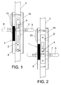
- the clutch mechanism couplable to door locks with locking bolt operated by handles or knobs which the invention proposes, is referenced in general with the number 1 and its location can be seen diagrammatically in figure 1. It is couplable to the lock 2 or 2' attached to the side of the door 3 and whose locking bolt 4 is actuated by turning the inside 5 or outside 6 handle fitted in the ends of the square-section shaft 7 when engagement of the clutch has taken place, as we will see later on.
- the clutch mechanism 1 remains hidden beneath the plate of the lock 8 which can in turn consist of a frame covered with an embellisher.
- a motor 11 As drive unit, a motor 11 has been provided which, via the corresponding transmission body (not represented), causes a worm-screw 12 to rotate.
- a reader 13 has been provided, which is powered by batteries 14 in order to permit reading of an electronic card.
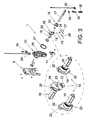
- the clutch mechanism includes the clutch elements 15 and 16, the element 15 being the one which we will call the first clutch element and is connected to the outside handle 6, while the other clutch element, or second element 16, is connected to the inside handle 5 and is integral with the square-section shaft 17 (see figure 3) and is the one that acts on the locking bolt 4.
- This second clutch element 16 constitutes in itself the element that is connected to the locking bolt of the lock and which, when turning, whether due to the actual inside handle 5 or due to the mediation of the clutch element 16 via the outside handle 6 when these elements are interconnected, as we will see later on, permits said locking bolt to be displaced to its opening position.
- the first clutch element 15 offers a square-section spike 18 for connection with the outside handle 6, this spike 18 ending in the head or disc 19 in which, perpendicular to the plane of said disc 19 and via its periphery, provision has been made for a tab 20 which enables the end of the spring 21 to be supported, the other end of which is supported on a projection of the interior body 10, as is habitual, so that it can recover its initial rest position.
- the rotary displacement of the first clutch element 15 is done against the action of said spring 21.
- head or disc 19 is a prismatic projection 22 arranged to be diametrically opposite to the tab 20, in which an orifice 23 is made in which is fitted the pulling pin 24 which is constantly pushed towards the outside of the radial orifice 23 (see figure 3) and in the direction away from the axis of rotation of the second clutch element 16 by the action of the coaxial spring 25 which assists it.
- the length of this pulling pin 24 is such that its end that is radially furthest away, when it projects due to the action of its spring 25 through the lower part of the prismatic projection 22, is at all times in contact with the arched support guide 26 of the interior body 10 (best seen in figure 3).
- the end of the pulling pin 24 is simultaneously in contact with the edge of the thruster rocker arm 27 which rotates in an oscillating fashion around the axis 28 and is assisted by the spring 29 rolled around the pivot which defines the axis 28 of oscillation of the thruster rocker arm 27 and in such a way that one of its ends (referenced with 30) intercepts the worm-screw 12 driven by the motor 11.
- the other end 31 of the spring 29 rests on the lower part of the thruster rocker arm 27.
- the displacement of the end 30 by the worm-screw 12 permits the spring 29 to flex in such a way that it pushes on the rocker arm 27 so that it can push on the pulling pin 24 which partially enters into the slot 32 (see figure 8) of the second clutch element 16 against its spring 25.
- the action of the spring 29 is greater than that of the spring 25.
- the actuation operations on the handles are compact and stable operations without any variations in the resistance to overcome and without any weakened position, via a rigid and continuous guide, and not, as in the case with European patent EP0848779 mentioned earlier, a gap between the arched projection and the coupling arm and not, as in the case of patent US 6286347 , a large moving element which can have problems for being displaced correctly due to the transverse force components originated when the pulling pin 24 is close to the ends.
- the clutch element 16, as well as the slot 32, is connected via a cam 34 with a micro-switch 34' (see figure 3) which is in turn connected to a control system in such a way that, via it, the rotation of the handle can be detected and can be processed by computer.
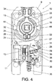
- Figure 4 shows the closed position, when the two locking handles are inoperable and the motor 3 is not in operation.
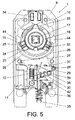
- FIG. 5 Represented in figure 5 is the closed position in which the motor 11 is not activated and in which rotation of the outside handle 6 is produced in order to open the door, which opening cannot be done because the clutch elements 15 and 16 are not connected by the pin 24 and therefore the second clutch element 16 is not displaced in order to pull on the locking bolt 4 for the lock 2. It can be seen that the pulling pin 24 is in position and can slide with its rounded end supported on the arched guide 26.
- FIG 6 Represented in figure 6 is the rest position but in which the motor 11 has already been activated via the access control system, such as for example via the reader 13 (see figures 1 and 2) and the corresponding access card.
- the motor 11 and the worm-screw 12 the spring 29 is pushed so that the thruster rocker arm 27 can rotate and in turn push on the pulling pin 24 against its spring in order to be partially introduced inside the slot 32.
- the turning of the outside handle 6 due to the two clutch elements 15 and 16 being connected, causes the second clutch element 16 to be pulled on, producing the subsequent displacement of the locking bolt to its open position.
- FIG 8 Represented in figure 8 is the open position because the motor 11 has been actuated as in the cases of figures 6 and 7 but here displacement has taken place of the locking bolt via the inside handle 5 and subsequently rotation of the second clutch element 16.
- the rotary displacement of the thruster rocker arm 27 does not produce displacement of the pulling pin 24 because the end of the latter is flush against the cylindrical periphery of the second clutch element 16 due to the slot 32 having been displaced.
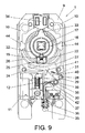
- figure 9 represented in it is the emergency system whose actuation causes engagement of the clutch in the event that the access control mechanism fails to work. It consists of an emergency push-rod 35 whose displacement against the spring 36 is carried out by certain means that are not represented and actuated by en emergency key which is also not represented.
- the end of the push-rod 35 has a special configuration by way of a lateral extension or nose in which a small depression 37 has been provided for supporting the bend end of a flexing spring 38 wound in a spiral and mounted on the stud 39 also emerging from the interior body 10, its end 40 being extended in order to form a support in the projection 41 of the rocker arm 27.
- the displacement of the thruster rocker arm 27 causes the spring 38 to flex so that its end 40 exerts pressure on the rocker arm 27 and the latter on the pulling pin 24, forcing it to enter the slot 32 of the second clutch element, thereby achieving that both clutch elements 15 and 16 remain integral in their rotation and so displacement of the locking bolt 4 is permitted.
- micro-switch 42 on which the end nose of the push-rod 35 is constantly supported, in such a way that when the latter is actuated upon in an emergency operation, the micro-switch 42 opens and its signal is sent to the computing system which memorises this operation in order to check whether an emergency actuation has been effected and when said operation was effected.
- an adjusting nut which threads on the cylindrical part of the first clutch element 15 in order to prevent any play in the rotating shaft of the outside handle.
- the rotating stop of the outside handle 6 is performed by the actual prismatic projection 22 of the first clutch element 15, in such a way that when it rotates it acts as a stop against the projections 44 provided on one and the other side in the interior body 10.
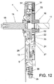
- Figure 12 shows a longitudinal cross-section of the clutch mechanism 1 and it can be seen how the pulling pin 24 guided in the prismatic projection 22 is supported on the arched guide 26 and in the thruster rocker arm 27, in such a way that the latter, when displaced upwards, can easily cause the said pulling pin 24 to be housed in the slot 32 of the second clutch element 16.
- the control for the motor can be carried out by other means, such as for example a numeric or alphabetic key-pad or any other electronic control device. Equally, the control can be done by means of a mechanical mechanism.
Abstract
Description
- As stated in the title of this descriptive specification, the present invention refers to a clutch mechanism couplable to door locks with locking bolt operated by handles or knobs, which incorporates notable advantages compared to mechanisms currently existing and having the same end, and is above all conceived with the aim of having certain narrow dimensions in order to prevent it from projecting too much with respect to the doors in which it is fitted, and that it should include a minimum number of pieces and be able to be used both in a normal position and reversed so that it can be adapted to any kind of door, with the consequent advantages of assembly leading to economic advantages.
- All the component elements are interconnected together in such a way that there is no weakening and the mechanism is very compact.
- There are basically two inventions making up the prior art: invention patent
EP 0848779 and invention patentUS 6286347 . - The first of them describes a clutch mechanism for the interconnection for locking, blocking and unblocking of the lock, which can be displaced by the inside handle and also by means of the outside handle via an actuator.
- A motor is provided which, by means of a spring shaft, connects with a screw which permits displacement of a drive lever, which acts on a thrust arm or injector with a spring with pushes said arm outwards. This arm is in turn in contact with another coupling arm capable of being introduced against the action of a spring, into a slot of a rotating drive disc connected to the arm of the lock. An arched projection has likewise been provided in order to allow the coupling arm to rotate outside of the line of the arm of the injector, there existing a gap in said arched projection in order to allow the alignment and engagement between said arms.
- Moreover, invention patent
US6286347 describes a variant of the above patent in that the arm is connected to an arched transverse member where it supports the coupling arm. In this case, the way in which the coupling arm is pushed in order to be introduced into the slot of the drive disc is via this transverse guide member. - The number of pieces required in the solutions raises problems of dimensioning, and the result is a unit of considerable thickness which projects too much when it is fitted to doors.
- Equally, the actual functional requirements of the different pieces means that its application is very limited.
- When the lock is operated, the play between the spring of the drive lever and those for the thrust arm and the coupling arm, along with the alignment of these in the gap in the guide member, also raise problems in the stabilisation and compacting of the lock, which shows positions that are certainly weakened when the outside handle is displaced.
- In general terms, the clutch mechanism couplable to door locks with locking bolt operated by handles or knobs, forming the object of the present invention, is enclosed within a casing which will be superimposed on the outside of the door and coupled to the square-section shaft of the actuation system for the locking bolt. By means of this clutch mechanism, a pulling movement is or is not transmitted to the bolt from the outside.
- Engagement of the clutch is preferably carried out with the actuation of a small motor inside the casing which produces the rotation of a worm-screw which in turn controls the displacement of a radial pin which, when actuated, performs the clutch operation. When the mechanism is at rest the pin is retracted and the rotation of the handle or knob on the outside does not entail pulling of the lever which causes the displacement of the locking bolt.
- Instead of being a motor, the drive unit can be replaced with another means, such as for example a numeric or alphanumeric key-pad or any other electronic control device, or even by means of a mechanical mechanism.
- The clutch mechanism itself consists of two pieces rotating with respect to each other and coaxial, one of which is integral with the square-section shaft which has access to the outside of the door. The other clutch element is aligned with it and has a housing for inserting of the square-section shaft as an extension, which traverses the tumbler of the lock embedded in the door and reaches as far as the inside where it is connected to the inside handle or knob.
- When the outside handle is turned, no movement is obtained in the locking bolt if this second element, connected to the inside handle, is not connected to the clutch. When both elements are interconnected then the locking bolt is allowed to be displaced to its opening position.
- The element making up the clutch is defined by a pin which occupies a radial position in one of the clutch elements, which is able to be introduced into a notch or slot provided in the other clutch element so that they both become integral with each other when they rotate.
- The pin has an end that is radially further away and is not the operational end as far as the receiver notch is concerned, and it is assisted by a spring which keeps it retracted in such a way that its exit is prevented when support is established with an arched guide concentric with the axis of rotation of the handles or knobs, provided in the interior body. This same end of the pulling pin is also in contact with a thruster rocker arm which is forced to rotate when the worm-screw of the drive unit does so, with the mediation of a spiral spring with its ends extended in separate arms, one of which rests between two contiguous spirals of the worm-screw while the other is retained in a projection of the rocker arm. When the arm connected to the worm-screw approaches at an angle with respect to the arm attached to the thruster rocker arm, the latter is displaced at an angle pushing the pin and forcing it to become introduced into the notch of the second element of the clutch mechanism. Under these conditions, when the outside handle is turned, retraction of the locking bolt does indeed take place as the two square-section shafts linked to the respective elements of the clutch system become integral with each other.
- At the moment in which the outside handle ceases to be turned and it returns to its rest position, the pin exits from the slot due to the action of the coaxial spring which assists it, since the thruster rocker arm will already have receded to its original housing position with respect to the said pin.
- As we will see later on in relation to the figures, provision has also been made so that in the event that the access control mechanism fails to work, the thruster rocker arm would not move in an angle in order to push the pin and produce engagement of the clutch. In this case there exists an emergency system which is activated by means of an emergency key the cam of which axially drives a sliding lever which acts on the arm of a second spring similar to the previous one and whose other end pushes the rocker arm so that it is displaced at an angle in the same way as was done by means of the worm-screw.
- In order to facilitate an understanding of the characteristics of the invention and forming an integral part of this descriptive specification, some drawings are attached in which figures, on an illustrative rather than limiting basis, the following has been represented:
-
- Figure 1.- Is a partial view in profile of a door fitted with a lock provided with the clutch mechanism object of the invention.
- Figure 2.- Is a view similar to figure 1 with the clutch mechanism applied to a different lock.
- Figure 3.- Is a perspective exploded view of the components of the clutch mechanism object of the invention.
- Figure 4.- Is a plant view of the same clutch mechanism as in figure 3, with all components assembled, with the exception of the cover enclosing the casing and in a door closed position and without actuating the motor.
- Figure 5.- Is a similar view to figure 4, when the outside handle has been turned and the door cannot be opened, or the bolt cannot be retracted.
- Figure 6.- Is a similar view to figures 4 and 5, with the clutch mechanism in the rest position but with the motor actuated producing engagement of the clutch which will permit the door to be opened when the outside handle is turned.
- Figure 7.- Is a similar view to figure 6, under the same conditions as the latter but with the outside handle having been turned.
- Figure 8.- Is a similar view to figure 4, once the inside handle has been turned.
- Figure 9.- Is a similar view to figure 4, once the emergency opening has been actuated so that the clutch can be operated in order to permit opening when the outside handle is turned.
- Figure 10.- Is a perspective view of the same clutch mechanism in the rest position as shown in figure 4.
- Figure 11.- Is a perspective view similar to that of figure 10, from the opposite side.
- Figure 12.- Is a transverse cross-section in longitudinal elevation of the same clutch mechanism, in the rest position.
- Figure 13.- Is an enlarged detail of the actual clutch mechanism, in the declutched position or position of retraction of the pin with respect to the receiver notch.
- Making reference to the numbering adopted in the figures, the clutch mechanism couplable to door locks with locking bolt operated by handles or knobs, which the invention proposes, is referenced in general with the
number 1 and its location can be seen diagrammatically in figure 1. It is couplable to thelock 2 or 2' attached to the side of thedoor 3 and whoselocking bolt 4 is actuated by turning theinside 5 or outside 6 handle fitted in the ends of the square-section shaft 7 when engagement of the clutch has taken place, as we will see later on. Theclutch mechanism 1 remains hidden beneath the plate of thelock 8 which can in turn consist of a frame covered with an embellisher. - It contains an
interior body 10 which houses virtually all the mechanisms and aprotective cover 9 integral with the above and which provides anti-drill protection. - As drive unit, a
motor 11 has been provided which, via the corresponding transmission body (not represented), causes a worm-screw 12 to rotate. - In figures 1 and 2 it can be seen that a
reader 13 has been provided, which is powered bybatteries 14 in order to permit reading of an electronic card. - The clutch mechanism includes the
clutch elements element 15 being the one which we will call the first clutch element and is connected to theoutside handle 6, while the other clutch element, orsecond element 16, is connected to theinside handle 5 and is integral with the square-section shaft 17 (see figure 3) and is the one that acts on thelocking bolt 4. Thissecond clutch element 16 constitutes in itself the element that is connected to the locking bolt of the lock and which, when turning, whether due to theactual inside handle 5 or due to the mediation of theclutch element 16 via theoutside handle 6 when these elements are interconnected, as we will see later on, permits said locking bolt to be displaced to its opening position. - The
first clutch element 15 offers a square-section spike 18 for connection with theoutside handle 6, thisspike 18 ending in the head ordisc 19 in which, perpendicular to the plane of saiddisc 19 and via its periphery, provision has been made for atab 20 which enables the end of thespring 21 to be supported, the other end of which is supported on a projection of theinterior body 10, as is habitual, so that it can recover its initial rest position. The rotary displacement of thefirst clutch element 15 is done against the action of saidspring 21. - Also provided in that head or
disc 19 is aprismatic projection 22 arranged to be diametrically opposite to thetab 20, in which anorifice 23 is made in which is fitted the pullingpin 24 which is constantly pushed towards the outside of the radial orifice 23 (see figure 3) and in the direction away from the axis of rotation of thesecond clutch element 16 by the action of thecoaxial spring 25 which assists it. The length of this pullingpin 24 is such that its end that is radially furthest away, when it projects due to the action of itsspring 25 through the lower part of theprismatic projection 22, is at all times in contact with thearched support guide 26 of the interior body 10 (best seen in figure 3). - In turn, the end of the pulling
pin 24 is simultaneously in contact with the edge of thethruster rocker arm 27 which rotates in an oscillating fashion around theaxis 28 and is assisted by thespring 29 rolled around the pivot which defines theaxis 28 of oscillation of thethruster rocker arm 27 and in such a way that one of its ends (referenced with 30) intercepts the worm-screw 12 driven by themotor 11. Theother end 31 of thespring 29 rests on the lower part of thethruster rocker arm 27. The displacement of theend 30 by the worm-screw 12 permits thespring 29 to flex in such a way that it pushes on therocker arm 27 so that it can push on the pullingpin 24 which partially enters into the slot 32 (see figure 8) of thesecond clutch element 16 against itsspring 25. The action of thespring 29 is greater than that of thespring 25. - Therefore, once the pulling
pin 24 is introduced into theslot 32, the first and second elements of the clutch become connected in such a way that when one of them turns the other does so too and with that thebolt 4 for thelock 2 or 2' is displaced. - In the displacement from the open position at rest to open turned, the opening tension, which is created against the action of the
spring 21 and of the tumbler spring of the lock 2-2' and the actual friction of the pullingpin 24 against the walls of theslot 32, is sufficient so that saidpin 24 is not displaced outwards by the action of its spring. - At the moment that the
outside handle 6 ceases to be acted upon and it returns to its horizontal position, thespring 25 pushes thepin 24 so that it exits from theslot 32. - One of the important characteristics of the structure lies in the position of the
arched guide 26 which is concentric with the axis of rotation of theclutch elements pin 24 is outside of theslot 32, it has its end at all times in contact with thearched guide 26. Therefore, the actuation operations on the handles are compact and stable operations without any variations in the resistance to overcome and without any weakened position, via a rigid and continuous guide, and not, as in the case withEuropean patent EP0848779 mentioned earlier, a gap between the arched projection and the coupling arm and not, as in the case of patentUS 6286347 , a large moving element which can have problems for being displaced correctly due to the transverse force components originated when the pullingpin 24 is close to the ends. Theclutch element 16, as well as theslot 32, is connected via acam 34 with a micro-switch 34' (see figure 3) which is in turn connected to a control system in such a way that, via it, the rotation of the handle can be detected and can be processed by computer. - Figure 4 shows the closed position, when the two locking handles are inoperable and the
motor 3 is not in operation. - Represented in figure 5 is the closed position in which the
motor 11 is not activated and in which rotation of theoutside handle 6 is produced in order to open the door, which opening cannot be done because theclutch elements pin 24 and therefore the secondclutch element 16 is not displaced in order to pull on thelocking bolt 4 for thelock 2. It can be seen that the pullingpin 24 is in position and can slide with its rounded end supported on thearched guide 26. - Represented in figure 6 is the rest position but in which the
motor 11 has already been activated via the access control system, such as for example via the reader 13 (see figures 1 and 2) and the corresponding access card. In this case, by means of themotor 11 and the worm-screw 12, thespring 29 is pushed so that thethruster rocker arm 27 can rotate and in turn push on the pullingpin 24 against its spring in order to be partially introduced inside theslot 32. In this case, and going on now to figure 7, the turning of theoutside handle 6, due to the twoclutch elements clutch element 16 to be pulled on, producing the subsequent displacement of the locking bolt to its open position. - Represented in figure 8 is the open position because the
motor 11 has been actuated as in the cases of figures 6 and 7 but here displacement has taken place of the locking bolt via theinside handle 5 and subsequently rotation of the secondclutch element 16. The rotary displacement of thethruster rocker arm 27 does not produce displacement of the pullingpin 24 because the end of the latter is flush against the cylindrical periphery of the secondclutch element 16 due to theslot 32 having been displaced. Let us remember that in this position of figure 8, theinside handle 5 has been actuated. - Making special mention now of figure 9, represented in it is the emergency system whose actuation causes engagement of the clutch in the event that the access control mechanism fails to work. It consists of an emergency push-
rod 35 whose displacement against thespring 36 is carried out by certain means that are not represented and actuated by en emergency key which is also not represented. - The end of the push-
rod 35 has a special configuration by way of a lateral extension or nose in which asmall depression 37 has been provided for supporting the bend end of a flexingspring 38 wound in a spiral and mounted on thestud 39 also emerging from theinterior body 10, itsend 40 being extended in order to form a support in theprojection 41 of therocker arm 27. The displacement of thethruster rocker arm 27 causes thespring 38 to flex so that itsend 40 exerts pressure on therocker arm 27 and the latter on the pullingpin 24, forcing it to enter theslot 32 of the second clutch element, thereby achieving that bothclutch elements locking bolt 4 is permitted. - Provision has been made for a micro-switch 42 on which the end nose of the push-
rod 35 is constantly supported, in such a way that when the latter is actuated upon in an emergency operation, themicro-switch 42 opens and its signal is sent to the computing system which memorises this operation in order to check whether an emergency actuation has been effected and when said operation was effected. - In figures 10 and 11 the entire
clutch mechanism 1 is shown and on its front face can be seen theprotective cover 9 andprotective plate 43 in order to prevent vandals from drilling intoclutch element 15. - Also to be seen is an adjusting nut which threads on the cylindrical part of the first
clutch element 15 in order to prevent any play in the rotating shaft of the outside handle. - With this arrangement presented by the clutch mechanism of the invention, various applications are permitted such as those shown in figures 1 and 2 in which the mechanism can be fitted in one position or its reverse without the different components having any functional problems on account of occupying these different positions.
- The rotating stop of the
outside handle 6 is performed by the actualprismatic projection 22 of the firstclutch element 15, in such a way that when it rotates it acts as a stop against theprojections 44 provided on one and the other side in theinterior body 10. - Figure 12 shows a longitudinal cross-section of the
clutch mechanism 1 and it can be seen how the pullingpin 24 guided in theprismatic projection 22 is supported on thearched guide 26 and in thethruster rocker arm 27, in such a way that the latter, when displaced upwards, can easily cause the said pullingpin 24 to be housed in theslot 32 of the secondclutch element 16. - The control for the motor can be carried out by other means, such as for example a numeric or alphabetic key-pad or any other electronic control device. Equally, the control can be done by means of a mechanical mechanism.
Claims (5)
- CLUTCH MECHANISM COUPLABLE TO DOOR LOCKS WITH LOCKING BOLT OPERATED BY HANDLES OR KNOBS, with which a pulling movement manages to be transferred or not to the bolt for the lock and of the type of those that are mounted in a casing superimposed on the door and whose square-section shaft operated by the handles is formed from two aligned elements able to become locked in rotation, characterised in that it comprises a protector cover (9) integral with an interior body (10) which houses the actuation mechanisms where a motor (11) is to be found for driving a worm-screw (12), there existing a first clutch element (15) and a second clutch element (16) respectively connected to the outside (6) and inside (5) handle, the second clutch element (16) acting on the locking bolt (4) of the lock, the first clutch element (15) offering a square-section spike (18) connected to the outside handle (6) and a head or disc (19) fitted with an eccentric and axial tab (20) which turns on the spike part (18) and on which there rests one end of the spring (21) for recovery of the handles (5, 6), the other end being fixed to a projection of the interior body (10), said head or disc (19) having diametrically opposite to the tab (20) a prismatic extension (22) with an orifice (23) in which fits a pulling pin (24), radial to that head or disc (19) and pushed radially outwards by a spring (25) in such a way that it is at all times in contact with an arched guide (26) of the interior body (10) and also with the edge of a thruster rocker arm (27) oscillating at a point (28) of the interior body (10) and assisted by a spring (29) which pushes it against the pulling pin (24) when the worm-screw (12) turns in order to cause engagement of the clutch when said pulling pin (24) is introduced into a slot (32) of the second clutch element (16).
- CLUTCH MECHANISM COUPLABLE TO DOOR LOCKS WITH LOCKING BOLT OPERATED BY HANDLES OR KNOBS, according to claim 1, characterised in that the spring (29) which acts on the thruster rocker arm (27) has one end (31) supported on an internal projection of the thruster rocker arm (27) and the other does so between the spirals of the actual worm-screw (12), being able to exert pressure due to the rotation of the motor (11) until it displaces the pulling pin (24) against its spring (25) so that it enters said slot (32) of the second clutch element (16).
- CLUTCH MECHANISM COUPLABLE TO DOOR LOCKS WITH LOCKING BOLT OPERATED BY HANDLES OR KNOBS, according to the above claims, characterised in that the second clutch element (16) includes diametrically opposite to its slot (32) a radial projection (33) able to make contact with a micro-switch (34) housed in the interior body (10) and which forms part of a computer control system for controlling the number of times the lock is operated on and when.
- CLUTCH MECHANISM COUPLABLE TO DOOR LOCKS WITH LOCKING BOLT OPERATED BY HANDLES OR KNOBS, according to claim 1, characterised in that it includes an emergency opening system comprising a rod (35) guided in the interior body (10) and assisted by a spring (36) which keeps it in the retracted position and ready so that its outer end can be operated by an emergency key which displaces it linearly pushing directly on a radial end of a spring (38) whose other end (40) is supported on a projection (41) of the thuster rocker arm (27) forcing it to rotate and displace the pulling pin (24) and engaging the clutch.
- CLUTCH MECHANISM COUPLABLE TO DOOR LOCKS WITH LOCKING BOLT OPERATED BY HANDLES OR KNOBS, according to claim 4, characterised in that the rod (35) has a lateral extension which constantly presses on a micro-switch (42) which opens when actuated with the emergency key and sends a signal to the computing system which memorises this operation and when it was effected.
Applications Claiming Priority (1)
| Application Number | Priority Date | Filing Date | Title |
|---|---|---|---|
| ES200601707A ES2323201B1 (en) | 2006-06-26 | 2006-06-26 | CLUTCH MECHANISM COUPLABLE TO DOOR LOCKS WITH CLOSURE LATCH OPERATED BY HANDLES OR KNOBS. |
Publications (2)
| Publication Number | Publication Date |
|---|---|
| EP1881135A1 true EP1881135A1 (en) | 2008-01-23 |
| EP1881135B1 EP1881135B1 (en) | 2018-01-17 |
Family
ID=38752387
Family Applications (1)
| Application Number | Title | Priority Date | Filing Date |
|---|---|---|---|
| EP07380184.7A Active EP1881135B1 (en) | 2006-06-26 | 2007-06-26 | Clutch mechanism couplable to door locks with locking bolt operated by handles or knobs |
Country Status (4)
| Country | Link |
|---|---|
| US (1) | US8001818B2 (en) |
| EP (1) | EP1881135B1 (en) |
| DK (1) | DK1881135T3 (en) |
| ES (2) | ES2323201B1 (en) |
Cited By (14)
| Publication number | Priority date | Publication date | Assignee | Title |
|---|---|---|---|---|
| WO2010000332A1 (en) * | 2008-07-04 | 2010-01-07 | Inventio Ag | Method for operation of an elevator system, and method for operation of a building door |
| WO2010130850A1 (en) * | 2009-05-13 | 2010-11-18 | Talleres De Escoriaza, S.A. | Clutch device for electric mortise locks with anti-panic function |
| WO2012015135A1 (en) * | 2010-07-30 | 2012-02-02 | 주식회사 아이레보 | Electronic door lock device for connecting clutch easily |
| WO2012109713A1 (en) | 2011-02-15 | 2012-08-23 | Mauer Locking Systems Ltd | Clutch mechanism couplable to door locks with locking bolt operated by handles or knobs |
| CN102995978A (en) * | 2012-12-10 | 2013-03-27 | 深圳市威捷机电技术有限公司 | Mechanical/electric ground latch |
| CN104358472A (en) * | 2014-10-29 | 2015-02-18 | 陈荣龙 | Clutch of handle lock |
| DE102014103666A1 (en) | 2014-03-18 | 2015-09-24 | Günter Uhlmann | door handles |
| CN105113855A (en) * | 2015-09-21 | 2015-12-02 | 肖钧 | Engaging and disengaging mechanism of electronic core insertion lock |
| DE102015112859B3 (en) * | 2015-08-05 | 2016-11-03 | Uhlmann & Zacher Gmbh | Door handle and drive carrier |
| CN107386797A (en) * | 2017-08-13 | 2017-11-24 | 宁波鄞州竹创信息科技有限公司 | A kind of lock assembly based on clutch |
| EP3284886A1 (en) * | 2016-08-17 | 2018-02-21 | BKS GmbH | Closing device for a door |
| DE202019101391U1 (en) * | 2018-11-29 | 2020-03-03 | Gebr. Bode Gmbh & Co. Kg | Device for locking an electrical outer or inner swing door |
| EP3699377A1 (en) | 2019-02-22 | 2020-08-26 | Aug. Winkhaus GmbH & Co. KG | Coupling mechanism for mechatronic locking system |
| WO2023076962A1 (en) * | 2021-10-26 | 2023-05-04 | Spectrum Brands, Inc. | Drive mechanism for electronic deadbolt |
Families Citing this family (36)
| Publication number | Priority date | Publication date | Assignee | Title |
|---|---|---|---|---|
| DE10320873B4 (en) * | 2003-05-09 | 2006-02-09 | Simonsvoss Technologies Ag | Motion transmission device and method |
| US8011217B2 (en) * | 2003-05-09 | 2011-09-06 | Simonsvoss Technologies Ag | Electronic access control handle set for a door lock |
| US7845201B2 (en) * | 2003-05-09 | 2010-12-07 | Simonsvoss Technologies Ag | Electronic access control device |
| US8683833B2 (en) * | 2003-05-09 | 2014-04-01 | Simonsvoss Technologies Ag | Electronic access control handle set for a door lock |
| US20040255628A1 (en) * | 2003-05-09 | 2004-12-23 | Herbert Meyerle | Door lock system and method |
| US8931315B2 (en) * | 2006-04-13 | 2015-01-13 | Schlage Lock Company | Electronic deadbolt lock |
| US7908896B1 (en) * | 2006-10-23 | 2011-03-22 | Olson Timothy L | Biometric deadbolt lock assembly |
| WO2010062282A1 (en) * | 2008-11-28 | 2010-06-03 | Utc Fire & Security Corporation | Semi-active electrorheological fluid clutch for electronic door lock |
| FI20095694A (en) * | 2009-01-05 | 2010-07-06 | Megalock Oy | Wireless controllable electric lock |
| DE102009006352B4 (en) * | 2009-01-28 | 2011-02-17 | G. Schwepper Beschlag Gmbh + Co | Lock box |
| US8079238B2 (en) * | 2010-02-23 | 2011-12-20 | Thase Enterprise Co., Ltd. | Lock device |
| ES1073095Y (en) | 2010-05-04 | 2011-02-07 | Sist S Valle Leniz S L U | ELECTROMECHANICAL LOCK ADAPTED TO DOORS |
| US8590948B2 (en) * | 2011-01-12 | 2013-11-26 | I-Tek Metal Mfg. Co., Ltd | Outer operational device for panic exit door lock |
| AU2013215310B2 (en) | 2012-01-30 | 2016-09-08 | Schlage Lock Company Llc | Lock devices, systems and methods |
| US20140021002A1 (en) * | 2012-07-18 | 2014-01-23 | Scyan Electronics LLC | Lock clutches and methods of making and using thereof |
| US20140238979A1 (en) * | 2013-02-27 | 2014-08-28 | Jen Mei Tai | Modular Shipping Container |
| CN103233611B (en) * | 2013-04-23 | 2015-09-16 | 浙江亚合大机电科技有限公司 | A kind of door lock clutch device |
| CN103835575B (en) * | 2014-03-19 | 2016-04-20 | 曹国基 | There is the anti-lockset knocking unlatching clutch |
| CN104372996B (en) * | 2014-11-14 | 2017-04-26 | 宁波瑞奥物联技术股份有限公司 | Safe and reliable electronic lock |
| CN104929440B (en) * | 2015-06-26 | 2018-05-04 | 黄大任 | One kind is without key intelligent theftproof lock |
| CN104948024B (en) * | 2015-07-24 | 2017-06-16 | 黄大任 | A kind of intelligent anti-lock device |
| CN105239827A (en) * | 2015-11-11 | 2016-01-13 | 西安慧晶智能科技有限公司 | Front handle structure of fingerprint password anti-theft lock |
| US11377875B2 (en) | 2016-09-19 | 2022-07-05 | Level Home, Inc. | Deadbolt position sensing |
| ES2684529B1 (en) * | 2017-03-30 | 2019-07-09 | Talleres Escoriaza Sa | Automatic and panic lock perfected |
| CN107044226B (en) * | 2017-05-27 | 2022-10-14 | 深圳市万厦福智能锁业有限公司 | Electronic lock with standby unlocking device |
| CA3076893C (en) * | 2017-08-08 | 2023-03-14 | Schlage Lock Company Llc | Door hardware noise reduction and evaluation |
| US10890019B2 (en) * | 2017-10-24 | 2021-01-12 | Wfe Technology Corp. | Reversible electric door lock |
| US11187008B2 (en) * | 2018-04-18 | 2021-11-30 | Assa Abloy Korea | Clutch engagement assembly of door lock and driving device thereof |
| CN108487789A (en) * | 2018-05-08 | 2018-09-04 | 陈坤 | Lock body with clutch |
| US11377872B2 (en) * | 2018-06-07 | 2022-07-05 | Schlage Lock Company Llc | Cylindrical lock with a clutching and a non-clutching configuration |
| CA3111566A1 (en) * | 2018-09-10 | 2020-03-19 | Spectrum Brands, Inc. | Locking assembly with spring mechanism |
| US11639617B1 (en) | 2019-04-03 | 2023-05-02 | The Chamberlain Group Llc | Access control system and method |
| US11851915B2 (en) * | 2020-04-28 | 2023-12-26 | Schlage Lock Company Llc | Rotation converter |
| SE545946C2 (en) * | 2020-06-12 | 2024-03-19 | Stendals El Ab | Adapter for a locking device for unlocking by an inner handle in an emergency function |
| CN113833365B (en) * | 2021-09-23 | 2024-01-26 | 江苏安威士智能安防有限公司 | Electromechanical intelligent door handle |
| TWI810821B (en) * | 2022-02-18 | 2023-08-01 | 一德金屬工業股份有限公司 | lock with clutch |
Citations (8)
| Publication number | Priority date | Publication date | Assignee | Title |
|---|---|---|---|---|
| WO1997009501A1 (en) * | 1995-09-06 | 1997-03-13 | Harrow Products, Inc. | Clutch mechanism for door lock system |
| US6286347B1 (en) * | 1999-08-09 | 2001-09-11 | Harrow Products, Inc. | Clutch mechanism with moveable injector retainer wall for door lock system |
| EP1154105A2 (en) * | 2000-05-08 | 2001-11-14 | Harrow Products Inc. | Modular electronic door security system |
| EP1174570A1 (en) * | 2000-07-21 | 2002-01-23 | Harrow Products Inc. | Mortise lockset with internal clutch |
| US6640594B1 (en) * | 2002-07-03 | 2003-11-04 | Shyang Feng Electric & Machinery Co., Ltd. | Electronic lock |
| EP1522659A2 (en) * | 2003-10-10 | 2005-04-13 | CISA S.p.A. | Electric lock with multiple-function spring |
| WO2005124069A1 (en) * | 2004-06-22 | 2005-12-29 | Assa Ab | A device for mechanical guiding, a lock module and a lock device comprising such a device |
| EP1624141A1 (en) * | 2004-08-02 | 2006-02-08 | Talleres De Escoriaza, S.A. | Clutch mechanism for locks |
Family Cites Families (8)
| Publication number | Priority date | Publication date | Assignee | Title |
|---|---|---|---|---|
| US5475996A (en) * | 1994-08-29 | 1995-12-19 | Chen; Tsun-Hsing | Electromagnetic door lock |
| ES2138523B1 (en) * | 1997-02-27 | 2000-05-16 | Talleres Escoriaza Sa | SECURITY CLOSURE FOR ACCESS CONTROL. |
| ES2189571B2 (en) * | 1999-12-31 | 2004-06-01 | Escudos Kala Internacional, S.L. | CLUTCH MECHANISM FOR ELECTRONIC LOCKS. |
| ES2193793B2 (en) * | 2000-03-01 | 2005-02-01 | Escudos Kala Internacional, S.L. | CONDEMNATION MECHANISM FOR ELECTRONIC LOCKS. |
| ES2191522B1 (en) * | 2000-12-11 | 2004-11-01 | Talleres De Escoriaza, S.A. | CLUTCH DEVICE FOR LOCKER. |
| ES2213430B1 (en) * | 2001-11-08 | 2005-05-01 | Talleres De Escoriaza, S.A. | CLUTCH MECHANISM FOR LOCKS. |
| US7096698B2 (en) * | 2003-03-11 | 2006-08-29 | Harrow Products Llc | Override assembly for door lock systems having a clutch mechanism |
| US7007526B2 (en) * | 2003-09-08 | 2006-03-07 | Harrow Products, Inc. | Electronic clutch assembly for a lock system |
-
2006
- 2006-06-26 ES ES200601707A patent/ES2323201B1/en not_active Expired - Fee Related
-
2007
- 2007-06-25 US US11/819,102 patent/US8001818B2/en active Active
- 2007-06-26 DK DK07380184.7T patent/DK1881135T3/en active
- 2007-06-26 EP EP07380184.7A patent/EP1881135B1/en active Active
- 2007-06-26 ES ES07380184.7T patent/ES2663206T3/en active Active
Patent Citations (9)
| Publication number | Priority date | Publication date | Assignee | Title |
|---|---|---|---|---|
| WO1997009501A1 (en) * | 1995-09-06 | 1997-03-13 | Harrow Products, Inc. | Clutch mechanism for door lock system |
| EP0848779A1 (en) * | 1995-09-06 | 1998-06-24 | Harrow Products Inc. | Clutch mechanism for door lock system |
| US6286347B1 (en) * | 1999-08-09 | 2001-09-11 | Harrow Products, Inc. | Clutch mechanism with moveable injector retainer wall for door lock system |
| EP1154105A2 (en) * | 2000-05-08 | 2001-11-14 | Harrow Products Inc. | Modular electronic door security system |
| EP1174570A1 (en) * | 2000-07-21 | 2002-01-23 | Harrow Products Inc. | Mortise lockset with internal clutch |
| US6640594B1 (en) * | 2002-07-03 | 2003-11-04 | Shyang Feng Electric & Machinery Co., Ltd. | Electronic lock |
| EP1522659A2 (en) * | 2003-10-10 | 2005-04-13 | CISA S.p.A. | Electric lock with multiple-function spring |
| WO2005124069A1 (en) * | 2004-06-22 | 2005-12-29 | Assa Ab | A device for mechanical guiding, a lock module and a lock device comprising such a device |
| EP1624141A1 (en) * | 2004-08-02 | 2006-02-08 | Talleres De Escoriaza, S.A. | Clutch mechanism for locks |
Cited By (26)
| Publication number | Priority date | Publication date | Assignee | Title |
|---|---|---|---|---|
| WO2010000332A1 (en) * | 2008-07-04 | 2010-01-07 | Inventio Ag | Method for operation of an elevator system, and method for operation of a building door |
| WO2010130850A1 (en) * | 2009-05-13 | 2010-11-18 | Talleres De Escoriaza, S.A. | Clutch device for electric mortise locks with anti-panic function |
| ES2350218A1 (en) * | 2009-05-13 | 2011-01-20 | Talleres De Escoriaza, S.A. | Clutch device for electric mortise locks with anti-panic function |
| EP2431557A1 (en) * | 2009-05-13 | 2012-03-21 | Talleres De Escoriaza, S.A. | Clutch device for electric mortise locks with anti-panic function |
| EP2431557A4 (en) * | 2009-05-13 | 2014-12-10 | Talleres Escoriaza Sa | Clutch device for electric mortise locks with anti-panic function |
| WO2012015135A1 (en) * | 2010-07-30 | 2012-02-02 | 주식회사 아이레보 | Electronic door lock device for connecting clutch easily |
| WO2012109713A1 (en) | 2011-02-15 | 2012-08-23 | Mauer Locking Systems Ltd | Clutch mechanism couplable to door locks with locking bolt operated by handles or knobs |
| CN102995978B (en) * | 2012-12-10 | 2015-07-01 | 深圳市威捷机电股份公司 | Mechanical/electric ground latch |
| CN102995978A (en) * | 2012-12-10 | 2013-03-27 | 深圳市威捷机电技术有限公司 | Mechanical/electric ground latch |
| DE102014103666C9 (en) | 2014-03-18 | 2019-06-06 | Günter Uhlmann | door handles |
| DE102014103666C5 (en) | 2014-03-18 | 2019-03-14 | Günter Uhlmann | door handles |
| DE102014103666B4 (en) * | 2014-03-18 | 2015-11-12 | Günter Uhlmann | door handles |
| US10422162B2 (en) | 2014-03-18 | 2019-09-24 | Günter Uhlmann | Door handle |
| DE102014103666A1 (en) | 2014-03-18 | 2015-09-24 | Günter Uhlmann | door handles |
| CN104358472A (en) * | 2014-10-29 | 2015-02-18 | 陈荣龙 | Clutch of handle lock |
| CN104358472B (en) * | 2014-10-29 | 2017-03-22 | 中山市逸家安防科技有限公司 | Clutch of handle lock |
| DE102015112859B3 (en) * | 2015-08-05 | 2016-11-03 | Uhlmann & Zacher Gmbh | Door handle and drive carrier |
| US10927569B2 (en) | 2015-08-05 | 2021-02-23 | Uhlmann & Zacher Gmbh | Door handle and drive support for an electromagnetic door lock |
| CN105113855A (en) * | 2015-09-21 | 2015-12-02 | 肖钧 | Engaging and disengaging mechanism of electronic core insertion lock |
| EP3284886A1 (en) * | 2016-08-17 | 2018-02-21 | BKS GmbH | Closing device for a door |
| CN107386797A (en) * | 2017-08-13 | 2017-11-24 | 宁波鄞州竹创信息科技有限公司 | A kind of lock assembly based on clutch |
| CN107386797B (en) * | 2017-08-13 | 2019-10-08 | 浙江品瑶科技股份有限公司 | A kind of lock assembly based on clutch |
| DE202019101391U1 (en) * | 2018-11-29 | 2020-03-03 | Gebr. Bode Gmbh & Co. Kg | Device for locking an electrical outer or inner swing door |
| DE102019132409B4 (en) | 2018-11-29 | 2022-07-07 | Bode - Die Tür Gmbh | Device for locking an electric outward or inward swing door |
| EP3699377A1 (en) | 2019-02-22 | 2020-08-26 | Aug. Winkhaus GmbH & Co. KG | Coupling mechanism for mechatronic locking system |
| WO2023076962A1 (en) * | 2021-10-26 | 2023-05-04 | Spectrum Brands, Inc. | Drive mechanism for electronic deadbolt |
Also Published As
| Publication number | Publication date |
|---|---|
| ES2323201B1 (en) | 2010-04-20 |
| DK1881135T3 (en) | 2018-04-30 |
| US8001818B2 (en) | 2011-08-23 |
| ES2663206T3 (en) | 2018-04-11 |
| ES2323201A1 (en) | 2009-07-08 |
| EP1881135B1 (en) | 2018-01-17 |
| US20080011030A1 (en) | 2008-01-17 |
Similar Documents
| Publication | Publication Date | Title |
|---|---|---|
| EP1881135B1 (en) | Clutch mechanism couplable to door locks with locking bolt operated by handles or knobs | |
| US6427505B2 (en) | Latch mechanism for electronic locks | |
| EP2115250B1 (en) | Solenoid-operated electromechanical lock | |
| US6845642B2 (en) | Clutch mechanism for electronic locks | |
| CA3010376C (en) | A door strike having a kicker and an adjustable dead latch release | |
| KR101109804B1 (en) | Lock assembly including a rotary blocking device and tamper resistant mechanism | |
| KR101756565B1 (en) | Improved rotary blocking device | |
| EP2137366B1 (en) | Compact electric striker with a slide link | |
| US20010009105A1 (en) | Gate latch | |
| WO1998023830A1 (en) | Catch mechanism for locks | |
| US8333411B2 (en) | Lock mechanism | |
| AU2007101222B4 (en) | Improved Lock | |
| US5570916A (en) | Breakaway lever clutch with vertical lift trim | |
| US5651568A (en) | Privacy snib mechanism | |
| EP0662552A2 (en) | A door lever assembly | |
| JPH08135279A (en) | Lock handle device of door used for both right and left hands | |
| WO2011149849A1 (en) | Multiple access door lock mechanism with reversible cam actuation | |
| WO2020000040A1 (en) | Electric strike assembly | |
| US5516161A (en) | Breakaway lever clutch with cam drive pin | |
| EP3262257B1 (en) | Universal lock with sliding blocking mechanism | |
| EP2458114A2 (en) | Multi-purpose casing for reversible actuation and traditional and/or antipanic actuation in locks for joinery based on metallic profile sections | |
| CA2808699C (en) | Self-adjusting cam assembly | |
| KR200344026Y1 (en) | Forced opening and closing structure of locking in a door | |
| JP3664451B2 (en) | Electric lock | |
| AU775134B2 (en) | Gate latch |
Legal Events
| Date | Code | Title | Description |
|---|---|---|---|
| PUAI | Public reference made under article 153(3) epc to a published international application that has entered the european phase |
Free format text: ORIGINAL CODE: 0009012 |
|
| AK | Designated contracting states |
Kind code of ref document: A1 Designated state(s): AT BE BG CH CY CZ DE DK EE ES FI FR GB GR HU IE IS IT LI LT LU LV MC MT NL PL PT RO SE SI SK TR |
|
| AX | Request for extension of the european patent |
Extension state: AL BA HR MK YU |
|
| 17P | Request for examination filed |
Effective date: 20080707 |
|
| R17P | Request for examination filed (corrected) |
Effective date: 20080707 |
|
| AKX | Designation fees paid |
Designated state(s): AT BE BG CH CY CZ DE DK EE ES FI FR GB GR HU IE IS IT LI LT LU LV MC MT NL PL PT RO SE SI SK TR |
|
| 17Q | First examination report despatched |
Effective date: 20170313 |
|
| GRAP | Despatch of communication of intention to grant a patent |
Free format text: ORIGINAL CODE: EPIDOSNIGR1 |
|
| INTG | Intention to grant announced |
Effective date: 20170906 |
|
| RIN1 | Information on inventor provided before grant (corrected) |
Inventor name: IMEDIO OCANA, JUAN ANTONIO Inventor name: FERREIRA SANCHEZ, CARLOS |
|
| GRAS | Grant fee paid |
Free format text: ORIGINAL CODE: EPIDOSNIGR3 |
|
| GRAA | (expected) grant |
Free format text: ORIGINAL CODE: 0009210 |
|
| AK | Designated contracting states |
Kind code of ref document: B1 Designated state(s): AT BE BG CH CY CZ DE DK EE ES FI FR GB GR HU IE IS IT LI LT LU LV MC MT NL PL PT RO SE SI SK TR |
|
| REG | Reference to a national code |
Ref country code: GB Ref legal event code: FG4D |
|
| REG | Reference to a national code |
Ref country code: CH Ref legal event code: EP |
|
| REG | Reference to a national code |
Ref country code: IE Ref legal event code: FG4D |
|
| REG | Reference to a national code |
Ref country code: AT Ref legal event code: REF Ref document number: 964535 Country of ref document: AT Kind code of ref document: T Effective date: 20180215 |
|
| REG | Reference to a national code |
Ref country code: DE Ref legal event code: R096 Ref document number: 602007053749 Country of ref document: DE |
|
| REG | Reference to a national code |
Ref country code: ES Ref legal event code: FG2A Ref document number: 2663206 Country of ref document: ES Kind code of ref document: T3 Effective date: 20180411 |
|
| REG | Reference to a national code |
Ref country code: CH Ref legal event code: NV Representative=s name: ISLER AND PEDRAZZINI AG, CH Ref country code: DK Ref legal event code: T3 Effective date: 20180423 |
|
| REG | Reference to a national code |
Ref country code: FR Ref legal event code: PLFP Year of fee payment: 12 |
|
| REG | Reference to a national code |
Ref country code: NL Ref legal event code: MP Effective date: 20180117 |
|
| REG | Reference to a national code |
Ref country code: LT Ref legal event code: MG4D |
|
| PG25 | Lapsed in a contracting state [announced via postgrant information from national office to epo] |
Ref country code: NL Free format text: LAPSE BECAUSE OF FAILURE TO SUBMIT A TRANSLATION OF THE DESCRIPTION OR TO PAY THE FEE WITHIN THE PRESCRIBED TIME-LIMIT Effective date: 20180117 |
|
| PG25 | Lapsed in a contracting state [announced via postgrant information from national office to epo] |
Ref country code: LT Free format text: LAPSE BECAUSE OF FAILURE TO SUBMIT A TRANSLATION OF THE DESCRIPTION OR TO PAY THE FEE WITHIN THE PRESCRIBED TIME-LIMIT Effective date: 20180117 Ref country code: FI Free format text: LAPSE BECAUSE OF FAILURE TO SUBMIT A TRANSLATION OF THE DESCRIPTION OR TO PAY THE FEE WITHIN THE PRESCRIBED TIME-LIMIT Effective date: 20180117 Ref country code: CY Free format text: LAPSE BECAUSE OF FAILURE TO SUBMIT A TRANSLATION OF THE DESCRIPTION OR TO PAY THE FEE WITHIN THE PRESCRIBED TIME-LIMIT Effective date: 20180117 |
|
| PG25 | Lapsed in a contracting state [announced via postgrant information from national office to epo] |
Ref country code: PL Free format text: LAPSE BECAUSE OF FAILURE TO SUBMIT A TRANSLATION OF THE DESCRIPTION OR TO PAY THE FEE WITHIN THE PRESCRIBED TIME-LIMIT Effective date: 20180117 Ref country code: BG Free format text: LAPSE BECAUSE OF FAILURE TO SUBMIT A TRANSLATION OF THE DESCRIPTION OR TO PAY THE FEE WITHIN THE PRESCRIBED TIME-LIMIT Effective date: 20180417 Ref country code: IS Free format text: LAPSE BECAUSE OF FAILURE TO SUBMIT A TRANSLATION OF THE DESCRIPTION OR TO PAY THE FEE WITHIN THE PRESCRIBED TIME-LIMIT Effective date: 20180517 Ref country code: SE Free format text: LAPSE BECAUSE OF FAILURE TO SUBMIT A TRANSLATION OF THE DESCRIPTION OR TO PAY THE FEE WITHIN THE PRESCRIBED TIME-LIMIT Effective date: 20180117 Ref country code: LV Free format text: LAPSE BECAUSE OF FAILURE TO SUBMIT A TRANSLATION OF THE DESCRIPTION OR TO PAY THE FEE WITHIN THE PRESCRIBED TIME-LIMIT Effective date: 20180117 |
|
| REG | Reference to a national code |
Ref country code: DE Ref legal event code: R097 Ref document number: 602007053749 Country of ref document: DE |
|
| PG25 | Lapsed in a contracting state [announced via postgrant information from national office to epo] |
Ref country code: EE Free format text: LAPSE BECAUSE OF FAILURE TO SUBMIT A TRANSLATION OF THE DESCRIPTION OR TO PAY THE FEE WITHIN THE PRESCRIBED TIME-LIMIT Effective date: 20180117 Ref country code: RO Free format text: LAPSE BECAUSE OF FAILURE TO SUBMIT A TRANSLATION OF THE DESCRIPTION OR TO PAY THE FEE WITHIN THE PRESCRIBED TIME-LIMIT Effective date: 20180117 |
|
| PLBE | No opposition filed within time limit |
Free format text: ORIGINAL CODE: 0009261 |
|
| STAA | Information on the status of an ep patent application or granted ep patent |
Free format text: STATUS: NO OPPOSITION FILED WITHIN TIME LIMIT |
|
| PG25 | Lapsed in a contracting state [announced via postgrant information from national office to epo] |
Ref country code: CZ Free format text: LAPSE BECAUSE OF FAILURE TO SUBMIT A TRANSLATION OF THE DESCRIPTION OR TO PAY THE FEE WITHIN THE PRESCRIBED TIME-LIMIT Effective date: 20180117 Ref country code: SK Free format text: LAPSE BECAUSE OF FAILURE TO SUBMIT A TRANSLATION OF THE DESCRIPTION OR TO PAY THE FEE WITHIN THE PRESCRIBED TIME-LIMIT Effective date: 20180117 |
|
| 26N | No opposition filed |
Effective date: 20181018 |
|
| PG25 | Lapsed in a contracting state [announced via postgrant information from national office to epo] |
Ref country code: SI Free format text: LAPSE BECAUSE OF FAILURE TO SUBMIT A TRANSLATION OF THE DESCRIPTION OR TO PAY THE FEE WITHIN THE PRESCRIBED TIME-LIMIT Effective date: 20180117 |
|
| REG | Reference to a national code |
Ref country code: BE Ref legal event code: MM Effective date: 20180630 |
|
| REG | Reference to a national code |
Ref country code: IE Ref legal event code: MM4A |
|
| PG25 | Lapsed in a contracting state [announced via postgrant information from national office to epo] |
Ref country code: MC Free format text: LAPSE BECAUSE OF FAILURE TO SUBMIT A TRANSLATION OF THE DESCRIPTION OR TO PAY THE FEE WITHIN THE PRESCRIBED TIME-LIMIT Effective date: 20180117 Ref country code: LU Free format text: LAPSE BECAUSE OF NON-PAYMENT OF DUE FEES Effective date: 20180626 |
|
| PG25 | Lapsed in a contracting state [announced via postgrant information from national office to epo] |
Ref country code: IE Free format text: LAPSE BECAUSE OF NON-PAYMENT OF DUE FEES Effective date: 20180626 |
|
| PG25 | Lapsed in a contracting state [announced via postgrant information from national office to epo] |
Ref country code: BE Free format text: LAPSE BECAUSE OF NON-PAYMENT OF DUE FEES Effective date: 20180630 |
|
| PG25 | Lapsed in a contracting state [announced via postgrant information from national office to epo] |
Ref country code: MT Free format text: LAPSE BECAUSE OF NON-PAYMENT OF DUE FEES Effective date: 20180626 |
|
| PG25 | Lapsed in a contracting state [announced via postgrant information from national office to epo] |
Ref country code: TR Free format text: LAPSE BECAUSE OF FAILURE TO SUBMIT A TRANSLATION OF THE DESCRIPTION OR TO PAY THE FEE WITHIN THE PRESCRIBED TIME-LIMIT Effective date: 20180117 |
|
| PG25 | Lapsed in a contracting state [announced via postgrant information from national office to epo] |
Ref country code: PT Free format text: LAPSE BECAUSE OF FAILURE TO SUBMIT A TRANSLATION OF THE DESCRIPTION OR TO PAY THE FEE WITHIN THE PRESCRIBED TIME-LIMIT Effective date: 20180117 Ref country code: HU Free format text: LAPSE BECAUSE OF FAILURE TO SUBMIT A TRANSLATION OF THE DESCRIPTION OR TO PAY THE FEE WITHIN THE PRESCRIBED TIME-LIMIT; INVALID AB INITIO Effective date: 20070626 |
|
| PG25 | Lapsed in a contracting state [announced via postgrant information from national office to epo] |
Ref country code: GR Free format text: LAPSE BECAUSE OF FAILURE TO SUBMIT A TRANSLATION OF THE DESCRIPTION OR TO PAY THE FEE WITHIN THE PRESCRIBED TIME-LIMIT Effective date: 20180117 |
|
| REG | Reference to a national code |
Ref country code: AT Ref legal event code: UEP Ref document number: 964535 Country of ref document: AT Kind code of ref document: T Effective date: 20180117 |
|
| P01 | Opt-out of the competence of the unified patent court (upc) registered |
Effective date: 20230529 |
|
| PGFP | Annual fee paid to national office [announced via postgrant information from national office to epo] |
Ref country code: FR Payment date: 20230626 Year of fee payment: 17 Ref country code: DK Payment date: 20230628 Year of fee payment: 17 Ref country code: DE Payment date: 20230626 Year of fee payment: 17 |
|
| PGFP | Annual fee paid to national office [announced via postgrant information from national office to epo] |
Ref country code: AT Payment date: 20230601 Year of fee payment: 17 |
|
| PGFP | Annual fee paid to national office [announced via postgrant information from national office to epo] |
Ref country code: IT Payment date: 20230620 Year of fee payment: 17 Ref country code: GB Payment date: 20230627 Year of fee payment: 17 Ref country code: ES Payment date: 20230703 Year of fee payment: 17 Ref country code: CH Payment date: 20230702 Year of fee payment: 17 |