EP1875874A2 - Two mode trocar assembly - Google Patents
Two mode trocar assembly Download PDFInfo
- Publication number
- EP1875874A2 EP1875874A2 EP07252535A EP07252535A EP1875874A2 EP 1875874 A2 EP1875874 A2 EP 1875874A2 EP 07252535 A EP07252535 A EP 07252535A EP 07252535 A EP07252535 A EP 07252535A EP 1875874 A2 EP1875874 A2 EP 1875874A2
- Authority
- EP
- European Patent Office
- Prior art keywords
- obturator
- shield
- housing
- release
- assembly
- Prior art date
- Legal status (The legal status is an assumption and is not a legal conclusion. Google has not performed a legal analysis and makes no representation as to the accuracy of the status listed.)
- Granted
Links
Images


Classifications
-
- A—HUMAN NECESSITIES
- A61—MEDICAL OR VETERINARY SCIENCE; HYGIENE
- A61B—DIAGNOSIS; SURGERY; IDENTIFICATION
- A61B17/00—Surgical instruments, devices or methods, e.g. tourniquets
- A61B17/34—Trocars; Puncturing needles
- A61B17/3494—Trocars; Puncturing needles with safety means for protection against accidental cutting or pricking, e.g. limiting insertion depth, pressure sensors
- A61B17/3496—Protecting sleeves or inner probes; Retractable tips
-
- A—HUMAN NECESSITIES
- A61—MEDICAL OR VETERINARY SCIENCE; HYGIENE
- A61B—DIAGNOSIS; SURGERY; IDENTIFICATION
- A61B17/00—Surgical instruments, devices or methods, e.g. tourniquets
- A61B17/34—Trocars; Puncturing needles
- A61B17/3417—Details of tips or shafts, e.g. grooves, expandable, bendable; Multiple coaxial sliding cannulas, e.g. for dilating
Definitions
- Minimally invasive procedures are continually increasing in number and variation. Forming a relatively small diameter temporary pathway to the surgical site is a key feature of most minimally invasive surgical procedures.
- the most common method of providing such a pathway is by inserting a trocar assembly through the skin. In many procedures, the trocar assembly is inserted into an insufflated body cavity of a patient. In such procedures, the trocar assemblies with seal mechanisms are utilized to provide the necessary pathway to the surgical site while minimizing leakage of insufflation gases.
- Trocar assemblies typically include an obturator which is-removably inserted through a cannula.
- the obturator may include a safety shield which protects against unintentional puncturing by-the sharpened tip of the obturator.
- the safety shield includes a mechanism which controls the relative movement and locking of the safety shield. Examples of safety shield mechanisms are disclosed in commonly assigned U.S. Patent No. 6,319,266 to Stellon et al. , and commonly assigned U.S. Application Serial No. 11/171052, filed June 30, 2005 , the entire contents of each disclosure being incorporated herein by reference.
- an obturator assembly for penetrating tissue and being at least partially positionable within a cannula assembly includes an obturator housing, an-obturator shaft connected to the obturator housing and defining a longitudinal axis, a penetrating member adjacent the distal end of the obturator shaft and an obturator shield mounted about the obturator shaft and having a distal shield nose.
- the obturator shield is adapted for longitudinal movement between an extended position where the penetration member is substantially enclosed within the shield nose and a retracted position where the penetrating member is at least partially exposed from the shield nose.
- a manually manipulative member is mounted to the obturator housing and is adapted for rotational movement about the longitudinal axis and-relative to the obturator housing between an initial position corresponding to a first mode of operation where the obturator shield is secured in the extended position and the shield nose is used to penetrate tissue, and a release position corresponding to a second mode of operation operatively releasing the obturator shield to permit the obturator shield to move to the retracted position thereof to expose the penetrating member for penetrating the tissue.
- the obturator assembly may further include a latch member disposed within the obturator housing.
- the preferred latch member- is in operative engagement with the obturator shield to secure the obturator shield in the extended position thereof.
- the latch member is actuable to release the obturator shield when the obturator housing is properly mated-with the cannula assembly to thereby permit movement of the obturator shield toward the retracted position provided the manually manipulative member is in the release position.
- the obturator assembly further includes a release member which is mounted to the obturator housing and operatively coupled with the latch member. The release member is positioned to engage the cannula assembly upon mating of the obturator housing and the cannula assembly to thereby displace the release member and cause actuation of the latch member.
- An indicator member may be operatively connected to the obturator shield.
- the indicator member is adapted for longitudinal movement with the obturator shield to provide visual confirmation to the operator of the positioning of the obturator shield.
- the manually manipulative member may be in operative engagement with the indicator member when in the initial position of the manually manipulative member to secure the obturator shield in the extended position and is operatively disengaged from the indicator member when in the release position of the manually manipulative member to permit movement of the obturator shield to the retracted position.
- An indicator collar may be disposed within the obturator housing and mounted to the obturator shield. The indicator collar has the indicator member mounted thereto and is adapted for longitudinal movement with the obturator shield.
- Stop means may be associated with the obturator housing for confirming positioning of the manually manipulative member at the initial position and the release position.
- a control member may be mounted in fixed relation to the obturator housing and operatively associated with the manually manipulative member.
- One of the control member and the manually manipulative member includes a groove and the other of the control member and the manually manipulative member includes a pin. The pin traverses the groove during rotation of the manually manipulative member between the initial and release position thereof whereby terminating ends of the groove-correspond to the initial and release position of the manually manipulative member.
- The-penetrating member is preferably an obturator blade connected to the obturator shaft.
- the obturator shield may be normally biased toward the extended position.
- the obturator shield is adapted for longitudinal movement between an extended position where the shield nose substantially encloses the penetrating member and a retracted position to at least partially expose the penetrating member.
- a latch member is disposed within the obturator housing and in operative engagement with the obturator shield to- secure the obturator shield in the extended position thereof.
- the latch member is actuable to release the obturator shield to permit movement of the obturator shield toward the retracted position thereof.
- a manually manipulative member is mounted to the obturator housing and adapted to be selectively moved by the operator relative to the obturator housing between an initial position corresponding to a first mode of operation securing the obturator shield in the extended position whereby the shield nose is utilized to pass through tissue, and a release position corresponding to-a second mode of operation operatively releasing the obturator shield to permit the obturator shield to move to the retracted position thereof provided the latch member is actuated to expose the penetrating member to permit the penetrating member to engage and pass through the tissue.
- the manually manipulative member may be adapted for rotational movement relative to the obturator housing to move between the initial position and the release position.
- a release member may be mounted to the obturator housing and operatively coupled with the latch member.
- the release member is positioned to engage the cannula assembly upon mating of the obturator housing and the cannula assembly to thereby displace the release member and cause actuation of the latch member.
- An indicator member may be operatively connected to the obturator shield. The indicator member is adapted for longitudinal movement with the obturator shield and for providing visual confirmation to the operator of the positioning of-the obturator shield.
- the manually manipulative member is in operative engagement with the indicator member when in the initial position of the manually manipulative member to secure the obturator shield in the extended position, and is operatively disengaged from the indicator member when in the release-position of the manually manipulative member to permit movement of the obturator shield to the retracted position provided the latch member is actuated.
- a trocar assembly in another preferred embodiment, includes a cannula including a cannula housing and a cannula sleeve extending from the cannula housing and an obturator assembly at least partially positionable within the cannula.
- the obturator assembly includes-an obturator housing, an obturator shaft connected to the obturator housing, an obturator blade connected to the obturator shaft and an obturator shield coaxially mounted about the obturator blade.
- the obturator shield is adapted for longitudinal movement between a first position substantially enclosing the obturator blade and a second position to at least partially expose the obturator blade.
- a manually manipulative member is mounted to the obturator housing and is adapted to be selectively moved by the operator relative to the obturator housing between an initial position corresponding to a first mode of operation where a generally blunt leading end of the obturator shield is used to penetrate tissue, and a release position corresponding to a second mode of operation operatively releasing the obturator shield to permit the obturator shield to move to the retracted position thereof to at least partially expose the obturator blade for piercing through tissue.
- a latch member is disposed within the obturator housing and in operative engagement with the obturator shield to secure the obturator shield in the extended position thereof.
- the -latch member- is actuable to release the obturator shield upon approximating the obturator housing and the cannula housing.
- the manually manipulative member may be adapted for rotational movement relative to the obturator housing to move between the initial position and the release position.
- FIGS. 1 and 2 a trocar assembly constructed in accordance with a preferred embodiment of the present disclosure, and designated generally by reference numeral 10.
- Trocar assembly 10 is particularly adapted for use in minimally invasive surgical procedures such as endoscopic or laparoscopic procedures.
- trocar assembly 10 includes two principal subassemblies, namely, obturator assembly 100 and cannula assembly 1000.
- Cannula assembly 1000 may be any cannula assembly suitable for use in a laparoscopic surgical procedure.
- cannula assembly 1000 includes cannula housing 1002 and cannula sleeve 1004 extending from the cannula housing 1002.
- Either or both cannula housing 1002 and cannula sleeve 1004 may be opaque or transparent in part or in whole and are fabricated from biocompatible metal or polymeric material.
- Cannula assembly 1000 may include an internal seal such as a duck-bill valve or other zero closure valve adapted to close in the absence of a surgical instrument to prevent passage of insufflation gases through the cannula assembly 1000.
- Trocar assembly 10 may also include a seal assembly 2000 which is preferably releasably mounted to cannula housing 1002.
- Means for releasably connecting seal assembly 2000 to cannula housing 1002 may include a bayonet coupling, threaded connection, latch, friction fit, tongue and groove arrangements, snap-fit, etc.
- Seal assembly 2000 includes seal housing 2002 and at least one internal seal which is adapted to form a fluid tight seal about an instrument inserted through the seal assembly 2000.
- One suitable seal may be -the fabric seal disclosed in commonly assigned U.S. Patent 6,702,787 to Racenet et al. , the entire contents of which are incorporated herein by reference.
- the seal disclosed in the Racenet '787 patent may be a flat septum-seal having a first layer of resilient material and a second fabric layer juxtaposed relative to the first layer. Further details of the seal-may be ascertained-by reference to the '787 patent.
- Seal assembly 2000 may or may not be-a component of cannula assembly 1000.
- the seal assembly may be a separate, removable assembly.
- the seal assembly may comprise an integral part of the cannula assembly 1000 and not be removable.
- obturator assembly 100 includes obturator housing 102, obturator shaft 104 defining obturator-axis "x" and extending distally from the housing 102 and obturator shield 106 coaxially mounted about the obturator shaft 104.
- obturator shield 106 defines a distal shield nose 206 which may be used to enter, penetrate or pass, etc. through tissue through a blunt or dissection entry.
- obturator shield 106 is permitted to retract in a proximal longitudinal direction to expose the cutting blade disposed at the distal end of the obturator shaft 104.
- The-details of operation and the configuration of shield nose 206 and the cutting blade will be discussed hereinbelow.
- obturator housing 102 includes housing base 108 and housing cover 110. Once the-appropriate components are positioned therewithin (as described below), housing base 108 may be attached to housing cover 110 by engaging mating surfaces, for-example, by resilient depending latches 112 of cover 110 interlocking with correspondingly dimensioned latch openings 114 of housing base 108. Preferably, to uniformly connect base 108 and cover 110, at least three corresponding latches 112 and openings 114 are spaced evenly around the circumference of the cover 110 and the base 108, respectively. Preferably, obturator housing 102 is configured and dimensioned to functionally cooperate with cannulas that range in size, e.g., from about 5 mm to about 15. mm in diameter.
- obturator housing 102 further includes dial or activator member 116 and control member 118 both of which are housed within the obturator housing 102.
- Activator member 116 defines activator disk 120 and activator collar 122 extending distally from the-activator disk 120.
- Activator disk 120 defines raised tab 124 which is contoured for manual engagement by the fingers of the operator. Raised tab 124 extends beyond opening 126 of housing cover 110. Raised tab 124 further includes indicia in the form of recessed arrow 128 which identifies the status or position of activator member 116.
- Activator collar 122 includes axial slot 130 and axial rib 132 (FIG.
- Activator member 116 is adapted for limited rotational movement as depicted by directional arrow "a"-about longitudinal axis "x" between initial and-release positions to respectively secure and release obturator shield 106 (FIG. 4).
- the initial position of actuator member 116 corresponds to the first mode of operation of obturator assembly 100 where obturator shield 1-06 is prevented from retracting and the distal shield nose 206 is used to pass through tissue.
- FIG. 6 illustrates the initial position of activator member 116.
- the release position corresponds to the second mode of operation of obturator assembly 100 where obturator shield 106 is permitted to retract and the cutting blade is used to pierce through tissue.
- control-member 118 is fixed within obturator housing 102.
- Control member 118 includes control disk 134 and limiting collar 136 extending from the proximal side or face of control disk 134.
- Control disk 134 includes a plurality of alternating tabs 138 and recesses 140 disposed along the outer periphery of the control disk 134. Tabs 138 are received within corresponding internal recesses 140 (FIG. 6) defined in the inner-wall of housing cover 110 to secure control member 118 within obturator housing 102.
- Control member 118 also includes secondary aperture 142 which is radially or laterally spaced-from longitudinal axis "x".
- Control disk 134 further includes cylindrical shaft mount 144 and spring mount 146 both of which extend from the-distal face of the control disk 134.
- shaft mount 144 is generally aligned with longitudinal axis "x" and includes bifurcated tabs 148 and central channel 150.
- Spring mount 146 is laterally or radially spaced from the longitudinal axis "x”.
- limiting collar 136 of control member 118 is dimensioned to receive activator-collar 122 of activator member 116 in the assembled condition of the components, and to permit the activator collar 122 to rotate within the limiting collar 136.
- Limiting collar 136 defines recessed-groove 152 which extends about 1 ⁇ 2 the perimeter of the limiting collar 136.
- Axial rib 132 of activator member 116 traverses recessed groove 152 of control member 118 during rotation of the activator member 116 between the initial and release positions.
- recessed groove 152 defines abutment walls 154, 156 at each end of the recessed groove 152.
- Abutment walls-154, 156 serve as stop(s) to ensure and/or confirm placement of activator member 116 in the initial or release position. Specifically, abutment walls 154, 156 serve as a tactile indicator that activator member 116 has been moved to either the initial or release position.
- indicator collar 158 defines internal channel 160 and has distal collar extension 162.
- Collar extension 162 includes inner tabs 164 on its inner surface.
- Indicator collar 158 further includes transverse arm 166 extending radially outwardly from indicator collar 158 and shield position indicator, such-as- indicator flag 168.
- Transverse arm 166 includes axial pin 170 which depends in a proximal direction from the arm 166.
- Axial pin 170 is in general axial alignment with secondary aperture 142 of control member 118 and traverses the secondary aperture 142 during proximal movement of the indicator collar 158.
- Indicator flag 168 is visible from the exterior of obturator housing 102 as it extends through groove 172 of housing cover 110 (see FIGS. 3 and 4).
- indicator flag 168 is colored to contrast sharply with the surrounding housing components.
- indicator flag 168 may be red if the surrounding housing components are white or light colored.
- indicator collar 158 further includes collar ledge 174 and a pair of posts 176 formed below the ledge 174 and extending radially outwardly from the ledge 174.
- indicator collar 158 is spring biased in the distal direction by coil spring 178.
- coil spring 178 is received within internal channel 160 of indicator collar 158 and engages internal shelf 160s of the indicator collar 158.
- the proximal end of coil spring 178 is coaxially positioned about spring mount 144 depending from the distal face of control member 118.
- obturator assembly 100 includes a latching mechanism disposed within obturator housing 102 to prevent proximal movement of obturator shield 106 until such time as the obturator assembly 100 is properly mounted to-cannula assembly 1000 and the surgeon is prepared to begin trocar entry.
- Latching mechanism includes latch-member 180, and release member such as slider 182.
- Latch member 180 has two vertical legs 184 connected by web 186.
- a pair of biasing posts 188 extends outwardly, one for each side of latch member 180.
- Collar ledge 174 of indicator collar 158 is engaged and secured by web 186 of latch member 180 when in an unactuated position of the latch member 180 as depicted in FIGS.
- Latch member 180 is preferably molded as part of housing base 108 in cantilever fashion. However, latch member 180 may be formed as a separate element and secured to base 108 by suitable known techniques.
- Slider 182 includes slider post 190 disposed at its lower end, arming-button 192 extending distally from the distal-face of slider 182 and a pair of slider legs 194 which terminate in crooks 196. Crooks 196 defined in slider legs 194 are configured and dimensioned to engage posts 188 of latch member 180, as shown in FIGS. 10 and 11. Slider 182 is distally biased by slider spring 198 which is maintained in axial alignment by slider post 190 of slider 182. The proximal end of slider spring 198 bears against the inner surface of control member 118 and is maintained in position between slider post 190 and spring mount 146 of the control, member 118. (See FIGS. 12 and 13). The distal biasing of slider 182 causes arming button 192 to project through opening 108a formed in housing base 108. The lower end or transverse leg 200 of slider 182 residues with mounting posts 202 of housing base 108 (FIG. 3).
- obturator shield 106 has shield linkage 204 operatively connected thereto and along with the obturator shield 106 defines an outer member of obturator assembly 100.
- shield linkage 204 is connected to obturator shield 106 through an arrangement including diametrical tabs 208 extending from the distal end of shield linkage 204, which-are received within corresponding openings 210 of obturator shield 106 in snap relation therewith.
- Other means for connecting the components of obturator shield 106 are also envisioned including snap fit arrangements, adhesives, welding tongue and groove arrangements, etc.
- obturator shield 106 and shield linkage 204 are a single component.
- shield linkage 204 extends within housing base 108 and -is at least partially received-within collar extension 162.
- Shield linkage 204 includes a pair of diametrically opposed outer grooves 212 which receive inner tabs 164 of collar extension 162 to operatively connect shield extension 204 and indicator collar 158.
- obturator shield 106 and shield nose 206 are adapted for-reciprocal axial movement along axis "x" and relative to obturator housing 102 and obturator shaft 104 concurrently with-corresponding movement of the indicator collar 158.
- shield nose 206 may be tapered, conical or frusto-conical in configuration, and is adapted to pass- through tissue-and may be capable of cutting or piercing through tissue.
- shield nose 206 has an irregular shaped with rounded tip 214.
- shield nose 206 is generally tapered in configuration defining a complex curved arrangement.
- the shield nose 206 in a first profile of shield nose 206, includes opposed concave surfaces 216.
- shield nose 206 defines convex surfaces 218.
- This alternating concave and convex arrangement provides a substantially reduced profile (in cross-section) compared to conventional conically shaped obturators thereby providing an enhanced ability to penetrate or pass through tissue layers.
- Various-radii of curvature are contemplated.
- Rounded tip 214 by its arcuate configuration, minimizes the potential of undesired or unintended piercing of tissue.
- rounded tip 214 may be more pointed to also pierce tissue if desired.
- This particular configuration of shield nose 206 is disclosed in commonly assigned U.S. Patent Application Serial No. 11/103,892, filed April 12, 2005 , the contents-of which are incorporated in its entirety by reference herein.
- Shield nose 206 also defines knife slot 220.
- Obturator shaft 104 includes obturator rod 222 and blade 224 mounted to the obturator rod 222.
- Obturator rod 222 defines proximal end 226 which passes through opening 160 of indicator collar 158 and-is received within shaft mount 144 of control member 118.
- Proximal end 226 of obturator rod 222 includes circumferential recess 228 which receives bifurcated tabs 148 of shaft mount 144 of control member 118 in snap relation therewith. In this manner, obturator rod 104 is fixed to obturator housing 102.
- Knife blade 224 may be secured within knife slot 230 by reception of locking projection 232 within-knife aperture 234. Conventional means including adhesives, cements, etc. are also envisioned. Knife blade 224 is preferably a flat or thin blade and fabricated from stainless steel by a suitable process, e.g., by stamping or metal injection molding and includes opposed cutting edges 236 which extend to penetrating tip 238. Knife blade 224 is accommodated within knife slot 220 of shield nose 206.
- Obturator assembly 100 has two modes of operation. In the first mode of operation, obturator shield 106 is locked in its distal position and nose shield 206 is applied against the tissue to penetrate or pass through the tissue through a blunt or dissecting entry. In the second mode, nose shield 206 and obturator shield 106 are permitted to retract to expose knife blade 224 to contact and penetrate the tissue. Activator member 116 controls operation of obturator assembly 100 between the two modes.
- obturator assembly 100 is inserted within cannula assembly 1000 and advanced to where obturator housing 102 is approximated with seal housing 2002 of the seal assembly 2000.
- Seal assembly 2000 may comprise a separate part or may be a component of cannula assembly 1000.
- Seal-housing 2002 and housing base 108 of obturator housing 102 may be appropriately dimensioned to form a friction fit or may be coupled to each other by conventional means including bayonet coupling, tongue-groove, etc.
- arming button 192 of slider 182 engages proximal surface 2004 of seal housing 2002 and is forced upwardly (depicted by directional arrow "u")from the position depicted in FIG.
- slider 182 pivots or angulates whereby legs 194 of the slider 182 push latch member 180 in a radial outward direction (depicted by directional arrow "z") such that web portion 186 of latch member 180 is out of axial alignment with ledge 174 of indicator collar 158.
- indicator collar 158, obturator shield 106 and shield nose 206 are free to axially move provided activator member 116 is in the second mode of operation.
- This decision may be predicated on whether or not an initial entry opening has been made within the tissue, and, if so, thereby requiring a bladeless entry into the tissue corresponding to the first mode of operation of obturator assembly 100. If a bladeless or blunt entry is selected, the surgeon will-position activator member 116 in the initial position of FIG. 6. In this position, activator collar 122 is positioned over axial pin 170 of indicator collar 158 and thus prevents proximal retracting movement of the indicator collar 158 and obturator shield 106. Visual confirmation of the positioning of activator collar 122 in the initial position is provided-by indicator arrow 128 of raised tab 124.
- the initial position of activator collar 122 corresponds to recessed arrow 128 being arranged in diametrical opposed relation to indicator flag 168 as shown in FIG. 6.
- the surgeon then applies shield nose 206 to the tissue and exerts a distal force on the assembly 10.
- Shield nose 206 passes through tissue, e.g., by a blunt dissecting action, to access the underlying surgical site, e.g., the abdominal cavity.
- Obturator assembly 100 may be removed from cannula assembly 1000 and surgery may-be performed with instruments introduced within cannula assembly 1000.
- activator member 116 is selectively moved from the initial position of FIG. 6 to the release position of FIG. 16 by rotating the activator member 116 about longitudinal axis "x" such that recessed arrow 128 of the activator member 116 is aligned with indicator flag 168 thereby providing visual confirmation of the positioning of activator member 116.
- Engagement of axial rib 122 of activator member 116 with wall 156 (FIG. 3) of control member 118 also provides tactile confirmation of the positioning of activator member 116 in the release position.
- axial slot 130 of activator collar 122 is in general alignment with axial pin 170 of indicator collar 158.
- the surgeon begins to insert trocar assembly 10 through the body wall of the patient.
- Shield nose 206 contacts the tissue "t” and is driven upwardly to cause the shield nose 206, obturator shield 106, and indicator collar 158 to move proximally (depicted by directional arrow "v") against the bias of coil spring 178.
- obturator assembly 100 must be properly-mated with seal assembly 2000 such that the-latching mechanism is activated to permit retraction of obturator shield 106.
- indicator collar 158 During the proximal movement of indicator collar 158, axial pin 170 of the indicator collar 158 traverses secondary aperture 142 of control member 118 and traverses-axial slot 130 of activator member 116. (FIG. 19) Such movement exposes obturator blade 224 to incise the tissue. This armed condition of obturator assembly 100 is visually verified by the proximal location of indicator flag 168 of indicator collar 158.
- proximal movement of indicator collar 158 causes posts 176 of the indicator collar 158 to ride along outer surfaces 194a of legs 194 of slider 182 to thereby move the slider 182 at least radially inwardly and upwardly (as shown by the directional arrows "r” and “v", respectively) in a general aligned position relative to the obturator axis "x" and disengaged from latch member 180. (i.e., crooks 196 of slider legs 194 disengage posts 188 of latch member 180). With obturator blade 224 exposed, the surgeon may apply a distally-directed force to obturator assembly 100 to cause penetration through the tissue.
- indicator collar 158, obturator shield 106-and the shield nose 206 move distally under the influence of coil spring 178 whereby the shield nose 206 covers blade 224 as shown in FIG. 14.
- the obturator assembly 100 may be removed from cannula assembly 1000 and surgery is performed with instruments inserted through cannula assembly 1000. It is noted that upon removal of obturator assembly 100, ledge 174 of indicator collar 158 moves into engagement with web portion 186 of latch member 180. Concurrently with this movement, slider 182, which is aligned relative to axis "x" as discussed hereinabove, is driven distally under the influence of coil spring 198.
- collar ledge 174 of indicator collar 158 securely engages web 186 of latch member 180 to secure shield nose-206 in its extended position. This-feature ensures that the removed obturator assembly 100 will-not be armed.
- the materials utilized in the components of the presently disclosed trocar assembly generally include materials such as, for example, ABS, polycarbonate, stainless steel, titanium and any other suitable biocompatible metals and/or polymeric materials.
- ABS material is CYCOLAC which is available from General Electric.
- a preferred polycarbonate material is also available from General Electric under the trademark LEXAN.
- An alternative polycarbonate material which may be utilized is CALIBRE polycarbonate available from Dow Chemical Company. The polycarbonate materials may be partially glass filled for added strength.
Abstract
Description
- This Application claims the benefit of
U.S. Provisional Patent Application No. 60/819,244 filed July 6, 2006 - Minimally invasive procedures are continually increasing in number and variation. Forming a relatively small diameter temporary pathway to the surgical site is a key feature of most minimally invasive surgical procedures. The most common method of providing such a pathway is by inserting a trocar assembly through the skin. In many procedures, the trocar assembly is inserted into an insufflated body cavity of a patient. In such procedures, the trocar assemblies with seal mechanisms are utilized to provide the necessary pathway to the surgical site while minimizing leakage of insufflation gases.
- Trocar assemblies typically include an obturator which is-removably inserted through a cannula. The obturator may include a safety shield which protects against unintentional puncturing by-the sharpened tip of the obturator. The safety shield includes a mechanism which controls the relative movement and locking of the safety shield. Examples of safety shield mechanisms are disclosed in commonly assigned
U.S. Patent No. 6,319,266 to Stellon et al. , and commonly assignedU.S. Application Serial No. 11/171052, filed June 30, 2005 - Accordingly, the present disclosure is directed to further improvements in obturator assemblies. In one preferred embodiment, an obturator assembly for penetrating tissue and being at least partially positionable within a cannula assembly includes an obturator housing, an-obturator shaft connected to the obturator housing and defining a longitudinal axis, a penetrating member adjacent the distal end of the obturator shaft and an obturator shield mounted about the obturator shaft and having a distal shield nose. The obturator shield is adapted for longitudinal movement between an extended position where the penetration member is substantially enclosed within the shield nose and a retracted position where the penetrating member is at least partially exposed from the shield nose. A manually manipulative member is mounted to the obturator housing and is adapted for rotational movement about the longitudinal axis and-relative to the obturator housing between an initial position corresponding to a first mode of operation where the obturator shield is secured in the extended position and the shield nose is used to penetrate tissue, and a release position corresponding to a second mode of operation operatively releasing the obturator shield to permit the obturator shield to move to the retracted position thereof to expose the penetrating member for penetrating the tissue. The obturator assembly may further include a latch member disposed within the obturator housing. The preferred latch member- is in operative engagement with the obturator shield to secure the obturator shield in the extended position thereof. The latch member is actuable to release the obturator shield when the obturator housing is properly mated-with the cannula assembly to thereby permit movement of the obturator shield toward the retracted position provided the manually manipulative member is in the release position. The obturator assembly further includes a release member which is mounted to the obturator housing and operatively coupled with the latch member. The release member is positioned to engage the cannula assembly upon mating of the obturator housing and the cannula assembly to thereby displace the release member and cause actuation of the latch member.
- An indicator member may be operatively connected to the obturator shield. The indicator member is adapted for longitudinal movement with the obturator shield to provide visual confirmation to the operator of the positioning of the obturator shield. The manually manipulative member may be in operative engagement with the indicator member when in the initial position of the manually manipulative member to secure the obturator shield in the extended position and is operatively disengaged from the indicator member when in the release position of the manually manipulative member to permit movement of the obturator shield to the retracted position. An indicator collar may be disposed within the obturator housing and mounted to the obturator shield. The indicator collar has the indicator member mounted thereto and is adapted for longitudinal movement with the obturator shield.
- Stop means may be associated with the obturator housing for confirming positioning of the manually manipulative member at the initial position and the release position. Alternatively, a control member may be mounted in fixed relation to the obturator housing and operatively associated with the manually manipulative member. One of the control member and the manually manipulative member includes a groove and the other of the control member and the manually manipulative member includes a pin. The pin traverses the groove during rotation of the manually manipulative member between the initial and release position thereof whereby terminating ends of the groove-correspond to the initial and release position of the manually manipulative member.
- The-penetrating member is preferably an obturator blade connected to the obturator shaft. The obturator shield may be normally biased toward the extended position.
- In another preferred embodiment, an obturator assembly for penetrating tissue and being at least partially positionable within a cannula assembly includes an obturator housing defining a longitudinal axis, an obturator shaft connected to the obturator housing, a penetrating member adjacent the distal end of the obturator shaft and an obturator shield mounted about the penetrating member and having a shield nose adapted to penetrate tissue. The obturator shield is adapted for longitudinal movement between an extended position where the shield nose substantially encloses the penetrating member and a retracted position to at least partially expose the penetrating member. A latch member is disposed within the obturator housing and in operative engagement with the obturator shield to- secure the obturator shield in the extended position thereof. The latch member is actuable to release the obturator shield to permit movement of the obturator shield toward the retracted position thereof. A manually manipulative member is mounted to the obturator housing and adapted to be selectively moved by the operator relative to the obturator housing between an initial position corresponding to a first mode of operation securing the obturator shield in the extended position whereby the shield nose is utilized to pass through tissue, and a release position corresponding to-a second mode of operation operatively releasing the obturator shield to permit the obturator shield to move to the retracted position thereof provided the latch member is actuated to expose the penetrating member to permit the penetrating member to engage and pass through the tissue. The manually manipulative member may be adapted for rotational movement relative to the obturator housing to move between the initial position and the release position. A release member may be mounted to the obturator housing and operatively coupled with the latch member. The release member is positioned to engage the cannula assembly upon mating of the obturator housing and the cannula assembly to thereby displace the release member and cause actuation of the latch member. An indicator member may be operatively connected to the obturator shield. The indicator member is adapted for longitudinal movement with the obturator shield and for providing visual confirmation to the operator of the positioning of-the obturator shield. The manually manipulative member is in operative engagement with the indicator member when in the initial position of the manually manipulative member to secure the obturator shield in the extended position, and is operatively disengaged from the indicator member when in the release-position of the manually manipulative member to permit movement of the obturator shield to the retracted position provided the latch member is actuated.
- In another preferred embodiment, a trocar assembly includes a cannula including a cannula housing and a cannula sleeve extending from the cannula housing and an obturator assembly at least partially positionable within the cannula. The obturator assembly includes-an obturator housing, an obturator shaft connected to the obturator housing, an obturator blade connected to the obturator shaft and an obturator shield coaxially mounted about the obturator blade. The obturator shield is adapted for longitudinal movement between a first position substantially enclosing the obturator blade and a second position to at least partially expose the obturator blade. A manually manipulative member is mounted to the obturator housing and is adapted to be selectively moved by the operator relative to the obturator housing between an initial position corresponding to a first mode of operation where a generally blunt leading end of the obturator shield is used to penetrate tissue, and a release position corresponding to a second mode of operation operatively releasing the obturator shield to permit the obturator shield to move to the retracted position thereof to at least partially expose the obturator blade for piercing through tissue. A latch member is disposed within the obturator housing and in operative engagement with the obturator shield to secure the obturator shield in the extended position thereof. The -latch member-is actuable to release the obturator shield upon approximating the obturator housing and the cannula housing. The manually manipulative member may be adapted for rotational movement relative to the obturator housing to move between the initial position and the release position.
- Methods of use of the obturator-assembly are also disclosed.
- Preferred embodiments of the present disclosure are described hereinbelow with references-to the drawings, wherein:
- Preferred embodiments of the present disclosure are described-hereinbelow with references to the drawings, wherein:
- FIG. 1 is-a perspective view of the trocar assembly in accordance with the present disclosure, illustrating the cannula assembly and the obturator assembly;
- FIG. 2 is a perspective view of the trocar assembly illustrating the obturator assembly assembled within the cannula assembly;
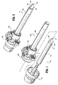
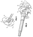
- FIG. 3 is a perspective view with parts separated of the obturator assembly;
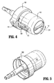
- FIG. 4 is a perspective view of the obturator housing of the obturator assembly;
- FIG. 5 is a second perspective view of the obturator housing of the obturator assembly;
- FIG. 6 is a side cross-sectional view of the obturator housing of the obturator assembly illustrating the activator member in an initial position corresponding to a first mode of operation of the obturator assembly;
- FIGS. 7-8 are perspective views of the obturator housing with the housing cover removed;
- FIG. 9 is an enlarged perspective view of the control member of the obturator housing;
- FIGS. 10-11 are additional perspective views of the obturator housing with the housing cover removed;
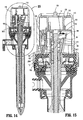
- FIG. 12 is a side cross-sectional view of the obturator assembly illustrating the latch member in an unactuated position;
- FIG. 13 is an enlarged isolated view of the indicated area of detail of FIG. 12 illustrating the relationship of the components of the latch member in the unactuated position;
- FIG. 14 is a side cros-sectional view of the trocar assembly illustrating the obturator assembly mounted relative to the cannula assembly and the latch member in an actuated position;
- FIG. 15 is an enlarged isolated view of the indicated area of detail of FIG. 14 illustrating the relationship of the components of the latch member in the actuated position;
- FIG. 16 is a side cross-sectional view of the obturator housing illustrating the activator member in-a release position corresponding to a second mode of operation of the obturator assembly;
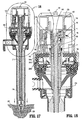
- FIG. 17 is a side cross-sectional view similar to the view of FIG. 14 illustrating the obturator shield of the obturator assembly in a retracted position to expose the obturator blade;
- FIG. 18 is an enlarged isolated view of the indicated area of detail of FIG. 17; and
- FIG. 19 is a side cross sectional view illustrating proximal movement of the indicator collar during movement of the obturator shield to the retracted position.
- Referring now in detail to the drawing figures, in which like references numerals identify similar or identical elements, there is illustrated, in FIGS. 1 and 2, a trocar assembly constructed in accordance with a preferred embodiment of the present disclosure, and designated generally by
reference numeral 10.Trocar assembly 10 is particularly adapted for use in minimally invasive surgical procedures such as endoscopic or laparoscopic procedures. Generally,trocar assembly 10 includes two principal subassemblies, namely,obturator assembly 100 andcannula assembly 1000. -
Cannula assembly 1000 may be any cannula assembly suitable for use in a laparoscopic surgical procedure. In one preferred embodiment,cannula assembly 1000 includescannula housing 1002 andcannula sleeve 1004 extending from thecannula housing 1002. Either or bothcannula housing 1002 andcannula sleeve 1004 may be opaque or transparent in part or in whole and are fabricated from biocompatible metal or polymeric material.Cannula assembly 1000 may include an internal seal such as a duck-bill valve or other zero closure valve adapted to close in the absence of a surgical instrument to prevent passage of insufflation gases through thecannula assembly 1000. -
Trocar assembly 10 may also include aseal assembly 2000 which is preferably releasably mounted tocannula housing 1002. Means for releasably connectingseal assembly 2000 tocannula housing 1002 may include a bayonet coupling, threaded connection, latch, friction fit, tongue and groove arrangements, snap-fit, etc.Seal assembly 2000 includesseal housing 2002 and at least one internal seal which is adapted to form a fluid tight seal about an instrument inserted through theseal assembly 2000. One suitable seal may be -the fabric seal disclosed in commonly assignedU.S. Patent 6,702,787 to Racenet et al. , the entire contents of which are incorporated herein by reference. The seal disclosed in the Racenet '787 patent may be a flat septum-seal having a first layer of resilient material and a second fabric layer juxtaposed relative to the first layer. Further details of the seal-may be ascertained-by reference to the '787 patent.Seal assembly 2000 may or may not be-a component ofcannula assembly 1000. For example, the seal assembly may be a separate, removable assembly. In the alternative, the seal assembly may comprise an integral part of thecannula assembly 1000 and not be removable. - With reference now to FIG. 3, in conjunction-with FIGS. 1-2,
obturator assembly 100 includesobturator housing 102,obturator shaft 104 defining obturator-axis "x" and extending distally from thehousing 102 andobturator shield 106 coaxially mounted about theobturator shaft 104. In general, in a first preferred mode of operation,obturator shield 106 defines adistal shield nose 206 which may be used to enter, penetrate or pass, etc. through tissue through a blunt or dissection entry. Alternatively, in a second mode of operation,obturator shield 106 is permitted to retract in a proximal longitudinal direction to expose the cutting blade disposed at the distal end of theobturator shaft 104. The-details of operation and the configuration ofshield nose 206 and the cutting blade will be discussed hereinbelow. - Referring now to FIGS. 3-5,
obturator housing 102 includeshousing base 108 andhousing cover 110. Once the-appropriate components are positioned therewithin (as described below),housing base 108 may be attached tohousing cover 110 by engaging mating surfaces, for-example, by resilient dependinglatches 112 ofcover 110 interlocking with correspondingly dimensionedlatch openings 114 ofhousing base 108. Preferably, to uniformly connectbase 108 and cover 110, at least threecorresponding latches 112 andopenings 114 are spaced evenly around the circumference of thecover 110 and thebase 108, respectively. Preferably,obturator housing 102 is configured and dimensioned to functionally cooperate with cannulas that range in size, e.g., from about 5 mm to about 15. mm in diameter. - Referring now to FIGS. 4-7, in conjunction with FIG. 3,
obturator housing 102 further includes dial oractivator member 116 andcontrol member 118 both of which are housed within theobturator housing 102.Activator member 116 definesactivator disk 120 andactivator collar 122 extending distally from the-activator disk 120.Activator disk 120 defines raisedtab 124 which is contoured for manual engagement by the fingers of the operator. Raisedtab 124 extends beyond opening 126 ofhousing cover 110. Raisedtab 124 further includes indicia in the form of recessedarrow 128 which identifies the status or position ofactivator member 116.Activator collar 122 includesaxial slot 130 and axial rib 132 (FIG. 7) in-diametrical opposed relation-to theaxial slot 130.Activator member 116 is adapted for limited rotational movement as depicted by directional arrow "a"-about longitudinal axis "x" between initial and-release positions to respectively secure and release obturator shield 106 (FIG. 4). The initial position ofactuator member 116 corresponds to the first mode of operation ofobturator assembly 100 where obturator shield 1-06 is prevented from retracting and thedistal shield nose 206 is used to pass through tissue. FIG. 6 illustrates the initial position ofactivator member 116. The release position corresponds to the second mode of operation ofobturator assembly 100 whereobturator shield 106 is permitted to retract and the cutting blade is used to pierce through tissue. - With reference to FIGS. 6-9, in conjunction with FIG. 3, control-
member 118 is fixed withinobturator housing 102.Control member 118 includescontrol disk 134 and limitingcollar 136 extending from the proximal side or face ofcontrol disk 134.Control disk 134. includes a plurality of alternatingtabs 138 and recesses 140 disposed along the outer periphery of thecontrol disk 134.Tabs 138 are received within corresponding internal recesses 140 (FIG. 6) defined in the inner-wall ofhousing cover 110 to securecontrol member 118 withinobturator housing 102.Control member 118 also includessecondary aperture 142 which is radially or laterally spaced-from longitudinal axis "x".Control disk 134 further includescylindrical shaft mount 144 andspring mount 146 both of which extend from the-distal face of thecontrol disk 134. As best depicted in FIG. 6,shaft mount 144 is generally aligned with longitudinal axis "x" and includesbifurcated tabs 148 andcentral channel 150.Spring mount 146 is laterally or radially spaced from the longitudinal axis "x". - With reference to FIG. 7, limiting
collar 136 ofcontrol member 118 is dimensioned to receive activator-collar 122 ofactivator member 116 in the assembled condition of the components, and to permit theactivator collar 122 to rotate within the limitingcollar 136. Limitingcollar 136 defines recessed-groove 152 which extends about ½ the perimeter of the limitingcollar 136.Axial rib 132 ofactivator member 116 traverses recessedgroove 152 ofcontrol member 118 during rotation of theactivator member 116 between the initial and release positions. As best depicted in FIG. 3, recessedgroove 152 definesabutment walls groove 152. Abutment walls-154, 156 serve as stop(s) to ensure and/or confirm placement ofactivator member 116 in the initial or release position. Specifically,abutment walls member 116 has been moved to either the initial or release position. - Referring now to FIGS. 3, 6, and 7,
obturator housing 100 further includesindicator collar 158. In one preferred arrangement,indicator collar 158 definesinternal channel 160 and hasdistal collar extension 162.Collar extension 162 includesinner tabs 164 on its inner surface.Indicator collar 158 further includestransverse arm 166 extending radially outwardly fromindicator collar 158 and shield position indicator, such-as-indicator flag 168.Transverse arm 166 includesaxial pin 170 which depends in a proximal direction from thearm 166.Axial pin 170 is in general axial alignment withsecondary aperture 142 ofcontrol member 118 and traverses thesecondary aperture 142 during proximal movement of theindicator collar 158.Indicator flag 168 is visible from the exterior ofobturator housing 102 as it extends throughgroove 172 of housing cover 110 (see FIGS. 3 and 4). Preferably,indicator flag 168 is colored to contrast sharply with the surrounding housing components. For example,indicator flag 168 may be red if the surrounding housing components are white or light colored. As best depicted in FIG. 7,indicator collar 158 further includescollar ledge 174 and a pair ofposts 176 formed below theledge 174 and extending radially outwardly from theledge 174. - As best depicted in FIG. 6,
indicator collar 158 is spring biased in the distal direction bycoil spring 178. In particular,coil spring 178 is received withininternal channel 160 ofindicator collar 158 and engagesinternal shelf 160s of theindicator collar 158. The proximal end ofcoil spring 178 is coaxially positioned aboutspring mount 144 depending from the distal face ofcontrol member 118. - Referring now to FIGS. 10-13, in conjunction with FIG. 3,
obturator assembly 100 includes a latching mechanism disposed withinobturator housing 102 to prevent proximal movement ofobturator shield 106 until such time as theobturator assembly 100 is properly mounted to-cannula assembly 1000 and the surgeon is prepared to begin trocar entry. Latching mechanism includes latch-member 180, and release member such asslider 182.Latch member 180 has twovertical legs 184 connected byweb 186. A pair of biasingposts 188 extends outwardly, one for each side oflatch member 180.Collar ledge 174 ofindicator collar 158 is engaged and secured byweb 186 oflatch member 180 when in an unactuated position of thelatch member 180 as depicted in FIGS. 10-13. In the unactuated position oflatch member 180 ofindicator collar 158, theindicator collar 158 and thusobturator shield 106 is retained in a first extended position.Latch member 180 is preferably molded as part ofhousing base 108 in cantilever fashion. However,latch member 180 may be formed as a separate element and secured to base 108 by suitable known techniques. -
Slider 182 includesslider post 190 disposed at its lower end, arming-button 192 extending distally from the distal-face ofslider 182 and a pair ofslider legs 194 which terminate incrooks 196.Crooks 196 defined inslider legs 194 are configured and dimensioned to engageposts 188 oflatch member 180, as shown in FIGS. 10 and 11.Slider 182 is distally biased byslider spring 198 which is maintained in axial alignment byslider post 190 ofslider 182. The proximal end ofslider spring 198 bears against the inner surface ofcontrol member 118 and is maintained in position betweenslider post 190 andspring mount 146 of the control,member 118. (See FIGS. 12 and 13). The distal biasing ofslider 182causes arming button 192 to project throughopening 108a formed inhousing base 108. The lower end ortransverse leg 200 ofslider 182 residues with mountingposts 202 of housing base 108 (FIG. 3). - Referring now to FIGS. 3 and 12-13,
obturator shield 106 hasshield linkage 204 operatively connected thereto and along with theobturator shield 106 defines an outer member ofobturator assembly 100. In one preferred embodiment,shield linkage 204 is connected toobturator shield 106 through an arrangement includingdiametrical tabs 208 extending from the distal end ofshield linkage 204, which-are received within correspondingopenings 210 ofobturator shield 106 in snap relation therewith. Other means for connecting the components ofobturator shield 106 are also envisioned including snap fit arrangements, adhesives, welding tongue and groove arrangements, etc. In other embodiments,obturator shield 106 andshield linkage 204 are a single component. In the assembled condition,shield linkage 204 extends withinhousing base 108 and -is at least partially received-withincollar extension 162.Shield linkage 204 includes a pair of diametrically opposedouter grooves 212 which receiveinner tabs 164 ofcollar extension 162 to operatively connectshield extension 204 andindicator collar 158. Thus, by virtue of connection ofindicator collar 158 withshield linkage 204;obturator shield 106 andshield nose 206 are adapted for-reciprocal axial movement along axis "x" and relative toobturator housing 102 andobturator shaft 104 concurrently with-corresponding movement of theindicator collar 158. - With reference again to FIGS. 1 and 2,
shield nose 206 may be tapered, conical or frusto-conical in configuration, and is adapted to pass- through tissue-and may be capable of cutting or piercing through tissue. In one preferred embodiment,shield nose 206 has an irregular shaped with roundedtip 214. In particular,shield nose 206 is generally tapered in configuration defining a complex curved arrangement. As best depicted in FIG. 2, in a first profile ofshield nose 206, theshield nose 206 includes opposedconcave surfaces 216. In a second profile (viewed at a 90° offset),shield nose 206 definesconvex surfaces 218. This alternating concave and convex arrangement provides a substantially reduced profile (in cross-section) compared to conventional conically shaped obturators thereby providing an enhanced ability to penetrate or pass through tissue layers. Various-radii of curvature are contemplated.Rounded tip 214, by its arcuate configuration, minimizes the potential of undesired or unintended piercing of tissue. Alternatively, it is envisioned that roundedtip 214 may be more pointed to also pierce tissue if desired. This particular configuration ofshield nose 206 is disclosed in commonly assignedU.S. Patent Application Serial No. 11/103,892, filed April 12, 2005 Shield nose 206 also definesknife slot 220. - With reference to FIGS. 3, 6 and 13, the components of
obturator shaft 104 now will be discussed.Obturator shaft 104 includesobturator rod 222 andblade 224 mounted to theobturator rod 222.Obturator rod 222 definesproximal end 226 which passes through opening 160 ofindicator collar 158 and-is received withinshaft mount 144 ofcontrol member 118.Proximal end 226 ofobturator rod 222 includescircumferential recess 228 which receivesbifurcated tabs 148 ofshaft mount 144 ofcontrol member 118 in snap relation therewith. In this manner,obturator rod 104 is fixed toobturator housing 102. - With reference now to FIG. 12. in conjunction with FIG. 3, the distal end of
obturator rod 222 definesobturator knife slot 230 having lockingprojection 232.Knife blade 224 may be secured withinknife slot 230 by reception of lockingprojection 232 within-knife aperture 234. Conventional means including adhesives, cements, etc. are also envisioned.Knife blade 224 is preferably a flat or thin blade and fabricated from stainless steel by a suitable process, e.g., by stamping or metal injection molding and includes opposed cuttingedges 236 which extend to penetratingtip 238.Knife blade 224 is accommodated withinknife slot 220 ofshield nose 206. - With reference now to FIGS. 14-15, a method of use and operation of
trocar assembly 10 will be discussed.Obturator assembly 100 has two modes of operation. In the first mode of operation,obturator shield 106 is locked in its distal position andnose shield 206 is applied against the tissue to penetrate or pass through the tissue through a blunt or dissecting entry. In the second mode,nose shield 206 andobturator shield 106 are permitted to retract to exposeknife blade 224 to contact and penetrate the tissue.Activator member 116 controls operation ofobturator assembly 100 between the two modes. - Initially,
obturator assembly 100 is inserted withincannula assembly 1000 and advanced to whereobturator housing 102 is approximated withseal housing 2002 of theseal assembly 2000.Seal assembly 2000 may comprise a separate part or may be a component ofcannula assembly 1000. Seal-housing 2002 andhousing base 108 ofobturator housing 102 may be appropriately dimensioned to form a friction fit or may be coupled to each other by conventional means including bayonet coupling, tongue-groove, etc. Withobturator housing 102 and sealhousing 2002 approximated, armingbutton 192 ofslider 182 engagesproximal surface 2004 ofseal housing 2002 and is forced upwardly (depicted by directional arrow "u")from the position depicted in FIG. 13 to the position depicted in FIGS. 14-15. During this movement,slider 182 pivots or angulates wherebylegs 194 of theslider 182push latch member 180 in a radial outward direction (depicted by directional arrow "z") such thatweb portion 186 oflatch member 180 is out of axial alignment withledge 174 ofindicator collar 158. In this position,indicator collar 158,obturator shield 106 andshield nose 206 are free to axially move providedactivator member 116 is in the second mode of operation. Withobturator assembly 100 mated withcannula assembly 2000, the surgeon decides whether a blunt bladeless entry or a piercing blade entry is required to access the surgical site. This decision may be predicated on whether or not an initial entry opening has been made within the tissue, and, if so, thereby requiring a bladeless entry into the tissue corresponding to the first mode of operation ofobturator assembly 100. If a bladeless or blunt entry is selected, the surgeon will-position activator member 116 in the initial position of FIG. 6. In this position,activator collar 122 is positioned overaxial pin 170 ofindicator collar 158 and thus prevents proximal retracting movement of theindicator collar 158 andobturator shield 106. Visual confirmation of the positioning ofactivator collar 122 in the initial position is provided-byindicator arrow 128 of raisedtab 124. In one preferred embodiment, the initial position ofactivator collar 122 corresponds to recessedarrow 128 being arranged in diametrical opposed relation toindicator flag 168 as shown in FIG. 6. The surgeon then appliesshield nose 206 to the tissue and exerts a distal force on theassembly 10.Shield nose 206 passes through tissue, e.g., by a blunt dissecting action, to access the underlying surgical site, e.g., the abdominal cavity.Obturator assembly 100 may be removed fromcannula assembly 1000 and surgery may-be performed with instruments introduced withincannula assembly 1000. - If a bladed entry is required corresponding to the second mode of operation,
activator member 116 is selectively moved from the initial position of FIG. 6 to the release position of FIG. 16 by rotating theactivator member 116 about longitudinal axis "x" such that recessedarrow 128 of theactivator member 116 is aligned withindicator flag 168 thereby providing visual confirmation of the positioning ofactivator member 116. Engagement ofaxial rib 122 ofactivator member 116 with wall 156 (FIG. 3) ofcontrol member 118 also provides tactile confirmation of the positioning ofactivator member 116 in the release position. In the release position,axial slot 130 ofactivator collar 122 is in general alignment withaxial pin 170 ofindicator collar 158. - With reference now to FIGS. 17-19, the surgeon begins to insert
trocar assembly 10 through the body wall of the patient.Shield nose 206 contacts the tissue "t" and is driven upwardly to cause theshield nose 206,obturator shield 106, andindicator collar 158 to move proximally (depicted by directional arrow "v") against the bias ofcoil spring 178. As discussed hereinabove,obturator assembly 100 must be properly-mated withseal assembly 2000 such that the-latching mechanism is activated to permit retraction ofobturator shield 106. During the proximal movement ofindicator collar 158,axial pin 170 of theindicator collar 158 traversessecondary aperture 142 ofcontrol member 118 and traverses-axial slot 130 ofactivator member 116. (FIG. 19) Such movement exposesobturator blade 224 to incise the tissue. This armed condition ofobturator assembly 100 is visually verified by the proximal location ofindicator flag 168 ofindicator collar 158. In addition, proximal movement ofindicator collar 158 causesposts 176 of theindicator collar 158 to ride along outer surfaces 194a oflegs 194 ofslider 182 to thereby move theslider 182 at least radially inwardly and upwardly (as shown by the directional arrows "r" and "v", respectively) in a general aligned position relative to the obturator axis "x" and disengaged fromlatch member 180. (i.e.,crooks 196 ofslider legs 194disengage posts 188 of latch member 180). Withobturator blade 224 exposed, the surgeon may apply a distally-directed force toobturator assembly 100 to cause penetration through the tissue. - Once
knife blade 224 andshield nose 206 pass through the body wall of the patient,indicator collar 158, obturator shield 106-and theshield nose 206 move distally under the influence ofcoil spring 178 whereby theshield nose 206 coversblade 224 as shown in FIG. 14. Theobturator assembly 100 may be removed fromcannula assembly 1000 and surgery is performed with instruments inserted throughcannula assembly 1000. It is noted that upon removal ofobturator assembly 100,ledge 174 ofindicator collar 158 moves into engagement withweb portion 186 oflatch member 180. Concurrently with this movement,slider 182, which is aligned relative to axis "x" as discussed hereinabove, is driven distally under the influence ofcoil spring 198. In the respective positions ofindicator collar 158 andslider 182 depicted in FIG. 13,collar ledge 174 ofindicator collar 158 securely engagesweb 186 oflatch member 180 to secure shield nose-206 in its extended position. This-feature ensures that the removedobturator assembly 100 will-not be armed. - Except where noted otherwise, the materials utilized in the components of the presently disclosed trocar assembly generally include materials such as, for example, ABS, polycarbonate, stainless steel, titanium and any other suitable biocompatible metals and/or polymeric materials. A preferred ABS material is CYCOLAC which is available from General Electric. A preferred polycarbonate material is also available from General Electric under the trademark LEXAN. An alternative polycarbonate material which may be utilized is CALIBRE polycarbonate available from Dow Chemical Company. The polycarbonate materials may be partially glass filled for added strength.
- Although the illustrative embodiments of the present disclosure have been described herein with reference-to- the accompanying drawings, it is to be understood that the disclosure is-not limited to those precise embodiments, and that various other changes and modifications may be effected therein by one skilled in the art without departing from the scope or spirit of the disclosure.
Claims (18)
- An obturator assembly for penetrating tissue and being at least partially positionable within a cannula assembly, which comprises:an-obturator housing;an-obturator shaft connected to the obturator housing and defining a longitudinal axis, and-proximal and distal ends;a penetrating member-adjacent the distal end of the obturator shaft;an obturator shield mounted about the obturator-shaft and having a distal shield nose, the obturator shield being adapted for longitudinal movement between an extended position where the penetration member is substantially enclosed within the shield nose and a retracted position where the penetrating member is at least partially exposed from the shield nose; anda manually manipulative member mounted to the obturator housing and adapted for rotational movement about the longitudinal axis and relative to the obturator housing between an initial position corresponding to a first mode of operation where the obturator shield is secured in the extended position and the shield nose is used to penetrate tissue, and a release position corresponding to a second mode of operation operatively releasing the obturator shield to permit the obturator shield to move to the retracted position thereof to expose the penetrating member for penetrating the tissue.
- The obturator assembly according to claim 1 further including a latch member disposed-within the obturator housing, the latch member in operative engagement with the obturator shield to secure the obturator shield -in the extended position thereof, the latch member being actuable to release the obturator shield to thereby permit movement of the obturator shield toward the retracted position provided the manually manipulative member is in the release position thereof.
- The obturator assembly according to claim 2 further comprising a release member mounted to the obturator housing and operatively coupled with the latch member, the release member positioned to engage-the cannula-assembly upon mating of the obturator housing and the cannula assembly to thereby displace the release member and cause actuation of the latch member.
- The obturator assembly according to claim 1 including an indicator member operatively connected to the obturator shield, the indicator member being adapted for longitudinal movement with the obturator shield and for providing visual confirmation to the operator of the positioning of the obturator shield.
- The obturator assembly according to claim 4 wherein the manually manipulative member is in operative engagement with the indicator member when in the initial position of the manually manipulative member to secure the obturator shield in the-extended position and being operatively disengaged from the indicator member when in the release position of the manually manipulative member to permit movement of the obturator shield to the retracted position.
- The obturator assembly according to claim 5 including an indicator collar disposed within the obturator housing and mounted to the obturator shield, the indicator collar having the indicator member mounted thereto and being adapted for longitudinal movement with the obturator shield.
- The obturator assembly according to claim 1 including stop-means associated with the obturator housing for confirming positioning of the manually manipulative member at the initial position and the release position.
- The obturator assembly according to claim 1 including a control member mounted in fixed relation to the obturator housing and operatively associated with the manually manipulative member, one of the control member and the manually manipulative member including a groove and the other of the control member and the manually manipulative member including a pin, the pin traversing the groove during rotation of the manually manipulative member between the initial and release position thereof whereby terminating ends of the groove correspond to the initial and release position of the manually manipulative member.
- The obturator assembly according to claim 1 wherein the penetrating-member is an obturator blade connected to the obturator shaft.
- The obturator assembly according to claim 1 wherein the obturator shield is normally biased toward the extended position.
- An obturator assembly for penetrating tissue and being at least partially positionable within a cannula assembly, which comprises:an obturator housing defining a longitudinal axis;an obturator shaft connected to the obturator housing;a penetrating member adjacent the distal end of the obturator shaft;an obturator shield mounted about the penetrating member and having a shield nose adapted to penetrate tissue, the obturator shield being adapted for longitudinal movement between an extended position where the shield nose substantially encloses the penetrating member and a retracted position to at least partially expose the penetrating member;a latch member disposed within the obturator housing and in operative engagement with the obturator shield to secure the obturator shield in the extended position thereof, the latch member being actuable to release the obturator shield to permit movement of the-obturator shield toward the retracted position thereof; anda manually manipulative member mounted to the obturator housing and adapted to be selectively moved by the operator relative to the obturator housing between an initial position corresponding to a first mode of operation securing the obturator shield in the extended position whereby the shield nose is utilized to pass through tissue,-and a release position corresponding to a second mode of operation operatively releasing the obturator shield to permit the obturator shield to move to the retracted position thereof upon actuation of the latch member to expose the penetrating member to permit the penetrating member to engage and pass through the tissue.
- The obturator assembly according to claim 11 wherein the manually manipulative member is adapted for rotational movement relative to the obturator housing to move between the initial position and the release position.
- The-obturator assembly according to claim 11 further comprising a release member mounted-to the obturator housing and operatively coupled with the latch member, the release member positioned to engage the cannula assembly upon mating of the obturator housing and the cannula assembly to thereby displace the release member and cause actuation of the latch member.
- The obturator assembly according to claim 12 including an indicator member operatively connected to the obturator shield, the indicator member being adapted for longitudinal movement with the obturator shield and for providing visual confirmation to the operator of the positioning of the obturator shield.
- The obturator assembly according to claim 14 wherein the manually manipulative member is in operative engagement with the- indicator member when in the initial position of the manually manipulative member to secure the obturator shield in the extended position and being operatively disengaged from the indicator member when in the release position of the manually manipulative member to permit movement of the obturator shield to the retracted position provided the latch member is actuated.
- A trocar assembly, which comprises:a cannula including a cannula housing and a cannula sleeve extending from the cannula housing; andan obturator assembly at least partially positionable within the cannula, the obturator assembly including:an obturator housing;an obturator shaft connected to the obturator housing;an obturator blade connected to the obturator shaft;an obturator shield coaxially mounted about the obturator blade and being adapted for longitudinal movement between a first position substantially enclosing the obturator blade and a second position to at least partially expose the obturator blade; anda manually manipulative member mounted to the obturator housing and adapted to be selectively moved by the operator relative to the obturator housing between an initial position corresponding to a first mode of operation where a generally blunt leading end of the obturator shield is used to penetrate tissue, and a release-position corresponding to a second mode of operation operatively releasing the obturator shield to permit the obturator shield to move to the retracted position thereof to at least partially expose the obturator blade for piercing through tissue.
- The trocar assembly according to claim 16 further including a latch member disposed within- the obturator housing and in operative engagement with the obturator shield to secure the obturator shield in the extended position thereof, the latch member-being actuable to release the obturator shield upon approximating the obturator housing and the cannula housing.
- The trocar assembly according to claim 16 wherein the manually manipulative member is adapted for rotational movement relative to the obturator housing to move between the initial position and the release position.
Applications Claiming Priority (1)
| Application Number | Priority Date | Filing Date | Title |
|---|---|---|---|
| US81924406P | 2006-07-06 | 2006-07-06 |
Publications (3)
| Publication Number | Publication Date |
|---|---|
| EP1875874A2 true EP1875874A2 (en) | 2008-01-09 |
| EP1875874A3 EP1875874A3 (en) | 2009-03-25 |
| EP1875874B1 EP1875874B1 (en) | 2013-02-27 |
Family
ID=38607190
Family Applications (1)
| Application Number | Title | Priority Date | Filing Date |
|---|---|---|---|
| EP07252535A Expired - Fee Related EP1875874B1 (en) | 2006-07-06 | 2007-06-22 | Two mode trocar assembly |
Country Status (5)
| Country | Link |
|---|---|
| US (1) | US9113953B2 (en) |
| EP (1) | EP1875874B1 (en) |
| JP (1) | JP5225619B2 (en) |
| AU (1) | AU2007203083B2 (en) |
| CA (1) | CA2593833A1 (en) |
Cited By (2)
| Publication number | Priority date | Publication date | Assignee | Title |
|---|---|---|---|---|
| EP2044899A3 (en) * | 2007-10-05 | 2010-04-21 | Tyco Healthcare Group LP | Two-mode bladeless trocar assembly |
| FR3040870A1 (en) * | 2015-09-11 | 2017-03-17 | Ab Medica | SUPPORT DEVICE FOR MEDICAL INSTRUMENT |
Families Citing this family (17)
| Publication number | Priority date | Publication date | Assignee | Title |
|---|---|---|---|---|
| JP5437233B2 (en) * | 2007-04-11 | 2014-03-12 | コヴィディエン リミテッド パートナーシップ | Visualization entry trocar with moving blade |
| AU2008242277B2 (en) * | 2007-04-17 | 2013-06-20 | Covidien Lp | Visual obturator with handle |
| US8940007B2 (en) * | 2007-04-18 | 2015-01-27 | Covidien Lp | Trocar assembly with obturator dissector |
| US8192353B2 (en) * | 2007-10-05 | 2012-06-05 | Tyco Healthcare Group Lp | Visual obturator |
| US8740925B2 (en) * | 2008-10-10 | 2014-06-03 | Covidien Lp | Trocar assembly |
| US9572597B2 (en) | 2013-09-24 | 2017-02-21 | Covidien Lp | Optical trocar tip protector |
| US9545264B2 (en) * | 2014-06-06 | 2017-01-17 | Surgiquest, Inc. | Trocars and obturators |
| EP3766440A1 (en) | 2014-09-18 | 2021-01-20 | Mayo Foundation for Medical Education and Research | Soft tissue cutting device |
| US9743952B2 (en) | 2015-02-18 | 2017-08-29 | Jon Kiev | Device and method for access to interior body regions |
| US10588658B2 (en) | 2015-07-25 | 2020-03-17 | Aok Innovations, Llc | Device and method for access to interior body regions |
| CN106901809A (en) * | 2017-03-14 | 2017-06-30 | 张宪祥 | A kind of magnet-type laparoscopic surgery sleeve puncture outfit |
| US10864055B2 (en) | 2017-10-13 | 2020-12-15 | Sonex Health, Inc. | Tray for a soft tissue cutting device and methods of use |
| US10779857B2 (en) | 2018-04-04 | 2020-09-22 | Aok Innovations, Llc | Device and method for access to interior body regions |
| EP3908215B1 (en) | 2019-01-11 | 2023-08-02 | Mayo Foundation for Medical Education and Research | Micro-invasive surgical device |
| USD989961S1 (en) | 2021-04-30 | 2023-06-20 | Sonex Health, Inc. | Soft tissue cutting device |
| US11963692B2 (en) | 2021-04-30 | 2024-04-23 | Aok Innovations, Llc | Body cavity access device |
| CN113229871A (en) * | 2021-06-21 | 2021-08-10 | 广东脉搏医疗科技有限公司 | Conveying steel cable and conveying system |
Citations (3)
| Publication number | Priority date | Publication date | Assignee | Title |
|---|---|---|---|---|
| US6319266B1 (en) | 2000-03-16 | 2001-11-20 | United States Surgical Corporation | Trocar system and method of use |
| US6702787B2 (en) | 1997-05-02 | 2004-03-09 | Tyco Healthcare Group Lp | Trocar seal system |
| US10389205B2 (en) | 2016-01-11 | 2019-08-20 | Nidec Motor Corporation | Motor programming tool |
Family Cites Families (63)
| Publication number | Priority date | Publication date | Assignee | Title |
|---|---|---|---|---|
| US4535773A (en) * | 1982-03-26 | 1985-08-20 | Inbae Yoon | Safety puncturing instrument and method |
| US4601710B1 (en) * | 1983-08-24 | 1998-05-05 | United States Surgical Corp | Trocar assembly |
| US4654030A (en) * | 1986-02-24 | 1987-03-31 | Endotherapeutics | Trocar |
| US4902280A (en) * | 1986-10-17 | 1990-02-20 | United States Surgical Corporation | Trocar |
| US5030206A (en) * | 1986-10-17 | 1991-07-09 | United States Surgical Corporation | Trocar |
| US4931042A (en) * | 1987-10-26 | 1990-06-05 | Endotherapeutics | Trocar assembly with improved latch |
| GB8816033D0 (en) * | 1988-07-06 | 1988-08-10 | Ethicon Inc | Improved safety trocar |
| US5215526A (en) * | 1988-07-06 | 1993-06-01 | Ethicon, Inc. | Safety trocar |
| US5217441A (en) * | 1989-08-15 | 1993-06-08 | United States Surgical Corporation | Trocar guide tube positioning device |
| US5114407A (en) * | 1990-08-30 | 1992-05-19 | Ethicon, Inc. | Safety mechanism for trocar |
| US5318580A (en) * | 1990-09-11 | 1994-06-07 | Origin Medsystems, Inc. | Retractable trocar |
| DE69105900T2 (en) * | 1990-10-05 | 1995-05-24 | United States Surgical Corp | Security trocar. |
| US5116353B1 (en) * | 1990-10-05 | 1996-09-10 | Digital Voice Systems Inc | Safety trocar |
| US5226426A (en) * | 1990-12-18 | 1993-07-13 | Inbae Yoon | Safety penetrating instrument |
| US5350393A (en) * | 1992-01-06 | 1994-09-27 | Inbae Yoon | Safety trocar penetrating instrument |
| US5645557A (en) * | 1990-12-18 | 1997-07-08 | Yoon; Inbae | Safety penetrating instrument with triggered penetrating member retraction and safety member protrusion |
| US5431635A (en) * | 1990-12-18 | 1995-07-11 | Yoon; Inbae | Safety penetrating instrument having a triggered safety member for establishing an endoscopic portal in an anatomical cavity wall |
| US5645556A (en) * | 1990-12-18 | 1997-07-08 | Yoon; Inbae | Safety penetrating instrument with triggered penetrating member retraction and single or multiple safety member protrusion |
| US5578053A (en) * | 1993-06-24 | 1996-11-26 | Yoon; Inbae | Safety needle instrument having a triggered safety member |
| US5827315A (en) * | 1994-01-04 | 1998-10-27 | Yoon; Inbae | Safety penetrating instrument with penetrating member protected after penetration to predetermined depth |
| US5104382A (en) * | 1991-01-15 | 1992-04-14 | Ethicon, Inc. | Trocar |
| US5474539A (en) * | 1991-02-07 | 1995-12-12 | Origin Medsystems, Inc. | Trocar with retracting tip |
| US5152754A (en) * | 1991-02-15 | 1992-10-06 | Minnesota Mining And Manufacturing Company | Trocar |
| US5295993A (en) * | 1991-04-30 | 1994-03-22 | United States Surgical Corporation | Safety trocar |
| US5645076A (en) * | 1991-08-14 | 1997-07-08 | Yoon; Inbae | Automatic retractable safety penetrating instrument |
| US5360405A (en) | 1991-11-27 | 1994-11-01 | Inbae Yoon | Automatic retractable safety penetrating instrument |
| US5312354A (en) * | 1991-11-04 | 1994-05-17 | American Cyanamid Company | Safety trocar instrument having a retractable point actuated by a trigger sleeve |
| US5158552A (en) * | 1991-11-04 | 1992-10-27 | American Cyanamid Company | Safety trocar instrument having a retractable trocar actuated by relief of pressure on the trocar point |
| US5441513A (en) * | 1992-03-12 | 1995-08-15 | United States Surgical Corporation | Retracting tip trocar assembly |
| US5248298A (en) * | 1992-04-16 | 1993-09-28 | Ethicon, Inc. | Insert for shielded trocar |
| US5290243A (en) * | 1992-07-16 | 1994-03-01 | Technalytics, Inc. | Trocar system |
| US5246425A (en) * | 1992-09-21 | 1993-09-21 | Daniel Hunsberger | Trocar and cannula assembly |
| US5275583A (en) * | 1992-10-05 | 1994-01-04 | Lawrence Crainich | Trocar assembly with independently acting shield means |
| US5356421A (en) * | 1992-10-07 | 1994-10-18 | United States Surgical Corporation | Safety trocar with locking handles |
| US5314417A (en) * | 1992-12-22 | 1994-05-24 | Ethicon, Inc. | Safety trocar |
| US5263937A (en) * | 1993-02-11 | 1993-11-23 | Shipp John I | Trocar with profile to reduce insertion force |
| US5387197A (en) * | 1993-02-25 | 1995-02-07 | Ethicon, Inc. | Trocar safety shield locking mechanism |
| US5462532A (en) * | 1993-03-17 | 1995-10-31 | Origin Medsystems, Inc. | Trocar with safety sensing sleeve |
| US5868773A (en) * | 1993-03-29 | 1999-02-09 | Endoscopic Concepts, Inc. | Shielded trocar with safety locking mechanism |
| US5364372A (en) * | 1993-03-29 | 1994-11-15 | Endoscopic Concepts, Inc. | Trocar and cannula |
| US5346459A (en) * | 1993-04-14 | 1994-09-13 | Minnesota Mining And Manufacturing Company | Trocar |
| US5417705A (en) * | 1993-05-14 | 1995-05-23 | Habley Medical Technology Corp. | Obturator with rotating, resettable safety shield |
| US5437643A (en) * | 1993-05-17 | 1995-08-01 | Ethicon, Inc. | Safety interposer for surgical instruments |
| WO1994027513A1 (en) * | 1993-05-28 | 1994-12-08 | Origin Medsystems, Inc. | Retracting tip trocar with plunger sensor |
| US5411515A (en) * | 1993-07-29 | 1995-05-02 | Habley Medical Technology Corporation | Obturator with rotating, self-locking and resettable safety shield |
| US5364365A (en) * | 1993-08-30 | 1994-11-15 | Surgin Surgical Instrumentation, Inc. | Safety device for laparoscopic instruments |
| AU7727194A (en) * | 1993-09-07 | 1995-03-27 | Invamed, Inc. | Safety shielded, reusable trocar |
| US5538509A (en) * | 1994-01-31 | 1996-07-23 | Richard-Allan Medical Industries, Inc. | Trocar assembly |
| US5545150A (en) * | 1994-05-06 | 1996-08-13 | Endoscopic Concepts, Inc. | Trocar |
| CA2149290C (en) * | 1994-05-26 | 2006-07-18 | Carl T. Urban | Optical trocar |
| US5522833A (en) * | 1994-08-29 | 1996-06-04 | Ethicon Endo-Surgery, Inc. | Retractable obturator for a trocar |
| CA2168694A1 (en) * | 1995-03-20 | 1996-09-21 | Wayne P. Young | Trocar assembly with electrocautery penetrating tip |
| US5807338A (en) * | 1995-10-20 | 1998-09-15 | United States Surgical Corporation | Modular trocar system and methods of assembly |
| US5674237A (en) * | 1996-03-06 | 1997-10-07 | Ott; Henryk | Safety trocar |
| US5669885A (en) * | 1996-05-14 | 1997-09-23 | United States Surgical Corporation | Trocar assembly with spring-loaded mechanism |
| US5984941A (en) * | 1997-02-13 | 1999-11-16 | Endoscopic Concepts, Inc. | Trocar |
| US5904699A (en) * | 1997-09-19 | 1999-05-18 | Ethicon Endo-Surgery, Inc. | Trocar for penetration and skin incision |
| US6017356A (en) * | 1997-09-19 | 2000-01-25 | Ethicon Endo-Surgery Inc. | Method for using a trocar for penetration and skin incision |
| US6036711A (en) * | 1998-02-18 | 2000-03-14 | United States Surgical Corporation | Reusable cannula |
| ES2272269T3 (en) * | 1999-03-16 | 2007-05-01 | United States Surgical Corporation | TROCAR SYSTEM. |
| DE60140278D1 (en) | 2000-08-08 | 2009-12-03 | Tyco Healthcare | Shaped trocar seal |
| JP3928929B2 (en) * | 2002-01-24 | 2007-06-13 | 株式会社トップ | Trocar |
| JP4642769B2 (en) * | 2003-10-17 | 2011-03-02 | タイコ ヘルスケア グループ リミテッド パートナーシップ | Expandable surgical access device |
-
2007
- 2007-06-22 US US11/821,344 patent/US9113953B2/en not_active Expired - Fee Related
- 2007-06-22 EP EP07252535A patent/EP1875874B1/en not_active Expired - Fee Related
- 2007-06-26 JP JP2007168052A patent/JP5225619B2/en not_active Expired - Fee Related
- 2007-07-02 AU AU2007203083A patent/AU2007203083B2/en not_active Ceased
- 2007-07-05 CA CA002593833A patent/CA2593833A1/en not_active Abandoned
Patent Citations (3)
| Publication number | Priority date | Publication date | Assignee | Title |
|---|---|---|---|---|
| US6702787B2 (en) | 1997-05-02 | 2004-03-09 | Tyco Healthcare Group Lp | Trocar seal system |
| US6319266B1 (en) | 2000-03-16 | 2001-11-20 | United States Surgical Corporation | Trocar system and method of use |
| US10389205B2 (en) | 2016-01-11 | 2019-08-20 | Nidec Motor Corporation | Motor programming tool |
Cited By (4)
| Publication number | Priority date | Publication date | Assignee | Title |
|---|---|---|---|---|
| EP2044899A3 (en) * | 2007-10-05 | 2010-04-21 | Tyco Healthcare Group LP | Two-mode bladeless trocar assembly |
| US8002788B2 (en) | 2007-10-05 | 2011-08-23 | Tyco Healthcare Group Lp | Two-mode bladeless trocar assembly |
| US8211135B2 (en) | 2007-10-05 | 2012-07-03 | Tyco Healthcare Group Lp | Two-mode bladeless trocar assembly |
| FR3040870A1 (en) * | 2015-09-11 | 2017-03-17 | Ab Medica | SUPPORT DEVICE FOR MEDICAL INSTRUMENT |
Also Published As
| Publication number | Publication date |
|---|---|
| US20080009894A1 (en) | 2008-01-10 |
| AU2007203083A1 (en) | 2008-01-24 |
| JP2008012303A (en) | 2008-01-24 |
| JP5225619B2 (en) | 2013-07-03 |
| EP1875874A3 (en) | 2009-03-25 |
| US9113953B2 (en) | 2015-08-25 |
| AU2007203083B2 (en) | 2012-07-05 |
| CA2593833A1 (en) | 2008-01-06 |
| EP1875874B1 (en) | 2013-02-27 |
Similar Documents
| Publication | Publication Date | Title |
|---|---|---|
| EP1875874B1 (en) | Two mode trocar assembly | |
| US8211135B2 (en) | Two-mode bladeless trocar assembly | |
| CA2550878C (en) | Trocar assembly with rotatable obturator housing | |
| EP2142115B1 (en) | Trocar assembly with obturator dissector | |
| EP2129413B1 (en) | Trocar assembly with obturator and retractable stylet | |
| US20100016878A1 (en) | Trocar assembly with obturator and retractable stylet | |
| AU2013201687B2 (en) | Trocar assembly with obturator dissector |
Legal Events
| Date | Code | Title | Description |
|---|---|---|---|
| PUAI | Public reference made under article 153(3) epc to a published international application that has entered the european phase |
Free format text: ORIGINAL CODE: 0009012 |
|
| AK | Designated contracting states |
Kind code of ref document: A2 Designated state(s): AT BE BG CH CY CZ DE DK EE ES FI FR GB GR HU IE IS IT LI LT LU LV MC MT NL PL PT RO SE SI SK TR |
|
| AX | Request for extension of the european patent |
Extension state: AL BA HR MK YU |
|
| PUAL | Search report despatched |
Free format text: ORIGINAL CODE: 0009013 |
|
| AK | Designated contracting states |
Kind code of ref document: A3 Designated state(s): AT BE BG CH CY CZ DE DK EE ES FI FR GB GR HU IE IS IT LI LT LU LV MC MT NL PL PT RO SE SI SK TR |
|
| AX | Request for extension of the european patent |
Extension state: AL BA HR MK RS |
|
| 17Q | First examination report despatched |
Effective date: 20090921 |
|
| 17P | Request for examination filed |
Effective date: 20090825 |
|
| AKX | Designation fees paid |
Designated state(s): DE ES FR GB IE IT |
|
| GRAP | Despatch of communication of intention to grant a patent |
Free format text: ORIGINAL CODE: EPIDOSNIGR1 |
|
| RAP1 | Party data changed (applicant data changed or rights of an application transferred) |
Owner name: COVIDIEN LP |
|
| GRAS | Grant fee paid |
Free format text: ORIGINAL CODE: EPIDOSNIGR3 |
|
| GRAA | (expected) grant |
Free format text: ORIGINAL CODE: 0009210 |
|
| AK | Designated contracting states |
Kind code of ref document: B1 Designated state(s): DE ES FR GB IE IT |
|
| REG | Reference to a national code |
Ref country code: GB Ref legal event code: FG4D |
|
| REG | Reference to a national code |
Ref country code: IE Ref legal event code: FG4D |
|
| REG | Reference to a national code |
Ref country code: DE Ref legal event code: R096 Ref document number: 602007028672 Country of ref document: DE Effective date: 20130425 |
|
| PG25 | Lapsed in a contracting state [announced via postgrant information from national office to epo] |
Ref country code: ES Free format text: LAPSE BECAUSE OF FAILURE TO SUBMIT A TRANSLATION OF THE DESCRIPTION OR TO PAY THE FEE WITHIN THE PRESCRIBED TIME-LIMIT Effective date: 20130607 |
|
| PG25 | Lapsed in a contracting state [announced via postgrant information from national office to epo] |
Ref country code: IT Free format text: LAPSE BECAUSE OF FAILURE TO SUBMIT A TRANSLATION OF THE DESCRIPTION OR TO PAY THE FEE WITHIN THE PRESCRIBED TIME-LIMIT Effective date: 20130227 |
|
| PLBE | No opposition filed within time limit |
Free format text: ORIGINAL CODE: 0009261 |
|
| STAA | Information on the status of an ep patent application or granted ep patent |
Free format text: STATUS: NO OPPOSITION FILED WITHIN TIME LIMIT |
|
| 26N | No opposition filed |
Effective date: 20131128 |
|
| REG | Reference to a national code |
Ref country code: DE Ref legal event code: R097 Ref document number: 602007028672 Country of ref document: DE Effective date: 20131128 |
|
| REG | Reference to a national code |
Ref country code: FR Ref legal event code: PLFP Year of fee payment: 10 |
|
| PGFP | Annual fee paid to national office [announced via postgrant information from national office to epo] |
Ref country code: DE Payment date: 20160524 Year of fee payment: 10 Ref country code: GB Payment date: 20160527 Year of fee payment: 10 Ref country code: IE Payment date: 20160524 Year of fee payment: 10 |
|
| PGFP | Annual fee paid to national office [announced via postgrant information from national office to epo] |
Ref country code: FR Payment date: 20160526 Year of fee payment: 10 |
|
| REG | Reference to a national code |
Ref country code: DE Ref legal event code: R119 Ref document number: 602007028672 Country of ref document: DE |
|
| GBPC | Gb: european patent ceased through non-payment of renewal fee |
Effective date: 20170622 |
|
| REG | Reference to a national code |
Ref country code: IE Ref legal event code: MM4A |
|
| REG | Reference to a national code |
Ref country code: FR Ref legal event code: ST Effective date: 20180228 |
|
| PG25 | Lapsed in a contracting state [announced via postgrant information from national office to epo] |
Ref country code: DE Free format text: LAPSE BECAUSE OF NON-PAYMENT OF DUE FEES Effective date: 20180103 Ref country code: IE Free format text: LAPSE BECAUSE OF NON-PAYMENT OF DUE FEES Effective date: 20170622 Ref country code: GB Free format text: LAPSE BECAUSE OF NON-PAYMENT OF DUE FEES Effective date: 20170622 |
|
| PG25 | Lapsed in a contracting state [announced via postgrant information from national office to epo] |
Ref country code: FR Free format text: LAPSE BECAUSE OF NON-PAYMENT OF DUE FEES Effective date: 20170630 |