EP1859634B1 - System and method for rfid reader operation - Google Patents
System and method for rfid reader operation Download PDFInfo
- Publication number
- EP1859634B1 EP1859634B1 EP06738597A EP06738597A EP1859634B1 EP 1859634 B1 EP1859634 B1 EP 1859634B1 EP 06738597 A EP06738597 A EP 06738597A EP 06738597 A EP06738597 A EP 06738597A EP 1859634 B1 EP1859634 B1 EP 1859634B1
- Authority
- EP
- European Patent Office
- Prior art keywords
- read
- tag
- tag reader
- image
- reader
- Prior art date
- Legal status (The legal status is an assumption and is not a legal conclusion. Google has not performed a legal analysis and makes no representation as to the accuracy of the status listed.)
- Active
Links
Images


Classifications
-
- G—PHYSICS
- G06—COMPUTING; CALCULATING OR COUNTING
- G06K—GRAPHICAL DATA READING; PRESENTATION OF DATA; RECORD CARRIERS; HANDLING RECORD CARRIERS
- G06K7/00—Methods or arrangements for sensing record carriers, e.g. for reading patterns
- G06K7/0008—General problems related to the reading of electronic memory record carriers, independent of its reading method, e.g. power transfer
-
- Y—GENERAL TAGGING OF NEW TECHNOLOGICAL DEVELOPMENTS; GENERAL TAGGING OF CROSS-SECTIONAL TECHNOLOGIES SPANNING OVER SEVERAL SECTIONS OF THE IPC; TECHNICAL SUBJECTS COVERED BY FORMER USPC CROSS-REFERENCE ART COLLECTIONS [XRACs] AND DIGESTS
- Y10—TECHNICAL SUBJECTS COVERED BY FORMER USPC
- Y10S—TECHNICAL SUBJECTS COVERED BY FORMER USPC CROSS-REFERENCE ART COLLECTIONS [XRACs] AND DIGESTS
- Y10S345/00—Computer graphics processing and selective visual display systems
- Y10S345/903—Modular display
Definitions
- the invention relates to a tag reader as described in the precharacterizing part of claim 1 for reading wireless electronic tags disposed in a read area and a method of wireless electronic tag reading as described in the precharacterizing part of claim 8.
- the field of the present disclosure relates to operating methods and techniques for systems employing electronic identification tags such as radio frequency identification (RFID) tags,
- RFID radio frequency identification
- methods and apparatus are described herein for improving and facilitating operation of electronic tag and RFID reading systems.
- RFID technology uses electromagnetic energy as a medium through which to send information.
- RFID tags are affixed to various articles for allowing identification of Items in a sales transaction or tracking movement of the articles through a business location.
- a receiver and some type of transmitter, an antenna, and memory are implemented.
- RFID tags are enabled to receive, store, and transmit article-identifying data to/from a remote data base station without the manual handling operations as is required in most bar code systems.
- RFID tags may be read-only or read-write.
- Passive RFID tags may be implemented without batteries and draw their power from the radio frequency (RF) energy transmitted from the reader.
- RFID tags may be low or high frequency depending on the application.
- the present inventors have recognized the desirability of providing feedback on the operation of RFID reading systems for improving operational efficiency and performance.
- a data reader displays a graphical representation or sets of icons indicating symbol reading activity.
- the display may illustrate an alphanumeric display or suggest that other visual indications, as well as audio and tactile indication may be possible.
- the RFID reader is actuated by a single trigger pull, with the reader continuing to read multiple RFID tags in the read zone as long as the trigger is held until a terminating event occurs.
- an apparatus and method provides real-time feedback of the progress of a multiple RFID tag reading operation.
- Fig. 1 is a diagrammatic view of a combined RFID system comprised of an RFID reader, optical code reader and data terminal.
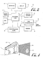
- Fig. 2 is a simplified block diagram of an RFID system of Fig. 1 .
- Fig. 3 is a screen shot for an input scheme of a program for the system of Fig. 1 .
- Fig. 4 is a diagram of an RFID system illustrating an RFID reading field relative to an RFID tag.
- Fig. 5 is flow chart of a method of RFID feedback operation.
- Fig. 6 is a screen shot for an input scheme of an audio portion for the system of Fig. 1 ),
- Fig. 7 is a screen shot for an input scheme of report settings for the system of Fig. 1 .
- Fig. 8 is a screen shot for an input scheme of read limits for the system of Fig. 1 .
- Fig. 9 illustrates the data terminal of Fig. 1 with a detailed view of a screen shot for a display illustrating a image of a field of view with a preferred RFID read zone interposed thereon.
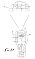
- Fig. 10 illustrates a data terminal as in Fig. 9 with an alternate targeting format.
- Fig. 1 illustrates a handheld combination device 10 comprising a portable terminal section 12, a handle section 18 and an RFID antenna section 20.
- the portable terminal section 12 includes a display screen 13 and a keypad section 14 for providing control or data input into the terminal, as well as displaying information to the user.
- the terminal 12 includes a front window 15 through which a data reading device such as an imaging reader or laser scanner is operative to read optical codes or otherwise to detect an image within a field of view.
- the reader 10 is preferably a combination system with the various functions controlled by the terminal 12 as selected by the user via input using the touch display screen 13 or the keypad section 14. Within a particular mode of operation, the user may activate a particular read operation by actuating the trigger 19 located on the front of the handle 18 or a scan key trigger 25 on the keyboard 14, or another virtual switch on the touch screen 13.
- the reader sends out an interrogation signal.
- an RFID tag (whether it is a passive tag or an active tag) may respond by sending out a return signal containing the tag data/information.
- the RFID reader then senses the return signal and processes the signal to obtain the data.
- An RFID read operation in a handheld device is typically defined by a trigger pull and a single read command sent to the reader to read all tags within the RF field.
- an RFID reader may read multiple tags within a single read operation or tag inventory operation.
- each of the tags seen in a given read operation is read sequentially according to a suitable protocol such as query response protocol or air interface protocol (AIP).
- AIP air interface protocol
- the present inventors have determined that all tags in a read volume are not always successfully read during a single read operation.
- the RFID read operation is extended beyond a single read attempt by continuing to perform multiple reads, that is, multiple interrogation sequences are undertaken out until a terminating criteria has been met.
- One such method may be directed to a handheld reader including the steps of (1) pointing a handheld RFID reader toward a read area; (2) actuating a trigger on the handheld RFID reader to commence reading RFID tags by the substeps of (a) performing a first read operation, wherein the read operation comprises interrogating and sensing one or more RFID tags in the read area, (b) continuing with a subsequent read operation comprising reading one or more tags in the read area which may be different tags than the tags read during the first read operation, and (c) the RFID reader discontinuing subsequent read operations once a termination criteria is met. And if the reader is moved as between the first read operation and the second read operation, the read area or direction of read may also be changed.
- Such a terminating criteria may comprise any one or more of the following:
- a second trigger pull in this methodology the user would actuate read operation by a first trigger pull and release the trigger and the read operation would continue until a subsequent (second) trigger pull notifying the system to terminate.
- the system would have knowledge that a discrete number of RFID tags are expected in a particular read operation. For example, when reading a pallet of items in a warehouse, the system might know that 50 items (i.e., 50 RFID tags to be read) are expected to be located on the pallet and once each of the 50 RFID tags are read, operation is terminated.
- the pallet itself may include its own RFID tag with the RFID tag itself including information as to how many items are included on the pallet. Alternately the information may be stored in a look-up table accessible to the reader terminal. Once the RFID tag on the pallet is read, the terminal can access the lookup table and obtain the number of RFID tags that are expected to be on the pallet.
- Input field filling the RFID data being collected may be used to fill out certain input fields such as on an inventory check list. Once all the input fields on the inventory check list are filled, the read operation may be terminated.
- the read operation may be monitored via network and RFID read data may be reported to the host via the network where it is analyzed and a terminating signal may then originate from the host via the network.
- Termination delay timer the reader may have delay in termination after the trigger is released.
- New tag read timer the reader may automatically continue to read and analyze whether new tags have been read.
- a timeout timer restarts each time a new tag is detected. As long as a new tag is detected, it would be desirable to continue searching for and reading additional tags. If a new tag is not read within a given time, such as 10 seconds, read operation is terminated.
- Minimum Tag Count the minimum number of tags to attempt to read during the inventory operation.
- Each of the timeout times, shut off delay, or other system variables may be programmable variables that may be selected by the user, defaults in the system, selected by the host computer over the network, or may be actively varied by the system as selected by given criteria due to prior to read operations or other inputs.
- This operating scheme allows the operator to move the reader in a single operation to read all the tags such as on a shelf or on a product pallet.
- the operator can relocate the direction of the antenna so as to better locate and read RFID tags at different positions and orientations. For example, if the items on the pallet contain water or metal, then the RFID tags located on an opposite side of the pallet from the reader are difficult to read because the water or metal tends to absorb the electromagnetic fields.
- the operator can reorient the reading of the RFID tag so that the RF signal need not pass through the water/metal.
- the shelf may be too wide (or there may be multiple shelves) to enable the reader to read all the items on the shelf from a single position.
- the operator may activate the reader, holding the trigger, and moving the reader in a sweeping motion along the shelf, or each one of a plurality of shelves) so as to read each item on the shelf.
- the RFID tag data is reported as it is read and becomes available prior to the end of the overall read operation.
- the reader responds with an audible beep tone each time a new RFID tag is read and reported.
- duplicate tag reads are removed by a suitable method.
- the user may also be notified by actuation of an LED 17 such as by flashing green each time a new tag is read. The repetitive beeps and/or lighting of the LED indicator 17 provide information to the operator of the progress of the read operation.
- the plurality of tags are read quickly at the beginning of the operation, but as more and more of the tags are read, fewer tags remain to be read and thus the frequency of the beeps indicating new tags being read slows down eventually notifying the operator that there are no further tags to be read when a beep has not been heard within a reasonable time frame.
- the operator then terminates the operation by releasing the trigger.
- This trigger holding operation enables the operator to move the read field such as walking around a pallet or painting a field systematically moving the reader across a shelf of items to provide the reader with the opportunity to read each of the items from an optimal orientation.
- software application could examine an intermediate report of tag data received and, following a given criteria, decide to terminate read operation.
- One such criteria may comprise searching for a specific tagged item from amongst many items in a read area.
- Duplicate tag data may also be removed by keeping track of what tags have already been read, comparing a new tag read to the list of tags already read and not reporting a duplicate tag if determined that the tag had already been written.
- an application at a higher level looking at the results may allow the software to analyze the data and potentially control continuing read operation.
- Fig. 2 illustrates a schematic of the components of the combined reader 10 of Fig. 1 .
- the reader 10 includes a processing core 11 which may comprise the microprocessor within the terminal 12. Connected to the processor core 11 are the keyboard 14 that provides for information input and the display 13 which displays information and also acts as a touch screen for inputting commands or data into the system. Under the control of the processing core 11 the system includes two indicators audio/beeper 24 and an indicator light 17.
- the indicator may comprise a light-emitting diode (LED) or other suitable visible light indicator. Alternately, the indicator may be a separate high-intensity LED 17a on the top of the housing (as shown in Fig. 1 ) or may be a suitable indicator appearing on the display 13, or by additional electro-mechanical means.
- LED light-emitting diode
- the indicator may be a separate high-intensity LED 17a on the top of the housing (as shown in Fig. 1 ) or may be a suitable indicator appearing on the display 13,
- the reader 10 has multiple data input devices, namely a barcode scanner or imaging reader 15 and an RFID interrogator 20. Attached to the interrogator is the RFID antenna 22.
- the system communicates to a computer or another host via communications 16 which is preferably wireless connection.
- the display 13 provides a versatile and convenient control interface for the system 10.
- the user may select which of the reading mechanisms to be used.
- the system 10 includes two triggers, namely the pistol trigger 19 on the handle 18 and the scan key trigger 25 on the keyboard 14 of the terminal 12. Additional triggers may provide by other keys on the keyboard 14, by "virtual" key/triggers displayed on the touch screen 13, or by additional electro-merhanical means.
- the terminal operates in a Microsoft WindowsTM environment.
- onscreen instructions are used to calibrate the touch screen 13.
- a set of trigger options are accessed in the display 40 shown in Fig. 3 .
- the pistol trigger may be enabled or disabled and the data reading device selected which would be operable by the pistol trigger in this setting.
- the RFID reader is selected to be actuated by the pistol trigger 19 and the barcode scanner is set to be actuated by the scan key 25 by the buttons 44.
- the unit 10 includes an imaging reader or imaging system, such a system could be activated by a given trigger (element 19 or element 25) as selected in this onscreen selection process.
- RFID tags may be read by the steps of:
- Fig. 4 illustrates a preferred orientation for aiming the reader 10 and an RFID tag 32 such that the RFID section 20 points directly at the tag 32 providing a read field 30 encompassing the tag.
- Fig. 5 is a flow chart of a method 50 as described in the following steps.
- Step 52A start either via a hardware trigger pull at Step 52A or via a signal from an operating/software protocol at Step 528.
- Step 56 Instructing the RFID interrogator to inventory tags at Step 56.
- the RFID interrogator emits a signal instructing RFID tags to transmit their data.
- the interrogator then receives the signals from the tags.
- Step 58 determines whether any new tags have been read; if "No” continue scanning at step 62 and if "Yes” proceed to step 60.
- Step 58 the system compares a tag read to a list of tags previously read and only registers a new read when the tag read has not been previously indicated during the current inventory.
- This indication may be actuating an audible tone at beeper 24 and/or actuating the LED 17 (or 17a) to provide a visual indicator.
- Step 62 read termination determining whether all the tags have been read. There are several methods by which this condition may be determined. Starting timer at step 56.
- This timer is started at Step 54 or 56 and runs continuously as tags are read.
- This timeout may be programmable and set to a value depending on system requirements or may be a variable adjusted by the system depending upon certain read criteria such as average RFID signal strength detected (for example, if the signal strength is low, then a longer timeout is set).
- This timer is re-started each at Step 60 each time a new tag is detected as being read. As long as new tags are being read, it is desired to permit the reader to continue reading tags.
- This timeout may also be programmable and set to a value depending on system requirements or may be a variable adjusted by the system depending upon certain read criteria such as average RFID signal strength detected (for example, if the signal strength is low, then a longer timeout is set).
- Step 70 if no read termination has been indicated, returning to Step 56 and continue tag inventory.
- Step 72 if a read termination has been indicated, ending RFID tag inventory.
- the method of Fig. 5 includes multiple termination events 62, 64, 66, 68, 70.
- the order of these events may be re-arranged, or one or more of the steps may be omitted depending on the application.
- Which of these termination steps (or combination of steps) is applied may be user-selected via a suitable program interface. For example, the system may terminate the read only via release of the trigger of Step 68 with Steps 62, 64, 60, 70 omitted.
- Fig. 6 is a screen shot 100 of display 13 illustrating an input scheme for selecting the audio indicators.
- a volume slide button 102 enables the user to select a "beep" volume from zero to a maximum.
- the "Good Read” type is shown, the others may include “All Tags Read” type (as from Step 62).
- the tone may be selected by slide button 107
- the "beep" duration may be selected by slide button 108
- the number of "beeps” may be selected by slide button 108. For example, a triple beep may be sounded to indicated that all tags have been read.
- Fig. 7 is a screen shot 110 of display 13 illustrating an input scheme for report settings.
- Slide button 112 selects how often RFID tag data is reported to an application. When set to a specific number of tags, data is reported when at least the selected number of new tags have been read. When set to the minimum (i.e. one tag) each time a new tag is read, the tag is reported, that is every new tag is reported once read. When set to infinite, data Is only reported when a painting operation is complete. Selecting the checkbox 114 for Read Class 0 Tags or checkbox 116 for Read Class 1 Tags selectively enables or disables the device to read each class of RFID tags. Improved performance may be achieved by enabling only the class of tags which will be used, if known.
- Fig. 8 is a screen shot 120 of display 13 illustrating an input scheme for selecting read limit values:
- Step 66 the maximum amount of time spent waiting for a new tag to be read after the last new tag that had previously been read. If set to infinite, then the reading/searching for new tags will continue until the trigger is released, Total Read Timeout occurs, or the minimum number of tags has been read.
- Minimum Tag Count 126 the minimum number of tags to attempt to read. If set to infinite, then the reading/searching for new tags will continue until trigger is released or one of the timeout conditions is met.
- Audible indicators such as a "beep" tone at a given pitch may signal the successful read of an RFID tag.
- a signal is preferably sounded only when a new tag is read. Once all the tags are determined to have been read, then an alternate signal may be sounded, such as a second beep tone of a different pitch, or a multiple beep tone, to provide a signal to the operator that the reading operation is complete.
- the display 13 may also provide feedback during the inventory reading process such as:
- a quantity of tags read during the operation -- various formats of display may implemented such as: (a) a simple increasing number in the form of the numerical representation (e.g. 1, 2, 3 .. 50), or (b) a bar graph with either a single bar or multiple bars.
- a countdown of the number of items to be read In this example, the expected number of items to be read within an Inventory read operation is known or obtained. Then the display screen 13 shows the beginning number of items expected (e.g, 50) counting down toward zero (e.g. 50, 49, 48 . . . 3, 2, 1, 0).
- the display may show a numeric countdown (counting down toward zero, e.g. 10, 9, 8, 7, 6, 5, 4, 3, 2, 1, 0), or a graphical representation such as an hourglass with decreasing amounts of material at the top of the hourglass as the remaining time decreases.
- the countdown amount may be from Total Read Timeout 122 or New Tag Timeout 124.
- Fig. 9 illustrates an embodiment of the invention in which the unit 10 is provided with an imager and an image display.
- the operator may select an operational mode whereby an image 130 of the field of view of the RFID reader Is acquired by the imager 15 and displayed on the display screen 13.
- the image 130 may be larger than the effective read zone of the RFID reader 20, but the display screen 13 may further provide feedback of the effective read region such as an outline of the effective read zone (shown by dashed lines 132).
- the dashed lines 132 may thus comprise a targeting pattern indicative of an effective read area of the reader 20.
- Fig. 10 illustrates another embodiment of the invention similar to the embodiment of Fig. 9 .
- the unit 10 is also provided with an imager and an image display.
- the imager can acquire an image of an item in the field of view, in this instance the item comprises a plurality of boxes 150.
- the operator may select an operational mode whereby an image 131 of the field of view of the reader is acquired by the imager 15 and displayed on the display screen 13.
- the image 131 may be larger than the effective read zone of the RFID reader 20, but the display screen 13 may further provide feedback of the effective read region such as a shaded region 140.
- the region 140 may comprise a unique color such as red and is preferably sufficiently transparent such that the item 150 is visible therethrough.
- the region 140 may comprise a targeting pattern indicative of an effective read area of the reader 20.
- the region 140 may be any suitable shape, the triangular shape illustrated in the figure being just an example.
Description
- The invention relates to a tag reader as described in the precharacterizing part of
claim 1 for reading wireless electronic tags disposed in a read area and a method of wireless electronic tag reading as described in the precharacterizing part of claim 8. - The field of the present disclosure relates to operating methods and techniques for systems employing electronic identification tags such as radio frequency identification (RFID) tags, In particular, methods and apparatus are described herein for improving and facilitating operation of electronic tag and RFID reading systems.
- RFID technology uses electromagnetic energy as a medium through which to send information. Typically, RFID tags are affixed to various articles for allowing identification of Items in a sales transaction or tracking movement of the articles through a business location. In a typical RFID tag system, a receiver and some type of transmitter, an antenna, and memory are implemented. Through the use of these components, RFID tags are enabled to receive, store, and transmit article-identifying data to/from a remote data base station without the manual handling operations as is required in most bar code systems. RFID tags may be read-only or read-write. Passive RFID tags may be implemented without batteries and draw their power from the radio frequency (RF) energy transmitted from the reader. RFID tags may be low or high frequency depending on the application.
- The present inventors have recognized the desirability of providing feedback on the operation of RFID reading systems for improving operational efficiency and performance.
- From
US 6,318,636 a data reader displays a graphical representation or sets of icons indicating symbol reading activity. Alternately, the display may illustrate an alphanumeric display or suggest that other visual indications, as well as audio and tactile indication may be possible. - It is an object of the invention to improve the tag reader according to the precharacterizing part of
claim 1 and the method according to the precharacterizing part of claim 8 such as to provide a visible indication to an operator of the read are a of a tag reader by displaying on the display an actual image of the reader's field of view thereby enabling the operator to readily aim the reader and adjust for proximity of the tag to the reader, direction and interposition of objects therebetween. - This is achieved by the features in the characterizing part of
claim 1 and 8, respectively.
Preferred embodiments are described in the dependent claims. - In one, embodiment, the RFID reader is actuated by a single trigger pull, with the reader continuing to read multiple RFID tags in the read zone as long as the trigger is held until a terminating event occurs. In another embodiment, an apparatus and method provides real-time feedback of the progress of a multiple RFID tag reading operation.
- Additional aspects and advantages will be apparent from the following detailed description of preferred embodiments, which proceeds with reference to the accompanying drawings.
-
Fig. 1 is a diagrammatic view of a combined RFID system comprised of an RFID reader, optical code reader and data terminal. -
Fig. 2 is a simplified block diagram of an RFID system ofFig. 1 . -
Fig. 3 is a screen shot for an input scheme of a program for the system ofFig. 1 . -
Fig. 4 is a diagram of an RFID system illustrating an RFID reading field relative to an RFID tag. -
Fig. 5 is flow chart of a method of RFID feedback operation. -
Fig. 6 is a screen shot for an input scheme of an audio portion for the system ofFig. 1 ), -
Fig. 7 is a screen shot for an input scheme of report settings for the system ofFig. 1 . -
Fig. 8 is a screen shot for an input scheme of read limits for the system ofFig. 1 . -
Fig. 9 illustrates the data terminal ofFig. 1 with a detailed view of a screen shot for a display illustrating a image of a field of view with a preferred RFID read zone interposed thereon. -
Fig. 10 illustrates a data terminal as inFig. 9 with an alternate targeting format. - For the purposes of the present disclosure, certain of the descriptions will be described with respect to an RFID reader reading RFID tags, but the disclosure may also be applicable to other electronic tags systems such as combined RFID/EAS tag systems or other wireless electronic tag systems, and combined RFID and optical code readers. The disclosure may also apply to a system wherein an EAS or RFID tag circuit or enabler circuit is integrated into the circuitry of the electronic item itself.
-
Fig. 1 illustrates ahandheld combination device 10 comprising aportable terminal section 12, ahandle section 18 and anRFID antenna section 20. Theportable terminal section 12 includes adisplay screen 13 and akeypad section 14 for providing control or data input into the terminal, as well as displaying information to the user. Theterminal 12 includes afront window 15 through which a data reading device such as an imaging reader or laser scanner is operative to read optical codes or otherwise to detect an image within a field of view. Thereader 10 is preferably a combination system with the various functions controlled by theterminal 12 as selected by the user via input using thetouch display screen 13 or thekeypad section 14. Within a particular mode of operation, the user may activate a particular read operation by actuating thetrigger 19 located on the front of thehandle 18 or ascan key trigger 25 on thekeyboard 14, or another virtual switch on thetouch screen 13. - During a read operation in response to a trigger pull, the reader sends out an interrogation signal. Upon receipt of the interrogation signal, an RFID tag (whether it is a passive tag or an active tag) may respond by sending out a return signal containing the tag data/information. The RFID reader then senses the return signal and processes the signal to obtain the data.
- An RFID read operation in a handheld device is typically defined by a trigger pull and a single read command sent to the reader to read all tags within the RF field. As such, an RFID reader may read multiple tags within a single read operation or tag inventory operation. Typically, each of the tags seen in a given read operation is read sequentially according to a suitable protocol such as query response protocol or air interface protocol (AIP).
- The present inventors have determined that all tags in a read volume are not always successfully read during a single read operation. In a first preferred embodiment, the RFID read operation is extended beyond a single read attempt by continuing to perform multiple reads, that is, multiple interrogation sequences are undertaken out until a terminating criteria has been met. One such method may be directed to a handheld reader including the steps of (1) pointing a handheld RFID reader toward a read area; (2) actuating a trigger on the handheld RFID reader to commence reading RFID tags by the substeps of (a) performing a first read operation, wherein the read operation comprises interrogating and sensing one or more RFID tags in the read area, (b) continuing with a subsequent read operation comprising reading one or more tags in the read area which may be different tags than the tags read during the first read operation, and (c) the RFID reader discontinuing subsequent read operations once a termination criteria is met. And if the reader is moved as between the first read operation and the second read operation, the read area or direction of read may also be changed.
- There are various mechanisms and methods the terminating criteria. Such a terminating criteria may comprise any one or more of the following:
- 1. Releasing of the trigger: in one configuration the operator would hold the trigger and the reading operation would continue as long as the trigger is held. In such a method, the operator need not release and re-actuate the trigger in order to affect continued read operations.
- 2. A second trigger pull: in this methodology the user would actuate read operation by a first trigger pull and release the trigger and the read operation would continue until a subsequent (second) trigger pull notifying the system to terminate.
- 3. Software decision, wherein several embodiments are envisioned:
- A. Use of a counting mechanism -- in one method the system would have knowledge that a discrete number of RFID tags are expected in a particular read operation. For example, when reading a pallet of items in a warehouse, the system might know that 50 items (i.e., 50 RFID tags to be read) are expected to be located on the pallet and once each of the 50 RFID tags are read, operation is terminated. In a subset of this section, the pallet itself may include its own RFID tag with the RFID tag itself including information as to how many items are included on the pallet. Alternately the information may be stored in a look-up table accessible to the reader terminal. Once the RFID tag on the pallet is read, the terminal can access the lookup table and obtain the number of RFID tags that are expected to be on the pallet.
- B. Input field filling: the RFID data being collected may be used to fill out certain input fields such as on an inventory check list. Once all the input fields on the inventory check list are filled, the read operation may be terminated.
- C. External controller: The read operation may be monitored via network and RFID read data may be reported to the host via the network where it is analyzed and a terminating signal may then originate from the host via the network.
- D. Termination delay timer: the reader may have delay in termination after the trigger is released.
- E. New tag read timer: the reader may automatically continue to read and analyze whether new tags have been read. A timeout timer restarts each time a new tag is detected. As long as a new tag is detected, it would be desirable to continue searching for and reading additional tags. If a new tag is not read within a given time, such as 10 seconds, read operation is terminated.
- F. Minimum Tag Count: the minimum number of tags to attempt to read during the inventory operation.
- Each of the timeout times, shut off delay, or other system variables may be programmable variables that may be selected by the user, defaults in the system, selected by the host computer over the network, or may be actively varied by the system as selected by given criteria due to prior to read operations or other inputs.
- This operating scheme allows the operator to move the reader in a single operation to read all the tags such as on a shelf or on a product pallet. By being able to move the reader during the tag inventory operation, the operator can relocate the direction of the antenna so as to better locate and read RFID tags at different positions and orientations. For example, if the items on the pallet contain water or metal, then the RFID tags located on an opposite side of the pallet from the reader are difficult to read because the water or metal tends to absorb the electromagnetic fields. By moving around to an opposite side of the pallet, the operator can reorient the reading of the RFID tag so that the RF signal need not pass through the water/metal. In the shelf example, the shelf may be too wide (or there may be multiple shelves) to enable the reader to read all the items on the shelf from a single position. The operator may activate the reader, holding the trigger, and moving the reader in a sweeping motion along the shelf, or each one of a plurality of shelves) so as to read each item on the shelf.
- Preferably the RFID tag data is reported as it is read and becomes available prior to the end of the overall read operation. In one embodiment, the reader responds with an audible beep tone each time a new RFID tag is read and reported. Preferably duplicate tag reads are removed by a suitable method. The user may also be notified by actuation of an
LED 17 such as by flashing green each time a new tag is read. The repetitive beeps and/or lighting of theLED indicator 17 provide information to the operator of the progress of the read operation. For example, where there are multiple tags intended to be read during the operation, the plurality of tags are read quickly at the beginning of the operation, but as more and more of the tags are read, fewer tags remain to be read and thus the frequency of the beeps indicating new tags being read slows down eventually notifying the operator that there are no further tags to be read when a beep has not been heard within a reasonable time frame. The operator then terminates the operation by releasing the trigger. This trigger holding operation enables the operator to move the read field such as walking around a pallet or painting a field systematically moving the reader across a shelf of items to provide the reader with the opportunity to read each of the items from an optimal orientation. - In other termination criteria, software application could examine an intermediate report of tag data received and, following a given criteria, decide to terminate read operation. One such criteria may comprise searching for a specific tagged item from amongst many items in a read area.
- Duplicate tag data may also be removed by keeping track of what tags have already been read, comparing a new tag read to the list of tags already read and not reporting a duplicate tag if determined that the tag had already been written.
- By reporting tag data prior to the end of the read operation, an application at a higher level looking at the results may allow the software to analyze the data and potentially control continuing read operation.
-
Fig. 2 illustrates a schematic of the components of the combinedreader 10 ofFig. 1 . Thereader 10 includes aprocessing core 11 which may comprise the microprocessor within theterminal 12. Connected to theprocessor core 11 are thekeyboard 14 that provides for information input and thedisplay 13 which displays information and also acts as a touch screen for inputting commands or data into the system. Under the control of theprocessing core 11 the system includes two indicators audio/beeper 24 and anindicator light 17. The indicator may comprise a light-emitting diode (LED) or other suitable visible light indicator. Alternately, the indicator may be a separate high-intensity LED 17a on the top of the housing (as shown inFig. 1 ) or may be a suitable indicator appearing on thedisplay 13, or by additional electro-mechanical means. - The
reader 10 has multiple data input devices, namely a barcode scanner orimaging reader 15 and anRFID interrogator 20. Attached to the interrogator is theRFID antenna 22. The system communicates to a computer or another host viacommunications 16 which is preferably wireless connection. - The
display 13 provides a versatile and convenient control interface for thesystem 10. In a preferred operation, the user may select which of the reading mechanisms to be used. In preferred configuration, thesystem 10 includes two triggers, namely thepistol trigger 19 on thehandle 18 and the scankey trigger 25 on thekeyboard 14 of the terminal 12. Additional triggers may provide by other keys on thekeyboard 14, by "virtual" key/triggers displayed on thetouch screen 13, or by additional electro-merhanical means. - In one operating scheme, the terminal operates in a Microsoft Windows™ environment. Once the unit is powered on, onscreen instructions are used to calibrate the
touch screen 13. Accessing the configuration settings, a set of trigger options are accessed in thedisplay 40 shown inFig. 3 . Using this screen, the pistol trigger may be enabled or disabled and the data reading device selected which would be operable by the pistol trigger in this setting. For example in the settings ofbuttons 42 as shown inFig. 3 , the RFID reader is selected to be actuated by thepistol trigger 19 and the barcode scanner is set to be actuated by thescan key 25 by thebuttons 44. Alternately, where theunit 10 includes an imaging reader or imaging system, such a system could be activated by a given trigger (element 19 or element 25) as selected in this onscreen selection process. - Once the
system 10 has been enabled to read RFID tags, an application is opened on the terminal 12 that accepts data In a suitable format as received from RFID tags such as, for example, keyboard wedge data which is accepted by Microsoft Wordpad™ program. Once the program is activated, RFID tags may be read by the steps of: - (1) Aiming the device toward the tag desired to be read.
- (2) Pressing the
trigger 19, thefront LED 17 turns orange indicating that theRFID reader 20 is in operation. - (3) The device sounds an audible beep as tags are read.
- (4) The RFID read is entered into the application.
- (5) When the read is finished, the
LED 17 is turned off and a final beep is sounded indicating that the read operation is complete. -
Fig. 4 illustrates a preferred orientation for aiming thereader 10 and anRFID tag 32 such that theRFID section 20 points directly at thetag 32 providing aread field 30 encompassing the tag. -
Fig. 5 is a flow chart of amethod 50 as described in the following steps. - -- System start either via a hardware trigger pull at Step 52A or via a signal from an operating/software protocol at Step 528.
- -- Commencing RFID tag inventory operation at
Step 54. - -- Instructing the RFID interrogator to inventory tags at
Step 56. In this step, the RFID interrogator emits a signal instructing RFID tags to transmit their data. The interrogator then receives the signals from the tags. - -- Determining at
Step 58 whether any new tags have been read; if "No" continue scanning atstep 62 and if "Yes" proceed to step 60. At thisStep 58, the system compares a tag read to a list of tags previously read and only registers a new read when the tag read has not been previously indicated during the current inventory. - -- Indicating a new tag has been read at
Step 60. This indication may be actuating an audible tone atbeeper 24 and/or actuating the LED 17 (or 17a) to provide a visual indicator. - -- Step 62 (read termination) determining whether all the tags have been read. There are several methods by which this condition may be determined. Starting timer at
step 56. - -- Step 64 (read termination) determining whether an operation timeout has occurred. This timer is started at
Step - -- Step 66 (read termination) determining whether a new tag timeout has occurred. This timer is re-started each at
Step 60 each time a new tag is detected as being read. As long as new tags are being read, it is desired to permit the reader to continue reading tags. This timeout may also be programmable and set to a value depending on system requirements or may be a variable adjusted by the system depending upon certain read criteria such as average RFID signal strength detected (for example, if the signal strength is low, then a longer timeout is set). - -- Step 68 (read termination) determining if the trigger has been released.
- -- At
step 70 if no read termination has been indicated, returning to Step 56 and continue tag inventory. - -- At
Step 72, if a read termination has been indicated, ending RFID tag inventory. - The method of
Fig. 5 includesmultiple termination events Step 68 withSteps -
Fig. 6 is a screen shot 100 ofdisplay 13 illustrating an input scheme for selecting the audio indicators. Avolume slide button 102 enables the user to select a "beep" volume from zero to a maximum. There are several audible indicators in the system, and each of these indicators is adjustable, being selected by the drop-down menu 104. The "Good Read" type is shown, the others may include "All Tags Read" type (as from Step 62). Once atype 104 is selected, the tone may be selected byslide button 107, the "beep" duration may be selected byslide button 108, and the number of "beeps" may be selected byslide button 108. For example, a triple beep may be sounded to indicated that all tags have been read. -
Fig. 7 is a screen shot 110 ofdisplay 13 illustrating an input scheme for report settings.Slide button 112 selects how often RFID tag data is reported to an application. When set to a specific number of tags, data is reported when at least the selected number of new tags have been read. When set to the minimum (i.e. one tag) each time a new tag is read, the tag is reported, that is every new tag is reported once read. When set to infinite, data Is only reported when a painting operation is complete. Selecting thecheckbox 114 forRead Class 0 Tags orcheckbox 116 forRead Class 1 Tags selectively enables or disables the device to read each class of RFID tags. Improved performance may be achieved by enabling only the class of tags which will be used, if known. -
Fig. 8 is a screen shot 120 ofdisplay 13 illustrating an input scheme for selecting read limit values: - -- Total Read Timeout 122: the time for which the reader will be allowed to read before terminating the operation. This value corresponds to Step 64 above. If set to infinite, then the reading/searching for new tags will continue until trigger is released, New Tag Timeout occurs, or the minimum number of tags has been read.
- -- New Tag Timeout 124: the amount of time to wait between new tag reads before the inventory operation is terminated. This value corresponds to Step 66 above, the maximum amount of time spent waiting for a new tag to be read after the last new tag that had previously been read. If set to infinite, then the reading/searching for new tags will continue until the trigger is released, Total Read Timeout occurs, or the minimum number of tags has been read.
- -- Minimum Tag Count 126: the minimum number of tags to attempt to read. If set to infinite, then the reading/searching for new tags will continue until trigger is released or one of the timeout conditions is met.
- To improve operability during an inventory reading process, additional feedback may be provided to the operator. Audible indicators such as a "beep" tone at a given pitch may signal the successful read of an RFID tag. As in the above-described embodiment, a signal is preferably sounded only when a new tag is read. Once all the tags are determined to have been read, then an alternate signal may be sounded, such as a second beep tone of a different pitch, or a multiple beep tone, to provide a signal to the operator that the reading operation is complete.
- The
display 13 may also provide feedback during the inventory reading process such as: - 1. A quantity of tags read during the operation -- various formats of display may implemented such as: (a) a simple increasing number in the form of the numerical representation (e.g. 1, 2, 3 .. 50), or (b) a bar graph with either a single bar or multiple bars.
- 2. A countdown of the number of items to be read. In this example, the expected number of items to be read within an Inventory read operation is known or obtained. Then the
display screen 13 shows the beginning number of items expected (e.g, 50) counting down toward zero (e.g. 50, 49, 48 . . . 3, 2, 1, 0). - 3. A display of the amount of operation time remaining. The display may show a numeric countdown (counting down toward zero, e.g. 10, 9, 8, 7, 6, 5, 4, 3, 2, 1, 0), or a graphical representation such as an hourglass with decreasing amounts of material at the top of the hourglass as the remaining time decreases. The countdown amount may be from
Total Read Timeout 122 orNew Tag Timeout 124. - The ability to read a specific electronic tag may be affected by the proximity of the tag to the reader, direction, and interposition of objects therebetween.
Fig. 9 illustrates an embodiment of the invention in which theunit 10 is provided with an imager and an image display. In this embodiment, the operator may select an operational mode whereby animage 130 of the field of view of the RFID reader Is acquired by theimager 15 and displayed on thedisplay screen 13. Theimage 130 may be larger than the effective read zone of theRFID reader 20, but thedisplay screen 13 may further provide feedback of the effective read region such as an outline of the effective read zone (shown by dashed lines 132). The dashedlines 132 may thus comprise a targeting pattern indicative of an effective read area of thereader 20. -
Fig. 10 illustrates another embodiment of the invention similar to the embodiment ofFig. 9 . InFig. 10 , theunit 10 is also provided with an imager and an image display. The imager can acquire an image of an item in the field of view, in this instance the item comprises a plurality ofboxes 150. The operator may select an operational mode whereby animage 131 of the field of view of the reader is acquired by theimager 15 and displayed on thedisplay screen 13. Theimage 131 may be larger than the effective read zone of theRFID reader 20, but thedisplay screen 13 may further provide feedback of the effective read region such as ashaded region 140. Theregion 140 may comprise a unique color such as red and is preferably sufficiently transparent such that theitem 150 is visible therethrough. Theregion 140 may comprise a targeting pattern indicative of an effective read area of thereader 20. Theregion 140 may be any suitable shape, the triangular shape illustrated in the figure being just an example. - Thus the present invention has been set forth in the form of its preferred embodiments. It is nevertheless intended that modifications to the disclosed methods and systems may be made by those skilled in the art without altering the inventive concepts set forth herein. The scope of the present invention should, therefore, be determined only by the following claims.
Claims (23)
- A tag reader (10/20) adapted for reading wireless electronic tags disposed in a read area, comprising:a housing adapted for handheld operation; a display screen (13) disposed on the housing ;an imager (15) for acquiring an image (131) of said read area;the display screen (13) characterized by: being operative to display said image.
- The tag reader (10/20) according to claim 1, wherein the display screen (13) is adapted to display a targeting pattern (132, 140) on said image (131), the targeting pattern (132, 140) being indicative of a representation of an effective read area of the tag reader (10/20).
- The tag reader (10/20) according to claim 2, wherein the targeting pattern (132, 140) comprises an outline of an effective read area superimposed on said image (131).
- The tag reader (10/20) according to claim 2, wherein the targeting pattern (132, 140) comprises a rectangular or triangular outline of an effective read area superimposed over said image.
- The tag reader (10/20) according to claim 2, wherein the targeting pattern (132, 140) comprises a shaded region (140).
- The tag reader (10/20) according to claim 5, wherein the shaded region (140) is sufficiently transparent such that an object (150) being displayed is visible through the shaded region (140).
- The tag reader (10/20) according to any one of claims 1 to 6, wherein the tag reader (10/20) is operative to switch to an operating mode whereby the display screen (13) is activated to display said image.
- A method of wireless electronic tag reading by a tag reader (10/20) in accordance with any of claims 1 to 7, comprising the steps of:pointing said tag reader (10/20) toward a read area;acquiring, from the imager (15), an image;displaying said image on the display screen (13) ;displaying a targeting pattern (132, 140) on the display screen (13), the targeting pattern (132, 140) being indicative of a representation of an effective read area of the tag reader (10/20).
- The method according to claim 8, wherein the targeting pattern (132, 140) comprises a shaped outline (132) of the effective read area superimposed over said image.
- The method according to claim 8 or 9, wherein the targeting pattern (132, 140) comprises a rectangular or triangular outline of the effective read area superimposed on said image.
- The method according to claim 8, wherein the targeting pattern (132, 140) comprises a shaded region (140).
- The method according to claim 11, wherein the shaded region (140) is sufficiently transparent such that an object (150) being displayed is visible through the shaded region (140).
- The method according to any one of claims 8 to 12, further comprising permitting an operator to select an operating mode to activate the display screen (13) to display said image.
- The method according to claim 8, further comprising actuating a trigger (19, 25) on the tag reader (10/20) to commence reading electronic tags by the steps of:performing a first read operation, wherein the read operation comprises interrogating and sensing one or more electronic tags in the read area,continuing with a subsequent read operation comprising interrogating and reading one or more electronic tags in the read area,the tag reader (10/20) discontinuing subsequent read operations once a termination criteria is met.
- The method according to claim 14, further comprising repeating subsequent read operations as long as the trigger (19, 25) is held, wherein the termination criteria is met by releasing the trigger (19, 25).
- The method according to claim 15, wherein upon releasing the trigger (19, 25), delaying the discontinuing subsequent read operations by a given period.
- The method according to claim 14, wherein the termination criteria is met by resetting and restarting a timeout timer when a new electronic tag is read, discontinuing subsequent read operations if the timeout timer expires before a new electronic tag is read.
- The method according to claim 14, wherein the termination criteria is met by counting a total number of distinct electronic tags read during a read operation and discontinuing subsequent read operations if the total number reaches a given value.
- The method according to claim 14, wherein the termination criteria is met by completing input of field filling data.
- The method according to claim 14, wherein the termination criteria is met by actuating the trigger (19, 25) a second time.
- The method according to claim 8, wherein the read area contains multiple electronic tags (32), the method further comprising:activating the tag reader (10/20);reading a plurality of the electronic tags (32) within a single reader activation;notifying an operator of reading operation by sounding an audible signal each time a non-previously read electronic tag (32) is read.
- The method according to claim 21, further comprising discontinuing subsequent read operations once a termination criteria is met, wherein the step of activating the tag reader (10/20) comprises actuating a trigger (19, 25) on the tag reader (10/20) and wherein the termination criteria is met by releasing the trigger (19, 25).
- The method according to claim 8, further comprising:initiating a tag inventory operation;attempting to read an electronic tag (32) within the read area; andif an electronic tag (32) has been read and data from the electronic tag (32) has been obtained, transmitting the data retrieved to a host without terminating reading operations.
Applications Claiming Priority (2)
| Application Number | Priority Date | Filing Date | Title |
|---|---|---|---|
| US11/084,072 US7583178B2 (en) | 2005-03-16 | 2005-03-16 | System and method for RFID reader operation |
| PCT/US2006/009558 WO2006101998A2 (en) | 2005-03-16 | 2006-03-15 | System and method for rfid reader operation |
Publications (3)
| Publication Number | Publication Date |
|---|---|
| EP1859634A2 EP1859634A2 (en) | 2007-11-28 |
| EP1859634A4 EP1859634A4 (en) | 2008-05-21 |
| EP1859634B1 true EP1859634B1 (en) | 2012-12-05 |
Family
ID=37009716
Family Applications (1)
| Application Number | Title | Priority Date | Filing Date |
|---|---|---|---|
| EP06738597A Active EP1859634B1 (en) | 2005-03-16 | 2006-03-15 | System and method for rfid reader operation |
Country Status (4)
| Country | Link |
|---|---|
| US (1) | US7583178B2 (en) |
| EP (1) | EP1859634B1 (en) |
| CN (1) | CN101147404B (en) |
| WO (1) | WO2006101998A2 (en) |
Families Citing this family (49)
| Publication number | Priority date | Publication date | Assignee | Title |
|---|---|---|---|---|
| FR2853857B1 (en) * | 2003-04-16 | 2006-07-14 | Michelin Soc Tech | METHOD AND DEVICE FOR PERFORMING TREATMENT ON A COMPONENT SET OF A VEHICLE WHEEL |
| US7339476B2 (en) * | 2004-11-10 | 2008-03-04 | Rockwell Automation Technologies, Inc. | Systems and methods that integrate radio frequency identification (RFID) technology with industrial controllers |
| US7551081B2 (en) | 2004-11-10 | 2009-06-23 | Rockwell Automation Technologies, Inc. | Systems and methods that integrate radio frequency identification (RFID) technology with agent-based control systems |
| US20060208893A1 (en) * | 2005-02-28 | 2006-09-21 | Anson Gary S | Weight audit methods and systems utilizing data reader |
| US7388491B2 (en) | 2005-07-20 | 2008-06-17 | Rockwell Automation Technologies, Inc. | Mobile RFID reader with integrated location awareness for material tracking and management |
| US7764191B2 (en) | 2005-07-26 | 2010-07-27 | Rockwell Automation Technologies, Inc. | RFID tag data affecting automation controller with internal database |
| US8260948B2 (en) | 2005-08-10 | 2012-09-04 | Rockwell Automation Technologies, Inc. | Enhanced controller utilizing RFID technology |
| US20070052540A1 (en) * | 2005-09-06 | 2007-03-08 | Rockwell Automation Technologies, Inc. | Sensor fusion for RFID accuracy |
| US7510110B2 (en) | 2005-09-08 | 2009-03-31 | Rockwell Automation Technologies, Inc. | RFID architecture in an industrial controller environment |
| US7394358B2 (en) | 2005-09-19 | 2008-07-01 | Datalogic Scanning, Inc. | Method and system for inventory monitoring |
| US7931197B2 (en) | 2005-09-20 | 2011-04-26 | Rockwell Automation Technologies, Inc. | RFID-based product manufacturing and lifecycle management |
| US7446662B1 (en) | 2005-09-26 | 2008-11-04 | Rockwell Automation Technologies, Inc. | Intelligent RFID tag for magnetic field mapping |
| US8025227B2 (en) | 2005-09-30 | 2011-09-27 | Rockwell Automation Technologies, Inc. | Access to distributed databases via pointer stored in RFID tag |
| JP4667218B2 (en) * | 2005-11-30 | 2011-04-06 | 富士通フロンテック株式会社 | Bar code reader |
| US8115600B2 (en) * | 2008-11-19 | 2012-02-14 | Greatbatch Ltd. | RFID detection and identification system including an RFID reader having a limited transmit time and a time-out period to protect a medical device against RFID-associated electromagnetic interference |
| US7821400B2 (en) | 2006-09-29 | 2010-10-26 | Datalogic Scanning, Inc. | System and method for verifying number of wireless tagged items in a transaction |
| EP2126810A4 (en) | 2007-02-21 | 2011-10-26 | Advanced Custom Engineered Systems & Equipment Co | System for monitoring a container and the items therein |
| US20090121897A1 (en) * | 2007-11-14 | 2009-05-14 | Electronic Data Systems Corporation | Apparatus, and method, for facilitating passage at a limited access facility |
| US9070001B2 (en) * | 2008-09-19 | 2015-06-30 | Nxp B.V. | Safe initialization procedure for a communication system |
| US8146798B2 (en) | 2008-11-07 | 2012-04-03 | Advanced Custom Engineered Systems & Equipment Co. | Method and apparatus for monitoring waste removal and administration |
| JP2010231702A (en) * | 2009-03-30 | 2010-10-14 | Brother Ind Ltd | Radio tag communication device |
| US10229568B2 (en) * | 2009-11-26 | 2019-03-12 | Megabyte Limited | Anti-theft RFID system and method thereof |
| GB2475755B (en) * | 2009-11-26 | 2012-01-11 | Chun Sing Matthew Man | Anti-theft RFID system and method thereof |
| EP2372676B1 (en) * | 2010-03-29 | 2017-03-15 | Deutsche Post AG | A sealing system for sealing of doors of transport vehicles |
| US20120013441A1 (en) * | 2010-07-16 | 2012-01-19 | Wal-Mart Stores, Inc. | Method and Apparatus Pertaining to Facilitating the Reading of RFID Tags |
| US10706383B2 (en) * | 2010-07-16 | 2020-07-07 | Walmart Apollo, Llc | Method and apparatus pertaining to module-based scanning of RFID tags |
| US8565107B2 (en) | 2010-09-24 | 2013-10-22 | Hand Held Products, Inc. | Terminal configurable for use within an unknown regulatory domain |
| US8791795B2 (en) | 2010-09-28 | 2014-07-29 | Hand Held Products, Inc. | Terminal for line-of-sight RFID tag reading |
| US20140098234A1 (en) * | 2011-05-18 | 2014-04-10 | Djb Group | Image processing system and related monitoring system |
| US9041518B2 (en) * | 2012-01-26 | 2015-05-26 | Hand Held Products, Inc. | Portable RFID reading terminal with visual indication of scan trace |
| FR2986634A1 (en) * | 2012-02-02 | 2013-08-09 | France Telecom | METHOD AND DEVICE FOR ASSISTING THE POSITIONING OF A NEAR FIELD COMMUNICATION MODULE IN RELATION TO AN ELECTROMAGNETIC TRANSPONDER |
| US9443119B2 (en) | 2012-04-20 | 2016-09-13 | Hand Held Products, Inc. | Portable encoded information reading terminal configured to locate groups of RFID tags |
| US9536219B2 (en) | 2012-04-20 | 2017-01-03 | Hand Held Products, Inc. | System and method for calibration and mapping of real-time location data |
| US9971888B2 (en) * | 2013-03-15 | 2018-05-15 | Id Integration, Inc. | OS security filter |
| US20140327524A1 (en) * | 2013-05-02 | 2014-11-06 | Wal-Mart Stores, Inc. | Method and apparatus pertaining to preconfiguring in facilitating the reading of rfid tags |
| US9251388B2 (en) * | 2013-05-15 | 2016-02-02 | Advanced Custom Engineered Systems & Equipment, Co. | Method for deploying large numbers of waste containers in a waste collection system |
| US10073992B2 (en) | 2013-09-20 | 2018-09-11 | Walmart Apollo, Llc | Method and apparatus pertaining to facilitating the reading of RFID tags |
| USD747715S1 (en) * | 2014-03-21 | 2016-01-19 | Datalogic Ip Tech S.R.L. | Portable computer with barcode reader |
| JP6394504B2 (en) * | 2014-06-13 | 2018-09-26 | 株式会社デンソーウェーブ | RFID reader |
| US10037509B1 (en) | 2014-06-17 | 2018-07-31 | Amazon Technologies, Inc. | Efficient monitoring of inventory items |
| US10176449B1 (en) * | 2014-08-08 | 2019-01-08 | Amazon Technologies, Inc. | Timeout durations for radio frequency identification tags |
| US10061948B2 (en) * | 2014-08-25 | 2018-08-28 | Covidien Lp | Systems and methods for emulating RFID transponders of a plurality of medical devices |
| CN104573588B (en) * | 2014-12-16 | 2018-03-27 | 深圳市海云天科技股份有限公司 | RFID label tag check in phonetic prompt method and system |
| EP3040904B1 (en) | 2014-12-31 | 2021-04-21 | Hand Held Products, Inc. | Portable rfid reading terminal with visual indication of scan trace |
| CN105184454A (en) * | 2015-08-19 | 2015-12-23 | 北京京东方多媒体科技有限公司 | Article management system and article management method |
| US11727363B2 (en) | 2016-03-31 | 2023-08-15 | Advanced Custom Engineered Systems & Equipment Company | Systems and method for interrogating, publishing and analyzing information related to a waste hauling vehicle |
| US10706242B2 (en) * | 2016-06-30 | 2020-07-07 | Intel Corporation | RFID antenna re-location and/or RFID location |
| US10679179B2 (en) * | 2017-04-21 | 2020-06-09 | Sensormatic Electronics, LLC | Systems and methods for an improved tag counting process |
| JP7016573B2 (en) * | 2017-08-09 | 2022-02-07 | 株式会社アスタリスク | Reading system |
Family Cites Families (33)
| Publication number | Priority date | Publication date | Assignee | Title |
|---|---|---|---|---|
| US3972648A (en) * | 1973-12-26 | 1976-08-03 | Sangster Paul B | Well controller and monitor |
| JPS57179834A (en) * | 1981-04-28 | 1982-11-05 | Canon Inc | X-ray image photographing device |
| ZA948824B (en) * | 1993-12-08 | 1995-07-11 | Caterpillar Inc | Method and apparatus for operating geography altering machinery relative to a work site |
| US5513264A (en) | 1994-04-05 | 1996-04-30 | Metanetics Corporation | Visually interactive encoding and decoding of dataforms |
| US5640002A (en) | 1995-08-15 | 1997-06-17 | Ruppert; Jonathan Paul | Portable RF ID tag and barcode reader |
| US6170748B1 (en) | 1997-01-06 | 2001-01-09 | Widata Corporation | Object identification system employing pulsed magnetic field-stimulated, tag-embedded transponder |
| US5883582A (en) * | 1997-02-07 | 1999-03-16 | Checkpoint Systems, Inc. | Anticollision protocol for reading multiple RFID tags |
| US6607134B1 (en) | 1997-07-17 | 2003-08-19 | Symbol Technologies, Inc. | Finger-mounted readers with low power radio frequency communications |
| US6714121B1 (en) | 1999-08-09 | 2004-03-30 | Micron Technology, Inc. | RFID material tracking method and apparatus |
| US6456239B1 (en) | 1999-08-25 | 2002-09-24 | Rf Technologies, Inc. | Method and apparatus for locating mobile tags |
| US6318636B1 (en) | 1999-09-21 | 2001-11-20 | Intermec Ip Corp. | Method and apparatus to read different types of data carriers, such RFID tags and machine-readable symbols, and a user interface for the same |
| US6292525B1 (en) * | 1999-09-30 | 2001-09-18 | Siemens Corporate Research, Inc. | Use of Hilbert transforms to simplify image reconstruction in a spiral scan cone beam CT imaging system |
| DE60143821D1 (en) * | 2000-01-14 | 2011-02-17 | 3M Innovative Properties Co | User interface for a portable RFID reader |
| DE10009545A1 (en) * | 2000-02-23 | 2001-08-30 | Jochen Mueller | Digital camera has display viewing device, attachment elements for removable attachment of telescopic light shaft fully enclosing viewer display surface attached on opposing sides |
| US7117374B2 (en) * | 2000-03-24 | 2006-10-03 | Intermec Ip Corp | Apparatus and method for gathering and utilizing data |
| US20020072395A1 (en) * | 2000-12-08 | 2002-06-13 | Ivan Miramontes | Telephone with fold out keyboard |
| US7221668B2 (en) | 2000-12-22 | 2007-05-22 | Terahop Networks, Inc. | Communications within population of wireless transceivers based on common designation |
| US6745027B2 (en) | 2000-12-22 | 2004-06-01 | Seekernet Incorporated | Class switched networks for tracking articles |
| WO2002065380A2 (en) | 2001-02-12 | 2002-08-22 | Matrics, Inc. | Radio frequency identification architecture |
| NL1017870C2 (en) * | 2001-04-18 | 2002-10-25 | Marc Van Oldenborgh | Method for inverse multiplexing. |
| US6758403B1 (en) | 2001-09-11 | 2004-07-06 | Psc Scanning, Inc. | System for editing data collection device message data |
| US6895196B2 (en) * | 2002-10-08 | 2005-05-17 | Canon Kabushiki Kaisha | Image forming apparatus having reduced power consumption mode and control method therefor |
| JP4196640B2 (en) * | 2002-10-21 | 2008-12-17 | 株式会社日立製作所 | Data conversion method |
| JP3987788B2 (en) * | 2002-11-26 | 2007-10-10 | 富士フイルム株式会社 | Digital camera system |
| US7066388B2 (en) | 2002-12-18 | 2006-06-27 | Symbol Technologies, Inc. | System and method for verifying RFID reads |
| US7063256B2 (en) * | 2003-03-04 | 2006-06-20 | United Parcel Service Of America | Item tracking and processing systems and methods |
| EP1680758A4 (en) | 2003-04-07 | 2008-03-26 | Silverbrook Res Pty Ltd | Obtaining product item assistance |
| KR100543211B1 (en) * | 2003-04-29 | 2006-01-20 | 주식회사 하이닉스반도체 | On dram termination resistance control circuit and its method |
| US7195169B2 (en) | 2003-07-23 | 2007-03-27 | Symbol Technologies, Inc. | Mobile terminal with ergonomic housing |
| US7199719B2 (en) * | 2004-03-24 | 2007-04-03 | Dan Alan Steinberg | RFID tag reader with tag location indicated by visible light beam |
| US7786844B2 (en) | 2005-03-01 | 2010-08-31 | I.D. Systems, Inc. | Mobile portal for RFID applications |
| US7394358B2 (en) | 2005-09-19 | 2008-07-01 | Datalogic Scanning, Inc. | Method and system for inventory monitoring |
| JP2007119239A (en) | 2005-10-31 | 2007-05-17 | Toshiba Tec Corp | Tag reading device |
-
2005
- 2005-03-16 US US11/084,072 patent/US7583178B2/en active Active
-
2006
- 2006-03-15 CN CN2006800085018A patent/CN101147404B/en not_active Expired - Fee Related
- 2006-03-15 EP EP06738597A patent/EP1859634B1/en active Active
- 2006-03-15 WO PCT/US2006/009558 patent/WO2006101998A2/en active Application Filing
Also Published As
| Publication number | Publication date |
|---|---|
| WO2006101998A3 (en) | 2007-05-31 |
| US20060208859A1 (en) | 2006-09-21 |
| WO2006101998A2 (en) | 2006-09-28 |
| EP1859634A4 (en) | 2008-05-21 |
| US7583178B2 (en) | 2009-09-01 |
| CN101147404B (en) | 2012-06-06 |
| CN101147404A (en) | 2008-03-19 |
| EP1859634A2 (en) | 2007-11-28 |
Similar Documents
| Publication | Publication Date | Title |
|---|---|---|
| EP1859634B1 (en) | System and method for rfid reader operation | |
| US7394358B2 (en) | Method and system for inventory monitoring | |
| US20060267730A1 (en) | Apparatus and method for saving power in RFID readers | |
| EP3234750B1 (en) | Floating soft trigger for touch displays on electronic device | |
| US8305192B2 (en) | RFID reader with automatic near/far field interrogation mode switching, and related operating methods | |
| US6234394B1 (en) | Triggered optical reader | |
| US6286762B1 (en) | Method and apparatus to perform a predefined search on data carriers, such as RFID tags | |
| EP2802970B1 (en) | Gesture and motion operation control for multi-mode reading devices | |
| US20060214773A1 (en) | RFID tag singulation | |
| US6286763B1 (en) | Method and apparatus to automatically search data carriers, such as RFID tags and machine-readable symbols | |
| US20060267733A1 (en) | Apparatus and methods for saving power in RFID readers | |
| US11604932B2 (en) | Antenna control apparatus | |
| US20010045460A1 (en) | Method and apparatus to read different types of data carriers, such as RFID tags and machine-readable symbols, and a user interface for the same | |
| US20090096611A1 (en) | Mobile radio frequency identification antenna system and method | |
| US10671277B2 (en) | Floating soft trigger for touch displays on an electronic device with a scanning module | |
| US20090321525A1 (en) | Data capture terminal with multiple readers operable in handheld and hands-free modes of operation | |
| US20100141405A1 (en) | Radio tag reading device and radio tag recognition method using the device | |
| JPH04297953A (en) | Apparatus and method for renewing markings on goods in stock | |
| US10025961B2 (en) | Arrangement for, and method of, enhancing accuracy of data collection for items located in a venue | |
| US11461566B2 (en) | Passive call button and systems and methods associated therewith | |
| CN108363932A (en) | The method for reading bar code and deactivating the thief-proof label of electronic article | |
| JP2006005582A (en) | Receiver and information transmission system |
Legal Events
| Date | Code | Title | Description |
|---|---|---|---|
| PUAI | Public reference made under article 153(3) epc to a published international application that has entered the european phase |
Free format text: ORIGINAL CODE: 0009012 |
|
| 17P | Request for examination filed |
Effective date: 20070907 |
|
| AK | Designated contracting states |
Kind code of ref document: A2 Designated state(s): AT BE BG CH CY CZ DE DK EE ES FI FR GB GR HU IE IS IT LI LT LU LV MC NL PL PT RO SE SI SK TR |
|
| AX | Request for extension of the european patent |
Extension state: AL BA HR MK YU |
|
| A4 | Supplementary search report drawn up and despatched |
Effective date: 20080129 |
|
| RIN1 | Information on inventor provided before grant (corrected) |
Inventor name: WATKINS, PATRICK S. Inventor name: HOUGEN, ROBERT W. Inventor name: STEINKE, KURT E. Inventor name: COHEN, MARK R. |
|
| DA4 | Supplementary search report drawn up and despatched (deleted) | ||
| RA4 | Supplementary search report drawn up and despatched (corrected) |
Effective date: 20080418 |
|
| DAX | Request for extension of the european patent (deleted) | ||
| RBV | Designated contracting states (corrected) |
Designated state(s): DE FR GB |
|
| 17Q | First examination report despatched |
Effective date: 20080701 |
|
| GRAP | Despatch of communication of intention to grant a patent |
Free format text: ORIGINAL CODE: EPIDOSNIGR1 |
|
| GRAS | Grant fee paid |
Free format text: ORIGINAL CODE: EPIDOSNIGR3 |
|
| GRAA | (expected) grant |
Free format text: ORIGINAL CODE: 0009210 |
|
| RAP1 | Party data changed (applicant data changed or rights of an application transferred) |
Owner name: DATALOGIC ADC, INC. |
|
| AK | Designated contracting states |
Kind code of ref document: B1 Designated state(s): DE FR GB |
|
| REG | Reference to a national code |
Ref country code: GB Ref legal event code: FG4D |
|
| REG | Reference to a national code |
Ref country code: DE Ref legal event code: R096 Ref document number: 602006033465 Country of ref document: DE Effective date: 20130131 |
|
| PLBE | No opposition filed within time limit |
Free format text: ORIGINAL CODE: 0009261 |
|
| STAA | Information on the status of an ep patent application or granted ep patent |
Free format text: STATUS: NO OPPOSITION FILED WITHIN TIME LIMIT |
|
| 26N | No opposition filed |
Effective date: 20130906 |
|
| GBPC | Gb: european patent ceased through non-payment of renewal fee |
Effective date: 20130315 |
|
| REG | Reference to a national code |
Ref country code: DE Ref legal event code: R097 Ref document number: 602006033465 Country of ref document: DE Effective date: 20130906 |
|
| PG25 | Lapsed in a contracting state [announced via postgrant information from national office to epo] |
Ref country code: GB Free format text: LAPSE BECAUSE OF NON-PAYMENT OF DUE FEES Effective date: 20130315 |
|
| REG | Reference to a national code |
Ref country code: FR Ref legal event code: PLFP Year of fee payment: 11 |
|
| REG | Reference to a national code |
Ref country code: FR Ref legal event code: PLFP Year of fee payment: 12 |
|
| REG | Reference to a national code |
Ref country code: FR Ref legal event code: PLFP Year of fee payment: 13 |
|
| PGFP | Annual fee paid to national office [announced via postgrant information from national office to epo] |
Ref country code: FR Payment date: 20180323 Year of fee payment: 13 |
|
| PG25 | Lapsed in a contracting state [announced via postgrant information from national office to epo] |
Ref country code: FR Free format text: LAPSE BECAUSE OF NON-PAYMENT OF DUE FEES Effective date: 20190331 |
|
| PGFP | Annual fee paid to national office [announced via postgrant information from national office to epo] |
Ref country code: DE Payment date: 20230321 Year of fee payment: 18 |
|
| P01 | Opt-out of the competence of the unified patent court (upc) registered |
Effective date: 20230530 |