EP1850795B1 - Valve system and method - Google Patents
Valve system and method Download PDFInfo
- Publication number
- EP1850795B1 EP1850795B1 EP06734605.6A EP06734605A EP1850795B1 EP 1850795 B1 EP1850795 B1 EP 1850795B1 EP 06734605 A EP06734605 A EP 06734605A EP 1850795 B1 EP1850795 B1 EP 1850795B1
- Authority
- EP
- European Patent Office
- Prior art keywords
- leaflet
- valve
- support members
- flexible support
- frame
- Prior art date
- Legal status (The legal status is an assumption and is not a legal conclusion. Google has not performed a legal analysis and makes no representation as to the accuracy of the status listed.)
- Not-in-force
Links
- 238000000034 method Methods 0.000 title claims description 31
- 239000000463 material Substances 0.000 claims description 70
- 239000011159 matrix material Substances 0.000 claims description 53
- 239000007788 liquid Substances 0.000 claims description 7
- 238000010276 construction Methods 0.000 claims description 4
- 239000007943 implant Substances 0.000 claims description 4
- 230000008878 coupling Effects 0.000 claims description 2
- 238000010168 coupling process Methods 0.000 claims description 2
- 238000005859 coupling reaction Methods 0.000 claims description 2
- 238000010030 laminating Methods 0.000 claims 1
- 229920000642 polymer Polymers 0.000 description 21
- 239000012530 fluid Substances 0.000 description 19
- 239000003795 chemical substances by application Substances 0.000 description 17
- 239000002131 composite material Substances 0.000 description 13
- 239000000835 fiber Substances 0.000 description 12
- -1 polyethylene Polymers 0.000 description 10
- 210000003462 vein Anatomy 0.000 description 10
- OKTJSMMVPCPJKN-UHFFFAOYSA-N Carbon Chemical compound [C] OKTJSMMVPCPJKN-UHFFFAOYSA-N 0.000 description 9
- 229910052799 carbon Inorganic materials 0.000 description 9
- 239000000203 mixture Substances 0.000 description 9
- 229910001000 nickel titanium Inorganic materials 0.000 description 8
- HLXZNVUGXRDIFK-UHFFFAOYSA-N nickel titanium Chemical compound [Ti].[Ti].[Ti].[Ti].[Ti].[Ti].[Ti].[Ti].[Ti].[Ti].[Ti].[Ni].[Ni].[Ni].[Ni].[Ni].[Ni].[Ni].[Ni].[Ni].[Ni].[Ni].[Ni].[Ni].[Ni] HLXZNVUGXRDIFK-UHFFFAOYSA-N 0.000 description 8
- 239000008280 blood Substances 0.000 description 7
- 210000004369 blood Anatomy 0.000 description 7
- 210000004027 cell Anatomy 0.000 description 6
- 239000003814 drug Substances 0.000 description 6
- 238000010438 heat treatment Methods 0.000 description 6
- 210000002073 venous valve Anatomy 0.000 description 6
- 239000003146 anticoagulant agent Substances 0.000 description 5
- 238000007596 consolidation process Methods 0.000 description 5
- 239000003102 growth factor Substances 0.000 description 5
- BASFCYQUMIYNBI-UHFFFAOYSA-N platinum Substances [Pt] BASFCYQUMIYNBI-UHFFFAOYSA-N 0.000 description 5
- 230000008569 process Effects 0.000 description 5
- 239000000126 substance Substances 0.000 description 5
- 229940124597 therapeutic agent Drugs 0.000 description 5
- 210000001519 tissue Anatomy 0.000 description 5
- PXHVJJICTQNCMI-UHFFFAOYSA-N Nickel Chemical compound [Ni] PXHVJJICTQNCMI-UHFFFAOYSA-N 0.000 description 4
- RTAQQCXQSZGOHL-UHFFFAOYSA-N Titanium Chemical compound [Ti] RTAQQCXQSZGOHL-UHFFFAOYSA-N 0.000 description 4
- 150000001875 compounds Chemical class 0.000 description 4
- 229910052751 metal Inorganic materials 0.000 description 4
- 239000002184 metal Substances 0.000 description 4
- 229910001092 metal group alloy Inorganic materials 0.000 description 4
- 239000010936 titanium Substances 0.000 description 4
- 229910052719 titanium Inorganic materials 0.000 description 4
- 102000010834 Extracellular Matrix Proteins Human genes 0.000 description 3
- 108010037362 Extracellular Matrix Proteins Proteins 0.000 description 3
- 241000282414 Homo sapiens Species 0.000 description 3
- 229910045601 alloy Inorganic materials 0.000 description 3
- 239000000956 alloy Substances 0.000 description 3
- 238000004873 anchoring Methods 0.000 description 3
- 230000001028 anti-proliverative effect Effects 0.000 description 3
- 230000003416 augmentation Effects 0.000 description 3
- 230000015572 biosynthetic process Effects 0.000 description 3
- 239000000919 ceramic Substances 0.000 description 3
- 230000008859 change Effects 0.000 description 3
- 238000009826 distribution Methods 0.000 description 3
- 210000002744 extracellular matrix Anatomy 0.000 description 3
- 239000003112 inhibitor Substances 0.000 description 3
- 150000002739 metals Chemical class 0.000 description 3
- 238000002156 mixing Methods 0.000 description 3
- 239000002086 nanomaterial Substances 0.000 description 3
- 238000012545 processing Methods 0.000 description 3
- 230000002441 reversible effect Effects 0.000 description 3
- 150000003839 salts Chemical class 0.000 description 3
- 229910052715 tantalum Inorganic materials 0.000 description 3
- GUVRBAGPIYLISA-UHFFFAOYSA-N tantalum atom Chemical compound [Ta] GUVRBAGPIYLISA-UHFFFAOYSA-N 0.000 description 3
- 201000002282 venous insufficiency Diseases 0.000 description 3
- 238000003466 welding Methods 0.000 description 3
- XKRFYHLGVUSROY-UHFFFAOYSA-N Argon Chemical compound [Ar] XKRFYHLGVUSROY-UHFFFAOYSA-N 0.000 description 2
- IJGRMHOSHXDMSA-UHFFFAOYSA-N Atomic nitrogen Chemical compound N#N IJGRMHOSHXDMSA-UHFFFAOYSA-N 0.000 description 2
- 101710112752 Cytotoxin Proteins 0.000 description 2
- 239000004812 Fluorinated ethylene propylene Substances 0.000 description 2
- HTTJABKRGRZYRN-UHFFFAOYSA-N Heparin Chemical compound OC1C(NC(=O)C)C(O)OC(COS(O)(=O)=O)C1OC1C(OS(O)(=O)=O)C(O)C(OC2C(C(OS(O)(=O)=O)C(OC3C(C(O)C(O)C(O3)C(O)=O)OS(O)(=O)=O)C(CO)O2)NS(O)(=O)=O)C(C(O)=O)O1 HTTJABKRGRZYRN-UHFFFAOYSA-N 0.000 description 2
- 102000011782 Keratins Human genes 0.000 description 2
- 108010076876 Keratins Proteins 0.000 description 2
- 229920002292 Nylon 6 Polymers 0.000 description 2
- 239000002033 PVDF binder Substances 0.000 description 2
- KDLHZDBZIXYQEI-UHFFFAOYSA-N Palladium Chemical compound [Pd] KDLHZDBZIXYQEI-UHFFFAOYSA-N 0.000 description 2
- 229910001260 Pt alloy Inorganic materials 0.000 description 2
- QAOWNCQODCNURD-UHFFFAOYSA-L Sulfate Chemical compound [O-]S([O-])(=O)=O QAOWNCQODCNURD-UHFFFAOYSA-L 0.000 description 2
- 208000007536 Thrombosis Diseases 0.000 description 2
- 239000000853 adhesive Substances 0.000 description 2
- 238000004026 adhesive bonding Methods 0.000 description 2
- 230000001070 adhesive effect Effects 0.000 description 2
- 230000000735 allogeneic effect Effects 0.000 description 2
- 230000002491 angiogenic effect Effects 0.000 description 2
- 238000000137 annealing Methods 0.000 description 2
- 229940121363 anti-inflammatory agent Drugs 0.000 description 2
- 239000002260 anti-inflammatory agent Substances 0.000 description 2
- 230000000702 anti-platelet effect Effects 0.000 description 2
- 229940127219 anticoagulant drug Drugs 0.000 description 2
- 239000004019 antithrombin Substances 0.000 description 2
- 239000003443 antiviral agent Substances 0.000 description 2
- TZCXTZWJZNENPQ-UHFFFAOYSA-L barium sulfate Chemical compound [Ba+2].[O-]S([O-])(=O)=O TZCXTZWJZNENPQ-UHFFFAOYSA-L 0.000 description 2
- 210000002469 basement membrane Anatomy 0.000 description 2
- 230000001588 bifunctional effect Effects 0.000 description 2
- 239000012867 bioactive agent Substances 0.000 description 2
- 230000003115 biocidal effect Effects 0.000 description 2
- 230000017531 blood circulation Effects 0.000 description 2
- 238000005266 casting Methods 0.000 description 2
- 230000010261 cell growth Effects 0.000 description 2
- 230000004663 cell proliferation Effects 0.000 description 2
- 230000001413 cellular effect Effects 0.000 description 2
- GKTWGGQPFAXNFI-HNNXBMFYSA-N clopidogrel Chemical compound C1([C@H](N2CC=3C=CSC=3CC2)C(=O)OC)=CC=CC=C1Cl GKTWGGQPFAXNFI-HNNXBMFYSA-N 0.000 description 2
- 231100000599 cytotoxic agent Toxicity 0.000 description 2
- 239000002619 cytotoxin Substances 0.000 description 2
- BFMKFCLXZSUVPI-UHFFFAOYSA-N ethyl but-3-enoate Chemical compound CCOC(=O)CC=C BFMKFCLXZSUVPI-UHFFFAOYSA-N 0.000 description 2
- 229920000295 expanded polytetrafluoroethylene Polymers 0.000 description 2
- 238000001125 extrusion Methods 0.000 description 2
- 239000012634 fragment Substances 0.000 description 2
- 230000006870 function Effects 0.000 description 2
- PCHJSUWPFVWCPO-UHFFFAOYSA-N gold Chemical compound [Au] PCHJSUWPFVWCPO-UHFFFAOYSA-N 0.000 description 2
- 229910052737 gold Inorganic materials 0.000 description 2
- 239000010931 gold Substances 0.000 description 2
- 239000005556 hormone Substances 0.000 description 2
- 229940088597 hormone Drugs 0.000 description 2
- 238000002513 implantation Methods 0.000 description 2
- 230000002401 inhibitory effect Effects 0.000 description 2
- 230000007246 mechanism Effects 0.000 description 2
- 229910052759 nickel Inorganic materials 0.000 description 2
- 229920009441 perflouroethylene propylene Polymers 0.000 description 2
- 230000002093 peripheral effect Effects 0.000 description 2
- 230000000704 physical effect Effects 0.000 description 2
- 229910052697 platinum Inorganic materials 0.000 description 2
- 229920002493 poly(chlorotrifluoroethylene) Polymers 0.000 description 2
- 239000005023 polychlorotrifluoroethylene (PCTFE) polymer Substances 0.000 description 2
- 239000005020 polyethylene terephthalate Substances 0.000 description 2
- 229920000098 polyolefin Polymers 0.000 description 2
- 229920001343 polytetrafluoroethylene Polymers 0.000 description 2
- 239000004810 polytetrafluoroethylene Substances 0.000 description 2
- 229920002620 polyvinyl fluoride Polymers 0.000 description 2
- 229920002981 polyvinylidene fluoride Polymers 0.000 description 2
- 102000004169 proteins and genes Human genes 0.000 description 2
- 108090000623 proteins and genes Proteins 0.000 description 2
- 210000003752 saphenous vein Anatomy 0.000 description 2
- 229920006126 semicrystalline polymer Polymers 0.000 description 2
- 229910001220 stainless steel Inorganic materials 0.000 description 2
- 210000004876 tela submucosa Anatomy 0.000 description 2
- 238000002054 transplantation Methods 0.000 description 2
- 230000017105 transposition Effects 0.000 description 2
- WFKWXMTUELFFGS-UHFFFAOYSA-N tungsten Chemical compound [W] WFKWXMTUELFFGS-UHFFFAOYSA-N 0.000 description 2
- 229910052721 tungsten Inorganic materials 0.000 description 2
- 239000010937 tungsten Substances 0.000 description 2
- 210000005167 vascular cell Anatomy 0.000 description 2
- KIUKXJAPPMFGSW-DNGZLQJQSA-N (2S,3S,4S,5R,6R)-6-[(2S,3R,4R,5S,6R)-3-Acetamido-2-[(2S,3S,4R,5R,6R)-6-[(2R,3R,4R,5S,6R)-3-acetamido-2,5-dihydroxy-6-(hydroxymethyl)oxan-4-yl]oxy-2-carboxy-4,5-dihydroxyoxan-3-yl]oxy-5-hydroxy-6-(hydroxymethyl)oxan-4-yl]oxy-3,4,5-trihydroxyoxane-2-carboxylic acid Chemical compound CC(=O)N[C@H]1[C@H](O)O[C@H](CO)[C@@H](O)[C@@H]1O[C@H]1[C@H](O)[C@@H](O)[C@H](O[C@H]2[C@@H]([C@@H](O[C@H]3[C@@H]([C@@H](O)[C@H](O)[C@H](O3)C(O)=O)O)[C@H](O)[C@@H](CO)O2)NC(C)=O)[C@@H](C(O)=O)O1 KIUKXJAPPMFGSW-DNGZLQJQSA-N 0.000 description 1
- KWPACVJPAFGBEQ-IKGGRYGDSA-N (2s)-1-[(2r)-2-amino-3-phenylpropanoyl]-n-[(3s)-1-chloro-6-(diaminomethylideneamino)-2-oxohexan-3-yl]pyrrolidine-2-carboxamide Chemical compound C([C@@H](N)C(=O)N1[C@@H](CCC1)C(=O)N[C@@H](CCCNC(N)=N)C(=O)CCl)C1=CC=CC=C1 KWPACVJPAFGBEQ-IKGGRYGDSA-N 0.000 description 1
- VNDNKFJKUBLYQB-UHFFFAOYSA-N 2-(4-amino-6-chloro-5-oxohexyl)guanidine Chemical compound ClCC(=O)C(N)CCCN=C(N)N VNDNKFJKUBLYQB-UHFFFAOYSA-N 0.000 description 1
- SQDAZGGFXASXDW-UHFFFAOYSA-N 5-bromo-2-(trifluoromethoxy)pyridine Chemical compound FC(F)(F)OC1=CC=C(Br)C=N1 SQDAZGGFXASXDW-UHFFFAOYSA-N 0.000 description 1
- FHVDTGUDJYJELY-UHFFFAOYSA-N 6-{[2-carboxy-4,5-dihydroxy-6-(phosphanyloxy)oxan-3-yl]oxy}-4,5-dihydroxy-3-phosphanyloxane-2-carboxylic acid Chemical compound O1C(C(O)=O)C(P)C(O)C(O)C1OC1C(C(O)=O)OC(OP)C(O)C1O FHVDTGUDJYJELY-UHFFFAOYSA-N 0.000 description 1
- IYMAXBFPHPZYIK-BQBZGAKWSA-N Arg-Gly-Asp Chemical compound NC(N)=NCCC[C@H](N)C(=O)NCC(=O)N[C@@H](CC(O)=O)C(O)=O IYMAXBFPHPZYIK-BQBZGAKWSA-N 0.000 description 1
- BSYNRYMUTXBXSQ-UHFFFAOYSA-N Aspirin Chemical compound CC(=O)OC1=CC=CC=C1C(O)=O BSYNRYMUTXBXSQ-UHFFFAOYSA-N 0.000 description 1
- 241000283690 Bos taurus Species 0.000 description 1
- VOVIALXJUBGFJZ-KWVAZRHASA-N Budesonide Chemical compound C1CC2=CC(=O)C=C[C@]2(C)[C@@H]2[C@@H]1[C@@H]1C[C@H]3OC(CCC)O[C@@]3(C(=O)CO)[C@@]1(C)C[C@@H]2O VOVIALXJUBGFJZ-KWVAZRHASA-N 0.000 description 1
- 229920002101 Chitin Polymers 0.000 description 1
- 229920001287 Chondroitin sulfate Polymers 0.000 description 1
- 229910000531 Co alloy Inorganic materials 0.000 description 1
- 229910000684 Cobalt-chrome Inorganic materials 0.000 description 1
- 102000008186 Collagen Human genes 0.000 description 1
- 108010035532 Collagen Proteins 0.000 description 1
- OMFXVFTZEKFJBZ-UHFFFAOYSA-N Corticosterone Natural products O=C1CCC2(C)C3C(O)CC(C)(C(CC4)C(=O)CO)C4C3CCC2=C1 OMFXVFTZEKFJBZ-UHFFFAOYSA-N 0.000 description 1
- 229920004934 Dacron® Polymers 0.000 description 1
- 229920001780 ECTFE Polymers 0.000 description 1
- ULGZDMOVFRHVEP-RWJQBGPGSA-N Erythromycin Natural products O([C@@H]1[C@@H](C)C(=O)O[C@@H]([C@@]([C@H](O)[C@@H](C)C(=O)[C@H](C)C[C@@](C)(O)[C@H](O[C@H]2[C@@H]([C@H](C[C@@H](C)O2)N(C)C)O)[C@H]1C)(C)O)CC)[C@H]1C[C@@](C)(OC)[C@@H](O)[C@H](C)O1 ULGZDMOVFRHVEP-RWJQBGPGSA-N 0.000 description 1
- RYECOJGRJDOGPP-UHFFFAOYSA-N Ethylurea Chemical compound CCNC(N)=O RYECOJGRJDOGPP-UHFFFAOYSA-N 0.000 description 1
- HKVAMNSJSFKALM-GKUWKFKPSA-N Everolimus Chemical compound C1C[C@@H](OCCO)[C@H](OC)C[C@@H]1C[C@@H](C)[C@H]1OC(=O)[C@@H]2CCCCN2C(=O)C(=O)[C@](O)(O2)[C@H](C)CC[C@H]2C[C@H](OC)/C(C)=C/C=C/C=C/[C@@H](C)C[C@@H](C)C(=O)[C@H](OC)[C@H](O)/C(C)=C/[C@@H](C)C(=O)C1 HKVAMNSJSFKALM-GKUWKFKPSA-N 0.000 description 1
- 102000003886 Glycoproteins Human genes 0.000 description 1
- 108090000288 Glycoproteins Proteins 0.000 description 1
- 229940123011 Growth factor receptor antagonist Drugs 0.000 description 1
- 229920002971 Heparan sulfate Polymers 0.000 description 1
- 102000007625 Hirudins Human genes 0.000 description 1
- 108010007267 Hirudins Proteins 0.000 description 1
- 229920000271 Kevlar® Polymers 0.000 description 1
- JHWNWJKBPDFINM-UHFFFAOYSA-N Laurolactam Chemical compound O=C1CCCCCCCCCCCN1 JHWNWJKBPDFINM-UHFFFAOYSA-N 0.000 description 1
- OJMMVQQUTAEWLP-UHFFFAOYSA-N Lincomycin Natural products CN1CC(CCC)CC1C(=O)NC(C(C)O)C1C(O)C(O)C(O)C(SC)O1 OJMMVQQUTAEWLP-UHFFFAOYSA-N 0.000 description 1
- 102000004895 Lipoproteins Human genes 0.000 description 1
- 108090001030 Lipoproteins Proteins 0.000 description 1
- 241000124008 Mammalia Species 0.000 description 1
- 241001465754 Metazoa Species 0.000 description 1
- 229910001257 Nb alloy Inorganic materials 0.000 description 1
- 229920000571 Nylon 11 Polymers 0.000 description 1
- 229920000299 Nylon 12 Polymers 0.000 description 1
- 229920001007 Nylon 4 Polymers 0.000 description 1
- 229920000305 Nylon 6,10 Polymers 0.000 description 1
- 229920002302 Nylon 6,6 Polymers 0.000 description 1
- 229930012538 Paclitaxel Natural products 0.000 description 1
- 208000031481 Pathologic Constriction Diseases 0.000 description 1
- 241001494479 Pecora Species 0.000 description 1
- 229930182555 Penicillin Natural products 0.000 description 1
- 239000004952 Polyamide Substances 0.000 description 1
- 239000004698 Polyethylene Substances 0.000 description 1
- 108010040201 Polymyxins Proteins 0.000 description 1
- 239000004743 Polypropylene Substances 0.000 description 1
- 239000004793 Polystyrene Substances 0.000 description 1
- 229920000297 Rayon Polymers 0.000 description 1
- BQCADISMDOOEFD-UHFFFAOYSA-N Silver Chemical compound [Ag] BQCADISMDOOEFD-UHFFFAOYSA-N 0.000 description 1
- 108010023197 Streptokinase Proteins 0.000 description 1
- 239000004098 Tetracycline Substances 0.000 description 1
- 229910001069 Ti alloy Inorganic materials 0.000 description 1
- 208000025865 Ulcer Diseases 0.000 description 1
- 108090000435 Urokinase-type plasminogen activator Proteins 0.000 description 1
- 102000003990 Urokinase-type plasminogen activator Human genes 0.000 description 1
- 229910001080 W alloy Inorganic materials 0.000 description 1
- 208000027418 Wounds and injury Diseases 0.000 description 1
- 229960001138 acetylsalicylic acid Drugs 0.000 description 1
- 239000000654 additive Substances 0.000 description 1
- 229940072056 alginate Drugs 0.000 description 1
- 229920000615 alginic acid Polymers 0.000 description 1
- 235000010443 alginic acid Nutrition 0.000 description 1
- 229940126575 aminoglycoside Drugs 0.000 description 1
- 229920006125 amorphous polymer Polymers 0.000 description 1
- 230000000202 analgesic effect Effects 0.000 description 1
- 229940035676 analgesics Drugs 0.000 description 1
- 239000004037 angiogenesis inhibitor Substances 0.000 description 1
- 239000000730 antalgic agent Substances 0.000 description 1
- 239000003242 anti bacterial agent Substances 0.000 description 1
- 230000000676 anti-immunogenic effect Effects 0.000 description 1
- 230000002924 anti-infective effect Effects 0.000 description 1
- 230000000845 anti-microbial effect Effects 0.000 description 1
- 229940088710 antibiotic agent Drugs 0.000 description 1
- 239000003529 anticholesteremic agent Substances 0.000 description 1
- 229940127226 anticholesterol agent Drugs 0.000 description 1
- 229960005475 antiinfective agent Drugs 0.000 description 1
- 239000004599 antimicrobial Substances 0.000 description 1
- 239000003080 antimitotic agent Substances 0.000 description 1
- 239000002246 antineoplastic agent Substances 0.000 description 1
- 229960004676 antithrombotic agent Drugs 0.000 description 1
- 238000013459 approach Methods 0.000 description 1
- 108010072041 arginyl-glycyl-aspartic acid Proteins 0.000 description 1
- 229910052786 argon Inorganic materials 0.000 description 1
- 229920003235 aromatic polyamide Polymers 0.000 description 1
- 230000003190 augmentative effect Effects 0.000 description 1
- 230000009286 beneficial effect Effects 0.000 description 1
- 230000000975 bioactive effect Effects 0.000 description 1
- 239000000560 biocompatible material Substances 0.000 description 1
- 239000012620 biological material Substances 0.000 description 1
- 229920001222 biopolymer Polymers 0.000 description 1
- 229940036348 bismuth carbonate Drugs 0.000 description 1
- WMWLMWRWZQELOS-UHFFFAOYSA-N bismuth(III) oxide Inorganic materials O=[Bi]O[Bi]=O WMWLMWRWZQELOS-UHFFFAOYSA-N 0.000 description 1
- 230000000903 blocking effect Effects 0.000 description 1
- 210000001124 body fluid Anatomy 0.000 description 1
- 229960004436 budesonide Drugs 0.000 description 1
- 230000002308 calcification Effects 0.000 description 1
- 239000000969 carrier Substances 0.000 description 1
- 230000003915 cell function Effects 0.000 description 1
- 230000003833 cell viability Effects 0.000 description 1
- 229920002678 cellulose Polymers 0.000 description 1
- 239000001913 cellulose Substances 0.000 description 1
- 229940059329 chondroitin sulfate Drugs 0.000 description 1
- 201000002816 chronic venous insufficiency Diseases 0.000 description 1
- 230000004087 circulation Effects 0.000 description 1
- 239000011248 coating agent Substances 0.000 description 1
- 238000000576 coating method Methods 0.000 description 1
- 239000010952 cobalt-chrome Substances 0.000 description 1
- 229920001436 collagen Polymers 0.000 description 1
- 238000000748 compression moulding Methods 0.000 description 1
- 239000000470 constituent Substances 0.000 description 1
- 230000008602 contraction Effects 0.000 description 1
- 238000001816 cooling Methods 0.000 description 1
- 229920001577 copolymer Polymers 0.000 description 1
- OMFXVFTZEKFJBZ-HJTSIMOOSA-N corticosterone Chemical compound O=C1CC[C@]2(C)[C@H]3[C@@H](O)C[C@](C)([C@H](CC4)C(=O)CO)[C@@H]4[C@@H]3CCC2=C1 OMFXVFTZEKFJBZ-HJTSIMOOSA-N 0.000 description 1
- 238000004132 cross linking Methods 0.000 description 1
- 230000003247 decreasing effect Effects 0.000 description 1
- 229940019765 dermatin Drugs 0.000 description 1
- GMZOPRQQINFLPQ-UHFFFAOYSA-H dibismuth;tricarbonate Chemical compound [Bi+3].[Bi+3].[O-]C([O-])=O.[O-]C([O-])=O.[O-]C([O-])=O GMZOPRQQINFLPQ-UHFFFAOYSA-H 0.000 description 1
- 239000003085 diluting agent Substances 0.000 description 1
- 229940079593 drug Drugs 0.000 description 1
- 238000012377 drug delivery Methods 0.000 description 1
- 230000005489 elastic deformation Effects 0.000 description 1
- 238000010041 electrostatic spinning Methods 0.000 description 1
- 238000005538 encapsulation Methods 0.000 description 1
- 210000002889 endothelial cell Anatomy 0.000 description 1
- 230000003511 endothelial effect Effects 0.000 description 1
- 238000005516 engineering process Methods 0.000 description 1
- 229940011871 estrogen Drugs 0.000 description 1
- 239000000262 estrogen Substances 0.000 description 1
- HQQADJVZYDDRJT-UHFFFAOYSA-N ethene;prop-1-ene Chemical group C=C.CC=C HQQADJVZYDDRJT-UHFFFAOYSA-N 0.000 description 1
- 229960005167 everolimus Drugs 0.000 description 1
- 210000003191 femoral vein Anatomy 0.000 description 1
- 210000002950 fibroblast Anatomy 0.000 description 1
- 239000000945 filler Substances 0.000 description 1
- FEBLZLNTKCEFIT-VSXGLTOVSA-N fluocinolone acetonide Chemical compound C1([C@@H](F)C2)=CC(=O)C=C[C@]1(C)[C@]1(F)[C@@H]2[C@@H]2C[C@H]3OC(C)(C)O[C@@]3(C(=O)CO)[C@@]2(C)C[C@@H]1O FEBLZLNTKCEFIT-VSXGLTOVSA-N 0.000 description 1
- 229920002313 fluoropolymer Polymers 0.000 description 1
- 239000004811 fluoropolymer Substances 0.000 description 1
- 238000009472 formulation Methods 0.000 description 1
- 239000011521 glass Substances 0.000 description 1
- 239000003292 glue Substances 0.000 description 1
- 150000004676 glycans Chemical class 0.000 description 1
- 239000000122 growth hormone Substances 0.000 description 1
- 239000003966 growth inhibitor Substances 0.000 description 1
- 239000007952 growth promoter Substances 0.000 description 1
- 238000009998 heat setting Methods 0.000 description 1
- 229920000669 heparin Polymers 0.000 description 1
- 229960002897 heparin Drugs 0.000 description 1
- WQPDUTSPKFMPDP-OUMQNGNKSA-N hirudin Chemical compound C([C@@H](C(=O)N[C@@H](CCC(O)=O)C(=O)N[C@@H](CCC(O)=O)C(=O)N[C@@H]([C@@H](C)CC)C(=O)N1[C@@H](CCC1)C(=O)N[C@@H](CCC(O)=O)C(=O)N[C@@H](CCC(O)=O)C(=O)N[C@@H](CC=1C=CC(OS(O)(=O)=O)=CC=1)C(=O)N[C@@H](CC(C)C)C(=O)N[C@@H](CCC(N)=O)C(O)=O)NC(=O)[C@H](CC(O)=O)NC(=O)CNC(=O)[C@H](CC(O)=O)NC(=O)[C@H](CC(N)=O)NC(=O)[C@H](CC=1NC=NC=1)NC(=O)[C@H](CO)NC(=O)[C@H](CCC(N)=O)NC(=O)[C@H]1N(CCC1)C(=O)[C@H](CCCCN)NC(=O)[C@H]1N(CCC1)C(=O)[C@@H](NC(=O)CNC(=O)[C@H](CCC(O)=O)NC(=O)CNC(=O)[C@@H](NC(=O)[C@@H](NC(=O)[C@H]1NC(=O)[C@H](CCC(N)=O)NC(=O)[C@H](CC(N)=O)NC(=O)[C@H](CCCCN)NC(=O)[C@H](CCC(O)=O)NC(=O)CNC(=O)[C@H](CC(O)=O)NC(=O)[C@H](CO)NC(=O)CNC(=O)[C@H](CC(C)C)NC(=O)[C@H]([C@@H](C)CC)NC(=O)[C@@H]2CSSC[C@@H](C(=O)N[C@@H](CCC(O)=O)C(=O)NCC(=O)N[C@@H](CO)C(=O)N[C@@H](CC(N)=O)C(=O)N[C@H](C(=O)N[C@H](C(NCC(=O)N[C@@H](CCC(N)=O)C(=O)NCC(=O)N[C@@H](CC(N)=O)C(=O)N[C@@H](CCCCN)C(=O)N2)=O)CSSC1)C(C)C)NC(=O)[C@H](CC(C)C)NC(=O)[C@H]1NC(=O)[C@H](CC(C)C)NC(=O)[C@H](CC(N)=O)NC(=O)[C@H](CCC(N)=O)NC(=O)CNC(=O)[C@H](CO)NC(=O)[C@H](CCC(O)=O)NC(=O)[C@H]([C@@H](C)O)NC(=O)[C@@H](NC(=O)[C@H](CC(O)=O)NC(=O)[C@@H](NC(=O)[C@H](CC=2C=CC(O)=CC=2)NC(=O)[C@@H](NC(=O)[C@@H](N)C(C)C)C(C)C)[C@@H](C)O)CSSC1)C(C)C)[C@@H](C)O)[C@@H](C)O)C1=CC=CC=C1 WQPDUTSPKFMPDP-OUMQNGNKSA-N 0.000 description 1
- 229940006607 hirudin Drugs 0.000 description 1
- 229920002674 hyaluronan Polymers 0.000 description 1
- 229960003160 hyaluronic acid Drugs 0.000 description 1
- 238000003384 imaging method Methods 0.000 description 1
- 208000015181 infectious disease Diseases 0.000 description 1
- 238000012977 invasive surgical procedure Methods 0.000 description 1
- 238000005304 joining Methods 0.000 description 1
- 239000004761 kevlar Substances 0.000 description 1
- 230000000670 limiting effect Effects 0.000 description 1
- 230000002101 lytic effect Effects 0.000 description 1
- 238000004519 manufacturing process Methods 0.000 description 1
- 239000000155 melt Substances 0.000 description 1
- 230000005012 migration Effects 0.000 description 1
- 238000013508 migration Methods 0.000 description 1
- 210000004115 mitral valve Anatomy 0.000 description 1
- 238000012986 modification Methods 0.000 description 1
- 230000004048 modification Effects 0.000 description 1
- 239000012768 molten material Substances 0.000 description 1
- 210000003205 muscle Anatomy 0.000 description 1
- 229910052757 nitrogen Inorganic materials 0.000 description 1
- 230000001453 nonthrombogenic effect Effects 0.000 description 1
- 229960001592 paclitaxel Drugs 0.000 description 1
- 229910052763 palladium Inorganic materials 0.000 description 1
- 230000036961 partial effect Effects 0.000 description 1
- 150000002960 penicillins Chemical class 0.000 description 1
- 239000008194 pharmaceutical composition Substances 0.000 description 1
- 239000000546 pharmaceutical excipient Substances 0.000 description 1
- 229920003023 plastic Polymers 0.000 description 1
- 239000004033 plastic Substances 0.000 description 1
- 239000000106 platelet aggregation inhibitor Substances 0.000 description 1
- 229920003229 poly(methyl methacrylate) Polymers 0.000 description 1
- 229920002647 polyamide Polymers 0.000 description 1
- 229920001707 polybutylene terephthalate Polymers 0.000 description 1
- 229920000728 polyester Polymers 0.000 description 1
- 229920000573 polyethylene Polymers 0.000 description 1
- 229920000139 polyethylene terephthalate Polymers 0.000 description 1
- 239000004926 polymethyl methacrylate Substances 0.000 description 1
- 229940041153 polymyxins Drugs 0.000 description 1
- 229920001155 polypropylene Polymers 0.000 description 1
- 229920001282 polysaccharide Polymers 0.000 description 1
- 239000005017 polysaccharide Substances 0.000 description 1
- 229920002223 polystyrene Polymers 0.000 description 1
- 229920002635 polyurethane Polymers 0.000 description 1
- 239000004814 polyurethane Substances 0.000 description 1
- 239000011118 polyvinyl acetate Substances 0.000 description 1
- 229920002689 polyvinyl acetate Polymers 0.000 description 1
- 239000004800 polyvinyl chloride Substances 0.000 description 1
- 210000003513 popliteal vein Anatomy 0.000 description 1
- 239000011148 porous material Substances 0.000 description 1
- 229960005205 prednisolone Drugs 0.000 description 1
- OIGNJSKKLXVSLS-VWUMJDOOSA-N prednisolone Chemical compound O=C1C=C[C@]2(C)[C@H]3[C@@H](O)C[C@](C)([C@@](CC4)(O)C(=O)CO)[C@@H]4[C@@H]3CCC2=C1 OIGNJSKKLXVSLS-VWUMJDOOSA-N 0.000 description 1
- 108090000765 processed proteins & peptides Proteins 0.000 description 1
- 102000004196 processed proteins & peptides Human genes 0.000 description 1
- 239000002089 prostaglandin antagonist Substances 0.000 description 1
- 238000005086 pumping Methods 0.000 description 1
- ZAHRKKWIAAJSAO-UHFFFAOYSA-N rapamycin Natural products COCC(O)C(=C/C(C)C(=O)CC(OC(=O)C1CCCCN1C(=O)C(=O)C2(O)OC(CC(OC)C(=CC=CC=CC(C)CC(C)C(=O)C)C)CCC2C)C(C)CC3CCC(O)C(C3)OC)C ZAHRKKWIAAJSAO-UHFFFAOYSA-N 0.000 description 1
- 239000002964 rayon Substances 0.000 description 1
- 229940044551 receptor antagonist Drugs 0.000 description 1
- 239000002464 receptor antagonist Substances 0.000 description 1
- 102000005962 receptors Human genes 0.000 description 1
- 108020003175 receptors Proteins 0.000 description 1
- 230000009467 reduction Effects 0.000 description 1
- 239000012783 reinforcing fiber Substances 0.000 description 1
- 230000008439 repair process Effects 0.000 description 1
- 230000010076 replication Effects 0.000 description 1
- 230000004044 response Effects 0.000 description 1
- 230000000452 restraining effect Effects 0.000 description 1
- 229910052703 rhodium Inorganic materials 0.000 description 1
- 239000010948 rhodium Substances 0.000 description 1
- MHOVAHRLVXNVSD-UHFFFAOYSA-N rhodium atom Chemical compound [Rh] MHOVAHRLVXNVSD-UHFFFAOYSA-N 0.000 description 1
- 238000009991 scouring Methods 0.000 description 1
- 238000007789 sealing Methods 0.000 description 1
- 239000012781 shape memory material Substances 0.000 description 1
- 229910001285 shape-memory alloy Inorganic materials 0.000 description 1
- 229910052709 silver Inorganic materials 0.000 description 1
- 239000004332 silver Substances 0.000 description 1
- 229960002930 sirolimus Drugs 0.000 description 1
- QFJCIRLUMZQUOT-HPLJOQBZSA-N sirolimus Chemical compound C1C[C@@H](O)[C@H](OC)C[C@@H]1C[C@@H](C)[C@H]1OC(=O)[C@@H]2CCCCN2C(=O)C(=O)[C@](O)(O2)[C@H](C)CC[C@H]2C[C@H](OC)/C(C)=C/C=C/C=C/[C@@H](C)C[C@@H](C)C(=O)[C@H](OC)[C@H](O)/C(C)=C/[C@@H](C)C(=O)C1 QFJCIRLUMZQUOT-HPLJOQBZSA-N 0.000 description 1
- 210000000813 small intestine Anatomy 0.000 description 1
- 210000002460 smooth muscle Anatomy 0.000 description 1
- 210000000329 smooth muscle myocyte Anatomy 0.000 description 1
- 239000007787 solid Substances 0.000 description 1
- 239000002904 solvent Substances 0.000 description 1
- 238000009987 spinning Methods 0.000 description 1
- 239000003381 stabilizer Substances 0.000 description 1
- 239000010935 stainless steel Substances 0.000 description 1
- 208000037804 stenosis Diseases 0.000 description 1
- 230000036262 stenosis Effects 0.000 description 1
- 150000003431 steroids Chemical class 0.000 description 1
- 229960005202 streptokinase Drugs 0.000 description 1
- 229940124530 sulfonamide Drugs 0.000 description 1
- 150000003456 sulfonamides Chemical class 0.000 description 1
- 239000013589 supplement Substances 0.000 description 1
- 230000001502 supplementing effect Effects 0.000 description 1
- 238000004381 surface treatment Methods 0.000 description 1
- 230000008961 swelling Effects 0.000 description 1
- RCINICONZNJXQF-MZXODVADSA-N taxol Chemical compound O([C@@H]1[C@@]2(C[C@@H](C(C)=C(C2(C)C)[C@H](C([C@]2(C)[C@@H](O)C[C@H]3OC[C@]3([C@H]21)OC(C)=O)=O)OC(=O)C)OC(=O)[C@H](O)[C@@H](NC(=O)C=1C=CC=CC=1)C=1C=CC=CC=1)O)C(=O)C1=CC=CC=C1 RCINICONZNJXQF-MZXODVADSA-N 0.000 description 1
- 235000019364 tetracycline Nutrition 0.000 description 1
- 150000003522 tetracyclines Chemical class 0.000 description 1
- 229940040944 tetracyclines Drugs 0.000 description 1
- 229920001169 thermoplastic Polymers 0.000 description 1
- 239000012815 thermoplastic material Substances 0.000 description 1
- 239000004416 thermosoftening plastic Substances 0.000 description 1
- 108091006106 transcriptional activators Proteins 0.000 description 1
- 230000002103 transcriptional effect Effects 0.000 description 1
- 108091006107 transcriptional repressors Proteins 0.000 description 1
- 238000011282 treatment Methods 0.000 description 1
- 231100000397 ulcer Toxicity 0.000 description 1
- 210000003606 umbilical vein Anatomy 0.000 description 1
- 229960005356 urokinase Drugs 0.000 description 1
- 230000002792 vascular Effects 0.000 description 1
- 210000005166 vasculature Anatomy 0.000 description 1
- 230000002227 vasoactive effect Effects 0.000 description 1
- 239000003071 vasodilator agent Substances 0.000 description 1
- 229920002554 vinyl polymer Polymers 0.000 description 1
- XLYOFNOQVPJJNP-UHFFFAOYSA-N water Substances O XLYOFNOQVPJJNP-UHFFFAOYSA-N 0.000 description 1
Images


Classifications
-
- A—HUMAN NECESSITIES
- A61—MEDICAL OR VETERINARY SCIENCE; HYGIENE
- A61F—FILTERS IMPLANTABLE INTO BLOOD VESSELS; PROSTHESES; DEVICES PROVIDING PATENCY TO, OR PREVENTING COLLAPSING OF, TUBULAR STRUCTURES OF THE BODY, e.g. STENTS; ORTHOPAEDIC, NURSING OR CONTRACEPTIVE DEVICES; FOMENTATION; TREATMENT OR PROTECTION OF EYES OR EARS; BANDAGES, DRESSINGS OR ABSORBENT PADS; FIRST-AID KITS
- A61F2/00—Filters implantable into blood vessels; Prostheses, i.e. artificial substitutes or replacements for parts of the body; Appliances for connecting them with the body; Devices providing patency to, or preventing collapsing of, tubular structures of the body, e.g. stents
- A61F2/02—Prostheses implantable into the body
- A61F2/24—Heart valves ; Vascular valves, e.g. venous valves; Heart implants, e.g. passive devices for improving the function of the native valve or the heart muscle; Transmyocardial revascularisation [TMR] devices; Valves implantable in the body
- A61F2/2475—Venous valves
-
- A—HUMAN NECESSITIES
- A61—MEDICAL OR VETERINARY SCIENCE; HYGIENE
- A61F—FILTERS IMPLANTABLE INTO BLOOD VESSELS; PROSTHESES; DEVICES PROVIDING PATENCY TO, OR PREVENTING COLLAPSING OF, TUBULAR STRUCTURES OF THE BODY, e.g. STENTS; ORTHOPAEDIC, NURSING OR CONTRACEPTIVE DEVICES; FOMENTATION; TREATMENT OR PROTECTION OF EYES OR EARS; BANDAGES, DRESSINGS OR ABSORBENT PADS; FIRST-AID KITS
- A61F2/00—Filters implantable into blood vessels; Prostheses, i.e. artificial substitutes or replacements for parts of the body; Appliances for connecting them with the body; Devices providing patency to, or preventing collapsing of, tubular structures of the body, e.g. stents
- A61F2/02—Prostheses implantable into the body
- A61F2/24—Heart valves ; Vascular valves, e.g. venous valves; Heart implants, e.g. passive devices for improving the function of the native valve or the heart muscle; Transmyocardial revascularisation [TMR] devices; Valves implantable in the body
- A61F2/2409—Support rings therefor, e.g. for connecting valves to tissue
-
- A—HUMAN NECESSITIES
- A61—MEDICAL OR VETERINARY SCIENCE; HYGIENE
- A61F—FILTERS IMPLANTABLE INTO BLOOD VESSELS; PROSTHESES; DEVICES PROVIDING PATENCY TO, OR PREVENTING COLLAPSING OF, TUBULAR STRUCTURES OF THE BODY, e.g. STENTS; ORTHOPAEDIC, NURSING OR CONTRACEPTIVE DEVICES; FOMENTATION; TREATMENT OR PROTECTION OF EYES OR EARS; BANDAGES, DRESSINGS OR ABSORBENT PADS; FIRST-AID KITS
- A61F2/00—Filters implantable into blood vessels; Prostheses, i.e. artificial substitutes or replacements for parts of the body; Appliances for connecting them with the body; Devices providing patency to, or preventing collapsing of, tubular structures of the body, e.g. stents
- A61F2/02—Prostheses implantable into the body
- A61F2/24—Heart valves ; Vascular valves, e.g. venous valves; Heart implants, e.g. passive devices for improving the function of the native valve or the heart muscle; Transmyocardial revascularisation [TMR] devices; Valves implantable in the body
- A61F2/2412—Heart valves ; Vascular valves, e.g. venous valves; Heart implants, e.g. passive devices for improving the function of the native valve or the heart muscle; Transmyocardial revascularisation [TMR] devices; Valves implantable in the body with soft flexible valve members, e.g. tissue valves shaped like natural valves
- A61F2/2418—Scaffolds therefor, e.g. support stents
-
- A—HUMAN NECESSITIES
- A61—MEDICAL OR VETERINARY SCIENCE; HYGIENE
- A61F—FILTERS IMPLANTABLE INTO BLOOD VESSELS; PROSTHESES; DEVICES PROVIDING PATENCY TO, OR PREVENTING COLLAPSING OF, TUBULAR STRUCTURES OF THE BODY, e.g. STENTS; ORTHOPAEDIC, NURSING OR CONTRACEPTIVE DEVICES; FOMENTATION; TREATMENT OR PROTECTION OF EYES OR EARS; BANDAGES, DRESSINGS OR ABSORBENT PADS; FIRST-AID KITS
- A61F2220/00—Fixations or connections for prostheses classified in groups A61F2/00 - A61F2/26 or A61F2/82 or A61F9/00 or A61F11/00 or subgroups thereof
- A61F2220/0008—Fixation appliances for connecting prostheses to the body
- A61F2220/0016—Fixation appliances for connecting prostheses to the body with sharp anchoring protrusions, e.g. barbs, pins, spikes
-
- A—HUMAN NECESSITIES
- A61—MEDICAL OR VETERINARY SCIENCE; HYGIENE
- A61F—FILTERS IMPLANTABLE INTO BLOOD VESSELS; PROSTHESES; DEVICES PROVIDING PATENCY TO, OR PREVENTING COLLAPSING OF, TUBULAR STRUCTURES OF THE BODY, e.g. STENTS; ORTHOPAEDIC, NURSING OR CONTRACEPTIVE DEVICES; FOMENTATION; TREATMENT OR PROTECTION OF EYES OR EARS; BANDAGES, DRESSINGS OR ABSORBENT PADS; FIRST-AID KITS
- A61F2220/00—Fixations or connections for prostheses classified in groups A61F2/00 - A61F2/26 or A61F2/82 or A61F9/00 or A61F11/00 or subgroups thereof
- A61F2220/0025—Connections or couplings between prosthetic parts, e.g. between modular parts; Connecting elements
- A61F2220/005—Connections or couplings between prosthetic parts, e.g. between modular parts; Connecting elements using adhesives
-
- A—HUMAN NECESSITIES
- A61—MEDICAL OR VETERINARY SCIENCE; HYGIENE
- A61F—FILTERS IMPLANTABLE INTO BLOOD VESSELS; PROSTHESES; DEVICES PROVIDING PATENCY TO, OR PREVENTING COLLAPSING OF, TUBULAR STRUCTURES OF THE BODY, e.g. STENTS; ORTHOPAEDIC, NURSING OR CONTRACEPTIVE DEVICES; FOMENTATION; TREATMENT OR PROTECTION OF EYES OR EARS; BANDAGES, DRESSINGS OR ABSORBENT PADS; FIRST-AID KITS
- A61F2220/00—Fixations or connections for prostheses classified in groups A61F2/00 - A61F2/26 or A61F2/82 or A61F9/00 or A61F11/00 or subgroups thereof
- A61F2220/0025—Connections or couplings between prosthetic parts, e.g. between modular parts; Connecting elements
- A61F2220/0066—Connections or couplings between prosthetic parts, e.g. between modular parts; Connecting elements stapled
-
- A—HUMAN NECESSITIES
- A61—MEDICAL OR VETERINARY SCIENCE; HYGIENE
- A61F—FILTERS IMPLANTABLE INTO BLOOD VESSELS; PROSTHESES; DEVICES PROVIDING PATENCY TO, OR PREVENTING COLLAPSING OF, TUBULAR STRUCTURES OF THE BODY, e.g. STENTS; ORTHOPAEDIC, NURSING OR CONTRACEPTIVE DEVICES; FOMENTATION; TREATMENT OR PROTECTION OF EYES OR EARS; BANDAGES, DRESSINGS OR ABSORBENT PADS; FIRST-AID KITS
- A61F2230/00—Geometry of prostheses classified in groups A61F2/00 - A61F2/26 or A61F2/82 or A61F9/00 or A61F11/00 or subgroups thereof
- A61F2230/0002—Two-dimensional shapes, e.g. cross-sections
- A61F2230/0004—Rounded shapes, e.g. with rounded corners
- A61F2230/0013—Horseshoe-shaped, e.g. crescent-shaped, C-shaped, U-shaped
-
- A—HUMAN NECESSITIES
- A61—MEDICAL OR VETERINARY SCIENCE; HYGIENE
- A61F—FILTERS IMPLANTABLE INTO BLOOD VESSELS; PROSTHESES; DEVICES PROVIDING PATENCY TO, OR PREVENTING COLLAPSING OF, TUBULAR STRUCTURES OF THE BODY, e.g. STENTS; ORTHOPAEDIC, NURSING OR CONTRACEPTIVE DEVICES; FOMENTATION; TREATMENT OR PROTECTION OF EYES OR EARS; BANDAGES, DRESSINGS OR ABSORBENT PADS; FIRST-AID KITS
- A61F2230/00—Geometry of prostheses classified in groups A61F2/00 - A61F2/26 or A61F2/82 or A61F9/00 or A61F11/00 or subgroups thereof
- A61F2230/0063—Three-dimensional shapes
- A61F2230/0073—Quadric-shaped
- A61F2230/008—Quadric-shaped paraboloidal
-
- A—HUMAN NECESSITIES
- A61—MEDICAL OR VETERINARY SCIENCE; HYGIENE
- A61F—FILTERS IMPLANTABLE INTO BLOOD VESSELS; PROSTHESES; DEVICES PROVIDING PATENCY TO, OR PREVENTING COLLAPSING OF, TUBULAR STRUCTURES OF THE BODY, e.g. STENTS; ORTHOPAEDIC, NURSING OR CONTRACEPTIVE DEVICES; FOMENTATION; TREATMENT OR PROTECTION OF EYES OR EARS; BANDAGES, DRESSINGS OR ABSORBENT PADS; FIRST-AID KITS
- A61F2250/00—Special features of prostheses classified in groups A61F2/00 - A61F2/26 or A61F2/82 or A61F9/00 or A61F11/00 or subgroups thereof
- A61F2250/0014—Special features of prostheses classified in groups A61F2/00 - A61F2/26 or A61F2/82 or A61F9/00 or A61F11/00 or subgroups thereof having different values of a given property or geometrical feature, e.g. mechanical property or material property, at different locations within the same prosthesis
- A61F2250/0036—Special features of prostheses classified in groups A61F2/00 - A61F2/26 or A61F2/82 or A61F9/00 or A61F11/00 or subgroups thereof having different values of a given property or geometrical feature, e.g. mechanical property or material property, at different locations within the same prosthesis differing in thickness
-
- Y—GENERAL TAGGING OF NEW TECHNOLOGICAL DEVELOPMENTS; GENERAL TAGGING OF CROSS-SECTIONAL TECHNOLOGIES SPANNING OVER SEVERAL SECTIONS OF THE IPC; TECHNICAL SUBJECTS COVERED BY FORMER USPC CROSS-REFERENCE ART COLLECTIONS [XRACs] AND DIGESTS
- Y10—TECHNICAL SUBJECTS COVERED BY FORMER USPC
- Y10T—TECHNICAL SUBJECTS COVERED BY FORMER US CLASSIFICATION
- Y10T137/00—Fluid handling
- Y10T137/0318—Processes
- Y10T137/0402—Cleaning, repairing, or assembling
-
- Y—GENERAL TAGGING OF NEW TECHNOLOGICAL DEVELOPMENTS; GENERAL TAGGING OF CROSS-SECTIONAL TECHNOLOGIES SPANNING OVER SEVERAL SECTIONS OF THE IPC; TECHNICAL SUBJECTS COVERED BY FORMER USPC CROSS-REFERENCE ART COLLECTIONS [XRACs] AND DIGESTS
- Y10—TECHNICAL SUBJECTS COVERED BY FORMER USPC
- Y10T—TECHNICAL SUBJECTS COVERED BY FORMER US CLASSIFICATION
- Y10T29/00—Metal working
- Y10T29/49—Method of mechanical manufacture
- Y10T29/49405—Valve or choke making
Definitions
- the present invention relates generally to systems for use in a lumen and methods of forming a valve; and more particularly to valve systems for use in the vasculature system and methods of forming such valve systems.
- the venous system of the legs uses valves and muscles as part of the body's pumping mechanism to return blood to the heart.
- Venous valves create one way flow to prevent blood from flowing away from the heart. When valves fail, blood can pool in the lower legs resulting in swelling and ulcers of the leg. The absence of functioning venous valves can lead to chronic venous insufficiency.
- Transposition and transplantation are used to replace an incompetent valve. Transposition involves moving a vein with an incompetent valve to a site with a competent valve. Transplantation replaces an incompetent valve with a harvested valve from another venous site. Prosthetic valves can be transplanted into the venous system, but current devices are not successful enough to see widespread usage.
- prosthetic valves exist. These can include those illustrated in the following patents and patent application: US 2004/019374 and US 2003/014104 .
- Embodiments of the present invention are directed to a valve system for valve replacement or augmentation and to a method of forming a valve.
- the system includes a valve that can be used to replace or augment an incompetent valve in a body lumen.
- Embodiments of the valve include a frame and cover that can be implanted through minimally-invasive techniques into the body lumen.
- embodiments of the system and method for valve replacement or augmentation may help to maintain antegrade blood flow, while decreasing retrograde blood flow in a venous system of individuals having venous insufficiency, such as venous insufficiency in the legs.
- Figs. 1A-1D and 3A-3B provide illustrations of various embodiments of a valve system of the present invention.
- the valve can be implanted within the fluid passageway of a body lumen, such as for replacement or augmentation of a valve structure within the body lumen (e.g., a venous valve).
- the valve of the present invention may be beneficial to regulate the flow of a bodily fluid through the body lumen in a single direction.
- FIGs. 1A-1D illustrate one embodiment of a venous valve or valve system 100.
- Venous valve 100 includes a frame 102, a first leaflet 104 and a second leaflet 106 formed from a cover 108, where the frame 102 and the leaflets 104 and 106 can resiliently radially collapse and expand, as will be discussed herein.
- the frame 102 and the leaflets 104 and 106 define a lumen 110 of the valve 100.
- the lumen 110 allows for, among other things, fluid (e.g., blood) to move through the valve 100.
- the frame 102 also includes a first end 112 and a second end 114.
- the first end 112 and the second end 114 define a length of the frame 102 and of the valve 100.
- the length of valve 100 can have a number of values.
- the length of valve 100 can be determined based upon the location into which the valve 100 is to be implanted. In other words, the length of the valve 100 can be patient specific. Examples of values for the length include 4 millimeters to 30 millimeters.
- the frame 102 further includes an outer surface 116 and an inner surface 118 opposite the outer surface 116.
- the cover 108 can be located over at least a portion of the outer surface 116 of the frame 102.
- the cover 108 can extend around a perimeter of the frame 102 so as to cover the outer surface 116 of the frame 102.
- the cover 108 can extend over the outer surface 116 of the frame 102 so as to limit, or eliminate, exposed portions of the outer surface 116 of the frame 102.
- the cover 108 can be located over at least a portion of the inner surface 118 of the frame 102.
- a further embodiment includes the cover 108 located over at least a portion of the outer surface 116 and the inner surface 118.
- the leaflets 104 and 106 further include surfaces defining a reversibly sealable opening 120 for unidirectional flow of a liquid through the lumen 110 of the valve 100.
- the surfaces of the leaflets 104 and 106 can be deflectable between a closed configuration in which fluid flow through the lumen 110 can be restricted and an open configuration in which fluid flow through the lumen 110 can be permitted.
- the cover 108 further includes a physical configuration that provides support to the shape and structure of the leaflets 104 and 106.
- physical configurations that provide "support” can include structures and/or members that are integrated into and/or a part of the material that composes the cover 108 that help to maintain a pre-implant shape and size of the leaflets of the valve.
- the physical configuration that provides support to the leaflets 104 and 106 can be provided in a number of ways.
- the cover 108 includes matrix 122 reinforced with flexible support members 124 to provide a composite structure for the leaflets 104 and 106.
- the flexible support members 124 can be integrated into the matrix 122 so as to help prevent deformation of the original size and shape of the leaflets 104 and 106 that may occur over time through such processes as material stretch, creep, and stress relaxation. So, for example, the integrated flexible support members 124 can be oriented to provide circumferential support to the first leaflet and the second leaflet 104 and 106.
- the cover 108 can have a multi-layer configuration in which at least one layer of the integrated flexible support members 124 can be integrated and/or laminated between at least one layer of the matrix 122 material.
- the cover 108 includes one or more layers of the flexible support members 124 and one or more layers of the matrix 122 that contribute to enhanced mechanical and handling properties of the cover 108.
- the layers of the flexible support members 124 can be positioned to lie in a number of different relationships to each other.
- the layers of the flexible support members 124 can lie in coplanar relations to one another, where the layers can have a number of angular relations to one another (e.g.; orthogonal relation to each other).
- Other configurations are also possible.
- the leaflets 104 and 106 also have an integrated configuration in which the flexible support members 124 are positioned within the matrix 122 material of the leaflets 104 and 106.
- the cover 108 is illustrated as having the flexible support members 124 disposed substantially in the center of a cross section of the matrix 122, it is understood that the flexible support members 124 can be disposed at a number of locations within the cover 108.
- the flexible support members 124 and/or the matrix 122 material can be used for one or more of the flexible support members 124 and/or the matrix 122 material.
- the flexible support members 124 of the same structure and chemistry or different structures and chemistries can be overlaid on top of one another to and combined with the matrix 122 material to fabricate a cover 108 having the desired mechanical strength and physical properties.
- the cover 108 forming the leaflets 104 and 106 can have a configuration in which the matrix 122 can be formed of a first material and the flexible support members 124 can be formed of a second material different than the first material.
- the leaflets 104 and 106 can include a top layer of the matrix 122 of the first material and a bottom layer of the matrix 122 of first material coupled to the top layer of the first material.
- the flexible support members 124 of the leaflets 104 and 106 can then be positioned to lie between the top and bottom layers of the first material.
- the matrix 122 can be integrated with the flexible support members 124 in such a way that the material of the matrix 122 penetrates through openings between the flexible support members 124 to interlock the matrix 122 and the flexible support members 124.
- Surfaces of adjacent layers of the matrix 122 material can also interlock with one another, regardless of whether the layers of the matrix 122 are separated by a layer of the flexible support members 124 or whether they are made from the same or different materials.
- the flexible support members 124 can include a number of forms that contribute to both the mechanical and handling properties of the cover 108.
- the flexible support members 124 include a braids.
- cover 108 can be altered by changing the density, form, and/or texture of the flexible support members 124 in one or more locations of the cover 108.
- suitable structures used to create the flexible support members 124 can include, for example, monofilaments, yarns, threads, braids, or bundles of fibers.
- the composite structure of the cover 108 should possess a burst strength adequate to withstand pressures imposed by blood moving in the circulation system.
- the cover 108 can be sufficiently thin and pliable so as to permit radially-collapsing of the leaflets 104 and 106 portion of the valve 100 to allow the valve 100 to provide the reversibly sealable opening 120 and for delivery by catheter to a location within a body lumen.
- different portions of the matrix 122 and/or the flexible support members 124 may be made from different materials. Adequate strength and physical properties are developed in the cover 108 through the selection of materials used to form the matrix 122 and the flexible support members 124, and the manufacturing process used to join them.
- both the matrix 122 and the flexible support members 124 can be formed of a number of materials.
- the matrix 122 and/or the flexible support members 124 can be formed of, by way of illustration and not by limitation, thermoplastic and thermo-set polymers.
- polystyrene-polyisobutylene-polystyrene SIBS
- fluoropolymers such as polytetrafluoroethylene (PTFE or TFE) or expanded polytetrafluoroethylene (ePTFE), ethylene-chlorofluoroethylene (ECTFE), fluorinated ethylene propylene (FEP), polystyrene (PTFE or TFE), polytetrafluoroethylene (PTFE or TFE) or expanded polytetrafluoroethylene (ePTFE), ethylene-chlorofluoroethylene (ECTFE), fluorinated ethylene propylene (FEP), polystetrafluoroethylene (PTFE or TFE
- ePTFE ethylene-chlorofluoroethylene
- FEP fluorinated ethylene propylene
- SIS and ECM materials can be autologous, allogeneic or xenograft material derived from mammals, including source, such as human, cattle, sheep, and porcine. As will be appreciated, blends or mixtures of two or more of the materials provided herein are possible. For example, SIBS can be blended with one or more basement membrane materials.
- radioopaque filler materials such as barium sulfate, bismuth trioxide, bismuth carbonate, powdered tungsten, powdered tantalum, or the like so that the location of the matrix 122 and/or the flexible support members 124 may be radiographically visualized within the human body.
- the polymers and blends that are used to form the composite can be used as a drug delivery matrix.
- the polymer can be mixed with a therapeutic agent or the agent can be applied to the surface or otherwise delivered from the material.
- a therapeutic agent or the agent can be applied to the surface or otherwise delivered from the material.
- therapeutic agents which may be administered via the pharmaceutical compositions of the invention include, without limitation: antiinfectives such as antibiotics and antiviral agents; analgesics and analgesic combinations; anti-inflammatory agents; hormones such as steroids; and naturally derived or genetically engineered proteins, polysaccharides, glycoproteins, or lipoproteins, anti-thrombotic agents, anti Pt agents, anti-immunogenic agents, anti-mitotic agents, anti proliferative agents, and angiogenic agents.
- Matrix formulations may be formulated by mixing one or more therapeutic agents with the polymer.
- the therapeutic agent may be present as a liquid, a finely divided solid, or any other appropriate physical form.
- the matrix will include one or more additives, such as diluents, carriers, excipients, stabilizers or the like. Additionally, radioopaque markers may be added to the composite to allow imaging of the composite after implantation.
- the flexible support members 124 can be formed of ceramics, and/or metals. Suitable ceramics for the flexible support members 124 include those formed from basalt (solidified volcanic lava), and sold under the trade identifier "Sudaglass."
- the basalt can be mechanically crushed to provide the basalt in a fibrous form having a predetermined size of 9 to 17 microns in length.
- the basalt in the fibrous form can be blended with one or more of the polymers noted herein (e.g., SIBS, or polyolefins) so as to distribute the basalt in the fibrous form through the polymer matrix.
- the basalt polymer composite can include 0.1 percent (wt.) basalt in the fibrous form. As will be appreciated, other weight percentage of basalt in the fibrous form relative polymer are possible.
- the flexible support members 124 can also be formed of other nanostructures, such as carbon nanotubules.
- carbon nano-tubules can be blended with one or more of the polymers noted herein (e.g., SIBS) so as to distribute the carbon nano-tubules through the polymer matrix.
- the carbon nano-tubule polymer composite can include from 0.1 percent to 20 percent (wt.) carbon nano-tubules. As will be appreciated, other weight percentage of carbon nano-tubules relative polymer are possible.
- the flexible support members 124 can also be formed of metals and/or metal alloys.
- suitable metals and/or metal alloys for the flexible support members 124 include, but are not limited to, medical grade stainless steels (304, 306, 308, 316L, 318, etc.), gold, platinum, platinum alloys, palladium, rhodium, tungsten, tungsten alloys, cobalt chrome, titanium and titanium alloys, and other metal alloys such as those composed of titanium/nickel and sold under the trade identifier "Nitinol.”
- Heat treatment of the Nitinol alloy may also be desirable.
- An example of such a heat treatment includes, but is not limited to, placing the Nitinol in its desired shape onto a mandrel. The Nitinol is then heated to a temperature of 650°-750° F. for a predetermined time (e.g., two (2) to five (5) minutes), possibly (but not necessarily) annealing the constituent Nitinol. After heat treatment, the flexible support members 124 retain their shape and the Nitinol alloy retains its super-elastic properties.
- the support members 124 can also include a variety of cross-sectional configurations.
- the support members 124 can have one or more of a round (e.g., circular, oval, and/or elliptical), "ribbon" configuration with rectangular geometries with an aspect ratio of at least 0.5 (thickness/width) having perpendicular sides, one or more convex sides, or one or more concave sides; semi-circular; triangular; tubular; I-shaped; T-shaped; and trapezoidal.
- a round e.g., circular, oval, and/or elliptical
- ribbon with rectangular geometries with an aspect ratio of at least 0.5 (thickness/width) having perpendicular sides, one or more convex sides, or one or more concave sides
- semi-circular; triangular; tubular; I-shaped; T-shaped; and trapezoidal are not limited to the present examples as other cross-sectional geometries are also possible.
- the term can include tubular constructions in which the flexible support members 124 making up the construction are woven radially in an in-and-out fashion as they cross to form a tubular member defining a single lumen.
- the braid can also be constructed of flexible support members 124 of different widths. Changes in the braid can allow for pocket formation and the shape of the leaflets 104 and 106, as discussed herein.
- pocket formation can allow the valve leaflet, in one embodiment, to not assume an absolutely planar or cylindrical shape but instead form a pocket or cupped depression that is more efficient at forming a seal between the two leaflets. This rounded shape adjacent the sinus region of the valve cusp can help allow the valve cusp to be rinsed by blood as the leaflet closes.
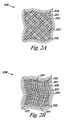
- Figs. 2A-2D illustrate embodiments for a variety of configurations for the cover 208.
- the embodiments illustrated in Figs. 2A-2D are segment views (i.e., partial views) used to provide a non-limiting illustration of different configurations of the matrix 222 and the flexible support members 224 used in the cover 208.
- Fig. 2A illustrates an embodiment in which the matrix 122 includes a first layer 201 and a second layer 203 of material positioned around the flexible support members 224.
- the flexible support members 224 have a knit configuration.
- Fig. 2B illustrates an embodiment in which the matrix 222 includes the first layer 201 and the second layer 203 of material positioned around a first course 205 of the flexible support members 224.
- the embodiment illustrated in Fig. 2B further includes a second course 207 of the flexible support members 224 positioned between the second layer 203 and a third layer 209 of the matrix 222.
- the first course 205 and the second course 207 of the flexible support members 224 in Fig. 2b have a woven configuration.
- different configurations of the flexible support members 224 e.g., one flexible support member course having a knit configuration and one flexible support member course having a coil configuration
- Fig. 2C illustrates another example of the cover 208 that includes the matrix 222 surrounding the flexible support members 224 in a continuous helically wound coil configuration.
- the layers of the matrix 122 material can have all, some or none of the layers of the same or chemical composition.
- the flexible support members 224 can have same or different configuration and/or chemical composition.
- mechanical properties of the cover 208 can be altered by changing the density, form, and/or texture of the flexible support members 224.
- Fig. 2D illustrates another example of the cover 208 that includes the matrix 222 that includes a distribution of the flexible support members 224.
- the distribution of the flexible support members 224 can include a distribution of the nanostructures (e.g., basalt, and/or carbon nanotubules), as discussed herein.
- the layers of the matrix 122 material can have all, some or none of the layers of the same or chemical composition.
- the flexible support members 224 can have same or different configuration and/or chemical composition.
- mechanical properties of the cover 208 can be altered by changing the density, form, and/or texture of the flexible support members 224.
- the fibers used in the flexible support members 124 may be made using a variety of processes that provide fibers with the desired properties (such as modulus, tensile strength, elongation etc.).
- desired properties such as modulus, tensile strength, elongation etc.
- Those skilled in the art of fiber processing are well versed in the art of extrusion, paste extrusion and stretching, solution spinning, electrostatic spinning, along with other fiber processing techniques, which may be used to provide polymer based fibers.
- These fibers may be oriented or drawn using conventional process to provide the desired degree of modulus, strength, and elongation.
- a fiber orientation process is used to improve the properties of the reinforcing fibers.
- the fibers can be oriented using a variety of drawing technologies such as single, multiple or continuous drawing steps with or without heating zones and/or relaxation. Additionally, these fibers may be post treated with various annealing, scouring, coating or surface treatment steps.
- the cover 108 can be formed in any number of ways.
- the embodiments of the cover 108 can be made by injecting, pouring, casting, or otherwise placing the matrix 122 material (e.g., a polymer solution) into a mold set-up comprised of a mold and the flexible support members 124.
- the embodiments of the cover 108 can be made by blending, or mixing, the matrix 122 material (e.g., a polymer) with flexible support members 124 (e.g., the carbon nano-tubules, or fibrous Basalt) before or during the injecting, pouring, or casting process into the mold.
- the general processing steps include the selection of the materials from which the matrix 122 and the flexible support members 124 are made.
- the cover 108 can generally be formed by use of compression molding in the mold set-up under a dry inert environment (for example, under nitrogen and/or argon) or under vacuum, at high enough temperatures, pressures, and long enough residence times (with proper cooling) to consolidate the composite.
- the cover 108 composite can be formed by use of an autoclave, under a dry inert environment or under vacuum, at high enough temperatures and long enough residence times to consolidate the composite.
- Proper consolidation condition should provide a composite with no voids therein.
- the flexible support members 124 are generally ceramic and/or polymeric (e.g., semi-crystalline polymers) while the matrix 122 materials are generally either amorphous or semi-crystalline polymers. In conventional composites, such as glass or carbon reinforced composites, the flexible support members 124 are not affected by consolidation temperature of the matrix 122. In addition, some or all of the fibers of the flexible support members 124 can be restrained during the consolidation process. The flexible support members 124 can be restrained during the heat treatment or the consolidation in a variety of ways, including, but not limited to, mechanical clamps or rack systems. This allows a reduction or a minimization in relaxation of fiber orientation. Additionally restraining the flexible support members 124 will control or avoid shrinkage of the flexible support members 124 during heat treatment and/or consolidation.
- the matrix 122 material can be extruded or formed into a tubing of appropriate size and thickness.
- the material of the matrix 122 can then be cross-linked to raise the melt temperature of the resulting tube.
- the tube can then inflated and stretched to give the includes a polymer a specific molecular orientation.
- the tube of the matrix 122 material can then be placed over the combination of an inner layer of the matrix 122 material and the flexible support members 124 and the material of the matrix 122 heat-shrunk around the flexible support members 124.
- the flexible support members 124 can be dipped into molten material of the matrix 122 to form the cover 108.
- suitable adhesive for the selected materials can be used to bond the matrix 122 material to additional layers of the matrix 122 material and to layers of the flexible support members 124.
- the matrix 122 can be co-processed with the flexible support members 124 (e.g., nanostructures or fibrous basalt) so as to distribute the flexible support members 124 through the matrix 122.
- the frame 102 too can be formed from a wide variety of materials and in a wide variety of configurations.
- frame 102 can have a unitary structure with an open frame configuration.
- the open frame configuration can include frame members 126 that define openings 128 across the frame 102 through which valve leaflets 104 and 106 formed by the cover 108 can radially-collapse and radially-expand, as will be described herein.
- first end 112 and the second end 114 each include a plurality of end portions 130 that lay on a common plane.
- the plurality of end portions 130 need not all lay on the common plane. In other words, it is possible that one or more of the end portions 130 of the frame 102 lay above and/or below the common plane.
- frames illustrated herein for example frame 102
- frame 102 are shown as having a circular configuration, other configurations are also possible.
- the frame 102 could have an elliptical configuration.
- the present invention should not be limited to the illustration of the frames, such as frame 102, provided herein.
- the frame 102 can further include a first leaflet connection region 132 and a second leaflet connection region 134 adjacent the second end 114 of the frame 102.
- the cover 108 can be coupled, as described more fully herein, to at least the first leaflet connection region 132 and the second leaflet connection region 134.
- the cover 108 so coupled can then move (e.g., pivot) relative the first leaflet connection region 132 and the second leaflet connection region 134 between an open valve configuration (illustrated in Figs. 1A and 1C ) and a closed valve configuration (illustrated in Figs. 1B and 1D ).
- the open frame configuration of frame 102 allows cover 108 to move through the openings 128 in creating the reversible sealable opening 120 of the valve 100.
- first leaflet connection region 132 and the second leaflet connection region 134 can be positioned opposite each other along a common axis.
- first leaflet connection region 132 and the second leaflet connection region 134 can be radially symmetric around a longitudinal central axis 138 of the frame 102.
- first leaflet connection region 132 and the second leaflet connection region 134 can be positioned approximately one hundred eighty (180) degrees relative each other around the longitudinal central axis 138 of the frame 102.
- the first leaflet connection region 132 and the second leaflet connection region 134 need not necessarily display an equally spaced symmetrical relationship as described above in order to practice the embodiments of the present invention.
- the radial relationship can have the first leaflet connection region 132 and the second leaflet connection region 134 positioned at values greater than one hundred eighty (180) degrees and less than one hundred eighty (180) degrees relative each other around the longitudinal central axis 138 of the frame 102.
- the frame 102 can have similar and/or different cross-sectional geometries along its length. The similarity and/or the differences in the cross-sectional geometries can be based on one or more desired functions to be elicited from each portion of the frame 102.
- the frame 102 can have a similar cross-sectional geometry along its length.
- cross-sectional geometries include, but are not limited to, round (e.g., circular, oval, and/or elliptical), rectangular geometries having perpendicular sides, one or more convex sides, or one or more concave sides; semi-circular; triangular; tubular; I-shaped; T-shaped; and trapezoidal. These embodiments, however, are not limited to the present examples as other cross-sectional geometries are also possible. As such, the present invention should not be limited to the frames provided in the illustration herein.
- the valve 100 can further include a radial support member 140.
- the radial support member 140 can include a number of different configurations, as will be described herein.
- the radial support member 140 couples the first leaflet connection region 132 and the second leaflet connection region 134.
- the radial support member 140 can also serve to stabilize the relative positions of the connection regions 132 and 134 (e.g., limit relative fluctuations of the connection regions 132 and 134).
- the radial support member 140 can be in the form of a tubular ring 142 that joins to the first leaflet connection region 132 and the second leaflet connection region 134.
- the valve 100 can further include a second tubular ring 144 located at the first end 112 of the frame 102.
- the tubular rings 142 and 144 can also move radially as the valve 100 radially collapses and expands.
- the valve 100 could further include additional tubular rings located at one or more positions along the frame 102.
- the radial support member can be provided to the frame 102 of the valve 100 due in part to dimensional relationships imparted to the frame 102.
- the cover 108 can be positioned over one or both of the radial support member 140 and the second tubular ring 144. As will be appreciated, the cover 108 need not extend to cover one or both of the radial support member 140 and the second tubular ring 144.
- the compressible nature of the valve 100 can accommodate changes in body lumen size (e.g., diameter of the body lumen) by flexing to expand and/or contract to change the diameter of the frame 102.
- the corner portions of the tubular rings 142 and 144, and the first leaflet connection region 132 and the second leaflet connection region 134 can act as springs to allow the valve 100 to resiliently radially collapse and expand.
- the frame 102 can also provide sufficient contact and expansion force with the surface of a body lumen wall to encourage fixation of the valve 100 and to prevent retrograde flow within the body lumen around the edges of the frame 102 and the surface of a lumen when combined with a closed state of the valve leaflets (described in more detail below) attached thereto.
- Anchoring elements e.g., barbs
- valve 100 can also be included with valve 100, as will be discussed herein.
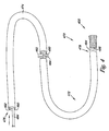
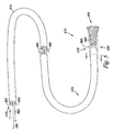
- Figs. 3A and 3B provide an example of the valve 300 in a collapsed state ( Fig. 3A ) and in an expanded state ( Fig. 3B ).
- the valve 300 can travel between the collapsed and the expanded state along a radial travel path 346 (as shown in Fig. 3B ), where there can be a change in a cross sectional area 348 of lumen 310.
- the frame 302 can travel along the radial travel path 346 so as to change a width 350 of lumen 310. This can allow the valve 300 to react appropriately to the distension and contraction of a body lumen in which the valve 300 is placed.
- Figs. 3A and 3B also provide an illustration of the valve 300 having a different configuration for the radial support members.
- the embodiments of the frame discussed herein can also be constructed of one or more of a number of materials and in a variety of configurations.
- the frame embodiments can have a unitary structure with an open frame configuration.
- the frame can also be self-expanding.
- self-expanding frames include those formed from temperature-sensitive memory alloy (e.g., Nitinol) which changes shape at a designated temperature or temperature range.
- the self-expanding frames can include those having a spring-bias.
- the frame 102 can have a configuration that allows the frame embodiments be radially expandable through the use of a balloon catheter.
- the embodiments of the frame can also be formed from one or more contiguous frame members.
- the frame member of frame embodiments can be a single contiguous member.
- the single contiguous member can be bent around an elongate tubular mandrel to form the frame.
- the free ends of the single contiguous member can then be welded, fused, crimped, or otherwise joined together to form the frame.
- the frame member of frame can be derived (e.g., laser cut, water cut) from a single tubular segment.
- methods of joining the frame member to create the elastic region include, but are not limited to, welding, gluing, and fusing the frame member.
- the frame can be heat set by a method as is typically known for the material which forms the frame.
- the frame embodiments can be formed from a number of materials.
- the frame can be formed from a biocompatible metal, metal alloy, polymeric material, or combination thereof.
- the frame can be self-expanding or balloon expandable.
- the frame can be configured so as to have the ability to move radially between the collapsed state and the expanded state.
- the material used to form the frame should exhibit a low elastic modulus and a high yield stress for large elastic strains that can recover from elastic deformations.
- suitable materials include, but are not limited to, medical grade stainless steel (e.g., 316L), titanium, tantalum, platinum alloys, niobium alloys, cobalt alloys, alginate, or combinations thereof.
- Additional frame embodiments may be formed from a shape-memory material, such as shape memory plastics, polymers, and thermoplastic materials which are inert in the body.
- shape memory alloys having superelastic properties generally made from ratios of nickel and titanium, commonly known as Nitinol, are also possible materials. Other materials are also possible.
- the lumen 110 can include a number of sizes.
- the size of the lumen can be determined based upon the type of body lumen and the body lumen size in which the valve is to be placed.
- the diameter can range from 4 mm to 20 mm. Other diameter values are also possible.
- the frame can further include one or more anchoring elements.
- the one or more anchoring elements can include, but are not limited to, one or more barbs 152 projecting from the frame 102.
- the valve can further include one or more radiopaque markers (e.g., tabs, sleeves, welds).
- one or more portions of the frame can be formed from a radiopaque material.
- Radiopaque markers can be attached to and/or coated onto one or more locations along the frame. Examples of radiopaque material include, but are not limited to, gold, tantalum, and platinum.
- the position of the one or more radiopaque markers can be selected so as to provide information on the position, location and orientation of the valve during its implantation.
- valve 100 further includes cover 108 having surfaces defining the reversibly sealable opening 120 for unidirectional flow of a liquid through the lumen 110.
- the cover 108 extends over at least a portion of the frame 102 to the first leaflet connection region 132 and the second leaflet connection region 134.
- the cover 108 extends between the first leaflet connection region 132 and the second leaflet connection region 134 to provide the first valve leaflet 104 and the second valve leaflet 106 of the valve leaflets.
- the first valve leaflet 104 and the second valve leaflet 106 include surfaces defining the reversibly sealable opening 120 extending between the first leaflet connection region 132 and the second leaflet connection region 134 for unidirectional flow of a liquid through the valve 100.
- valve leaflets 104 and 106 include a region 154 of the cover 108 that can move relative the frame 102.
- the region 154 of the cover 108 can be unbound (i.e., unsupported) by the frame 102 and extends between the first leaflet connection region 132 and the second leaflet connection region 134 of the valve 100.
- This configuration permits the reversibly sealable opening 120 to open and close in response to the fluid pressure differential across the valve leaflets 104 and 106.
- valve leaflets 104 and 106 can expand toward the inner surface 118 of the frame 102 to create an opening through which fluid is permitted to move.
- valve leaflets 104 and 106 each expand to define a semi-tubular structure when fluid opens the reversibly sealable opening 120.
- An example of the open configuration for the valve is shown in Figs. 1A and 1C .
- valve leaflets Under a retrograde fluid flow from the second end 114 towards the first end 112, the valve leaflets can move relative the inner surface 118 as the valve leaflets begin to close.
- a pocket exists between the frame 102 and each of the valve leaflets. The pocket allows fluid from the retrograde flow to develop a lower pressure on a first major face 155 of the valve leaflets than on the second major face 157 of the valve leaflets causing the valve leaflets to begin to close.
- fluid pressure develops on the pocket regions formed on the second major face 157, the valve leaflets collapse, closing the reversibly sealable opening 120, thereby restricting retrograde fluid flow through the valve 100.
- the valve leaflets can each have a concave structure when fluid closes the reversibly sealable opening 120.
- the concave structure can be imparted to the valve leaflets due to the configuration of the flexible support members 124 and/or the matrix 122.
- An example of the closed configuration for the valve is shown in Figs. 1B and 1D .
- Valve 100 provides an embodiment in which the surfaces defining the reversibly sealable opening 120 provide a bi-leaflet configuration (i.e., a bicuspid valve) for valve 100.
- a bi-leaflet configuration i.e., a bicuspid valve
- FIGS 1A-1D illustrate and describe a bi-leaflet configuration for the valve of the present invention
- designs employing a different number of valve leaflets e.g., tri-leaflet valve
- additional connection points e.g., three or more
- additional valve leaflets e.g., a tri-leaflet valve.
- the valve leaflets can have a variety of sizes and shapes. For example, each of the valve leaflets can have a similar size and shape. Alternatively, each of the valve leaflets need not have a similar size and shape (i.e., the valve leaflets can have a different size and shape with respect to each other). In addition, each of the valve leaflets include sufficient excess material spanning frame 102 such that fluid pressure (e.g., antegrade flow) acting on the region 154 of the valve leaflets forces the valve 100 into an open configuration ( Figs. 1 A and 1C ).
- the valve leaflets further include arcuate edges 156 that are positioned adjacent each other along a substantially catenary curve between the leaflet connection regions 132 and 134 in the closed configuration ( Figs. 1B and 1D ) of valve 100. Similarly, arcuate edges 156 can define opening 120 when the valve 100 is in the open configuration ( Figs. 1A and 1C ).
- arcuate edges 156 of valve 100 can open to approximately the full inner diameter of a body lumen.
- the arcuate edges 156 of valve 100 can open to approximately a diameter that is less than the full inner of a body lumen.
- Figs. 1A and 1C provide an illustration of this latter embodiment, where a space 163 can be present between the second major face 157 of the valve leaflets and the inner surface 118 of the frame 102.
- Each of the regions 154 of the valve leaflets can further include a concave structure that allows the valve leaflets to better collect retrograde fluid flow to urge the valve leaflets towards the closed configuration. For example, as retrograde flow begins, the valve leaflets respond by moving towards the center of valve 100. As the valve leaflets approach the center of the leaflets make sufficient contact to effectively close valve 100 and restrict retrograde fluid flow.
- the cover 108 can be located over at least the outer surface 116 and the inner surface 118 of the frame 102 to form the valve leaflets 104 and 106 as described herein.
- the cover 108 can be located over the inner surface 118 of the frame 102, or the cover 108 can be located over the outer surface 116 of the frame 102 to form the valve leaflets 104 and 106 as described herein.
- Numerous techniques may be employed to laminate or bond cover 108 on the outer surface 116 and/or the inner surface 118 of the frame 102, including heat setting, adhesive welding, application of uniform force and other bonding techniques.
- cover 108 may be folded over the first end 112 of the frame 102 to provide the cover 108 on both the outer surface 116 and the inner surface 118.
- Cover 108 can also be joined to itself and/or the members 126 according to the methods described in U. S. Patent Application Publication US 2002/0178570 to Sogard et al..
- the cover 108 can also be coupled to the connection regions so as to form the valve leaflets, as discussed herein.
- the cover 108 can be in the form of a sheet or a sleeve of material, as discussed herein, which can be connected to the frame 102.
- Other forms, including intermediate forms, of the cover 108 are also possible.
- the cover 108 can be coupled to the frame 102, including the connection regions 132 and 134, in a variety of ways so as to provide the various embodiments of the valve of the present invention.
- a variety of fasteners can be used to couple the cover 108 to the frame 102 so as to form the valve 100.
- Suitable fasteners can include, but are not limited to, biocompatible staples, glues, sutures or combinations thereof.
- the cover 108 can be coupled to the frame 102 through the use of heat sealing, solvent bonding, adhesive bonding, or welding cover 108 to either a portion of the cover 108 (i.e., itself) and/or the frame 102.
- the cover 108 including the valve leaflets 104 and 106, may also be treated and/or coated with any number of surface or material treatments.
- suitable bioactive agents which may be incorporated with or utilized together with embodiments of the present invention may include silver antimicrobial agents, metallic antimicrobial materials, growth factors, cellular migration agents, cellular proliferation agents, anti-coagulant substances, stenosis inhibitors, thrombo-resistant agents, antibiotic agents, anti-tumor agents, anti-proliferative agents, growth hormones, antiviral agents, anti- angiogenic agents, angiogenic agents, cholesterol-lowering agents, vasodilating agents, agents that interfere with endogenous vasoactive mechanisms, hormones, their homologs, derivatives, fragments, phannaceutical salts and combinations thereof.
- the most useful bioactive agents can include those that modulate thrombosis, those that encourage cellular ingrowth, throughgrowth, and endothelialization, those that resist infection, and those that reduce calcification.
- the cover 108 can be treated with one or more biologically active compounds and/or materials that may promote and/or inhibit endothelial, smooth muscle, fibroblast, and/or other cellular growth onto or into the cover 108, including the valve leaflets.
- the cover 108 may be seeded and covered with cultured tissue cells (e.g., endothelial cells) derived from a either a donor or the host patient which are attached to the valve leaflets. The cultured tissue cells may be initially positioned to extend either partially or fully over the valve leaflets.
- Cover 108 in addition to forming valve leaflets 104 and 106, can also be capable of inhibiting thrombus formation, as discussed herein. Additionally, cover 108 may either prevent or facilitate tissue ingrowth therethrough, as the particular application for the valve 100 may dictate. For example, cover 108 on the outer surface 116 may be formed from a porous material to facilitate tissue ingrowth therethrough, while cover 108 on the inner surface 118 may be formed from a material or a treated material which inhibits tissue ingrowth.
- Cells can be associated with the present invention.
- cells that have been genetically engineered to deliver bioactive proteins, such as the above mentioned growth factors or antibodies, to the implant site can be associated with the present invention.
- Cells can be of human origin (autologous or allogenic) or from an animal source (xenogenic).
- Cells can be pre-treated with medication or pre-processed such as by sorting or encapsulation.
- the delivery media can be formulated as needed to maintain cell function and viability.
- Thrombo-resistant agents associated with the present invention can include, but are not limited to, the following: heparin, heparin sulfate, hirudin, hyaluronic acid, chondroitin sulfate, dermatin sulfate, keratin sulfate, PPack (detropyenylalanine praline arginine chloromethylketone), lytic agents, including urokinase and streptokinase, their homologs, analogs, fragments, derivatives and pharmaceutical salts thereof.
- Anti-coagulants can include, but are not limited to, the following: D-Phe-Pro-Arg chloromethyl ketone, an RGD peptide-containing compound, heparain, antithrombin compounds, platelet receptor antagonists, anti-thrombin antibodies, anti-platelet receptor antibodies, aspirin, prostaglandin inhibitors, platelet inhibitors, tick antiplatelet peptides and combinations thereof.
- Antibiotic agents can include, but are not limited to, the following agents,: penicillins, cephalosportins, vancomycins, aminoglycosides, quinolonges, polymyxins, erythromycins, tetracyclines, chloraphenicols, clindamycins, lincomycins, sulfonamides, their homologs, analogs, derivatives, pharmaceutical salts and combinations thereof.
- Anti-proliferative agents for use in the present invention can include, but are not limited to, the following: paclitaxel, sirolimus, everolimus, or monoclonal antibodies capable of blocking smooth muscle cell proliferation, related compounds, derivatives, and combinations thereof.
- Vascular cell growth inhibitors can include, but are not limited to, the following: growth factor inhibitors, growth factor receptor antagonists, transcriptional repressors, translational repressors, replication inhibitors, inhibitory antibodies, antibodies directed against growth factors, bifunctional molecules consisting of a growth factor and a cytotoxin, bifunctional molecules consisting of a an antibody and a cytotoxin.
- Vascular cell growth promoters can include, but are not limited to, transcriptional activators and transcriptional promoters.
- anti-inflammatory agents can include, but are not limited to, the following: dexametbasone, prednisolone, corticosterone, budesonide, estrogen, sulfasalazinemesalamne, and combinations thereof.
- Fig. 4 illustrates one example of a system 470.
- System 470 includes valve 400, as described herein, reversibly joined to catheter 472.
- the catheter 472 includes an elongate body 474 having a proximal end 476 and a distal end 478, where valve 400 can be located between the proximal end 476 and distal end 478.
- the catheter 472 can further include a lumen 480 longitudinally extending to the distal end 478. In one example, lumen 480 extends between proximal end 476 and distal end 478 of catheter 472.
- the catheter 472 can further include a guidewire lumen 482 that extends within the elongate body 474, where the guidewire lumen 482 can receive a guidewire for positioning the catheter 472 and the valve 400 within a body lumen (e.g., a vein of a patient).
- a body lumen e.g., a vein of a patient.
- the system 470 can further include a deployment shaft 484 positioned within lumen 480, and a sheath 486 positioned adjacent the distal end 478.
- the valve 400 can be positioned at least partially within the sheath 486 and adjacent the deployment shaft 484.
- the deployment shaft 484 can be moved within the lumen 478 to deploy valve 400.
- deployment shaft 484 can be used to push valve 400 from sheath 486 in deploying valve 400.
- Fig. 5 illustrates an additional example of the system 570.
- the catheter 572 includes elongate body 574, lumen 580, a retraction system 588 and a retractable sheath 590.
- the retractable sheath 590 can be positioned over at least a portion of the elongate body 574, where the retractable sheath 590 can move longitudinally along the elongate body 574.
- the valve 500 can be positioned at least partially within the retractable sheath 590, where the retractable sheath 590 moves along the elongate body 574 to deploy the valve 500.
- retraction system 588 includes one or more wires 592 coupled to the retractable sheath 590, where the wires are positioned at least partially within and extend through lumen 580 in the elongate body 574. Wires of the retraction system 588 can then be used to retract the retractable sheath 590 in deploying valve 500.
- Fig. 6 illustrates an additional example of the system 670.
- the catheter 672 includes elongate body 674, an inflatable balloon 694 positioned adjacent the distal end 678, and a lumen 680 longitudinally extending in the elongate body 674 of the catheter 672 from the inflatable balloon 694 to the proximal end 676.
- the inflatable balloon 694 can be at least partially positioned within the lumen 606 of the valve 600.
- the inflatable balloon 694 can be inflated through the lumen 680 to deploy the valve 600.
- the embodiments of the present invention further include methods for forming the valve of the present invention, as discussed herein.
- the method of forming the valve includes forming the frame having the leaflet connection regions, as described.
- the method can include providing the radial support member, or members, on the frame for the leaflet connection regions.
- the radial support member can include the tubular rings adjacent the leaflet connection regions.
- the method also includes providing the cover on the frame, where connecting the cover to the leaflet connection regions provides at least the first leaflet and the second leaflet of the valve having surfaces defining the reversibly sealable opening for unidirectional flow of a liquid through the valve.
- the valve can be reversibly joined to the catheter, which can include a process of altering the shape of the valve from a first shape, for example an expanded state, to the compressed state, as described herein.
- the valve can be reversibly joined with the catheter by positioning valve in the compressed state at least partially within the sheath of the catheter.
- positioning the valve at least partially within the sheath of the catheter includes positioning the valve in the compressed state adjacent the deployment shaft of the catheter.
- the sheath of the catheter functions as a retractable sheath, where the valve in the compressed state can be reversibly joined with the catheter by positioning the valve at least partially within the reversible sheath of the catheter.
- the catheter can include an inflatable balloon, where the balloon can be positioned at least partially within the lumen of the valve, for example, in its compressed state.
- inventions of the valve described herein may be used to replace, supplement, or augment valve structures within one or more lumens of the body.
- embodiments of the present invention may be used to replace an incompetent venous valve and help to decrease backflow of blood in the venous system of the legs.
- the method of replacing, supplementing, and/or augmenting a valve structure can include positioning at least part of the catheter including the valve at a predetermined location within the lumen of a body.
- the predetermined location can include a position within a body lumen of a venous system of a patient, such as a vein of a leg.
- Positioning the catheter that includes the valve within the body lumen of a venous system includes introducing the catheter into the venous system of the patient using minimally invasive percutaneous, transluminal catheter based delivery system, as is known in the art.
- a guidewire can be positioned within a body lumen of a patient that includes the predetermined location.
- the catheter, including valve, as described herein can be positioned over the guidewire and the catheter advanced so as to position the valve at or adjacent the predetermined location.
- Radiopaque markers on the catheter and/or the valve, as described herein can be used to help locate and position the valve.
- the valve can be deployed from the catheter at the predetermined location in a number of ways, as described herein.
- the valve of the present invention can be deployed and placed in a number of vascular locations.
- the valve can be deployed and placed within a major vein of a patient's leg.
- Major veins include, but are not limited to, those of the peripheral venous system.
- veins in the peripheral venous system include, but are not limited to, the superficial veins such as the short saphenous vein and the greater saphenous vein, and the veins of the deep venous system, such as the popliteal vein and the femoral vein.
- the valve can be deployed from the catheter in a number of ways.
- the catheter can include the retractable sheath in which valve can be at least partially housed, as discussed herein.
- Valve can be deployed by retracting the retractable sheath of the catheter, where the valve self-expands to be positioned at the predetermined location.
- the catheter can include a deployment shaft and sheath in which valve can be at least partially housed adjacent the deployment shaft, as discussed herein.
- Valve a can be deployed by moving the deployment shaft through the catheter to deploy valve from the sheath, where the valve self-expands to be positioned at the predetermined location.
- the valve can be deployed through the use of an inflatable balloon.
- the valve can provide sufficient contact and expansion force against the body lumen wall to prevent retrograde flow between the valve and the body lumen wall.
- the valve can be selected to have a larger expansion diameter than the diameter of the inner wall of the body lumen. This can then allow valve to exert a force on the body lumen wall and accommodate changes in the body lumen diameter, while maintaining the proper placement of valve.
- the valve can engage the lumen so as to reduce the volume of retrograde flow through and around valve. It is, however, understood that some leaking or fluid flow may occur between the valve and the body lumen and/or through valve leaflets.
- both the radial support member and/or the support frame region of the valve can provide a self centering aspect to valve within a body lumen.
- the self centering aspect resulting from the radial support member and/or the support frame region may allow valve to maintain a substantially coaxial alignment with the body lumen (e.g., such as a vein) as valve leaflets deflect between the open and closed configurations so as to better seal the reversible opening when valve is closed.
- the frame 102 and/or the cover 108 can be coated with a non-thrombogenic biocompatible material, as are known or will be known.
Description
- The present invention relates generally to systems for use in a lumen and methods of forming a valve; and more particularly to valve systems for use in the vasculature system and methods of forming such valve systems.
- The venous system of the legs uses valves and muscles as part of the body's pumping mechanism to return blood to the heart. Venous valves create one way flow to prevent blood from flowing away from the heart. When valves fail, blood can pool in the lower legs resulting in swelling and ulcers of the leg. The absence of functioning venous valves can lead to chronic venous insufficiency.
- Techniques for both repairing and replacing the valves exist, but are tedious and require invasive surgical procedures. Direct and indirect valvuoplasty procedures are used to repair damaged valves. Transposition and transplantation are used to replace an incompetent valve. Transposition involves moving a vein with an incompetent valve to a site with a competent valve. Transplantation replaces an incompetent valve with a harvested valve from another venous site. Prosthetic valves can be transplanted into the venous system, but current devices are not successful enough to see widespread usage.
- Various examples of prosthetic valves exist. These can include those illustrated in the following patents and patent application:
US 2004/019374 andUS 2003/014104 . -
Figs. 1A-1B illustrate an embodiment of a valve. -
Fig. 1C illustrates a cross-sectional view of the valve illustrated inFig. 1A taken alongplane 1C-1C. -
Fig. 1D illustrates a cross-sectional view of the valve illustrated inFig. 1B taken alongplane 1D-1D. -
Figs. 2A-2D illustrate segment views of embodiments of a cover. -
Figs. 3A-3B illustrate a valve in an expanded and a collapsed state. -
Fig. 4 illustrates an embodiment of a system that includes a valve. -
Fig. 5 illustrates an embodiment of a system that includes a valve. -
Fig. 6 illustrates an embodiment of a system that includes a valve. - The present invention is defined by the features of the claims. Embodiments of the present invention are directed to a valve system for valve replacement or augmentation and to a method of forming a valve. The system includes a valve that can be used to replace or augment an incompetent valve in a body lumen. Embodiments of the valve include a frame and cover that can be implanted through minimally-invasive techniques into the body lumen. In one example, embodiments of the system and method for valve replacement or augmentation may help to maintain antegrade blood flow, while decreasing retrograde blood flow in a venous system of individuals having venous insufficiency, such as venous insufficiency in the legs.
- The figures herein follow a numbering convention in which the first digit or digits correspond to the drawing figure number and the remaining digits identify an element or component in the drawing. Similar elements or components between different figures may be identified by the use of similar digits. For example, 110 may reference element "10" in
Fig. 1 , and a similar element may be referenced as 210 inFig. 2 . As will be appreciated, elements shown in the various embodiments herein can be added, exchanged, and/or eliminated so as to provide a number of additional embodiments of valve. In addition, discussion of features and/or attributes for an element with respect to one Fig. can also apply to the element shown in one or more additional Figs. -
Figs. 1A-1D and3A-3B provide illustrations of various embodiments of a valve system of the present invention. Generally, the valve can be implanted within the fluid passageway of a body lumen, such as for replacement or augmentation of a valve structure within the body lumen (e.g., a venous valve). In one embodiment, the valve of the present invention may be beneficial to regulate the flow of a bodily fluid through the body lumen in a single direction. -
Figs. 1A-1D illustrate one embodiment of a venous valve orvalve system 100. Venousvalve 100 includes aframe 102, afirst leaflet 104 and asecond leaflet 106 formed from acover 108, where theframe 102 and theleaflets frame 102 and theleaflets lumen 110 of thevalve 100. Thelumen 110 allows for, among other things, fluid (e.g., blood) to move through thevalve 100. - The
frame 102 also includes afirst end 112 and asecond end 114. Thefirst end 112 and thesecond end 114 define a length of theframe 102 and of thevalve 100. In one embodiment, the length ofvalve 100 can have a number of values. As will be appreciated, the length ofvalve 100 can be determined based upon the location into which thevalve 100 is to be implanted. In other words, the length of thevalve 100 can be patient specific. Examples of values for the length include 4 millimeters to 30 millimeters. - The
frame 102 further includes anouter surface 116 and aninner surface 118 opposite theouter surface 116. In one embodiment, thecover 108 can be located over at least a portion of theouter surface 116 of theframe 102. For example, thecover 108 can extend around a perimeter of theframe 102 so as to cover theouter surface 116 of theframe 102. In other words, thecover 108 can extend over theouter surface 116 of theframe 102 so as to limit, or eliminate, exposed portions of theouter surface 116 of theframe 102. In an additional embodiment, thecover 108 can be located over at least a portion of theinner surface 118 of theframe 102. A further embodiment includes thecover 108 located over at least a portion of theouter surface 116 and theinner surface 118. - The
leaflets sealable opening 120 for unidirectional flow of a liquid through thelumen 110 of thevalve 100. For example, the surfaces of theleaflets lumen 110 can be restricted and an open configuration in which fluid flow through thelumen 110 can be permitted. - The
cover 108 further includes a physical configuration that provides support to the shape and structure of theleaflets cover 108 that help to maintain a pre-implant shape and size of the leaflets of the valve. - The physical configuration that provides support to the
leaflets cover 108 includesmatrix 122 reinforced withflexible support members 124 to provide a composite structure for theleaflets flexible support members 124 can be integrated into thematrix 122 so as to help prevent deformation of the original size and shape of theleaflets flexible support members 124 can be oriented to provide circumferential support to the first leaflet and thesecond leaflet - In one embodiment, the
cover 108 can have a multi-layer configuration in which at least one layer of the integratedflexible support members 124 can be integrated and/or laminated between at least one layer of thematrix 122 material. For example, as illustrated inFigs. 1A-1D , thecover 108 includes one or more layers of theflexible support members 124 and one or more layers of thematrix 122 that contribute to enhanced mechanical and handling properties of thecover 108. As discussed herein, the layers of theflexible support members 124 can be positioned to lie in a number of different relationships to each other. For example, the layers of theflexible support members 124 can lie in coplanar relations to one another, where the layers can have a number of angular relations to one another (e.g.; orthogonal relation to each other). Other configurations are also possible. - As illustrated, the
leaflets flexible support members 124 are positioned within thematrix 122 material of theleaflets cover 108 is illustrated as having theflexible support members 124 disposed substantially in the center of a cross section of thematrix 122, it is understood that theflexible support members 124 can be disposed at a number of locations within thecover 108. - In addition, different combinations of materials (discussed herein) can be used for one or more of the
flexible support members 124 and/or thematrix 122 material. For example, theflexible support members 124 of the same structure and chemistry or different structures and chemistries can be overlaid on top of one another to and combined with thematrix 122 material to fabricate acover 108 having the desired mechanical strength and physical properties. In an additional embodiment, thecover 108 forming theleaflets matrix 122 can be formed of a first material and theflexible support members 124 can be formed of a second material different than the first material. For example, theleaflets matrix 122 of the first material and a bottom layer of thematrix 122 of first material coupled to the top layer of the first material. Theflexible support members 124 of theleaflets matrix 122 can be integrated with theflexible support members 124 in such a way that the material of thematrix 122 penetrates through openings between theflexible support members 124 to interlock thematrix 122 and theflexible support members 124. Surfaces of adjacent layers of thematrix 122 material can also interlock with one another, regardless of whether the layers of thematrix 122 are separated by a layer of theflexible support members 124 or whether they are made from the same or different materials. - In an additional embodiment, the
flexible support members 124 can include a number of forms that contribute to both the mechanical and handling properties of thecover 108. Theflexible support members 124 include a braids. - In addition, mechanical properties of the
cover 108 can be altered by changing the density, form, and/or texture of theflexible support members 124 in one or more locations of thecover 108. Examples of suitable structures used to create theflexible support members 124 can include, for example, monofilaments, yarns, threads, braids, or bundles of fibers. - Regardless of its configuration, the composite structure of the
cover 108 should possess a burst strength adequate to withstand pressures imposed by blood moving in the circulation system. In addition, thecover 108 can be sufficiently thin and pliable so as to permit radially-collapsing of theleaflets valve 100 to allow thevalve 100 to provide the reversiblysealable opening 120 and for delivery by catheter to a location within a body lumen. As discussed herein, different portions of thematrix 122 and/or theflexible support members 124 may be made from different materials. Adequate strength and physical properties are developed in thecover 108 through the selection of materials used to form thematrix 122 and theflexible support members 124, and the manufacturing process used to join them. - By way of example, both the
matrix 122 and theflexible support members 124 can be formed of a number of materials. For example, thematrix 122 and/or theflexible support members 124 can be formed of, by way of illustration and not by limitation, thermoplastic and thermo-set polymers. Examples of these polymers include polyolefins such as polyethylene and polypropylene, polyesters such as Dacron®, polyethylene terephthalate and polybutylene terephthalate, vinyl halide polymers such as polyvinyl chloride (PVC), polyvinylacetate such as ethyl vinyl acetate (EVA), polyurethanes, polymethylmethacrylate, pellethane, polyamides such as nylon 4, nylon 6, nylon 66, nylon 610, nylon 11, nylon 12 and polycaprolactam, polyaramids (e.g., KEVLAR), polystyrene-polyisobutylene-polystyrene (SIBS), segmented poly(carbonate-urethane), Rayon, fluoropolymers such as polytetrafluoroethylene (PTFE or TFE) or expanded polytetrafluoroethylene (ePTFE), ethylene-chlorofluoroethylene (ECTFE), fluorinated ethylene propylene (FEP), polychlorotrifluoroethylene (PCTFE), polyvinylfluoride (PVF), or polyvinylidenefluoride (PVDF), natural biopolymers such as cellulose, chitin, keratin, silk, and collagen, explanted veins, decellularized basement membrane materials, submucosa materials such as small intestine submucosa (SIS) or umbilical vein, or other naturally occurring extracellular matrix (ECM), and other autologous or allogeneic biological materials either treated by crosslinking or not, and mixtures and copolymers thereof. SIS and ECM materials can be autologous, allogeneic or xenograft material derived from mammals, including source, such as human, cattle, sheep, and porcine. As will be appreciated, blends or mixtures of two or more of the materials provided herein are possible. For example, SIBS can be blended with one or more basement membrane materials. - Each of the polymers noted herein may be used in conjunction with radioopaque filler materials such as barium sulfate, bismuth trioxide, bismuth carbonate, powdered tungsten, powdered tantalum, or the like so that the location of the
matrix 122 and/or theflexible support members 124 may be radiographically visualized within the human body. - In another example, the polymers and blends that are used to form the composite can be used as a drug delivery matrix. To form this matrix, the polymer can be mixed with a therapeutic agent or the agent can be applied to the surface or otherwise delivered from the material. The variety of different therapeutic agents that can be used in conjunction with the polymers of the present invention is vast. In general, therapeutic agents which may be administered via the pharmaceutical compositions of the invention include, without limitation: antiinfectives such as antibiotics and antiviral agents; analgesics and analgesic combinations; anti-inflammatory agents; hormones such as steroids; and naturally derived or genetically engineered proteins, polysaccharides, glycoproteins, or lipoproteins, anti-thrombotic agents, anti Pt agents, anti-immunogenic agents, anti-mitotic agents, anti proliferative agents, and angiogenic agents. Matrix formulations may be formulated by mixing one or more therapeutic agents with the polymer. The therapeutic agent may be present as a liquid, a finely divided solid, or any other appropriate physical form. Typically, but optionally, the matrix will include one or more additives, such as diluents, carriers, excipients, stabilizers or the like. Additionally, radioopaque markers may be added to the composite to allow imaging of the composite after implantation.
- In an additional example, the
flexible support members 124 can be formed of ceramics, and/or metals. Suitable ceramics for theflexible support members 124 include those formed from basalt (solidified volcanic lava), and sold under the trade identifier "Sudaglass." In one embodiment, the basalt can be mechanically crushed to provide the basalt in a fibrous form having a predetermined size of 9 to 17 microns in length. The basalt in the fibrous form can be blended with one or more of the polymers noted herein (e.g., SIBS, or polyolefins) so as to distribute the basalt in the fibrous form through the polymer matrix. In one example, the basalt polymer composite can include 0.1 percent (wt.) basalt in the fibrous form. As will be appreciated, other weight percentage of basalt in the fibrous form relative polymer are possible. - The
flexible support members 124 can also be formed of other nanostructures, such as carbon nanotubules. For example, carbon nano-tubules can be blended with one or more of the polymers noted herein (e.g., SIBS) so as to distribute the carbon nano-tubules through the polymer matrix. In one embodiment, the carbon nano-tubule polymer composite can include from 0.1 percent to 20 percent (wt.) carbon nano-tubules. As will be appreciated, other weight percentage of carbon nano-tubules relative polymer are possible. - The
flexible support members 124 can also be formed of metals and/or metal alloys. For example, suitable metals and/or metal alloys for theflexible support members 124 include, but are not limited to, medical grade stainless steels (304, 306, 308, 316L, 318, etc.), gold, platinum, platinum alloys, palladium, rhodium, tungsten, tungsten alloys, cobalt chrome, titanium and titanium alloys, and other metal alloys such as those composed of titanium/nickel and sold under the trade identifier "Nitinol." - Heat treatment of the Nitinol alloy may also be desirable. An example of such a heat treatment includes, but is not limited to, placing the Nitinol in its desired shape onto a mandrel. The Nitinol is then heated to a temperature of 650°-750° F. for a predetermined time (e.g., two (2) to five (5) minutes), possibly (but not necessarily) annealing the constituent Nitinol. After heat treatment, the
flexible support members 124 retain their shape and the Nitinol alloy retains its super-elastic properties. - The
support members 124 can also include a variety of cross-sectional configurations. For example, thesupport members 124 can have one or more of a round (e.g., circular, oval, and/or elliptical), "ribbon" configuration with rectangular geometries with an aspect ratio of at least 0.5 (thickness/width) having perpendicular sides, one or more convex sides, or one or more concave sides; semi-circular; triangular; tubular; I-shaped; T-shaped; and trapezoidal. Theses embodiment, however, are not limited to the present examples as other cross-sectional geometries are also possible. With respect to "braid," the term can include tubular constructions in which theflexible support members 124 making up the construction are woven radially in an in-and-out fashion as they cross to form a tubular member defining a single lumen. The braid can also be constructed offlexible support members 124 of different widths. Changes in the braid can allow for pocket formation and the shape of theleaflets -
Figs. 2A-2D illustrate embodiments for a variety of configurations for thecover 208. The embodiments illustrated inFigs. 2A-2D are segment views (i.e., partial views) used to provide a non-limiting illustration of different configurations of thematrix 222 and theflexible support members 224 used in thecover 208. For example,Fig. 2A illustrates an embodiment in which thematrix 122 includes afirst layer 201 and asecond layer 203 of material positioned around theflexible support members 224. As illustrated inFig. 2A , theflexible support members 224 have a knit configuration. - In an additional embodiment,
Fig. 2B illustrates an embodiment in which thematrix 222 includes thefirst layer 201 and thesecond layer 203 of material positioned around afirst course 205 of theflexible support members 224. The embodiment illustrated inFig. 2B further includes asecond course 207 of theflexible support members 224 positioned between thesecond layer 203 and athird layer 209 of thematrix 222. As illustrated, thefirst course 205 and thesecond course 207 of theflexible support members 224 inFig. 2b have a woven configuration. As will be appreciated, different configurations of the flexible support members 224 (e.g., one flexible support member course having a knit configuration and one flexible support member course having a coil configuration) could be combined in the cover 204. -
Fig. 2C illustrates another example of thecover 208 that includes thematrix 222 surrounding theflexible support members 224 in a continuous helically wound coil configuration. As will be appreciated, the layers of thematrix 122 material can have all, some or none of the layers of the same or chemical composition. Similarly, theflexible support members 224 can have same or different configuration and/or chemical composition. In addition, mechanical properties of thecover 208 can be altered by changing the density, form, and/or texture of theflexible support members 224. -
Fig. 2D illustrates another example of thecover 208 that includes thematrix 222 that includes a distribution of theflexible support members 224. In one embodiment, the distribution of theflexible support members 224 can include a distribution of the nanostructures (e.g., basalt, and/or carbon nanotubules), as discussed herein. As will be appreciated, the layers of thematrix 122 material can have all, some or none of the layers of the same or chemical composition. Similarly, theflexible support members 224 can have same or different configuration and/or chemical composition. In addition, mechanical properties of thecover 208 can be altered by changing the density, form, and/or texture of theflexible support members 224. - Referring again to
Figs. 1A-1D , the fibers used in theflexible support members 124 may be made using a variety of processes that provide fibers with the desired properties (such as modulus, tensile strength, elongation etc.). Those skilled in the art of fiber processing are well versed in the art of extrusion, paste extrusion and stretching, solution spinning, electrostatic spinning, along with other fiber processing techniques, which may be used to provide polymer based fibers. These fibers may be oriented or drawn using conventional process to provide the desired degree of modulus, strength, and elongation. Generally, a fiber orientation process is used to improve the properties of the reinforcing fibers. The fibers can be oriented using a variety of drawing technologies such as single, multiple or continuous drawing steps with or without heating zones and/or relaxation. Additionally, these fibers may be post treated with various annealing, scouring, coating or surface treatment steps. - As will be appreciated, the
cover 108 can be formed in any number of ways. For example, the embodiments of thecover 108 can be made by injecting, pouring, casting, or otherwise placing thematrix 122 material (e.g., a polymer solution) into a mold set-up comprised of a mold and theflexible support members 124. Alternatively, the embodiments of thecover 108 can be made by blending, or mixing, thematrix 122 material (e.g., a polymer) with flexible support members 124 (e.g., the carbon nano-tubules, or fibrous Basalt) before or during the injecting, pouring, or casting process into the mold. - The general processing steps include the selection of the materials from which the
matrix 122 and theflexible support members 124 are made. In one embodiment, thecover 108 can generally be formed by use of compression molding in the mold set-up under a dry inert environment (for example, under nitrogen and/or argon) or under vacuum, at high enough temperatures, pressures, and long enough residence times (with proper cooling) to consolidate the composite. Alternately, thecover 108 composite can be formed by use of an autoclave, under a dry inert environment or under vacuum, at high enough temperatures and long enough residence times to consolidate the composite. Proper consolidation condition should provide a composite with no voids therein. - The
flexible support members 124 are generally ceramic and/or polymeric (e.g., semi-crystalline polymers) while thematrix 122 materials are generally either amorphous or semi-crystalline polymers. In conventional composites, such as glass or carbon reinforced composites, theflexible support members 124 are not affected by consolidation temperature of thematrix 122. In addition, some or all of the fibers of theflexible support members 124 can be restrained during the consolidation process. Theflexible support members 124 can be restrained during the heat treatment or the consolidation in a variety of ways, including, but not limited to, mechanical clamps or rack systems. This allows a reduction or a minimization in relaxation of fiber orientation. Additionally restraining theflexible support members 124 will control or avoid shrinkage of theflexible support members 124 during heat treatment and/or consolidation. - In an alternative embodiment, the
matrix 122 material can be extruded or formed into a tubing of appropriate size and thickness. The material of thematrix 122 can then be cross-linked to raise the melt temperature of the resulting tube. The tube can then inflated and stretched to give the includes a polymer a specific molecular orientation. The tube of thematrix 122 material can then be placed over the combination of an inner layer of thematrix 122 material and theflexible support members 124 and the material of thematrix 122 heat-shrunk around theflexible support members 124. Alternatively, theflexible support members 124 can be dipped into molten material of thematrix 122 to form thecover 108. In yet another embodiment, suitable adhesive for the selected materials can be used to bond thematrix 122 material to additional layers of thematrix 122 material and to layers of theflexible support members 124. In an additional embodiment, thematrix 122 can be co-processed with the flexible support members 124 (e.g., nanostructures or fibrous basalt) so as to distribute theflexible support members 124 through thematrix 122. - In addition to the
cover 108, theframe 102 too can be formed from a wide variety of materials and in a wide variety of configurations. Generally,frame 102 can have a unitary structure with an open frame configuration. For example, the open frame configuration can includeframe members 126 that defineopenings 128 across theframe 102 through whichvalve leaflets cover 108 can radially-collapse and radially-expand, as will be described herein. - In addition, the
first end 112 and thesecond end 114 each include a plurality ofend portions 130 that lay on a common plane. The plurality ofend portions 130, however, need not all lay on the common plane. In other words, it is possible that one or more of theend portions 130 of theframe 102 lay above and/or below the common plane. - While the frames illustrated herein, for
example frame 102, are shown as having a circular configuration, other configurations are also possible. For example, theframe 102 could have an elliptical configuration. As such, the present invention should not be limited to the illustration of the frames, such asframe 102, provided herein. - As illustrated in
Figs. 1A-1D , theframe 102 can further include a firstleaflet connection region 132 and a secondleaflet connection region 134 adjacent thesecond end 114 of theframe 102. In the present example, thecover 108 can be coupled, as described more fully herein, to at least the firstleaflet connection region 132 and the secondleaflet connection region 134. Thecover 108 so coupled can then move (e.g., pivot) relative the firstleaflet connection region 132 and the secondleaflet connection region 134 between an open valve configuration (illustrated inFigs. 1A and1C ) and a closed valve configuration (illustrated inFigs. 1B and1D ). As illustrated in the closed valve configuration (Figs. 1B and1D ), the open frame configuration offrame 102 allowscover 108 to move through theopenings 128 in creating the reversible sealable opening 120 of thevalve 100. - As illustrated in
Figs. 1A-1D , the firstleaflet connection region 132 and the secondleaflet connection region 134 can be positioned opposite each other along a common axis. In addition, the firstleaflet connection region 132 and the secondleaflet connection region 134 can be radially symmetric around a longitudinalcentral axis 138 of theframe 102. As illustrated, the firstleaflet connection region 132 and the secondleaflet connection region 134 can be positioned approximately one hundred eighty (180) degrees relative each other around the longitudinalcentral axis 138 of theframe 102. As will be appreciated, the firstleaflet connection region 132 and the secondleaflet connection region 134 need not necessarily display an equally spaced symmetrical relationship as described above in order to practice the embodiments of the present invention. For example, the radial relationship can have the firstleaflet connection region 132 and the secondleaflet connection region 134 positioned at values greater than one hundred eighty (180) degrees and less than one hundred eighty (180) degrees relative each other around the longitudinalcentral axis 138 of theframe 102. - The
frame 102 can have similar and/or different cross-sectional geometries along its length. The similarity and/or the differences in the cross-sectional geometries can be based on one or more desired functions to be elicited from each portion of theframe 102. For example, theframe 102 can have a similar cross-sectional geometry along its length. Examples of cross-sectional geometries include, but are not limited to, round (e.g., circular, oval, and/or elliptical), rectangular geometries having perpendicular sides, one or more convex sides, or one or more concave sides; semi-circular; triangular; tubular; I-shaped; T-shaped; and trapezoidal. These embodiments, however, are not limited to the present examples as other cross-sectional geometries are also possible. As such, the present invention should not be limited to the frames provided in the illustration herein. - The
valve 100 can further include aradial support member 140. Theradial support member 140 can include a number of different configurations, as will be described herein. For example, in the embodiment illustrated inFigs. 1A-1D , theradial support member 140 couples the firstleaflet connection region 132 and the secondleaflet connection region 134. In addition to coupling theconnection regions radial support member 140 can also serve to stabilize the relative positions of theconnection regions 132 and 134 (e.g., limit relative fluctuations of theconnection regions 132 and 134). - In the present example, the
radial support member 140 can be in the form of atubular ring 142 that joins to the firstleaflet connection region 132 and the secondleaflet connection region 134. Thevalve 100 can further include a secondtubular ring 144 located at thefirst end 112 of theframe 102. The tubular rings 142 and 144 can also move radially as thevalve 100 radially collapses and expands. As will be appreciated, thevalve 100 could further include additional tubular rings located at one or more positions along theframe 102. In an alternative example, the radial support member can be provided to theframe 102 of thevalve 100 due in part to dimensional relationships imparted to theframe 102. - As illustrated, the
cover 108 can be positioned over one or both of theradial support member 140 and the secondtubular ring 144. As will be appreciated, thecover 108 need not extend to cover one or both of theradial support member 140 and the secondtubular ring 144. - The compressible nature of the
valve 100 can accommodate changes in body lumen size (e.g., diameter of the body lumen) by flexing to expand and/or contract to change the diameter of theframe 102. In one embodiment, the corner portions of the tubular rings 142 and 144, and the firstleaflet connection region 132 and the secondleaflet connection region 134 can act as springs to allow thevalve 100 to resiliently radially collapse and expand. Theframe 102 can also provide sufficient contact and expansion force with the surface of a body lumen wall to encourage fixation of thevalve 100 and to prevent retrograde flow within the body lumen around the edges of theframe 102 and the surface of a lumen when combined with a closed state of the valve leaflets (described in more detail below) attached thereto. Anchoring elements (e.g., barbs) can also be included withvalve 100, as will be discussed herein. -
Figs. 3A and 3B provide an example of thevalve 300 in a collapsed state (Fig. 3A ) and in an expanded state (Fig. 3B ). As shown inFigs. 3A and 3B , thevalve 300 can travel between the collapsed and the expanded state along a radial travel path 346 (as shown inFig. 3B ), where there can be a change in a crosssectional area 348 oflumen 310. For example, theframe 302 can travel along theradial travel path 346 so as to change awidth 350 oflumen 310. This can allow thevalve 300 to react appropriately to the distension and contraction of a body lumen in which thevalve 300 is placed.Figs. 3A and 3B also provide an illustration of thevalve 300 having a different configuration for the radial support members. - The embodiments of the frame discussed herein can also be constructed of one or more of a number of materials and in a variety of configurations. Generally, the frame embodiments can have a unitary structure with an open frame configuration. The frame can also be self-expanding. Examples of self-expanding frames include those formed from temperature-sensitive memory alloy (e.g., Nitinol) which changes shape at a designated temperature or temperature range. Alternatively, the self-expanding frames can include those having a spring-bias. In addition, the
frame 102 can have a configuration that allows the frame embodiments be radially expandable through the use of a balloon catheter. - The embodiments of the frame, such as
frame 102 inFig. 1 , can also be formed from one or more contiguous frame members. For example, the frame member of frame embodiments can be a single contiguous member. The single contiguous member can be bent around an elongate tubular mandrel to form the frame. The free ends of the single contiguous member can then be welded, fused, crimped, or otherwise joined together to form the frame. In an additional embodiment, the frame member of frame can be derived (e.g., laser cut, water cut) from a single tubular segment. In an alternative embodiment, methods of joining the frame member to create the elastic region include, but are not limited to, welding, gluing, and fusing the frame member. The frame can be heat set by a method as is typically known for the material which forms the frame. - The frame embodiments can be formed from a number of materials. For example, the frame can be formed from a biocompatible metal, metal alloy, polymeric material, or combination thereof. As discussed herein, the frame can be self-expanding or balloon expandable. In addition, the frame can be configured so as to have the ability to move radially between the collapsed state and the expanded state. To accomplish this, the material used to form the frame should exhibit a low elastic modulus and a high yield stress for large elastic strains that can recover from elastic deformations. Examples of suitable materials include, but are not limited to, medical grade stainless steel (e.g., 316L), titanium, tantalum, platinum alloys, niobium alloys, cobalt alloys, alginate, or combinations thereof. Additional frame embodiments may be formed from a shape-memory material, such as shape memory plastics, polymers, and thermoplastic materials which are inert in the body. Shaped memory alloys having superelastic properties generally made from ratios of nickel and titanium, commonly known as Nitinol, are also possible materials. Other materials are also possible.
- The
lumen 110 can include a number of sizes. For example, the size of the lumen can be determined based upon the type of body lumen and the body lumen size in which the valve is to be placed. In an additional example, there can also be a minimum value for the width for the frame that ensures that the frame will have an appropriate expansion force against the inner wall of the body lumen in which the valve is being placed. For example, the diameter can range from 4 mm to 20 mm. Other diameter values are also possible. - In one example, the frame can further include one or more anchoring elements. For example, the one or more anchoring elements can include, but are not limited to, one or
more barbs 152 projecting from theframe 102. The valve can further include one or more radiopaque markers (e.g., tabs, sleeves, welds). For example, one or more portions of the frame can be formed from a radiopaque material. Radiopaque markers can be attached to and/or coated onto one or more locations along the frame. Examples of radiopaque material include, but are not limited to, gold, tantalum, and platinum. The position of the one or more radiopaque markers can be selected so as to provide information on the position, location and orientation of the valve during its implantation. - As discussed herein,
valve 100 further includescover 108 having surfaces defining the reversiblysealable opening 120 for unidirectional flow of a liquid through thelumen 110. For the embodiment illustrated inFigs. 1A-1D , thecover 108 extends over at least a portion of theframe 102 to the firstleaflet connection region 132 and the secondleaflet connection region 134. Thecover 108 extends between the firstleaflet connection region 132 and the secondleaflet connection region 134 to provide thefirst valve leaflet 104 and thesecond valve leaflet 106 of the valve leaflets. Thefirst valve leaflet 104 and thesecond valve leaflet 106 include surfaces defining the reversiblysealable opening 120 extending between the firstleaflet connection region 132 and the secondleaflet connection region 134 for unidirectional flow of a liquid through thevalve 100. - As illustrated, the
valve leaflets region 154 of thecover 108 that can move relative theframe 102. Theregion 154 of thecover 108 can be unbound (i.e., unsupported) by theframe 102 and extends between the firstleaflet connection region 132 and the secondleaflet connection region 134 of thevalve 100. This configuration permits the reversiblysealable opening 120 to open and close in response to the fluid pressure differential across thevalve leaflets - For example, under antegrade fluid flow (i.e., positive fluid pressure) from the
first end 112 towards thesecond end 114 of thevalve 100, thevalve leaflets inner surface 118 of theframe 102 to create an opening through which fluid is permitted to move. In one example, thevalve leaflets sealable opening 120. An example of the open configuration for the valve is shown inFigs. 1A and1C . - Under a retrograde fluid flow from the
second end 114 towards thefirst end 112, the valve leaflets can move relative theinner surface 118 as the valve leaflets begin to close. In one example, a pocket exists between theframe 102 and each of the valve leaflets. The pocket allows fluid from the retrograde flow to develop a lower pressure on a firstmajor face 155 of the valve leaflets than on the secondmajor face 157 of the valve leaflets causing the valve leaflets to begin to close. As fluid pressure develops on the pocket regions formed on the secondmajor face 157, the valve leaflets collapse, closing the reversiblysealable opening 120, thereby restricting retrograde fluid flow through thevalve 100. In the closed configuration, the valve leaflets can each have a concave structure when fluid closes the reversiblysealable opening 120. In one embodiment, the concave structure can be imparted to the valve leaflets due to the configuration of theflexible support members 124 and/or thematrix 122. An example of the closed configuration for the valve is shown inFigs. 1B and1D . -
Valve 100 provides an embodiment in which the surfaces defining the reversiblysealable opening 120 provide a bi-leaflet configuration (i.e., a bicuspid valve) forvalve 100. Although the embodiments inFigures 1A-1D illustrate and describe a bi-leaflet configuration for the valve of the present invention, designs employing a different number of valve leaflets (e.g., tri-leaflet valve) are possible. For example, additional connection points (e.g., three or more) could be used to provide additional valve leaflets (e.g., a tri-leaflet valve). - The valve leaflets can have a variety of sizes and shapes. For example, each of the valve leaflets can have a similar size and shape. Alternatively, each of the valve leaflets need not have a similar size and shape (i.e., the valve leaflets can have a different size and shape with respect to each other). In addition, each of the valve leaflets include sufficient excess
material spanning frame 102 such that fluid pressure (e.g., antegrade flow) acting on theregion 154 of the valve leaflets forces thevalve 100 into an open configuration (Figs. 1 A and 1C ). The valve leaflets further includearcuate edges 156 that are positioned adjacent each other along a substantially catenary curve between theleaflet connection regions Figs. 1B and1D ) ofvalve 100. Similarly,arcuate edges 156 can defineopening 120 when thevalve 100 is in the open configuration (Figs. 1A and1C ). - In an additional embodiment, in the open configuration the portion of the
cover 108 forming thevalve leaflets leaflet connection regions Fig. 1A , when fluid pressure opens thevalve 100. In an additional embodiment,arcuate edges 156 ofvalve 100 can open to approximately the full inner diameter of a body lumen. Alternatively, thearcuate edges 156 ofvalve 100 can open to approximately a diameter that is less than the full inner of a body lumen.Figs. 1A and1C provide an illustration of this latter embodiment, where aspace 163 can be present between the secondmajor face 157 of the valve leaflets and theinner surface 118 of theframe 102. - Each of the
regions 154 of the valve leaflets can further include a concave structure that allows the valve leaflets to better collect retrograde fluid flow to urge the valve leaflets towards the closed configuration. For example, as retrograde flow begins, the valve leaflets respond by moving towards the center ofvalve 100. As the valve leaflets approach the center of the leaflets make sufficient contact to effectivelyclose valve 100 and restrict retrograde fluid flow. - As discussed herein, the
cover 108 can be located over at least theouter surface 116 and theinner surface 118 of theframe 102 to form thevalve leaflets cover 108 can be located over theinner surface 118 of theframe 102, or thecover 108 can be located over theouter surface 116 of theframe 102 to form thevalve leaflets bond cover 108 on theouter surface 116 and/or theinner surface 118 of theframe 102, including heat setting, adhesive welding, application of uniform force and other bonding techniques. Additionally, thecover 108 may be folded over thefirst end 112 of theframe 102 to provide thecover 108 on both theouter surface 116 and theinner surface 118. Cover 108 can also be joined to itself and/or themembers 126 according to the methods described in U. S. Patent Application PublicationUS 2002/0178570 to Sogard et al.. - The
cover 108 can also be coupled to the connection regions so as to form the valve leaflets, as discussed herein. In one embodiment, thecover 108 can be in the form of a sheet or a sleeve of material, as discussed herein, which can be connected to theframe 102. Other forms, including intermediate forms, of thecover 108 are also possible. - The
cover 108 can be coupled to theframe 102, including theconnection regions cover 108 to theframe 102 so as to form thevalve 100. Suitable fasteners can include, but are not limited to, biocompatible staples, glues, sutures or combinations thereof. In an additional embodiment, thecover 108 can be coupled to theframe 102 through the use of heat sealing, solvent bonding, adhesive bonding, orwelding cover 108 to either a portion of the cover 108 (i.e., itself) and/or theframe 102. - The
cover 108, including thevalve leaflets - In the various embodiments of the present invention, the most useful bioactive agents can include those that modulate thrombosis, those that encourage cellular ingrowth, throughgrowth, and endothelialization, those that resist infection, and those that reduce calcification. For example, the
cover 108 can be treated with one or more biologically active compounds and/or materials that may promote and/or inhibit endothelial, smooth muscle, fibroblast, and/or other cellular growth onto or into thecover 108, including the valve leaflets. Similarly, thecover 108 may be seeded and covered with cultured tissue cells (e.g., endothelial cells) derived from a either a donor or the host patient which are attached to the valve leaflets. The cultured tissue cells may be initially positioned to extend either partially or fully over the valve leaflets. -
Cover 108, in addition to formingvalve leaflets valve 100 may dictate. For example, cover 108 on theouter surface 116 may be formed from a porous material to facilitate tissue ingrowth therethrough, whilecover 108 on theinner surface 118 may be formed from a material or a treated material which inhibits tissue ingrowth. - Cells can be associated with the present invention. For example, cells that have been genetically engineered to deliver bioactive proteins, such as the above mentioned growth factors or antibodies, to the implant site can be associated with the present invention. Cells can be of human origin (autologous or allogenic) or from an animal source (xenogenic). Cells can be pre-treated with medication or pre-processed such as by sorting or encapsulation. The delivery media can be formulated as needed to maintain cell function and viability.
- Thrombo-resistant agents associated with the present invention can include, but are not limited to, the following: heparin, heparin sulfate, hirudin, hyaluronic acid, chondroitin sulfate, dermatin sulfate, keratin sulfate, PPack (detropyenylalanine praline arginine chloromethylketone), lytic agents, including urokinase and streptokinase, their homologs, analogs, fragments, derivatives and pharmaceutical salts thereof.
- Anti-coagulants can include, but are not limited to, the following: D-Phe-Pro-Arg chloromethyl ketone, an RGD peptide-containing compound, heparain, antithrombin compounds, platelet receptor antagonists, anti-thrombin antibodies, anti-platelet receptor antibodies, aspirin, prostaglandin inhibitors, platelet inhibitors, tick antiplatelet peptides and combinations thereof.
- Antibiotic agents can include, but are not limited to, the following agents,: penicillins, cephalosportins, vancomycins, aminoglycosides, quinolonges, polymyxins, erythromycins, tetracyclines, chloraphenicols, clindamycins, lincomycins, sulfonamides, their homologs, analogs, derivatives, pharmaceutical salts and combinations thereof.
- Anti-proliferative agents for use in the present invention can include, but are not limited to, the following: paclitaxel, sirolimus, everolimus, or monoclonal antibodies capable of blocking smooth muscle cell proliferation, related compounds, derivatives, and combinations thereof.
- Vascular cell growth inhibitors can include, but are not limited to, the following: growth factor inhibitors, growth factor receptor antagonists, transcriptional repressors, translational repressors, replication inhibitors, inhibitory antibodies, antibodies directed against growth factors, bifunctional molecules consisting of a growth factor and a cytotoxin, bifunctional molecules consisting of a an antibody and a cytotoxin.
- Vascular cell growth promoters can include, but are not limited to, transcriptional activators and transcriptional promoters. And, anti-inflammatory agents can include, but are not limited to, the following: dexametbasone, prednisolone, corticosterone, budesonide, estrogen, sulfasalazinemesalamne, and combinations thereof.
-
Fig. 4 illustrates one example of asystem 470.System 470 includesvalve 400, as described herein, reversibly joined tocatheter 472. Thecatheter 472 includes anelongate body 474 having aproximal end 476 and adistal end 478, wherevalve 400 can be located between theproximal end 476 anddistal end 478. Thecatheter 472 can further include alumen 480 longitudinally extending to thedistal end 478. In one example,lumen 480 extends betweenproximal end 476 anddistal end 478 ofcatheter 472. Thecatheter 472 can further include aguidewire lumen 482 that extends within theelongate body 474, where theguidewire lumen 482 can receive a guidewire for positioning thecatheter 472 and thevalve 400 within a body lumen (e.g., a vein of a patient). - The
system 470 can further include adeployment shaft 484 positioned withinlumen 480, and asheath 486 positioned adjacent thedistal end 478. In one example, thevalve 400 can be positioned at least partially within thesheath 486 and adjacent thedeployment shaft 484. Thedeployment shaft 484 can be moved within thelumen 478 to deployvalve 400. For example,deployment shaft 484 can be used to pushvalve 400 fromsheath 486 in deployingvalve 400. -
Fig. 5 illustrates an additional example of thesystem 570. Thecatheter 572 includeselongate body 574,lumen 580, aretraction system 588 and aretractable sheath 590. Theretractable sheath 590 can be positioned over at least a portion of theelongate body 574, where theretractable sheath 590 can move longitudinally along theelongate body 574. Thevalve 500 can be positioned at least partially within theretractable sheath 590, where theretractable sheath 590 moves along theelongate body 574 to deploy thevalve 500. In one example,retraction system 588 includes one ormore wires 592 coupled to theretractable sheath 590, where the wires are positioned at least partially within and extend throughlumen 580 in theelongate body 574. Wires of theretraction system 588 can then be used to retract theretractable sheath 590 in deployingvalve 500. -
Fig. 6 illustrates an additional example of thesystem 670. Thecatheter 672 includeselongate body 674, aninflatable balloon 694 positioned adjacent thedistal end 678, and alumen 680 longitudinally extending in theelongate body 674 of thecatheter 672 from theinflatable balloon 694 to theproximal end 676. In the present example, theinflatable balloon 694 can be at least partially positioned within thelumen 606 of thevalve 600. Theinflatable balloon 694 can be inflated through thelumen 680 to deploy thevalve 600. - The embodiments of the present invention further include methods for forming the valve of the present invention, as discussed herein. For example, the method of forming the valve includes forming the frame having the leaflet connection regions, as described. The method can include providing the radial support member, or members, on the frame for the leaflet connection regions. As discussed herein, the radial support member can include the tubular rings adjacent the leaflet connection regions. The method also includes providing the cover on the frame, where connecting the cover to the leaflet connection regions provides at least the first leaflet and the second leaflet of the valve having surfaces defining the reversibly sealable opening for unidirectional flow of a liquid through the valve.
- In an additional example, the valve can be reversibly joined to the catheter, which can include a process of altering the shape of the valve from a first shape, for example an expanded state, to the compressed state, as described herein. For example, the valve can be reversibly joined with the catheter by positioning valve in the compressed state at least partially within the sheath of the catheter. In one example, positioning the valve at least partially within the sheath of the catheter includes positioning the valve in the compressed state adjacent the deployment shaft of the catheter. In an another example, the sheath of the catheter functions as a retractable sheath, where the valve in the compressed state can be reversibly joined with the catheter by positioning the valve at least partially within the reversible sheath of the catheter. In a further example, the catheter can include an inflatable balloon, where the balloon can be positioned at least partially within the lumen of the valve, for example, in its compressed state.
- The embodiments of the valve described herein may be used to replace, supplement, or augment valve structures within one or more lumens of the body. For example, embodiments of the present invention may be used to replace an incompetent venous valve and help to decrease backflow of blood in the venous system of the legs.
- The method of replacing, supplementing, and/or augmenting a valve structure can include positioning at least part of the catheter including the valve at a predetermined location within the lumen of a body. For example, the predetermined location can include a position within a body lumen of a venous system of a patient, such as a vein of a leg.
- Positioning the catheter that includes the valve within the body lumen of a venous system includes introducing the catheter into the venous system of the patient using minimally invasive percutaneous, transluminal catheter based delivery system, as is known in the art. For example, a guidewire can be positioned within a body lumen of a patient that includes the predetermined location. The catheter, including valve, as described herein, can be positioned over the guidewire and the catheter advanced so as to position the valve at or adjacent the predetermined location. Radiopaque markers on the catheter and/or the valve, as described herein, can be used to help locate and position the valve.
- The valve can be deployed from the catheter at the predetermined location in a number of ways, as described herein. The valve of the present invention can be deployed and placed in a number of vascular locations. For example, the valve can be deployed and placed within a major vein of a patient's leg. Major veins include, but are not limited to, those of the peripheral venous system. Examples of veins in the peripheral venous system include, but are not limited to, the superficial veins such as the short saphenous vein and the greater saphenous vein, and the veins of the deep venous system, such as the popliteal vein and the femoral vein.
- As discussed herein, the valve can be deployed from the catheter in a number of ways. For example, the catheter can include the retractable sheath in which valve can be at least partially housed, as discussed herein. Valve can be deployed by retracting the retractable sheath of the catheter, where the valve self-expands to be positioned at the predetermined location. In an additional example, the catheter can include a deployment shaft and sheath in which valve can be at least partially housed adjacent the deployment shaft, as discussed herein. Valve a can be deployed by moving the deployment shaft through the catheter to deploy valve from the sheath, where the valve self-expands to be positioned at the predetermined location. The valve can be deployed through the use of an inflatable balloon.
- Once implanted, the valve can provide sufficient contact and expansion force against the body lumen wall to prevent retrograde flow between the valve and the body lumen wall. For example, the valve can be selected to have a larger expansion diameter than the diameter of the inner wall of the body lumen. This can then allow valve to exert a force on the body lumen wall and accommodate changes in the body lumen diameter, while maintaining the proper placement of valve. As described herein, the valve can engage the lumen so as to reduce the volume of retrograde flow through and around valve. It is, however, understood that some leaking or fluid flow may occur between the valve and the body lumen and/or through valve leaflets.
- In addition, the use of both the radial support member and/or the support frame region of the valve can provide a self centering aspect to valve within a body lumen. The self centering aspect resulting from the radial support member and/or the support frame region may allow valve to maintain a substantially coaxial alignment with the body lumen (e.g., such as a vein) as valve leaflets deflect between the open and closed configurations so as to better seal the reversible opening when valve is closed.
- While the present invention has been shown and described in detail above, it will be clear to the person skilled in the art that changes and modifications may be made without departing from the scope of the invention. As such, that which is set forth in the foregoing description and accompanying drawings is offered by way of illustration only and not as a limitation. The actual scope of the invention is intended to be defined by the following claims equivalents.
- In addition, one of ordinary skill in the art will appreciate upon reading and understanding this disclosure that other variations for the invention described herein can be included a within the scope of the present invention. For example, the
frame 102 and/or thecover 108 can be coated with a non-thrombogenic biocompatible material, as are known or will be known. - In the foregoing Detailed Description, various features are grouped together in several embodiments for the purpose of streamlining the disclosure. This method of disclosure is not to be interpreted as reflecting an intention that the embodiments of the invention require more features than are expressly recited in each claim. Rather, as the following claims reflect, inventive subject matter lies in less than all features of a single disclosed embodiment. Thus, the following claims are hereby incorporated into the Detailed Description, with each claim standing on its own as a separate embodiment.
Claims (13)
- A valve system, comprising:a frame (102, 302) having a first leaflet connection region (132) and a second leaflet connection region (134);a first leaflet (104) coupled to the first leaflet connection region (132) and the second leaflet connection region (134); anda second leaflet (106) coupled to the first leaflet connection region (132) and the second leaflet connection region (134), characterized by the first leaflet (104) and the second leaflet (106) having a matrix reinforced with integrated flexible support members (124, 224) having a braid in a tubular construction to provide circumferential support to the first leaflet (104) and the second leaflet (106) to maintain a pre-implant shape and size of the leaflets of the valve and a cupped depression in the first leaflet (104) and the second leaflet (106), the first leaflet connection region (132) and the second leaflet connection region (134) having surfaces defining a reversibly sealable opening (128) for unidirectional flow of a liquid through the valve (100, 300, 400, 500, 600).
- The valve system of claim 1, where the first leaflet (104) and the second leaflet (106) are formed of a first material and the integrated flexible support members (124, 224) are formed of a second material.
- The valve system of claims 1 and 2, where the first leaflet (104) and the second leaflet (106) include a predetermined shape and the flexible support members (124, 224) stabilize the predetermined shape in the first leaflet (104) and the second leaflet (106).
- The valve system of claim 1, where the integrated flexible support members (124, 224) are oriented to provide circumferential support to the first leaflet (104) and the second leaflet (106).
- The valve system of claims 1 and 4, where the integrated flexible support members (124, 224) are laminated between at least two layers of the first material.
- The valve system of claim 1, where the first leaflet connection region (132) and the second leaflet connection region (134) include a radial support member (140).
- The valve system of claims 1-6, where the valve (100, 300, 400, 500, 600) is located between a proximal end (476, 576, 676) and a distal end (478, 578, 678) of a catheter (472, 572, 672)
- A method, comprising:forming a frame (102, 302) having leaflet connection regions (132 and 134);forming a first leaflet (104) and a second leaflet (106) characterized by a matrix having integrated flexible support members (124, 224) in a braid forming a tubular construction oriented to provide circumferential support to the first leaflet (104) and the second leaflet (106), maintain a pre-implant shape and size of the leaflets of the valve and a cupped depression in the first leaflet (104) and the second leaflet (106); andcoupling the first leaflet (104) and the second leaflet (106) to the leaflet connection regions (132 and 134) of the frame (102, 302) to form a valve (100, 300, 400, 500, 600) having surfaces defining a reversibly sealable opening (128) for unidirectional flow of a liquid through the valve (100, 300, 400, 500, 600).
- The method of claim 8, where forming the first leaflet (104) and the second leaflet (106) includes providing a first material to form the first leaflet (104) and the second leaflet (106), and providing a second material to form the flexible support members (124, 224).
- The method of claim 9, where forming the first leaflet (104) and the second leaflet (106) of the first material having integrated flexible support members (124, 224) includes orienting the integrated flexible support members (124, 224) to provide circumferential support to the first leaflet (104) and the second leaflet (106).
- The method of claims 9 and 10, where forming the first leaflet (104) and the second leaflet (106) includes laminating the flexible support members (124, 224) between at least two layers of the first material.
- The method of claim 9, where forming the first leaflet (104) and the second leaflet (106) includes using a predetermined shape and the flexible support members (124, 224) stabilize the predetermined shape in the first leaflet (104) and the second leaflet (106).
- The method of claims 8-12, further including providing a radial support member (140) on the frame (102, 302) for the leaflet connection regions (132, 134).
Applications Claiming Priority (2)
| Application Number | Priority Date | Filing Date | Title |
|---|---|---|---|
| US11/063,681 US7867274B2 (en) | 2005-02-23 | 2005-02-23 | Valve apparatus, system and method |
| PCT/US2006/004485 WO2006091382A1 (en) | 2005-02-23 | 2006-02-09 | Valve apparatus, system and method |
Publications (2)
| Publication Number | Publication Date |
|---|---|
| EP1850795A1 EP1850795A1 (en) | 2007-11-07 |
| EP1850795B1 true EP1850795B1 (en) | 2013-04-24 |
Family
ID=36579225
Family Applications (1)
| Application Number | Title | Priority Date | Filing Date |
|---|---|---|---|
| EP06734605.6A Not-in-force EP1850795B1 (en) | 2005-02-23 | 2006-02-09 | Valve system and method |
Country Status (5)
| Country | Link |
|---|---|
| US (4) | US7867274B2 (en) |
| EP (1) | EP1850795B1 (en) |
| JP (1) | JP4786667B2 (en) |
| CA (1) | CA2598214C (en) |
| WO (1) | WO2006091382A1 (en) |
Cited By (13)
| Publication number | Priority date | Publication date | Assignee | Title |
|---|---|---|---|---|
| US10856984B2 (en) | 2017-08-25 | 2020-12-08 | Neovasc Tiara Inc. | Sequentially deployed transcatheter mitral valve prosthesis |
| US10940001B2 (en) | 2012-05-30 | 2021-03-09 | Neovasc Tiara Inc. | Methods and apparatus for loading a prosthesis onto a delivery system |
| US11311376B2 (en) | 2019-06-20 | 2022-04-26 | Neovase Tiara Inc. | Low profile prosthetic mitral valve |
| US11357622B2 (en) | 2016-01-29 | 2022-06-14 | Neovase Tiara Inc. | Prosthetic valve for avoiding obstruction of outflow |
| US11389291B2 (en) | 2013-04-04 | 2022-07-19 | Neovase Tiara Inc. | Methods and apparatus for delivering a prosthetic valve to a beating heart |
| US11413139B2 (en) | 2011-11-23 | 2022-08-16 | Neovasc Tiara Inc. | Sequentially deployed transcatheter mitral valve prosthesis |
| US11419720B2 (en) | 2010-05-05 | 2022-08-23 | Neovasc Tiara Inc. | Transcatheter mitral valve prosthesis |
| US11464631B2 (en) | 2016-11-21 | 2022-10-11 | Neovasc Tiara Inc. | Methods and systems for rapid retraction of a transcatheter heart valve delivery system |
| US11491006B2 (en) | 2019-04-10 | 2022-11-08 | Neovasc Tiara Inc. | Prosthetic valve with natural blood flow |
| US11497602B2 (en) | 2012-02-14 | 2022-11-15 | Neovasc Tiara Inc. | Methods and apparatus for engaging a valve prosthesis with tissue |
| US11602429B2 (en) | 2019-04-01 | 2023-03-14 | Neovasc Tiara Inc. | Controllably deployable prosthetic valve |
| US11737872B2 (en) | 2018-11-08 | 2023-08-29 | Neovasc Tiara Inc. | Ventricular deployment of a transcatheter mitral valve prosthesis |
| US11779742B2 (en) | 2019-05-20 | 2023-10-10 | Neovasc Tiara Inc. | Introducer with hemostasis mechanism |
Families Citing this family (87)
| Publication number | Priority date | Publication date | Assignee | Title |
|---|---|---|---|---|
| US9498604B2 (en) | 1997-11-12 | 2016-11-22 | Genesis Technologies Llc | Medical device and method |
| US6676698B2 (en) | 2000-06-26 | 2004-01-13 | Rex Medicol, L.P. | Vascular device with valve for approximating vessel wall |
| WO2004030568A2 (en) * | 2002-10-01 | 2004-04-15 | Ample Medical, Inc. | Device and method for repairing a native heart valve leaflet |
| US8308797B2 (en) | 2002-01-04 | 2012-11-13 | Colibri Heart Valve, LLC | Percutaneously implantable replacement heart valve device and method of making same |
| US7658759B2 (en) * | 2003-04-24 | 2010-02-09 | Cook Incorporated | Intralumenally implantable frames |
| US20060161248A1 (en) * | 2004-12-01 | 2006-07-20 | Case Brian C | Medical device with leak path |
| DE102005003632A1 (en) | 2005-01-20 | 2006-08-17 | Fraunhofer-Gesellschaft zur Förderung der angewandten Forschung e.V. | Catheter for the transvascular implantation of heart valve prostheses |
| US8303647B2 (en) * | 2005-03-03 | 2012-11-06 | Cook Medical Technologies Llc | Medical valve leaflet structures with peripheral region receptive to tissue ingrowth |
| US8012198B2 (en) | 2005-06-10 | 2011-09-06 | Boston Scientific Scimed, Inc. | Venous valve, system, and method |
| US20070213813A1 (en) | 2005-12-22 | 2007-09-13 | Symetis Sa | Stent-valves for valve replacement and associated methods and systems for surgery |
| US7811316B2 (en) * | 2006-05-25 | 2010-10-12 | Deep Vein Medical, Inc. | Device for regulating blood flow |
| US8092517B2 (en) * | 2006-05-25 | 2012-01-10 | Deep Vein Medical, Inc. | Device for regulating blood flow |
| US8105375B2 (en) * | 2007-01-19 | 2012-01-31 | The Cleveland Clinic Foundation | Method for implanting a cardiovascular valve |
| US8070802B2 (en) * | 2007-02-23 | 2011-12-06 | The Trustees Of The University Of Pennsylvania | Mitral valve system |
| US7896915B2 (en) | 2007-04-13 | 2011-03-01 | Jenavalve Technology, Inc. | Medical device for treating a heart valve insufficiency |
| US8834551B2 (en) * | 2007-08-31 | 2014-09-16 | Rex Medical, L.P. | Vascular device with valve for approximating vessel wall |
| WO2009038761A1 (en) * | 2007-09-19 | 2009-03-26 | St. Jude Medical, Inc. | Fiber-reinforced synthetic sheets for prosthetic heart valve leaflets |
| WO2009045334A1 (en) | 2007-09-28 | 2009-04-09 | St. Jude Medical, Inc. | Collapsible/expandable prosthetic heart valves with native calcified leaflet retention features |
| WO2009045331A1 (en) | 2007-09-28 | 2009-04-09 | St. Jude Medical, Inc. | Two-stage collapsible/expandable prosthetic heart valves and anchoring systems |
| WO2009052188A1 (en) | 2007-10-15 | 2009-04-23 | Edwards Lifesciences Corporation | Transcatheter heart valve with micro-anchors |
| US20090105813A1 (en) * | 2007-10-17 | 2009-04-23 | Sean Chambers | Implantable valve device |
| US8998974B2 (en) * | 2007-12-17 | 2015-04-07 | Cook Medical Technologies Llc | Woven fabric with carbon nanotube strands |
| US7892276B2 (en) * | 2007-12-21 | 2011-02-22 | Boston Scientific Scimed, Inc. | Valve with delayed leaflet deployment |
| ES2903231T3 (en) | 2008-02-26 | 2022-03-31 | Jenavalve Tech Inc | Stent for positioning and anchoring a valve prosthesis at an implantation site in a patient's heart |
| US9044318B2 (en) | 2008-02-26 | 2015-06-02 | Jenavalve Technology Gmbh | Stent for the positioning and anchoring of a valvular prosthesis |
| US20110208299A1 (en) * | 2008-08-19 | 2011-08-25 | Roelof Marissen | Implantable valve prosthesis and method for manufacturing such a valve |
| US8348997B2 (en) * | 2009-02-24 | 2013-01-08 | Medtronic Vascular, Inc. | One-way replacement valve |
| AU2015230879B2 (en) * | 2009-12-08 | 2017-06-15 | Avalon Medical Ltd. | Device and system for transcatheter mitral valve replacement |
| EP3300695B1 (en) | 2009-12-08 | 2023-05-24 | Avalon Medical Ltd. | Device and system for transcatheter mitral valve replacement |
| CA2794750C (en) | 2010-03-26 | 2015-06-16 | Thubrikar Aortic Valve, Inc. | Valve component, frame component and prosthetic valve device including the same for implantation in a body lumen |
| CN103002833B (en) | 2010-05-25 | 2016-05-11 | 耶拿阀门科技公司 | Artificial heart valve and comprise artificial heart valve and support through conduit carry interior prosthese |
| US20130190860A1 (en) * | 2010-06-15 | 2013-07-25 | Mayo Foundation For Medical Education And Research | Percutaneously deliverable valves |
| CN103153384B (en) | 2010-06-28 | 2016-03-09 | 科利柏心脏瓣膜有限责任公司 | For the device of device in the delivery of vascular of chamber |
| DK2590595T3 (en) | 2010-07-09 | 2015-12-07 | Highlife Sas | Transcatheter atrioventricular heart valve prosthesis |
| US9561094B2 (en) | 2010-07-23 | 2017-02-07 | Nfinium Vascular Technologies, Llc | Devices and methods for treating venous diseases |
| CA2820738C (en) | 2010-12-14 | 2019-01-15 | Colibri Heart Valve Llc | Percutaneously deliverable heart valve including folded membrane cusps with integral leaflets |
| US9744033B2 (en) | 2011-04-01 | 2017-08-29 | W.L. Gore & Associates, Inc. | Elastomeric leaflet for prosthetic heart valves |
| US9554900B2 (en) | 2011-04-01 | 2017-01-31 | W. L. Gore & Associates, Inc. | Durable high strength polymer composites suitable for implant and articles produced therefrom |
| US20130197631A1 (en) | 2011-04-01 | 2013-08-01 | W. L. Gore & Associates, Inc. | Durable multi-layer high strength polymer composite suitable for implant and articles produced therefrom |
| US8945212B2 (en) * | 2011-04-01 | 2015-02-03 | W. L. Gore & Associates, Inc. | Durable multi-layer high strength polymer composite suitable for implant and articles produced therefrom |
| US9801712B2 (en) | 2011-04-01 | 2017-10-31 | W. L. Gore & Associates, Inc. | Coherent single layer high strength synthetic polymer composites for prosthetic valves |
| EP2522308B1 (en) * | 2011-05-10 | 2015-02-25 | Biotronik AG | Mechanical transcatheter heart valve prosthesis |
| US8945209B2 (en) | 2011-05-20 | 2015-02-03 | Edwards Lifesciences Corporation | Encapsulated heart valve |
| WO2013019756A2 (en) | 2011-07-29 | 2013-02-07 | Carnegie Mellon University | Artificial valved conduits for cardiac reconstructive procedures and methods for their production |
| US9554806B2 (en) | 2011-09-16 | 2017-01-31 | W. L. Gore & Associates, Inc. | Occlusive devices |
| DE102011056760A1 (en) * | 2011-12-21 | 2013-06-27 | Acandis Gmbh & Co. Kg | Medical device i.e. stent, for use in catheter for insertion into blood vessel, has supporting element arranged at distance from apex of end edge such that tip of end edge is compressed against vessel wall in implanted condition by element |
| US9168122B2 (en) | 2012-04-26 | 2015-10-27 | Rex Medical, L.P. | Vascular device and method for valve leaflet apposition |
| US20140005776A1 (en) | 2012-06-29 | 2014-01-02 | St. Jude Medical, Cardiology Division, Inc. | Leaflet attachment for function in various shapes and sizes |
| CN104780952A (en) | 2012-07-02 | 2015-07-15 | 波士顿科学医学有限公司 | Prosthetic heart valve formation |
| JP6706069B2 (en) | 2013-03-08 | 2020-06-03 | カーネギー メロン ユニバーシティ | Expandable implantable conduit |
| WO2014149295A1 (en) * | 2013-03-15 | 2014-09-25 | W. L. Gore & Associates, Inc. | Prosthetic heart valve leaflet adapted for external imaging |
| US11911258B2 (en) | 2013-06-26 | 2024-02-27 | W. L. Gore & Associates, Inc. | Space filling devices |
| US9655723B2 (en) | 2013-08-05 | 2017-05-23 | Savant Holdings LLC | One-way heart assist valve |
| US9867694B2 (en) | 2013-08-30 | 2018-01-16 | Jenavalve Technology Inc. | Radially collapsible frame for a prosthetic valve and method for manufacturing such a frame |
| WO2015123607A2 (en) * | 2014-02-13 | 2015-08-20 | Valvexchange, Inc. | Temporary sub-valvular check valve |
| US9668861B2 (en) | 2014-03-15 | 2017-06-06 | Rex Medical, L.P. | Vascular device for treating venous valve insufficiency |
| CN105792879A (en) | 2014-06-04 | 2016-07-20 | 恩菲纽姆血管技术有限公司 | Low radial force vascular device and method of occlusion |
| US10314696B2 (en) | 2015-04-09 | 2019-06-11 | Boston Scientific Scimed, Inc. | Prosthetic heart valves having fiber reinforced leaflets |
| US10426609B2 (en) | 2015-04-09 | 2019-10-01 | Boston Scientific Scimed, Inc. | Fiber reinforced prosthetic heart valve having undulating fibers |
| US10299915B2 (en) | 2015-04-09 | 2019-05-28 | Boston Scientific Scimed, Inc. | Synthetic heart valves composed of zwitterionic polymers |
| CN107530168B (en) | 2015-05-01 | 2020-06-09 | 耶拿阀门科技股份有限公司 | Device and method with reduced pacemaker ratio in heart valve replacement |
| EP3294150B1 (en) | 2015-05-14 | 2021-12-15 | W. L. Gore & Associates, Inc. | Devices for occlusion of an atrial appendage |
| WO2016201024A1 (en) * | 2015-06-12 | 2016-12-15 | St. Jude Medical, Cardiology Division, Inc. | Heart valve repair and replacement |
| US10716671B2 (en) | 2015-07-02 | 2020-07-21 | Boston Scientific Scimed, Inc. | Prosthetic heart valve composed of composite fibers |
| US10413403B2 (en) | 2015-07-14 | 2019-09-17 | Boston Scientific Scimed, Inc. | Prosthetic heart valve including self-reinforced composite leaflets |
| US10195023B2 (en) | 2015-09-15 | 2019-02-05 | Boston Scientific Scimed, Inc. | Prosthetic heart valves including pre-stressed fibers |
| EP3337425A4 (en) | 2015-10-13 | 2018-11-07 | Venarum Medical, LLC | Implantable valve and method |
| CN105342725B (en) * | 2015-11-27 | 2017-11-03 | 金仕生物科技(常熟)有限公司 | Artificial biological heart valve support and artificial biological heart valve |
| US10143554B2 (en) * | 2015-12-03 | 2018-12-04 | Medtronic Vascular, Inc. | Venous valve prostheses |
| WO2017151900A1 (en) | 2016-03-02 | 2017-09-08 | Peca Labs, Inc. | Expandable implantable conduit |
| WO2017195125A1 (en) | 2016-05-13 | 2017-11-16 | Jenavalve Technology, Inc. | Heart valve prosthesis delivery system and method for delivery of heart valve prosthesis with introducer sheath and loading system |
| EP3457989B1 (en) | 2016-05-19 | 2021-09-29 | Boston Scientific Scimed, Inc. | Prosthetic valves, valve leaflets and related methods |
| US10631979B2 (en) | 2016-10-10 | 2020-04-28 | Peca Labs, Inc. | Transcatheter stent and valve assembly |
| US10959841B2 (en) | 2016-11-15 | 2021-03-30 | Hancock Jaffe Laboratories, Inc. | Implantable vein frame |
| CN110392557A (en) | 2017-01-27 | 2019-10-29 | 耶拿阀门科技股份有限公司 | Heart valve simulation |
| US11744692B2 (en) * | 2017-02-23 | 2023-09-05 | Boston Scientific Scimed, Inc. | Medical drain device |
| WO2018200378A1 (en) | 2017-04-25 | 2018-11-01 | Boston Scientific Scimed, Inc. | Biocompatible polyisobutylene-fiber composite materials and methods |
| KR102644828B1 (en) * | 2017-05-30 | 2024-03-08 | 에보닉 캐나다 인크. | Prosthetic valve with modified surface |
| US10350095B2 (en) | 2017-08-17 | 2019-07-16 | Incubar, LLC | Prosthetic vascular valve and methods associated therewith |
| WO2019051476A1 (en) | 2017-09-11 | 2019-03-14 | Incubar, LLC | Conduit vascular implant sealing device for reducing endoleak |
| US11173023B2 (en) | 2017-10-16 | 2021-11-16 | W. L. Gore & Associates, Inc. | Medical devices and anchors therefor |
| US11547557B2 (en) | 2018-12-13 | 2023-01-10 | Abbott Laboratories | Stabilized fabric material for medical devices |
| WO2020142336A1 (en) | 2019-01-03 | 2020-07-09 | Renovo Medsolutions, Llc | Venous valve prosthesis |
| WO2021173937A2 (en) * | 2020-02-28 | 2021-09-02 | St. Jude Medical, Cardiology Division, Inc. | Prosthetic leaflets for valve replacement |
| EP4153094A1 (en) * | 2020-05-19 | 2023-03-29 | Edwards Lifesciences Corporation | Prosthetic heart valve |
| WO2023168270A2 (en) * | 2022-03-01 | 2023-09-07 | Arizona Board Of Regents On Behalf Of The University Of Arizona | Polymeric heart valve system and methods of making and using thereof |
| WO2023244612A1 (en) * | 2022-06-17 | 2023-12-21 | Edwards Lifesciences Corporation | Outer skirt for a prosthetic heart valve |
Family Cites Families (536)
| Publication number | Priority date | Publication date | Assignee | Title |
|---|---|---|---|---|
| US3671979A (en) | 1969-09-23 | 1972-06-27 | Univ Utah | Catheter mounted artificial heart valve for implanting in close proximity to a defective natural heart valve |
| US4291420A (en) | 1973-11-09 | 1981-09-29 | Medac Gesellschaft Fur Klinische Spezialpraparate Mbh | Artificial heart valve |
| US7018407B1 (en) | 1981-10-29 | 2006-03-28 | Medtronic | Valve holder for tricuspid heart valve |
| US5275622A (en) | 1983-12-09 | 1994-01-04 | Harrison Medical Technologies, Inc. | Endovascular grafting apparatus, system and method and devices for use therewith |
| DE3426300A1 (en) | 1984-07-17 | 1986-01-30 | Doguhan Dr.med. 6000 Frankfurt Baykut | TWO-WAY VALVE AND ITS USE AS A HEART VALVE PROSTHESIS |
| US4935030A (en) | 1985-06-17 | 1990-06-19 | Medtronic, Inc. | Mechanical heart valve prosthesis |
| WO1988000459A1 (en) | 1986-07-17 | 1988-01-28 | Quotidian No. 100 Pty. Limited | Prosthetic venous valve |
| DE3772966D1 (en) | 1987-02-03 | 1991-10-17 | Grace W R & Co | BIOCIDES. |
| US4872874A (en) | 1987-05-29 | 1989-10-10 | Taheri Syde A | Method and apparatus for transarterial aortic graft insertion and implantation |
| JPS6483251A (en) | 1987-09-24 | 1989-03-29 | Terumo Corp | Instrument for securing inner diameter of cavity of tubular organ |
| IT1218947B (en) | 1988-01-12 | 1990-04-24 | Sorin Biomedica Spa | CARDIAC VALVE PROSTHESIS |
| SE8800244D0 (en) | 1988-01-27 | 1988-01-27 | Medical Innovation Ab | DEVICE FOR CUTTING OF LEFT FLAVORS |
| US4994077A (en) * | 1989-04-21 | 1991-02-19 | Dobben Richard L | Artificial heart valve for implantation in a blood vessel |
| DE69016426T2 (en) | 1989-05-31 | 1995-08-17 | Baxter Int | BIOLOGICAL VALVE PROSTHESIS. |
| US5609626A (en) | 1989-05-31 | 1997-03-11 | Baxter International Inc. | Stent devices and support/restrictor assemblies for use in conjunction with prosthetic vascular grafts |
| EP0429629A4 (en) | 1989-06-19 | 1991-11-13 | Hugh H. Trout, Iii | Aortic graft and method for repairing aneurysm |
| US5290300A (en) | 1989-07-31 | 1994-03-01 | Baxter International Inc. | Flexible suture guide and holder |
| US5411552A (en) | 1990-05-18 | 1995-05-02 | Andersen; Henning R. | Valve prothesis for implantation in the body and a catheter for implanting such valve prothesis |
| US5578071A (en) | 1990-06-11 | 1996-11-26 | Parodi; Juan C. | Aortic graft |
| AR246020A1 (en) | 1990-10-03 | 1994-03-30 | Hector Daniel Barone Juan Carl | A ball device for implanting an intraluminous aortic prosthesis, for repairing aneurysms. |
| US5272909A (en) | 1991-04-25 | 1993-12-28 | Baxter International Inc. | Method and device for testing venous valves |
| IT1245750B (en) * | 1991-05-24 | 1994-10-14 | Sorin Biomedica Emodialisi S R | CARDIAC VALVE PROSTHESIS, PARTICULARLY FOR REPLACING THE AORTIC VALVE |
| US5370685A (en) | 1991-07-16 | 1994-12-06 | Stanford Surgical Technologies, Inc. | Endovascular aortic valve replacement |
| US5163953A (en) | 1992-02-10 | 1992-11-17 | Vince Dennis J | Toroidal artificial heart valve stent |
| US5258023A (en) | 1992-02-12 | 1993-11-02 | Reger Medical Development, Inc. | Prosthetic heart valve |
| US5234448A (en) | 1992-02-28 | 1993-08-10 | Shadyside Hospital | Method and apparatus for connecting and closing severed blood vessels |
| US5332402A (en) | 1992-05-12 | 1994-07-26 | Teitelbaum George P | Percutaneously-inserted cardiac valve |
| US5982645A (en) | 1992-08-25 | 1999-11-09 | Square D Company | Power conversion and distribution system |
| US6010531A (en) * | 1993-02-22 | 2000-01-04 | Heartport, Inc. | Less-invasive devices and methods for cardiac valve surgery |
| US5972030A (en) | 1993-02-22 | 1999-10-26 | Heartport, Inc. | Less-invasive devices and methods for treatment of cardiac valves |
| US5480423A (en) * | 1993-05-20 | 1996-01-02 | Boston Scientific Corporation | Prosthesis delivery |
| US5713950A (en) | 1993-11-01 | 1998-02-03 | Cox; James L. | Method of replacing heart valves using flexible tubes |
| FR2718951B1 (en) | 1994-04-26 | 1996-07-26 | Perouse Implant Laboratoire | Tubular stent. |
| US5554185A (en) | 1994-07-18 | 1996-09-10 | Block; Peter C. | Inflatable prosthetic cardiovascular valve for percutaneous transluminal implantation of same |
| WO1996004028A1 (en) * | 1994-07-29 | 1996-02-15 | Baxter International Inc. | Methods for treating implantable biological tissues to mitigate the calcification thereof and bioprosthetic articles treated by such methods |
| FR2728457B1 (en) | 1994-12-21 | 1997-03-21 | Franceschi Claude | ARTIFICIAL VALVE FOR BLOOD VESSEL |
| BE1009278A3 (en) | 1995-04-12 | 1997-01-07 | Corvita Europ | Guardian self-expandable medical device introduced in cavite body, and medical device with a stake as. |
| ES2248813T3 (en) | 1995-06-07 | 2006-03-16 | St. Jude Medical, Inc. | VALVE OF PROTESIC HEART WITH LUMEN AGRANDADO. |
| US6402780B2 (en) | 1996-02-23 | 2002-06-11 | Cardiovascular Technologies, L.L.C. | Means and method of replacing a heart valve in a minimally invasive manner |
| US5716370A (en) | 1996-02-23 | 1998-02-10 | Williamson, Iv; Warren | Means for replacing a heart valve in a minimally invasive manner |
| US5928916A (en) | 1996-04-25 | 1999-07-27 | Medtronic, Inc. | Ionic attachment of biomolecules with a guanidino moiety to medical device surfaces |
| CN1568905B (en) * | 1996-06-20 | 2010-04-28 | 瓦斯卡泰克有限公司 | Prosthesis reparation of body conduit |
| US5741326A (en) | 1996-07-15 | 1998-04-21 | Cordis Corporation | Low profile thermally set wrapped cover for a percutaneously deployed stent |
| US6495334B1 (en) | 1996-07-19 | 2002-12-17 | Regents Of The University Of Minnesota | Recombinant Sef14 fimbrial protein from Salmonella |
| US6764509B2 (en) | 1996-09-06 | 2004-07-20 | Carbomedics Inc. | Prosthetic heart valve with surface modification |
| US5895419A (en) | 1996-09-30 | 1999-04-20 | St. Jude Medical, Inc. | Coated prosthetic cardiac device |
| NL1004827C2 (en) | 1996-12-18 | 1998-06-19 | Surgical Innovations Vof | Device for regulating blood circulation. |
| US5879320A (en) | 1996-12-23 | 1999-03-09 | Cazenave; Craig Richard | Implantable vascular device |
| EP0850607A1 (en) | 1996-12-31 | 1998-07-01 | Cordis Corporation | Valve prosthesis for implantation in body channels |
| US5735859A (en) | 1997-02-14 | 1998-04-07 | Cathco, Inc. | Distally attachable and releasable sheath for a stent delivery system |
| US5928281A (en) * | 1997-03-27 | 1999-07-27 | Baxter International Inc. | Tissue heart valves |
| US5961549A (en) * | 1997-04-03 | 1999-10-05 | Baxter International Inc. | Multi-leaflet bioprosthetic heart valve |
| CA2284720C (en) | 1997-04-11 | 2006-09-12 | Transvascular, Inc. | Methods and apparatus for transmyocardial direct coronary revascularization |
| CA2264561C (en) * | 1997-06-27 | 2013-04-09 | The Trustees Of Columbia University In The City Of New York | Method and apparatus for circulatory valve repair |
| DE19731834A1 (en) | 1997-07-24 | 1999-06-17 | Ernst Peter Prof Dr M Strecker | Implantation device |
| FR2768324B1 (en) | 1997-09-12 | 1999-12-10 | Jacques Seguin | SURGICAL INSTRUMENT FOR PERCUTANEOUSLY FIXING TWO AREAS OF SOFT TISSUE, NORMALLY MUTUALLY REMOTE, TO ONE ANOTHER |
| US5910170A (en) | 1997-12-17 | 1999-06-08 | St. Jude Medical, Inc. | Prosthetic heart valve stent utilizing mounting clips |
| DE69841333D1 (en) | 1997-12-29 | 2010-01-07 | Cleveland Clinic Foundation | SYSTEM FOR THE MINIMAL INVASIVE INTRODUCTION OF A HEARTLAP BIOPROTHESIS |
| US6530952B2 (en) | 1997-12-29 | 2003-03-11 | The Cleveland Clinic Foundation | Bioprosthetic cardiovascular valve system |
| US6074418A (en) | 1998-04-20 | 2000-06-13 | St. Jude Medical, Inc. | Driver tool for heart valve prosthesis fasteners |
| AU754156B2 (en) | 1998-06-02 | 2002-11-07 | Cook Incorporated | Multiple-sided intraluminal medical device |
| US7452371B2 (en) | 1999-06-02 | 2008-11-18 | Cook Incorporated | Implantable vascular device |
| US6250308B1 (en) | 1998-06-16 | 2001-06-26 | Cardiac Concepts, Inc. | Mitral valve annuloplasty ring and method of implanting |
| US6165183A (en) * | 1998-07-15 | 2000-12-26 | St. Jude Medical, Inc. | Mitral and tricuspid valve repair |
| US6641610B2 (en) | 1998-09-10 | 2003-11-04 | Percardia, Inc. | Valve designs for left ventricular conduits |
| US6254564B1 (en) | 1998-09-10 | 2001-07-03 | Percardia, Inc. | Left ventricular conduit with blood vessel graft |
| US6921811B2 (en) | 1998-09-22 | 2005-07-26 | Biosurface Engineering Technologies, Inc. | Bioactive coating composition and methods |
| US6355030B1 (en) | 1998-09-25 | 2002-03-12 | Cardiothoracic Systems, Inc. | Instruments and methods employing thermal energy for the repair and replacement of cardiac valves |
| US6051014A (en) * | 1998-10-13 | 2000-04-18 | Embol-X, Inc. | Percutaneous filtration catheter for valve repair surgery and methods of use |
| US6540780B1 (en) | 1998-11-23 | 2003-04-01 | Medtronic, Inc. | Porous synthetic vascular grafts with oriented ingrowth channels |
| JP2002537761A (en) * | 1998-11-24 | 2002-11-12 | リージェンツ オブ ザ ユニバーシティ オブ ミネソタ | Transgenic circulating endothelial cells |
| US20040267349A1 (en) | 2003-06-27 | 2004-12-30 | Kobi Richter | Amorphous metal alloy medical devices |
| US6736845B2 (en) | 1999-01-26 | 2004-05-18 | Edwards Lifesciences Corporation | Holder for flexible heart valve |
| WO2000042951A1 (en) * | 1999-01-26 | 2000-07-27 | Edwards Lifesciences Corporation | Anatomical orifice sizers and methods of orifice sizing |
| US6364905B1 (en) | 1999-01-27 | 2002-04-02 | Sulzer Carbomedics Inc. | Tri-composite, full root, stentless valve |
| US6896690B1 (en) * | 2000-01-27 | 2005-05-24 | Viacor, Inc. | Cardiac valve procedure methods and devices |
| DE19904975A1 (en) | 1999-02-06 | 2000-09-14 | Impella Cardiotech Ag | Device for intravascular heart valve surgery |
| US6425916B1 (en) | 1999-02-10 | 2002-07-30 | Michi E. Garrison | Methods and devices for implanting cardiac valves |
| US6666886B1 (en) | 1999-02-16 | 2003-12-23 | Regents Of The University Of Minnesota | Tissue equivalent approach to a tissue-engineered cardiovascular valve |
| US6110201A (en) | 1999-02-18 | 2000-08-29 | Venpro | Bifurcated biological pulmonary valved conduit |
| US6139575A (en) | 1999-04-02 | 2000-10-31 | Medtronic, Inc. | Hybrid mechanical heart valve prosthesis |
| US6752813B2 (en) * | 1999-04-09 | 2004-06-22 | Evalve, Inc. | Methods and devices for capturing and fixing leaflets in valve repair |
| US7666204B2 (en) | 1999-04-09 | 2010-02-23 | Evalve, Inc. | Multi-catheter steerable guiding system and methods of use |
| ATE492219T1 (en) * | 1999-04-09 | 2011-01-15 | Evalve Inc | DEVICE FOR HEART VALVE OPERATION |
| US20040044350A1 (en) | 1999-04-09 | 2004-03-04 | Evalve, Inc. | Steerable access sheath and methods of use |
| US6666885B2 (en) | 1999-04-16 | 2003-12-23 | Carbomedics Inc. | Heart valve leaflet |
| ATE308288T1 (en) | 1999-04-23 | 2005-11-15 | St Jude Medical Atg Inc | PROSTHETIC HEART VALVE IMPLANTATION DEVICE |
| EP1173116A2 (en) | 1999-04-28 | 2002-01-23 | St. Jude Medical, Inc. | Heart valve prostheses |
| AU4673700A (en) | 1999-05-06 | 2000-11-21 | Venpro Corporation | Implant for restoring venous valvular function |
| US6309417B1 (en) | 1999-05-12 | 2001-10-30 | Paul A. Spence | Heart valve and apparatus for replacement thereof |
| US6790229B1 (en) | 1999-05-25 | 2004-09-14 | Eric Berreklouw | Fixing device, in particular for fixing to vascular wall tissue |
| US7628803B2 (en) | 2001-02-05 | 2009-12-08 | Cook Incorporated | Implantable vascular device |
| US6241763B1 (en) | 1999-06-08 | 2001-06-05 | William J. Drasler | In situ venous valve device and method of formation |
| SE514718C2 (en) | 1999-06-29 | 2001-04-09 | Jan Otto Solem | Apparatus for treating defective closure of the mitral valve apparatus |
| US7192442B2 (en) | 1999-06-30 | 2007-03-20 | Edwards Lifesciences Ag | Method and device for treatment of mitral insufficiency |
| US6997951B2 (en) | 1999-06-30 | 2006-02-14 | Edwards Lifesciences Ag | Method and device for treatment of mitral insufficiency |
| WO2001015650A1 (en) | 1999-08-27 | 2001-03-08 | Kimberly-Clark Worldwide, Inc. | Absorbent article having pleated extensible absorbent layer |
| US6315793B1 (en) | 1999-09-08 | 2001-11-13 | Medical Carbon Research Institute, Llc | Prosthetic venous valves |
| DE19945587A1 (en) | 1999-09-23 | 2001-05-10 | Co Don Ag | Procedure for inserting implants into human organs |
| US6312447B1 (en) | 1999-10-13 | 2001-11-06 | The General Hospital Corporation | Devices and methods for percutaneous mitral valve repair |
| US6626930B1 (en) | 1999-10-21 | 2003-09-30 | Edwards Lifesciences Corporation | Minimally invasive mitral valve repair method and apparatus |
| US6440164B1 (en) * | 1999-10-21 | 2002-08-27 | Scimed Life Systems, Inc. | Implantable prosthetic valve |
| JP2001120582A (en) | 1999-10-22 | 2001-05-08 | Gunze Ltd | Artificial cardiac valve and method of manufacturing the same |
| US6926730B1 (en) | 2000-10-10 | 2005-08-09 | Medtronic, Inc. | Minimally invasive valve repair procedure and apparatus |
| US6723123B1 (en) | 1999-11-10 | 2004-04-20 | Impsa International Incorporated | Prosthetic heart valve |
| US7018406B2 (en) | 1999-11-17 | 2006-03-28 | Corevalve Sa | Prosthetic valve for transluminal delivery |
| FR2800984B1 (en) | 1999-11-17 | 2001-12-14 | Jacques Seguin | DEVICE FOR REPLACING A HEART VALVE PERCUTANEOUSLY |
| US8579966B2 (en) | 1999-11-17 | 2013-11-12 | Medtronic Corevalve Llc | Prosthetic valve for transluminal delivery |
| US7195641B2 (en) * | 1999-11-19 | 2007-03-27 | Advanced Bio Prosthetic Surfaces, Ltd. | Valvular prostheses having metal or pseudometallic construction and methods of manufacture |
| US6458153B1 (en) | 1999-12-31 | 2002-10-01 | Abps Venture One, Ltd. | Endoluminal cardiac and venous valve prostheses and methods of manufacture and delivery thereof |
| US6709457B1 (en) | 1999-11-24 | 2004-03-23 | St. Jude Medical, Inc. | Attachment of suture cuff to prosthetic heart valve |
| SE9904569L (en) | 1999-12-14 | 2001-05-14 | Jcl Technic Ab | Vascular valve, such as heart valve, and process for its manufacture |
| BR0017040A (en) | 1999-12-24 | 2002-10-22 | Toray Industries | Catheter with a balloon |
| CA2399905C (en) | 2000-01-14 | 2008-11-18 | Viacor Incorporated | An annuloplasty band |
| WO2001055473A1 (en) * | 2000-01-25 | 2001-08-02 | Boston Scientific Limited | Manufacturing medical devices by vapor deposition |
| CA2397377A1 (en) | 2000-01-25 | 2001-08-02 | Edwards Lifesciences Corporation | Bioactive coatings to prevent tissue overgrowth on artificial heart valves |
| US6872226B2 (en) | 2001-01-29 | 2005-03-29 | 3F Therapeutics, Inc. | Method of cutting material for use in implantable medical device |
| HUP0204398A2 (en) | 2000-01-27 | 2003-03-28 | 3F Therapeutics | Prosthetic heart valve |
| US7749245B2 (en) * | 2000-01-27 | 2010-07-06 | Medtronic, Inc. | Cardiac valve procedure methods and devices |
| US6989028B2 (en) * | 2000-01-31 | 2006-01-24 | Edwards Lifesciences Ag | Medical system and method for remodeling an extravascular tissue structure |
| US6402781B1 (en) | 2000-01-31 | 2002-06-11 | Mitralife | Percutaneous mitral annuloplasty and cardiac reinforcement |
| US7011682B2 (en) | 2000-01-31 | 2006-03-14 | Edwards Lifesciences Ag | Methods and apparatus for remodeling an extravascular tissue structure |
| US6821297B2 (en) | 2000-02-02 | 2004-11-23 | Robert V. Snyders | Artificial heart valve, implantation instrument and method therefor |
| US20050070999A1 (en) | 2000-02-02 | 2005-03-31 | Spence Paul A. | Heart valve repair apparatus and methods |
| US6797002B2 (en) | 2000-02-02 | 2004-09-28 | Paul A. Spence | Heart valve repair apparatus and methods |
| US20030229393A1 (en) | 2001-03-15 | 2003-12-11 | Kutryk Michael J. B. | Medical device with coating that promotes cell adherence and differentiation |
| US6454799B1 (en) | 2000-04-06 | 2002-09-24 | Edwards Lifesciences Corporation | Minimally-invasive heart valves and methods of use |
| US6652583B2 (en) | 2000-04-07 | 2003-11-25 | Rhode Island Hospital | Cardiac valve replacement |
| CA2407439C (en) * | 2000-04-27 | 2008-07-08 | Axel Haverich | Individual venous valve prosthesis |
| US7083628B2 (en) | 2002-09-03 | 2006-08-01 | Edwards Lifesciences Corporation | Single catheter mitral valve repair device and method for use |
| US6869444B2 (en) | 2000-05-22 | 2005-03-22 | Shlomo Gabbay | Low invasive implantable cardiac prosthesis and method for helping improve operation of a heart valve |
| US8366769B2 (en) | 2000-06-01 | 2013-02-05 | Edwards Lifesciences Corporation | Low-profile, pivotable heart valve sewing ring |
| US6805711B2 (en) | 2000-06-02 | 2004-10-19 | 3F Therapeutics, Inc. | Expandable medical implant and percutaneous delivery |
| US20050043757A1 (en) | 2000-06-12 | 2005-02-24 | Michael Arad | Medical devices formed from shape memory alloys displaying a stress-retained martensitic state and method for use thereof |
| AU2001268535A1 (en) | 2000-06-20 | 2002-01-02 | Starion Instruments, Inc. | Devices and methods for repair of valves in the human body |
| US6840246B2 (en) * | 2000-06-20 | 2005-01-11 | University Of Maryland, Baltimore | Apparatuses and methods for performing minimally invasive diagnostic and surgical procedures inside of a beating heart |
| DE60132005T2 (en) | 2000-06-23 | 2008-12-04 | Viacor Inc., Wilmington | AUTOMATIC WRINKLE FOLDING FOR MITRAL LAPPEN REPAIR |
| US6676698B2 (en) | 2000-06-26 | 2004-01-13 | Rex Medicol, L.P. | Vascular device with valve for approximating vessel wall |
| US6695878B2 (en) * | 2000-06-26 | 2004-02-24 | Rex Medical, L.P. | Vascular device for valve leaflet apposition |
| WO2002001999A2 (en) | 2000-06-30 | 2002-01-10 | Viacor, Incorporated | Method and apparatus for performing a procedure on a cardiac valve |
| SE0002514D0 (en) | 2000-06-30 | 2000-06-30 | Pacesetter Ab | Medical device |
| US7077861B2 (en) | 2000-07-06 | 2006-07-18 | Medtentia Ab | Annuloplasty instrument |
| US6419696B1 (en) | 2000-07-06 | 2002-07-16 | Paul A. Spence | Annuloplasty devices and related heart valve repair methods |
| US6695817B1 (en) * | 2000-07-11 | 2004-02-24 | Icu Medical, Inc. | Medical valve with positive flow characteristics |
| SE0002878D0 (en) | 2000-08-11 | 2000-08-11 | Kimblad Ola | Device and method of treatment of atrioventricular regurgitation |
| US6635085B1 (en) | 2000-08-17 | 2003-10-21 | Carbomedics Inc. | Heart valve stent with alignment posts |
| US6572652B2 (en) | 2000-08-29 | 2003-06-03 | Venpro Corporation | Method and devices for decreasing elevated pulmonary venous pressure |
| US6846325B2 (en) * | 2000-09-07 | 2005-01-25 | Viacor, Inc. | Fixation band for affixing a prosthetic heart valve to tissue |
| WO2002022054A1 (en) | 2000-09-12 | 2002-03-21 | Gabbay S | Valvular prosthesis and method of using same |
| US20060142848A1 (en) | 2000-09-12 | 2006-06-29 | Shlomo Gabbay | Extra-anatomic aortic valve placement |
| DE10046550A1 (en) | 2000-09-19 | 2002-03-28 | Adiam Life Science Ag | Prosthetic mitral heart valve consists of support housing with base ring and two stanchions |
| US20050228422A1 (en) | 2002-11-26 | 2005-10-13 | Ample Medical, Inc. | Devices, systems, and methods for reshaping a heart valve annulus, including the use of magnetic tools |
| US20060106278A1 (en) | 2004-05-14 | 2006-05-18 | Ample Medical, Inc. | Devices, systems, and methods for reshaping a heart valve annulus, including the use of an adjustable bridge implant system |
| US20060106279A1 (en) | 2004-05-14 | 2006-05-18 | Ample Medical, Inc. | Devices, systems, and methods for reshaping a heart valve annulus, including the use of a bridge implant having an adjustable bridge stop |
| US8956407B2 (en) | 2000-09-20 | 2015-02-17 | Mvrx, Inc. | Methods for reshaping a heart valve annulus using a tensioning implant |
| WO2004030568A2 (en) | 2002-10-01 | 2004-04-15 | Ample Medical, Inc. | Device and method for repairing a native heart valve leaflet |
| US7527646B2 (en) | 2000-09-20 | 2009-05-05 | Ample Medical, Inc. | Devices, systems, and methods for retaining a native heart valve leaflet |
| US6893459B1 (en) | 2000-09-20 | 2005-05-17 | Ample Medical, Inc. | Heart valve annulus device and method of using same |
| US8784482B2 (en) | 2000-09-20 | 2014-07-22 | Mvrx, Inc. | Method of reshaping a heart valve annulus using an intravascular device |
| US6461382B1 (en) | 2000-09-22 | 2002-10-08 | Edwards Lifesciences Corporation | Flexible heart valve having moveable commissures |
| AU2001296442A1 (en) | 2000-09-29 | 2002-04-08 | Tricardia, L.L.C. | Venous valvuloplasty device |
| US6602288B1 (en) | 2000-10-05 | 2003-08-05 | Edwards Lifesciences Corporation | Minimally-invasive annuloplasty repair segment delivery template, system and method of use |
| US6723038B1 (en) | 2000-10-06 | 2004-04-20 | Myocor, Inc. | Methods and devices for improving mitral valve function |
| DE10049865B8 (en) | 2000-10-09 | 2008-10-30 | Universitätsklinikum Freiburg | Device for removing an aortic valve on the human heart by means of a minimally invasive surgical procedure |
| DE10050092A1 (en) * | 2000-10-09 | 2002-04-11 | Adiam Life Science Ag | Prosthetic mitral valve comprises base and valve flaps which have core which is more rigid than their surface layer |
| US6918917B1 (en) | 2000-10-10 | 2005-07-19 | Medtronic, Inc. | Minimally invasive annuloplasty procedure and apparatus |
| US6913608B2 (en) | 2000-10-23 | 2005-07-05 | Viacor, Inc. | Automated annular plication for mitral valve repair |
| US7070618B2 (en) | 2000-10-25 | 2006-07-04 | Viacor, Inc. | Mitral shield |
| US6602286B1 (en) | 2000-10-26 | 2003-08-05 | Ernst Peter Strecker | Implantable valve system |
| US6974476B2 (en) | 2003-05-05 | 2005-12-13 | Rex Medical, L.P. | Percutaneous aortic valve |
| US6953332B1 (en) | 2000-11-28 | 2005-10-11 | St. Jude Medical, Inc. | Mandrel for use in forming valved prostheses having polymer leaflets by dip coating |
| US6730122B1 (en) | 2000-11-28 | 2004-05-04 | St. Jude Medical, Inc. | Prosthetic heart valve with increased lumen |
| US6494909B2 (en) * | 2000-12-01 | 2002-12-17 | Prodesco, Inc. | Endovascular valve |
| WO2002047539A2 (en) | 2000-12-15 | 2002-06-20 | Viacor, Inc. | Apparatus and method for replacing aortic valve |
| US6716244B2 (en) | 2000-12-20 | 2004-04-06 | Carbomedics, Inc. | Sewing cuff assembly for heart valves |
| US6966925B2 (en) | 2000-12-21 | 2005-11-22 | Edwards Lifesciences Corporation | Heart valve holder and method for resisting suture looping |
| US6964682B2 (en) | 2000-12-21 | 2005-11-15 | Edwards Lifesciences Corporation | Heart valve holder that resist suture looping |
| US6669725B2 (en) | 2000-12-28 | 2003-12-30 | Centerpulse Biologics Inc. | Annuloplasty ring for regeneration of diseased or damaged heart valve annulus |
| US7510576B2 (en) | 2001-01-30 | 2009-03-31 | Edwards Lifesciences Ag | Transluminal mitral annuloplasty |
| US6810882B2 (en) | 2001-01-30 | 2004-11-02 | Ev3 Santa Rosa, Inc. | Transluminal mitral annuloplasty |
| WO2002062408A2 (en) | 2001-02-05 | 2002-08-15 | Viacor, Inc. | Method and apparatus for improving mitral valve function |
| AU2002243851A1 (en) | 2001-02-05 | 2002-08-19 | Viacor, Inc. | Apparatus and method for reducing mitral regurgitation |
| US20050182483A1 (en) | 2004-02-11 | 2005-08-18 | Cook Incorporated | Percutaneously placed prosthesis with thromboresistant valve portion |
| US20020107531A1 (en) | 2001-02-06 | 2002-08-08 | Schreck Stefan G. | Method and system for tissue repair using dual catheters |
| US7214237B2 (en) * | 2001-03-12 | 2007-05-08 | Don Michael T Anthony | Vascular filter with improved strength and flexibility |
| US6955689B2 (en) | 2001-03-15 | 2005-10-18 | Medtronic, Inc. | Annuloplasty band and method |
| US6786924B2 (en) | 2001-03-15 | 2004-09-07 | Medtronic, Inc. | Annuloplasty band and method |
| WO2002074201A1 (en) | 2001-03-16 | 2002-09-26 | Mayo Foundation For Medical Education And Research | Synthethic leaflets for heart valve repair or replacement |
| US6503272B2 (en) * | 2001-03-21 | 2003-01-07 | Cordis Corporation | Stent-based venous valves |
| US6890353B2 (en) | 2001-03-23 | 2005-05-10 | Viacor, Inc. | Method and apparatus for reducing mitral regurgitation |
| US7556646B2 (en) | 2001-09-13 | 2009-07-07 | Edwards Lifesciences Corporation | Methods and apparatuses for deploying minimally-invasive heart valves |
| AUPR389201A0 (en) | 2001-03-23 | 2001-04-12 | Lane, Rodney James | Improvements in design of external vendus valve stents for the correction fo incompetent vendods valves |
| US7186264B2 (en) | 2001-03-29 | 2007-03-06 | Viacor, Inc. | Method and apparatus for improving mitral valve function |
| US6958076B2 (en) | 2001-04-16 | 2005-10-25 | Biomedical Research Associates Inc. | Implantable venous valve |
| US7037334B1 (en) | 2001-04-24 | 2006-05-02 | Mitralign, Inc. | Method and apparatus for catheter-based annuloplasty using local plications |
| US6619291B2 (en) * | 2001-04-24 | 2003-09-16 | Edwin J. Hlavka | Method and apparatus for catheter-based annuloplasty |
| US20050125011A1 (en) | 2001-04-24 | 2005-06-09 | Spence Paul A. | Tissue fastening systems and methods utilizing magnetic guidance |
| US20060069429A1 (en) | 2001-04-24 | 2006-03-30 | Spence Paul A | Tissue fastening systems and methods utilizing magnetic guidance |
| DE10121210B4 (en) | 2001-04-30 | 2005-11-17 | Universitätsklinikum Freiburg | Anchoring element for the intraluminal anchoring of a heart valve replacement and method for its production |
| WO2002087467A2 (en) | 2001-04-30 | 2002-11-07 | Thorpe Patricia E | Replacement venous valve |
| US6682558B2 (en) | 2001-05-10 | 2004-01-27 | 3F Therapeutics, Inc. | Delivery system for a stentless valve bioprosthesis |
| US6676702B2 (en) * | 2001-05-14 | 2004-01-13 | Cardiac Dimensions, Inc. | Mitral valve therapy assembly and method |
| US6800090B2 (en) * | 2001-05-14 | 2004-10-05 | Cardiac Dimensions, Inc. | Mitral valve therapy device, system and method |
| ITMI20011012A1 (en) | 2001-05-17 | 2002-11-17 | Ottavio Alfieri | ANNULAR PROSTHESIS FOR MITRAL VALVE |
| US6936067B2 (en) | 2001-05-17 | 2005-08-30 | St. Jude Medical Inc. | Prosthetic heart valve with slit stent |
| US6858039B2 (en) * | 2002-07-08 | 2005-02-22 | Edwards Lifesciences Corporation | Mitral valve annuloplasty ring having a posterior bow |
| US20020173811A1 (en) | 2001-05-21 | 2002-11-21 | Hosheng Tu | Apparatus and methods for valve removal |
| US6843209B2 (en) * | 2001-06-20 | 2005-01-18 | Honda Giken Kogyo Kabushiki Kaisha | Engine cooling water passage structure and gas/liquid separator for engine cooling system |
| US7544206B2 (en) | 2001-06-29 | 2009-06-09 | Medtronic, Inc. | Method and apparatus for resecting and replacing an aortic valve |
| FR2826863B1 (en) * | 2001-07-04 | 2003-09-26 | Jacques Seguin | ASSEMBLY FOR PLACING A PROSTHETIC VALVE IN A BODY CONDUIT |
| US7377938B2 (en) | 2001-07-19 | 2008-05-27 | The Cleveland Clinic Foundation | Prosthetic cardiac value and method for making same |
| FR2828091B1 (en) * | 2001-07-31 | 2003-11-21 | Seguin Jacques | ASSEMBLY ALLOWING THE PLACEMENT OF A PROTHETIC VALVE IN A BODY DUCT |
| US6726716B2 (en) | 2001-08-24 | 2004-04-27 | Edwards Lifesciences Corporation | Self-molding annuloplasty ring |
| US6749630B2 (en) | 2001-08-28 | 2004-06-15 | Edwards Lifesciences Corporation | Tricuspid ring and template |
| US6723122B2 (en) | 2001-08-30 | 2004-04-20 | Edwards Lifesciences Corporation | Container and method for storing and delivering minimally-invasive heart valves |
| US6562069B2 (en) * | 2001-09-19 | 2003-05-13 | St. Jude Medical, Inc. | Polymer leaflet designs for medical devices |
| EP1434542A2 (en) | 2001-10-01 | 2004-07-07 | Ample Medical, Inc. | Methods and devices for heart valve treatments |
| US6893460B2 (en) | 2001-10-11 | 2005-05-17 | Percutaneous Valve Technologies Inc. | Implantable prosthetic valve |
| US7144363B2 (en) | 2001-10-16 | 2006-12-05 | Extensia Medical, Inc. | Systems for heart treatment |
| US6726715B2 (en) * | 2001-10-23 | 2004-04-27 | Childrens Medical Center Corporation | Fiber-reinforced heart valve prosthesis |
| US20060020336A1 (en) * | 2001-10-23 | 2006-01-26 | Liddicoat John R | Automated annular plication for mitral valve repair |
| US7052487B2 (en) | 2001-10-26 | 2006-05-30 | Cohn William E | Method and apparatus for reducing mitral regurgitation |
| US20040044403A1 (en) | 2001-10-30 | 2004-03-04 | Joyce Bischoff | Tissue-engineered vascular structures |
| US7311729B2 (en) | 2002-01-30 | 2007-12-25 | Cardiac Dimensions, Inc. | Device and method for modifying the shape of a body organ |
| US6824562B2 (en) | 2002-05-08 | 2004-11-30 | Cardiac Dimensions, Inc. | Body lumen device anchor, device and assembly |
| US6949122B2 (en) | 2001-11-01 | 2005-09-27 | Cardiac Dimensions, Inc. | Focused compression mitral valve device and method |
| US6805710B2 (en) | 2001-11-13 | 2004-10-19 | Edwards Lifesciences Corporation | Mitral valve annuloplasty ring for molding left ventricle geometry |
| US6575971B2 (en) | 2001-11-15 | 2003-06-10 | Quantum Cor, Inc. | Cardiac valve leaflet stapler device and methods thereof |
| US6719784B2 (en) | 2001-11-21 | 2004-04-13 | Scimed Life Systems, Inc. | Counter rotational layering of ePTFE to improve mechanical properties of a prosthesis |
| US20050228479A1 (en) | 2001-11-29 | 2005-10-13 | Cook Incorporated | Medical device delivery system |
| US7179282B2 (en) * | 2001-12-05 | 2007-02-20 | Cardiac Dimensions, Inc. | Device and method for modifying the shape of a body organ |
| US6793673B2 (en) | 2002-12-26 | 2004-09-21 | Cardiac Dimensions, Inc. | System and method to effect mitral valve annulus of a heart |
| US6976995B2 (en) | 2002-01-30 | 2005-12-20 | Cardiac Dimensions, Inc. | Fixed length anchor and pull mitral valve device and method |
| US6908478B2 (en) | 2001-12-05 | 2005-06-21 | Cardiac Dimensions, Inc. | Anchor and pull mitral valve device and method |
| US6978176B2 (en) | 2001-12-08 | 2005-12-20 | Lattouf Omar M | Treatment for patient with congestive heart failure |
| US6755857B2 (en) | 2001-12-12 | 2004-06-29 | Sulzer Carbomedics Inc. | Polymer heart valve with perforated stent and sewing cuff |
| EP1465555B1 (en) | 2001-12-21 | 2015-05-06 | QuickRing Medical Technologies Ltd. | Implantation system for annuloplasty rings |
| US6951573B1 (en) | 2001-12-22 | 2005-10-04 | Dilling Emery W | Prosthetic aortic valve |
| US20030120340A1 (en) | 2001-12-26 | 2003-06-26 | Jan Liska | Mitral and tricuspid valve repair |
| US7201771B2 (en) | 2001-12-27 | 2007-04-10 | Arbor Surgical Technologies, Inc. | Bioprosthetic heart valve |
| US6881224B2 (en) | 2001-12-28 | 2005-04-19 | St. Jude Medical, Inc. | Fatigue test for prosthetic stent |
| DE60235834D1 (en) | 2001-12-28 | 2010-05-12 | Edwards Lifesciences Ag | Storage device with delay |
| US7033390B2 (en) * | 2002-01-02 | 2006-04-25 | Medtronic, Inc. | Prosthetic heart valve system |
| US20030130729A1 (en) | 2002-01-04 | 2003-07-10 | David Paniagua | Percutaneously implantable replacement heart valve device and method of making same |
| US8308797B2 (en) | 2002-01-04 | 2012-11-13 | Colibri Heart Valve, LLC | Percutaneously implantable replacement heart valve device and method of making same |
| US6764510B2 (en) | 2002-01-09 | 2004-07-20 | Myocor, Inc. | Devices and methods for heart valve treatment |
| WO2003105670A2 (en) * | 2002-01-10 | 2003-12-24 | Guided Delivery Systems, Inc. | Devices and methods for heart valve repair |
| US7125420B2 (en) | 2002-02-05 | 2006-10-24 | Viacor, Inc. | Method and apparatus for improving mitral valve function |
| US20060089708A1 (en) | 2002-02-20 | 2006-04-27 | Osse Francisco J | Venous bi-valve |
| DE10208202A1 (en) | 2002-02-26 | 2003-09-11 | Karlsruhe Forschzent | vein graft |
| US20040030986A1 (en) | 2002-02-26 | 2004-02-12 | Toru Matsuda | Method of controlling user information and information processing apparatus |
| US6974464B2 (en) | 2002-02-28 | 2005-12-13 | 3F Therapeutics, Inc. | Supportless atrioventricular heart valve and minimally invasive delivery systems thereof |
| US7048754B2 (en) | 2002-03-01 | 2006-05-23 | Evalve, Inc. | Suture fasteners and methods of use |
| US6716241B2 (en) | 2002-03-05 | 2004-04-06 | John G. Wilder | Venous valve and graft combination |
| US7004958B2 (en) * | 2002-03-06 | 2006-02-28 | Cardiac Dimensions, Inc. | Transvenous staples, assembly and method for mitral valve repair |
| US6797001B2 (en) | 2002-03-11 | 2004-09-28 | Cardiac Dimensions, Inc. | Device, assembly and method for mitral valve repair |
| US6719786B2 (en) | 2002-03-18 | 2004-04-13 | Medtronic, Inc. | Flexible annuloplasty prosthesis and holder |
| US7163556B2 (en) * | 2002-03-21 | 2007-01-16 | Providence Health System - Oregon | Bioprosthesis and method for suturelessly making same |
| US7094244B2 (en) * | 2002-03-26 | 2006-08-22 | Edwards Lifesciences Corporation | Sequential heart valve leaflet repair device and method of use |
| US6752828B2 (en) | 2002-04-03 | 2004-06-22 | Scimed Life Systems, Inc. | Artificial valve |
| AU2003228528A1 (en) * | 2002-04-16 | 2003-11-03 | Viacor, Inc. | Method and apparatus for resecting and replacing an aortic valve |
| US7160320B2 (en) | 2002-04-16 | 2007-01-09 | The International Heart Institute Of Montana Foundation | Reed valve for implantation into mammalian blood vessels and heart with optional temporary or permanent support |
| US7125418B2 (en) | 2002-04-16 | 2006-10-24 | The International Heart Institute Of Montana Foundation | Sigmoid valve and method for its percutaneous implantation |
| DE10217559B4 (en) | 2002-04-19 | 2004-02-19 | Universitätsklinikum Freiburg | Device for minimally invasive, intravascular aortic valve extraction |
| FR2838631B1 (en) | 2002-04-23 | 2004-12-24 | Engeneering And Technological | METHOD FOR PRODUCING AN AORTIC OR MITRAL HEART VALVE PROSTHESIS AND AORTIC OR MITRAL HEART VALVE PROSTHESIS THUS OBTAINED |
| US6761735B2 (en) | 2002-04-25 | 2004-07-13 | Medtronic, Inc. | Heart valve fixation process and apparatus |
| AU2003234505A1 (en) | 2002-05-03 | 2003-11-17 | The General Hospital Corporation | Involuted endovascular valve and method of construction |
| CA2744868C (en) | 2002-05-08 | 2015-12-29 | Cardiac Dimensions, Inc. | Device and method for modifying the shape of a body organ |
| CA2485285A1 (en) * | 2002-05-10 | 2003-11-20 | Cordis Corporation | Method of making a medical device having a thin wall tubular membrane over a structural frame |
| US7351256B2 (en) | 2002-05-10 | 2008-04-01 | Cordis Corporation | Frame based unidirectional flow prosthetic implant |
| US20030229394A1 (en) | 2002-06-06 | 2003-12-11 | Ogle Matthew F. | Processed tissue for medical device formation |
| EP1521550A4 (en) | 2002-06-12 | 2011-02-23 | Mitral Interventions Inc | Method and apparatus for tissue connection |
| US20040243227A1 (en) | 2002-06-13 | 2004-12-02 | Guided Delivery Systems, Inc. | Delivery devices and methods for heart valve repair |
| US20050107811A1 (en) | 2002-06-13 | 2005-05-19 | Guided Delivery Systems, Inc. | Delivery devices and methods for heart valve repair |
| US8287555B2 (en) | 2003-02-06 | 2012-10-16 | Guided Delivery Systems, Inc. | Devices and methods for heart valve repair |
| US7753858B2 (en) * | 2002-06-13 | 2010-07-13 | Guided Delivery Systems, Inc. | Delivery devices and methods for heart valve repair |
| US7753922B2 (en) | 2003-09-04 | 2010-07-13 | Guided Delivery Systems, Inc. | Devices and methods for cardiac annulus stabilization and treatment |
| US20050216078A1 (en) | 2002-06-13 | 2005-09-29 | Guided Delivery Systems, Inc. | Delivery devices and methods for heart valve repair |
| US7666193B2 (en) | 2002-06-13 | 2010-02-23 | Guided Delivery Sytems, Inc. | Delivery devices and methods for heart valve repair |
| US7758637B2 (en) | 2003-02-06 | 2010-07-20 | Guided Delivery Systems, Inc. | Delivery devices and methods for heart valve repair |
| US7172625B2 (en) * | 2002-07-16 | 2007-02-06 | Medtronic, Inc. | Suturing rings for implantable heart valve prostheses |
| US7578843B2 (en) * | 2002-07-16 | 2009-08-25 | Medtronic, Inc. | Heart valve prosthesis |
| US7959674B2 (en) | 2002-07-16 | 2011-06-14 | Medtronic, Inc. | Suture locking assembly and method of use |
| US6761734B2 (en) | 2002-07-22 | 2004-07-13 | William S. Suhr | Segmented balloon catheter for stenting bifurcation lesions |
| US8172856B2 (en) | 2002-08-02 | 2012-05-08 | Cedars-Sinai Medical Center | Methods and apparatus for atrioventricular valve repair |
| US20040024452A1 (en) * | 2002-08-02 | 2004-02-05 | Kruse Steven D. | Valved prostheses with preformed tissue leaflets |
| JP4929428B2 (en) | 2002-08-13 | 2012-05-09 | ロバート・エー・レヴィン | Cardiac device and method for percutaneous repair of atrioventricular valve |
| DE10362367B3 (en) | 2002-08-13 | 2022-02-24 | Jenavalve Technology Inc. | Device for anchoring and aligning prosthetic heart valves |
| US7041132B2 (en) * | 2002-08-16 | 2006-05-09 | 3F Therapeutics, Inc, | Percutaneously delivered heart valve and delivery means thereof |
| AU2003268220B8 (en) | 2002-08-28 | 2010-01-21 | Hlt, Inc. | Method and device for treating diseased valve |
| US6875231B2 (en) | 2002-09-11 | 2005-04-05 | 3F Therapeutics, Inc. | Percutaneously deliverable heart valve |
| JP4440787B2 (en) * | 2002-09-19 | 2010-03-24 | メモリー・メタル・ホーランド・ベスローテン・フェンノートシャップ | Vascular filter with improved strength and flexibility |
| CO5500017A1 (en) | 2002-09-23 | 2005-03-31 | 3F Therapeutics Inc | MITRAL PROTESTIC VALVE |
| US20040059412A1 (en) | 2002-09-25 | 2004-03-25 | Lytle Thomas William | Heart valve holder |
| US20040060161A1 (en) | 2002-09-27 | 2004-04-01 | David Leal | Methods of forming a heart valve stent |
| CN100553590C (en) | 2002-10-01 | 2009-10-28 | 安普尔医药公司 | The device of finishing semilunar valve annulus |
| AU2003282617B2 (en) | 2002-10-10 | 2006-06-29 | The Cleveland Clinic Foundation | Method and apparatus for replacing a mitral valve with a stentless bioprosthetic valve having chordae |
| US7087064B1 (en) * | 2002-10-15 | 2006-08-08 | Advanced Cardiovascular Systems, Inc. | Apparatuses and methods for heart valve repair |
| US20050119735A1 (en) | 2002-10-21 | 2005-06-02 | Spence Paul A. | Tissue fastening systems and methods utilizing magnetic guidance |
| MXPA05003924A (en) | 2002-10-21 | 2005-10-19 | Mitralign Inc | Method and apparatus for performing catheter-based annuloplasty using local plications. |
| AU2003285943B2 (en) | 2002-10-24 | 2008-08-21 | Boston Scientific Limited | Venous valve apparatus and method |
| US20040082910A1 (en) | 2002-10-29 | 2004-04-29 | Constantz Brent R. | Devices and methods for treating aortic valve stenosis |
| GB0225075D0 (en) | 2002-10-29 | 2002-12-04 | Smiths Group Plc | Valves |
| WO2004043265A2 (en) | 2002-11-12 | 2004-05-27 | Myocor, Inc. | Devices and methods for heart valve treatment |
| US7112219B2 (en) | 2002-11-12 | 2006-09-26 | Myocor, Inc. | Devices and methods for heart valve treatment |
| US7247134B2 (en) | 2002-11-12 | 2007-07-24 | Myocor, Inc. | Devices and methods for heart valve treatment |
| WO2004043273A2 (en) | 2002-11-13 | 2004-05-27 | Rosengart Todd K | Apparatus and method for cutting a heart valve |
| JP4568116B2 (en) | 2002-11-13 | 2010-10-27 | ビアカー・インコーポレーテッド | Heart valve treatment method and apparatus |
| US20040097979A1 (en) | 2002-11-14 | 2004-05-20 | Oleg Svanidze | Aortic valve implantation device |
| US6945978B1 (en) | 2002-11-15 | 2005-09-20 | Advanced Cardiovascular Systems, Inc. | Heart valve catheter |
| FR2847151B1 (en) | 2002-11-15 | 2005-01-21 | Claude Mialhe | OCCLUSIVE DEVICE WITH MEDICAL OR SURGICAL DESTINATION |
| US7485143B2 (en) | 2002-11-15 | 2009-02-03 | Abbott Cardiovascular Systems Inc. | Apparatuses and methods for heart valve repair |
| WO2004045378A2 (en) | 2002-11-15 | 2004-06-03 | The Government Of The United States Of America As Represented By The Secretary Of Health And Human Services | Method and device for catheter-based repair of cardiac valves |
| US20040122515A1 (en) | 2002-11-21 | 2004-06-24 | Xi Chu | Prosthetic valves and methods of manufacturing |
| US7316708B2 (en) | 2002-12-05 | 2008-01-08 | Cardiac Dimensions, Inc. | Medical device delivery system |
| US8551162B2 (en) | 2002-12-20 | 2013-10-08 | Medtronic, Inc. | Biologically implantable prosthesis |
| US6945957B2 (en) | 2002-12-30 | 2005-09-20 | Scimed Life Systems, Inc. | Valve treatment catheter and methods |
| US20040133240A1 (en) | 2003-01-07 | 2004-07-08 | Cardiac Dimensions, Inc. | Electrotherapy system, device, and method for treatment of cardiac valve dysfunction |
| US6830585B1 (en) | 2003-01-14 | 2004-12-14 | 3F Therapeutics, Inc. | Percutaneously deliverable heart valve and methods of implantation |
| US6997950B2 (en) * | 2003-01-16 | 2006-02-14 | Chawla Surendra K | Valve repair device |
| US6746463B1 (en) | 2003-01-27 | 2004-06-08 | Scimed Life Systems, Inc | Device for percutaneous cutting and dilating a stenosis of the aortic valve |
| US7220271B2 (en) | 2003-01-30 | 2007-05-22 | Ev3 Inc. | Embolic filters having multiple layers and controlled pore size |
| WO2004066803A2 (en) | 2003-01-31 | 2004-08-12 | Koninklijke Philips Electronics N.V. | Magnetic resonance compatible stent |
| US7314485B2 (en) | 2003-02-03 | 2008-01-01 | Cardiac Dimensions, Inc. | Mitral valve device using conditioned shape memory alloy |
| US20040158321A1 (en) | 2003-02-12 | 2004-08-12 | Cardiac Dimensions, Inc. | Method of implanting a mitral valve therapy device |
| US20040254600A1 (en) | 2003-02-26 | 2004-12-16 | David Zarbatany | Methods and devices for endovascular mitral valve correction from the left coronary sinus |
| US8157810B2 (en) | 2003-02-26 | 2012-04-17 | Cook Medical Technologies Llc | Prosthesis adapted for placement under external imaging |
| EP1603492B1 (en) | 2003-03-12 | 2009-12-23 | Cook Incorporated | Prosthetic valve that permits retrograde flow |
| US7381210B2 (en) | 2003-03-14 | 2008-06-03 | Edwards Lifesciences Corporation | Mitral valve repair system and method for use |
| WO2004082528A2 (en) | 2003-03-17 | 2004-09-30 | Cook Incorporated | Vascular valve with removable support component |
| US20040186566A1 (en) | 2003-03-18 | 2004-09-23 | Hindrichs Paul J. | Body tissue remodeling methods and apparatus |
| US7988679B2 (en) | 2003-03-18 | 2011-08-02 | Navilyst Medical, Inc. | Pressure responsive slit valve assembly for a plurality of fluids and uses thereof |
| US7399315B2 (en) | 2003-03-18 | 2008-07-15 | Edwards Lifescience Corporation | Minimally-invasive heart valve with cusp positioners |
| WO2004082530A2 (en) | 2003-03-19 | 2004-09-30 | Cook Incorporated | Delivery systems for deploying expandable intraluminal medical devices |
| AU2004222506B2 (en) | 2003-03-20 | 2010-03-04 | Aortech International Plc | Valve |
| CH696185A5 (en) | 2003-03-21 | 2007-02-15 | Afksendiyos Kalangos | Intraparietal reinforcement for aortic valve and reinforced valve has rod inserted in biological tissue or organic prosthesis with strut fixed to one end |
| SE0300854D0 (en) | 2003-03-26 | 2003-03-26 | Oeyvind Reitan | Device for the treatment of a heart valve insufficiency |
| KR100466839B1 (en) | 2003-03-28 | 2005-01-17 | 주식회사 사이언씨티 | Aortic valve Repairing Apparatus Sets and Treatment Method Using The Same |
| US20050075659A1 (en) | 2003-03-30 | 2005-04-07 | Fidel Realyvasquez | Apparatus and methods for minimally invasive valve surgery |
| WO2004089250A1 (en) | 2003-03-30 | 2004-10-21 | Fidel Realyvasquez | Apparatus and methods for valve repair |
| US7871434B2 (en) | 2003-04-01 | 2011-01-18 | Cook Incorporated | Percutaneously deployed vascular valves |
| WO2004091449A1 (en) | 2003-04-08 | 2004-10-28 | Cook Incorporated | Intraluminal support device with graft |
| US8083707B2 (en) | 2003-04-17 | 2011-12-27 | Tosaya Carol A | Non-contact damage-free ultrasonic cleaning of implanted or natural structures having moving parts and located in a living body |
| US7530995B2 (en) | 2003-04-17 | 2009-05-12 | 3F Therapeutics, Inc. | Device for reduction of pressure effects of cardiac tricuspid valve regurgitation |
| US7159593B2 (en) | 2003-04-17 | 2007-01-09 | 3F Therapeutics, Inc. | Methods for reduction of pressure effects of cardiac tricuspid valve regurgitation |
| US6945996B2 (en) | 2003-04-18 | 2005-09-20 | Sedransk Kyra L | Replacement mitral valve |
| US7175656B2 (en) | 2003-04-18 | 2007-02-13 | Alexander Khairkhahan | Percutaneous transcatheter heart valve replacement |
| US20040210240A1 (en) | 2003-04-21 | 2004-10-21 | Sean Saint | Method and repair device for treating mitral valve insufficiency |
| US20040225344A1 (en) | 2003-04-23 | 2004-11-11 | Hoffa Andrew K. | Devices, kits and methods for placing multiple intraluminal medical devices in a body vessel |
| EP2133039B1 (en) | 2003-04-24 | 2014-10-08 | Cook Medical Technologies LLC | Artificial valve prosthesis with improved flow dynamics |
| EP1472996B1 (en) | 2003-04-30 | 2009-09-30 | Medtronic Vascular, Inc. | Percutaneously delivered temporary valve |
| US20040267357A1 (en) | 2003-04-30 | 2004-12-30 | Allen Jeffrey W. | Cardiac valve modification method and device |
| US20040220657A1 (en) | 2003-05-02 | 2004-11-04 | Cardiac Dimensions, Inc., A Washington Corporation | Tissue shaping device with conformable anchors |
| US20040220654A1 (en) | 2003-05-02 | 2004-11-04 | Cardiac Dimensions, Inc. | Device and method for modifying the shape of a body organ |
| US20040225356A1 (en) | 2003-05-09 | 2004-11-11 | Frater Robert W. | Flexible heart valve |
| EP1626681B1 (en) | 2003-05-19 | 2009-07-01 | Cook Incorporated | Implantable medical device with constrained expansion |
| WO2004103223A1 (en) | 2003-05-20 | 2004-12-02 | The Cleveland Clinic Foundation | Apparatus and methods for repair of a cardiac valve |
| WO2004105584A2 (en) | 2003-05-27 | 2004-12-09 | Viacor, Inc. | Method and apparatus for improving mitral valve function |
| WO2004105651A1 (en) | 2003-05-28 | 2004-12-09 | Cook Incorporated | Prosthetic valve with vessel engaging member |
| US7007396B2 (en) | 2003-05-29 | 2006-03-07 | Plc Medical Systems, Inc. | Replacement heart valve sizing device |
| US7351259B2 (en) * | 2003-06-05 | 2008-04-01 | Cardiac Dimensions, Inc. | Device, system and method to affect the mitral valve annulus of a heart |
| TW590007U (en) | 2003-06-06 | 2004-06-01 | Univ Tamkang | Tri-leaflet mechanical heart valve |
| AU2003237985A1 (en) | 2003-06-09 | 2005-01-28 | 3F Therapeutics, Inc. | Atrioventricular heart valve and minimally invasive delivery systems thereof |
| WO2004112652A2 (en) | 2003-06-20 | 2004-12-29 | Medtronic Vascular, Inc. | Device, system, and method for contracting tissue in a mammalian body |
| EP1635724A2 (en) | 2003-06-20 | 2006-03-22 | PLC Medical Systems, Inc. | Endovascular tissue removal device |
| US7537592B2 (en) | 2003-06-20 | 2009-05-26 | Plc Medical Systems, Inc. | Endovascular tissue removal device |
| US20060282161A1 (en) | 2003-06-20 | 2006-12-14 | Medtronic Vascular, Inc. | Valve annulus reduction system |
| US20040260394A1 (en) | 2003-06-20 | 2004-12-23 | Medtronic Vascular, Inc. | Cardiac valve annulus compressor system |
| US7316706B2 (en) | 2003-06-20 | 2008-01-08 | Medtronic Vascular, Inc. | Tensioning device, system, and method for treating mitral valve regurgitation |
| WO2005002424A2 (en) | 2003-07-02 | 2005-01-13 | Flexcor, Inc. | Annuloplasty rings and methods for repairing cardiac valves |
| BRPI0412362A (en) | 2003-07-08 | 2006-09-05 | Ventor Technologies Ltd | prosthetic implant devices particularly for transarterial transport in the treatment of aortic stenoses and implantation methods for such devices |
| US7201772B2 (en) | 2003-07-08 | 2007-04-10 | Ventor Technologies, Ltd. | Fluid flow prosthetic device |
| WO2005007037A1 (en) | 2003-07-11 | 2005-01-27 | Vedic Biotechnology, Inc. | Selective annuloplasty for atrio-ventricular heart valve regurgitation and devices therefor |
| NZ527025A (en) | 2003-07-16 | 2007-01-26 | David Peter Shaw | Prosthetic valves for medical application |
| WO2005007018A2 (en) | 2003-07-16 | 2005-01-27 | The Regents Of The University Of California | Thin-film metal alloy biomedical implantable devices |
| JP4599353B2 (en) | 2003-07-17 | 2010-12-15 | コラゾン テクノロジーズ インコーポレーティッド | Device for percutaneously treating aortic stenosis |
| WO2005007036A1 (en) | 2003-07-18 | 2005-01-27 | Brivant Research & Development Limited | A device for correcting inversion of the leaflets of a leaflet valve in the heart |
| EP1646332B1 (en) | 2003-07-18 | 2015-06-17 | Edwards Lifesciences AG | Remotely activated mitral annuloplasty system |
| US7744620B2 (en) | 2003-07-18 | 2010-06-29 | Intervalve, Inc. | Valvuloplasty catheter |
| EP1653888B1 (en) | 2003-07-21 | 2009-09-09 | The Trustees of The University of Pennsylvania | Percutaneous heart valve |
| EP1670545B1 (en) | 2003-07-22 | 2012-02-22 | Corazon Technologies, Inc. | Devices for treating aortic valve stenosis |
| CA2533556A1 (en) | 2003-07-23 | 2005-02-03 | Viacor, Inc. | Method and apparatus for improving mitral valve function |
| US7204255B2 (en) | 2003-07-28 | 2007-04-17 | Plc Medical Systems, Inc. | Endovascular tissue removal device |
| DE10334868B4 (en) | 2003-07-29 | 2013-10-17 | Pfm Medical Ag | Implantable device as a replacement organ valve, its manufacturing process and basic body and membrane element for it |
| US7951121B2 (en) * | 2003-07-30 | 2011-05-31 | Navilyst Medical, Inc. | Pressure actuated valve with improved slit configuration |
| EP1659992B1 (en) | 2003-07-31 | 2013-03-27 | Cook Medical Technologies LLC | Prosthetic valve devices and methods of making such devices |
| WO2005011535A2 (en) | 2003-07-31 | 2005-02-10 | Cook Incorporated | Prosthetic valve for implantation in a body vessel |
| FR2858543B1 (en) | 2003-08-08 | 2006-02-03 | Assist Publ Hopitaux De Paris | AORTIC AND ANCILLARY RING FOR ITS INSTALLATION |
| DE10340265A1 (en) | 2003-08-29 | 2005-04-07 | Sievers, Hans-Hinrich, Prof. Dr.med. | Prosthesis for the replacement of the aortic and / or mitral valve of the heart |
| US20050049692A1 (en) | 2003-09-02 | 2005-03-03 | Numamoto Michael J. | Medical device for reduction of pressure effects of cardiac tricuspid valve regurgitation |
| WO2005027797A1 (en) | 2003-09-23 | 2005-03-31 | Ersin Erek | A mitral web apparatus for mitral valve insufficiencies |
| EG24012A (en) | 2003-09-24 | 2008-03-23 | Wael Mohamed Nabil Lotfy | Valved balloon stent |
| US20050075725A1 (en) | 2003-10-02 | 2005-04-07 | Rowe Stanton J. | Implantable prosthetic valve with non-laminar flow |
| US20050075729A1 (en) | 2003-10-06 | 2005-04-07 | Nguyen Tuoc Tan | Minimally invasive valve replacement system |
| EP3821852A3 (en) | 2003-10-06 | 2021-09-22 | Medtronic 3F Therapeutics, Inc. | Minimally invasive valve replacement system |
| US10219899B2 (en) | 2004-04-23 | 2019-03-05 | Medtronic 3F Therapeutics, Inc. | Cardiac valve replacement systems |
| US7258698B2 (en) | 2003-10-17 | 2007-08-21 | Medtronic, Inc. | Prosthetic heart valve sizer assembly with flexible sizer body |
| US7004176B2 (en) | 2003-10-17 | 2006-02-28 | Edwards Lifesciences Ag | Heart valve leaflet locator |
| EP1684656B1 (en) | 2003-10-17 | 2016-12-07 | Edwards Lifesciences AG | Heart valve leaflet locator |
| ITBO20030631A1 (en) | 2003-10-23 | 2005-04-24 | Roberto Erminio Parravicini | VALVULAR PROSTHETIC EQUIPMENT, IN PARTICULAR FOR HEART APPLICATIONS. |
| DE10350287A1 (en) | 2003-10-24 | 2005-05-25 | Deutsche Institute für Textil- und Faserforschung Stuttgart - Stiftung des öffentlichen Rechts | Cardiovascular implant, for use as a vascular or heart valve replacement, comprises a non-resorbable polymer formed as a microfiber fleece that allows colonization by a cells |
| US7347869B2 (en) | 2003-10-31 | 2008-03-25 | Cordis Corporation | Implantable valvular prosthesis |
| US7070616B2 (en) | 2003-10-31 | 2006-07-04 | Cordis Corporation | Implantable valvular prosthesis |
| US7416530B2 (en) | 2003-11-04 | 2008-08-26 | L & P 100 Limited | Medical devices |
| US7655040B2 (en) | 2003-11-12 | 2010-02-02 | Medtronic Vascular, Inc. | Cardiac valve annulus reduction system |
| US7473274B2 (en) | 2003-11-12 | 2009-01-06 | Medtronic Vascular, Inc. | Coronary sinus approach for repair of mitral valve regurgitation |
| WO2005048883A1 (en) | 2003-11-13 | 2005-06-02 | Fidel Realyvasquez | Methods and apparatus for valve repair |
| US7740656B2 (en) | 2003-11-17 | 2010-06-22 | Medtronic, Inc. | Implantable heart valve prosthetic devices having intrinsically conductive polymers |
| WO2005055811A2 (en) | 2003-12-02 | 2005-06-23 | Fidel Realyvasquez | Methods and apparatus for mitral valve repair |
| WO2005055883A1 (en) | 2003-12-04 | 2005-06-23 | The Brigham And Women's Hospital, Inc. | Aortic valve annuloplasty rings |
| US7186265B2 (en) | 2003-12-10 | 2007-03-06 | Medtronic, Inc. | Prosthetic cardiac valves and systems and methods for implanting thereof |
| AU2004298762A1 (en) | 2003-12-16 | 2005-06-30 | Edwards Lifesciences Ag | Device for changing the shape of the mitral annulus |
| US20050177228A1 (en) | 2003-12-16 | 2005-08-11 | Solem Jan O. | Device for changing the shape of the mitral annulus |
| US7854761B2 (en) | 2003-12-19 | 2010-12-21 | Boston Scientific Scimed, Inc. | Methods for venous valve replacement with a catheter |
| US7794496B2 (en) | 2003-12-19 | 2010-09-14 | Cardiac Dimensions, Inc. | Tissue shaping device with integral connector and crimp |
| US20050137450A1 (en) | 2003-12-19 | 2005-06-23 | Cardiac Dimensions, Inc., A Washington Corporation | Tapered connector for tissue shaping device |
| US7837728B2 (en) | 2003-12-19 | 2010-11-23 | Cardiac Dimensions, Inc. | Reduced length tissue shaping device |
| US20050137449A1 (en) | 2003-12-19 | 2005-06-23 | Cardiac Dimensions, Inc. | Tissue shaping device with self-expanding anchors |
| US8128681B2 (en) | 2003-12-19 | 2012-03-06 | Boston Scientific Scimed, Inc. | Venous valve apparatus, system, and method |
| US7261732B2 (en) | 2003-12-22 | 2007-08-28 | Henri Justino | Stent mounted valve |
| US7431726B2 (en) | 2003-12-23 | 2008-10-07 | Mitralign, Inc. | Tissue fastening systems and methods utilizing magnetic guidance |
| US20050137686A1 (en) | 2003-12-23 | 2005-06-23 | Sadra Medical, A Delaware Corporation | Externally expandable heart valve anchor and method |
| US20050137694A1 (en) | 2003-12-23 | 2005-06-23 | Haug Ulrich R. | Methods and apparatus for endovascularly replacing a patient's heart valve |
| US7780725B2 (en) | 2004-06-16 | 2010-08-24 | Sadra Medical, Inc. | Everting heart valve |
| US7381219B2 (en) | 2003-12-23 | 2008-06-03 | Sadra Medical, Inc. | Low profile heart valve and delivery system |
| US7329279B2 (en) | 2003-12-23 | 2008-02-12 | Sadra Medical, Inc. | Methods and apparatus for endovascularly replacing a patient's heart valve |
| US7748389B2 (en) | 2003-12-23 | 2010-07-06 | Sadra Medical, Inc. | Leaflet engagement elements and methods for use thereof |
| US8182528B2 (en) | 2003-12-23 | 2012-05-22 | Sadra Medical, Inc. | Locking heart valve anchor |
| US8343213B2 (en) | 2003-12-23 | 2013-01-01 | Sadra Medical, Inc. | Leaflet engagement elements and methods for use thereof |
| US20050137691A1 (en) | 2003-12-23 | 2005-06-23 | Sadra Medical | Two piece heart valve and anchor |
| US9526609B2 (en) | 2003-12-23 | 2016-12-27 | Boston Scientific Scimed, Inc. | Methods and apparatus for endovascularly replacing a patient's heart valve |
| US7824442B2 (en) | 2003-12-23 | 2010-11-02 | Sadra Medical, Inc. | Methods and apparatus for endovascularly replacing a heart valve |
| US20050137696A1 (en) | 2003-12-23 | 2005-06-23 | Sadra Medical | Apparatus and methods for protecting against embolization during endovascular heart valve replacement |
| US7959666B2 (en) | 2003-12-23 | 2011-06-14 | Sadra Medical, Inc. | Methods and apparatus for endovascularly replacing a heart valve |
| US8603160B2 (en) | 2003-12-23 | 2013-12-10 | Sadra Medical, Inc. | Method of using a retrievable heart valve anchor with a sheath |
| AU2003299404A1 (en) | 2003-12-23 | 2005-08-11 | Laboratoires Perouse | Kit which is intended to be implanted in a conduit |
| US7445631B2 (en) | 2003-12-23 | 2008-11-04 | Sadra Medical, Inc. | Methods and apparatus for endovascularly replacing a patient's heart valve |
| US8840663B2 (en) | 2003-12-23 | 2014-09-23 | Sadra Medical, Inc. | Repositionable heart valve method |
| US20050149181A1 (en) | 2004-01-07 | 2005-07-07 | Medtronic, Inc. | Bileaflet prosthetic valve and method of manufacture |
| WO2005069850A2 (en) | 2004-01-15 | 2005-08-04 | Macoviak John A | Trestle heart valve replacement |
| US20050159810A1 (en) | 2004-01-15 | 2005-07-21 | Farzan Filsoufi | Devices and methods for repairing cardiac valves |
| US7488346B2 (en) | 2004-01-21 | 2009-02-10 | The Cleveland Clinic Foundation | Method and apparatus for replacing a mitral valve and an aortic valve with a single homograft |
| WO2005070342A1 (en) | 2004-01-22 | 2005-08-04 | Australian Surgical Design & Manufacture Pty Ltd | Heart valve |
| US7320705B2 (en) | 2004-01-23 | 2008-01-22 | James Quintessenza | Bicuspid pulmonary heart valve and method for making same |
| US7871435B2 (en) | 2004-01-23 | 2011-01-18 | Edwards Lifesciences Corporation | Anatomically approximate prosthetic mitral heart valve |
| US7597711B2 (en) | 2004-01-26 | 2009-10-06 | Arbor Surgical Technologies, Inc. | Heart valve assembly with slidable coupling connections |
| CA2554574C (en) | 2004-01-27 | 2012-04-24 | Med Institute, Inc. | Anchoring barb for attachment to a medical prosthesis |
| WO2005076973A2 (en) | 2004-02-05 | 2005-08-25 | Children's Medical Center Corporation | Transcatheter delivery of a replacement heart valve |
| US7311730B2 (en) | 2004-02-13 | 2007-12-25 | Shlomo Gabbay | Support apparatus and heart valve prosthesis for sutureless implantation |
| EP1727499B1 (en) | 2004-02-20 | 2012-06-13 | Cook Medical Technologies LLC | Prosthetic valve with spacing member |
| EP1722711A4 (en) | 2004-02-27 | 2009-12-02 | Aortx Inc | Prosthetic heart valve delivery systems and methods |
| US7717930B2 (en) | 2004-02-27 | 2010-05-18 | Cook Incorporated | Valvulotome with a cutting edge |
| US20050203549A1 (en) | 2004-03-09 | 2005-09-15 | Fidel Realyvasquez | Methods and apparatus for off pump aortic valve replacement with a valve prosthesis |
| EP2308425B2 (en) | 2004-03-11 | 2023-10-18 | Percutaneous Cardiovascular Solutions Pty Limited | Percutaneous Heart Valve Prosthesis |
| EP1734898A1 (en) | 2004-03-15 | 2006-12-27 | Medtronic Vascular, Inc. | Radially crush-resistant stent |
| WO2005087139A1 (en) | 2004-03-15 | 2005-09-22 | Baker Medical Research Institute | Treating valve failure |
| US20050228494A1 (en) | 2004-03-29 | 2005-10-13 | Salvador Marquez | Controlled separation heart valve frame |
| US7449027B2 (en) | 2004-03-29 | 2008-11-11 | Cook Incorporated | Modifying fluid flow in a body vessel lumen to promote intraluminal flow-sensitive processes |
| US20060013855A1 (en) * | 2004-04-05 | 2006-01-19 | Medivas, Llc | Bioactive stents for type II diabetics and methods for use thereof |
| US7993397B2 (en) | 2004-04-05 | 2011-08-09 | Edwards Lifesciences Ag | Remotely adjustable coronary sinus implant |
| US20050222675A1 (en) | 2004-04-06 | 2005-10-06 | Sauter Joseph A | Implantable prosthetic heart valve comprising a valve body and a tubular vascular graft |
| US8349001B2 (en) | 2004-04-07 | 2013-01-08 | Medtronic, Inc. | Pharmacological delivery implement for use with cardiac repair devices |
| US7582110B2 (en) | 2004-04-13 | 2009-09-01 | Cook Incorporated | Implantable frame with variable compliance |
| US20050240202A1 (en) | 2004-04-21 | 2005-10-27 | Hani Shennib | Devices and methods of repairing cardiac valves |
| EP1753374A4 (en) * | 2004-04-23 | 2010-02-10 | 3F Therapeutics Inc | Implantable prosthetic valve |
| US20050240255A1 (en) | 2004-04-23 | 2005-10-27 | Schaeffer Darin G | Carrier-Based Delivery System for Intraluminal Medical Devices |
| US7641686B2 (en) | 2004-04-23 | 2010-01-05 | Direct Flow Medical, Inc. | Percutaneous heart valve with stentless support |
| US7951196B2 (en) | 2004-04-29 | 2011-05-31 | Edwards Lifesciences Corporation | Annuloplasty ring for mitral valve prolapse |
| US20050244460A1 (en) | 2004-04-29 | 2005-11-03 | Ivan Alferiev | Biodegradable crosslinking strategies using triglycidyl amine (TGA) |
| US7374573B2 (en) | 2004-05-03 | 2008-05-20 | Shlomo Gabbay | System and method for improving ventricular function |
| US20050256566A1 (en) | 2004-05-03 | 2005-11-17 | Shlomo Gabbay | Apparatus and method for improving ventricular function |
| US7435257B2 (en) * | 2004-05-05 | 2008-10-14 | Direct Flow Medical, Inc. | Methods of cardiac valve replacement using nonstented prosthetic valve |
| WO2005107646A1 (en) | 2004-05-06 | 2005-11-17 | Cook Incorporated | Delivery system that facilitates visual inspection of an intraluminal medical device |
| US20060122686A1 (en) | 2004-05-10 | 2006-06-08 | Ran Gilad | Stent and method of manufacturing same |
| US20060122693A1 (en) | 2004-05-10 | 2006-06-08 | Youssef Biadillah | Stent valve and method of manufacturing same |
| US20060122692A1 (en) | 2004-05-10 | 2006-06-08 | Ran Gilad | Stent valve and method of using same |
| US20060095115A1 (en) | 2004-05-10 | 2006-05-04 | Youssef Bladillah | Stent and method of manufacturing same |
| EP3143944B1 (en) * | 2004-05-14 | 2018-08-01 | Evalve, Inc. | Locking mechanisms for fixation devices |
| WO2005112831A2 (en) | 2004-05-17 | 2005-12-01 | Fidel Realyvasquez | Method and apparatus for percutaneous valve repair |
| US7785615B2 (en) | 2004-05-28 | 2010-08-31 | Cordis Corporation | Biodegradable medical implant with encapsulated buffering agent |
| US7803182B2 (en) | 2004-05-28 | 2010-09-28 | Cordis Corporation | Biodegradable vascular device with buffering agent |
| WO2005118019A1 (en) | 2004-05-28 | 2005-12-15 | Cook Incorporated | Implantable bioabsorbable valve support frame |
| GB0414099D0 (en) | 2004-06-23 | 2004-07-28 | Univ Glasgow | Biocompatible layered structures and methods for their manufacture |
| WO2006004679A1 (en) | 2004-06-29 | 2006-01-12 | The Cleveland Clinic Foundation | Prosthetic cardiac valve and method for making same |
| US7377941B2 (en) | 2004-06-29 | 2008-05-27 | Micardia Corporation | Adjustable cardiac valve implant with selective dimensional adjustment |
| US7276078B2 (en) * | 2004-06-30 | 2007-10-02 | Edwards Lifesciences Pvt | Paravalvular leak detection, sealing, and prevention |
| US7462191B2 (en) * | 2004-06-30 | 2008-12-09 | Edwards Lifesciences Pvt, Inc. | Device and method for assisting in the implantation of a prosthetic valve |
| EP1781179A1 (en) | 2004-07-06 | 2007-05-09 | Baker Medical Research Institute | Treating valvular insufficiency |
| US7513864B2 (en) | 2004-07-09 | 2009-04-07 | Kantrowitz Allen B | Synchronization system between aortic valve and cardiac assist device |
| US7167746B2 (en) * | 2004-07-12 | 2007-01-23 | Ats Medical, Inc. | Anti-coagulation and demineralization system for conductive medical devices |
| WO2006019943A1 (en) * | 2004-07-15 | 2006-02-23 | Micardia Corporation | Implants and methods for reshaping heart valves |
| US8034102B2 (en) * | 2004-07-19 | 2011-10-11 | Coroneo, Inc. | Aortic annuloplasty ring |
| US7422607B2 (en) | 2004-08-24 | 2008-09-09 | Oviatt Henry W | Anti-calcification treatments for heart valves and vascular grafts |
| JP2008510587A (en) | 2004-08-26 | 2008-04-10 | クック インコーポレイテッド | Delivery device with controlled friction characteristics |
| JP2008511401A (en) | 2004-08-27 | 2008-04-17 | クック インコーポレイテッド | Apparatus for arranging a plurality of intraluminal medical devices in a body cavity |
| JP4713589B2 (en) | 2004-09-01 | 2011-06-29 | クック インコーポレイテッド | Delivery system for hydration of intraluminal medical devices |
| US7566343B2 (en) | 2004-09-02 | 2009-07-28 | Boston Scientific Scimed, Inc. | Cardiac valve, system, and method |
| FR2874813B1 (en) | 2004-09-07 | 2007-06-22 | Perouse Soc Par Actions Simpli | VALVULAR PROSTHESIS |
| US20060052867A1 (en) | 2004-09-07 | 2006-03-09 | Medtronic, Inc | Replacement prosthetic heart valve, system and method of implant |
| CN1745727A (en) | 2004-09-08 | 2006-03-15 | 王蓉珍 | Intercurrent artificial heart valve, its implanting and recovering device |
| JP4589395B2 (en) | 2004-09-10 | 2010-12-01 | クック インコーポレイテッド | Prosthetic valve with holes |
| EP1796597B1 (en) | 2004-09-14 | 2013-01-09 | Edwards Lifesciences AG | Device for treatment of heart valve regurgitation |
| WO2006034245A2 (en) | 2004-09-20 | 2006-03-30 | Cardiac Dimensions, Inc. | Percutaneous mitral valve annuloplasty delivery system |
| US20060064174A1 (en) | 2004-09-22 | 2006-03-23 | Reza Zadno | Implantable valves and methods of making the same |
| US7850704B2 (en) | 2004-09-27 | 2010-12-14 | Theranova, Llc | Method and apparatus for anchoring implants |
| US6951571B1 (en) | 2004-09-30 | 2005-10-04 | Rohit Srivastava | Valve implanting device |
| US20060074483A1 (en) | 2004-10-01 | 2006-04-06 | Schrayer Howard L | Method of treatment and devices for the treatment of left ventricular failure |
| EP2491891A3 (en) | 2004-10-02 | 2013-03-20 | Endoheart AG | Devices for embolic protection and mitral valve repair |
| US7544207B2 (en) | 2004-10-06 | 2009-06-09 | Cook Incorporated | Medical device with bioactive agent |
| US20060085060A1 (en) | 2004-10-15 | 2006-04-20 | Campbell Louis A | Methods and apparatus for coupling an allograft tissue valve and graft |
| WO2006050459A2 (en) | 2004-10-28 | 2006-05-11 | Cook Incorporated | Methods and systems for modifying vascular valves |
| WO2006050460A1 (en) | 2004-10-29 | 2006-05-11 | Cook Incorporated | Vascular valves having implanted and target configurations and methods of preparing the same |
| US7641687B2 (en) | 2004-11-02 | 2010-01-05 | Carbomedics Inc. | Attachment of a sewing cuff to a heart valve |
| US20080058652A1 (en) | 2004-11-04 | 2008-03-06 | Payne Peter A | Medical Devices |
| US20060100697A1 (en) | 2004-11-10 | 2006-05-11 | Casanova R M | Shape memory annuloplasty ring and holder |
| US20060167468A1 (en) | 2004-11-12 | 2006-07-27 | Shlomo Gabbay | Implantation system and method for loading an implanter with a prosthesis |
| US7744642B2 (en) | 2004-11-19 | 2010-06-29 | Biomedical Research Associates, Inc. | Prosthetic venous valves |
| EP1830747A2 (en) | 2004-11-19 | 2007-09-12 | Medtronic, Inc. | Method and apparatus for treatment of cardiac valves |
| US20060161249A1 (en) | 2004-11-22 | 2006-07-20 | Fidel Realyvasquez | Ring-shaped valve prosthesis attachment device |
| US20060135967A1 (en) | 2004-11-22 | 2006-06-22 | Fidel Realyvasquez | Method and apparatus for attaching a valve prosthesis |
| US20060111774A1 (en) | 2004-11-24 | 2006-05-25 | Samkov Alexander V | Low noise heart valve prosthesis and method for operation |
| US20060161248A1 (en) | 2004-12-01 | 2006-07-20 | Case Brian C | Medical device with leak path |
| US20060116572A1 (en) | 2004-12-01 | 2006-06-01 | Case Brian C | Sensing delivery system for intraluminal medical devices |
| WO2006063181A1 (en) | 2004-12-06 | 2006-06-15 | Surmodics, Inc. | Multifunctional medical articles |
| US20060127443A1 (en) | 2004-12-09 | 2006-06-15 | Helmus Michael N | Medical devices having vapor deposited nanoporous coatings for controlled therapeutic agent delivery |
| WO2006063199A2 (en) | 2004-12-09 | 2006-06-15 | The Foundry, Inc. | Aortic valve repair |
| US7211110B2 (en) | 2004-12-09 | 2007-05-01 | Edwards Lifesciences Corporation | Diagnostic kit to assist with heart valve annulus adjustment |
| US7410497B2 (en) | 2004-12-14 | 2008-08-12 | Boston Scientific Scimed, Inc. | Stimulation of cell growth at implant surfaces |
| SE0403046D0 (en) | 2004-12-15 | 2004-12-15 | Medtentia Ab | A device and method for improving the function of a heart valve |
| IE20050841A1 (en) | 2004-12-15 | 2006-10-04 | Mednua Ltd | A medical device suitable for use in treatment of a valve |
| WO2006066150A2 (en) | 2004-12-16 | 2006-06-22 | Carlos Ruiz | Separable sheath and method of using |
| US7758640B2 (en) | 2004-12-16 | 2010-07-20 | Valvexchange Inc. | Cardiovascular valve assembly |
| US20060217802A1 (en) | 2004-12-16 | 2006-09-28 | Carlos Ruiz | Heart valve and method for insertion of the heart valve into a bodily vessel |
| US7544205B2 (en) | 2004-12-20 | 2009-06-09 | Cook Incorporated | Intraluminal support frame and medical devices including the support frame |
| US7575594B2 (en) | 2004-12-30 | 2009-08-18 | Sieracki Jeffrey M | Shock dampening biocompatible valve |
| DE102005003632A1 (en) | 2005-01-20 | 2006-08-17 | Fraunhofer-Gesellschaft zur Förderung der angewandten Forschung e.V. | Catheter for the transvascular implantation of heart valve prostheses |
-
2005
- 2005-02-23 US US11/063,681 patent/US7867274B2/en active Active
-
2006
- 2006-02-09 CA CA2598214A patent/CA2598214C/en active Active
- 2006-02-09 JP JP2007557041A patent/JP4786667B2/en not_active Expired - Fee Related
- 2006-02-09 WO PCT/US2006/004485 patent/WO2006091382A1/en active Application Filing
- 2006-02-09 EP EP06734605.6A patent/EP1850795B1/en not_active Not-in-force
-
2010
- 2010-11-30 US US12/957,039 patent/US9370419B2/en active Active
-
2016
- 2016-05-13 US US15/154,302 patent/US9808341B2/en active Active
-
2017
- 2017-10-10 US US15/728,682 patent/US20180028315A1/en not_active Abandoned
Cited By (17)
| Publication number | Priority date | Publication date | Assignee | Title |
|---|---|---|---|---|
| US11419720B2 (en) | 2010-05-05 | 2022-08-23 | Neovasc Tiara Inc. | Transcatheter mitral valve prosthesis |
| US11413139B2 (en) | 2011-11-23 | 2022-08-16 | Neovasc Tiara Inc. | Sequentially deployed transcatheter mitral valve prosthesis |
| US11497602B2 (en) | 2012-02-14 | 2022-11-15 | Neovasc Tiara Inc. | Methods and apparatus for engaging a valve prosthesis with tissue |
| US11617650B2 (en) | 2012-05-30 | 2023-04-04 | Neovasc Tiara Inc. | Methods and apparatus for loading a prosthesis onto a delivery system |
| US11389294B2 (en) | 2012-05-30 | 2022-07-19 | Neovasc Tiara Inc. | Methods and apparatus for loading a prosthesis onto a delivery system |
| US10940001B2 (en) | 2012-05-30 | 2021-03-09 | Neovasc Tiara Inc. | Methods and apparatus for loading a prosthesis onto a delivery system |
| US11389291B2 (en) | 2013-04-04 | 2022-07-19 | Neovase Tiara Inc. | Methods and apparatus for delivering a prosthetic valve to a beating heart |
| US11357622B2 (en) | 2016-01-29 | 2022-06-14 | Neovase Tiara Inc. | Prosthetic valve for avoiding obstruction of outflow |
| US11464631B2 (en) | 2016-11-21 | 2022-10-11 | Neovasc Tiara Inc. | Methods and systems for rapid retraction of a transcatheter heart valve delivery system |
| US10856984B2 (en) | 2017-08-25 | 2020-12-08 | Neovasc Tiara Inc. | Sequentially deployed transcatheter mitral valve prosthesis |
| US11793640B2 (en) | 2017-08-25 | 2023-10-24 | Neovasc Tiara Inc. | Sequentially deployed transcatheter mitral valve prosthesis |
| US11737872B2 (en) | 2018-11-08 | 2023-08-29 | Neovasc Tiara Inc. | Ventricular deployment of a transcatheter mitral valve prosthesis |
| US11602429B2 (en) | 2019-04-01 | 2023-03-14 | Neovasc Tiara Inc. | Controllably deployable prosthetic valve |
| US11491006B2 (en) | 2019-04-10 | 2022-11-08 | Neovasc Tiara Inc. | Prosthetic valve with natural blood flow |
| US11779742B2 (en) | 2019-05-20 | 2023-10-10 | Neovasc Tiara Inc. | Introducer with hemostasis mechanism |
| US11311376B2 (en) | 2019-06-20 | 2022-04-26 | Neovase Tiara Inc. | Low profile prosthetic mitral valve |
| US11931254B2 (en) | 2019-06-20 | 2024-03-19 | Neovasc Tiara Inc. | Low profile prosthetic mitral valve |
Also Published As
| Publication number | Publication date |
|---|---|
| US9370419B2 (en) | 2016-06-21 |
| US7867274B2 (en) | 2011-01-11 |
| US20160250024A1 (en) | 2016-09-01 |
| EP1850795A1 (en) | 2007-11-07 |
| CA2598214A1 (en) | 2006-08-31 |
| JP4786667B2 (en) | 2011-10-05 |
| JP2008531117A (en) | 2008-08-14 |
| CA2598214C (en) | 2014-09-16 |
| US9808341B2 (en) | 2017-11-07 |
| US20060190074A1 (en) | 2006-08-24 |
| US20180028315A1 (en) | 2018-02-01 |
| WO2006091382A1 (en) | 2006-08-31 |
| US20110071625A1 (en) | 2011-03-24 |
Similar Documents
| Publication | Publication Date | Title |
|---|---|---|
| US9808341B2 (en) | Valve apparatus, system and method | |
| US8672997B2 (en) | Valve with sinus | |
| CA2604941C (en) | Valve apparatus, system and method | |
| US20190091016A1 (en) | Percutaneous heart valve, system, and method | |
| AU2004287395B2 (en) | Implantable valvular prothesis |
Legal Events
| Date | Code | Title | Description |
|---|---|---|---|
| PUAI | Public reference made under article 153(3) epc to a published international application that has entered the european phase |
Free format text: ORIGINAL CODE: 0009012 |
|
| 17P | Request for examination filed |
Effective date: 20070822 |
|
| AK | Designated contracting states |
Kind code of ref document: A1 Designated state(s): AT BE BG CH CY CZ DE DK EE ES FI FR GB GR HU IE IS IT LI LT LU LV MC NL PL PT RO SE SI SK TR |
|
| DAX | Request for extension of the european patent (deleted) | ||
| 17Q | First examination report despatched |
Effective date: 20100531 |
|
| RAP1 | Party data changed (applicant data changed or rights of an application transferred) |
Owner name: BOSTON SCIENTIFIC LIMITED |
|
| GRAP | Despatch of communication of intention to grant a patent |
Free format text: ORIGINAL CODE: EPIDOSNIGR1 |
|
| GRAS | Grant fee paid |
Free format text: ORIGINAL CODE: EPIDOSNIGR3 |
|
| GRAA | (expected) grant |
Free format text: ORIGINAL CODE: 0009210 |
|
| AK | Designated contracting states |
Kind code of ref document: B1 Designated state(s): AT BE BG CH CY CZ DE DK EE ES FI FR GB GR HU IE IS IT LI LT LU LV MC NL PL PT RO SE SI SK TR |
|
| REG | Reference to a national code |
Ref country code: GB Ref legal event code: FG4D |
|
| REG | Reference to a national code |
Ref country code: CH Ref legal event code: EP |
|
| REG | Reference to a national code |
Ref country code: AT Ref legal event code: REF Ref document number: 608108 Country of ref document: AT Kind code of ref document: T Effective date: 20130515 |
|
| REG | Reference to a national code |
Ref country code: IE Ref legal event code: FG4D |
|
| REG | Reference to a national code |
Ref country code: DE Ref legal event code: R096 Ref document number: 602006035890 Country of ref document: DE Effective date: 20130620 |
|
| REG | Reference to a national code |
Ref country code: AT Ref legal event code: MK05 Ref document number: 608108 Country of ref document: AT Kind code of ref document: T Effective date: 20130424 |
|
| REG | Reference to a national code |
Ref country code: LT Ref legal event code: MG4D |
|
| REG | Reference to a national code |
Ref country code: NL Ref legal event code: VDEP Effective date: 20130424 |
|
| PG25 | Lapsed in a contracting state [announced via postgrant information from national office to epo] |
Ref country code: SI Free format text: LAPSE BECAUSE OF FAILURE TO SUBMIT A TRANSLATION OF THE DESCRIPTION OR TO PAY THE FEE WITHIN THE PRESCRIBED TIME-LIMIT Effective date: 20130424 Ref country code: BE Free format text: LAPSE BECAUSE OF FAILURE TO SUBMIT A TRANSLATION OF THE DESCRIPTION OR TO PAY THE FEE WITHIN THE PRESCRIBED TIME-LIMIT Effective date: 20130424 Ref country code: AT Free format text: LAPSE BECAUSE OF FAILURE TO SUBMIT A TRANSLATION OF THE DESCRIPTION OR TO PAY THE FEE WITHIN THE PRESCRIBED TIME-LIMIT Effective date: 20130424 Ref country code: FI Free format text: LAPSE BECAUSE OF FAILURE TO SUBMIT A TRANSLATION OF THE DESCRIPTION OR TO PAY THE FEE WITHIN THE PRESCRIBED TIME-LIMIT Effective date: 20130424 Ref country code: PT Free format text: LAPSE BECAUSE OF FAILURE TO SUBMIT A TRANSLATION OF THE DESCRIPTION OR TO PAY THE FEE WITHIN THE PRESCRIBED TIME-LIMIT Effective date: 20130826 Ref country code: LT Free format text: LAPSE BECAUSE OF FAILURE TO SUBMIT A TRANSLATION OF THE DESCRIPTION OR TO PAY THE FEE WITHIN THE PRESCRIBED TIME-LIMIT Effective date: 20130424 Ref country code: IS Free format text: LAPSE BECAUSE OF FAILURE TO SUBMIT A TRANSLATION OF THE DESCRIPTION OR TO PAY THE FEE WITHIN THE PRESCRIBED TIME-LIMIT Effective date: 20130824 Ref country code: GR Free format text: LAPSE BECAUSE OF FAILURE TO SUBMIT A TRANSLATION OF THE DESCRIPTION OR TO PAY THE FEE WITHIN THE PRESCRIBED TIME-LIMIT Effective date: 20130725 Ref country code: SE Free format text: LAPSE BECAUSE OF FAILURE TO SUBMIT A TRANSLATION OF THE DESCRIPTION OR TO PAY THE FEE WITHIN THE PRESCRIBED TIME-LIMIT Effective date: 20130424 Ref country code: ES Free format text: LAPSE BECAUSE OF FAILURE TO SUBMIT A TRANSLATION OF THE DESCRIPTION OR TO PAY THE FEE WITHIN THE PRESCRIBED TIME-LIMIT Effective date: 20130804 |
|
| PG25 | Lapsed in a contracting state [announced via postgrant information from national office to epo] |
Ref country code: PL Free format text: LAPSE BECAUSE OF FAILURE TO SUBMIT A TRANSLATION OF THE DESCRIPTION OR TO PAY THE FEE WITHIN THE PRESCRIBED TIME-LIMIT Effective date: 20130424 Ref country code: CY Free format text: LAPSE BECAUSE OF FAILURE TO SUBMIT A TRANSLATION OF THE DESCRIPTION OR TO PAY THE FEE WITHIN THE PRESCRIBED TIME-LIMIT Effective date: 20130424 Ref country code: LV Free format text: LAPSE BECAUSE OF FAILURE TO SUBMIT A TRANSLATION OF THE DESCRIPTION OR TO PAY THE FEE WITHIN THE PRESCRIBED TIME-LIMIT Effective date: 20130424 Ref country code: BG Free format text: LAPSE BECAUSE OF FAILURE TO SUBMIT A TRANSLATION OF THE DESCRIPTION OR TO PAY THE FEE WITHIN THE PRESCRIBED TIME-LIMIT Effective date: 20130724 |
|
| PG25 | Lapsed in a contracting state [announced via postgrant information from national office to epo] |
Ref country code: DK Free format text: LAPSE BECAUSE OF FAILURE TO SUBMIT A TRANSLATION OF THE DESCRIPTION OR TO PAY THE FEE WITHIN THE PRESCRIBED TIME-LIMIT Effective date: 20130424 Ref country code: EE Free format text: LAPSE BECAUSE OF FAILURE TO SUBMIT A TRANSLATION OF THE DESCRIPTION OR TO PAY THE FEE WITHIN THE PRESCRIBED TIME-LIMIT Effective date: 20130424 Ref country code: CZ Free format text: LAPSE BECAUSE OF FAILURE TO SUBMIT A TRANSLATION OF THE DESCRIPTION OR TO PAY THE FEE WITHIN THE PRESCRIBED TIME-LIMIT Effective date: 20130424 Ref country code: SK Free format text: LAPSE BECAUSE OF FAILURE TO SUBMIT A TRANSLATION OF THE DESCRIPTION OR TO PAY THE FEE WITHIN THE PRESCRIBED TIME-LIMIT Effective date: 20130424 |
|
| PG25 | Lapsed in a contracting state [announced via postgrant information from national office to epo] |
Ref country code: NL Free format text: LAPSE BECAUSE OF FAILURE TO SUBMIT A TRANSLATION OF THE DESCRIPTION OR TO PAY THE FEE WITHIN THE PRESCRIBED TIME-LIMIT Effective date: 20130424 Ref country code: RO Free format text: LAPSE BECAUSE OF FAILURE TO SUBMIT A TRANSLATION OF THE DESCRIPTION OR TO PAY THE FEE WITHIN THE PRESCRIBED TIME-LIMIT Effective date: 20130424 |
|
| PLBE | No opposition filed within time limit |
Free format text: ORIGINAL CODE: 0009261 |
|
| STAA | Information on the status of an ep patent application or granted ep patent |
Free format text: STATUS: NO OPPOSITION FILED WITHIN TIME LIMIT |
|
| 26N | No opposition filed |
Effective date: 20140127 |
|
| REG | Reference to a national code |
Ref country code: DE Ref legal event code: R097 Ref document number: 602006035890 Country of ref document: DE Effective date: 20140127 |
|
| PG25 | Lapsed in a contracting state [announced via postgrant information from national office to epo] |
Ref country code: MC Free format text: LAPSE BECAUSE OF FAILURE TO SUBMIT A TRANSLATION OF THE DESCRIPTION OR TO PAY THE FEE WITHIN THE PRESCRIBED TIME-LIMIT Effective date: 20130424 Ref country code: LU Free format text: LAPSE BECAUSE OF FAILURE TO SUBMIT A TRANSLATION OF THE DESCRIPTION OR TO PAY THE FEE WITHIN THE PRESCRIBED TIME-LIMIT Effective date: 20140209 |
|
| REG | Reference to a national code |
Ref country code: CH Ref legal event code: PL |
|
| PG25 | Lapsed in a contracting state [announced via postgrant information from national office to epo] |
Ref country code: CH Free format text: LAPSE BECAUSE OF NON-PAYMENT OF DUE FEES Effective date: 20140228 Ref country code: LI Free format text: LAPSE BECAUSE OF NON-PAYMENT OF DUE FEES Effective date: 20140228 |
|
| REG | Reference to a national code |
Ref country code: FR Ref legal event code: PLFP Year of fee payment: 10 |
|
| REG | Reference to a national code |
Ref country code: DE Ref legal event code: R082 Ref document number: 602006035890 Country of ref document: DE Representative=s name: PETERREINS SCHLEY PATENT- UND RECHTSANWAELTE P, DE Ref country code: DE Ref legal event code: R082 Ref document number: 602006035890 Country of ref document: DE Representative=s name: PETERREINS SCHLEY PATENT- UND RECHTSANWAELTE, DE |
|
| REG | Reference to a national code |
Ref country code: FR Ref legal event code: PLFP Year of fee payment: 11 |
|
| PG25 | Lapsed in a contracting state [announced via postgrant information from national office to epo] |
Ref country code: IT Free format text: LAPSE BECAUSE OF NON-PAYMENT OF DUE FEES Effective date: 20140209 |
|
| PG25 | Lapsed in a contracting state [announced via postgrant information from national office to epo] |
Ref country code: TR Free format text: LAPSE BECAUSE OF FAILURE TO SUBMIT A TRANSLATION OF THE DESCRIPTION OR TO PAY THE FEE WITHIN THE PRESCRIBED TIME-LIMIT Effective date: 20130424 Ref country code: HU Free format text: LAPSE BECAUSE OF FAILURE TO SUBMIT A TRANSLATION OF THE DESCRIPTION OR TO PAY THE FEE WITHIN THE PRESCRIBED TIME-LIMIT; INVALID AB INITIO Effective date: 20060209 |
|
| REG | Reference to a national code |
Ref country code: FR Ref legal event code: PLFP Year of fee payment: 12 |
|
| REG | Reference to a national code |
Ref country code: FR Ref legal event code: PLFP Year of fee payment: 13 |
|
| PGFP | Annual fee paid to national office [announced via postgrant information from national office to epo] |
Ref country code: GB Payment date: 20211230 Year of fee payment: 17 |
|
| PGFP | Annual fee paid to national office [announced via postgrant information from national office to epo] |
Ref country code: IE Payment date: 20220110 Year of fee payment: 17 Ref country code: DE Payment date: 20211230 Year of fee payment: 17 |
|
| PGFP | Annual fee paid to national office [announced via postgrant information from national office to epo] |
Ref country code: FR Payment date: 20220118 Year of fee payment: 17 |
|
| REG | Reference to a national code |
Ref country code: DE Ref legal event code: R119 Ref document number: 602006035890 Country of ref document: DE |
|
| GBPC | Gb: european patent ceased through non-payment of renewal fee |
Effective date: 20230209 |
|
| REG | Reference to a national code |
Ref country code: IE Ref legal event code: MM4A |
|
| PG25 | Lapsed in a contracting state [announced via postgrant information from national office to epo] |
Ref country code: GB Free format text: LAPSE BECAUSE OF NON-PAYMENT OF DUE FEES Effective date: 20230209 |
|
| PG25 | Lapsed in a contracting state [announced via postgrant information from national office to epo] |
Ref country code: IE Free format text: LAPSE BECAUSE OF NON-PAYMENT OF DUE FEES Effective date: 20230209 Ref country code: GB Free format text: LAPSE BECAUSE OF NON-PAYMENT OF DUE FEES Effective date: 20230209 Ref country code: FR Free format text: LAPSE BECAUSE OF NON-PAYMENT OF DUE FEES Effective date: 20230228 Ref country code: DE Free format text: LAPSE BECAUSE OF NON-PAYMENT OF DUE FEES Effective date: 20230901 |