EP1850160A1 - Optical coupling structure - Google Patents
Optical coupling structure Download PDFInfo
- Publication number
- EP1850160A1 EP1850160A1 EP07106879A EP07106879A EP1850160A1 EP 1850160 A1 EP1850160 A1 EP 1850160A1 EP 07106879 A EP07106879 A EP 07106879A EP 07106879 A EP07106879 A EP 07106879A EP 1850160 A1 EP1850160 A1 EP 1850160A1
- Authority
- EP
- European Patent Office
- Prior art keywords
- prism
- waveguide
- layer
- coupling structure
- optical coupling
- Prior art date
- Legal status (The legal status is an assumption and is not a legal conclusion. Google has not performed a legal analysis and makes no representation as to the accuracy of the status listed.)
- Withdrawn
Links
Images


Classifications
-
- G—PHYSICS
- G02—OPTICS
- G02B—OPTICAL ELEMENTS, SYSTEMS OR APPARATUS
- G02B6/00—Light guides; Structural details of arrangements comprising light guides and other optical elements, e.g. couplings
- G02B6/10—Light guides; Structural details of arrangements comprising light guides and other optical elements, e.g. couplings of the optical waveguide type
- G02B6/12—Light guides; Structural details of arrangements comprising light guides and other optical elements, e.g. couplings of the optical waveguide type of the integrated circuit kind
- G02B6/13—Integrated optical circuits characterised by the manufacturing method
- G02B6/136—Integrated optical circuits characterised by the manufacturing method by etching
-
- G—PHYSICS
- G02—OPTICS
- G02B—OPTICAL ELEMENTS, SYSTEMS OR APPARATUS
- G02B6/00—Light guides; Structural details of arrangements comprising light guides and other optical elements, e.g. couplings
- G02B6/24—Coupling light guides
- G02B6/26—Optical coupling means
- G02B6/34—Optical coupling means utilising prism or grating
-
- G—PHYSICS
- G02—OPTICS
- G02B—OPTICAL ELEMENTS, SYSTEMS OR APPARATUS
- G02B6/00—Light guides; Structural details of arrangements comprising light guides and other optical elements, e.g. couplings
- G02B6/24—Coupling light guides
- G02B6/42—Coupling light guides with opto-electronic elements
-
- G—PHYSICS
- G02—OPTICS
- G02B—OPTICAL ELEMENTS, SYSTEMS OR APPARATUS
- G02B6/00—Light guides; Structural details of arrangements comprising light guides and other optical elements, e.g. couplings
- G02B6/24—Coupling light guides
- G02B6/42—Coupling light guides with opto-electronic elements
- G02B6/4201—Packages, e.g. shape, construction, internal or external details
- G02B6/4204—Packages, e.g. shape, construction, internal or external details the coupling comprising intermediate optical elements, e.g. lenses, holograms
Definitions
- the present invention relates generally to optoelectronic integrated circuits and more particularly to an optical coupling structure that includes a silicon-based prism coupled with a waveguide.
- a method of making the structure using a silicon-on-insulator (SOI) substrate is also disclosed.
- Optoelectronic integrated circuits include both electronic and optical elements within a single chip.
- Typical electronic elements include field effect transistors, capacitors, and, resistors; typical optical elements include waveguides, optical filters, modulators, and photodetectors.
- some of the electronic elements may be dedicated to handling tasks such as data storage and signal processing.
- Other electronic elements may be dedicated to controlling or modulating the optical elements.
- Including both types of elements on a single chip provides several advantages, which include reduced layout area, cost, and operational overhead. In addition, such integration yields hybrid devices, such as an opto-isolator.
- optical and electronic elements have been greatly facilitated by the maturation of today's semiconductor processing techniques.
- conventional processing techniques may be adapted to create silicon-based prisms, waveguides, and other optical devices.
- One device, however, that has been difficult to integrate is a silicon based laser or light source.
- a silicon based laser or light source As a result, most optoelectronic ICs are adapted to receive an externally applied light beam from a laser or an optical fiber.
- introducing a light beam to an IC can often be difficult.
- the spot size and the numerical aperture (NA) of the beam may need to be appropriately matched to optical elements within an IC.
- a silicon-based prism to couple a light beam into and out of a waveguide.
- the prism receives an externally applied light beam and refracts it to a coupling region.
- the coupling region then provides the refracted light beam to the waveguide.
- a reverse scenario moves a light beam away from the waveguide, into a coupling region, which transfers the light beam into the prism.
- the prism then refracts the light beam out of the prism.
- the prism should be located within close proximity of the waveguide and should have an index of refraction that is greater than or equal to that of the waveguide.
- the separation distance between the prism and waveguide should be small (on the order of 1000's of Angstroms) and the index of the medium that separates the two must be smaller than the indexes of both the prism and the waveguide.
- the index of the prism (n 1 ) is larger than the index of the separation medium (n 2 ) and larger than or equal to the index of the waveguide (n 3 ),
- SOI substrates provide a thin device layer located on top of a buried oxide (BOX) layer.
- the device layer is used for a waveguide and the BOX layer serves as a cladding layer of the waveguide.
- Fig. 1 shows an SOI substrate 10 that includes a device layer 12, a BOX layer 14, and a bulk layer 16.
- the device layer 12 includes a waveguide 18.
- Above the waveguide 18 are a coupling region 20 and a prism 22 for optically coupling a light beam into the waveguide 18.
- the coupling region 20 is an oxide layer that is either grown or deposited between the waveguide 18 and the prism 22
- the prism 22 is a silicon based prism that is bonded to the coupling region 20.
- the BOX layer 16 and a thick oxide layer 24 serve as cladding layers of the waveguide 18, and both layers 16, 24 have a thickness that is on the order of I um for sufficiently confining a light beam to the waveguide 18.
- Fig. 1 shows a silicon-oxide-silicon modulator 28 located above the waveguide 18 (where a portion of the waveguide 18 silicon serves as a lower plate in the modulator 28) and a field effect transistor (FET) 30 adjacent to the waveguide 18.
- An oxide region 32 interposed between the FET 30 and the waveguide 18, provides electrical isolation.
- the FET 30 may be included in a variety of modulator bias controls, signal processing, switching, or data storage related circuits, for instance.
- the prism 22 includes a tapered surface 34, which allows a variety of incident angles to be achieved.
- the prism 22 may also include an anti-reflective coating that reduces Fresnel losses.
- Fig. 1 shows a light beam 36 incident on the tapered surface 34.
- light beams used in optoelectronic ICs are in the infrared range of about 1-5 ⁇ m, which is transparent to silicon.
- the prism 22 refracts the beam 36 and the coupling region 20 then assists in coupling the beam 36 to the waveguide 18.
- the waveguide 18 may then provide the beam 36 to other portions of an IC, or another optical coupling structure, which may draw the beam 36 out of the waveguide 18.
- Fig. 1 shows a prism 38 and an coupling region 40, which together may draw the beam 36 out of the waveguide 18.
- the optical coupling structure includes a waveguide, a coupling region, and a prism.
- the optical structure is fabricated within an SOI substrate that includes a device layer, a BOX layer, and a bulk layer.
- the waveguide and the prism are located on opposite sides of the SOI substrate.
- the waveguide, which is located in the device layer is on the top side of the SOI substrate.
- the prism on the other hand, is located on the other side of the SOI substrate.
- the BOX layers serves as a spacer region between the prism and the waveguide.
- an etch process forms the prism in the bulk layer. Instead of the prism being bonded to a coupling region above the device layer, the bottom side of the SOI substrate is patterned and etched. The etch process creates a prism that is within close proximity to both the waveguide and the coupling region. Because the BOX layer is grown from the bulk layer, an inherent bond naturally exists between the prism and the coupling region. Moreover, the BOX layer/prism interface is relatively defect free (relative to a prism that may have been bonded to a substrate).
- the prism is separately fabricated and later bonded to the bottom side of the SOI substrate.
- An etch process may first remove a portion of the bulk layer in order to provide a bonding surface on an exposed portion of the BOX layer.
- a bonding process may then bond the prism to the BOX layer.
- the BOX layer is about 2500 Angstroms or less in thickness.
- the prism may be adjacent to a cavity that is below the waveguide and the BOX layer. Because the BOX layer is less than 2500 Angstroms, the BOX layer may not be sufficiently thick enough to adequately confine a light beam to the waveguide. Therefore, the cavity increases the cladding thickness of the waveguide by using air, or by being filled with an oxide, a nitride or other low index material. The cavity may also truncate a refracted light beam within the prism to provide a more efficient coupling.
- the prism may be formed at any point of a manufacturing process.
- the prism may be formed before or after optical and electronic elements are formed in the SOI substrate.
- the prism may also be formed after inter-level dielectrics, metal interconnects, and various other metal layers are deposited. As a result, layout requirements do not need to be restricted to accommodate the prism.
- a variety of manufacturing techniques associated with conventional semiconductor processing may be used to create the prism.
- adapted tooling and processes may also be used to properly align a prism with a waveguide and a coupling region.
- a mask aligner e.g., a stepper
- the mask aligner may include an infrared laser source that optically detects desired structures in which a prism is to be aligned.
- the various embodiments describe an optical coupling structure that receives a light beam and couples the beam into a waveguide.
- the optical coupling structure may also move light away from the waveguide and out of an optoelectronic IC.
- the methods of fabricating such an optical structure described below implement a variety of conventional semiconductor processes and combinations thereof, which include: lithography, etching, thin-film deposition, and anti-reflective coatings.
- some of the embodiments also include methods that may employ conventional wafer to wafer attachment/bonding processes.
- the description below and related figures describe an optical coupling structure that includes a silicon-based waveguide that consists of single crystalline silicon layer.
- the waveguide may be polycrystalline silicon and it may also comprise multiple layers with specific characteristics for each individual layer (i.e., doping, thickness, resistivity, etc.). The thickness of the waveguide may be tailored to accommodate one or more modes of a propagating light beam.
- the described embodiments below use silicon-based optical elements, other types of high index materials (i.e., gallium arsenide, lithium niobate, indium phosphide, etc.) may replace silicon-based elements.
- the waveguide, prism, and coupling regions may take on a variety of shapes and sizes. In general, the term prism refers to any device that may receive a light beam and produce a desired refraction.
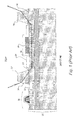
- Fig. 2 is a cross-section of an optical coupling structure.
- the optical coupling structure is formed in an SOI substrate 100 that includes a device layer 102, a BOX layer 104, and a bulk layer 106.
- the device layer 102 is located on the top side of the SOI substrate 100 and the bulk layer 106 is located on the bottom side of the SOI substrate 100.
- the BOX layer 104 is located substantially between the device layer 102 and the BOX layer 104.
- the device layer 102 includes a waveguide 108, which may be tailored to a variety of thickness in order to achieve desired optical characteristics of the waveguide (e.g., mode selection).
- the BOX layer 104 serves as a spacer in order to accurately set distance between a prism and the 108 waveguide and as a result, enable efficient and repeatable coupling of light into and out of the waveguide 108.
- BOX layer 104 should be thin enough (about 2500 Angstroms or less) to provide an adequate coupling between the prism 109 and the waveguide 108.
- the waveguide 108 should be surrounded by cladding layers that have a low index and sufficient thickness.
- an oxide layer 110 is grown or thermally deposited above the waveguide 108.
- the thickness of the cladding layers should be about 1um or more.
- the BOX layer 104 may also serve as a partial cladding layer below the waveguide 108.
- a cavity 111, which increases the thickness of the bottom cladding, is described with reference to Fig. 3.
- Fig. 2 also shows a FET 112 and a modulator 113 located within a vicinity of the waveguide 108. It should be noted that a variety of other optical elements may exist within or above the SOI substrate 100. In alternative examples, the waveguide 108 may be formed after the prism 109 is formed in the bottom side of the SOI substrate 100.
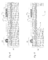
- Figs. 3A and 3B show at least two operating scenarios of the optical coupling structure of Fig. 2.
- Fig. 3A shows a light beam 114 that enters the prism 109 and refracts. BOX layer 104 assists in coupling beam 114 to the waveguide 108
- Fig. 3B shows a light beam 115 that transfers out of the waveguide 108 through the BOX layer 104 to the prism 124. It should be noted that at least a portion of the waveguide 108 and the prism 109 may be used to couple light into and out of the waveguide 108.
- Fig. 4 shows a cross-section of the SOI substrate 100 before the cavity 111 and the prism 109 are formed.
- the SOI substrate 100 may be provided at any point during a semiconductor process, such as after microelectronic devices are formed. Fig. 4 shows this example.
- Fig. 5 shows a cross-section of the SOI substrate 100 that includes the cavity 111, which, for instance, may have been created by a lithography process in combination with an etching step (i.e., a wet or dry etch).
- Cavity 111 should be aligned underneath the waveguide 108.
- a mask aligner e.g. a stepper
- Other methods of alignment include using an IR laser to detect and align front side features with a bottom side mask.
- alignment marks which can be recognized by the mask aligner, may be patterned into an appropriate layer of the SOI substrate 100 to enable registration of a backside pattern to a front side (or vice versa).
- the purpose of the cavity 111 may be at least two fold. Because the BOX layer 104 is thinner than a conventional oxide cladding layer (typically, about 1 um or more), the cavity 111 compensates for a lesser thickness of the BOX layer 104. The combination of the BOX layer 104 and the cavity 111 serve as the bottom cladding of the waveguide 108.
- the cavity 111 may also be filled with a material, such as an oxide or a nitride, as long as the index of the filled cavity remains less than that of the waveguide 108.
- the cavity 111 may also truncate light that propagates through the prism 109.
- a cavity edge 118 provides a transition between a low index medium (the cavity I I I) and a high index medium (the bulk layer 106), which provides a truncation of light at the BOX layer 104/prism 109 interface. The sharper the truncation, the better the coupling efficiency may be between the prism 109 and waveguide 108.
- an additional lithography step and etch step define a tapered surface for receiving or outputting a light beam.
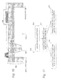
- Fig. 6 shows an upside down "V" shaped groove 120 formed in the bulk layer 106.
- An isotropic or an anisotropic etch may create the groove 120, according to a variety of orientations, such as a preferred crystallographic orientation, for instance.
- the etch may create a tapered surface 122 for receiving or outputting a beam of light.
- a crystollagraphic etch using tetramethylammonium hydroxide (TMAH) or potassium hydroxide (KOH), for example may be used to create a controlled and repeatable angle of the tapered surface 122 with respect to the SOI substrate 100. (Typically, the angle is about 54 degrees, but other etches could create a variety of other angles.).
- the cavity etch and the groove etch create the prism 109 that includes the groove 120 and is defined by the cavity edge 118.
- the groove 120 may be formed before the cavity edge 118.
- Fig. 7 shows a prism 200 that is bonded to the bottom side of an SOI substrate 201, which includes a device layer 202 located on top of a BOX layer 204.
- the device layer 202 also includes a waveguide 208.
- the BOX layer 204 is located on top of a bulk layer 206.
- a portion of the bulk layer 206 may be removed, exposing a portion of the BOX layer 204.
- the prism 200 which may be selected from a variety of pre-fabricated prisms, may then be bonded to the BOX layer 204.
- the prism 201 and the waveguide 208 may be operated in a similar manner to the optical coupling structure of Fig. 2.
- Fig. 8A shows a light beam 210 entering prism 200 and being coupled to the waveguide 208 via a coupling through a portion of the BOX layer 204.
- Fig. 8B shows a light beam 211, leaving the waveguide 208 and being coupled to the prism 201 via a coupling through the BOX layer 204.
- the BOX layer 104 should be thin enough (about 2500 Angstroms or less) to provide an adequate coupling between the prism 200 and the waveguide 208.
- Fig. 9 shows a cross section of the SOI substrate 201 that includes a cavity 212.
- the cavity 212 defines a location for the prism 200 to be bonded to and it also serves a similar function as the cavity 111, which includes promoting the truncation of light and confinement to the waveguide 108.
- the cavity 212 may also be formed in a similar manner as the cavity 111 using a variety of etching and lithography techniques.
- Fig. 10 shows the prism 200 bonded to the BOX layer 204.
- the prism 200 may be bonded to the BOX layer 204 using a variety of conventional bonding techniques.
- processing parameters such as temperature, pressure, etc.,
- the configuration shown in Fig. 10 may be advantageous because the prism 200 does not interfere with top side optical and electronic elements, and metal and dielectric layers.
- a variety of different types of prisms, even those that are made of a different material than silicon, may be incorporated into an optical coupling structure.
- Fig. 10 show a flow diagram that illustrates in a simplified manner a method 230 for fabricating an optical coupling structure that comprises a waveguide optically coupled through a BOX layer with a prism.
- Method 230 may be carried out on a substrate at a variety of points of a semiconductor process. For instance, method 230 may be applied before front-end optical and electrical elements are formed, during front-end processing, during back-end processing, or after back-end processing has been completed.
- an SOI substrate is provided.
- the SOI substrate includes at least a BOX layer that is sufficiently thin to provide an adequate coupling. In one example this thickness is 2500 Angstroms or less.
- the SOI substrate may also have a specific bulk layer background doping so that if the prism is formed out of the bulk layer, the background doping may establish the index of the prism.
- a waveguide is formed on a top side of the SOI substrate.
- the device layer may be thinned (via an etch or a planarization process) and doped to provide desired waveguide thickness and index.
- a waveguide may include multiple layers.
- the prism may be formed in the bulk layer at block 236 or bonded to the bottom side of the SOI substrate at block 238.
- a cavity may be formed that acts as a cladding layer and also promotes truncation at the BOX layer/prism interface.
- the bottom side of the SOI substrate may be treated in a variety of ways, which includes chemically etching and cleaning and/or polishing the bottom side to facilitate patterning/and or bonding (a double side polished wafer may also be provided).
- such treatment may provide a suitable bonding area for the prism.
- the bulk layer may be thinned or planarized in order to provide a desired thickness of the prism.
- a prism may be coated with an anti-reflective coating.
- the waveguide and the prism is not necessarily consecutive.
- the waveguide for instance, may be formed early in the front-end of a semiconductor process and the prism may be formed later in a back-end process.
- the prism may be formed first, before front-end processing, and the waveguide may be formed at some later point.
- a variety of other processing scenarios may create an optical coupling structure that uses a portion of the BOX layer of an SOI substrate to evanescently couple light between a prism located on the bottom of an SOI substrate with a waveguide located on top of the SOI substrate.
- the optical structure may either provide light to an optoelectronic IC or transfer light out of the IC. It should be understood, however, that the BOX layer may be used to couple other optical elements.
- the illustrated embodiments and related description are examples only and should not be taken as limiting the scope of the present invention.
- the term "tapered,” for example, when referring to the surface of a prism should not be viewed as limiting. A variety of similar terms, such as angled, faceted, or sloped could be substituted.
- the disclosure uses a silicon based substrate and prism as an example, a variety of other semiconductor substrates and films may be used instead of silicon and silicon dioxide, such as GaAs, GaN, or InP, for example.
- the indexes of any of the above films may be tailored in order to effectively couple light into and out of a waveguide.
- the index of the prism (n 1 ) may be larger than the indexes of both the waveguide (n 3 ) and the BOX layer (n 2 ).
Abstract
Description
- The present invention relates generally to optoelectronic integrated circuits and more particularly to an optical coupling structure that includes a silicon-based prism coupled with a waveguide. A method of making the structure using a silicon-on-insulator (SOI) substrate is also disclosed.
- Optoelectronic integrated circuits (ICs) include both electronic and optical elements within a single chip. Typical electronic elements include field effect transistors, capacitors, and, resistors; typical optical elements include waveguides, optical filters, modulators, and photodetectors. Within a given Optoelectronic IC, some of the electronic elements may be dedicated to handling tasks such as data storage and signal processing. Other electronic elements may be dedicated to controlling or modulating the optical elements. Including both types of elements on a single chip provides several advantages, which include reduced layout area, cost, and operational overhead. In addition, such integration yields hybrid devices, such as an opto-isolator.
- The integration of optical and electronic elements has been greatly facilitated by the maturation of today's semiconductor processing techniques. For instance, conventional processing techniques may be adapted to create silicon-based prisms, waveguides, and other optical devices.
- One device, however, that has been difficult to integrate is a silicon based laser or light source. As a result, most optoelectronic ICs are adapted to receive an externally applied light beam from a laser or an optical fiber. Unfortunately, introducing a light beam to an IC can often be difficult. For example, in order for an Optoelectronic IC to accommodate a light beam, the spot size and the numerical aperture (NA) of the beam may need to be appropriately matched to optical elements within an IC.
- To overcome these difficulties, previous methods use a silicon-based prism to couple a light beam into and out of a waveguide. To couple light into the waveguide, the prism receives an externally applied light beam and refracts it to a coupling region. The coupling region then provides the refracted light beam to the waveguide. A reverse scenario moves a light beam away from the waveguide, into a coupling region, which transfers the light beam into the prism. The prism then refracts the light beam out of the prism. To provide an evanescent coupling, the prism should be located within close proximity of the waveguide and should have an index of refraction that is greater than or equal to that of the waveguide. Further, the separation distance between the prism and waveguide should be small (on the order of 1000's of Angstroms) and the index of the medium that separates the two must be smaller than the indexes of both the prism and the waveguide. In many scenarios, the index of the prism (n1) is larger than the index of the separation medium (n2) and larger than or equal to the index of the waveguide (n3),
- In general, optoelectronic ICs are fabricated in SOI based substrates. Advantageously, SOI substrates provide a thin device layer located on top of a buried oxide (BOX) layer. The device layer is used for a waveguide and the BOX layer serves as a cladding layer of the waveguide. Fig. 1 shows an SOI substrate 10 that includes a
device layer 12, aBOX layer 14, and a bulk layer 16. Thedevice layer 12 includes awaveguide 18. Above thewaveguide 18 are acoupling region 20 and aprism 22 for optically coupling a light beam into thewaveguide 18. Thecoupling region 20 is an oxide layer that is either grown or deposited between thewaveguide 18 and theprism 22 Theprism 22 is a silicon based prism that is bonded to thecoupling region 20. The BOX layer 16 and athick oxide layer 24 serve as cladding layers of thewaveguide 18, and bothlayers 16, 24 have a thickness that is on the order of I um for sufficiently confining a light beam to thewaveguide 18. - Additionally, Fig. 1 shows a silicon-oxide-
silicon modulator 28 located above the waveguide 18 (where a portion of thewaveguide 18 silicon serves as a lower plate in the modulator 28) and a field effect transistor (FET) 30 adjacent to thewaveguide 18. Anoxide region 32, interposed between theFET 30 and thewaveguide 18, provides electrical isolation. When themodulator 28 receives a voltage bias, it may adapt the optical properties of a light beam within thewaveguide 18. The FET 30 may be included in a variety of modulator bias controls, signal processing, switching, or data storage related circuits, for instance. - To effectively couple a light beam into the
waveguide 18, theprism 22 includes atapered surface 34, which allows a variety of incident angles to be achieved. Theprism 22 may also include an anti-reflective coating that reduces Fresnel losses. Fig. 1 shows alight beam 36 incident on thetapered surface 34. Typically light beams used in optoelectronic ICs are in the infrared range of about 1-5 µm, which is transparent to silicon. Theprism 22 refracts thebeam 36 and thecoupling region 20 then assists in coupling thebeam 36 to thewaveguide 18. Thewaveguide 18 may then provide thebeam 36 to other portions of an IC, or another optical coupling structure, which may draw thebeam 36 out of thewaveguide 18. For instance, Fig. 1 shows aprism 38 and ancoupling region 40, which together may draw thebeam 36 out of thewaveguide 18. - One problem with current optoelectronic coupling structures is that bonding the prism to the coupling region is difficult. Typically, prisms are fabricated separately from a substrate and then later aligned to a coupling region and bonded. The alignment and bonding can be a labor intensive, time consuming task, which reduces throughput and makes larger scale production less feasible. In addition, interconnects, which electrically couple together various electronic elements, must also accommodate a prism. Often this leads to an increased number of restrictions in the layout rules of the contacts, vias, metal interconnects, and electrical and optical elements within a given optoelectronic IC.
- An optoelectronic coupling structure, a method of manufacture, and a method of operation are described. The optical coupling structure includes a waveguide, a coupling region, and a prism. The optical structure is fabricated within an SOI substrate that includes a device layer, a BOX layer, and a bulk layer. The waveguide and the prism are located on opposite sides of the SOI substrate. The waveguide, which is located in the device layer, is on the top side of the SOI substrate. The prism, on the other hand, is located on the other side of the SOI substrate. Advantageously, the BOX layers serves as a spacer region between the prism and the waveguide.
- In one example, an etch process forms the prism in the bulk layer. Instead of the prism being bonded to a coupling region above the device layer, the bottom side of the SOI substrate is patterned and etched. The etch process creates a prism that is within close proximity to both the waveguide and the coupling region. Because the BOX layer is grown from the bulk layer, an inherent bond naturally exists between the prism and the coupling region. Moreover, the BOX layer/prism interface is relatively defect free (relative to a prism that may have been bonded to a substrate).
- In another example, the prism is separately fabricated and later bonded to the bottom side of the SOI substrate. An etch process may first remove a portion of the bulk layer in order to provide a bonding surface on an exposed portion of the BOX layer. A bonding process may then bond the prism to the BOX layer.
- In another example, the BOX layer is about 2500 Angstroms or less in thickness. The prism may be adjacent to a cavity that is below the waveguide and the BOX layer. Because the BOX layer is less than 2500 Angstroms, the BOX layer may not be sufficiently thick enough to adequately confine a light beam to the waveguide. Therefore, the cavity increases the cladding thickness of the waveguide by using air, or by being filled with an oxide, a nitride or other low index material. The cavity may also truncate a refracted light beam within the prism to provide a more efficient coupling.
- In yet another respect, the prism may be formed at any point of a manufacturing process. For instance, the prism may be formed before or after optical and electronic elements are formed in the SOI substrate. The prism may also be formed after inter-level dielectrics, metal interconnects, and various other metal layers are deposited. As a result, layout requirements do not need to be restricted to accommodate the prism.
- A variety of manufacturing techniques associated with conventional semiconductor processing may be used to create the prism. Alternatively, adapted tooling and processes may also be used to properly align a prism with a waveguide and a coupling region. For instance, a mask aligner (e.g., a stepper) having a camera for bottom and top side alignment may ensure that a photoresist mask is aligned with a top side waveguide. The mask aligner may include an infrared laser source that optically detects desired structures in which a prism is to be aligned.
- These as well as other aspects and advantages will become apparent to those of ordinary skill in the art by reading the following detailed description, with reference where appropriate to the accompanying drawings. Further, it is understood that this summary is merely an example and is not intended to limit the scope of the invention as claimed.
- Certain example embodiments are described below in conjunction with the appended drawing figures, wherein like reference numerals refer to like elements in the various figures, and wherein:
- Figure 1 is a cross section of a prior art optical coupling structure, according to an example;
- Figure 2 is a cross section of an optical coupling structure, according to an example;
- Figures 3A and 3B are cross sections showing a light beam being evanescently coupled into and out of a waveguide, according to an example;
- Figure 4 is a cross section, of an SOI substrate, according to an example;
- Figure 5 is another cross section of an SOI substrate with a cavity located in the bulk layer, according to an example;
- Figure 6 is a cross section of an SOI substrate with a cavity and a groove located in the bulk layer, according to an example;
- Figure 7 is a cross section of another optical coupling structure, according to an example;
- Figures 8A and 8B are cross sections showing a light beam being evanescently coupled into and out of a waveguide, according to an example;
- Figure 9 is a cross section of an SOI substrate with a cavity located in the bulk layer for mounting a prism, according to an example;
- Figure 10 is a cross section of a prism mounted in the cavity of Fig. 9; and
- Figure 11 is a flow diagram of a method of forming an optical coupling structure, according to an example.
- In one form or another, the various embodiments describe an optical coupling structure that receives a light beam and couples the beam into a waveguide. In a reverse manner, the optical coupling structure may also move light away from the waveguide and out of an optoelectronic IC. The methods of fabricating such an optical structure described below implement a variety of conventional semiconductor processes and combinations thereof, which include: lithography, etching, thin-film deposition, and anti-reflective coatings. Moreover, some of the embodiments also include methods that may employ conventional wafer to wafer attachment/bonding processes.
- For simplicity, the description below and related figures describe an optical coupling structure that includes a silicon-based waveguide that consists of single crystalline silicon layer. In alternative embodiments the waveguide may be polycrystalline silicon and it may also comprise multiple layers with specific characteristics for each individual layer (i.e., doping, thickness, resistivity, etc.). The thickness of the waveguide may be tailored to accommodate one or more modes of a propagating light beam. In addition, although the described embodiments below use silicon-based optical elements, other types of high index materials (i.e., gallium arsenide, lithium niobate, indium phosphide, etc.) may replace silicon-based elements. Further, the waveguide, prism, and coupling regions may take on a variety of shapes and sizes. In general, the term prism refers to any device that may receive a light beam and produce a desired refraction.
- Turning now to the figures, Fig. 2 is a cross-section of an optical coupling structure. The optical coupling structure is formed in an
SOI substrate 100 that includes adevice layer 102, aBOX layer 104, and abulk layer 106. Thedevice layer 102 is located on the top side of theSOI substrate 100 and thebulk layer 106 is located on the bottom side of theSOI substrate 100. TheBOX layer 104 is located substantially between thedevice layer 102 and theBOX layer 104. Thedevice layer 102 includes awaveguide 108, which may be tailored to a variety of thickness in order to achieve desired optical characteristics of the waveguide (e.g., mode selection). - To introduce a light beam into the
waveguide 108 or draw light out of thewaveguide 108, theBOX layer 104 serves as a spacer in order to accurately set distance between a prism and the 108 waveguide and as a result, enable efficient and repeatable coupling of light into and out of thewaveguide 108. Thus,BOX layer 104 should be thin enough (about 2500 Angstroms or less) to provide an adequate coupling between theprism 109 and thewaveguide 108. - To efficiently guide the light beam, the
waveguide 108 should be surrounded by cladding layers that have a low index and sufficient thickness. To clad thewaveguide 108, anoxide layer 110 is grown or thermally deposited above thewaveguide 108. In one example, the thickness of the cladding layers should be about 1um or more. TheBOX layer 104 may also serve as a partial cladding layer below thewaveguide 108. Acavity 111, which increases the thickness of the bottom cladding, is described with reference to Fig. 3. - Fig. 2 also shows a
FET 112 and amodulator 113 located within a vicinity of thewaveguide 108. It should be noted that a variety of other optical elements may exist within or above theSOI substrate 100. In alternative examples, thewaveguide 108 may be formed after theprism 109 is formed in the bottom side of theSOI substrate 100. - Figs. 3A and 3B show at least two operating scenarios of the optical coupling structure of Fig. 2. To bring light into the
waveguide 108, Fig. 3A shows alight beam 114 that enters theprism 109 and refracts.BOX layer 104 assists incoupling beam 114 to thewaveguide 108 To bring light out of thewaveguide 108, Fig. 3B shows alight beam 115 that transfers out of thewaveguide 108 through theBOX layer 104 to theprism 124. It should be noted that at least a portion of thewaveguide 108 and theprism 109 may be used to couple light into and out of thewaveguide 108. - Fig. 4 shows a cross-section of the
SOI substrate 100 before thecavity 111 and theprism 109 are formed. Advantageously theSOI substrate 100 may be provided at any point during a semiconductor process, such as after microelectronic devices are formed. Fig. 4 shows this example. - Fig. 5 shows a cross-section of the
SOI substrate 100 that includes thecavity 111, which, for instance, may have been created by a lithography process in combination with an etching step (i.e., a wet or dry etch).Cavity 111 should be aligned underneath thewaveguide 108. In order to align thecavity 111, a mask aligner (e.g. a stepper) may include a camera for aligning a mask to features on the top side of theSOI substrate 100. Other methods of alignment include using an IR laser to detect and align front side features with a bottom side mask. In such examples, alignment marks, which can be recognized by the mask aligner, may be patterned into an appropriate layer of theSOI substrate 100 to enable registration of a backside pattern to a front side (or vice versa). - The purpose of the
cavity 111 may be at least two fold. Because theBOX layer 104 is thinner than a conventional oxide cladding layer (typically, about 1 um or more), thecavity 111 compensates for a lesser thickness of theBOX layer 104. The combination of theBOX layer 104 and thecavity 111 serve as the bottom cladding of thewaveguide 108. Thecavity 111 may also be filled with a material, such as an oxide or a nitride, as long as the index of the filled cavity remains less than that of thewaveguide 108. - The
cavity 111 may also truncate light that propagates through theprism 109. Acavity edge 118 provides a transition between a low index medium (the cavity I I I) and a high index medium (the bulk layer 106), which provides a truncation of light at theBOX layer 104/prism 109 interface. The sharper the truncation, the better the coupling efficiency may be between theprism 109 andwaveguide 108. - To form the
prism 109, an additional lithography step and etch step define a tapered surface for receiving or outputting a light beam. Fig. 6 shows an upside down "V" shapedgroove 120 formed in thebulk layer 106. An isotropic or an anisotropic etch may create thegroove 120, according to a variety of orientations, such as a preferred crystallographic orientation, for instance. The etch may create atapered surface 122 for receiving or outputting a beam of light. In general, a crystollagraphic etch using tetramethylammonium hydroxide (TMAH) or potassium hydroxide (KOH), for example, may be used to create a controlled and repeatable angle of the taperedsurface 122 with respect to theSOI substrate 100. (Typically, the angle is about 54 degrees, but other etches could create a variety of other angles.). - Although the groove is shown as an upside down "V-shaped groove," other types of grooves and tapered surfaces are also possible. The cavity etch and the groove etch create the
prism 109 that includes thegroove 120 and is defined by thecavity edge 118. In some examples thegroove 120 may be formed before thecavity edge 118. - Because the
prism 109 is formed inbulk layer 106, theprism 109 is inherently bonded to a portion of theBOX layer 104. Consequently, a relatively defect free bond may exist been theprism 109 and thebulk layer 106. As another example, however, Fig. 7 shows aprism 200 that is bonded to the bottom side of anSOI substrate 201, which includes adevice layer 202 located on top of aBOX layer 204. Thedevice layer 202 also includes awaveguide 208. TheBOX layer 204 is located on top of abulk layer 206. Instead of forming theprism 201 out of thebulk layer 206, a portion of thebulk layer 206 may be removed, exposing a portion of theBOX layer 204. Theprism 200, which may be selected from a variety of pre-fabricated prisms, may then be bonded to theBOX layer 204. - The
prism 201 and thewaveguide 208 may be operated in a similar manner to the optical coupling structure of Fig. 2. Fig. 8A shows alight beam 210 enteringprism 200 and being coupled to thewaveguide 208 via a coupling through a portion of theBOX layer 204. Fig. 8B, on the other hand, shows alight beam 211, leaving thewaveguide 208 and being coupled to theprism 201 via a coupling through theBOX layer 204. As described above, theBOX layer 104 should be thin enough (about 2500 Angstroms or less) to provide an adequate coupling between theprism 200 and thewaveguide 208. - Fig. 9 shows a cross section of the
SOI substrate 201 that includes acavity 212. Thecavity 212 defines a location for theprism 200 to be bonded to and it also serves a similar function as thecavity 111, which includes promoting the truncation of light and confinement to thewaveguide 108. Thecavity 212 may also be formed in a similar manner as thecavity 111 using a variety of etching and lithography techniques. - Fig. 10 shows the
prism 200 bonded to theBOX layer 204. Theprism 200 may be bonded to theBOX layer 204 using a variety of conventional bonding techniques. When bonding theprism 200, processing parameters (such as temperature, pressure, etc.,) should be compatible with the materials and structures present in the optical coupling structure or within theSOI substrate 200. The configuration shown in Fig. 10 may be advantageous because theprism 200 does not interfere with top side optical and electronic elements, and metal and dielectric layers. Moreover, a variety of different types of prisms, even those that are made of a different material than silicon, may be incorporated into an optical coupling structure. - As an overview, Fig. 10 show a flow diagram that illustrates in a simplified manner a
method 230 for fabricating an optical coupling structure that comprises a waveguide optically coupled through a BOX layer with a prism.Method 230 may be carried out on a substrate at a variety of points of a semiconductor process. For instance,method 230 may be applied before front-end optical and electrical elements are formed, during front-end processing, during back-end processing, or after back-end processing has been completed. - At
block 232, an SOI substrate is provided. The SOI substrate includes at least a BOX layer that is sufficiently thin to provide an adequate coupling. In one example this thickness is 2500 Angstroms or less. The SOI substrate may also have a specific bulk layer background doping so that if the prism is formed out of the bulk layer, the background doping may establish the index of the prism. - At
block 234, a waveguide is formed on a top side of the SOI substrate. The device layer may be thinned (via an etch or a planarization process) and doped to provide desired waveguide thickness and index. As described above, a waveguide may include multiple layers. - The prism may be formed in the bulk layer at
block 236 or bonded to the bottom side of the SOI substrate atblock 238. As described above, a cavity may be formed that acts as a cladding layer and also promotes truncation at the BOX layer/prism interface. In order to accommodate the prism, the bottom side of the SOI substrate may be treated in a variety of ways, which includes chemically etching and cleaning and/or polishing the bottom side to facilitate patterning/and or bonding (a double side polished wafer may also be provided). Atblock 236, such treatment may provide a suitable bonding area for the prism. On the other hand, atblock 238, the bulk layer may be thinned or planarized in order to provide a desired thickness of the prism. Although not shown, to reduce Fresnel losses, a prism may be coated with an anti-reflective coating. - It is important to note that the formation of the waveguide and the prism is not necessarily consecutive. The waveguide, for instance, may be formed early in the front-end of a semiconductor process and the prism may be formed later in a back-end process. Alternatively, the prism may be formed first, before front-end processing, and the waveguide may be formed at some later point. A variety of other formation scenarios exist.
- A variety of other processing scenarios may create an optical coupling structure that uses a portion of the BOX layer of an SOI substrate to evanescently couple light between a prism located on the bottom of an SOI substrate with a waveguide located on top of the SOI substrate. In general, the optical structure may either provide light to an optoelectronic IC or transfer light out of the IC. It should be understood, however, that the BOX layer may be used to couple other optical elements.
- The illustrated embodiments and related description are examples only and should not be taken as limiting the scope of the present invention. The term "tapered," for example, when referring to the surface of a prism should not be viewed as limiting. A variety of similar terms, such as angled, faceted, or sloped could be substituted. Moreover, although the disclosure uses a silicon based substrate and prism as an example, a variety of other semiconductor substrates and films may be used instead of silicon and silicon dioxide, such as GaAs, GaN, or InP, for example. In addition, the indexes of any of the above films may be tailored in order to effectively couple light into and out of a waveguide. For example, the index of the prism (n1) may be larger than the indexes of both the waveguide (n3) and the BOX layer (n2). The claims should not be read as limited to the described order or elements unless stated to that effect. Therefore, all embodiments that come within the scope and spirit of the following claims and equivalents thereto are claimed as the invention.
Claims (7)
- An optical coupling structure, comprising:a silicon-on-insulator substrate comprising a top side and a bottom side, wherein a buried oxide layer is interposed between the top side and the bottom side;a wave guide formed on the top side; anda prism formed on the bottom side, wherein a portion of the buried oxide layer serves as a spacer between the prism and the waveguide.
- The optical coupling structure as in claim 1, wherein the portion of the buried oxide layer promotes an optical coupling between the prism and the waveguide.
- The optical coupling structure as in claim 1, wherein the waveguide is formed in a device layer and the prism is formed in a bulk layer.
- The optical coupling structure as in claim 3, wherein the bulk layer has a first refractive index (n1), the buried oxide layer has a second refractive index (n2), and the device layer has third refractive index (n3), and wherein n1 ≥ n3 > n2.
- The optical coupling structure as in claim 1, wherein a thickness of the buried oxide layer is less than about 2500 Angstroms.
- The optical coupling structure as in claim 1, further comprising:a cladding region that is located adjacent to the prism and below the waveguide and the buried oxide layer.
- The optical coupling structure as in claim 6, wherein the cladding layer is selected from the group consisting of an oxide, a nitride, and air.
Applications Claiming Priority (1)
| Application Number | Priority Date | Filing Date | Title |
|---|---|---|---|
| US11/412,738 US7454102B2 (en) | 2006-04-26 | 2006-04-26 | Optical coupling structure |
Publications (1)
| Publication Number | Publication Date |
|---|---|
| EP1850160A1 true EP1850160A1 (en) | 2007-10-31 |
Family
ID=38197664
Family Applications (1)
| Application Number | Title | Priority Date | Filing Date |
|---|---|---|---|
| EP07106879A Withdrawn EP1850160A1 (en) | 2006-04-26 | 2007-04-24 | Optical coupling structure |
Country Status (3)
| Country | Link |
|---|---|
| US (1) | US7454102B2 (en) |
| EP (1) | EP1850160A1 (en) |
| SG (1) | SG136921A1 (en) |
Cited By (7)
| Publication number | Priority date | Publication date | Assignee | Title |
|---|---|---|---|---|
| WO2008058099A2 (en) * | 2006-11-07 | 2008-05-15 | Honeywell International Inc. | Low-loss optical device structure |
| CN102122034A (en) * | 2010-01-11 | 2011-07-13 | 联华电子股份有限公司 | Photoelectric element and forming method thereof |
| CN101364656B (en) * | 2008-09-23 | 2012-02-22 | 吉林大学 | Single chip integrated micro-wave light quantum phase shifter based on SOI optical waveguide and preparation |
| WO2014042716A1 (en) * | 2012-06-04 | 2014-03-20 | Micron Technology, Inc. | Method and structure providing optical isolation of a waveguide on a silicon-on-insulator substrate |
| EP2703856A3 (en) * | 2012-08-29 | 2014-06-04 | Aurrion, Inc. | Thermal management for photonic integrated circuits |
| WO2014133760A1 (en) * | 2013-02-26 | 2014-09-04 | Micron Technology, Inc. | Photonic device structure and method of manufacture |
| US9509122B1 (en) | 2012-08-29 | 2016-11-29 | Aurrion, Inc. | Optical cladding layer design |
Families Citing this family (50)
| Publication number | Priority date | Publication date | Assignee | Title |
|---|---|---|---|---|
| WO2007014218A2 (en) | 2005-07-25 | 2007-02-01 | Massachusetts Institute Of Technology | Wide free-spectral-range, widely tunable and hitless-switchable optical channel add-drop filters |
| US7574090B2 (en) * | 2006-05-12 | 2009-08-11 | Toshiba America Electronic Components, Inc. | Semiconductor device using buried oxide layer as optical wave guides |
| US8105758B2 (en) * | 2006-07-11 | 2012-01-31 | Massachusetts Institute Of Technology | Microphotonic maskless lithography |
| WO2008021467A2 (en) * | 2006-08-16 | 2008-02-21 | Massachusetts Institute Of Technology | Balanced bypass circulators and folded universally-balanced interferometers |
| US7853108B2 (en) | 2006-12-29 | 2010-12-14 | Massachusetts Institute Of Technology | Fabrication-tolerant waveguides and resonators |
| WO2008118465A2 (en) | 2007-03-26 | 2008-10-02 | Massachusetts Institute Of Technology | Hitless tuning and switching of optical resonator amplitude and phase responses |
| WO2009055440A2 (en) | 2007-10-22 | 2009-04-30 | Massachusetts Institute Of Technology | Low-loss bloch wave guiding in open structures and highly compact efficient waveguide-crossing arrays |
| US7920770B2 (en) * | 2008-05-01 | 2011-04-05 | Massachusetts Institute Of Technology | Reduction of substrate optical leakage in integrated photonic circuits through localized substrate removal |
| US8831437B2 (en) | 2009-09-04 | 2014-09-09 | Luxtera, Inc. | Method and system for a photonic interposer |
| US8877616B2 (en) * | 2008-09-08 | 2014-11-04 | Luxtera, Inc. | Method and system for monolithic integration of photonics and electronics in CMOS processes |
| WO2010065710A1 (en) | 2008-12-03 | 2010-06-10 | Massachusetts Institute Of Technology | Resonant optical modulators |
| WO2010138849A1 (en) | 2009-05-29 | 2010-12-02 | Massachusetts Institute Of Technology | Cavity dynamics compensation in resonant optical modulators |
| US8139907B2 (en) * | 2009-12-29 | 2012-03-20 | United Microelectronics Corp. | Optoelectronic device and method of forming the same |
| US20110158582A1 (en) * | 2009-12-30 | 2011-06-30 | Tzung-I Su | Structure of a semiconductor device having a waveguide and method of forming the same |
| US8805130B2 (en) | 2010-03-16 | 2014-08-12 | Cornell University | Semiconductor high-speed integrated electro-optic devices and methods |
| US8300990B2 (en) * | 2010-04-14 | 2012-10-30 | Oracle America, Inc. | Slotted optical waveguide with electro-optic material |
| US8399292B2 (en) | 2010-06-30 | 2013-03-19 | International Business Machines Corporation | Fabricating a semiconductor chip with backside optical vias |
| US9624096B2 (en) | 2010-12-24 | 2017-04-18 | Qualcomm Incorporated | Forming semiconductor structure with device layers and TRL |
| US9754860B2 (en) | 2010-12-24 | 2017-09-05 | Qualcomm Incorporated | Redistribution layer contacting first wafer through second wafer |
| US8481405B2 (en) | 2010-12-24 | 2013-07-09 | Io Semiconductor, Inc. | Trap rich layer with through-silicon-vias in semiconductor devices |
| US8536021B2 (en) | 2010-12-24 | 2013-09-17 | Io Semiconductor, Inc. | Trap rich layer formation techniques for semiconductor devices |
| US9553013B2 (en) | 2010-12-24 | 2017-01-24 | Qualcomm Incorporated | Semiconductor structure with TRL and handle wafer cavities |
| EP2656388B1 (en) | 2010-12-24 | 2020-04-15 | QUALCOMM Incorporated | Trap rich layer for semiconductor devices |
| US8869235B2 (en) | 2011-10-11 | 2014-10-21 | Citrix Systems, Inc. | Secure mobile browser for protecting enterprise data |
| US9280377B2 (en) | 2013-03-29 | 2016-03-08 | Citrix Systems, Inc. | Application with multiple operation modes |
| US9599561B2 (en) | 2011-10-13 | 2017-03-21 | Affymetrix, Inc. | Methods, systems and apparatuses for testing and calibrating fluorescent scanners |
| US8901576B2 (en) | 2012-01-18 | 2014-12-02 | International Business Machines Corporation | Silicon photonics wafer using standard silicon-on-insulator processes through substrate removal or transfer |
| US9285554B2 (en) | 2012-02-10 | 2016-03-15 | International Business Machines Corporation | Through-substrate optical coupling to photonics chips |
| US8910239B2 (en) | 2012-10-15 | 2014-12-09 | Citrix Systems, Inc. | Providing virtualized private network tunnels |
| US20140109072A1 (en) | 2012-10-16 | 2014-04-17 | Citrix Systems, Inc. | Application wrapping for application management framework |
| US9971585B2 (en) | 2012-10-16 | 2018-05-15 | Citrix Systems, Inc. | Wrapping unmanaged applications on a mobile device |
| US9387815B2 (en) | 2013-02-28 | 2016-07-12 | Kevin Goldstein | Apparatus for collection of debris escaping around a vehicle tailgate |
| US9985850B2 (en) | 2013-03-29 | 2018-05-29 | Citrix Systems, Inc. | Providing mobile device management functionalities |
| US9413736B2 (en) | 2013-03-29 | 2016-08-09 | Citrix Systems, Inc. | Providing an enterprise application store |
| US9355223B2 (en) | 2013-03-29 | 2016-05-31 | Citrix Systems, Inc. | Providing a managed browser |
| US10284627B2 (en) | 2013-03-29 | 2019-05-07 | Citrix Systems, Inc. | Data management for an application with multiple operation modes |
| US9209075B2 (en) * | 2013-06-25 | 2015-12-08 | Globalfoundries Inc. | Integration of optical components in integrated circuits |
| US9772461B2 (en) * | 2013-10-02 | 2017-09-26 | Photonics Electronics Technology Research Association | Semiconductor integrated circuit and method for manufacturing the same |
| US20150125110A1 (en) * | 2013-11-04 | 2015-05-07 | Cisco Technology, Inc. | Passively Placed Vertical Optical Connector |
| US9772463B2 (en) * | 2014-09-04 | 2017-09-26 | International Business Machines Corporation | Intra chip optical interconnect structure |
| US10135218B2 (en) | 2015-10-02 | 2018-11-20 | Ayar Labs, Inc. | Multi-wavelength laser system for optical data communication links and associated methods |
| US10078183B2 (en) * | 2015-12-11 | 2018-09-18 | Globalfoundries Inc. | Waveguide structures used in phonotics chip packaging |
| US10620371B2 (en) * | 2016-03-05 | 2020-04-14 | Huawei Technologies Canada Co., Ltd. | Waveguide crossing having rib waveguides |
| JP2018077264A (en) * | 2016-11-07 | 2018-05-17 | ルネサスエレクトロニクス株式会社 | Semiconductor device and manufacturing method therefor |
| JP2018146669A (en) * | 2017-03-02 | 2018-09-20 | 富士通株式会社 | Optical semiconductor and manufacturing method thereof |
| US10976542B2 (en) | 2018-01-26 | 2021-04-13 | Analog Photonics LLC | Aberration correction of optical phased arrays |
| US10775559B2 (en) | 2018-01-26 | 2020-09-15 | Analog Photonics LLC | Photonics fabrication process performance improvement |
| US11101617B2 (en) | 2018-07-16 | 2021-08-24 | Ayar Labs, Inc. | Wafer-level handle replacement |
| US10466514B1 (en) * | 2018-11-06 | 2019-11-05 | Globalfoundries Inc. | Electro-optic modulator with vertically-arranged optical paths |
| US11803009B2 (en) * | 2022-02-25 | 2023-10-31 | Globalfoundries U.S. Inc. | Photonics structures having a locally-thickened dielectric layer |
Citations (4)
| Publication number | Priority date | Publication date | Assignee | Title |
|---|---|---|---|---|
| US20040114869A1 (en) * | 2001-06-15 | 2004-06-17 | Fike Eugene E. | Mode converter including tapered waveguide for optically coupling photonic devices |
| WO2004088715A2 (en) * | 2003-03-28 | 2004-10-14 | Si Optical, Inc. | Tapered structure for providing coupling between external optical device and planar optical waveguide and method of forming the same |
| US20040202418A1 (en) * | 2003-04-10 | 2004-10-14 | Margaret Ghiron | Beam shaping and practical methods of reducing loss associated with mating external sources and optics to thin silicon waveguides |
| WO2004095084A2 (en) * | 2003-04-23 | 2004-11-04 | Siophcal, Inc. | Sub-micron planar lightwave devices formed on an soi optical platform |
Family Cites Families (117)
| Publication number | Priority date | Publication date | Assignee | Title |
|---|---|---|---|---|
| US4059338A (en) * | 1975-09-09 | 1977-11-22 | Sharp Kabushiki Kaisha | Integrated optical waveguide coupler |
| US4234357A (en) | 1979-07-16 | 1980-11-18 | Trw Inc. | Process for manufacturing emitters by diffusion from polysilicon |
| US4315693A (en) | 1979-12-31 | 1982-02-16 | Walker Clifford G | Optical strapdown inertia system |
| US4673293A (en) | 1985-01-31 | 1987-06-16 | Honeywell Inc. | Passive cavity gyro bias eliminator |
| US5163118A (en) | 1986-11-10 | 1992-11-10 | The United States Of America As Represented By The Secretary Of The Air Force | Lattice mismatched hetrostructure optical waveguide |
| US4886345A (en) | 1988-08-05 | 1989-12-12 | Harris Corporation | Electro-optical phase modulator |
| GB2221999B (en) | 1988-08-16 | 1992-09-16 | Plessey Co Plc | Optical phase modulator |
| US4958898A (en) | 1989-03-15 | 1990-09-25 | The United States Of America As Represented By The Secretary Of The Air Force | Silicon double-injection electro-optic modulator with insulated-gate and method of using same |
| EP0393987A3 (en) | 1989-04-19 | 1992-08-05 | British Aerospace Public Limited Company | Ring resonator gyro |
| US5143577A (en) | 1991-02-08 | 1992-09-01 | Hoechst Celanese Corporation | Smooth-wall polymeric channel and rib waveguides exhibiting low optical loss |
| KR0134763B1 (en) | 1992-04-21 | 1998-04-23 | 다니이 아끼오 | Optical guided wave device and amnufacturing method |
| US5383048A (en) | 1993-02-03 | 1995-01-17 | Seaver; George | Stress-optical phase modulator and modulation system and method of use |
| KR960011653B1 (en) | 1993-04-16 | 1996-08-24 | 현대전자산업 주식회사 | Dram cell and the method |
| JP3377794B2 (en) | 1993-09-21 | 2003-02-17 | ブッカム・テクノロジイ・ピイエルシイ | Electro-optic device |
| US5429981A (en) | 1994-06-30 | 1995-07-04 | Honeywell Inc. | Method of making linear capacitors for high temperature applications |
| US5696662A (en) | 1995-08-21 | 1997-12-09 | Honeywell Inc. | Electrostatically operated micromechanical capacitor |
| JP2817703B2 (en) | 1996-04-25 | 1998-10-30 | 日本電気株式会社 | Optical semiconductor device |
| US5832165A (en) | 1996-08-28 | 1998-11-03 | University Of Utah Research Foundation | Composite waveguide for solid phase binding assays |
| US5841931A (en) | 1996-11-26 | 1998-11-24 | Massachusetts Institute Of Technology | Methods of forming polycrystalline semiconductor waveguides for optoelectronic integrated circuits, and devices formed thereby |
| US5861651A (en) | 1997-02-28 | 1999-01-19 | Lucent Technologies Inc. | Field effect devices and capacitors with improved thin film dielectrics and method for making same |
| US6147362A (en) | 1997-03-17 | 2000-11-14 | Honeywell International Inc. | High performance display pixel for electronics displays |
| US5917967A (en) | 1997-05-21 | 1999-06-29 | The United States Of America As Represented By The Secretary Of The Army | Techniques for forming optical electronic integrated circuits having interconnects in the form of semiconductor waveguides |
| SG70141A1 (en) | 1997-12-26 | 2000-01-25 | Canon Kk | Sample separating apparatus and method and substrate manufacturing method |
| US6108212A (en) | 1998-06-05 | 2000-08-22 | Motorola, Inc. | Surface-mount device package having an integral passive component |
| US6381380B1 (en) | 1998-06-24 | 2002-04-30 | The Trustees Of Princeton University | Twin waveguide based design for photonic integrated circuits |
| US6270604B1 (en) | 1998-07-23 | 2001-08-07 | Molecular Optoelectronics Corporation | Method for fabricating an optical waveguide |
| JP2000124092A (en) | 1998-10-16 | 2000-04-28 | Shin Etsu Handotai Co Ltd | Manufacture of soi wafer by hydrogen-ion implantation stripping method and soi wafer manufactured thereby |
| EP0995971A3 (en) | 1998-10-19 | 2000-10-18 | Canon Kabushiki Kaisha | Gyro and method of operating the same |
| GB2343293B (en) | 1998-10-23 | 2003-05-14 | Bookham Technology Ltd | Manufacture of a silicon waveguide structure |
| JP4416055B2 (en) | 1998-12-01 | 2010-02-17 | ローム株式会社 | Ferroelectric memory and manufacturing method thereof |
| US6323985B1 (en) | 1998-12-30 | 2001-11-27 | Intel Corporation | Mosfet through silicon modulator and method |
| US6587605B2 (en) | 1999-01-06 | 2003-07-01 | Intel Corporation | Method and apparatus for providing optical interconnection |
| US6150266A (en) | 1999-01-28 | 2000-11-21 | Vlsi Technology, Inc. | Local interconnect formed using silicon spacer |
| US6627954B1 (en) | 1999-03-19 | 2003-09-30 | Silicon Wave, Inc. | Integrated circuit capacitor in a silicon-on-insulator integrated circuit |
| JP2001111160A (en) | 1999-04-19 | 2001-04-20 | Canon Inc | Manufacturing method for semiconductor device, semiconductor device, ring resonator semiconductor laser, and gyro |
| US6137117A (en) | 1999-06-21 | 2000-10-24 | The United States Of America As Represented By The Secretary Of The Navy | Integrating multi-waveguide sensor |
| US6555288B1 (en) * | 1999-06-21 | 2003-04-29 | Corning Incorporated | Optical devices made from radiation curable fluorinated compositions |
| JP2001042150A (en) | 1999-07-30 | 2001-02-16 | Canon Inc | Optical waveguide, its manufacture and optical interconnecting device using it |
| SE0000148D0 (en) * | 2000-01-17 | 2000-01-17 | Forskarpatent I Syd Ab | Manufacturing method for IR detector matrices |
| US6546538B1 (en) | 2000-03-10 | 2003-04-08 | Lsi Logic Corporation | Integrated circuit having on-chip capacitors for supplying power to portions of the circuit requiring high-transient peak power |
| FR2810991B1 (en) | 2000-06-28 | 2004-07-09 | Inst Francais Du Petrole | PROCESS FOR HYDROGENATING CUTS CONTAINING HYDROCARBONS AND IN PARTICULAR UNSATURATED MOLECULES CONTAINING AT LEAST TWO DOUBLE LINKS OR AT LEAST ONE TRIPLE LINK |
| JP4961634B2 (en) | 2000-07-07 | 2012-06-27 | Kddi株式会社 | Optical gate device |
| US6850683B2 (en) | 2000-07-10 | 2005-02-01 | Massachusetts Institute Of Technology | Low-loss waveguide and method of making same |
| US6674108B2 (en) * | 2000-12-20 | 2004-01-06 | Honeywell International Inc. | Gate length control for semiconductor chip design |
| FR2819893B1 (en) * | 2001-01-25 | 2003-10-17 | Opsitech Optical System Chip | INTEGRATED OPTICAL STRUCTURE WITH REDUCED BIREFRINGENCE |
| US6603166B2 (en) | 2001-03-14 | 2003-08-05 | Honeywell International Inc. | Frontside contact on silicon-on-insulator substrate |
| US6633716B2 (en) | 2001-05-02 | 2003-10-14 | Motorola, Inc. | Optical device and method therefor |
| US6898352B2 (en) | 2001-05-17 | 2005-05-24 | Sioptical, Inc. | Optical waveguide circuit including passive optical waveguide device combined with active optical waveguide device, and method for making same |
| US6603889B2 (en) | 2001-05-17 | 2003-08-05 | Optronx, Inc. | Optical deflector apparatus and associated method |
| US6842546B2 (en) | 2001-05-17 | 2005-01-11 | Sioptical, Inc. | Polyloaded optical waveguide device in combination with optical coupler, and method for making same |
| US6912330B2 (en) | 2001-05-17 | 2005-06-28 | Sioptical Inc. | Integrated optical/electronic circuits and associated methods of simultaneous generation thereof |
| US6625348B2 (en) | 2001-05-17 | 2003-09-23 | Optron X, Inc. | Programmable delay generator apparatus and associated method |
| US6760498B2 (en) | 2001-05-17 | 2004-07-06 | Sioptical, Inc. | Arrayed waveguide grating, and method of making same |
| US6493502B1 (en) | 2001-05-17 | 2002-12-10 | Optronx, Inc. | Dynamic gain equalizer method and associated apparatus |
| US6748125B2 (en) | 2001-05-17 | 2004-06-08 | Sioptical, Inc. | Electronic semiconductor control of light in optical waveguide |
| US6654511B2 (en) | 2001-05-17 | 2003-11-25 | Sioptical, Inc. | Optical modulator apparatus and associated method |
| US6891985B2 (en) | 2001-05-17 | 2005-05-10 | Sioptical, Inc. | Polyloaded optical waveguide devices and methods for making same |
| US6891685B2 (en) | 2001-05-17 | 2005-05-10 | Sioptical, Inc. | Anisotropic etching of optical components |
| US6738546B2 (en) | 2001-05-17 | 2004-05-18 | Sioptical, Inc. | Optical waveguide circuit including multiple passive optical waveguide devices, and method of making same |
| US6608945B2 (en) | 2001-05-17 | 2003-08-19 | Optronx, Inc. | Self-aligning modulator method and associated apparatus |
| US6690863B2 (en) | 2001-05-17 | 2004-02-10 | Si Optical, Inc. | Waveguide coupler and method for making same |
| US6963118B2 (en) | 2001-05-17 | 2005-11-08 | Sioptical, Inc. | Hybrid active and electronic circuit with evanescent coupling |
| US6526187B1 (en) | 2001-05-17 | 2003-02-25 | Optronx, Inc. | Polarization control apparatus and associated method |
| US6690844B2 (en) | 2001-05-17 | 2004-02-10 | Optronx, Inc. | Optical fiber apparatus and associated method |
| US6646747B2 (en) | 2001-05-17 | 2003-11-11 | Sioptical, Inc. | Interferometer apparatus and associated method |
| US6658173B2 (en) | 2001-05-17 | 2003-12-02 | Optronx, Inc. | Interferometer and method of making same |
| US6947615B2 (en) | 2001-05-17 | 2005-09-20 | Sioptical, Inc. | Optical lens apparatus and associated method |
| US6596570B2 (en) | 2001-06-06 | 2003-07-22 | International Business Machines Corporation | SOI device with reduced junction capacitance |
| US20030026571A1 (en) | 2001-07-31 | 2003-02-06 | Michael Bazylenko | Method of reducing sidewall roughness of a waveguide |
| US6917727B2 (en) | 2001-09-10 | 2005-07-12 | California Institute Of Technology | Strip loaded waveguide integrated with electronics components |
| US6816636B2 (en) | 2001-09-12 | 2004-11-09 | Honeywell International Inc. | Tunable optical filter |
| JP3755588B2 (en) | 2001-10-03 | 2006-03-15 | 日本電気株式会社 | Light control device |
| US6580863B2 (en) * | 2001-10-31 | 2003-06-17 | Intel Corporation | System and method for providing integrated optical waveguide device |
| US20030098289A1 (en) * | 2001-11-29 | 2003-05-29 | Dawei Zheng | Forming an optical mode transformer |
| US6879751B2 (en) | 2002-01-30 | 2005-04-12 | Sioptical, Inc. | Method and apparatus for altering the effective mode index of an optical waveguide |
| JP3955764B2 (en) * | 2002-02-08 | 2007-08-08 | 富士通株式会社 | Optical modulator equipped with an element that changes the optical phase by electro-optic effect |
| JP2003234410A (en) * | 2002-02-08 | 2003-08-22 | Fujitsu Ltd | Capacitor, method for manufacturing the same, and semiconductor device |
| IL148716A0 (en) | 2002-03-14 | 2002-09-12 | Yissum Res Dev Co | Control of optical signals by mos (cosmos) device |
| US6956983B2 (en) * | 2002-05-31 | 2005-10-18 | Intel Corporation | Epitaxial growth for waveguide tapering |
| US7010208B1 (en) | 2002-06-24 | 2006-03-07 | Luxtera, Inc. | CMOS process silicon waveguides |
| US6743662B2 (en) | 2002-07-01 | 2004-06-01 | Honeywell International, Inc. | Silicon-on-insulator wafer for RF integrated circuit |
| US6919238B2 (en) | 2002-07-29 | 2005-07-19 | Intel Corporation | Silicon on insulator (SOI) transistor and methods of fabrication |
| US6888219B2 (en) | 2002-08-29 | 2005-05-03 | Honeywell International, Inc. | Integrated structure with microwave components |
| US7020374B2 (en) * | 2003-02-03 | 2006-03-28 | Freescale Semiconductor, Inc. | Optical waveguide structure and method for fabricating the same |
| US6845198B2 (en) | 2003-03-25 | 2005-01-18 | Sioptical, Inc. | High-speed silicon-based electro-optic modulator |
| US6993225B2 (en) * | 2004-02-10 | 2006-01-31 | Sioptical, Inc. | Tapered structure for providing coupling between external optical device and planar optical waveguide and method of forming the same |
| US7118682B2 (en) * | 2003-03-28 | 2006-10-10 | Sioptical, Inc. | Low loss SOI/CMOS compatible silicon waveguide and method of making the same |
| US7020364B2 (en) | 2003-03-31 | 2006-03-28 | Sioptical Inc. | Permanent light coupling arrangement and method for use with thin silicon optical waveguides |
| US6897498B2 (en) | 2003-03-31 | 2005-05-24 | Sioptical, Inc. | Polycrystalline germanium-based waveguide detector integrated on a thin silicon-on-insulator (SOI) platform |
| US7000207B2 (en) | 2003-04-10 | 2006-02-14 | Sioptical, Inc. | Method of using a Manhattan layout to realize non-Manhattan shaped optical structures |
| US6980720B2 (en) | 2003-04-11 | 2005-12-27 | Sioptical, Inc. | Mode transformation and loss reduction in silicon waveguide structures utilizing tapered transition regions |
| KR100745275B1 (en) | 2003-04-21 | 2007-08-01 | 시옵티컬 인코포레이티드 | CMOS-Compatible integration of silicon-based optical devices with electronic devices |
| WO2004097902A2 (en) | 2003-04-28 | 2004-11-11 | Sioptical, Inc. | Arrangements for reducing wavelength sensitivity in prism-coupled soi-based optical systems |
| CN1784842B (en) * | 2003-05-08 | 2010-04-14 | 斯欧普迪克尔股份有限公司 | High-speed,silicon-based electro-optic modulator |
| WO2005024469A2 (en) * | 2003-09-04 | 2005-03-17 | Sioptical, Inc. | Interfacing multiple wavelength sources to thin optical waveguides utilizing evanescent coupling |
| WO2005024470A2 (en) | 2003-09-04 | 2005-03-17 | Sioptical, Inc | External grating structures for interfacing wavelength-division-multiplexed optical sources with thin optical waveguides |
| ATE468610T1 (en) * | 2003-11-20 | 2010-06-15 | Sioptical Inc | SILICON BASED OPTICAL SCHOTTKY BARRIER INFRARED DETECTOR |
| WO2005057253A2 (en) * | 2003-12-04 | 2005-06-23 | Sioptical, Inc. | Planar waveguide optical isolator in thin silicon-on-isolator (soi) structure |
| US20050135727A1 (en) * | 2003-12-18 | 2005-06-23 | Sioptical, Inc. | EMI-EMC shield for silicon-based optical transceiver |
| US7672558B2 (en) * | 2004-01-12 | 2010-03-02 | Honeywell International, Inc. | Silicon optical device |
| US7013067B2 (en) | 2004-02-11 | 2006-03-14 | Sioptical, Inc. | Silicon nanotaper couplers and mode-matching devices |
| US7298949B2 (en) * | 2004-02-12 | 2007-11-20 | Sioptical, Inc. | SOI-based photonic bandgap devices |
| EP1743376B1 (en) * | 2004-02-26 | 2015-09-02 | Cisco Technology, Inc. | Active manipulation of light in a silicon-on-insulator (soi) structure |
| US7109739B2 (en) * | 2004-03-08 | 2006-09-19 | Sioptical, Inc. | Wafer-level opto-electronic testing apparatus and method |
| US7177489B2 (en) | 2004-03-18 | 2007-02-13 | Honeywell International, Inc. | Silicon-insulator-silicon thin-film structures for optical modulators and methods of manufacture |
| US7149388B2 (en) | 2004-03-18 | 2006-12-12 | Honeywell International, Inc. | Low loss contact structures for silicon based optical modulators and methods of manufacture |
| US7217584B2 (en) | 2004-03-18 | 2007-05-15 | Honeywell International Inc. | Bonded thin-film structures for optical modulators and methods of manufacture |
| JP2008504562A (en) * | 2004-03-24 | 2008-02-14 | シオプティカル インコーポレーテッド | Optical crossover in thin silicon. |
| US20050214989A1 (en) * | 2004-03-29 | 2005-09-29 | Honeywell International Inc. | Silicon optoelectronic device |
| US20050236619A1 (en) * | 2004-04-21 | 2005-10-27 | Vipulkumar Patel | CMOS-compatible integration of silicon-based optical devices with electronic devices |
| KR101145972B1 (en) * | 2004-06-23 | 2012-05-22 | 시옵티컬 인코포레이티드 | Integrated approach for design, simulation and verification of monolithic, silicon-based opto-electronic circuits |
| US20060018597A1 (en) * | 2004-07-23 | 2006-01-26 | Sioptical, Inc. | Liquid crystal grating coupling |
| US20060038144A1 (en) * | 2004-08-23 | 2006-02-23 | Maddison John R | Method and apparatus for providing optimal images of a microscope specimen |
| US20060063679A1 (en) * | 2004-09-17 | 2006-03-23 | Honeywell International Inc. | Semiconductor-insulator-semiconductor structure for high speed applications |
| KR20070088637A (en) * | 2004-10-19 | 2007-08-29 | 시옵티컬 인코포레이티드 | Optical detector configuration and utilization as feedback control in monolithic integrated optic and electronic arrangements |
| US7362443B2 (en) * | 2005-11-17 | 2008-04-22 | Honeywell International Inc. | Optical gyro with free space resonator and method for sensing inertial rotation rate |
| US8149437B2 (en) * | 2005-12-14 | 2012-04-03 | Kabushiki Kaisha Toshiba | Image forming apparatus with user authentication |
-
2006
- 2006-04-26 US US11/412,738 patent/US7454102B2/en not_active Expired - Fee Related
-
2007
- 2007-04-24 EP EP07106879A patent/EP1850160A1/en not_active Withdrawn
- 2007-04-25 SG SG200703012-5A patent/SG136921A1/en unknown
Patent Citations (4)
| Publication number | Priority date | Publication date | Assignee | Title |
|---|---|---|---|---|
| US20040114869A1 (en) * | 2001-06-15 | 2004-06-17 | Fike Eugene E. | Mode converter including tapered waveguide for optically coupling photonic devices |
| WO2004088715A2 (en) * | 2003-03-28 | 2004-10-14 | Si Optical, Inc. | Tapered structure for providing coupling between external optical device and planar optical waveguide and method of forming the same |
| US20040202418A1 (en) * | 2003-04-10 | 2004-10-14 | Margaret Ghiron | Beam shaping and practical methods of reducing loss associated with mating external sources and optics to thin silicon waveguides |
| WO2004095084A2 (en) * | 2003-04-23 | 2004-11-04 | Siophcal, Inc. | Sub-micron planar lightwave devices formed on an soi optical platform |
Cited By (25)
| Publication number | Priority date | Publication date | Assignee | Title |
|---|---|---|---|---|
| WO2008058099A3 (en) * | 2006-11-07 | 2008-08-07 | Honeywell Int Inc | Low-loss optical device structure |
| WO2008058099A2 (en) * | 2006-11-07 | 2008-05-15 | Honeywell International Inc. | Low-loss optical device structure |
| CN101364656B (en) * | 2008-09-23 | 2012-02-22 | 吉林大学 | Single chip integrated micro-wave light quantum phase shifter based on SOI optical waveguide and preparation |
| CN102122034A (en) * | 2010-01-11 | 2011-07-13 | 联华电子股份有限公司 | Photoelectric element and forming method thereof |
| CN102122034B (en) * | 2010-01-11 | 2014-04-09 | 联华电子股份有限公司 | Photoelectric element and forming method thereof |
| US9709740B2 (en) | 2012-06-04 | 2017-07-18 | Micron Technology, Inc. | Method and structure providing optical isolation of a waveguide on a silicon-on-insulator substrate |
| WO2014042716A1 (en) * | 2012-06-04 | 2014-03-20 | Micron Technology, Inc. | Method and structure providing optical isolation of a waveguide on a silicon-on-insulator substrate |
| US11237327B2 (en) | 2012-06-04 | 2022-02-01 | Micron Technology, Inc. | Method and structure providing optical isolation of a waveguide on a silicon-on-insulator substrate |
| US10502896B2 (en) | 2012-06-04 | 2019-12-10 | Micron Technology, Inc. | Method and structure providing optical isolation of a waveguide on a silicon-on-insulator substrate |
| US10215921B2 (en) | 2012-06-04 | 2019-02-26 | Micron Technology, Inc. | Method and structure providing optical isolation of a waveguide on a silicon-on-insulator substrate |
| US10310180B2 (en) | 2012-08-29 | 2019-06-04 | Aurrion, Inc. | Thermal management for photonic integrated circuits |
| US10431703B2 (en) | 2012-08-29 | 2019-10-01 | Juniper Networks, Inc. | Optical cladding layer design |
| US11430901B2 (en) | 2012-08-29 | 2022-08-30 | Openlight Photonics, Inc. | Optical cladding layer design |
| US9618696B2 (en) | 2012-08-29 | 2017-04-11 | Aurrion, Inc. | Thermal management for photonic integrated circuits |
| US9360620B2 (en) | 2012-08-29 | 2016-06-07 | Aurrion, Inc. | Thermal management for photonic integrated circuits |
| US9960297B2 (en) | 2012-08-29 | 2018-05-01 | Juniper Networks, Inc. | Optical cladding layer design |
| EP3415965A1 (en) * | 2012-08-29 | 2018-12-19 | Aurrion, Inc. | Thermal management for photonic integrated circuits |
| EP2703856A3 (en) * | 2012-08-29 | 2014-06-04 | Aurrion, Inc. | Thermal management for photonic integrated circuits |
| US10833213B2 (en) | 2012-08-29 | 2020-11-10 | Juniper Networks, Inc. | Optical cladding layer design |
| US9509122B1 (en) | 2012-08-29 | 2016-11-29 | Aurrion, Inc. | Optical cladding layer design |
| CN105026966B (en) * | 2013-02-26 | 2019-10-01 | 美光科技公司 | PHOTONIC DEVICE structure and manufacturing method |
| WO2014133760A1 (en) * | 2013-02-26 | 2014-09-04 | Micron Technology, Inc. | Photonic device structure and method of manufacture |
| US9005458B2 (en) | 2013-02-26 | 2015-04-14 | Micron Technology, Inc. | Photonic device structure and method of manufacture |
| CN105026966A (en) * | 2013-02-26 | 2015-11-04 | 美光科技公司 | Photonic device structure and method of manufacture |
| US9568674B2 (en) | 2013-02-26 | 2017-02-14 | Micron Technology, Inc. | Photonic device structure and method of manufacture |
Also Published As
| Publication number | Publication date |
|---|---|
| SG136921A1 (en) | 2007-11-29 |
| US20070253663A1 (en) | 2007-11-01 |
| US7454102B2 (en) | 2008-11-18 |
Similar Documents
| Publication | Publication Date | Title |
|---|---|---|
| US7454102B2 (en) | Optical coupling structure | |
| US6316281B1 (en) | Method for fabricating a hybrid optical integrated circuit employing SOI optical waveguide | |
| US9620489B2 (en) | Integrated multi-chip module optical interconnect platform | |
| US7469084B2 (en) | Structure comprising an adiabatic coupler for adiabatic coupling of light between two optical waveguides and method for manufacturing such a structure | |
| US6888989B1 (en) | Photonic chip mounting in a recess for waveguide alignment and connection | |
| US6834152B2 (en) | Strip loaded waveguide with low-index transition layer | |
| US8160404B2 (en) | High speed and low loss GeSi/Si electro-absorption light modulator and method of fabrication using selective growth | |
| US7738753B2 (en) | CMOS compatible integrated dielectric optical waveguide coupler and fabrication | |
| US20130114924A1 (en) | Optical Arrangement and a Method of Forming the Same | |
| US20090087137A1 (en) | Planar lightwave circuits with air filled trenches | |
| US20200284979A1 (en) | Integrated active devices with improved optical coupling between active and passive waveguides | |
| US20050175286A1 (en) | Tapered structure for providing coupling between external optical device and planar optical waveguide and method of forming the same | |
| US20220003929A1 (en) | Optically Active Waveguide and Method of Formation | |
| US11287573B1 (en) | Heterogeneously integrated photonic devices with improved optical coupling between waveguides | |
| CN114384634B (en) | Structure for managing light polarization state on photonic chip | |
| US20230161107A1 (en) | Edge coupler and manufacturing method therefor | |
| CN113640925B (en) | Edge coupler with stacked layers | |
| US6804444B2 (en) | Optical waveguide platform and manufacturing method thereof | |
| US20070274655A1 (en) | Low-loss optical device structure | |
| US20210389526A1 (en) | Semiconductor structure and method of fabricating the same | |
| WO2002075388A1 (en) | Integrated optical device | |
| TW200839330A (en) | Low-loss optical device structure | |
| Yap et al. | Fabrication of lithographically defined optical coupling facets for silicon-on-insulator waveguides by inductively coupled plasma etching | |
| Guo et al. | Heterogeneous integration of GaSb on Ge-SOI photonic integrated circuits for SWIR applications | |
| JP2820202B2 (en) | Manufacturing method of spot size converter |
Legal Events
| Date | Code | Title | Description |
|---|---|---|---|
| PUAI | Public reference made under article 153(3) epc to a published international application that has entered the european phase |
Free format text: ORIGINAL CODE: 0009012 |
|
| AK | Designated contracting states |
Kind code of ref document: A1 Designated state(s): AT BE BG CH CY CZ DE DK EE ES FI FR GB GR HU IE IS IT LI LT LU LV MC MT NL PL PT RO SE SI SK TR |
|
| AX | Request for extension of the european patent |
Extension state: AL BA HR MK YU |
|
| 17P | Request for examination filed |
Effective date: 20080320 |
|
| 17Q | First examination report despatched |
Effective date: 20080422 |
|
| AKX | Designation fees paid |
Designated state(s): DE FR |
|
| GRAP | Despatch of communication of intention to grant a patent |
Free format text: ORIGINAL CODE: EPIDOSNIGR1 |
|
| STAA | Information on the status of an ep patent application or granted ep patent |
Free format text: STATUS: THE APPLICATION IS DEEMED TO BE WITHDRAWN |
|
| 18D | Application deemed to be withdrawn |
Effective date: 20100915 |