EP1834661A1 - A stylet device and medical tube assembly - Google Patents
A stylet device and medical tube assembly Download PDFInfo
- Publication number
- EP1834661A1 EP1834661A1 EP07002738A EP07002738A EP1834661A1 EP 1834661 A1 EP1834661 A1 EP 1834661A1 EP 07002738 A EP07002738 A EP 07002738A EP 07002738 A EP07002738 A EP 07002738A EP 1834661 A1 EP1834661 A1 EP 1834661A1
- Authority
- EP
- European Patent Office
- Prior art keywords
- stylet
- tube
- actuator
- actuator wire
- lumen
- Prior art date
- Legal status (The legal status is an assumption and is not a legal conclusion. Google has not performed a legal analysis and makes no representation as to the accuracy of the status listed.)
- Granted
Links
Images


Classifications
-
- A—HUMAN NECESSITIES
- A61—MEDICAL OR VETERINARY SCIENCE; HYGIENE
- A61M—DEVICES FOR INTRODUCING MEDIA INTO, OR ONTO, THE BODY; DEVICES FOR TRANSDUCING BODY MEDIA OR FOR TAKING MEDIA FROM THE BODY; DEVICES FOR PRODUCING OR ENDING SLEEP OR STUPOR
- A61M25/00—Catheters; Hollow probes
- A61M25/01—Introducing, guiding, advancing, emplacing or holding catheters
- A61M25/0102—Insertion or introduction using an inner stiffening member, e.g. stylet or push-rod
-
- A—HUMAN NECESSITIES
- A61—MEDICAL OR VETERINARY SCIENCE; HYGIENE
- A61M—DEVICES FOR INTRODUCING MEDIA INTO, OR ONTO, THE BODY; DEVICES FOR TRANSDUCING BODY MEDIA OR FOR TAKING MEDIA FROM THE BODY; DEVICES FOR PRODUCING OR ENDING SLEEP OR STUPOR
- A61M25/00—Catheters; Hollow probes
- A61M25/01—Introducing, guiding, advancing, emplacing or holding catheters
- A61M25/09—Guide wires
-
- A—HUMAN NECESSITIES
- A61—MEDICAL OR VETERINARY SCIENCE; HYGIENE
- A61M—DEVICES FOR INTRODUCING MEDIA INTO, OR ONTO, THE BODY; DEVICES FOR TRANSDUCING BODY MEDIA OR FOR TAKING MEDIA FROM THE BODY; DEVICES FOR PRODUCING OR ENDING SLEEP OR STUPOR
- A61M25/00—Catheters; Hollow probes
-
- A—HUMAN NECESSITIES
- A61—MEDICAL OR VETERINARY SCIENCE; HYGIENE
- A61M—DEVICES FOR INTRODUCING MEDIA INTO, OR ONTO, THE BODY; DEVICES FOR TRANSDUCING BODY MEDIA OR FOR TAKING MEDIA FROM THE BODY; DEVICES FOR PRODUCING OR ENDING SLEEP OR STUPOR
- A61M25/00—Catheters; Hollow probes
- A61M25/0043—Catheters; Hollow probes characterised by structural features
-
- A—HUMAN NECESSITIES
- A61—MEDICAL OR VETERINARY SCIENCE; HYGIENE
- A61M—DEVICES FOR INTRODUCING MEDIA INTO, OR ONTO, THE BODY; DEVICES FOR TRANSDUCING BODY MEDIA OR FOR TAKING MEDIA FROM THE BODY; DEVICES FOR PRODUCING OR ENDING SLEEP OR STUPOR
- A61M25/00—Catheters; Hollow probes
- A61M25/01—Introducing, guiding, advancing, emplacing or holding catheters
- A61M25/0105—Steering means as part of the catheter or advancing means; Markers for positioning
- A61M25/0133—Tip steering devices
- A61M25/0147—Tip steering devices with movable mechanical means, e.g. pull wires
-
- A—HUMAN NECESSITIES
- A61—MEDICAL OR VETERINARY SCIENCE; HYGIENE
- A61M—DEVICES FOR INTRODUCING MEDIA INTO, OR ONTO, THE BODY; DEVICES FOR TRANSDUCING BODY MEDIA OR FOR TAKING MEDIA FROM THE BODY; DEVICES FOR PRODUCING OR ENDING SLEEP OR STUPOR
- A61M25/00—Catheters; Hollow probes
- A61M25/01—Introducing, guiding, advancing, emplacing or holding catheters
- A61M25/09—Guide wires
- A61M2025/09116—Design of handles or shafts or gripping surfaces thereof for manipulating guide wires
-
- A—HUMAN NECESSITIES
- A61—MEDICAL OR VETERINARY SCIENCE; HYGIENE
- A61M—DEVICES FOR INTRODUCING MEDIA INTO, OR ONTO, THE BODY; DEVICES FOR TRANSDUCING BODY MEDIA OR FOR TAKING MEDIA FROM THE BODY; DEVICES FOR PRODUCING OR ENDING SLEEP OR STUPOR
- A61M25/00—Catheters; Hollow probes
- A61M25/01—Introducing, guiding, advancing, emplacing or holding catheters
- A61M25/09—Guide wires
- A61M2025/09175—Guide wires having specific characteristics at the distal tip
-
- A—HUMAN NECESSITIES
- A61—MEDICAL OR VETERINARY SCIENCE; HYGIENE
- A61M—DEVICES FOR INTRODUCING MEDIA INTO, OR ONTO, THE BODY; DEVICES FOR TRANSDUCING BODY MEDIA OR FOR TAKING MEDIA FROM THE BODY; DEVICES FOR PRODUCING OR ENDING SLEEP OR STUPOR
- A61M2210/00—Anatomical parts of the body
- A61M2210/10—Trunk
- A61M2210/1042—Alimentary tract
- A61M2210/106—Small intestine
-
- A—HUMAN NECESSITIES
- A61—MEDICAL OR VETERINARY SCIENCE; HYGIENE
- A61M—DEVICES FOR INTRODUCING MEDIA INTO, OR ONTO, THE BODY; DEVICES FOR TRANSDUCING BODY MEDIA OR FOR TAKING MEDIA FROM THE BODY; DEVICES FOR PRODUCING OR ENDING SLEEP OR STUPOR
- A61M25/00—Catheters; Hollow probes
- A61M25/01—Introducing, guiding, advancing, emplacing or holding catheters
- A61M25/0105—Steering means as part of the catheter or advancing means; Markers for positioning
- A61M25/0133—Tip steering devices
- A61M25/0136—Handles therefor
Definitions
- the present invention pertains to a stylet device and a medical tube assembly in which the stylet is inserted into a medical tube.
- ileus tubes are tubes used for diagnosis and therapy of enterostasis.
- An ileus tube is inserted transnasally or orally until it reaches the appropriate position in the small intestine, for example, and is used to reduce pressure inside the patient, suction out contents, or inject chemicals such as contrast media, for example.
- the ileus tube Before reaching the small intestines, for example, the ileus tube must pass through the pyloric ring and Treitz's ligament. Because these areas are curved and narrow, it is not easy for the ileus tube to pass through them.
- the present invention refers to a conventional medical tube assembly wherein a stylet is inserted so that the rigidity of the medical tube is increased by the rigidity of the stylet.
- the medical tube does not easily bend even in complex passages, thus allowing advancement of the medical tube within passages.
- the medical tube cannot follow the curvature of passages merely by imparting rigidity to the medical tube by a stylet.
- the medical tube assembly described in Japanese Kokai Utility Model No.
- Sho 63[1988]-77055 provides for the apical end of the medical tube to be bent by a weight, and this is utilized to enable advance through curved passages of internal cavities, thus increasing the possibility of advancement through complex passages as compared to that of a conventional medical tube assembly. Nevertheless, this medical tube assembly requires that the patient's posture is changed for every change in passage curvature direction to match the medical tube curvature orientation with the curvature direction of the passage.
- the objective of the present invention is to offer a stylet device to allow easy advancement of a medical tube through complex passages, and a medical tube assembly that has a medical tube with the stylet inserted.
- the stylet device of the present invention is characterized in that it comprises a stylet that is formed in an elongated shape and is suitable to bend or deform, and for which an actuator wire lumen has been formed along the axial direction in a position that is radially biased from the internal axial core, and an actuator wire that is inserted into the aforementioned actuator wire lumen, one end of which is affixed to the aforementioned stylet, and a tension-conferring means that is connected to the other end of the aforementioned actuator wire and that imparts tension to the aforementioned actuator wire.
- the medical tube assembly of the present invention is characterized in that it comprises a stylet device having the structure described above, and with a medical tube, such as an ileus tube, into which the stylet of the stylet device is inserted.
- the tension-conferring means imparts tension to the actuator wire
- this tension is transmitted to the stylet to which the actuator wire is affixed.
- the tension is transmitted to a position deflected from the axial core of the stylet, because the actuator wire lumen, through which the actuator wire has been inserted, has been formed along the axial direction (lengthwise) of the stylet, and also because it has been formed in a position that is radially biased from the axial core of the stylet. Therefore, the stylet bends in the direction in which the actuator wire lumen through which the actuator wire is inserted, has been deflected.
- the medical tube bends according to the above-described bending of the stylet.
- the invented stylet device provide rigidity to the medical tube, but it also enables active bending of the medical tube.
- the apical end of the medical tube to be deflected with the curvature of the passage, which enables passage of the medical tube through even complex passages.
- the inventive stylet is formed of any material, that is suitable to bend or deform.
- This "bending deformation” is by any bending method, such as flexure, bending, and curving, for example, as long as the axial core of the stylet deforms into a condition other than that of a straight line. It is sufficient, if only part of the stylet is bendable or deformable, even if the entire stylet is not bendable or deformable.
- the inventive stylet device is also characterized in that multiple aforementioned actuator wire lumens are formed in the aforementioned stylet, and the aforementioned actuator wires are inserted through at least two of the multiple aforementioned actuator wire lumens.
- a suitable number of actuator wire lumens through which actuator wires may be inserted is 2-4, formed at intervals of 80°-180° around the circumference of the stylet; they are also formed at equal intervals. In this case, by manipulating multiple actuator wires simultaneously, it is possible to adjust the curvature direction of the stylet and bend the stylet in more directions.
- each actuator wire When multiple actuator wires are used, the other end of each actuator wire is connected to a single tension-conferring means.
- a single tension-conferring means device
- the tension-conferring means are structured similar to a multicolor ballpoint pen, for example, or it is structured so that individual actuator levers are individually connected to respective actuator wires; alternatively, the tension-conferring means are characterized in that all the actuator wires are connected to a single actuator lever, and this actuator lever, like a joystick, is freely deflected off-center, thus adjusting the tensile status of the actuator wires.
- the inventive stylet is also structured so that it is furnished with an apical end to which one end of the aforementioned actuator wire is affixed, and a main unit that is connected to the aforementioned apical end, with the aforementioned apical end being less rigid than the aforementioned main unit.
- the apical end is formed from a softer material than the main unit.
- a stylet for which only the apical end bends are realized if the apical end is formed of a soft resin and the main unit of a hard resin.
- the inventive medical tube assembly is the structure whereby the stylet that is inserted into the medical tube is furnished with an apical end to which one end of the aforementioned actuator wire is affixed, and with a main unit that is connected to the aforementioned apical end;
- the aforementioned medical tube comprises a main tube unit into which the aforementioned main unit is inserted, and with a guidance member that guides the aforementioned main tube unit into cavities within the body, and into which the aforementioned apical end is inserted, such that when tension is imparted to the aforementioned actuator wire by the aforementioned tension-conferring means, the aforementioned guidance member is bent.
- This structure wherein the apical end portion (guidance member) of the medical tube is bent, enables smooth passage through narrow and complex passages.
- the guidance member of the medical tube is structured to be less rigid than the main tube unit, thus making it possible for only the guidance member to be bent.
- the hardness of the guidance member of the medical tube is less than that of the main tube unit, it is possible for only the guidance member of the medical tube to be bent.
- the apical end of the stylet inserted into the medical tube is less rigid than the main unit, it is possible to bend only the guidance member.
- multiple lumens are formed within the medical tube, a balloon is attached to its periphery, and a weight is attached to the guidance member.
- Figure 1 is a general view of a medical tube assembly of an embodiment of the present invention.
- Figure 2 is a cross-sectional view of a main tube unit of the ileus tube of an embodiment of the present invention.
- Figure 3 is a longitudinal sectional view of the vicinity of a guidance member of the ileus tube of an embodiment of the present invention.
- Figure 4 is a cross-sectional view of a stylet of an embodiment of the present invention.
- Figure 5 is a longitudinal sectional view of the vicinity of an apical end of a stylet of an embodiment of the present invention.
- Figure 6 is a longitudinal sectional view of a tension-conferring device of an embodiment of the present invention.
- Figure 7 is a cross-section at A-A of Figure 6.
- Figure 8 is a view showing the condition wherein the apical end of a stylet is bent.
- Figure 9 is a view showing the condition wherein the guidance member of an ileus tube is bent.
- Figure 10 is a longitudinal sectional view showing the condition wherein the guidance member of an ileus tube is bent.
- Figure 11 is a view showing another example of the guidance member of an ileus tube.
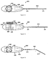
- Figure 12 is a top view showing another example of a stylet device.
- Figure 13 is a side view showing the other example of astylet device.
- Figure 14 is a cross-sectional view showing the stylet of the other example of the stylet device.
- Figure 15 is a view showing the bent condition of the stylet apical end of the stylet device of the other example.
- Figure 1 is a front view showing the entire medical tube assembly of this embodiment.
- the medical tube assembly 1 has an ileus tube 100 as the medical tube and stylet device 200.
- Ileus tube 100 comprises a main tube unit 110 and a guidance member 120 wherein the guidance member 120 is on the apical end of main tube unit 110 (shown on the left side of the drawing).
- the guidance member becomes the leading member and advances into the body cavity, and guides main tube unit 110 to the affected area.
- the main tube unit 110 is a tubular member that follows guidance member 120, within which are formed several lumens that function as corridors when the contents of the affected area are to be drained to the outside, or chemicals are to be supplied to the affected area from the outside, for example.
- balloon 130 has been attached to the circumference of main tube unit 110. This balloon 130 becomes inflated when it receives a supply of fluid from the balloon lumen to be described below, and comes in contact with the inside wall of the small intestines, for example, downstream of the stomach.
- balloon 130 is shown in its inflated condition, but balloon 130 is contracted when ileus tube 100 is inserted into the body cavity.
- the circumference of main tube unit 110 is provided with multiple inlet ports 111.
- the irrigation side hole 112 is provided on the circumference of main tube unit 110 closer to guidance member 120 than to the part where balloon 130 is attached.
- the basal end of main tube unit 110 branches into three branches (the first branch 110a, the second branch 110b, and the third branch 110c).
- the stylet device 200 is provided with a stylet 210 formed in an elongated shape, and a tension-conferring device 220 that is connected to the tip of stylet 210.
- FIG. 2 is a radial cross-section of main tube unit 110 of ileus tube 100.
- a suction lumen 113 is formed, which is a lumen for draining the contents from within the central part of the body to the outside.
- the balloon lumen 114 which in the figure is shown above suction lumen 113, is formed to be a lumen for supplying fluid to balloon 130.
- the irrigation tube 115 which in the figure is shown below suction lumen 113, is formed as a lumen for supplying air to the body cavity in order to prevent negative pressure in the body cavity.
- the irrigation tube 115 is also used to deliver chemicals, such as contrast medium, into the body.
- the suction lumen 113 is formed along the axial direction of main tube unit 110.
- the multiple inlet ports 111 formed on the circumference of main tube unit 110 communicate with suction lumen 113.
- the balloon lumen 114 is formed along the axial direction of main tube unit 110 parallel to suction lumen 113, and communicates with balloon 130.
- the irrigation tube 115 is also formed along the axial direction of main tube unit 110, parallel to suction lumen 113.
- the irrigation side hole 112 formed on the circumference of main tube unit 110 communicates with the irrigation tube 115.
- the suction lumen 113 communicates with the first branch 110a that branches from the basal end of main tube unit 110, balloon lumen 114 communicates with the second branch 110b, and irrigation tube 115 communicates with the third branch 110c.
- valve 110e is connected to the end of second branch 110b.
- the backflow valve 110f is connected to the end of third branch 110c.
- the backflow valve 110f permits fluids to flow from the outside into third branch 110c, but blocks fluids from flowing from third branch 110c to the outside.
- the connector 110d is attached to the end of first branch 110a.
- the stylet 210 of stylet device 200 is inserted into first branch 110a via this connector 110d.
- stylet 210 is formed as an elongated shape with a length that allows for insertion from the apical end of ileus tube 100 towards the posterior end.
- Figure 3 is an axial cross-section showing the vicinity of guidance member 120 of ileus tube 100 when stylet 210 has been inserted.
- guidance member 120 comprises guidance tube member 121, which communicates with main tube unit 110, and weights 122, which are attached so as to cover the periphery of guidance tube member 121.
- the weights 122 present an annular shape in which spheres are perforated by a cylindrical hole.
- a corridor 121 a is formed within guidance tube member 121. One end of corridor 121a communicates with suction lumen 113 of main tube unit 110, and the other end opens to the outside as apical end aperture 121 b of guidance tube member 121.
- the weights 122 (six in this example) are attached, allowing for a predetermined interval along the axial direction of guidance tube member 121.
- the periphery of the weights 122 is covered with a soft resin cover 123, and it is by means of this cover 123 that the axial movement of each weight 122 is regulated, and the weights 122 are fixed in predetermined positions on guidance tube member 121.
- the stylet 210 is inserted into first branch 110a from connector 110d, and then inserted from first branch 110a into suction lumen 113 of main tube unit 110, and into corridor 121a of guidance tube member 121 (cf. Figure 3).
- the stylet 210 has an apical tip 211 and a main unit 212, as shown in Figure 3.
- the apical tip 211 is formed on the apical end of stylet 210, and is the portion that is inserted into corridor 121 a within guidance tube member 121 of ileus tube 100.
- the main unit 212 is the part that follows after apical tip 211, and is inserted into suction lumen 113 of main tube unit 110 of ileus tube 100.
- the apical tip 211 is formed of soft resin (such as soft polyurethane or low-density polyethylene, for example), and main unit 212 is formed of hard resin (such as hard polyurethane or high-density polyethylene, for example). This enables apical tip 211 to bend or deform into a flexion or curve, for example.
- soft resin such as soft polyurethane or low-density polyethylene, for example
- main unit 212 is formed of hard resin (such as hard polyurethane or high-density polyethylene, for example). This enables apical tip 211 to bend or deform into a flexion or curve, for example.
- Figure 4 shows a radial cross-section of stylet 210
- Figure 5 shows an axial cross-section of the vicinity of apical tip 211 of stylet 210.
- stylet 210 is formed such that lumen 213 runs lengthwise through its approximate central region.
- a reinforcing core wire (omitted from the drawings) is inserted into lumen 213.
- reinforcing stylet 210 by inserting a core wire into lumen 213, it is possible to reinforce the stylet by manufacturing the stylet so that a plastic resin covers the core wire.
- stylet 210 has been formed so that multiple (i.e. three in this embodiment) actuator wire lumens 214a, 214b, and 214c (hereinunder collectively referred to in the singular as "actuator wire lumen 214") have been formed so as to surround lumen 213.
- actuator wire lumen 214a, 214b, 214c is formed in a position that is offset from the axial core O of stylet 210.
- the actuator wire lumen 214a, 214b, 214c is formed lengthwise from apical tip 211 of stylet 210 towards main unit 212; at one end it is closed in a position close to leading member 216 of stylet 210, while the other end is open from the basal end of stylet 210 (not shown in the drawing).
- actuator wire 215" corresponding actuator wires 215a, 215b, and 215c have been inserted (hereinunder collectively referred to in the singular as "actuator wire 215").
- each actuator wire 215a, 215b, 215c is thrust through the closed end of actuator wire lumen 214a, 214b, and 214c, and fixed in stylet 210 in a position close to leading member 216 of stylet 210.
- the stylet 210 into which the three actuator wires 215a, 215b, and 215c have been inserted, is connected to the tension-conferring device 220 on the basal end, as shown in Figure 1.
- the tension-conferring device 220 is formed into an elongated shape resembling a ball-point pen.
- Figure 6 is an axial cross-section across the plane that includes the lengthwise axis of tension-conferring device 220.
- Figure 7 is an enlarged cross-section at A-A of Figure 6.
- the tension-conferring device 220 has a main unit 221 formed in a rounded bar shape. Within the main unit 221, three corridors 222 have been formed at equal circumferential intervals.
- windows 223 have been formed, in which slit-shaped sections have been cut out along the axial direction. Three of these windows 223 are formed at equal circumferential intervals, each communicating with a corridor 222, and opposite that corridor 222, thus creating apertures in a fixed portion of each corridor 222 (in Figure 6, the portion is about one-half). The width of each window 223 is narrower than the width of each corridor 222.
- An actuator lever 224 is attached to main unit 221.
- This actuator lever 224 has a guiding member 224a, coupling member 224b, and an actuator member 224c.
- the guiding member 224a is inserted into corridor 222, and is able to move in the axial direction of main unit 221 along corridor 222.
- the coupling member 224b is emplaced vertically on guiding member 224a, extends radially outwards from main unit 221, and projects outwards from window 223.
- the actuator member 224c is connected to the radially projecting portion of coupling member 224b. Accordingly, guiding member 224a is moveable along window 223, and thereby moveable within corridor 222, by operating actuator member 224c with fingers.
- three actuator levers 224 have been provided at circumferentially equal intervals on main unit 221, opposite the three corridors 222.
- the cover 225 has been attached.
- the cover 225 is formed in a bullet shape with a hollow interior, and the end with the larger radius is connected to the end of main unit 221, while the end with the smaller radius forms the aperture 225a.
- the stylet 210 is attached to aperture 225a.
- the actuator wire 215 is inserted through actuator wire lumen 214 of stylet 210, and this actuator wire 215 advances from the basal end of stylet 210 into corridor 222 of main unit 221 via the space within cover 225. Its end is affixed to the guiding member 224a of actuator lever 224.
- actuator wire 215 is affixed to apical tip 211 of stylet 210, and the other end is affixed to actuator lever 224. Accordingly, it is possible to impart tension to actuator wire 215, by sliding actuator member 224c to the right, as shown in Figure 6, with a finger, thus pulling the actuator wire 215. It is also possible to provide an energizing means, such as a spring within corridor 222, to energize actuator lever 224; and it is also possible to position actuator member 224c at the left side of Figure 6 at normal times.
- an energizing means such as a spring within corridor 222
- ileus tube 100 When the treatment or diagnosis of ileus is to be conducted with a medical tube assembly 1 of the structure described above, first a condition is created whereby stylet 210 is inserted into ileus tube 100, as shown in Figure 1, and then ileus tube 100 is inserted transnasally or orally with guidance member 120 as the leading side. Then ileus tube 100 passes through the esophagus and reaches the stomach, and as the next step, it is poised to pass through the stomach via the pyloric ring. At this time, in order to pass through the pyloric ring, the operator operates the actuator lever 224 of the tension-conferring device 220, and actuator member 224c moves in the direction of arrow B in Figure 1.
- each of the three actuator wire lumens 214a, 214b, and 214c formed on stylet 210 is arranged in a position that respectively deviates from the axial core of stylet 210, so the tension from the actuator wire is also transmitted to stylet 210, with some displacement from the center of stylet 210.
- stylet 210 tends to contract biased in the direction of an actuator wire lumen (for example, actuator wire lumen 214a) in which an actuator wire (for example, actuator wire 215a) has been inserted to which tension has been imparted, and thus it bends in this direction.
- actuator wire lumen for example, actuator wire lumen 214a
- actuator wire for example, actuator wire 215a
- the apical tip 211 of stylet 210 has been formed of soft resin, and the main unit 212 following apical tip 211 has been formed of hard resin, so apical tip 211 is less rigid than main unit 212. Therefore, only apical tip 211 of stylet 210 bends, as shown in Figure 8, due to the aforementioned tension. Because apical tip 211 is bent, as shown in Figure 9, the guidance member 120 of ileus tube 100 in which apical tip 211 has been inserted is bent similarly to apical tip 211.
- Figure 10 is an axial cross-section of the vicinity of guidance member 120 of ileus tube 100.
- the apical tip 211 of stylet 210 curves so as to bend to the side formed by actuator wire lumen 214 in which has been inserted actuator wire 215, to which tension has been imparted.
- stylet 210 bends, its apical tip 211 comes into contact with the inner wall of corridor 121a formed in guidance tube member 121 of ileus tube 100, imparting a bending force to ileus tube 100 as well, and thus guidance member 120 of ileus tube 100 is bent.
- guidance member 120 is bent in the desired direction, and thus the apical end of guidance member 120 faces the direction of the pyloric ring.
- ileus tube 100 is caused to progress further, and is caused to pass through the pyloric ring. Thereafter, byrepeatedly conducting operations identical to those described above, the ileus tube 100 passes through portions having curved passageways, such as Treitz's ligament, for example, and progresses to the small intestine.
- the actuator lever 224 for manipulation is changed to correspond to the curvature orientation.
- main tube unit 110 of ileus tube 100 When main tube unit 110 of ileus tube 100 reaches the small intestine, for example, the stylet 210 is withdrawn from ileus tube 100. Fluid is supplied from second branch 110b to balloon lumen 114. Then the fluid passes through balloon lumen 114 and is supplied to balloon 130. Balloon 130 becomes enlarged, and comes into contact with the inner wall of the small intestine, for example. The peristaltic movement of the small intestine, for example, is transmitted to balloon 130, and ileus tube 100 then progresses in the small intestine, for example, by the peristaltic movement of the small intestine, for example. Then, the ileus tube 100 progresses to the desired location.
- a suction bag is connected to first branch 110a.
- the suction bag is operated, and the inside of suction lumen 113 is depressurized.
- the contents of the small intestines for example, are taken into suction lumen 113 from apical end aperture 121 b of guidance tube member 121 and inlet ports 111 of main tube unit 110.
- the contents thus taken in pass from suction lumen 113 through first branch 110a and are recovered in the suction bag. In this way, an ileus, for example, is treated.
- FIG 11 is a drawing showing a different example for the structure of the ileus tube guidance member.
- a spring 124 is provided inside guidance tube member 121.
- Such a structure makes it possible to give more elasticity to guidance tube member 121, and thus enables flexible bending of the entire body of guidance tube member 121.
- FIG 12 is a top view of another example of the stylet device
- Figure 13 is a side view.
- This stylet device 300 has a tension-conferring device 320 provided with two rotatable actuator levers (first actuator lever 321, and second actuator lever 322).
- the first and second actuator levers 321 and 322 are attached one above the other such that they share the same axis of rotation.
- the first actuator lever 321 is linked to first disk plate 325 positioned within main unit 330, via first connecting shaft 323, and is structured with first connecting shaft 323 as the axis, so as to rotate as an integrated unit with first disk plate 325.
- the second actuator lever 322 is linked to second disk plate 326 positioned within main unit 330, via second connecting cylinder 324, and is structured with second connecting cylinder 324 representing the axis to rotate as an integrated unit with second disk plate 326.
- the second actuator lever 322, second connecting cylinder 324, and the second disk plate 326 are interpolated with first connecting shaft 323, and this assembly is structured to be disposed with first connecting shaft 323 representing the axis. It is possible to permit mutually independent rotation of both plates by, for example, disposing bearings and the like between first disk plate 325 and second disk plate 326.
- the stylet 310 has an apical tip 311 formed of soft resin and a main unit 312 formed of hard resin; the main unit 330 of tension-conferring device 320 is attached to the basal end of main unit 312.
- a radial cross-section of stylet 310 is shown in Figure 14.
- lumen 313, into which a reinforcing core wire (omitted from the drawing) is inserted, is formed in the cross-sectional center of stylet 310, and four actuator wire lumens are formed at 90° intervals on the circumference of lumen 313.
- the actuator wire lumen formed on the right side of the drawing is right lumen 314r
- the actuator wire lumen formed on the left side is left lumen 314l
- the actuator wire lumen formed on the top side is upper lumen 314u
- the actuator wire lumen formed on the lower side is lower lumen 314d.
- the actuator wire lumen 314d, 3141, 314r, 314u is formed along the axial orientation of stylet 310 from apical tip 311 towards main unit 312.
- the actuator wires 315r, 3151, 315u, and 315d have been inserted into actuator wire lumens 314r, 3141, 314u, and 314d.
- actuator wire 315r, 3151, 315u, 315d is affixed to apical tip 311 of stylet 310 and passes insertionally through actuator wire lumen 314d, 314l, 314r, 314u, and the other end is affixed to first disk plate 325 or second disk plate 326.
- actuator wires 315r, 3151, 315u, 315d Attached to disk plates 325 and 326, seen from the radial cross-section of stylet 310 ( Figure 14), are the ends of actuator wires 315r, 3151, 315u, 315d, which are inserted into lumens 314d, 3141, 314r, 314u, in positions opposite lumen 313.
- actuator wires 315r and 3151 inserted into right lumen 314r and left lumen 3141 may be affixed to first disk plate 325
- actuator wires 315u and 315d inserted into upper lumen 314u and lower lumen 314d may be affixed to second disk plate 326.
- the actuator wires 315r, 315l, 315u, 315d are affixed to disk plates 325 and 326 such that, when disk plate 325 or 326 is rotated in a single direction, one of the actuator wires 315 will be pulled, and if it is rotated in the other direction, the other actuator wire 315 will pulled.
- first actuator lever 321 when first actuator lever 321 is rotationally manipulated, tension will be imparted to either the actuator wire 315r or actuator wire 315l inserted into right lumen 314r or left lumen 3141, and the apical tip 311 of stylet 310 will bend in the left or right direction (cf. Figure 15).
- second actuator lever 322 is rotationally manipulated, tension will be imparted to either the actuator wire 315u or actuator wire 315d inserted into upper lumen 314u or lower lumen 314d, and the apical tip 311 of stylet 310 will bend in the upward or downward direction.
- the first and second actuator levers 321 and 322 are simultaneously rotationally manipulated, it is possible to bend the apical end of stylet 310 towards the upper left, or towards the lower right.
- stylet devices 200 and 300 of the present embodiments are formed in an elongated shape, and are capable of bending deformation; they are furnished with stylets 210 and 310 in which are formed actuator wire lumens 214a, 214b, 214c and 314d, 314l, 314r, 314u along the axial direction in positions that are radially offset from the internal axial cores; with actuator wires 215a, 215b, 215c and 315r, 3151, 315u, 315d that are inserted into actuator wire lumens 214a, 214b, and 214c and 314d, 3141, 314r, 314u, having one end affixed to the apical tips 211 and 311 of stylets 210 and 310; and with tension-conferring devices 220 and 320 that impart tension to actuator wires 215a, 215b, 215c, and 315r, 3151, 315u, 315d and that are connected to the other ends
- the apical tips 211 and 311 of stylets 210 and 310 are structured so as to actively bend according to the operation of tension-conferring devices 220 and 320. This makes it possible to actively bend the guidance member 120 of ileus tube 100, into which stylets 210 and 310 have been inserted. Accordingly, it is possible to easily pass ileus tube 100 through even complex passages in the body cavity.
- the apical tip 211 is formed from a soft resin, whereas the main unit 212 is formed from a hard resin, so apical tip 211 is not as hard as main unit 212. This allows bending or deformation of only apical tip 211. Since only the apical tip 211 of stylet 210 is bent, it is possible to bend only the guidance member 120 of ileus tube 100 in which apical tip 211 is inserted.
- apical tip 211 was less rigid than main unit 212 of stylet 210, in order that only the guidance member 120 of ileus tube 100 would bend, but it is also possible for guidance member 120 of ileus tube 100 to be less rigid than main tube unit 110 in order for only the guidance member 120 to bend.
- guidance tube member 121 may be formed from a soft resin
- main tube unit 110 may be formed from a hard resin, thus making it possible for guidance member 120 to be less rigid than main tube unit 110.
- guidance tube member 121 and main tube unit 110 out of the same material, but for the external diameter of guidance tube member 121 to be smaller than that of main tube unit 110, and thereby for guidance member 120 to be less rigid than main tube unit 110.
- the apical tip 211 in order for apical tip 211 to be less rigid than the main unit 212 of stylet 210, the apical tip 211 was formed of a soft resin while main unit 212 was formed of a hard resin, but it is also possible for the apical tip 211 to be less rigid than main unit 212 by using other materials.
- apical tip 211 is smaller than the external diameter of main unit 212, so that apical tip 211 is less rigid than main unit 212.
- the diameter of the core wire that is inserted into the portion of lumen 213 formed within apical tip 211 may be made smaller than the diameter of the core wire that is inserted into the portion that is formed within main unit 212, and thus the rigidity of apical tip 211 will be less than that of main unit 212.
Abstract
Description
- The present invention pertains to a stylet device and a medical tube assembly in which the stylet is inserted into a medical tube.
- A large variety of tubes in the way of medical tubes is available to be inserted into the living body. These are called ileus tubes, which are tubes used for diagnosis and therapy of enterostasis. An ileus tube is inserted transnasally or orally until it reaches the appropriate position in the small intestine, for example, and is used to reduce pressure inside the patient, suction out contents, or inject chemicals such as contrast media, for example. Before reaching the small intestines, for example, the ileus tube must pass through the pyloric ring and Treitz's ligament. Because these areas are curved and narrow, it is not easy for the ileus tube to pass through them. In particular, if the rigidity of the ileus tube is low, sometimes when it passes through the pyloric ring its apical end will abut the stomach wall and bend, thus coiling up within the stomach. Therefore, it has been proposed to insert a stylet into the ileus tube, to increase the rigidity of the tube and allow it to advance through complex passages.
- In
Japanese Kokai Utility Model No. Sho 63[1988]-77055 Japanese Kokoku Patent No. 2000-217926 - The present invention refers to a conventional medical tube assembly wherein a stylet is inserted so that the rigidity of the medical tube is increased by the rigidity of the stylet., In consequence, the medical tube does not easily bend even in complex passages, thus allowing advancement of the medical tube within passages. However, in the more complex passages, such as the passages in the vicinity of the pyloric ring and Treitz's ligament mentioned above, the medical tube cannot follow the curvature of passages merely by imparting rigidity to the medical tube by a stylet. Here, the medical tube assembly described in
Japanese Kokai Utility Model No. Sho 63[1988]-77055 - In view of the situation described above, the objective of the present invention is to offer a stylet device to allow easy advancement of a medical tube through complex passages, and a medical tube assembly that has a medical tube with the stylet inserted.
- In order to accomplish the objective described above, the stylet device of the present invention is characterized in that it comprises a stylet that is formed in an elongated shape and is suitable to bend or deform, and for which an actuator wire lumen has been formed along the axial direction in a position that is radially biased from the internal axial core, and an actuator wire that is inserted into the aforementioned actuator wire lumen, one end of which is affixed to the aforementioned stylet, and a tension-conferring means that is connected to the other end of the aforementioned actuator wire and that imparts tension to the aforementioned actuator wire. The medical tube assembly of the present invention is characterized in that it comprises a stylet device having the structure described above, and with a medical tube, such as an ileus tube, into which the stylet of the stylet device is inserted.
- In the aforementioned inventive stylet device, when the tension-conferring means imparts tension to the actuator wire, this tension is transmitted to the stylet to which the actuator wire is affixed. The tension is transmitted to a position deflected from the axial core of the stylet, because the actuator wire lumen, through which the actuator wire has been inserted, has been formed along the axial direction (lengthwise) of the stylet, and also because it has been formed in a position that is radially biased from the axial core of the stylet. Therefore, the stylet bends in the direction in which the actuator wire lumen through which the actuator wire is inserted, has been deflected. Accordingly, by inserting this kind of stylet into a medical tube, the medical tube bends according to the above-described bending of the stylet. In this way, not only does the invented stylet device provide rigidity to the medical tube, but it also enables active bending of the medical tube. Thus it is possible for the apical end of the medical tube to be deflected with the curvature of the passage, which enables passage of the medical tube through even complex passages.
- The inventive stylet is formed of any material, that is suitable to bend or deform. This "bending deformation" is by any bending method, such as flexure, bending, and curving, for example, as long as the axial core of the stylet deforms into a condition other than that of a straight line. It is sufficient, if only part of the stylet is bendable or deformable, even if the entire stylet is not bendable or deformable.
- The inventive stylet device is also characterized in that multiple aforementioned actuator wire lumens are formed in the aforementioned stylet, and the aforementioned actuator wires are inserted through at least two of the multiple aforementioned actuator wire lumens. This enables bending of the stylet in the various directions in which the multiple actuator wires have respectively been imparted with tension. A suitable number of actuator wire lumens through which actuator wires may be inserted is 2-4, formed at intervals of 80°-180° around the circumference of the stylet; they are also formed at equal intervals. In this case, by manipulating multiple actuator wires simultaneously, it is possible to adjust the curvature direction of the stylet and bend the stylet in more directions.
- When multiple actuator wires are used, the other end of each actuator wire is connected to a single tension-conferring means. The use of a single tension-conferring means (device) is convenient because this enables pulling and manipulating of the respective actuator wires and thus imparting of tension to them. In this case, the tension-conferring means are structured similar to a multicolor ballpoint pen, for example, or it is structured so that individual actuator levers are individually connected to respective actuator wires; alternatively, the tension-conferring means are characterized in that all the actuator wires are connected to a single actuator lever, and this actuator lever, like a joystick, is freely deflected off-center, thus adjusting the tensile status of the actuator wires.
- The inventive stylet is also structured so that it is furnished with an apical end to which one end of the aforementioned actuator wire is affixed, and a main unit that is connected to the aforementioned apical end, with the aforementioned apical end being less rigid than the aforementioned main unit. This makes it possible to bend only the apical end of the stylet when tension is applied to the actuator wire. In order to obtain an apical end that is less rigid than the main unit, the apical end is formed from a softer material than the main unit. For example, a stylet for which only the apical end bends are realized if the apical end is formed of a soft resin and the main unit of a hard resin. When identical material is used for the entire unit, it is still possible to actualize a stylet for which only the apical end bends by causing the outer radius of the apical end to be smaller than that of the main unit, thus lowering the rigidity of the apical end. When bringing about a structure such that only the apical end bends by causing a difference in rigidity or hardness between the apical end portion ("apical end") and the other portions ("main unit") of the stylet, as mentioned above, it is possible for the actuator wire lumen to be formed from the apical end of the stylet towards the main unit.
- Another characteristic of the inventive medical tube assembly is the structure whereby the stylet that is inserted into the medical tube is furnished with an apical end to which one end of the aforementioned actuator wire is affixed, and with a main unit that is connected to the aforementioned apical end; the aforementioned medical tube comprises a main tube unit into which the aforementioned main unit is inserted, and with a guidance member that guides the aforementioned main tube unit into cavities within the body, and into which the aforementioned apical end is inserted, such that when tension is imparted to the aforementioned actuator wire by the aforementioned tension-conferring means, the aforementioned guidance member is bent. This structure, wherein the apical end portion (guidance member) of the medical tube is bent, enables smooth passage through narrow and complex passages.
- In this case, the guidance member of the medical tube is structured to be less rigid than the main tube unit, thus making it possible for only the guidance member to be bent. For example, if the hardness of the guidance member of the medical tube is less than that of the main tube unit, it is possible for only the guidance member of the medical tube to be bent. Alternatively, by means of a structure whereby the apical end of the stylet inserted into the medical tube is less rigid than the main unit, it is possible to bend only the guidance member.
- With regard to the invented medical tube assembly, multiple lumens are formed within the medical tube, a balloon is attached to its periphery, and a weight is attached to the guidance member.
- Figure 1 is a general view of a medical tube assembly of an embodiment of the present invention.
Figure 2 is a cross-sectional view of a main tube unit of the ileus tube of an embodiment of the present invention.
Figure 3 is a longitudinal sectional view of the vicinity of a guidance member of the ileus tube of an embodiment of the present invention.
Figure 4 is a cross-sectional view of a stylet of an embodiment of the present invention.
Figure 5 is a longitudinal sectional view of the vicinity of an apical end of a stylet of an embodiment of the present invention.
Figure 6 is a longitudinal sectional view of a tension-conferring device of an embodiment of the present invention.
Figure 7 is a cross-section at A-A of Figure 6.
Figure 8 is a view showing the condition wherein the apical end of a stylet is bent.
Figure 9 is a view showing the condition wherein the guidance member of an ileus tube is bent.
Figure 10 is a longitudinal sectional view showing the condition wherein the guidance member of an ileus tube is bent.
Figure 11 is a view showing another example of the guidance member of an ileus tube.
Figure 12 is a top view showing another example of a stylet device.
Figure 13 is a side view showing the other example of astylet device.
Figure 14 is a cross-sectional view showing the stylet of the other example of the stylet device.
Figure 15 is a view showing the bent condition of the stylet apical end of the stylet device of the other example. - The following statements explain the stylet device and medical tube assembly of the present invention using drawings. Figure 1 is a front view showing the entire medical tube assembly of this embodiment. The medical tube assembly 1 has an
ileus tube 100 as the medical tube andstylet device 200.Ileus tube 100 comprises amain tube unit 110 and aguidance member 120 wherein theguidance member 120 is on the apical end of main tube unit 110 (shown on the left side of the drawing). Whenileus tube 100 is inserted into body cavities transnasally or orally, the guidance member becomes the leading member and advances into the body cavity, and guidesmain tube unit 110 to the affected area. Themain tube unit 110 is a tubular member that followsguidance member 120, within which are formed several lumens that function as corridors when the contents of the affected area are to be drained to the outside, or chemicals are to be supplied to the affected area from the outside, for example. In the left portion of the drawing,balloon 130 has been attached to the circumference ofmain tube unit 110. Thisballoon 130 becomes inflated when it receives a supply of fluid from the balloon lumen to be described below, and comes in contact with the inside wall of the small intestines, for example, downstream of the stomach. In the drawing,balloon 130 is shown in its inflated condition, butballoon 130 is contracted whenileus tube 100 is inserted into the body cavity. - The circumference of
main tube unit 110 is provided withmultiple inlet ports 111. Theirrigation side hole 112 is provided on the circumference ofmain tube unit 110 closer toguidance member 120 than to the part whereballoon 130 is attached. The basal end ofmain tube unit 110 branches into three branches (thefirst branch 110a, thesecond branch 110b, and thethird branch 110c). Thestylet device 200 is provided with astylet 210 formed in an elongated shape, and a tension-conferringdevice 220 that is connected to the tip ofstylet 210. Whenileus tube 100 is inserted into a body cavity,stylet 210 is inserted intoileus tube 100 viafirst branch 110a as shown in the drawing, and increases the rigidity ofileus tube 100. - Figure 2 is a radial cross-section of
main tube unit 110 ofileus tube 100. As shown in Figure 2, withinmain tube unit 110 asuction lumen 113 is formed, which is a lumen for draining the contents from within the central part of the body to the outside. Theballoon lumen 114, which in the figure is shown abovesuction lumen 113, is formed to be a lumen for supplying fluid toballoon 130. Theirrigation tube 115, which in the figure is shown belowsuction lumen 113, is formed as a lumen for supplying air to the body cavity in order to prevent negative pressure in the body cavity. Theirrigation tube 115 is also used to deliver chemicals, such as contrast medium, into the body. Thesuction lumen 113 is formed along the axial direction ofmain tube unit 110. Themultiple inlet ports 111 formed on the circumference ofmain tube unit 110 communicate withsuction lumen 113. Theballoon lumen 114 is formed along the axial direction ofmain tube unit 110 parallel tosuction lumen 113, and communicates withballoon 130. Theirrigation tube 115 is also formed along the axial direction ofmain tube unit 110, parallel tosuction lumen 113. Theirrigation side hole 112 formed on the circumference ofmain tube unit 110 communicates with theirrigation tube 115. - The
suction lumen 113 communicates with thefirst branch 110a that branches from the basal end ofmain tube unit 110,balloon lumen 114 communicates with thesecond branch 110b, andirrigation tube 115 communicates with thethird branch 110c. As shown in Figure 1,valve 110e is connected to the end ofsecond branch 110b. Thebackflow valve 110f is connected to the end ofthird branch 110c. Thebackflow valve 110f permits fluids to flow from the outside intothird branch 110c, but blocks fluids from flowing fromthird branch 110c to the outside. Theconnector 110d is attached to the end offirst branch 110a. Thestylet 210 ofstylet device 200 is inserted intofirst branch 110a via thisconnector 110d. As can be understood from Figure 1,stylet 210 is formed as an elongated shape with a length that allows for insertion from the apical end ofileus tube 100 towards the posterior end. - Figure 3 is an axial cross-section showing the vicinity of
guidance member 120 ofileus tube 100 whenstylet 210 has been inserted. As shown in Figure 3,guidance member 120 comprisesguidance tube member 121, which communicates withmain tube unit 110, andweights 122, which are attached so as to cover the periphery ofguidance tube member 121. Theweights 122 present an annular shape in which spheres are perforated by a cylindrical hole. Acorridor 121 a is formed withinguidance tube member 121. One end ofcorridor 121a communicates withsuction lumen 113 ofmain tube unit 110, and the other end opens to the outside asapical end aperture 121 b ofguidance tube member 121. The weights 122 (six in this example) are attached, allowing for a predetermined interval along the axial direction ofguidance tube member 121. The periphery of theweights 122 is covered with asoft resin cover 123, and it is by means of thiscover 123 that the axial movement of eachweight 122 is regulated, and theweights 122 are fixed in predetermined positions onguidance tube member 121. - The
stylet 210 is inserted intofirst branch 110a fromconnector 110d, and then inserted fromfirst branch 110a intosuction lumen 113 ofmain tube unit 110, and intocorridor 121a of guidance tube member 121 (cf. Figure 3). Thestylet 210 has anapical tip 211 and amain unit 212, as shown in Figure 3. Theapical tip 211 is formed on the apical end ofstylet 210, and is the portion that is inserted intocorridor 121 a withinguidance tube member 121 ofileus tube 100. Themain unit 212 is the part that follows afterapical tip 211, and is inserted intosuction lumen 113 ofmain tube unit 110 ofileus tube 100. Theapical tip 211 is formed of soft resin (such as soft polyurethane or low-density polyethylene, for example), andmain unit 212 is formed of hard resin (such as hard polyurethane or high-density polyethylene, for example). This enablesapical tip 211 to bend or deform into a flexion or curve, for example. - Figure 4 shows a radial cross-section of
stylet 210, and, Figure 5 shows an axial cross-section of the vicinity ofapical tip 211 ofstylet 210. As shown in Figures 4 and 5,stylet 210 is formed such thatlumen 213 runs lengthwise through its approximate central region. A reinforcing core wire (omitted from the drawings) is inserted intolumen 213. In addition to reinforcingstylet 210 by inserting a core wire intolumen 213, it is possible to reinforce the stylet by manufacturing the stylet so that a plastic resin covers the core wire. - As shown in Figure 4,
stylet 210 has been formed so that multiple (i.e. three in this embodiment)actuator wire lumens actuator wire lumen 214") have been formed so as to surroundlumen 213. Eachactuator wire lumen stylet 210. As shown in Figure 5, theactuator wire lumen apical tip 211 ofstylet 210 towardsmain unit 212; at one end it is closed in a position close to leadingmember 216 ofstylet 210, while the other end is open from the basal end of stylet 210 (not shown in the drawing). Within eachactuator wire lumen actuator wires actuator wire 215"). As shown in Figure 5, one end of eachactuator wire actuator wire lumen stylet 210 in a position close to leadingmember 216 ofstylet 210. - The
stylet 210, into which the threeactuator wires device 220 on the basal end, as shown in Figure 1. In the present embodiment, the tension-conferringdevice 220 is formed into an elongated shape resembling a ball-point pen. Figure 6 is an axial cross-section across the plane that includes the lengthwise axis of tension-conferringdevice 220. Figure 7 is an enlarged cross-section at A-A of Figure 6. As shown in these drawings, the tension-conferringdevice 220 has amain unit 221 formed in a rounded bar shape. Within themain unit 221, threecorridors 222 have been formed at equal circumferential intervals. On the periphery ofmain unit 221,windows 223 have been formed, in which slit-shaped sections have been cut out along the axial direction. Three of thesewindows 223 are formed at equal circumferential intervals, each communicating with acorridor 222, and opposite thatcorridor 222, thus creating apertures in a fixed portion of each corridor 222 (in Figure 6, the portion is about one-half). The width of eachwindow 223 is narrower than the width of eachcorridor 222. - An
actuator lever 224 is attached tomain unit 221. Thisactuator lever 224 has a guidingmember 224a,coupling member 224b, and anactuator member 224c. The guidingmember 224a is inserted intocorridor 222, and is able to move in the axial direction ofmain unit 221 alongcorridor 222. Thecoupling member 224b is emplaced vertically on guidingmember 224a, extends radially outwards frommain unit 221, and projects outwards fromwindow 223. Theactuator member 224c is connected to the radially projecting portion ofcoupling member 224b. Accordingly, guidingmember 224a is moveable alongwindow 223, and thereby moveable withincorridor 222, by operatingactuator member 224c with fingers. Note that threeactuator levers 224 have been provided at circumferentially equal intervals onmain unit 221, opposite the threecorridors 222. - As shown in Figure 6, at the apical end of
main unit 221, thecover 225 has been attached. Thecover 225 is formed in a bullet shape with a hollow interior, and the end with the larger radius is connected to the end ofmain unit 221, while the end with the smaller radius forms theaperture 225a. Thestylet 210 is attached toaperture 225a. Theactuator wire 215 is inserted throughactuator wire lumen 214 ofstylet 210, and thisactuator wire 215 advances from the basal end ofstylet 210 intocorridor 222 ofmain unit 221 via the space withincover 225. Its end is affixed to the guidingmember 224a ofactuator lever 224. Therefore, one end ofactuator wire 215 is affixed toapical tip 211 ofstylet 210, and the other end is affixed toactuator lever 224. Accordingly, it is possible to impart tension toactuator wire 215, by slidingactuator member 224c to the right, as shown in Figure 6, with a finger, thus pulling theactuator wire 215. It is also possible to provide an energizing means, such as a spring withincorridor 222, to energizeactuator lever 224; and it is also possible to positionactuator member 224c at the left side of Figure 6 at normal times. - When the treatment or diagnosis of ileus is to be conducted with a medical tube assembly 1 of the structure described above, first a condition is created whereby
stylet 210 is inserted intoileus tube 100, as shown in Figure 1, and thenileus tube 100 is inserted transnasally or orally withguidance member 120 as the leading side. Thenileus tube 100 passes through the esophagus and reaches the stomach, and as the next step, it is poised to pass through the stomach via the pyloric ring. At this time, in order to pass through the pyloric ring, the operator operates theactuator lever 224 of the tension-conferringdevice 220, andactuator member 224c moves in the direction of arrow B in Figure 1. This then causes theactuator wire 215, being affixed to the manipulatedactuator lever 224, to be pulled. Therefore, the pulledactuator wire 215 becomes tense, and thus tension is imparted toactuator wire 215. This tension is transferred tostylet 210, which is affixed to one end ofactuator wire 215. Here, as shown in Figure 4, each of the threeactuator wire lumens stylet 210 is arranged in a position that respectively deviates from the axial core ofstylet 210, so the tension from the actuator wire is also transmitted tostylet 210, with some displacement from the center ofstylet 210. Therefore,stylet 210 tends to contract biased in the direction of an actuator wire lumen (for example,actuator wire lumen 214a) in which an actuator wire (for example,actuator wire 215a) has been inserted to which tension has been imparted, and thus it bends in this direction. - Here, the
apical tip 211 ofstylet 210 has been formed of soft resin, and themain unit 212 followingapical tip 211 has been formed of hard resin, soapical tip 211 is less rigid thanmain unit 212. Therefore, onlyapical tip 211 ofstylet 210 bends, as shown in Figure 8, due to the aforementioned tension. Becauseapical tip 211 is bent, as shown in Figure 9, theguidance member 120 ofileus tube 100 in whichapical tip 211 has been inserted is bent similarly toapical tip 211. Figure 10 is an axial cross-section of the vicinity ofguidance member 120 ofileus tube 100. As shown in Figure 10, theapical tip 211 ofstylet 210 curves so as to bend to the side formed byactuator wire lumen 214 in which has been insertedactuator wire 215, to which tension has been imparted. Asstylet 210 bends, itsapical tip 211 comes into contact with the inner wall ofcorridor 121a formed inguidance tube member 121 ofileus tube 100, imparting a bending force toileus tube 100 as well, and thusguidance member 120 ofileus tube 100 is bent. By means of this operation,guidance member 120 is bent in the desired direction, and thus the apical end ofguidance member 120 faces the direction of the pyloric ring. In thiscondition ileus tube 100 is caused to progress further, and is caused to pass through the pyloric ring. Thereafter, byrepeatedly conducting operations identical to those described above, theileus tube 100 passes through portions having curved passageways, such as Treitz's ligament, for example, and progresses to the small intestine. When the curvature orientation of the passage changes whileileus tube 100 is progressing through the curved passageways, theactuator lever 224 for manipulation is changed to correspond to the curvature orientation. By manipulating twoactuator levers 224 simultaneously, it is possible to bendguidance member 120 in a direction intermediate to the flexure directions when lever is manipulated by itself. - When
main tube unit 110 ofileus tube 100 reaches the small intestine, for example, thestylet 210 is withdrawn fromileus tube 100. Fluid is supplied fromsecond branch 110b toballoon lumen 114. Then the fluid passes throughballoon lumen 114 and is supplied toballoon 130.Balloon 130 becomes enlarged, and comes into contact with the inner wall of the small intestine, for example. The peristaltic movement of the small intestine, for example, is transmitted toballoon 130, andileus tube 100 then progresses in the small intestine, for example, by the peristaltic movement of the small intestine, for example. Then, theileus tube 100 progresses to the desired location. - Once the
ileus tube 100 has progressed to the target location, a suction bag is connected tofirst branch 110a. The suction bag is operated, and the inside ofsuction lumen 113 is depressurized. Then the contents of the small intestines, for example, are taken intosuction lumen 113 fromapical end aperture 121 b ofguidance tube member 121 andinlet ports 111 ofmain tube unit 110. The contents thus taken in pass fromsuction lumen 113 throughfirst branch 110a and are recovered in the suction bag. In this way, an ileus, for example, is treated. - Figure 11 is a drawing showing a different example for the structure of the ileus tube guidance member. In this medical tube, a
spring 124 is provided insideguidance tube member 121. Such a structure makes it possible to give more elasticity toguidance tube member 121, and thus enables flexible bending of the entire body ofguidance tube member 121. - Figure 12 is a top view of another example of the stylet device, and Figure 13 is a side view. This
stylet device 300 has a tension-conferringdevice 320 provided with two rotatable actuator levers (first actuator lever 321, and second actuator lever 322). The first and second actuator levers 321 and 322 are attached one above the other such that they share the same axis of rotation. As shown in Figure 13, thefirst actuator lever 321 is linked tofirst disk plate 325 positioned withinmain unit 330, via first connectingshaft 323, and is structured with first connectingshaft 323 as the axis, so as to rotate as an integrated unit withfirst disk plate 325. Thesecond actuator lever 322 is linked tosecond disk plate 326 positioned withinmain unit 330, via second connectingcylinder 324, and is structured with second connectingcylinder 324 representing the axis to rotate as an integrated unit withsecond disk plate 326. Thesecond actuator lever 322, second connectingcylinder 324, and thesecond disk plate 326 are interpolated with first connectingshaft 323, and this assembly is structured to be disposed with first connectingshaft 323 representing the axis. It is possible to permit mutually independent rotation of both plates by, for example, disposing bearings and the like betweenfirst disk plate 325 andsecond disk plate 326. - The
stylet 310 has anapical tip 311 formed of soft resin and amain unit 312 formed of hard resin; themain unit 330 of tension-conferringdevice 320 is attached to the basal end ofmain unit 312. A radial cross-section ofstylet 310 is shown in Figure 14. As shown in Figure 14,lumen 313, into which a reinforcing core wire (omitted from the drawing) is inserted, is formed in the cross-sectional center ofstylet 310, and four actuator wire lumens are formed at 90° intervals on the circumference oflumen 313. In the present embodiment, the actuator wire lumen formed on the right side of the drawing isright lumen 314r, the actuator wire lumen formed on the left side is left lumen 314l, the actuator wire lumen formed on the top side isupper lumen 314u, and the actuator wire lumen formed on the lower side is lower lumen 314d. Theactuator wire lumen stylet 310 fromapical tip 311 towardsmain unit 312. Theactuator wires actuator wire lumens actuator wire apical tip 311 ofstylet 310 and passes insertionally throughactuator wire lumen first disk plate 325 orsecond disk plate 326. - Attached to
disk plates actuator wires lumens lumen 313. For example,actuator wires right lumen 314r and leftlumen 3141 may be affixed tofirst disk plate 325, andactuator wires upper lumen 314u and lower lumen 314d may be affixed tosecond disk plate 326. Theactuator wires disk plates disk plate - Given the structure, described above, when
first actuator lever 321 is rotationally manipulated, tension will be imparted to either theactuator wire 315r or actuator wire 315l inserted intoright lumen 314r or leftlumen 3141, and theapical tip 311 ofstylet 310 will bend in the left or right direction (cf. Figure 15). On the other hand, ifsecond actuator lever 322 is rotationally manipulated, tension will be imparted to either theactuator wire 315u oractuator wire 315d inserted intoupper lumen 314u or lower lumen 314d, and theapical tip 311 ofstylet 310 will bend in the upward or downward direction. If, on the other hand the first and second actuator levers 321 and 322 are simultaneously rotationally manipulated, it is possible to bend the apical end ofstylet 310 towards the upper left, or towards the lower right. - As explained above,
stylet devices stylets actuator wire lumens actuator wires actuator wire lumens apical tips stylets devices actuator wires actuator wires apical tips stylets devices guidance member 120 ofileus tube 100, into whichstylets ileus tube 100 through even complex passages in the body cavity. - As for
stylet 210, theapical tip 211 is formed from a soft resin, whereas themain unit 212 is formed from a hard resin, soapical tip 211 is not as hard asmain unit 212. This allows bending or deformation of onlyapical tip 211. Since only theapical tip 211 ofstylet 210 is bent, it is possible to bend only theguidance member 120 ofileus tube 100 in whichapical tip 211 is inserted. - The foregoing statements have described working modes of the present invention, but the present invention is not limited to these embodiments. For example, in the aforementioned embodiment,
apical tip 211 was less rigid thanmain unit 212 ofstylet 210, in order that only theguidance member 120 ofileus tube 100 would bend, but it is also possible forguidance member 120 ofileus tube 100 to be less rigid thanmain tube unit 110 in order for only theguidance member 120 to bend. In this case,guidance tube member 121 may be formed from a soft resin, andmain tube unit 110 may be formed from a hard resin, thus making it possible forguidance member 120 to be less rigid thanmain tube unit 110. It is also possible to formguidance tube member 121 andmain tube unit 110 out of the same material, but for the external diameter ofguidance tube member 121 to be smaller than that ofmain tube unit 110, and thereby forguidance member 120 to be less rigid thanmain tube unit 110. Also, in the aforementioned embodiment, in order forapical tip 211 to be less rigid than themain unit 212 ofstylet 210, theapical tip 211 was formed of a soft resin whilemain unit 212 was formed of a hard resin, but it is also possible for theapical tip 211 to be less rigid thanmain unit 212 by using other materials. It is also possible by means other than changing the material, for example, by changing the shape that the external diameter ofapical tip 211 is smaller than the external diameter ofmain unit 212, so thatapical tip 211 is less rigid thanmain unit 212. Also with regard to the provision oflumen 213 close to the center ofstylet 210 and the insertion of a core wire within thislumen 213, the diameter of the core wire that is inserted into the portion oflumen 213 formed withinapical tip 211 may be made smaller than the diameter of the core wire that is inserted into the portion that is formed withinmain unit 212, and thus the rigidity ofapical tip 211 will be less than that ofmain unit 212.
Claims (8)
- A stylet device (200, 300) characterized in that the device comprises:a deformable stylet (210, 310) having an elongated shape and being provided with an actuator wire lumen (214, 214a, 214b, 214c, 314) extending in an axial direction in a position that is radially off-center with respect to a cross section of said stylet;an actuator wire (215, 215a, 215b, 215c, 315) inserted into the actuator wire lumen, wherein one end of said actuator wire is affixed to the stylet, anda tension-conferring means (220, 320) connected to another end of the actuator wire for imparting tension to the actuator wire.
- A stylet device (200, 300) according to Claim 1, characterized in that multiple actuator wire lumens (214, 214a, 214b, 214c, 314) are formed in the stylet (210, 310), and actuator wires (215, 215a, 215b, 215c, 315) are inserted into two or more of the multiple actuator wire lumens.
- A stylet device (200, 300) according to Claim 1 or 2, characterized in that the stylet (210, 310) comprises a distal end part to which one end of the actuator wire (215, 215a, 215b, 215c, 315) is affixed, and a main part (212, 312) that is connected to the distal end part, wherein the distal end part is less rigid than the main part.
- A medical tube assembly (1) comprising a stylet device (200, 300) according to any of Claims 1 to 3 and a medical tube (100) having an interior into which the stylet (210, 310) of the stylet device is inserted.
- A medical tube assembly (1) according to Claim 4, characterized in that the medical tube (100) comprises a main tube unit (110) into which the main unit is inserted, and a guidance member (120) that guides the main tube unit into cavities within the body, and into which the distal end part is inserted, such that when tension is imparted to the actuator wire by the tension-conferring means (220, 320), the guidance member is bent.
- A medical tube assembly (1) according to Claim 5, characterized in that the guidance member (120) is less rigid than the main tube unit (110).
- A medical tube assembly (1) according to Claim 5, characterized in that multiple lumens are formed within the medical tube (100), a balloon (130) is attached to its periphery, and a weight (122) is attached to the guidance member (120).
- A medical tube assembly (1) according to Claim 5, characterized in that the main tube unit (110) comprises a suction lumen (113), a balloon lumen (114) and an irrigation tube (115).
Applications Claiming Priority (1)
| Application Number | Priority Date | Filing Date | Title |
|---|---|---|---|
| JP2006075473A JP4912705B2 (en) | 2006-03-17 | 2006-03-17 | Medical tube assembly |
Publications (2)
| Publication Number | Publication Date |
|---|---|
| EP1834661A1 true EP1834661A1 (en) | 2007-09-19 |
| EP1834661B1 EP1834661B1 (en) | 2009-08-05 |
Family
ID=38068560
Family Applications (1)
| Application Number | Title | Priority Date | Filing Date |
|---|---|---|---|
| EP07002738A Not-in-force EP1834661B1 (en) | 2006-03-17 | 2007-02-08 | A stylet device and medical tube assembly |
Country Status (20)
| Country | Link |
|---|---|
| US (1) | US20070219499A1 (en) |
| EP (1) | EP1834661B1 (en) |
| JP (1) | JP4912705B2 (en) |
| KR (1) | KR20070094561A (en) |
| CN (1) | CN101036821A (en) |
| AR (1) | AR059926A1 (en) |
| AT (1) | ATE438433T1 (en) |
| AU (1) | AU2007200841B2 (en) |
| BR (1) | BRPI0702654A (en) |
| CA (1) | CA2581836C (en) |
| CL (1) | CL2007000687A1 (en) |
| DE (1) | DE602007001814D1 (en) |
| ES (1) | ES2330263T3 (en) |
| IL (1) | IL181377A0 (en) |
| MX (1) | MX2007003168A (en) |
| NZ (1) | NZ553769A (en) |
| PA (1) | PA8719201A1 (en) |
| RU (1) | RU2397785C2 (en) |
| SG (1) | SG136047A1 (en) |
| TW (1) | TWI318887B (en) |
Cited By (3)
| Publication number | Priority date | Publication date | Assignee | Title |
|---|---|---|---|---|
| WO2008121603A1 (en) * | 2007-03-30 | 2008-10-09 | Cook Critical Care Incorporated | Self-advanceable feeding tube |
| US8473034B2 (en) | 2011-03-04 | 2013-06-25 | Cook Medical Technologies Llc | System and method for feeding tube placement |
| WO2017158069A1 (en) * | 2016-03-17 | 2017-09-21 | RAMSTEDT, Madeleine | A catheter assembly |
Families Citing this family (16)
| Publication number | Priority date | Publication date | Assignee | Title |
|---|---|---|---|---|
| US8430864B2 (en) * | 2011-02-16 | 2013-04-30 | Biosense Webster, Inc. | Catheter with multiple deflections |
| US10098991B2 (en) | 2011-03-14 | 2018-10-16 | Neuroenterprises, Llc | Self-cleaning surgical suction device and method of use |
| WO2012125769A2 (en) * | 2011-03-14 | 2012-09-20 | Neuro Enterprises, Llc | Self-cleaning surgical suction device |
| US9144636B2 (en) | 2011-03-14 | 2015-09-29 | Neuroenterprises, Llc | Self-cleaning surgical suction device with interchangeable tips |
| CA2883616C (en) | 2011-08-25 | 2020-07-21 | H & M Innovations, Llc | Anti-clog suction tip apparatus and methods |
| US8845618B2 (en) | 2011-08-25 | 2014-09-30 | H & M Innovations, Llc | Anti-clog suction tip apparatus and method |
| JP5717592B2 (en) * | 2011-08-31 | 2015-05-13 | Junken Medical株式会社 | Tubular organ treatment device |
| JP6176599B2 (en) * | 2012-08-17 | 2017-08-09 | 国立大学法人弘前大学 | Assembly, insert and dilator |
| JP6342189B2 (en) * | 2014-03-20 | 2018-06-13 | テルモ株式会社 | catheter |
| CN104436329B (en) * | 2014-12-01 | 2017-01-11 | 广州市凌捷医疗器械有限公司 | Drainage device and using method thereof |
| WO2018075797A1 (en) * | 2016-10-21 | 2018-04-26 | Through the Cords, LLC | Articulating stylet |
| KR101789448B1 (en) | 2016-12-07 | 2017-11-15 | 고려대학교 산학협력단 | Catheter unit with catheter and catheter guide for treating ectopic pregnancy |
| GB2563567B (en) * | 2017-05-05 | 2022-01-05 | Flexicare Group Ltd | Intubation devices |
| JP7117002B2 (en) * | 2018-11-16 | 2022-08-12 | フォルテ グロウ メディカル株式会社 | catheter kit |
| CN113384391B (en) * | 2021-06-30 | 2022-07-12 | 甘肃省人民医院 | Controllable stoma belt cleaning device of flow |
| KR102560161B1 (en) * | 2022-05-18 | 2023-07-26 | 주식회사 유니코테크 | Angle-adjustable brush |
Citations (7)
| Publication number | Priority date | Publication date | Assignee | Title |
|---|---|---|---|---|
| US4207873A (en) * | 1977-05-16 | 1980-06-17 | American Cystoscope Makers, Inc. | Endoscope deflection control |
| US5396902A (en) * | 1993-02-03 | 1995-03-14 | Medtronic, Inc. | Steerable stylet and manipulative handle assembly |
| JPH0889582A (en) * | 1994-09-28 | 1996-04-09 | Fuji Syst Kk | Catheter for medical treatment and its guiding method |
| WO1997031677A1 (en) * | 1996-02-28 | 1997-09-04 | Cardio Source | Apparatus and method for deflecting a tip of a lead or catheter |
| WO2001072368A2 (en) * | 2000-03-31 | 2001-10-04 | Medtronic, Inc. | Intralumenal visualization system with deflectable mechanism |
| US20030040684A1 (en) * | 2001-08-21 | 2003-02-27 | Soukup Thomas M. | Steerable stylet |
| US20030045831A1 (en) * | 2001-08-31 | 2003-03-06 | Ponzi Dean M. | Steerable catheter with struts |
Family Cites Families (11)
| Publication number | Priority date | Publication date | Assignee | Title |
|---|---|---|---|---|
| US3605725A (en) * | 1968-08-07 | 1971-09-20 | Medi Tech Inc | Controlled motion devices |
| US4894056A (en) * | 1987-06-01 | 1990-01-16 | Bommarito Alexander A | Method and apparatus for clearing occluded lumens of enteral feeding tubes |
| US5083549A (en) * | 1989-02-06 | 1992-01-28 | Candela Laser Corporation | Endoscope with tapered shaft |
| EP0489937B1 (en) * | 1990-12-07 | 1995-06-21 | Willy Rüsch Ag | Medical instrument with steerable tip |
| US5795325A (en) * | 1991-07-16 | 1998-08-18 | Heartport, Inc. | Methods and apparatus for anchoring an occluding member |
| US5368564A (en) * | 1992-12-23 | 1994-11-29 | Angeion Corporation | Steerable catheter |
| US5478309A (en) * | 1994-05-27 | 1995-12-26 | William P. Sweezer, Jr. | Catheter system and method for providing cardiopulmonary bypass pump support during heart surgery |
| JPH08173541A (en) * | 1994-12-27 | 1996-07-09 | Fuji Syst Kk | Tube for ileus |
| US6530897B2 (en) * | 2000-04-28 | 2003-03-11 | Mahase Nardeo | Steerable medical catheter with bendable encapsulated metal spring tip fused to polymeric shaft |
| DE10158817A1 (en) * | 2001-11-30 | 2003-06-18 | Honeywell Speciality Chemicals | Removal system for filling and emptying containers |
| JP3852033B2 (en) * | 2003-12-12 | 2006-11-29 | 独立行政法人科学技術振興機構 | Active tube and active tube system |
-
2006
- 2006-03-17 JP JP2006075473A patent/JP4912705B2/en not_active Expired - Fee Related
-
2007
- 2007-02-08 AT AT07002738T patent/ATE438433T1/en not_active IP Right Cessation
- 2007-02-08 DE DE602007001814T patent/DE602007001814D1/en active Active
- 2007-02-08 ES ES07002738T patent/ES2330263T3/en active Active
- 2007-02-08 EP EP07002738A patent/EP1834661B1/en not_active Not-in-force
- 2007-02-15 IL IL181377A patent/IL181377A0/en unknown
- 2007-02-26 AU AU2007200841A patent/AU2007200841B2/en not_active Ceased
- 2007-02-27 TW TW096106778A patent/TWI318887B/en active
- 2007-03-05 SG SG200701615-7A patent/SG136047A1/en unknown
- 2007-03-07 US US11/682,939 patent/US20070219499A1/en not_active Abandoned
- 2007-03-12 NZ NZ553769A patent/NZ553769A/en unknown
- 2007-03-15 CA CA002581836A patent/CA2581836C/en not_active Expired - Fee Related
- 2007-03-16 AR ARP070101088A patent/AR059926A1/en unknown
- 2007-03-16 MX MX2007003168A patent/MX2007003168A/en not_active Application Discontinuation
- 2007-03-16 KR KR1020070026157A patent/KR20070094561A/en not_active Application Discontinuation
- 2007-03-16 PA PA20078719201A patent/PA8719201A1/en unknown
- 2007-03-16 CN CNA2007100885768A patent/CN101036821A/en active Pending
- 2007-03-16 CL CL200700687A patent/CL2007000687A1/en unknown
- 2007-03-19 RU RU2007109879/14A patent/RU2397785C2/en not_active IP Right Cessation
- 2007-03-19 BR BRPI0702654-4A patent/BRPI0702654A/en not_active IP Right Cessation
Patent Citations (7)
| Publication number | Priority date | Publication date | Assignee | Title |
|---|---|---|---|---|
| US4207873A (en) * | 1977-05-16 | 1980-06-17 | American Cystoscope Makers, Inc. | Endoscope deflection control |
| US5396902A (en) * | 1993-02-03 | 1995-03-14 | Medtronic, Inc. | Steerable stylet and manipulative handle assembly |
| JPH0889582A (en) * | 1994-09-28 | 1996-04-09 | Fuji Syst Kk | Catheter for medical treatment and its guiding method |
| WO1997031677A1 (en) * | 1996-02-28 | 1997-09-04 | Cardio Source | Apparatus and method for deflecting a tip of a lead or catheter |
| WO2001072368A2 (en) * | 2000-03-31 | 2001-10-04 | Medtronic, Inc. | Intralumenal visualization system with deflectable mechanism |
| US20030040684A1 (en) * | 2001-08-21 | 2003-02-27 | Soukup Thomas M. | Steerable stylet |
| US20030045831A1 (en) * | 2001-08-31 | 2003-03-06 | Ponzi Dean M. | Steerable catheter with struts |
Cited By (3)
| Publication number | Priority date | Publication date | Assignee | Title |
|---|---|---|---|---|
| WO2008121603A1 (en) * | 2007-03-30 | 2008-10-09 | Cook Critical Care Incorporated | Self-advanceable feeding tube |
| US8473034B2 (en) | 2011-03-04 | 2013-06-25 | Cook Medical Technologies Llc | System and method for feeding tube placement |
| WO2017158069A1 (en) * | 2016-03-17 | 2017-09-21 | RAMSTEDT, Madeleine | A catheter assembly |
Also Published As
| Publication number | Publication date |
|---|---|
| AU2007200841B2 (en) | 2008-11-13 |
| CL2007000687A1 (en) | 2008-02-08 |
| TWI318887B (en) | 2010-01-01 |
| PA8719201A1 (en) | 2008-11-19 |
| BRPI0702654A (en) | 2007-12-18 |
| KR20070094561A (en) | 2007-09-20 |
| AU2007200841A1 (en) | 2007-10-04 |
| US20070219499A1 (en) | 2007-09-20 |
| JP4912705B2 (en) | 2012-04-11 |
| RU2007109879A (en) | 2008-09-27 |
| ES2330263T3 (en) | 2009-12-07 |
| ATE438433T1 (en) | 2009-08-15 |
| NZ553769A (en) | 2008-07-31 |
| CN101036821A (en) | 2007-09-19 |
| DE602007001814D1 (en) | 2009-09-17 |
| EP1834661B1 (en) | 2009-08-05 |
| TW200744692A (en) | 2007-12-16 |
| MX2007003168A (en) | 2008-11-26 |
| RU2397785C2 (en) | 2010-08-27 |
| IL181377A0 (en) | 2007-07-04 |
| CA2581836A1 (en) | 2007-09-17 |
| JP2007244771A (en) | 2007-09-27 |
| AR059926A1 (en) | 2008-05-07 |
| CA2581836C (en) | 2010-02-02 |
| SG136047A1 (en) | 2007-10-29 |
Similar Documents
| Publication | Publication Date | Title |
|---|---|---|
| EP1834661B1 (en) | A stylet device and medical tube assembly | |
| US11324923B2 (en) | Helical balloon catheter | |
| EP2494910B1 (en) | Steerable catheter | |
| JP5236472B2 (en) | Tip propulsion device moving through a passage | |
| KR100940692B1 (en) | Medical tube | |
| EP1942975B1 (en) | Steerable catheter devices and methods of articulating catheter devices | |
| EP1619996B1 (en) | Steerable kink-resistant sheath | |
| US5498239A (en) | Catheter placement by pressurizable tubular guiding core | |
| WO2007001217A1 (en) | A vessel tracking device |
Legal Events
| Date | Code | Title | Description |
|---|---|---|---|
| PUAI | Public reference made under article 153(3) epc to a published international application that has entered the european phase |
Free format text: ORIGINAL CODE: 0009012 |
|
| 17P | Request for examination filed |
Effective date: 20070208 |
|
| AK | Designated contracting states |
Kind code of ref document: A1 Designated state(s): AT BE BG CH CY CZ DE DK EE ES FI FR GB GR HU IE IS IT LI LT LU LV MC NL PL PT RO SE SI SK TR |
|
| AX | Request for extension of the european patent |
Extension state: AL BA HR MK YU |
|
| 17Q | First examination report despatched |
Effective date: 20071031 |
|
| AKX | Designation fees paid |
Designated state(s): AT BE BG CH CY CZ DE DK EE ES FI FR GB GR HU IE IS IT LI LT LU LV MC NL PL PT RO SE SI SK TR |
|
| GRAP | Despatch of communication of intention to grant a patent |
Free format text: ORIGINAL CODE: EPIDOSNIGR1 |
|
| GRAS | Grant fee paid |
Free format text: ORIGINAL CODE: EPIDOSNIGR3 |
|
| GRAA | (expected) grant |
Free format text: ORIGINAL CODE: 0009210 |
|
| AK | Designated contracting states |
Kind code of ref document: B1 Designated state(s): AT BE BG CH CY CZ DE DK EE ES FI FR GB GR HU IE IS IT LI LT LU LV MC NL PL PT RO SE SI SK TR |
|
| REG | Reference to a national code |
Ref country code: GB Ref legal event code: FG4D |
|
| REG | Reference to a national code |
Ref country code: CH Ref legal event code: EP |
|
| REG | Reference to a national code |
Ref country code: IE Ref legal event code: FG4D |
|
| REF | Corresponds to: |
Ref document number: 602007001814 Country of ref document: DE Date of ref document: 20090917 Kind code of ref document: P |
|
| REG | Reference to a national code |
Ref country code: CH Ref legal event code: NV Representative=s name: E. BLUM & CO. AG PATENT- UND MARKENANWAELTE VSP |
|
| REG | Reference to a national code |
Ref country code: ES Ref legal event code: FG2A Ref document number: 2330263 Country of ref document: ES Kind code of ref document: T3 |
|
| LTIE | Lt: invalidation of european patent or patent extension |
Effective date: 20090805 |
|
| PG25 | Lapsed in a contracting state [announced via postgrant information from national office to epo] |
Ref country code: AT Free format text: LAPSE BECAUSE OF FAILURE TO SUBMIT A TRANSLATION OF THE DESCRIPTION OR TO PAY THE FEE WITHIN THE PRESCRIBED TIME-LIMIT Effective date: 20090805 Ref country code: LT Free format text: LAPSE BECAUSE OF FAILURE TO SUBMIT A TRANSLATION OF THE DESCRIPTION OR TO PAY THE FEE WITHIN THE PRESCRIBED TIME-LIMIT Effective date: 20090805 Ref country code: FI Free format text: LAPSE BECAUSE OF FAILURE TO SUBMIT A TRANSLATION OF THE DESCRIPTION OR TO PAY THE FEE WITHIN THE PRESCRIBED TIME-LIMIT Effective date: 20090805 Ref country code: IS Free format text: LAPSE BECAUSE OF FAILURE TO SUBMIT A TRANSLATION OF THE DESCRIPTION OR TO PAY THE FEE WITHIN THE PRESCRIBED TIME-LIMIT Effective date: 20091205 Ref country code: SE Free format text: LAPSE BECAUSE OF FAILURE TO SUBMIT A TRANSLATION OF THE DESCRIPTION OR TO PAY THE FEE WITHIN THE PRESCRIBED TIME-LIMIT Effective date: 20090805 |
|
| PG25 | Lapsed in a contracting state [announced via postgrant information from national office to epo] |
Ref country code: SI Free format text: LAPSE BECAUSE OF FAILURE TO SUBMIT A TRANSLATION OF THE DESCRIPTION OR TO PAY THE FEE WITHIN THE PRESCRIBED TIME-LIMIT Effective date: 20090805 Ref country code: LV Free format text: LAPSE BECAUSE OF FAILURE TO SUBMIT A TRANSLATION OF THE DESCRIPTION OR TO PAY THE FEE WITHIN THE PRESCRIBED TIME-LIMIT Effective date: 20090805 Ref country code: PL Free format text: LAPSE BECAUSE OF FAILURE TO SUBMIT A TRANSLATION OF THE DESCRIPTION OR TO PAY THE FEE WITHIN THE PRESCRIBED TIME-LIMIT Effective date: 20090805 |
|
| PG25 | Lapsed in a contracting state [announced via postgrant information from national office to epo] |
Ref country code: BG Free format text: LAPSE BECAUSE OF FAILURE TO SUBMIT A TRANSLATION OF THE DESCRIPTION OR TO PAY THE FEE WITHIN THE PRESCRIBED TIME-LIMIT Effective date: 20091105 Ref country code: PT Free format text: LAPSE BECAUSE OF FAILURE TO SUBMIT A TRANSLATION OF THE DESCRIPTION OR TO PAY THE FEE WITHIN THE PRESCRIBED TIME-LIMIT Effective date: 20091205 |
|
| PG25 | Lapsed in a contracting state [announced via postgrant information from national office to epo] |
Ref country code: RO Free format text: LAPSE BECAUSE OF FAILURE TO SUBMIT A TRANSLATION OF THE DESCRIPTION OR TO PAY THE FEE WITHIN THE PRESCRIBED TIME-LIMIT Effective date: 20090805 Ref country code: EE Free format text: LAPSE BECAUSE OF FAILURE TO SUBMIT A TRANSLATION OF THE DESCRIPTION OR TO PAY THE FEE WITHIN THE PRESCRIBED TIME-LIMIT Effective date: 20090805 Ref country code: CZ Free format text: LAPSE BECAUSE OF FAILURE TO SUBMIT A TRANSLATION OF THE DESCRIPTION OR TO PAY THE FEE WITHIN THE PRESCRIBED TIME-LIMIT Effective date: 20090805 Ref country code: DK Free format text: LAPSE BECAUSE OF FAILURE TO SUBMIT A TRANSLATION OF THE DESCRIPTION OR TO PAY THE FEE WITHIN THE PRESCRIBED TIME-LIMIT Effective date: 20090805 |
|
| PG25 | Lapsed in a contracting state [announced via postgrant information from national office to epo] |
Ref country code: SK Free format text: LAPSE BECAUSE OF FAILURE TO SUBMIT A TRANSLATION OF THE DESCRIPTION OR TO PAY THE FEE WITHIN THE PRESCRIBED TIME-LIMIT Effective date: 20090805 |
|
| PLBE | No opposition filed within time limit |
Free format text: ORIGINAL CODE: 0009261 |
|
| STAA | Information on the status of an ep patent application or granted ep patent |
Free format text: STATUS: NO OPPOSITION FILED WITHIN TIME LIMIT |
|
| PG25 | Lapsed in a contracting state [announced via postgrant information from national office to epo] |
Ref country code: BE Free format text: LAPSE BECAUSE OF FAILURE TO SUBMIT A TRANSLATION OF THE DESCRIPTION OR TO PAY THE FEE WITHIN THE PRESCRIBED TIME-LIMIT Effective date: 20090805 |
|
| 26N | No opposition filed |
Effective date: 20100507 |
|
| PG25 | Lapsed in a contracting state [announced via postgrant information from national office to epo] |
Ref country code: GR Free format text: LAPSE BECAUSE OF FAILURE TO SUBMIT A TRANSLATION OF THE DESCRIPTION OR TO PAY THE FEE WITHIN THE PRESCRIBED TIME-LIMIT Effective date: 20091106 Ref country code: MC Free format text: LAPSE BECAUSE OF NON-PAYMENT OF DUE FEES Effective date: 20100301 |
|
| PG25 | Lapsed in a contracting state [announced via postgrant information from national office to epo] |
Ref country code: IE Free format text: LAPSE BECAUSE OF NON-PAYMENT OF DUE FEES Effective date: 20100208 |
|
| PGRI | Patent reinstated in contracting state [announced from national office to epo] |
Ref country code: IT Effective date: 20110501 |
|
| PG25 | Lapsed in a contracting state [announced via postgrant information from national office to epo] |
Ref country code: CY Free format text: LAPSE BECAUSE OF FAILURE TO SUBMIT A TRANSLATION OF THE DESCRIPTION OR TO PAY THE FEE WITHIN THE PRESCRIBED TIME-LIMIT Effective date: 20090805 |
|
| PG25 | Lapsed in a contracting state [announced via postgrant information from national office to epo] |
Ref country code: HU Free format text: LAPSE BECAUSE OF FAILURE TO SUBMIT A TRANSLATION OF THE DESCRIPTION OR TO PAY THE FEE WITHIN THE PRESCRIBED TIME-LIMIT Effective date: 20100206 Ref country code: LU Free format text: LAPSE BECAUSE OF NON-PAYMENT OF DUE FEES Effective date: 20100208 |
|
| PG25 | Lapsed in a contracting state [announced via postgrant information from national office to epo] |
Ref country code: TR Free format text: LAPSE BECAUSE OF FAILURE TO SUBMIT A TRANSLATION OF THE DESCRIPTION OR TO PAY THE FEE WITHIN THE PRESCRIBED TIME-LIMIT Effective date: 20090805 |
|
| REG | Reference to a national code |
Ref country code: FR Ref legal event code: PLFP Year of fee payment: 10 |
|
| PGFP | Annual fee paid to national office [announced via postgrant information from national office to epo] |
Ref country code: NL Payment date: 20160121 Year of fee payment: 10 |
|
| PGFP | Annual fee paid to national office [announced via postgrant information from national office to epo] |
Ref country code: DE Payment date: 20160121 Year of fee payment: 10 Ref country code: CH Payment date: 20160121 Year of fee payment: 10 Ref country code: IT Payment date: 20160127 Year of fee payment: 10 Ref country code: ES Payment date: 20160205 Year of fee payment: 10 |
|
| PGFP | Annual fee paid to national office [announced via postgrant information from national office to epo] |
Ref country code: GB Payment date: 20160127 Year of fee payment: 10 Ref country code: FR Payment date: 20160121 Year of fee payment: 10 |
|
| REG | Reference to a national code |
Ref country code: DE Ref legal event code: R119 Ref document number: 602007001814 Country of ref document: DE |
|
| REG | Reference to a national code |
Ref country code: CH Ref legal event code: PL |
|
| REG | Reference to a national code |
Ref country code: NL Ref legal event code: MM Effective date: 20170301 |
|
| GBPC | Gb: european patent ceased through non-payment of renewal fee |
Effective date: 20170208 |
|
| PG25 | Lapsed in a contracting state [announced via postgrant information from national office to epo] |
Ref country code: CH Free format text: LAPSE BECAUSE OF NON-PAYMENT OF DUE FEES Effective date: 20170228 Ref country code: LI Free format text: LAPSE BECAUSE OF NON-PAYMENT OF DUE FEES Effective date: 20170228 |
|
| PG25 | Lapsed in a contracting state [announced via postgrant information from national office to epo] |
Ref country code: NL Free format text: LAPSE BECAUSE OF NON-PAYMENT OF DUE FEES Effective date: 20170301 |
|
| REG | Reference to a national code |
Ref country code: FR Ref legal event code: ST Effective date: 20171031 |
|
| PG25 | Lapsed in a contracting state [announced via postgrant information from national office to epo] |
Ref country code: FR Free format text: LAPSE BECAUSE OF NON-PAYMENT OF DUE FEES Effective date: 20170228 Ref country code: DE Free format text: LAPSE BECAUSE OF NON-PAYMENT OF DUE FEES Effective date: 20170901 |
|
| PG25 | Lapsed in a contracting state [announced via postgrant information from national office to epo] |
Ref country code: GB Free format text: LAPSE BECAUSE OF NON-PAYMENT OF DUE FEES Effective date: 20170208 Ref country code: IT Free format text: LAPSE BECAUSE OF NON-PAYMENT OF DUE FEES Effective date: 20170208 |
|
| REG | Reference to a national code |
Ref country code: ES Ref legal event code: FD2A Effective date: 20180704 |
|
| PG25 | Lapsed in a contracting state [announced via postgrant information from national office to epo] |
Ref country code: ES Free format text: LAPSE BECAUSE OF NON-PAYMENT OF DUE FEES Effective date: 20170209 |