EP1829762B1 - Transport container for blades - Google Patents
Transport container for blades Download PDFInfo
- Publication number
- EP1829762B1 EP1829762B1 EP05815014A EP05815014A EP1829762B1 EP 1829762 B1 EP1829762 B1 EP 1829762B1 EP 05815014 A EP05815014 A EP 05815014A EP 05815014 A EP05815014 A EP 05815014A EP 1829762 B1 EP1829762 B1 EP 1829762B1
- Authority
- EP
- European Patent Office
- Prior art keywords
- container
- blades
- transport
- bolt
- trusses
- Prior art date
- Legal status (The legal status is an assumption and is not a legal conclusion. Google has not performed a legal analysis and makes no representation as to the accuracy of the status listed.)
- Not-in-force
Links
- 125000006850 spacer group Chemical group 0.000 claims abstract description 7
- 238000003860 storage Methods 0.000 claims abstract description 7
- 230000008878 coupling Effects 0.000 claims description 7
- 238000010168 coupling process Methods 0.000 claims description 7
- 238000005859 coupling reaction Methods 0.000 claims description 7
- 230000014759 maintenance of location Effects 0.000 claims 1
- 238000000034 method Methods 0.000 description 5
- 230000007246 mechanism Effects 0.000 description 3
- 239000002184 metal Substances 0.000 description 2
- 230000007423 decrease Effects 0.000 description 1
- 238000000926 separation method Methods 0.000 description 1
Images


Classifications
-
- B—PERFORMING OPERATIONS; TRANSPORTING
- B65—CONVEYING; PACKING; STORING; HANDLING THIN OR FILAMENTARY MATERIAL
- B65D—CONTAINERS FOR STORAGE OR TRANSPORT OF ARTICLES OR MATERIALS, e.g. BAGS, BARRELS, BOTTLES, BOXES, CANS, CARTONS, CRATES, DRUMS, JARS, TANKS, HOPPERS, FORWARDING CONTAINERS; ACCESSORIES, CLOSURES, OR FITTINGS THEREFOR; PACKAGING ELEMENTS; PACKAGES
- B65D88/00—Large containers
- B65D88/005—Large containers of variable capacity, e.g. with movable or adjustable walls or wall parts, modular
-
- B—PERFORMING OPERATIONS; TRANSPORTING
- B61—RAILWAYS
- B61D—BODY DETAILS OR KINDS OF RAILWAY VEHICLES
- B61D3/00—Wagons or vans
- B61D3/16—Wagons or vans adapted for carrying special loads
-
- B—PERFORMING OPERATIONS; TRANSPORTING
- B65—CONVEYING; PACKING; STORING; HANDLING THIN OR FILAMENTARY MATERIAL
- B65D—CONTAINERS FOR STORAGE OR TRANSPORT OF ARTICLES OR MATERIALS, e.g. BAGS, BARRELS, BOTTLES, BOXES, CANS, CARTONS, CRATES, DRUMS, JARS, TANKS, HOPPERS, FORWARDING CONTAINERS; ACCESSORIES, CLOSURES, OR FITTINGS THEREFOR; PACKAGING ELEMENTS; PACKAGES
- B65D85/00—Containers, packaging elements or packages, specially adapted for particular articles or materials
- B65D85/68—Containers, packaging elements or packages, specially adapted for particular articles or materials for machines, engines or vehicles in assembled or dismantled form
-
- B—PERFORMING OPERATIONS; TRANSPORTING
- B65—CONVEYING; PACKING; STORING; HANDLING THIN OR FILAMENTARY MATERIAL
- B65D—CONTAINERS FOR STORAGE OR TRANSPORT OF ARTICLES OR MATERIALS, e.g. BAGS, BARRELS, BOTTLES, BOXES, CANS, CARTONS, CRATES, DRUMS, JARS, TANKS, HOPPERS, FORWARDING CONTAINERS; ACCESSORIES, CLOSURES, OR FITTINGS THEREFOR; PACKAGING ELEMENTS; PACKAGES
- B65D88/00—Large containers
- B65D88/02—Large containers rigid
- B65D88/12—Large containers rigid specially adapted for transport
- B65D88/121—ISO containers
-
- B—PERFORMING OPERATIONS; TRANSPORTING
- B65—CONVEYING; PACKING; STORING; HANDLING THIN OR FILAMENTARY MATERIAL
- B65D—CONTAINERS FOR STORAGE OR TRANSPORT OF ARTICLES OR MATERIALS, e.g. BAGS, BARRELS, BOTTLES, BOXES, CANS, CARTONS, CRATES, DRUMS, JARS, TANKS, HOPPERS, FORWARDING CONTAINERS; ACCESSORIES, CLOSURES, OR FITTINGS THEREFOR; PACKAGING ELEMENTS; PACKAGES
- B65D88/00—Large containers
- B65D88/52—Large containers collapsible, i.e. with walls hinged together or detachably connected
-
- F—MECHANICAL ENGINEERING; LIGHTING; HEATING; WEAPONS; BLASTING
- F03—MACHINES OR ENGINES FOR LIQUIDS; WIND, SPRING, OR WEIGHT MOTORS; PRODUCING MECHANICAL POWER OR A REACTIVE PROPULSIVE THRUST, NOT OTHERWISE PROVIDED FOR
- F03D—WIND MOTORS
- F03D13/00—Assembly, mounting or commissioning of wind motors; Arrangements specially adapted for transporting wind motor components
- F03D13/40—Arrangements or methods specially adapted for transporting wind motor components
-
- B—PERFORMING OPERATIONS; TRANSPORTING
- B65—CONVEYING; PACKING; STORING; HANDLING THIN OR FILAMENTARY MATERIAL
- B65D—CONTAINERS FOR STORAGE OR TRANSPORT OF ARTICLES OR MATERIALS, e.g. BAGS, BARRELS, BOTTLES, BOXES, CANS, CARTONS, CRATES, DRUMS, JARS, TANKS, HOPPERS, FORWARDING CONTAINERS; ACCESSORIES, CLOSURES, OR FITTINGS THEREFOR; PACKAGING ELEMENTS; PACKAGES
- B65D2585/00—Containers, packaging elements or packages specially adapted for particular articles or materials
- B65D2585/68—Containers, packaging elements or packages specially adapted for particular articles or materials for machines, engines, or vehicles in assembled or dismantled form
- B65D2585/6802—Containers, packaging elements or packages specially adapted for particular articles or materials for machines, engines, or vehicles in assembled or dismantled form specific machines, engines or vehicles
- B65D2585/6897—Containers, packaging elements or packages specially adapted for particular articles or materials for machines, engines, or vehicles in assembled or dismantled form specific machines, engines or vehicles others
-
- Y—GENERAL TAGGING OF NEW TECHNOLOGICAL DEVELOPMENTS; GENERAL TAGGING OF CROSS-SECTIONAL TECHNOLOGIES SPANNING OVER SEVERAL SECTIONS OF THE IPC; TECHNICAL SUBJECTS COVERED BY FORMER USPC CROSS-REFERENCE ART COLLECTIONS [XRACs] AND DIGESTS
- Y02—TECHNOLOGIES OR APPLICATIONS FOR MITIGATION OR ADAPTATION AGAINST CLIMATE CHANGE
- Y02E—REDUCTION OF GREENHOUSE GAS [GHG] EMISSIONS, RELATED TO ENERGY GENERATION, TRANSMISSION OR DISTRIBUTION
- Y02E10/00—Energy generation through renewable energy sources
- Y02E10/70—Wind energy
- Y02E10/72—Wind turbines with rotation axis in wind direction
Definitions
- the container for the transport of blades which is the subject of this invention has been designed considering the restrictions presented these days by land transport in the majority of countries both in terms of weight, size and road safety.
- a solution for the storage of the containers has also been taken into account, so that they occupy the least space possible when both empty and loaded, with consideration also of the quickest and safest method for assembling and disassembling the containers both on site and at the factory using minimum labour and mechanisms possible.
- patent WO 02/083523 shows a transport method that incorporates two counter facing blades in such a way that located on each side is the tip of one blade and the base of the other, with both blades able to be situated in one same container, as although they are separate containers they can the joined to make one sole container.
- the ends of the container are formed by a frame which is reinforced on the corners with metal laminate parts.
- the container which is the subject of this invention optimises the interior space to enable three blades to be transported in each container.
- the blades are arranged so that the transverse axis is situated horizontally along the floor or slightly sloped in relation to the floor.
- FIG. 2003/0175089 Another example of a known blade container is US 2003/0175089 the main characteristic of which is that said container is modular, which allows it to be extended in length in order to adapt it to the length of the blade to be transported.
- Each module is formed by a frame, the interior of which is covered with corrugated walls.
- the container includes two counter facing blades in its interior.
- the proposed container vastly differs from the known containers and although it is re-usable, as they all are, it has the added characteristic that it can be folded and stacked in a minimum space and can be grouped 2 or 3 containers at a time for return transport.
- the container for the transport of blades is comprised of the following elements: walls, upper part and lower part.
- the walls are formed by tubular structured trusses in square sections crossed by one or two diagonal stays.
- the trusses of each wall are coupled at the bottom by a bolt with lock pin and at the top by a nut and screw. This coupling enables camber to be given to the structure, as the two coupled trusses turn in the bolt fixture at the bottom whilst on the upper part they can be separated enabling the thickness of the separating wedge to be varied to achieve flexibility in height.
- the walls of both sides of the container are joined together by the upper part using adjustable stays with screw ratchets and transversal spacers on the walls, so that both the stays and the spacers can be removed for loading and unloading the blades.
- the closing elements of the container are comprised of two types of cover, the front cover has anchor points for two blades and the rear cover has an anchor point for one blade, the covers are coupled to the container walls by the same type of joint as the trusses, a bolt and screw, both front and rear covers have a hoisting lug in the centre.
- the tables which provide support for transport and storage of the blades are of three different types, a rear table which serves as support for the extendable platform, another front table for coupling directly to the truck as this table has a King-pin assembled on it and finally, a central table which serves as a support to the container on the central supporting feet.
- the King-pin is a pivot assembled on the tie plate or fifth wheel of the tractor truck. When connecting the welded King-pin to a table, it is coupled directly to the tractor which therefore decreases the height in relation to other coupling mechanisms.
- the design of the tables is such that they act as a guide for assembling the side walls of the container, in such a way that said tables are joined by the two stubs which fit into two the holes on the corresponding wall, they are then secured with a bolt and lock pin which facilitates the correct positioning of the walls as well as their alignment and the separation between them.
- All tables incorporate two retractable support feet, which are also telescopic with seven fixture points in order to adapt to the different terrain heights.
- the support feet are secured using a bolt and lock pin.
- the support feet are positioned in the horizontal or retracted position with a bolt and lock pin also, and they are positioned in the vertical position with a stay which is fixed to the foot by a rotating stub and to the table with the same bolt which locks the horizontal foot position but by changing the bolt hole.
- each lug is placed at one end of the stay so that they can be fit into the holes on the side walls.
- the spacers are arranged transversally across the sides of the walls.
- the ratchet is an element comprised of two spindles, one left and another right, and a threaded bushing which contains a lever to vary the length and a spring trigger which sets the position reached by the lever.
- the lever does not allow it to return thanks to the pressure exercised on the spindle, therefore the operation of this element is similar to that of a torque wrench or ratchet wrench.
- the container has the following anchor points: on one hand each table has two lugs for crane hoisting, and on the other, each of the walls and each of the covers has another lug.
- the walls are formed by trusses (1) of a square tubular structure, structured in such a way that each of the side walls is formed by different trusses (1) joined together to form a side wall module.
- the trusses (1) of a same wall are coupled together at the bottom using a bolt (2) with lock pin and at the top using a screw (3) which allows camber to be given to the structure, as the two coupled trusses (1) rotate in the bolt (2) fixed at the bottom and can be separated at the top allowing the thickness of the separators to be changed (4).
- the walls of both sides are joined together by the upper part using adjustable stays (5) with a screw ratchet (6) as shown in figure 2 , in such a way that said adjustable stays (5) may be removed for loading and unloading the container.
- the tables (7) are installed, which act as support in transport or storage and which have stubs (8) that fit into the holes arranged on the side walls.
- Three types of tables have been designed, a rear table (7c) which serves as support for the extendable platform, another front table (7a) for coupling directly to the truck which has the King-pin assembled on it and finally, a central table (7b) which serves as a support to the container on the central supporting feet (11). All of the tables (7) incorporate retractable support feet (11) which are also telescopic with seven locking points in order to adapt to the different terrain heights in the areas where the container is loaded - unloaded.
- the retractable support feet (11) have been designed so that they act as a guide for assembling the side walls and are fixed by two stubs which fit into holes on the corresponding walls and are locked using a bolt (14) and lock pin, this facilitates the positioning of the walls as well as their alignment and the spacing between them.
- the support feet (11) of the table (7) are telescopic and have seven locking positions which are locked with a bolt and lock pin or an interlocking bolt (14).
- the support feet (11) are positioned in the horizontal or retracted position with a bolt and lock pin (14) and they are positioned in the vertical position with a stay (12) which is fixed to the support foot (11) by a rotating stub and to the table (7) with the same bolt (14) which locks the support foot (11) in the horizontal foot (11) position but by changing the bolt (14) hole.
- each blade root is fixed to the covers (12) and (13) with two screws and two plates. Said blades (21) are inserted into metal cavities (22) located in the centre of the container (central table 7b) which avoids any damage being suffered during transport, as shown in figure 6 .
- the three tables (7a, 7b and 7c) are firstly aligned and situated at the correct distance.
- the rear truss (1) is then lifted by a central hook (not shown in the figure) and it is inserted in the pivots of the corresponding table (7).
- the rear truss (1) of the other side is then inserted in the same way.
- the rear cover (12) is then positioned, which is the cover that has anchor points for two blades (21).
- the front cover (13), is then put in place in the same way as the rear cover (12), the front cover is that which has an anchor point for only one blade.
Abstract
Description
- The container for the transport of blades which is the subject of this invention has been designed considering the restrictions presented these days by land transport in the majority of countries both in terms of weight, size and road safety. A solution for the storage of the containers has also been taken into account, so that they occupy the least space possible when both empty and loaded, with consideration also of the quickest and safest method for assembling and disassembling the containers both on site and at the factory using minimum labour and mechanisms possible.
- Finally, the possibilities for transporting said containers by maritime transport and for stacking them have been contemplated.
- An example of a known wind turbine container is patent
WO 02/083523 - Another example of a known blade container is
US 2003/0175089 the main characteristic of which is that said container is modular, which allows it to be extended in length in order to adapt it to the length of the blade to be transported. Each module is formed by a frame, the interior of which is covered with corrugated walls. There are connection mechanisms between the modules and an inner cradle formed by two trusses which support each of the blades. As in the previous case, the container includes two counter facing blades in its interior. - The proposed container vastly differs from the known containers and although it is re-usable, as they all are, it has the added characteristic that it can be folded and stacked in a minimum space and can be grouped 2 or 3 containers at a time for return transport.
- The container for the transport of blades is comprised of the following elements: walls, upper part and lower part. The walls are formed by tubular structured trusses in square sections crossed by one or two diagonal stays. The trusses of each wall are coupled at the bottom by a bolt with lock pin and at the top by a nut and screw. This coupling enables camber to be given to the structure, as the two coupled trusses turn in the bolt fixture at the bottom whilst on the upper part they can be separated enabling the thickness of the separating wedge to be varied to achieve flexibility in height. The walls of both sides of the container are joined together by the upper part using adjustable stays with screw ratchets and transversal spacers on the walls, so that both the stays and the spacers can be removed for loading and unloading the blades.
- On the lower part of the container the tables that act as support in transport or storage of the blade are installed, the tables have stubs which fit into the holes arranged on the side walls. The closing elements of the container are comprised of two types of cover, the front cover has anchor points for two blades and the rear cover has an anchor point for one blade, the covers are coupled to the container walls by the same type of joint as the trusses, a bolt and screw, both front and rear covers have a hoisting lug in the centre.
- The tables which provide support for transport and storage of the blades are of three different types, a rear table which serves as support for the extendable platform, another front table for coupling directly to the truck as this table has a King-pin assembled on it and finally, a central table which serves as a support to the container on the central supporting feet. The King-pin is a pivot assembled on the tie plate or fifth wheel of the tractor truck. When connecting the welded King-pin to a table, it is coupled directly to the tractor which therefore decreases the height in relation to other coupling mechanisms.
- The design of the tables is such that they act as a guide for assembling the side walls of the container, in such a way that said tables are joined by the two stubs which fit into two the holes on the corresponding wall, they are then secured with a bolt and lock pin which facilitates the correct positioning of the walls as well as their alignment and the separation between them. All tables incorporate two retractable support feet, which are also telescopic with seven fixture points in order to adapt to the different terrain heights.
- The support feet are secured using a bolt and lock pin. The support feet are positioned in the horizontal or retracted position with a bolt and lock pin also, and they are positioned in the vertical position with a stay which is fixed to the foot by a rotating stub and to the table with the same bolt which locks the horizontal foot position but by changing the bolt hole.
- The stays which join the both sides of the walls at the top have two lugs with a stub welded on, each lug is placed at one end of the stay so that they can be fit into the holes on the side walls. On one end of the stay, welded to one of the lugs, there is an extendable ratchet, the other lug is welded to a circular section tube which in turn is welded to the other end of the ratchet. The spacers are arranged transversally across the sides of the walls.
- The ratchet is an element comprised of two spindles, one left and another right, and a threaded bushing which contains a lever to vary the length and a spring trigger which sets the position reached by the lever. As we turn the lever by small rotations, the trigger does not allow it to return thanks to the pressure exercised on the spindle, therefore the operation of this element is similar to that of a torque wrench or ratchet wrench.
- The container has the following anchor points: on one hand each table has two lugs for crane hoisting, and on the other, each of the walls and each of the covers has another lug.
- For a better understanding of that described in this report, figures are attached which show all of the elements which form the container for the transport of blades which is the subject of this invention, summarising briefly:
-
Figure 1 shows the joint between two elements of the trusses that form the walls of the container. -
Figure 2 shows an adjustable stay with a screw ratchet of the type which is used for joining together the walls of both sides of the container. -
Figure 3 shows one of the tables which acts as a support for the transport or storage of the containers and the telescopic support foot with seven locking positions. -
Figures 4 and5 show the two types of cover designed for transporting the blades. -
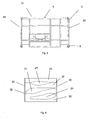
Figure 6 shows the final arrangement of the blades inside the container. -
Figures 7 and 8 shows the complete container once the assembly of the different elements is complete. - As shown in
figure 1 , the walls are formed by trusses (1) of a square tubular structure, structured in such a way that each of the side walls is formed by different trusses (1) joined together to form a side wall module. - The trusses (1) of a same wall are coupled together at the bottom using a bolt (2) with lock pin and at the top using a screw (3) which allows camber to be given to the structure, as the two coupled trusses (1) rotate in the bolt (2) fixed at the bottom and can be separated at the top allowing the thickness of the separators to be changed (4). The walls of both sides are joined together by the upper part using adjustable stays (5) with a screw ratchet (6) as shown in
figure 2 , in such a way that said adjustable stays (5) may be removed for loading and unloading the container. - As shown in
figure 3 , on the lower part of the container the tables (7) are installed, which act as support in transport or storage and which have stubs (8) that fit into the holes arranged on the side walls. Three types of tables have been designed, a rear table (7c) which serves as support for the extendable platform, another front table (7a) for coupling directly to the truck which has the King-pin assembled on it and finally, a central table (7b) which serves as a support to the container on the central supporting feet (11). All of the tables (7) incorporate retractable support feet (11) which are also telescopic with seven locking points in order to adapt to the different terrain heights in the areas where the container is loaded - unloaded. The retractable support feet (11) have been designed so that they act as a guide for assembling the side walls and are fixed by two stubs which fit into holes on the corresponding walls and are locked using a bolt (14) and lock pin, this facilitates the positioning of the walls as well as their alignment and the spacing between them. - The support feet (11) of the table (7) are telescopic and have seven locking positions which are locked with a bolt and lock pin or an interlocking bolt (14). The support feet (11) are positioned in the horizontal or retracted position with a bolt and lock pin (14) and they are positioned in the vertical position with a stay (12) which is fixed to the support foot (11) by a rotating stub and to the table (7) with the same bolt (14) which locks the support foot (11) in the horizontal foot (11) position but by changing the bolt (14) hole.
- As shown in
figures 4 and5 two types of cover have been designed, one rear cover (12) which has anchor points for two blades,figure 4 , and another front cover which has an anchor point for one blade (13),figure 5 , so that the tractor units has the greatest traction possible provided that load limits for said unit are not exceeded. Both covers (12) and (13) are coupled to the walls of the container (20) with the same type of fixture, bolt (2) and screw (3) that the trusses have (1). - Once the blades (21) are in place inside the container, each blade root is fixed to the covers (12) and (13) with two screws and two plates. Said blades (21) are inserted into metal cavities (22) located in the centre of the container (central table 7b) which avoids any damage being suffered during transport, as shown in
figure 6 . - Finally, as shown in
figures 7 and 8 , to assemble the container, the three tables (7a, 7b and 7c) are firstly aligned and situated at the correct distance. The rear truss (1) is then lifted by a central hook (not shown in the figure) and it is inserted in the pivots of the corresponding table (7). The rear truss (1) of the other side is then inserted in the same way. The rear cover (12) is then positioned, which is the cover that has anchor points for two blades (21). - The next trusses are then assembled, the trusses with the intermediate section, which are hoisted by their central hook and aligned with the rear trusses. When this process is complete, the pivots of the second (7b) and third tables (7c) are inserted. At this point the adjustment bolts (2) of the lower part of the coupling between the trusses are put in place and the screw, nuts and counternuts (3) of the upper part are adjusted. The same process is followed with the front trusses (1)
- The front cover (13), is then put in place in the same way as the rear cover (12), the front cover is that which has an anchor point for only one blade. Once the container is so assembled, the loading of the blades (21) and their respective intermediate supports (22) can take place.
- Finally, the upper adjustable stays (5) and the lower stays are put in place along with the spacers (24) which complete the container assembly process.
Claims (9)
- Container for the transport of blades comprised of side walls formed by trusses which elements have a tubular structure and squared sections, having the container support tables (7) installed in the lower part for the storages and later transport of blades, said support tables (7) incorporating support feet, and coupling both side walls using adjustable stays, characterised in that the container is formed by side walls (20), an upper and a lower part, and in that the trusses (1) of a same wall are coupled together using a bolt (2) with lock pin at the bottom and using a screw (3) at the top, with both coupled trusses (1) being able to turn in the bolt (2) fitting together at the bottom and being separated at the top therefore enabling the thickness of some separators (4), located between the trusses to be coupled, to be varied.
- Container for the transport of blades, according to claim one, characterised in that the tables (7) that serve as a support and are installed at the bottom of the container and incorporate retractable support feet (11) which are also telescopic and which serve as a guide for the assembly of the side walls.
- Container for the transport of blades, according to claim one, characterised in that the tables (7) are coupled to the container using stubs which fit into holes on the corresponding wall and which are locked with a bolt and lock pin or interlocking bolt (14).
- Container for the transport of blades, according to claim one, characterised in that the containers are closed at the front and rear by a front cover (13) which has the necessary anchor points for one blade and another rear cover (12) which has the necessary anchor points for two blades, both covers (12) and (13) being coupled to the walls of the container (20) with the same type of coupling as the trusses (1), a bolt (2) and screw (3).
- Container for the transport of blades, according to claim one, characterised in that the lower part is supported on three correctly aligned and distanced support tables (7a, 7b, 7c) with support feet (11) that are telescopic and which have seven locking positions locked with an interlocking bolt (14).
- Container for the transport of blades, according to claim five, characterised in that the support feet (11) are placed in the horizontal position, i.e. retracted, using the bolt (14) and lock pin.
- Container for the transport of blades, according to claim five, characterised in that the support feet (11) are placed in the vertical position using a stay (12) which is fixed to the support foot (11) using a rotating stub and to the table (7) with the bolt (14) which fixes the support feet (11) in the horizontal position but by changing the bolt (14) hole.
- Container for the transport of blades, according to claim one, characterised in that the walls of both sides of the container are joined together at the top using adjustable stays (5) with a screw ratchet (6) and using spacers (24) along the walls (20), in such a way that the stays (5) and the spacers (24) can be removed for loading and unloading the blades.
- Container for the transport of blades, according to claim one, characterised in that the arrangement of the blades (21) is such that their transversal axis is arranged horizontally to the container base or slightly sloped in relation to the base and in that the blades contained inside cradles (22).
Priority Applications (1)
| Application Number | Priority Date | Filing Date | Title |
|---|---|---|---|
| PL05815014T PL1829762T3 (en) | 2004-11-11 | 2005-11-10 | Transport container for blades |
Applications Claiming Priority (2)
| Application Number | Priority Date | Filing Date | Title |
|---|---|---|---|
| ES200402845A ES2253122B1 (en) | 2004-11-11 | 2004-11-11 | CONTAINER FOR THE TRANSPORTATION OF BLADES. |
| PCT/ES2005/070155 WO2006053931A1 (en) | 2004-11-11 | 2005-11-10 | Transport container for blades |
Publications (2)
| Publication Number | Publication Date |
|---|---|
| EP1829762A1 EP1829762A1 (en) | 2007-09-05 |
| EP1829762B1 true EP1829762B1 (en) | 2011-07-13 |
Family
ID=36406858
Family Applications (1)
| Application Number | Title | Priority Date | Filing Date |
|---|---|---|---|
| EP05815014A Not-in-force EP1829762B1 (en) | 2004-11-11 | 2005-11-10 | Transport container for blades |
Country Status (7)
| Country | Link |
|---|---|
| US (1) | US20070199847A1 (en) |
| EP (1) | EP1829762B1 (en) |
| CN (1) | CN100450844C (en) |
| AT (1) | ATE516194T1 (en) |
| ES (2) | ES2253122B1 (en) |
| PL (1) | PL1829762T3 (en) |
| WO (1) | WO2006053931A1 (en) |
Cited By (17)
| Publication number | Priority date | Publication date | Assignee | Title |
|---|---|---|---|---|
| US8120198B2 (en) | 2008-07-23 | 2012-02-21 | Wilic S.Ar.L. | Wind power turbine |
| US8274170B2 (en) | 2009-04-09 | 2012-09-25 | Willic S.A.R.L. | Wind power turbine including a cable bundle guide device |
| US8272822B2 (en) | 2009-01-30 | 2012-09-25 | Wilic S.Ar.L. | Wind power turbine blade packing and packing method |
| US8310122B2 (en) | 2005-11-29 | 2012-11-13 | Wilic S.A.R.L. | Core plate stack assembly for permanent magnet rotor or rotating machines |
| US8319362B2 (en) | 2008-11-12 | 2012-11-27 | Wilic S.Ar.L. | Wind power turbine with a cooling system |
| US8358189B2 (en) | 2009-08-07 | 2013-01-22 | Willic S.Ar.L. | Method and apparatus for activating an electric machine, and electric machine |
| US8410623B2 (en) | 2009-06-10 | 2013-04-02 | Wilic S. AR. L. | Wind power electricity generating system and relative control method |
| US8492919B2 (en) | 2008-06-19 | 2013-07-23 | Wilic S.Ar.L. | Wind power generator equipped with a cooling system |
| US8541902B2 (en) | 2010-02-04 | 2013-09-24 | Wilic S.Ar.L. | Wind power turbine electric generator cooling system and method and wind power turbine comprising such a cooling system |
| US8618689B2 (en) | 2009-11-23 | 2013-12-31 | Wilic S.Ar.L. | Wind power turbine for generating electric energy |
| US8659867B2 (en) | 2009-04-29 | 2014-02-25 | Wilic S.A.R.L. | Wind power system for generating electric energy |
| US8669685B2 (en) | 2008-11-13 | 2014-03-11 | Wilic S.Ar.L. | Wind power turbine for producing electric energy |
| US8937397B2 (en) | 2010-03-30 | 2015-01-20 | Wilic S.A.R.L. | Wind power turbine and method of removing a bearing from a wind power turbine |
| US8937398B2 (en) | 2011-03-10 | 2015-01-20 | Wilic S.Ar.L. | Wind turbine rotary electric machine |
| US8957555B2 (en) | 2011-03-10 | 2015-02-17 | Wilic S.Ar.L. | Wind turbine rotary electric machine |
| US8975770B2 (en) | 2010-04-22 | 2015-03-10 | Wilic S.Ar.L. | Wind power turbine electric generator and wind power turbine equipped with an electric generator |
| US9006918B2 (en) | 2011-03-10 | 2015-04-14 | Wilic S.A.R.L. | Wind turbine |
Families Citing this family (11)
| Publication number | Priority date | Publication date | Assignee | Title |
|---|---|---|---|---|
| BRPI0405546F1 (en) | 2004-12-10 | 2016-03-22 | Tecsis Tecnologia E Sist S Avançados Ltda | joint development of structures for handling, transporting and storing blades for wind turbine rotors |
| US7946591B2 (en) | 2005-09-21 | 2011-05-24 | Wilic S.Ar.L. | Combined labyrinth seal and screw-type gasket bearing sealing arrangement |
| ITBZ20050062A1 (en) | 2005-11-29 | 2007-05-30 | High Technology Invest Bv | PERMANENT MAGNET ROTOR FOR GENERATORS AND ELECTRIC MOTORS |
| ES2320959B1 (en) * | 2007-03-30 | 2010-03-12 | GAMESA INNOVATION & TECHNOLOGY, S.L. | SUPPORT FOR THE TRANSPORTATION OF BLADES. |
| US8733549B2 (en) * | 2007-11-13 | 2014-05-27 | General Electric Company | System for containing and/or transporting wind turbine components |
| CN101722887A (en) * | 2008-10-31 | 2010-06-09 | 维斯塔斯风力系统有限公司 | Conveying system for conveying blades of rotor |
| CN101648539A (en) * | 2008-10-31 | 2010-02-17 | 维斯塔斯风力系统有限公司 | Transport system for transporting wind turbine blades |
| WO2010070388A1 (en) | 2008-12-19 | 2010-06-24 | Koike, Bento Massahiko | Packing method and packing system for three aerogenerator blades |
| BRPI0925087A8 (en) | 2009-04-27 | 2015-10-06 | Tecsis Tecnologia E Sist S Avançados S A | interchangeable packaging device for wind turbine blades |
| JP2012528271A (en) * | 2009-05-26 | 2012-11-12 | レビアサン エナジー ウインド ロータス エルティディー. | 2-blade vertical axis wind turbine |
| JP2013513051A (en) * | 2009-12-03 | 2013-04-18 | シーメンス アクティエンゲゼルシャフト | Adaptive transport package |
Family Cites Families (13)
| Publication number | Priority date | Publication date | Assignee | Title |
|---|---|---|---|---|
| US3768686A (en) * | 1971-09-27 | 1973-10-30 | Matson Navigation Co | Container for elongated articles |
| US3939780A (en) * | 1974-10-09 | 1976-02-24 | Asg Industries, Inc. | Apparatus for shipping flat glass without packing cases |
| US4248472A (en) * | 1978-06-01 | 1981-02-03 | Ppg Industries, Inc. | Bow and spreader bar |
| US4258949A (en) * | 1979-07-09 | 1981-03-31 | Allied Systems Company | Extensible spreader frame for cargo containers |
| US4932830A (en) * | 1989-03-17 | 1990-06-12 | Woodburn Clarence A | Motor vehicle and boat trailer |
| EP0466686A4 (en) * | 1989-04-04 | 1992-12-09 | Ramp International East Coast U.S.A., Inc. | Apparatus for storing automobiles inside maritime containers |
| GB2257123A (en) * | 1991-03-19 | 1993-01-06 | Adamson Modular Systems Limite | Swop body container jacking system. |
| GB9805246D0 (en) * | 1998-03-12 | 1998-05-06 | Blackrock Engineering Limited | Improvements in or relating to freight container utilisation and to a pallet therefor |
| AUPP451898A0 (en) * | 1998-07-07 | 1998-07-30 | Technosearch Pty. Limited | Improvements in containers |
| ES2193808B1 (en) * | 2000-08-16 | 2004-11-01 | Moidecar, S.L. | REMOVABLE MODULAR CONTAINER. |
| US20030175089A1 (en) * | 2002-03-13 | 2003-09-18 | Preben Almind | Transport container for wind turbine blades |
| DE10214161C1 (en) * | 2002-03-28 | 2003-05-28 | Willibald Hergeth | Package for transporting turbine blades of different sizes has frusto-conical sections with surfaces which support blade laid diagonally across section |
| CN2565692Y (en) * | 2002-09-09 | 2003-08-13 | 山西焦煤集团有限责任公司 | Vehicle with universal chassis for transporting ultra long and narrow rail material |
-
2004
- 2004-11-11 ES ES200402845A patent/ES2253122B1/en not_active Expired - Fee Related
-
2005
- 2005-11-10 EP EP05815014A patent/EP1829762B1/en not_active Not-in-force
- 2005-11-10 AT AT05815014T patent/ATE516194T1/en not_active IP Right Cessation
- 2005-11-10 CN CNB200580038667XA patent/CN100450844C/en not_active Expired - Fee Related
- 2005-11-10 ES ES05815014T patent/ES2371875T3/en active Active
- 2005-11-10 PL PL05815014T patent/PL1829762T3/en unknown
- 2005-11-10 WO PCT/ES2005/070155 patent/WO2006053931A1/en active Application Filing
- 2005-11-10 US US11/663,708 patent/US20070199847A1/en not_active Abandoned
Cited By (19)
| Publication number | Priority date | Publication date | Assignee | Title |
|---|---|---|---|---|
| US8310122B2 (en) | 2005-11-29 | 2012-11-13 | Wilic S.A.R.L. | Core plate stack assembly for permanent magnet rotor or rotating machines |
| US9312741B2 (en) | 2008-06-19 | 2016-04-12 | Windfin B.V. | Wind power generator equipped with a cooling system |
| US8492919B2 (en) | 2008-06-19 | 2013-07-23 | Wilic S.Ar.L. | Wind power generator equipped with a cooling system |
| US8120198B2 (en) | 2008-07-23 | 2012-02-21 | Wilic S.Ar.L. | Wind power turbine |
| US8319362B2 (en) | 2008-11-12 | 2012-11-27 | Wilic S.Ar.L. | Wind power turbine with a cooling system |
| US8669685B2 (en) | 2008-11-13 | 2014-03-11 | Wilic S.Ar.L. | Wind power turbine for producing electric energy |
| US8272822B2 (en) | 2009-01-30 | 2012-09-25 | Wilic S.Ar.L. | Wind power turbine blade packing and packing method |
| US8274170B2 (en) | 2009-04-09 | 2012-09-25 | Willic S.A.R.L. | Wind power turbine including a cable bundle guide device |
| US8659867B2 (en) | 2009-04-29 | 2014-02-25 | Wilic S.A.R.L. | Wind power system for generating electric energy |
| US8410623B2 (en) | 2009-06-10 | 2013-04-02 | Wilic S. AR. L. | Wind power electricity generating system and relative control method |
| US8810347B2 (en) | 2009-08-07 | 2014-08-19 | Wilic S.Ar.L | Method and apparatus for activating an electric machine, and electric machine |
| US8358189B2 (en) | 2009-08-07 | 2013-01-22 | Willic S.Ar.L. | Method and apparatus for activating an electric machine, and electric machine |
| US8618689B2 (en) | 2009-11-23 | 2013-12-31 | Wilic S.Ar.L. | Wind power turbine for generating electric energy |
| US8541902B2 (en) | 2010-02-04 | 2013-09-24 | Wilic S.Ar.L. | Wind power turbine electric generator cooling system and method and wind power turbine comprising such a cooling system |
| US8937397B2 (en) | 2010-03-30 | 2015-01-20 | Wilic S.A.R.L. | Wind power turbine and method of removing a bearing from a wind power turbine |
| US8975770B2 (en) | 2010-04-22 | 2015-03-10 | Wilic S.Ar.L. | Wind power turbine electric generator and wind power turbine equipped with an electric generator |
| US8937398B2 (en) | 2011-03-10 | 2015-01-20 | Wilic S.Ar.L. | Wind turbine rotary electric machine |
| US8957555B2 (en) | 2011-03-10 | 2015-02-17 | Wilic S.Ar.L. | Wind turbine rotary electric machine |
| US9006918B2 (en) | 2011-03-10 | 2015-04-14 | Wilic S.A.R.L. | Wind turbine |
Also Published As
| Publication number | Publication date |
|---|---|
| ES2253122B1 (en) | 2007-08-01 |
| ATE516194T1 (en) | 2011-07-15 |
| CN100450844C (en) | 2009-01-14 |
| ES2371875T3 (en) | 2012-01-10 |
| CN101056788A (en) | 2007-10-17 |
| ES2253122A1 (en) | 2006-05-16 |
| WO2006053931A1 (en) | 2006-05-26 |
| US20070199847A1 (en) | 2007-08-30 |
| PL1829762T3 (en) | 2011-12-30 |
| EP1829762A1 (en) | 2007-09-05 |
Similar Documents
| Publication | Publication Date | Title |
|---|---|---|
| EP1829762B1 (en) | Transport container for blades | |
| EP2038549B1 (en) | A handling system for a wind turbine nacelle, methods for transport and vertical displacement of a wind turbine nacelle and a use of a handling system | |
| US4841708A (en) | Bolted aluminum shoring frame | |
| DK3028981T3 (en) | Crane as well as grid mast section for a grid mast for a crane of this type | |
| EP2418376B1 (en) | Transportation and storage system for wind turbine blades | |
| EP3144267B1 (en) | A loading platform | |
| US7753220B2 (en) | Reinforced and bolted rack truss | |
| US7748546B2 (en) | Reinforced and bolted rack truss | |
| JP2011122591A (en) | Wind turbine hub transportation device | |
| US20090279976A1 (en) | Versatile Shipping Platform | |
| WO2010147881A1 (en) | Kits, components and stackable trailers for transporting containers | |
| EP0049096B1 (en) | Bolted aluminium shoring frame | |
| EP3471265B1 (en) | Deployable solar tracker system | |
| CN201071547Y (en) | Folding type box combination house | |
| CA2682416A1 (en) | Open-deck freight container | |
| GB2355451A (en) | Flatrack with extended corner posts | |
| CN113911938A (en) | Detachable lattice component for crane boom | |
| CA1234298A (en) | Shoring and scaffolding frames of mechanically connected components | |
| CN216944000U (en) | Folding platform | |
| CN211081066U (en) | Movable combined discharging steel platform | |
| GB1565498A (en) | Portable buildings | |
| JPH0672487B2 (en) | Modular scaffolding platform and truss frame components used in it | |
| CN114408326A (en) | Folding platform | |
| CN117005662A (en) | Ultra-high tower multi-operation-surface combined construction platform and construction method thereof | |
| CN113401820A (en) | Underframe and crane |
Legal Events
| Date | Code | Title | Description |
|---|---|---|---|
| PUAI | Public reference made under article 153(3) epc to a published international application that has entered the european phase |
Free format text: ORIGINAL CODE: 0009012 |
|
| 17P | Request for examination filed |
Effective date: 20070605 |
|
| AK | Designated contracting states |
Kind code of ref document: A1 Designated state(s): AT BE BG CH CY CZ DE DK EE ES FI FR GB GR HU IE IS IT LI LT LU LV MC NL PL PT RO SE SI SK TR |
|
| DAX | Request for extension of the european patent (deleted) | ||
| GRAP | Despatch of communication of intention to grant a patent |
Free format text: ORIGINAL CODE: EPIDOSNIGR1 |
|
| RIN1 | Information on inventor provided before grant (corrected) |
Inventor name: LLORENTE GONZALEZ, JOSE IGNACIO Inventor name: VELEZ ORIA, SERGIO |
|
| GRAS | Grant fee paid |
Free format text: ORIGINAL CODE: EPIDOSNIGR3 |
|
| RIN1 | Information on inventor provided before grant (corrected) |
Inventor name: VELEZ ORIA, SERGIO Inventor name: LLORENTE GONZALEZ, JOSE IGNACIO |
|
| GRAA | (expected) grant |
Free format text: ORIGINAL CODE: 0009210 |
|
| AK | Designated contracting states |
Kind code of ref document: B1 Designated state(s): AT BE BG CH CY CZ DE DK EE ES FI FR GB GR HU IE IS IT LI LT LU LV MC NL PL PT RO SE SI SK TR |
|
| REG | Reference to a national code |
Ref country code: GB Ref legal event code: FG4D |
|
| REG | Reference to a national code |
Ref country code: CH Ref legal event code: EP |
|
| REG | Reference to a national code |
Ref country code: IE Ref legal event code: FG4D |
|
| REG | Reference to a national code |
Ref country code: DE Ref legal event code: R096 Ref document number: 602005029017 Country of ref document: DE Effective date: 20110901 |
|
| REG | Reference to a national code |
Ref country code: RO Ref legal event code: EPE |
|
| REG | Reference to a national code |
Ref country code: NL Ref legal event code: VDEP Effective date: 20110713 |
|
| REG | Reference to a national code |
Ref country code: PL Ref legal event code: T3 |
|
| REG | Reference to a national code |
Ref country code: ES Ref legal event code: FG2A Ref document number: 2371875 Country of ref document: ES Kind code of ref document: T3 Effective date: 20120110 |
|
| REG | Reference to a national code |
Ref country code: AT Ref legal event code: MK05 Ref document number: 516194 Country of ref document: AT Kind code of ref document: T Effective date: 20110713 |
|
| PG25 | Lapsed in a contracting state [announced via postgrant information from national office to epo] |
Ref country code: SE Free format text: LAPSE BECAUSE OF FAILURE TO SUBMIT A TRANSLATION OF THE DESCRIPTION OR TO PAY THE FEE WITHIN THE PRESCRIBED TIME-LIMIT Effective date: 20110713 Ref country code: BE Free format text: LAPSE BECAUSE OF FAILURE TO SUBMIT A TRANSLATION OF THE DESCRIPTION OR TO PAY THE FEE WITHIN THE PRESCRIBED TIME-LIMIT Effective date: 20110713 Ref country code: FI Free format text: LAPSE BECAUSE OF FAILURE TO SUBMIT A TRANSLATION OF THE DESCRIPTION OR TO PAY THE FEE WITHIN THE PRESCRIBED TIME-LIMIT Effective date: 20110713 Ref country code: PT Free format text: LAPSE BECAUSE OF FAILURE TO SUBMIT A TRANSLATION OF THE DESCRIPTION OR TO PAY THE FEE WITHIN THE PRESCRIBED TIME-LIMIT Effective date: 20111114 Ref country code: IS Free format text: LAPSE BECAUSE OF FAILURE TO SUBMIT A TRANSLATION OF THE DESCRIPTION OR TO PAY THE FEE WITHIN THE PRESCRIBED TIME-LIMIT Effective date: 20111113 Ref country code: LT Free format text: LAPSE BECAUSE OF FAILURE TO SUBMIT A TRANSLATION OF THE DESCRIPTION OR TO PAY THE FEE WITHIN THE PRESCRIBED TIME-LIMIT Effective date: 20110713 Ref country code: NL Free format text: LAPSE BECAUSE OF FAILURE TO SUBMIT A TRANSLATION OF THE DESCRIPTION OR TO PAY THE FEE WITHIN THE PRESCRIBED TIME-LIMIT Effective date: 20110713 |
|
| PG25 | Lapsed in a contracting state [announced via postgrant information from national office to epo] |
Ref country code: CY Free format text: LAPSE BECAUSE OF FAILURE TO SUBMIT A TRANSLATION OF THE DESCRIPTION OR TO PAY THE FEE WITHIN THE PRESCRIBED TIME-LIMIT Effective date: 20110713 Ref country code: SI Free format text: LAPSE BECAUSE OF FAILURE TO SUBMIT A TRANSLATION OF THE DESCRIPTION OR TO PAY THE FEE WITHIN THE PRESCRIBED TIME-LIMIT Effective date: 20110713 Ref country code: AT Free format text: LAPSE BECAUSE OF FAILURE TO SUBMIT A TRANSLATION OF THE DESCRIPTION OR TO PAY THE FEE WITHIN THE PRESCRIBED TIME-LIMIT Effective date: 20110713 Ref country code: GR Free format text: LAPSE BECAUSE OF FAILURE TO SUBMIT A TRANSLATION OF THE DESCRIPTION OR TO PAY THE FEE WITHIN THE PRESCRIBED TIME-LIMIT Effective date: 20111014 Ref country code: LV Free format text: LAPSE BECAUSE OF FAILURE TO SUBMIT A TRANSLATION OF THE DESCRIPTION OR TO PAY THE FEE WITHIN THE PRESCRIBED TIME-LIMIT Effective date: 20110713 |
|
| PG25 | Lapsed in a contracting state [announced via postgrant information from national office to epo] |
Ref country code: SK Free format text: LAPSE BECAUSE OF FAILURE TO SUBMIT A TRANSLATION OF THE DESCRIPTION OR TO PAY THE FEE WITHIN THE PRESCRIBED TIME-LIMIT Effective date: 20110713 Ref country code: CZ Free format text: LAPSE BECAUSE OF FAILURE TO SUBMIT A TRANSLATION OF THE DESCRIPTION OR TO PAY THE FEE WITHIN THE PRESCRIBED TIME-LIMIT Effective date: 20110713 |
|
| PLBE | No opposition filed within time limit |
Free format text: ORIGINAL CODE: 0009261 |
|
| STAA | Information on the status of an ep patent application or granted ep patent |
Free format text: STATUS: NO OPPOSITION FILED WITHIN TIME LIMIT |
|
| PG25 | Lapsed in a contracting state [announced via postgrant information from national office to epo] |
Ref country code: EE Free format text: LAPSE BECAUSE OF FAILURE TO SUBMIT A TRANSLATION OF THE DESCRIPTION OR TO PAY THE FEE WITHIN THE PRESCRIBED TIME-LIMIT Effective date: 20110713 |
|
| 26N | No opposition filed |
Effective date: 20120416 |
|
| PG25 | Lapsed in a contracting state [announced via postgrant information from national office to epo] |
Ref country code: MC Free format text: LAPSE BECAUSE OF NON-PAYMENT OF DUE FEES Effective date: 20111130 Ref country code: DK Free format text: LAPSE BECAUSE OF FAILURE TO SUBMIT A TRANSLATION OF THE DESCRIPTION OR TO PAY THE FEE WITHIN THE PRESCRIBED TIME-LIMIT Effective date: 20110713 |
|
| REG | Reference to a national code |
Ref country code: CH Ref legal event code: PL |
|
| PG25 | Lapsed in a contracting state [announced via postgrant information from national office to epo] |
Ref country code: CH Free format text: LAPSE BECAUSE OF NON-PAYMENT OF DUE FEES Effective date: 20111130 Ref country code: LI Free format text: LAPSE BECAUSE OF NON-PAYMENT OF DUE FEES Effective date: 20111130 |
|
| REG | Reference to a national code |
Ref country code: DE Ref legal event code: R097 Ref document number: 602005029017 Country of ref document: DE Effective date: 20120416 |
|
| REG | Reference to a national code |
Ref country code: IE Ref legal event code: MM4A |
|
| REG | Reference to a national code |
Ref country code: DE Ref legal event code: R119 Ref document number: 602005029017 Country of ref document: DE Effective date: 20120601 |
|
| PG25 | Lapsed in a contracting state [announced via postgrant information from national office to epo] |
Ref country code: IE Free format text: LAPSE BECAUSE OF NON-PAYMENT OF DUE FEES Effective date: 20111110 |
|
| PG25 | Lapsed in a contracting state [announced via postgrant information from national office to epo] |
Ref country code: LU Free format text: LAPSE BECAUSE OF NON-PAYMENT OF DUE FEES Effective date: 20111110 |
|
| PG25 | Lapsed in a contracting state [announced via postgrant information from national office to epo] |
Ref country code: DE Free format text: LAPSE BECAUSE OF NON-PAYMENT OF DUE FEES Effective date: 20120601 Ref country code: BG Free format text: LAPSE BECAUSE OF FAILURE TO SUBMIT A TRANSLATION OF THE DESCRIPTION OR TO PAY THE FEE WITHIN THE PRESCRIBED TIME-LIMIT Effective date: 20111013 |
|
| PG25 | Lapsed in a contracting state [announced via postgrant information from national office to epo] |
Ref country code: TR Free format text: LAPSE BECAUSE OF FAILURE TO SUBMIT A TRANSLATION OF THE DESCRIPTION OR TO PAY THE FEE WITHIN THE PRESCRIBED TIME-LIMIT Effective date: 20110713 |
|
| PG25 | Lapsed in a contracting state [announced via postgrant information from national office to epo] |
Ref country code: HU Free format text: LAPSE BECAUSE OF FAILURE TO SUBMIT A TRANSLATION OF THE DESCRIPTION OR TO PAY THE FEE WITHIN THE PRESCRIBED TIME-LIMIT Effective date: 20110713 |
|
| REG | Reference to a national code |
Ref country code: FR Ref legal event code: PLFP Year of fee payment: 11 |
|
| REG | Reference to a national code |
Ref country code: FR Ref legal event code: PLFP Year of fee payment: 12 |
|
| REG | Reference to a national code |
Ref country code: FR Ref legal event code: PLFP Year of fee payment: 13 |
|
| PGFP | Annual fee paid to national office [announced via postgrant information from national office to epo] |
Ref country code: PL Payment date: 20181022 Year of fee payment: 14 Ref country code: RO Payment date: 20181030 Year of fee payment: 14 |
|
| PGFP | Annual fee paid to national office [announced via postgrant information from national office to epo] |
Ref country code: GB Payment date: 20191104 Year of fee payment: 15 |
|
| PG25 | Lapsed in a contracting state [announced via postgrant information from national office to epo] |
Ref country code: RO Free format text: LAPSE BECAUSE OF NON-PAYMENT OF DUE FEES Effective date: 20191110 |
|
| PG25 | Lapsed in a contracting state [announced via postgrant information from national office to epo] |
Ref country code: IT Free format text: LAPSE BECAUSE OF NON-PAYMENT OF DUE FEES Effective date: 20191110 |
|
| GBPC | Gb: european patent ceased through non-payment of renewal fee |
Effective date: 20201110 |
|
| PG25 | Lapsed in a contracting state [announced via postgrant information from national office to epo] |
Ref country code: PL Free format text: LAPSE BECAUSE OF NON-PAYMENT OF DUE FEES Effective date: 20191110 Ref country code: GB Free format text: LAPSE BECAUSE OF NON-PAYMENT OF DUE FEES Effective date: 20201110 |
|
| PGFP | Annual fee paid to national office [announced via postgrant information from national office to epo] |
Ref country code: FR Payment date: 20211119 Year of fee payment: 17 Ref country code: ES Payment date: 20211216 Year of fee payment: 17 |
|
| PG25 | Lapsed in a contracting state [announced via postgrant information from national office to epo] |
Ref country code: FR Free format text: LAPSE BECAUSE OF NON-PAYMENT OF DUE FEES Effective date: 20221130 |
|
| REG | Reference to a national code |
Ref country code: ES Ref legal event code: FD2A Effective date: 20231228 |
|
| PG25 | Lapsed in a contracting state [announced via postgrant information from national office to epo] |
Ref country code: ES Free format text: LAPSE BECAUSE OF NON-PAYMENT OF DUE FEES Effective date: 20221111 |
|
| PG25 | Lapsed in a contracting state [announced via postgrant information from national office to epo] |
Ref country code: ES Free format text: LAPSE BECAUSE OF NON-PAYMENT OF DUE FEES Effective date: 20221111 |