EP1820449A1 - Medical x-ray detection system with active optical signalling device - Google Patents
Medical x-ray detection system with active optical signalling device Download PDFInfo
- Publication number
- EP1820449A1 EP1820449A1 EP07001742A EP07001742A EP1820449A1 EP 1820449 A1 EP1820449 A1 EP 1820449A1 EP 07001742 A EP07001742 A EP 07001742A EP 07001742 A EP07001742 A EP 07001742A EP 1820449 A1 EP1820449 A1 EP 1820449A1
- Authority
- EP
- European Patent Office
- Prior art keywords
- medical
- ray
- signal
- detection system
- ray detection
- Prior art date
- Legal status (The legal status is an assumption and is not a legal conclusion. Google has not performed a legal analysis and makes no representation as to the accuracy of the status listed.)
- Granted
Links
Images
Classifications
-
- A—HUMAN NECESSITIES
- A61—MEDICAL OR VETERINARY SCIENCE; HYGIENE
- A61B—DIAGNOSIS; SURGERY; IDENTIFICATION
- A61B6/00—Apparatus for radiation diagnosis, e.g. combined with radiation therapy equipment
-
- A—HUMAN NECESSITIES
- A61—MEDICAL OR VETERINARY SCIENCE; HYGIENE
- A61B—DIAGNOSIS; SURGERY; IDENTIFICATION
- A61B34/00—Computer-aided surgery; Manipulators or robots specially adapted for use in surgery
- A61B34/20—Surgical navigation systems; Devices for tracking or guiding surgical instruments, e.g. for frameless stereotaxis
-
- A—HUMAN NECESSITIES
- A61—MEDICAL OR VETERINARY SCIENCE; HYGIENE
- A61B—DIAGNOSIS; SURGERY; IDENTIFICATION
- A61B6/00—Apparatus for radiation diagnosis, e.g. combined with radiation therapy equipment
- A61B6/12—Devices for detecting or locating foreign bodies
-
- A—HUMAN NECESSITIES
- A61—MEDICAL OR VETERINARY SCIENCE; HYGIENE
- A61B—DIAGNOSIS; SURGERY; IDENTIFICATION
- A61B6/00—Apparatus for radiation diagnosis, e.g. combined with radiation therapy equipment
- A61B6/54—Control of apparatus or devices for radiation diagnosis
- A61B6/547—Control of apparatus or devices for radiation diagnosis involving tracking of position of the device or parts of the device
-
- A—HUMAN NECESSITIES
- A61—MEDICAL OR VETERINARY SCIENCE; HYGIENE
- A61B—DIAGNOSIS; SURGERY; IDENTIFICATION
- A61B34/00—Computer-aided surgery; Manipulators or robots specially adapted for use in surgery
- A61B34/20—Surgical navigation systems; Devices for tracking or guiding surgical instruments, e.g. for frameless stereotaxis
- A61B2034/2046—Tracking techniques
- A61B2034/2055—Optical tracking systems
-
- A—HUMAN NECESSITIES
- A61—MEDICAL OR VETERINARY SCIENCE; HYGIENE
- A61B—DIAGNOSIS; SURGERY; IDENTIFICATION
- A61B90/00—Instruments, implements or accessories specially adapted for surgery or diagnosis and not covered by any of the groups A61B1/00 - A61B50/00, e.g. for luxation treatment or for protecting wound edges
- A61B90/36—Image-producing devices or illumination devices not otherwise provided for
- A61B90/37—Surgical systems with images on a monitor during operation
- A61B2090/376—Surgical systems with images on a monitor during operation using X-rays, e.g. fluoroscopy
-
- A—HUMAN NECESSITIES
- A61—MEDICAL OR VETERINARY SCIENCE; HYGIENE
- A61B—DIAGNOSIS; SURGERY; IDENTIFICATION
- A61B6/00—Apparatus for radiation diagnosis, e.g. combined with radiation therapy equipment
- A61B6/44—Constructional features of apparatus for radiation diagnosis
- A61B6/4429—Constructional features of apparatus for radiation diagnosis related to the mounting of source units and detector units
- A61B6/4435—Constructional features of apparatus for radiation diagnosis related to the mounting of source units and detector units the source unit and the detector unit being coupled by a rigid structure
- A61B6/4441—Constructional features of apparatus for radiation diagnosis related to the mounting of source units and detector units the source unit and the detector unit being coupled by a rigid structure the rigid structure being a C-arm or U-arm
Definitions
- the invention relates to a medical X-ray detection device with an X-ray detector, which detects the presence of X-ray radiation in the medical environment, and a signal generator, which emits a signal regarding the presence of the X-ray radiation.
- X-ray detection devices are used in many cases to determine exactly when (and thus in which position of the patient) the image has been created during the registration of X-ray images in the context of medical navigation in order to allow a correct assignment of the image in the context of navigation ,
- a further processing unit novigation system
- such cables must be routed separately in the X-ray device or the registration device and they require additional interfaces to the signal-receiving components, which makes this technique relatively expensive.
- the presence of X-ray irradiation should be able to be reliably detected, wherein the detection signal can be passed on in a simple and compatible manner.
- the signal transmitter comprises an active, light-emitting signal means.
- the signal generator emits an optical signal and thereby stands out from a relatively complex cable transmission. Active light emissions can be detected directly and without loss of time, so that the presence of the X-ray irradiation can be detected very reliably over time.
- the signaling means may comprise a light-emitting diode, in particular it may also be in infrared radiators or an infrared light-emitting diode.
- the use of the wave range of the infrared light is distinguished by the advantage that interferences by light flashes in the visible light range have no influence on the signal detection.
- the invention can certainly also function with signal means which radiate in the visible light range. For example, it is conceivable to unambiguously identify the signal by comprising a specific signal sequence. If, in the context of the present description, the term "radiation of light" is used, this term thus includes visible and / or invisible components of the electromagnetic spectrum in the light region.
- the energy for the signal means can be provided in different ways, and in particular the invention comprises its own energy supply associated with the signal means, in particular a battery or an accumulator. It is also conceivable to have the energy for the signal means generated by the X-ray detector itself (from the X-ray energy) and passed on directly to the signal means. Here, a corresponding converter would be used.
- the X-ray detector can detect the beginning and / or the end of the X-ray irradiation, the signal generator emitting corresponding signals.
- this relates to a medical X-ray detection system having an X-ray detection device such as has been explained above in various embodiments, and a fluoroscopic image registration unit, wherein X-ray detector and signal generator are arranged on the fluoroscopic image registration unit.
- X-ray detector and signal generator are arranged on the fluoroscopic image registration unit.
- the signal generator is advantageously arranged on the outside of the fluoroscopic image registration unit, because it emits its signal there from the outside in a clearly visible location.
- the fluoroscopic image registration unit carries, for example, three signal transmitters and also three x-ray detectors, which can be associated with one another in every possible way. In principle, such cases are also conceivable where a single X-ray detector activates a plurality of signal transmitters or a signal generator is actuated by a plurality of X-ray detectors.
- the invention also comprises retrofittable or adaptable X-ray detection devices, and it is possible to provide the signal generator and / or X-ray detector (EN) additionally attachable and detachable to the fluoroscopic image registration unit.
- EN X-ray detector
- a medical X-ray detection system comprising an X-ray detection device as described above, and additionally an optical medical tracking system, in particular an infrared tracking system, wherein the signal transmitter in the detection range of Tracking system is arranged.
- the invention particularly shows its advantages, since an optical signal generator can be easily and directly classified in such a tracking system environment. Because such optical tracking systems exist or are used in many navigation environments, the detection signal can be easily captured, processed and incorporated into the process. Of course, such a system (with tracking system) may also have the features described above for the medical X-ray detection system.
- X-rays which are generated during the treatment or in the treatment preparation are therefore detected by a small detector unit.
- the information about the beginning and the end of the irradiation time is passed on by an active component, which can be embedded in particular within an array of passive markers.
- the integration of passive and active light transmission leads here to complement each other; Both signals are wirelessly transferable and detectable. While passive markers on such a kit are sufficient for locating a registration kit, the active signal transmission for X-ray detection optimally supplements this information transmission. It is thus possible to incorporate triggering signals for the beginning or end of the irradiation, for example, in a known navigation environment based on reflection marker technology.
- the integration of one or more X-ray detectors in the fluoroscopic image registration kit and the supplement of the marker assembly of the kit by the signal generator according to the invention thus allows an improved acquisition of newly acquired images, which brings a high reliability.
- the control according to the invention or control over this critical part of the fluoroscopic image acquisition will benefit all X-ray tracking or navigation systems from greatly reduced tracking errors. This applies in particular to C-arm X-ray systems with analog image transmission (video), because the approach according to the invention does not have the disadvantages of purely software-based image comparison methods.
- the present invention is particularly valuable because it optimally exploits existing systems that include passive marker assemblies and infrared cameras.
- An additional active infrared component would automatically by the camera system detects, of course, the wavelength of the infrared light must be within the detection range of the camera system, and thus their position would be available for further evaluation.
- Such incorporation can be easily implemented by a few changes in the software responsible for capturing other site-handling devices and the application itself could implement appropriate algorithms. No changes need to be made to the existing hardware.
- the present invention provides advantages with automatic signal detection.
- the information can be supplemented by the image comparison by the trigger signal of the signal generator during the detection of the X-ray irradiation.
- the exact time to store the tracking information would then be determined from those in the coincidence criterion, according to which both processes must take place at the same time, within a very small time interval.
- Such a more reliable way of obtaining correct tracking information will also increase patient safety.
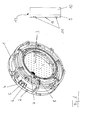
- the registration kit 1 shown in the figure is a circular attachment for the image intensifier of a C-arm X-ray apparatus (fluoroscope).
- the kit 1 comprises in the beam passage an insert with tungsten spheres 3 for the internal registration of the projection properties as well as a plurality of specially provided passive reflection markers 2, which are provided for tracking the kit 1 in a tracking and navigation environment.
- the system 13 consists of the tracking system 9 and the navigation system 10, which processes the tracking information (spatial location, determination of the treatment devices and the treatment-supporting devices, in particular spatial location, determination of the registration kit 1) and also can spend.
- the tracking system 9 has two cameras 11 and an infrared radiator 12. Infrared light from the radiator 12 is reflected, for example, by the reflection markers 2 on the kit 1 and received by the cameras 11. From these received signals, the tracking system 9 then calculates the spatial position of the kit 1 and forwards it to the navigation system 10 for processing.
- a small X-ray detector 8 is mounted on the inner circumference in the beam passage.
- the attachment is made at a location in the exterior of the image enhancement plane, which is close to the registration kit 1, and it should be noted that the detector does not interfere with the attachment of the kit. This position allows the detection of X-rays because it is applied in the form of a cone, but it does not significantly disturb the image content.
- the active optical component On the opposite side of the registration kit, on the outside at the lower protruding edge, the active optical component is fixed, namely the signal generator 4 with the active, light-emitting signal means 5, which in the present case is an infrared LED.
- the LED 5 lies in a special position known in the navigation system with respect to the reference system of the arrangement of the reflection markers 2.
- an independent power supply is provided, namely a battery 6 (or accumulator), and the detector 8 is connected to the unit of signal generator 4 and battery 6 via line 7.
- the battery can supply the necessary energy for the signal generator 4 but also for the detector 8.
- the detector 8 When a new fluoroscopic image is acquired, radiation from an X-ray source in conical form is emitted to an image intensifier. Because the detector 8 is mounted at a position which is not disturbed by the attachment of the kit 1, it can detect such radiation and trigger a signal which is emitted by the signal generator 4, ie the LED 5. If the radiation falls below a certain threshold, the trigger signal is stopped. By appropriate selection of the threshold value, a reliable measurement for the start and end time of the emitted radiation can be performed, thereby avoiding false triggering resulting from background radiation.
- the optical trigger signal is emitted in the infrared wavelength range from the LED 5, and it is therefore visible to the cameras 11 used for navigation. Because the position of the LED 5 is systemically known relative to the array of passive markers 2 (navigation system), the simultaneous observation of the marker assembly and the LED ensures that no random reflection is erroneously interpreted as a triggering signal.
- the tracking data of the cameras 11 and the tracking system 9 are permanently updated and analyzed. If the marker geometry of the registration kit 1 is observed, an additional test for the presence of the signal from the LED 5 can be made simply by checking that the signal matches an additional marker in a particular arrangement to the reference frames of the LED Registration Kits 1 complies.
- the time at which the signal is first detected may be registered as the start time of the irradiation, and the time when the signal is no longer observable is registered as the end time. No further control is performed and the acquisition of a new image is signaled to the system.
- a second possibility is to correlate the triggering signal with another signal coming from the image comparison, which is done anyway in the background.
- a new image is recognized and recognized only when both the trigger signal and the positive result of the image comparison are in coincidence (with very little added tolerance).
Abstract
Description
Die Erfindung betrifft eine medizintechnische Röntgendetektionseinrichtung mit einem Röntgendetektor, der das Vorhandensein einer Röntgenbestrahlung im medizinischen Umfeld erfasst, und einem Signalgeber, der ein Signal bezüglich des Vorhandenseins der Röntgenbestrahlung abgibt. Solche Röntgendetektionseinrichtungen werden in vielen Fällen dazu eingesetzt, bei der Registrierung von Röntgenbildern im Rahmen einer medizintechnischen Navigation genau festzustellen, wann (und damit in welcher Lage des Patienten) das Bild erstellt worden ist, um eine korrekte Zuordnung des Bildes im Rahmen der Navigation zu gestatten. Natürlich ist es grundsätzlich möglich, das Detektionssignal per Kabel zum Empfänger zu übertragen, z.B. zu einer weiterverarbeitenden Einheit (Navigationssystem). Solche Kabel müssen aber separat in der Röntgeneinrichtung bzw. der Registrierungseinrichtung verlegt werden und sie benötigen zusätzliche Schnittstellen an den das Signal empfangenden Komponenten, was diese Technik relativ aufwendig gestaltet.The invention relates to a medical X-ray detection device with an X-ray detector, which detects the presence of X-ray radiation in the medical environment, and a signal generator, which emits a signal regarding the presence of the X-ray radiation. Such X-ray detection devices are used in many cases to determine exactly when (and thus in which position of the patient) the image has been created during the registration of X-ray images in the context of medical navigation in order to allow a correct assignment of the image in the context of navigation , Of course, it is basically possible to transmit the detection signal to the receiver by cable, e.g. to a further processing unit (navigation system). However, such cables must be routed separately in the X-ray device or the registration device and they require additional interfaces to the signal-receiving components, which makes this technique relatively expensive.
Ein weiterer Ansatz im Stand der Technik besteht für den Anwendungsfall mit analogen Röntgenbild-Erzeugungssystemen darin, die Bildinformationen zu aktualisieren und bei Änderungen des Bildinhaltes eine Neuregistrierung vorzunehmen. Ein solches System ist beispielsweise aus der
Es ist die Aufgabe der vorliegenden Erfindung, eine medizinische Röntgendetektionseinrichtung bereitzustellen, welche die Probleme des Standes der Technik überwindet. Insbesondere soll das Vorhandensein einer Röntgenbestrahlung zuverlässig detektiert werden können, wobei das Detektionssignal in einfacher und kompatibler Weise weitergegeben werden kann.It is the object of the present invention to provide a medical X-ray detection device which overcomes the problems of the prior art. In particular, the presence of X-ray irradiation should be able to be reliably detected, wherein the detection signal can be passed on in a simple and compatible manner.
Diese Aufgabe wird erfindungsgemäß durch eine medizintechnische Röntgendetektionseinrichtung gemäß dem Anspruch 1 gelöst. Die Unteransprüche beschreiben bevorzugte Ausführungsformen der Erfindung.This object is achieved by a medical X-ray detection device according to claim 1. The subclaims describe preferred embodiments of the invention.
Gemäß der vorliegenden Erfindung umfasst der Signalgeber ein aktives, lichtabstrahlendes Signalmittel. Mit anderen Worten gibt der Signalgeber ein optisches Signal ab und hebt sich schon dadurch von einer relativ aufwändigen Kabelübertragung ab. Aktive Lichtabstrahlungen können unmittelbar und ohne Zeitverluste detektiert werden, so dass das Vorhandensein der Röntgenbestrahlung zeitlich sehr zuverlässig erfasst werden kann.According to the present invention, the signal transmitter comprises an active, light-emitting signal means. In other words, the signal generator emits an optical signal and thereby stands out from a relatively complex cable transmission. Active light emissions can be detected directly and without loss of time, so that the presence of the X-ray irradiation can be detected very reliably over time.
Das Signalmittel kann eine Leuchtdiode aufweisen, insbesondere kann es auch in Infrarotstrahler oder eine Infrarot-Leuchtdiode sein. Die Verwendung des Wellenbereiches des infraroten Lichtes zeichnet sich durch den Vorteil aus, dass Störungen durch Lichtblitze im Bereich des sichtbaren Lichtes keinen Einfluss auf die Signaldetektion haben. Es ist aber an dieser Stelle anzumerken, dass die Erfindung durchaus auch mit Signalmitteln funktionieren kann, die im Bereich des sichtbaren Lichtes abstrahlen. Es ist beispielsweise denkbar, das Signal eindeutig dadurch zu identifizieren, dass es eine bestimmte Signalabfolge umfasst. Wenn im Kontext der vorliegenden Beschreibung von der Abstrahlung von Licht gesprochen wird, umfasst dieser Begriff also sichtbare und/oder nicht sichtbare Anteile des elektromagnetischen Spektrums im Lichtbereich.The signaling means may comprise a light-emitting diode, in particular it may also be in infrared radiators or an infrared light-emitting diode. The use of the wave range of the infrared light is distinguished by the advantage that interferences by light flashes in the visible light range have no influence on the signal detection. However, it should be noted at this point that the invention can certainly also function with signal means which radiate in the visible light range. For example, it is conceivable to unambiguously identify the signal by comprising a specific signal sequence. If, in the context of the present description, the term "radiation of light" is used, this term thus includes visible and / or invisible components of the electromagnetic spectrum in the light region.
Die Energie für das Signalmittel kann in unterschiedlicher Weise bereitgestellt werden, und insbesondere umfasst die Erfindung eine eigene, dem Signalmittel zugeordnete Energieversorgung, insbesondere eine Batterie oder einen Akkumulator. Auch denkbar ist es, die Energie für das Signalmittel vom Röntgendetektor selbst (aus der Röntgenstrahlungsenergie) erzeugen zu lassen und direkt an das Signalmittel weiterzugeben. Hier wäre ein entsprechender Wandler einzusetzen.The energy for the signal means can be provided in different ways, and in particular the invention comprises its own energy supply associated with the signal means, in particular a battery or an accumulator. It is also conceivable to have the energy for the signal means generated by the X-ray detector itself (from the X-ray energy) and passed on directly to the signal means. Here, a corresponding converter would be used.
Der Röntgendetektor kann im Rahmen der Erfindung den Beginn und/oder das Ende der Röntgenbestrahlung erfassen, wobei der Signalgeber entsprechende Signale abgibt.In the context of the invention, the X-ray detector can detect the beginning and / or the end of the X-ray irradiation, the signal generator emitting corresponding signals.
Gemäß einem weiteren Aspekt der Erfindung betrifft diese ein medizintechnisches Röntgendetektionssystem mit einer Röntgendetektionseinrichtung wie sie beispielsweise oben in verschiedenen Ausführungen erläutert wurde, und mit einer Fluoroskop-Bildregistrierungseinheit, wobei Röntgendetektor und Signalgeber an der Fluoroskop-Bildregistrierungseinheit angeordnet sind. Es ist dabei gemäß einer Ausführungsform möglich, den Röntgendetektor im Strahlendurchgang der Fluoroskop-Bildregistrierungseinheit anzuordnen. Wichtig ist aber lediglich, dass der Röntgendetektor an einer Stelle angeordnet ist, wo er zuverlässig das Vorhandensein der Röntgenbestrahlung erfassen kann.According to a further aspect of the invention, this relates to a medical X-ray detection system having an X-ray detection device such as has been explained above in various embodiments, and a fluoroscopic image registration unit, wherein X-ray detector and signal generator are arranged on the fluoroscopic image registration unit. In this case, according to one embodiment, it is possible to arrange the X-ray detector in the beam passage of the fluoroscopic image registration unit. But it is important only that the X-ray detector is located at a location where it can reliably detect the presence of X-ray radiation.
Der Signalgeber ist vorteilhafter Weise außen an der Fluoroskop-Bildregistrierungseinheit angeordnet, weil er dort sein Signal an von außen gut sichtbarer Stelle abgibt.The signal generator is advantageously arranged on the outside of the fluoroscopic image registration unit, because it emits its signal there from the outside in a clearly visible location.
Es ist im Rahmen der Erfindung ebenfalls möglich, mehrere Signalgeber an der Fluoroskop-Bildregistrierungseinheit anzuordnen, ebenso können mehrere Röntgendetektoren dort angeordnet sein. Hierdurch lassen sich eine Redundanz und auch eine Ausfallsicherheit herstellen. Bei einer Ausführungsvariante trägt die Fluoroskop-Bildregistrierungseinheit beispielsweise drei Signalgeber und auch drei Röntgendetektoren, die in jedweder möglichen Weise einander zugeordnet sein können. Grundsätzlich sind auch solche Fälle denkbar, wo ein einziger Röntgendetektor mehrere Signalgeber ansteuert oder ein Signalgeber von mehreren Röntgendetektoren angesteuert wird.It is also possible within the scope of the invention to arrange a plurality of signal transducers on the fluoroscopic image registration unit, and a plurality of X-ray detectors can likewise be arranged there. This can be a redundancy and also a reliability. In one embodiment variant, the fluoroscopic image registration unit carries, for example, three signal transmitters and also three x-ray detectors, which can be associated with one another in every possible way. In principle, such cases are also conceivable where a single X-ray detector activates a plurality of signal transmitters or a signal generator is actuated by a plurality of X-ray detectors.
Die Erfindung umfasst in einer vorteilhaften Ausführung auch nachrüstbare oder zurüstbare Röntgendetektionseinrichtungen, und dabei besteht die Möglichkeit, Signalgeber und/oder Röntgendetektor (EN) zusätzlich anbringbar und wieder abnehmbar an der Fluoroskop-Bildregistrierungseinheit vorzusehen.In an advantageous embodiment, the invention also comprises retrofittable or adaptable X-ray detection devices, and it is possible to provide the signal generator and / or X-ray detector (EN) additionally attachable and detachable to the fluoroscopic image registration unit.
Einem weiteren Aspekt der vorliegenden Erfindung gemäß wird ein medizintechnisches Röntgendetektionssystem bereitgestellt, das eine Röntgendetektionseinrichtung aufweist, wie sie oben beschrieben wurde, und zusätzlich ein optisches medizintechnisches Trackingsystem, insbesondere ein Infrarot-Trackingsystem, wobei der Signalgeber im Erfassungsbereich des Trackingsystems angeordnet ist. In diesem Umfeld zeigt die Erfindung besonders ihre Vorteile, da sich ein optischer Signalgeber problemlos und unmittelbar in eine solche Trackingsystem-Umgebung einordnen lässt. Weil in vielen Navigations-Umfeldern solche optischen Trackingsysteme vorhanden sind oder verwendet werden, lässt sich das Detektionssignal problemlos erfassen, verarbeiten und in den Ablauf eingliedern. Natürlich kann ein solches System (mit Trackingsystem) auch die Merkmale aufweisen, die oben für das medizintechnische Röntgendetektionssystem beschrieben wurden.According to a further aspect of the present invention, there is provided a medical X-ray detection system comprising an X-ray detection device as described above, and additionally an optical medical tracking system, in particular an infrared tracking system, wherein the signal transmitter in the detection range of Tracking system is arranged. In this environment, the invention particularly shows its advantages, since an optical signal generator can be easily and directly classified in such a tracking system environment. Because such optical tracking systems exist or are used in many navigation environments, the detection signal can be easily captured, processed and incorporated into the process. Of course, such a system (with tracking system) may also have the features described above for the medical X-ray detection system.
Bei einer Ausführungsform der erfindungsgemäßen Röntgendetektion, deren verfahrensmäßige Merkmale natürlich insgesamt zur vorliegenden Offenbarung gehören, werden also Röntgenstrahlen, die während der Behandlung oder bei der Behandlungsvorbereitung erzeugt werden, durch eine kleine Detektoreinheit erfasst. Die Information über den Beginn und das Ende der Bestrahlungszeit wird durch eine aktive Komponente weitergegeben, welche speziell auch innerhalb einer Anordnung passiver Marker eingebettet sein kann. Die Integration passiver und aktiver Lichtübertragung führt hier zur gegenseitigen Ergänzung; beide Signale sind kabellos übertragbar und erfassbar. Während für die Ortung eines Registrierungs-Kits durchaus passive Marker an einem solchen Kit ausreichend sind, ergänzt die aktive Signalübertragung für die Röntgendetektion diese Informationsübertragung in optimaler Weise. Es ist somit möglich, Auslösesignale für den Beginn oder das Ende der Bestrahlung beispielsweise in ein bekanntes Navigationsumfeld einzugliedern, das auf Reflektionsmarker-Technologie basiert. Die Integration eines oder mehrerer Röntgendetektoren in das Fluoroskop-Bildregistrierungskit und die Ergänzung der Markeranordnung des Kits durch den erfindungsgemäßen Signalgeber gestattet somit eine verbesserte Erfassung neu akquirierter Bilder, die eine hohe Zuverlässigkeit mit sich bringt. Durch die erfindungsgemäße Steuerung bzw. Kontrolle über diesen kritischen Teil der Fluoroskop-Bildakquirierung werden alle Röntgen-Tracking- oder Navigationssysteme von stark reduzierten Trackingfehlern profitieren. Dies gilt speziell für C-Bogen-Röntgensysteme mit analoger Bildübertragung (Video), weil der erfindungsgemäße Ansatz nicht die Nachteile rein Software basierter Bildvergleichsmethoden aufweist.In an embodiment of the X-ray detection according to the invention, whose procedural features are of course part of the present disclosure, X-rays which are generated during the treatment or in the treatment preparation are therefore detected by a small detector unit. The information about the beginning and the end of the irradiation time is passed on by an active component, which can be embedded in particular within an array of passive markers. The integration of passive and active light transmission leads here to complement each other; Both signals are wirelessly transferable and detectable. While passive markers on such a kit are sufficient for locating a registration kit, the active signal transmission for X-ray detection optimally supplements this information transmission. It is thus possible to incorporate triggering signals for the beginning or end of the irradiation, for example, in a known navigation environment based on reflection marker technology. The integration of one or more X-ray detectors in the fluoroscopic image registration kit and the supplement of the marker assembly of the kit by the signal generator according to the invention thus allows an improved acquisition of newly acquired images, which brings a high reliability. The control according to the invention or control over this critical part of the fluoroscopic image acquisition will benefit all X-ray tracking or navigation systems from greatly reduced tracking errors. This applies in particular to C-arm X-ray systems with analog image transmission (video), because the approach according to the invention does not have the disadvantages of purely software-based image comparison methods.
Im Umfeld eines Infrarot-Trackingsystems bzw. eines hieran angeschlossenen Navigationssystems ist die vorliegende Erfindung besonders wertvoll, weil sie gerade solche vorhandenen Systeme optimal ausnutzt, die passive Markeranordnungen und Infrarotkameras umfassen. Eine zusätzliche aktive Infrarotkomponente (Signalgeber) würde automatisch durch das Kamerasystem erfasst, wobei die Wellenlänge des Infrarotlichts natürlich im Erfassungsbereich des Kamerasystems liegen muss, und somit wäre ihre Position für die weitere Auswertung verfügbar. Eine solche Eingliederung kann einfach durch wenige Änderungen in der Software umgesetzt werden, die für die Erfassung anderer Behandlungseinrichtungen bzw. behandlungsuntertützender Einrichtungen mit Positionsmarkern verantwortlich ist, und die Anwendung selbst könnte entsprechende Algorithmen implementieren. An der existierenden Hardware müssen keine Änderungen durchgeführt werden.In the environment of an infrared tracking system or a navigation system connected thereto, the present invention is particularly valuable because it optimally exploits existing systems that include passive marker assemblies and infrared cameras. An additional active infrared component (signal generator) would automatically by the camera system detects, of course, the wavelength of the infrared light must be within the detection range of the camera system, and thus their position would be available for further evaluation. Such incorporation can be easily implemented by a few changes in the software responsible for capturing other site-handling devices and the application itself could implement appropriate algorithms. No changes need to be made to the existing hardware.
Speziell für C-Bogen-Fluoroskopiegeräte mit analogem Übertragungsmodus bietet die vorliegende Erfindung mit der automatischen Signaldetektion Vorteile. Es kann beispielsweise die Information durch den Bildvergleich durch das Auslösesignal des Signalgebers bei der Erfassung der Röntgenbestrahlung ergänzt werden. Der exakte Zeitpunkt zum Speichern der Trackinginformation würde dann aus den im Koinzidenz-Kriterium ermittelt, gemäß dem beide Vorgänge zur selben Zeit stattfinden müssen, und zwar innerhalb eines sehr kleinen Zeitintervalls. Eine solchermaßen zuverlässigere Möglichkeit, korrekte Trackinginformationen zu erhalten, wird auch die Sicherheit der Patienten erhöhen.Especially for C-arm fluoroscopy devices with analog transmission mode, the present invention provides advantages with automatic signal detection. For example, the information can be supplemented by the image comparison by the trigger signal of the signal generator during the detection of the X-ray irradiation. The exact time to store the tracking information would then be determined from those in the coincidence criterion, according to which both processes must take place at the same time, within a very small time interval. Such a more reliable way of obtaining correct tracking information will also increase patient safety.
Die Erfindung wird im Weiteren anhand einer Ausführungsform und unter Bezugnahme auf die beiliegende Zeichnung näher erläutert. Sie kann alle hierin aufgeführten Merkmale in jedweder Kombination umfassen. Die einzige beiliegende Figur 1 zeigt ein Fluoroskop-Registrierungskit, das eine Röntgendetektionseinrichtung gemäß der vorliegenden Erfindung umfasst.The invention will be explained in more detail below with reference to an embodiment and with reference to the accompanying drawings. It may include all of the features listed herein in any combination. The sole accompanying Figure 1 shows a fluoroscopic registration kit comprising an X-ray detection device according to the present invention.
Das in der Figur dargestellte Registrierungskit 1 ist ein kreisförmiger Aufsatz für den Bildverstärker eines C-Bogen-Röntgengerätes (Fluoroskop). Das Kit 1 umfasst im Strahlendurchgang einen Einsatz mit Wolframkugeln 3 für die interne Registrierung der Projektionseigenschaften sowie mehrere in spezieller Anordnung vorgesehene passive Reflektionsmarker 2, die für das Tracking des Kits 1 in einem Tracking- und Navigationsumfeld vorgesehen sind. Rechts in Figur 1 ist nur schematisch eine Tracking- bzw. Navigationsanordnung aufgezeigt. Das System 13 besteht aus dem Trackingsystem 9 und dem Navigationssystem 10, welches die Trackinginformationen (räumliche Ortung, Bestimmung der Behandlungsgeräte und der behandlungsunterstützenden Geräte, insbesondere räumliche Ortung, Bestimmung des Registrierungskits 1) verarbeitet und auch ausgeben kann. Das Trackingsystem 9 weist zwei Kameras 11 auf, sowie einen Infrarot-Abstrahler 12. Infrarotlicht vom Abstrahler 12 wird beispielsweise durch die Reflektionsmarker 2 am Kit 1 reflektiert und von den Kameras 11 empfangen. Aus diesen Empfangssignalen errechnet das Trackingsystem 9 dann die räumliche Lage des Kits 1 und gibt diese zur Verarbeitung an das Navigationssystem 10 weiter.The registration kit 1 shown in the figure is a circular attachment for the image intensifier of a C-arm X-ray apparatus (fluoroscope). The kit 1 comprises in the beam passage an insert with
Am Registrierungskit 1 ist am Innenumfang im Strahlendurchgang ein kleiner Röntgendetektor 8 befestigt. Die Befestigung erfolgt an einer Stelle im Außenbereich der Bildverstärkungsebene, die nahe am Registrierungskit 1 liegt, und es ist zu beachten, dass der Detektor die Befestigung des Kits nicht stört. Diese Position gestattet die Erfassung von Röntgenstrahlen, weil diese in Form eines Kegels aufgebracht wird, aber sie stört den Bildinhalt nicht wesentlich.On the registration kit 1, a
Auf der gegenüberliegenden Seite des Registrierungskits, und zwar außen am unteren überstehenden Rand ist die aktive optische Komponente fixiert, nämlich der Signalgeber 4 mit dem aktiven, lichtabstrahlenden Signalmittel 5, das im vorliegenden Fall eine Infrarot-LED ist. In der hier dargestellten, vorteilhaften Ausführungsform liegt die LED 5 in einer speziellen im Navigationssystem bekannten Position in Bezug auf das Referenzsystem der Anordnung der Reflektionsmarker 2. Zusätzlich ist eine unabhängige Energieversorgung vorgesehen, nämlich eine Batterie 6 (bzw. Akkumulator), und der Detektor 8 ist mit der Einheit aus Signalgeber 4 und Batterie 6 über die Leitung 7 verbunden. Die Batterie kann für den Signalgeber 4 aber auch für den Detektor 8 die notwendige Energie liefern.On the opposite side of the registration kit, on the outside at the lower protruding edge, the active optical component is fixed, namely the
Wenn ein neues Fluoroskopiebild akquiriert wird, wird Strahlung aus einer Röntgenquelle in konischer Form auf einen Bildverstärker emittiert. Weil der Detektor 8 an einer Position befestigt ist, die durch die Befestigung des Kits 1 nicht gestört wird, kann er eine solche Strahlung erfassen und ein Signal auslösen, welches durch den Signalgeber 4, d.h. die LED 5 emittiert wird. Wenn die Strahlung unter einen bestimmten Schwellwert fällt, wird das Auslösesignal gestoppt. Durch die geeignete Auswahl des Schwellwertes kann eine verlässliche Messung für die Start- und Endzeit der emittierten Strahlung durchgeführt werden, wodurch Fehlauslösungen vermieden werden, die von Hintergrundstrahlung herrühren.When a new fluoroscopic image is acquired, radiation from an X-ray source in conical form is emitted to an image intensifier. Because the
Das optische Auslösesignal wird im Infrarot-Wellenlängenbereich von der LED 5 emittiert, und es ist deshalb für die Kameras 11 sichtbar, die zur Navigation verwendet werden. Weil die Position der LED 5 im Verhältnis zu der Anordnung der passiven Marker 2 systembekannt ist (Navigationssystem) stellt die gleichzeitige Beobachtung der Markeranordnung und der LED sicher, dass keine zufällige Reflektion fälschlich als Auslösesignal interpretiert wird.The optical trigger signal is emitted in the infrared wavelength range from the LED 5, and it is therefore visible to the
Im Navigationssystem 10 werden die Trackingdaten der Kameras 11 bzw. des Trackingsystems 9 permanent aktualisiert und analysiert. Wenn die Markergeometrie des Registrierungskits 1 beobachtet wird, kann ein zusätzlicher Test für das Vorhandensein des Signals von der LED 5 durchgeführt werden, und zwar in einfacher Weise dadurch, dass geprüft wird, ob das Signal einem zusätzlichen Marker in einer speziellen Anordnung gegenüber den Referenzrahmen des Registrierungskits 1 entspricht.In the
Für die Entscheidung, ob ein neues Bild akquiriert worden ist, sind zwei Modi denkbar:For deciding whether a new image has been acquired, two modes are conceivable:
Einerseits kann die Zeit, zu der das Signal zuerst erfasst wird, als Startzeit der Bestrahlung registriert werden, und die Zeit, zu der das Signal nicht mehr beobachtbar ist, wird als Endzeit registriert. Es wird keine weitere Kontrolle durchgeführt und die Akquirierung eines neuen Bildes wird dem System signalisiert.On the one hand, the time at which the signal is first detected may be registered as the start time of the irradiation, and the time when the signal is no longer observable is registered as the end time. No further control is performed and the acquisition of a new image is signaled to the system.
Eine zweite Möglichkeit besteht darin, das Auslösesignal mit einem anderen Signal zu korrelieren, das aus dem Bildvergleich stammt, der ohnehin im Hintergrund durchgeführt wird. Ein neues Bild wird erkannt, und nur dann erkannt, wenn sowohl das Auslösesignal als auch das positive Resultat des Bildvergleichs in zeitlicher Übereinstimmung sind (mit nur sehr geringer zusätzlicher Toleranz).A second possibility is to correlate the triggering signal with another signal coming from the image comparison, which is done anyway in the background. A new image is recognized and recognized only when both the trigger signal and the positive result of the image comparison are in coincidence (with very little added tolerance).
Claims (11)
Priority Applications (2)
| Application Number | Priority Date | Filing Date | Title |
|---|---|---|---|
| DE502006001440T DE502006001440D1 (en) | 2006-02-21 | 2006-02-21 | Medical X-ray detection system with active optical signal generator |
| EP07001742A EP1820449B1 (en) | 2006-02-21 | 2006-02-21 | Medical x-ray detection system with active optical signalling device |
Applications Claiming Priority (2)
| Application Number | Priority Date | Filing Date | Title |
|---|---|---|---|
| EP06003498A EP1820448B1 (en) | 2006-02-21 | 2006-02-21 | Medical X-ray detection system with active optical signal indicator |
| EP07001742A EP1820449B1 (en) | 2006-02-21 | 2006-02-21 | Medical x-ray detection system with active optical signalling device |
Related Parent Applications (1)
| Application Number | Title | Priority Date | Filing Date |
|---|---|---|---|
| EP06003498A Division EP1820448B1 (en) | 2006-02-21 | 2006-02-21 | Medical X-ray detection system with active optical signal indicator |
Publications (2)
| Publication Number | Publication Date |
|---|---|
| EP1820449A1 true EP1820449A1 (en) | 2007-08-22 |
| EP1820449B1 EP1820449B1 (en) | 2008-08-27 |
Family
ID=36691422
Family Applications (2)
| Application Number | Title | Priority Date | Filing Date |
|---|---|---|---|
| EP07001742A Expired - Fee Related EP1820449B1 (en) | 2006-02-21 | 2006-02-21 | Medical x-ray detection system with active optical signalling device |
| EP06003498A Expired - Fee Related EP1820448B1 (en) | 2006-02-21 | 2006-02-21 | Medical X-ray detection system with active optical signal indicator |
Family Applications After (1)
| Application Number | Title | Priority Date | Filing Date |
|---|---|---|---|
| EP06003498A Expired - Fee Related EP1820448B1 (en) | 2006-02-21 | 2006-02-21 | Medical X-ray detection system with active optical signal indicator |
Country Status (3)
| Country | Link |
|---|---|
| US (1) | US7863566B2 (en) |
| EP (2) | EP1820449B1 (en) |
| DE (2) | DE502006001440D1 (en) |
Cited By (1)
| Publication number | Priority date | Publication date | Assignee | Title |
|---|---|---|---|---|
| CN112168357A (en) * | 2020-11-30 | 2021-01-05 | 南京佗道医疗科技有限公司 | System and method for constructing spatial positioning model of C-arm machine |
Families Citing this family (10)
| Publication number | Priority date | Publication date | Assignee | Title |
|---|---|---|---|---|
| US9545239B2 (en) * | 2008-07-28 | 2017-01-17 | Orthosoft Inc. | X-ray detection device for C-arm tracker and method |
| US9020223B2 (en) | 2010-06-16 | 2015-04-28 | A2 Surgical | Method for determining bone resection on a deformed bone surface from few parameters |
| EP2583251B1 (en) | 2010-06-16 | 2019-07-24 | A² Surgical | A method for determining articular bone deformity resection using motion patterns |
| WO2011158114A2 (en) | 2010-06-16 | 2011-12-22 | A2 Surgical | Method and system of automatic determination of geometric elements from a 3d medical image of a bone |
| EP2583244B1 (en) | 2010-06-16 | 2019-07-24 | A² Surgical | Method of determination of access areas from 3d patient images |
| WO2011158117A2 (en) | 2010-06-16 | 2011-12-22 | A2 Surgical | Method and system of automatic determination of geometric elements characterizing a bone deformation from 3d image |
| CN103076621B (en) * | 2012-12-29 | 2015-01-07 | 中国空间技术研究院 | Folding array satellite-borne X-ray detector |
| RU2567848C1 (en) | 2014-06-18 | 2015-11-10 | Тоо "Ангстрем" | X-ray source |
| EP3295887B1 (en) * | 2016-09-16 | 2019-12-25 | Globus Medical, Inc. | Robotic fluoroscopic navigation |
| CN109938848A (en) * | 2019-03-04 | 2019-06-28 | 杭州三坛医疗科技有限公司 | Positioning system and target point positioning method |
Citations (4)
| Publication number | Priority date | Publication date | Assignee | Title |
|---|---|---|---|---|
| JPH0465694A (en) * | 1990-07-05 | 1992-03-02 | Matsushita Electric Ind Co Ltd | Pocketable dosimeter provided with alarm |
| US6236712B1 (en) * | 1998-09-25 | 2001-05-22 | Fluoroscan Imaging Systems, Inc. | Miniature C-arm apparatus with multiple x-ray indicators |
| US6470207B1 (en) * | 1999-03-23 | 2002-10-22 | Surgical Navigation Technologies, Inc. | Navigational guidance via computer-assisted fluoroscopic imaging |
| US20050242289A1 (en) * | 2004-03-26 | 2005-11-03 | James Grichnik | Radiation monitoring system |
Family Cites Families (6)
| Publication number | Priority date | Publication date | Assignee | Title |
|---|---|---|---|---|
| DE2424634B2 (en) * | 1974-05-21 | 1978-06-01 | Siemens Ag, 1000 Berlin Und 8000 Muenchen | X-ray diagnostic system |
| US4012638A (en) * | 1976-03-09 | 1977-03-15 | Altschuler Bruce R | Dental X-ray alignment system |
| US4918714A (en) * | 1988-08-19 | 1990-04-17 | Varian Associates, Inc. | X-ray tube exposure monitor |
| US4935950A (en) * | 1988-11-28 | 1990-06-19 | Radiation Measurements, Inc. | Instrument for the measurement of x-ray beam characteristics |
| DE58905562D1 (en) * | 1989-10-16 | 1993-10-14 | Siemens Ag | X-ray device. |
| ATE235187T1 (en) | 2001-05-22 | 2003-04-15 | Brainlab Ag | X-RAY IMAGE REGISTRATION DEVICE WITH A MEDICAL NAVIGATION SYSTEM |
-
2006
- 2006-02-21 EP EP07001742A patent/EP1820449B1/en not_active Expired - Fee Related
- 2006-02-21 DE DE502006001440T patent/DE502006001440D1/en active Active
- 2006-02-21 DE DE502006004913T patent/DE502006004913D1/en active Active
- 2006-02-21 EP EP06003498A patent/EP1820448B1/en not_active Expired - Fee Related
-
2007
- 2007-02-21 US US11/677,230 patent/US7863566B2/en not_active Expired - Fee Related
Patent Citations (4)
| Publication number | Priority date | Publication date | Assignee | Title |
|---|---|---|---|---|
| JPH0465694A (en) * | 1990-07-05 | 1992-03-02 | Matsushita Electric Ind Co Ltd | Pocketable dosimeter provided with alarm |
| US6236712B1 (en) * | 1998-09-25 | 2001-05-22 | Fluoroscan Imaging Systems, Inc. | Miniature C-arm apparatus with multiple x-ray indicators |
| US6470207B1 (en) * | 1999-03-23 | 2002-10-22 | Surgical Navigation Technologies, Inc. | Navigational guidance via computer-assisted fluoroscopic imaging |
| US20050242289A1 (en) * | 2004-03-26 | 2005-11-03 | James Grichnik | Radiation monitoring system |
Non-Patent Citations (1)
| Title |
|---|
| PATENT ABSTRACTS OF JAPAN vol. 016, no. 264 (P - 1370) 15 June 1992 (1992-06-15) * |
Cited By (2)
| Publication number | Priority date | Publication date | Assignee | Title |
|---|---|---|---|---|
| CN112168357A (en) * | 2020-11-30 | 2021-01-05 | 南京佗道医疗科技有限公司 | System and method for constructing spatial positioning model of C-arm machine |
| CN112168357B (en) * | 2020-11-30 | 2021-02-19 | 南京佗道医疗科技有限公司 | System and method for constructing spatial positioning model of C-arm machine |
Also Published As
| Publication number | Publication date |
|---|---|
| DE502006004913D1 (en) | 2009-11-05 |
| US7863566B2 (en) | 2011-01-04 |
| EP1820448B1 (en) | 2009-09-23 |
| US20070195933A1 (en) | 2007-08-23 |
| EP1820448A1 (en) | 2007-08-22 |
| DE502006001440D1 (en) | 2008-10-09 |
| EP1820449B1 (en) | 2008-08-27 |
Similar Documents
| Publication | Publication Date | Title |
|---|---|---|
| EP1820449B1 (en) | Medical x-ray detection system with active optical signalling device | |
| EP0857461B1 (en) | Method and system for position determination during X-ray imaging | |
| DE102014210897B4 (en) | Method and device for radiator positioning | |
| DE102015206230B4 (en) | CT system and method for determining the position and range of a mobile operating element for controlling the CT system | |
| WO2011161197A1 (en) | Device and method for combined optical and nuclear image acquisition | |
| CH684291A5 (en) | Surgical microscope for computer-assisted, stereotactic microsurgery, and method for its operation. | |
| DE102010042278A1 (en) | Operation navigation system with structured light | |
| DE19746096A1 (en) | X-ray device | |
| EP1947377A1 (en) | Opto-electronic scanner | |
| DE102004060930A1 (en) | Method for securing a medical device | |
| DE102013221383B4 (en) | Device and method for tracking a mobile, in particular wireless, sensor | |
| DE102014215651A1 (en) | A medical imaging assembly, medical imaging device having a medical imaging assembly, and methods for detecting patient motion | |
| EP4150370A1 (en) | Method for calibrating and/or adjusting, and control unit for a lidar system, lidar system, and working device | |
| DE102014218119B4 (en) | Patient transport system | |
| DE102010015633B4 (en) | Method for using a marker device in an imaging radiographic system, marker device and imaging radiographic system | |
| EP2698649A1 (en) | Self-testing monitoring sensor | |
| DE102013219137A1 (en) | Method and x-ray device for relative positioning and mutual alignment of an x-ray tube to a mobile flat detector | |
| DE102015213935B4 (en) | A medical imaging device having a positioning unit and a method for determining a position on a positioning surface | |
| DE102015206511B4 (en) | Determination of a clear spatial relationship between a medical device and another object | |
| DE102013007961B4 (en) | Optical measuring system for a vehicle | |
| DE102005011123A1 (en) | Method and device for the remote maintenance of an external component of an installed medical system | |
| EP2631668A1 (en) | Optical system and test procedure for testing the functionality of an optical system | |
| DE202017001513U1 (en) | X-ray device for examining a thorax | |
| DE102005002559A1 (en) | Failure protective circuit for use in X-ray device, has output provided for issuing deactivation signal that is generated when detector identification signal and selection signal are not received at same time | |
| DE102008023330A1 (en) | Three-dimensional reconstruction image data set generating method for examination report of patient, involves reconstructing three-dimensional image data set from two-dimensional image data sets by considering position data |
Legal Events
| Date | Code | Title | Description |
|---|---|---|---|
| PUAI | Public reference made under article 153(3) epc to a published international application that has entered the european phase |
Free format text: ORIGINAL CODE: 0009012 |
|
| 17P | Request for examination filed |
Effective date: 20070126 |
|
| AC | Divisional application: reference to earlier application |
Ref document number: 1820448 Country of ref document: EP Kind code of ref document: P |
|
| AK | Designated contracting states |
Kind code of ref document: A1 Designated state(s): AT BE BG CH CY CZ DE DK EE ES FI FR GB GR HU IE IS IT LI LT LU LV MC NL PL PT RO SE SI SK TR |
|
| 17Q | First examination report despatched |
Effective date: 20071009 |
|
| GRAP | Despatch of communication of intention to grant a patent |
Free format text: ORIGINAL CODE: EPIDOSNIGR1 |
|
| GRAS | Grant fee paid |
Free format text: ORIGINAL CODE: EPIDOSNIGR3 |
|
| AKX | Designation fees paid |
Designated state(s): DE FR GB IT |
|
| GRAA | (expected) grant |
Free format text: ORIGINAL CODE: 0009210 |
|
| AC | Divisional application: reference to earlier application |
Ref document number: 1820448 Country of ref document: EP Kind code of ref document: P |
|
| AK | Designated contracting states |
Kind code of ref document: B1 Designated state(s): DE FR GB IT |
|
| REG | Reference to a national code |
Ref country code: GB Ref legal event code: FG4D Free format text: NOT ENGLISH |
|
| REF | Corresponds to: |
Ref document number: 502006001440 Country of ref document: DE Date of ref document: 20081009 Kind code of ref document: P |
|
| PLBE | No opposition filed within time limit |
Free format text: ORIGINAL CODE: 0009261 |
|
| STAA | Information on the status of an ep patent application or granted ep patent |
Free format text: STATUS: NO OPPOSITION FILED WITHIN TIME LIMIT |
|
| 26N | No opposition filed |
Effective date: 20090528 |
|
| PG25 | Lapsed in a contracting state [announced via postgrant information from national office to epo] |
Ref country code: IT Free format text: LAPSE BECAUSE OF FAILURE TO SUBMIT A TRANSLATION OF THE DESCRIPTION OR TO PAY THE FEE WITHIN THE PRESCRIBED TIME-LIMIT Effective date: 20080827 |
|
| GBPC | Gb: european patent ceased through non-payment of renewal fee |
Effective date: 20100221 |
|
| PG25 | Lapsed in a contracting state [announced via postgrant information from national office to epo] |
Ref country code: GB Free format text: LAPSE BECAUSE OF NON-PAYMENT OF DUE FEES Effective date: 20100221 |
|
| REG | Reference to a national code |
Ref country code: DE Ref legal event code: R082 Ref document number: 502006001440 Country of ref document: DE Representative=s name: SCHWABE SANDMAIR MARX, DE |
|
| REG | Reference to a national code |
Ref country code: DE Ref legal event code: R082 Ref document number: 502006001440 Country of ref document: DE Representative=s name: SCHWABE SANDMAIR MARX, DE Effective date: 20131104 Ref country code: DE Ref legal event code: R081 Ref document number: 502006001440 Country of ref document: DE Owner name: BRAINLAB AG, DE Free format text: FORMER OWNER: BRAINLAB AG, 85622 FELDKIRCHEN, DE Effective date: 20131104 Ref country code: DE Ref legal event code: R082 Ref document number: 502006001440 Country of ref document: DE Representative=s name: SCHWABE SANDMAIR MARX PATENTANWAELTE RECHTSANW, DE Effective date: 20131104 |
|
| REG | Reference to a national code |
Ref country code: FR Ref legal event code: PLFP Year of fee payment: 11 |
|
| PGFP | Annual fee paid to national office [announced via postgrant information from national office to epo] |
Ref country code: DE Payment date: 20160218 Year of fee payment: 11 |
|
| PGFP | Annual fee paid to national office [announced via postgrant information from national office to epo] |
Ref country code: FR Payment date: 20160218 Year of fee payment: 11 |
|
| REG | Reference to a national code |
Ref country code: DE Ref legal event code: R082 Ref document number: 502006001440 Country of ref document: DE Representative=s name: SCHWABE SANDMAIR MARX PATENTANWAELTE RECHTSANW, DE Ref country code: DE Ref legal event code: R081 Ref document number: 502006001440 Country of ref document: DE Owner name: BRAINLAB AG, DE Free format text: FORMER OWNER: BRAINLAB AG, 85622 FELDKIRCHEN, DE |
|
| REG | Reference to a national code |
Ref country code: FR Ref legal event code: CA Effective date: 20170706 |
|
| REG | Reference to a national code |
Ref country code: DE Ref legal event code: R119 Ref document number: 502006001440 Country of ref document: DE |
|
| REG | Reference to a national code |
Ref country code: FR Ref legal event code: ST Effective date: 20171031 |
|
| PG25 | Lapsed in a contracting state [announced via postgrant information from national office to epo] |
Ref country code: DE Free format text: LAPSE BECAUSE OF NON-PAYMENT OF DUE FEES Effective date: 20170901 Ref country code: FR Free format text: LAPSE BECAUSE OF NON-PAYMENT OF DUE FEES Effective date: 20170228 |