EP1803558A1 - Printing unit which enables to limit the risk of a damage of the cylinder in a throw-off position by wrap round of a paper web - Google Patents
Printing unit which enables to limit the risk of a damage of the cylinder in a throw-off position by wrap round of a paper web Download PDFInfo
- Publication number
- EP1803558A1 EP1803558A1 EP06291945A EP06291945A EP1803558A1 EP 1803558 A1 EP1803558 A1 EP 1803558A1 EP 06291945 A EP06291945 A EP 06291945A EP 06291945 A EP06291945 A EP 06291945A EP 1803558 A1 EP1803558 A1 EP 1803558A1
- Authority
- EP
- European Patent Office
- Prior art keywords
- printing unit
- cylinders
- blanket
- configuration
- printing
- Prior art date
- Legal status (The legal status is an assumption and is not a legal conclusion. Google has not performed a legal analysis and makes no representation as to the accuracy of the status listed.)
- Granted
Links
Images


Classifications
-
- B—PERFORMING OPERATIONS; TRANSPORTING
- B41—PRINTING; LINING MACHINES; TYPEWRITERS; STAMPS
- B41F—PRINTING MACHINES OR PRESSES
- B41F13/00—Common details of rotary presses or machines
- B41F13/08—Cylinders
- B41F13/24—Cylinder-tripping devices; Cylinder-impression adjustments
- B41F13/26—Arrangement of cylinder bearings
- B41F13/32—Bearings mounted on swinging supports
-
- B—PERFORMING OPERATIONS; TRANSPORTING
- B41—PRINTING; LINING MACHINES; TYPEWRITERS; STAMPS
- B41F—PRINTING MACHINES OR PRESSES
- B41F13/00—Common details of rotary presses or machines
- B41F13/08—Cylinders
- B41F13/24—Cylinder-tripping devices; Cylinder-impression adjustments
- B41F13/34—Cylinder lifting or adjusting devices
- B41F13/40—Cylinder lifting or adjusting devices fluid-pressure operated
-
- B—PERFORMING OPERATIONS; TRANSPORTING
- B41—PRINTING; LINING MACHINES; TYPEWRITERS; STAMPS
- B41F—PRINTING MACHINES OR PRESSES
- B41F33/00—Indicating, counting, warning, control or safety devices
- B41F33/04—Tripping devices or stop-motions
-
- B—PERFORMING OPERATIONS; TRANSPORTING
- B41—PRINTING; LINING MACHINES; TYPEWRITERS; STAMPS
- B41F—PRINTING MACHINES OR PRESSES
- B41F33/00—Indicating, counting, warning, control or safety devices
- B41F33/18—Web break detection
-
- B—PERFORMING OPERATIONS; TRANSPORTING
- B41—PRINTING; LINING MACHINES; TYPEWRITERS; STAMPS
- B41P—INDEXING SCHEME RELATING TO PRINTING, LINING MACHINES, TYPEWRITERS, AND TO STAMPS
- B41P2233/00—Arrangements for the operation of printing presses
- B41P2233/20—Safety devices preventing damage
- B41P2233/23—Safety devices preventing damage by preventing the web winding up around cylinders
Definitions
- the present invention relates to a paper strip printing unit, of the type comprising a frame and at least a first and a second printing unit, each printing unit comprising a blanket cylinder and a cylinder plate, the printing unit also comprising a mechanism for supporting and moving the cylinders by which the printing unit has at least one pressure configuration, in which the blanket cylinders are applied against each other. another and against the plate cylinders, and at least one non-pressure configuration, wherein the blanket cylinders are spaced from each other.
- the invention applies in particular to offset presses, for example for the printing of labors.
- Such a press is known for example from computer-assisted presentation, performed at the WOA conference in Nashville on May 7, 2003, about the Sunday 2000-Auto Transfer (registered trademarks) press.
- a first off-press configuration is an off-press-off configuration, in which the unit is out of service.
- Such an off-press configuration is sometimes referred to as "throw-off" in English.
- the press-in configuration allows the printing unit to print the paper web that passes between the blanket cylinders. This configuration is sometimes referred to as "throw-on" in English.
- the blanket cylinder of each printing unit is applied against the plate cylinder of the same group, but remains spaced apart from the cylinder. blanket of the other printing group.
- the non-pressurized shut-off and plate change configurations allow the paper web to pass between the blanket cylinders of the two printing units and thus pass through the printing unit which does not perform any work. 'impression.
- the paper web may at the same time continue to be printed by other printing units.
- a masked print job can be prepared, that is, while another print job is being performed.
- the paper web breaks as it passes through a printing unit placed in a non-pressurized configuration, the web may wind around the upper blanket cylinder or the lower blanket cylinder and may very rapidly cause damage to these cylinders.
- the invention aims to limit the risk of damage to the cylinders in a unit of the aforementioned type.
- the subject of the invention is a printing unit of the aforementioned type, characterized in that the support and displacement mechanism comprises at least one element which comprises a region of least resistance intended to break under a determined effort. .
- the invention also relates to a printing press, characterized in that it comprises at least one printing unit as defined above.
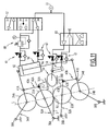
- FIG. 1 illustrates an offset rotary press 1 intended to print a strip of paper 3.
- the passage of strip 3 is horizontal, that is to say it will move horizontally, more specifically from left to right.
- the press 1 comprises mainly, and successively along the direction of travel of the paper web 3, unwinders designated by the reference numeral 5, printing units 7 to 14, a dryer / cooler 16 and at least one folder 18 .
- the printing units 7 and 8 are for example intended to print in black, the units 9 and 10 in cyan, the units 11 and 12 in magenta and the units 13 and 14 in yellow.
- the printing units 7 to 14 have similar structures and only that of the unit 8 will now be described with reference to FIG.
- the unit 8 is a dual printing unit which comprises two printing units 20A and 20B arranged one above the other.
- the upper printing unit 20A and the lower printing unit 20B have similar structures so that only that of the group 20A will be described later and the structural differences between the groups 20A and 20B will be reported.
- the numerical references used for groups 20A and 20B will be distinguished by the use of suffixes A and B.
- the printing unit 20A mainly comprises a blanket cylinder 22A, a plate cylinder 24A, an inking system, a damping system and optionally an automatic or semi-automatic plate changing system. These different systems are classic and are not represented.
- the blanket cylinder 22A is intended to receive tubular blankets, that is to say in the form of sleeves.
- Such a tubular blanket 23 is shown schematically in FIG. 9.
- the printing unit 8 also comprises a mechanism 26 for supporting and moving the cylinders 22A, 22B, 24A and 24B.
- This mechanism 26, as well as the other elements mentioned above, are carried by the frame 28 of the printing unit 8.
- the frame 28 comprises two side walls 29 between which the cylinders 22A, 22B, 24A and 24B extend. Only one wall 29 is visible in FIG.
- the support mechanism 26 comprises two sets 30, each disposed on one side of the printing unit 8 and carried by the corresponding side wall 29 of the frame 28.
- the two sets 30 have similar structures. Only that of the assembly 30 visible in Figure 2 will be described later and the differences between the two sets 30 will be reported.
- the assembly 30 comprises receiving arms of the blanket cylinders 22A and 22B, respectively designated 32A and 32B, and the receiving arms of the plate cylinders 24A and 24B, respectively designated 34A and 34B.
- the arms 32A, 32B, 34A, 34B are articulated to the wall 29 at points 36A, 36B, 38A and 38B allowing them to pivot relative to the frame 28. parallel to the axes A22A, A22B, A24A and A24B cylinders 22A, 22B, 24A and 24B.
- the hinge points 36A and 36B are located in an intermediate region of the arms 32A and 32B and the hinge points 38A and 38B are located at the left ends of the arms 34A and 34B ( Figure 2).
- the ends of the cylinders 22A, 22B, 24A and 24B located on the side of the assembly 30 are respectively rotatably received in the arms 32A, 32B, 34A and 34B by means of bearings. Each cylinder can thus rotate about its respective axis A22A, A22B, A24A and A24B.
- This rotation of the rolls takes place under the action of a drive motor which may be common to the entire printing unit 8, or for example under the action of a separate motor for each group 20A and 20B, or under the action of four separate drive motors each driving a cylinder.
- a drive motor which may be common to the entire printing unit 8, or for example under the action of a separate motor for each group 20A and 20B, or under the action of four separate drive motors each driving a cylinder.
- the bearings of the arms 32A and 32B receiving the ends of the blanket cylinders 22A and 22B are themselves received in doors 35A and 35B respectively which can pivot relative to the rest of the arms 32A and 32B about axes A1 and A2, outward, to release the bearings and the corresponding ends of the cylinders 22A and 22B.
- the doors comprise jaws 37A and 37B for gripping the bearings. At least one of the jaws 37A and 37B is movable to release the corresponding bearing.
- the jaws 37A are loosened by moving the one movable, then the door 35A is opened by pivoting about the axis A1. The door 35A then passes through an opening 39 formed in the wall 29.
- counterweight systems are for example provided on the side of the other assembly 30.
- the assembly 30 also comprises connecting rods 40A and 40B respectively connecting the arms 32A and 34A and the arms 32B and 34B. Their structure is similar and only that of the rod 40A will be described later.
- the rod 40A is articulated to the arm 34A by a hinge point 41A.
- the rod 40A is connected via a pin 42A to the right end of the arm 32A.
- the pin 42A is received in a housing 43A of the rod 40A slightly elongated along the rod 40A.
- the pin 42A can thus move in translation along the connecting rod 40A, providing a possibility of deflection which can be about 4.5 mm, although this numerical value has no limiting character.
- the pin 42A also offers a possibility of pivoting of the rod 40A relative to the arm 32A.
- the possibility of movement between the rod 40A and the arm 32A is preferably determined so that it does not occur when the gear wheels are disengaged. the relative spacing of the arms 32A and 34A.
- the pin 42A When opening the door 35A, the pin 42A follows the door 35A and out of the housing 43A. It is possible to provide means for holding the connecting rod 40A in position so that, when closing the door 35A, the pin 42A can re-engage directly in the housing 43A.
- the link 40A has, at the right of the housing 43A, a region of weakness 46A formed by local thinning ( Figure 3). This region of least resistance 46A has been dimensioned to break under a predetermined tensile force.
- the unit 8 may comprise a detector 47A breaking the connecting rod 40A.
- This is for example a printed circuit board which is arranged on the connecting rod 40A at the right of the region 46A.
- This detector 47A is connected to the unit (not shown) for controlling the press 1 to, when a breakage of the connecting rod 40A has been detected, to cause the emergency stop of the press 1 and the passage of all the units 7 to 14 in off-pressure shutdown configuration.
- the printing unit 8 comprises a system 48 for actuating the mechanism, supporting and driving 26 the cylinders.
- This system 48 comprises similar elements on each side of the unit 8, and only the elements provided on the lateral side illustrated in FIG. 2 will be described hereinafter with reference to FIG. 4.
- the system 48 comprises a main cylinder 50 for moving the arms 34A and 34B for receiving the plate cylinders 24A and 24B.
- This jack 50 is for example a pneumatic cylinder with double effect. For example, it is fed with pressurized air via a valve 52 with four orifices and two positions (FIG 4) connected to a source 53 of air under pressure.
- the jack 50 extends between the straight ends of the receiving arms 34A and 34B and is articulated thereto.
- the jack 50 has in particular a retracted configuration (FIG. 4) and an extracted configuration (FIG. 5).
- the actuating system 48 also comprises an eccentric 54 spacing the arms 32A and 32B for receiving the blanket cylinders 22A and 22B. This eccentric 54 is intended to cooperate with stops 56A and 56B, carried by the receiving arms 32A and 32B.
- the eccentric 54 is rotatable relative to the frame 28 between a spacing position and a position of approaching the arms 32A and 32B.
- the position of spacing of the arms is illustrated by Figures 2, 6 and 7.
- the eccentric 54 is then in abutment against the stops 56A and 56B.
- the eccentric 54 is not supported on the stops 56A and 56B. This position is illustrated by Figures 4 and 5.
- the eccentric 54 is movable between its aforementioned positions under the action of an auxiliary jack 58, for example double acting.
- the cylinder 58 is supplied with pressurized air via a valve with four orifices and two positions.
- the auxiliary cylinder 58 has a retracted configuration (FIGS. 4 and 5) and an extracted configuration (FIGS. 2, 6 and 7).
- Flow restrictors 61 are interposed on the pneumatic circuits between the cylinders 50 and 58 and the valves 52 and 60 to ensure smooth movements of the cylinders 22A, 22B, 24A and 24B.
- the mechanism 26 for supporting and moving the cylinders and its actuating system 48 allow the printing unit 8 to have an in-press configuration and three non-pressure configurations, namely a non-pressurized change configuration. plate, an off-press blanket change configuration and an off-press stop configuration.
- Figure 4 illustrates the in-press configuration.
- the blanket cylinders 22A and 22B and the plate cylinders 24A and 24B are then applied against each other.
- the main cylinder 50 and the auxiliary cylinder 58 are in retracted configurations and the eccentric 54 is in the position of approaching the arms 32A and 32B for receiving the blanket cylinders 22A and 22B.
- the unit 8 can then print the paper web 3 which passes between the cylinders 22A and 22B at a pinch point 62 ("nip" in English).
- the cylinders 22A, 22B, 24A and 24B are rotated about their respective central axes.
- the plate or plates carried by the plate cylinders 24A and 24B are moistened and inked by the inking and humidification systems. These plates decode the ink from their printer regions on the blankets carried by the cylinders 22A and 22B, which in turn decal the ink on the strip 3, which is thus printed on both sides.
- valve 52 was controlled to change its position.
- the main cylinder 50 is thus passed into its extracted configuration.
- the arms 34A and 34B for receiving the plate cylinders 24A and 24B were then spaced from the position they occupy in the pressure configuration.
- the receiving arm 34A was pivotally lifted about the point 38A and the receiving arm 34B was pivotally lowered about the point 38B.
- the arm 34A has driven with it, via the rod 40A, the arm 32A which has also pivoted upward around the point 36A.
- the blanket cylinder 22A has thus risen.
- the receiving arm 32B has pivoted downwardly around the point 36B, under the effect of its own weight and that of the blanket cylinder 22B, and bears on a fixed stop 63B (fig.2).
- a space 64 is then formed between the blanket cylinders 22A and 22B.
- the gap 64 has been formed by a lower uplift of the upper blanket cylinder 22A than the lowering of the blanket cylinder 22B lower.
- the displacement I1 of the upper blanket cylinder 22A, along the line L intersecting the axes of the cylinders, is in the described example of about 8.3 mm while the displacement 12 along the same line L the lower blanket cylinder 22B is about 20mm.
- the upper blanket cylinder 22A thus moved vertically by a height h1 of about 5 mm from the position it occupied in the pressure configuration.
- the lower blanket cylinder 22B has moved a height h2 of about 17mm from the position it occupied in the pressure configuration.
- widths d1 and d2 along the line L have been created between respectively the blanket cylinder 22A and plate holder 24A and the blanket cylinder 22B and plate holder 24B. These widths are respectively 3.5 and 1.8mm respectively.
- the lower blanket cylinder 22B can lift relative to the lower plate cylinder 24B, particularly in the circumstances to be described by the after.
- the configuration of Figure 5 is a configuration in which the space 64 is of a height H sufficient to allow the passage of the strip 3 printed by the printing unit 7 without it touches the blanket cylinder 22A and 22B.
- the band 3 may wrap around one of the blanket cylinders 22A and 22B. If it wraps around the upper blanket cylinder 22A, the space 66A, larger than in the other configurations described later, leaves more space for the band 3 to wind and therefore limits the risk of damage to the upper cylinders, especially the blanket cylinder 22A.
- the paper web 3 wraps around the lower blanket cylinder 22B, it will lift by pivoting the arm 32B upward as the lower space 66B is filled by the paper web. 3 winding up to a width d2 of 3.5 mm along the line L.
- the off-pressure shutdown configuration is therefore a first safety measure to limit the risk of cylinder damage in case of rupture of the strip 3.
- the connecting rod 40A or respectively 40B will break in its region 46A or 46B as soon as the predetermined force has been reached.
- the space 66A or 66B corresponding can then expand further, thereby limiting the risk of damage to the cylinders.
- the broken rods 40A or 40B can be replaced later with a much lower cost than the replacement of the blanket cylinder 22A or 22B, or another part of the mechanism 26.
- the rods 40A and 40B thus act as fuses mechanical
- Figure 6 illustrates the off-press blanket change configuration.
- valve 60 was commanded to change its position and the auxiliary cylinder 58 went into the extracted configuration.
- the eccentric 54 is thus moved to the position of spacing of the arms 32A and 32B.
- the arm 32A has thus pivoted upwardly around the point 36A, raising the upper blanket cylinder 22A.
- the distance d1 then reduced, for example by 1.7 mm, to reach 1.8 mm and the distance l1 increased by the same to reach 10 mm.
- the space 66A is then smaller than in the off-press-off configuration, but the space 64 is larger.
- a stop 63A (FIG. 2) was then actuated to bear against the end (on the left in FIG. 2) of the arm 32A, thus preventing its downward movement. Similarly, the left end of the arm 32B is always bearing against the fixed stop 63B. Note that no stop 63A or 63B is provided on the side of the unit 8 opposite to that shown in Figure 2.
- the blanket can also be changed on the printing unit 8 while other units of the press perform a print job.
- Figure 7 illustrates the non-pressure plate change configuration.
- valve 52 has been controlled to bring the cylinder 50 into an intermediate configuration between its retracted and retracted configurations.
- the lower plate cylinder 24B has thus been raised by pivoting up the arm 34B around the point 38B until it bears against the lower blanket cylinder 22B.
- the upper plate cylinder 24A has been lowered by pivoting down the arm 34A until it bears against the blanket cylinder 22A.
- the plate and blanket cylinders of each of the groups 20A and 20B are then applied against each other.
- Stops 68A and 68B (FIG 2) carried by the arms 32A, 32B, 34A and 34B are then in abutment on one another.
- the non-pressure plate change configuration makes it possible to ensure the removal and placement of the plates on the plate cylinders 24A and 24B, for example by a manual, automatic or semi-automatic process.
- the space 64 has a global height H sufficient for the web 3 to pass through the printing unit 8, for example after having been printed by the printing unit 7, without touching the blanket cylinders. 22A and 22B.
- the printing unit 8 can therefore be prepared, by installing the printing plates for a next print job, while the printing press 1 is performing another print job.
- non-pressure configurations described above thus make it possible to ensure the preparation of certain units of the press, for example 8, 10, 12 and 14, while other printing units, for example 7, 9, 11, 13 , perform another print job.
- the change from one print job to another can then be made in flight, that is to say while the paper strip 3 scrolls, even at full speed, without the need to cut the strip of paper or to re-engage.
- some printing units of the press 1 may be prepared in masked time, that is, while a print job is being performed by some other units of the press 1. This possibility is increased by compared to the state of the art, since even the blanket change of some units can be performed while the press 1 provides a print job, which was not the case in the state of the art.
- the press can save even more time, can have an even higher utilization rate and thus leads to lower costs.
- the paper strip 3 will have a downward arrow f between two printing units placed in an in-press configuration.
- FIG. 8 This is illustrated in FIG. 8 in which only the printing units 7 to 9 have been represented, the units 7 and 9 being in pressurized configuration and the printing unit 8 located downstream of the unit 7. and upstream of the unit 9, being in the non-pressure plate change configuration.
- the paper strip 3 is, because of the arrow f, located at a lower level than it would occupy if the printing unit 8 was in an in-press configuration.
- the height h2 (fig.7) being greater than the height h1, the risks of contact of the band 3 with the lower blanket cylinder 22B are reduced and it is not necessary to provide means for guiding the band 3 between unit 8 and units 7 and 9.
- the printing units have other structures, for example with lines L inclined relative to the vertical opposite to that shown, it is the height h1 which can be greater than the height h2. Indeed, the arrow f can then be oriented upwards.
- the characteristics relating to the differences in heights h2 and h1 can be used with printing units having less off-press configuration than in the example described.
- Such printing units may, for example, not have an off-press blanket change configuration.
- the blanket change operation can not then be performed while the press 1 provides another print job.
- rods 40A and 40B can be used independently of the off-pressure configurations described above and different amplitudes of displacement of the blanket cylinders. It is also possible to use such rods for only one of the printing groups.
- other elements of the support and displacement mechanism 26 may, in addition to or in place of the connecting rods 40A and 40B, have a zone of weakness to form a mechanical fuse.
- a zone of weakness to form a mechanical fuse.
- the first security measure described above to limit the risk of damage to the cylinders can also be achieved with other support mechanisms and drive 26.
- the two spaces 66A and 66B can have in this configuration widths d1 and d2 greater than those they have in other non-pressure configurations.
- the enlargement possibility described for the space 66B can also be implemented for the upper printing unit 20A. This enlargement can thus be ensured, not by a displacement of the blanket cylinder, as described above, but by a displacement of the plate cylinder or even by a displacement of these two cylinders.
- the units 7 and 11 may be intended to print in black, the units 8 and 12 in cyan, the units 9 and 13 in magenta and the units 10 and 14 in yellow.
- the press 1 may comprise a number of printing units different from that of FIG. 1, preferably greater than 2, and all the printing units do not necessarily have the structure described above.
- the height H of the space 64 in the non-pressure configurations will be greater than 10 mm in order to allow the strip 3 to pass through the printing units which do not print, without touching their blanket cylinders. .
- this value should not be considered as limiting, other lower values that can achieve this goal.
- the height H allowing passage of the paper web 3 without touching the blanket cylinders depends in particular on the diameter of the blanket cylinders, the inclination of the line L with respect to the vertical, the distance between the successive printing units and the drawing of the ink.
- These elements comprise a drawbar 70 which extends inside the frame 28 parallel to the axes of the cylinders 22A and 22B over substantially their entire length.
- the lateral ends of this bar 70 are releasably mounted each on a side chain 72.
- These side chains 72 are for example endless chains. Only one of the strands 74 of these chains 72 is shown in FIG. 10, the return strands having not been represented.
- Each strand 74 extends from one side of the press 1 through all the printing units 7 to 14.
- the press 1 also comprises a motor for driving the chains 72 so as to cause a horizontal displacement of the bar 70 of the printing unit 7 towards the printing unit 14, as shown by the arrow 78 on the figure 10.
- the ends of the bar 70 are fixed on the chains 72 at the entrance of the unit. 7.
- the front edge 80 of the paper web 3 has been previously fixed or is then fixed to the bar 70, then the bar 70 is caused to move as shown by the arrow 78.
- the bar 70 then pulls the paper strip 3 through the units 7 to 14 of the press and an operator can then recover the leading edge 80 of the strip 3 at the output of the printing unit 14.
- the tape engagement operation in the printing units 7 to 14 can therefore be performed by one person and at one time.
- the pulling of the band 3 in the printing units by virtue of the bar 70 makes it possible, in comparison with the conventional systems of band engagement where the band is only pulled from one of its sides, to keep a good centering of the band 3 in the printing units.
- the heights H important spaces 64 are particularly advantageous for such a mode of engagement of the band 3, since they allow the bar 70 to have a relatively large diameter, avoiding damaging bending.
- the bar 70 may be that used for the engagement operations of the strip 3 in the unwinders 5 and the dryer / cooler 16.
- the bar 70 is then adapted to be mounted on the drive devices and in the possible guides of the web engagement systems which are provided with these other elements of the press 1.
- the bar 70 can be moved by other types of chains than endless chains 72, or even by other drive devices. These drive devices may be provided only on one side of the press 1 and not both as shown in Figure 10.
- This type of engagement of the band can be used with a press 1 comprising only one unwinder, comprising a separate dryer and a cooler and / or not including a dryer.
- this type of engagement of the band 3 within the printing units of the press can be used independently of the characteristics described above and in particular those relating to the dimensions obtained for the height H of the spaces 64.
- FIG 11 shows a variant of the unit 8 of Figures 1 to 7, the valve 52 has been replaced by a valve with five ports and three positions. This valve 52 thus has an additional position called centering spring. In this additional position, the two outlets of the valve 52 are supplied by the air from the source 53. The two chambers 82 and 84 located on either side of the piston of the cylinder 50 are thus supplied with compressed air.
- the valve 52 first goes into spring centering position.
- the air pressures in the chambers 82 and 84 are therefore balanced and the cylinders 22B and 24B of the lower printing unit 20B descend under the effect of their own weight.
- the control unit of the press 1 causes the passage of the valve 52 in the position where the chamber 82 is supplied with pressurized air and the chamber 84 is vented.
- This pressure limiter 86 when arranged as in FIG. 11 upstream of the chamber 82, makes it possible to reduce the pressure in this chamber 82 relative to that in the chamber 84, when the valve 52 is in the centering position. spring. The pressure limiter 86 then makes it possible to slow down further the descent of the cylinders of the lower printing unit 20B during the transition to the off-press-off configuration.
Abstract
Description
La présente invention concerne une unité d'impression d'une bande de papier, du type comprenant un bâti et au moins un premier et un deuxième groupes d'impression, chaque groupe d'impression comprenant un cylindre porte-blanchet et un cylindre porte-plaque, l'unité d'impression comprenant également un mécanisme de support et de déplacement des cylindres grâce auquel l'unité d'impression présente au moins une configuration en-pression, dans laquelle les cylindres porte-blanchet sont appliqués l'un contre l'autre et contre les cylindres porte-plaque, et au moins une configuration hors-pression, dans laquelle les cylindres porte-blanchet sont espacés l'un de l'autre.The present invention relates to a paper strip printing unit, of the type comprising a frame and at least a first and a second printing unit, each printing unit comprising a blanket cylinder and a cylinder plate, the printing unit also comprising a mechanism for supporting and moving the cylinders by which the printing unit has at least one pressure configuration, in which the blanket cylinders are applied against each other. another and against the plate cylinders, and at least one non-pressure configuration, wherein the blanket cylinders are spaced from each other.
L'invention s'applique en particulier à des presses offset, par exemple pour l'impression de labeurs.The invention applies in particular to offset presses, for example for the printing of labors.
Une telle presse est connue par exemple de la présentation assistée par ordinateur, effectuée à la conférence WOA à Nashville le 7 mai 2003, au sujet de la presse Sunday 2000- Auto Transfer (marques déposées).Such a press is known for example from computer-assisted presentation, performed at the WOA conference in Nashville on May 7, 2003, about the Sunday 2000-Auto Transfer (registered trademarks) press.
Une première configuration hors-pression est une configuration hors-pression d'arrêt, dans laquelle l'unité est hors-service. Une telle configuration hors-pression est parfois désignée « throw-off » en anglais.A first off-press configuration is an off-press-off configuration, in which the unit is out of service. Such an off-press configuration is sometimes referred to as "throw-off" in English.
La configuration en-pression permet à l'unité d'impression d'imprimer la bande de papier qui passe entre les cylindres porte-blanchet. Cette configuration est parfois désignée « throw-on » en anglais.The press-in configuration allows the printing unit to print the paper web that passes between the blanket cylinders. This configuration is sometimes referred to as "throw-on" in English.
Dans une deuxième configuration hors-pression, dénommée par la suite hors-pression de changement de plaque, le cylindre porte-blanchet de chaque groupe d'impression est appliqué contre le cylindre porte-plaque du même groupe, mais reste espacé du cylindre porte-blanchet de l'autre groupe d'impression.In a second non-pressurized configuration, hereinafter referred to as plate-releasing pressure, the blanket cylinder of each printing unit is applied against the plate cylinder of the same group, but remains spaced apart from the cylinder. blanket of the other printing group.
Les configurations hors-pression d'arrêt et de changement de plaques permettent à la bande de papier de passer entre les cylindres porte-blanchet des deux groupes d'impression et ainsi de traverser l'unité d'impression qui n'effectue aucun travail d'impression. La bande de papier peut dans le même temps continuer à être imprimée par d'autres unités d'impression.The non-pressurized shut-off and plate change configurations allow the paper web to pass between the blanket cylinders of the two printing units and thus pass through the printing unit which does not perform any work. 'impression. The paper web may at the same time continue to be printed by other printing units.
Cela permet d'assurer, au sein d'une même presse d'impression, un travail d'impression grâce à certaines unités, tandis que les plaques d'autres unités sont changées pour préparer le travail d'impression suivant.This makes it possible to perform printing work within the same printing press by means of certain units, while the plates of other units are changed to prepare the next printing job.
Ainsi, on peut changer de travail d'impression sans couper la bande de papier et les pertes de papier lors du changement de travail d'impression sont limitées.Thus, you can change the print job without cutting the paper tape and paper waste when changing the print job is limited.
En outre, on peut préparer un travail d'impression en temps masqué, c'est-à-dire pendant qu'un autre travail d'impression est effectué.In addition, a masked print job can be prepared, that is, while another print job is being performed.
Ainsi, une telle presse, généralement qualifiée de presse « Auto Transfer » (marque déposée), permet de gagner du temps, a un taux d'utilisation élevé et permet donc de réduire les coûts.Thus, such a press, generally referred to as "Auto Transfer" (registered trademark), saves time, has a high utilization rate and thus reduces costs.
Si la bande de papier se rompt alors qu'elle traverse une unité d'impression placée en configuration hors-pression, la bande risque de s'enrouler autour du cylindre porte-blanchet supérieur ou du cylindre porte-blanchet inférieur et peut très rapidement de provoquer l'endommagement de ces cylindres.If the paper web breaks as it passes through a printing unit placed in a non-pressurized configuration, the web may wind around the upper blanket cylinder or the lower blanket cylinder and may very rapidly cause damage to these cylinders.
Le remplacement d'un tel cylindre étant une opération extrêmement coûteuse, l'invention a pour but de limiter les risques d'endommagement des cylindres dans une unité du type précité.The replacement of such a cylinder is an extremely expensive operation, the invention aims to limit the risk of damage to the cylinders in a unit of the aforementioned type.
A cet effet, l'invention a pour objet une unité d'impression du type précité, caractérisée en ce que le mécanisme de support et de déplacement comprend au moins un élément qui comporte une région de moindre résistance destinée à se rompre sous un effort déterminé.For this purpose, the subject of the invention is a printing unit of the aforementioned type, characterized in that the support and displacement mechanism comprises at least one element which comprises a region of least resistance intended to break under a determined effort. .
Selon des modes particuliers de réalisation de l'invention, l'unité peut comprendre l'une ou plusieurs des caractéristiques suivantes, prise(s) isolément ou selon toutes les combinaisons techniquement possibles :
- l'élément est une liaison reliant le cylindre porte-plaque et le cylindre porte-blanchet d'au moins un groupe d'impression ;
- le mécanisme de support comprend des bras de réception des cylindres, les bras de réception étant articulés sur le bâti pour pouvoir pivoter autour d'axes parallèles aux cylindres porte-plaque et porte-blanchet, les extrémités des cylindres tourillonnent dans les bras de réception, et la liaison comprend une bielle reliant les bas de réception des cylindres porte-blanchet et porte-plaque dudit groupe d'impression ;
- la bielle est articulée à l'un des bras de réception par un pion mobile en translation par rapport à la bielle ;
- la région de moindre résistance est formée par un amincissement local de la bielle ;
- ledit groupe d'impression est situé au-dessus de l'autre groupe d'impression ;
- une configuration hors-pression est une configuration hors-pression d'arrêt dans laquelle les cylindres porte-blanchet sont espacés des cylindres porte-plaque de leurs groupes d'impression respectifs ;
- une configuration hors-pression est une configuration hors-pression de changement de blanchet dans laquelle les cylindres porte-blanchet sont espacés des cylindres porte-plaque de leurs groupes d'impression respectifs ;
- dans la configuration hors-pression d'arrêt, la largeur de l'espace entre le cylindre porte-blanchet et le cylindre porte-plaque d'au moins un groupe d'impression est supérieure à la largeur du même espace lorsque l'unité est en configuration hors-pression de changement de blanchet ;
- dans la configuration hors-pression d'arrêt, le mécanisme de support et de déplacement est adapté pour permettre un déplacement du cylindre porte-blanchet et/ou du cylindre porte-plaque d'au moins un groupe d'impression de sorte que la largeur de l'espace entre le cylindre porte-blanchet et le cylindre porte-plaque dudit groupe d'impression est supérieure à la largeur du même espace lorsque la presse est en configuration hors-pression de changement de blanchet ;
- une configuration hors-pression est une configuration hors-pression de changement de plaque, dans laquelle les cylindres porte-blanchet sont appliqués contre les cylindres porte-plaque de leurs groupes d'impression respectifs ;
- dans la ou chaque configuration hors-pression, un espace suffisant est ménagé entre les cylindres porte-blanchet pour permettre le passage entre eux d'une bande de papier imprimée par une autre unité d'impression ;
- l'unité comprend un détecteur de rupture de la région de moindre résistance ; et
- le détecteur est raccordé à une unité de commande de l'unité d'impression.
- the element is a link connecting the plate cylinder and the blanket cylinder of at least one printing unit;
- the support mechanism comprises cylinders receiving arms, the receiving arms being hinged to the frame to be pivotable about axes parallel to the plate and blanket cylinder, the ends of the cylinders are journalled in the receiving arms, and the link comprises a connecting rod connecting the receiving bottom of the blanket cylinder and plate holder of said printing unit;
- the connecting rod is articulated to one of the receiving arms by a pin movable in translation relative to the connecting rod;
- the region of least resistance is formed by a local thinning of the connecting rod;
- said printing group is located above the other printing group;
- a non-pressure configuration is a non-pressurized shutdown configuration in which the blanket cylinders are spaced apart from the plate cylinders of their respective printing units;
- a non-pressurized configuration is a blanket blanket pressure configuration in which the blanket cylinders are spaced apart from the plate cylinders of their respective printing units;
- in the off-press-off configuration, the width of the space between the blanket cylinder and the plate cylinder of at least one printing unit is greater than the width of the same space when the unit is in an off-press blanket change configuration;
- in the off-press-off configuration, the support and displacement mechanism is adapted to allow movement of the blanket cylinder and / or the plate cylinder of at least one printing unit so that the width the space between the blanket cylinder and the plate cylinder of said printing unit is greater than the width of the same space when the press is in an off-press blanket changing configuration;
- a non-pressure configuration is a non-pressing plate change configuration, in which the blanket cylinders are pressed against the plate cylinders of their respective printing units;
- in the or each non-pressure configuration, sufficient space is provided between the blanket cylinders to allow passage of paper tape printed by another printing unit;
- the unit includes a break detector of the region of least resistance; and
- the detector is connected to a control unit of the printing unit.
L'invention a également pour objet une presse d'impression, caractérisée en ce qu'elle comprend au moins une unité d'impression telle que définie ci-dessus.The invention also relates to a printing press, characterized in that it comprises at least one printing unit as defined above.
L'invention sera mieux comprise à la lecture de la description qui va suivre, donnée uniquement à titre d'exemple, et faite en se référant aux dessins annexés, sur lesquels :
- la figure 1 est une vue latérale schématique d'une presse d'impression selon l'invention,
- la figure 2 est une vue latérale schématique agrandie, illustrant le mécanisme de support et d'entraînement des cylindres d'une unité d'impression de la presse de la figure 1, et la figure 2 étant prise depuis l'intérieur de l'unité,
- la figure 3 est une vue schématique agrandie de la partie cerclée III de la figure 2,
- les figures 4 à 7 sont des schémas cinématiques latéraux, illustrant différentes configurations de l'unité d'impression de la figure 2,
- la figure 8 est une vue schématique latérale illustrant trois unités d'impression successives de la presse de la figure 1,
- la figure 9 est une schématique en perspective d'un blanchet tubulaire susceptible d'être utilisé avec la presse de la figure 1,
- la figure 10 est une vue schématique en perspective de l'unité d'impression de la figure 2, illustrant un système d'engagement de la bande de papier, et
- la figure 11 est une vue analogue à la figure 4, illustrant une variante de l'unité d'impression des figures 2 à 7.
- FIG. 1 is a schematic side view of a printing press according to the invention,
- FIG. 2 is an enlarged schematic side view illustrating the mechanism for supporting and driving the rolls of a printing unit of the press of FIG. 1, and FIG. 2 being taken from inside the unit. ,
- FIG. 3 is an enlarged schematic view of the circled portion III of FIG. 2,
- FIGS. 4 to 7 are lateral kinematic diagrams, illustrating different configurations of the printing unit of FIG. 2,
- FIG. 8 is a schematic side view illustrating three successive printing units of the press of FIG. 1,
- FIG. 9 is a schematic view in perspective of a tubular blanket that can be used with the press of FIG. 1,
- FIG. 10 is a schematic perspective view of the printing unit of FIG. 2, illustrating a system for engaging the paper web, and
- FIG. 11 is a view similar to FIG. 4, illustrating a variant of the printing unit of FIGS. 2 to 7.
La figure 1 illustre une presse rotative offset 1 destinée à imprimer une bande de papier 3. Dans l'exemple représenté, le passage de la bande 3 est horizontal, c'est-à-dire qu'elle va se déplacer horizontalement, plus spécifiquement de la gauche vers la droite.FIG. 1 illustrates an offset
La presse 1 comprend principalement, et successivement le long du sens de défilement de la bande de papier 3, des dérouleurs désignés par la référence numérique 5, des unités d'impression 7 à 14, un sécheur/refroidisseur 16 et au moins une plieuse 18.The
Les unités d'impression 7 et 8 sont par exemple destinées à imprimer en noir, les unités 9 et 10 en cyan, les unités 11 et 12 en magenta et les unités 13 et 14 en jaune.The
Les unités d'impression 7 à 14 ont des structures analogues et seule celle de l'unité 8 va maintenant être décrite par référence à la figure 2.The
L'unité 8 est une unité d'impression double qui comprend deux groupes d'impression 20A et 20B disposés l'un au-dessus de l'autre.The
Le groupe d'impression supérieur 20A et le groupe d'impression inférieur 20B ont des structures analogues de sorte que seule celle du groupe 20A sera décrite par la suite et les différences de structure entre les groupes 20A et 20B seront signalées. Les références numériques utilisées pour les groupes 20A et 20B se distingueront par l'emploi des suffixes A et B.The
Le groupe d'impression 20A comprend principalement un cylindre porte-blanchet 22A, un cylindre porte-plaque 24A, un système d'encrage, un système de mouillage et éventuellement un système automatique ou semi-automatique de changement de plaques. Ces différents systèmes sont classiques et ne sont pas représentés. Dans l'exemple représenté, le cylindre porte-blanchet 22A est destiné à recevoir des blanchets tubulaires, c'est-à-dire sous forme de manchons.The
Un tel blanchet tubulaire 23 est représenté schématiquement sur la figure 9.Such a
L'unité d'impression 8 comprend également un mécanisme 26 de support et de déplacement des cylindres 22A, 22B, 24A et 24B. Ce mécanisme 26, ainsi que les autres éléments mentionnés précédemment, sont portés par le bâti 28 de l'unité d'impression 8. Le bâti 28 comprend deux parois latérales 29 entre lesquelles les cylindres 22A, 22B, 24A et 24B s'étendent. Seule une paroi 29 est visible sur la figure 2.The
Le mécanisme de support 26 comprend deux ensembles 30, chacun disposé d'un côté de l'unité d'impression 8 et porté par la paroi latérale 29 correspondante du bâti 28. Les deux ensembles 30 ont des structures analogues. Seule celle de l'ensemble 30 visible sur la figure 2 sera décrite par la suite et les différences entre les deux ensembles 30 seront signalées.The
L'ensemble 30 comprend des bras de réception des cylindres porte-blanchet 22A et 22B, respectivement désignés 32A et 32B, et des bras de réception des cylindres porte-plaque 24A et 24B, respectivement désignés 34A et 34B.The
Les bras 32A, 32B, 34A, 34B sont articulés à la paroi 29 en des points 36A, 36B, 38A et 38B leur permettant de pivoter par rapport au bâti 28 parallèlement aux axes A22A, A22B, A24A et A24B des cylindres 22A, 22B, 24A et 24B.The
Dans l'exemple représenté, les points d'articulation 36A et 36B sont situés dans une région intermédiaire des bras 32A et 32B et les points d'articulation 38A et 38B sont situés aux extrémités gauches des bras 34A et 34B (figure 2).In the example shown, the hinge points 36A and 36B are located in an intermediate region of the
Les extrémités des cylindres 22A, 22B, 24A et 24B situées du côté de l'ensemble 30 sont reçues à rotation respectivement dans les bras 32A, 32B, 34A et 34B par l'intermédiaire de paliers. Chaque cylindre peut ainsi tourner autour de son axe A22A, A22B, A24A et A24B respectif.The ends of the
Cette rotation des cylindres s'effectue sous l'action d'un moteur d'entraînement qui peut être commun à l'ensemble de l'unité d'impression 8, ou par exemple sous l'action d'un moteur séparé pour chaque groupe d'impression 20A et 20B, ou encore sous l'action de quatre moteurs d'entraînement séparés entraînant chacun un cylindre.This rotation of the rolls takes place under the action of a drive motor which may be common to the
Les paliers des bras 32A et 32B recevant les extrémités des cylindres porte-blanchet 22A et 22B sont reçus eux-mêmes dans des portes 35A et respectivement 35B qui peuvent pivoter par rapport au reste des bras 32A et 32B autour d'axes A1 et A2, vers l'extérieur, pour libérer les paliers et les extrémités correspondantes des cylindres 22A et 22B.The bearings of the
Plus précisément, les portes comprennent des mors 37A et 37B pour enserrer les paliers. Au moins un des mors 37A et 37B est mobile pour pouvoir libérer le palier correspondant.More specifically, the doors comprise
Ainsi, pour dégager par exemple l'extrémité du cylindre porte-blanchet 22A, on desserre les mors 37A en déplaçant celui qui est mobile, puis on ouvre la porte 35A par pivotement autour de l'axe A1. La porte 35A passe alors au travers d'une ouverture 39 ménagée dans la paroi 29.Thus, to release for example the end of the
Il est alors possible de changer le blanchet par translation le long du cylindre porte-blanchet 22A et passage au travers de l'ouverture 39. De telles portes 35A, 35B et de tels mors 37A, 37B ne sont prévus que dans un des ensembles 30, en l'occurrence celui représenté sur la figure 2.It is then possible to change the blanket by translation along the
Afin de pouvoir assurer le maintien horizontal des cylindres porte-blanchet 22A et 22B, alors que les paliers situés du côté de l'ensemble 30 de la figure 2 ne sont plus supportés par les portes 35A et 35B, des systèmes formant contre-poids sont par exemple prévus du côté de l'autre ensemble 30.In order to be able to maintain horizontally the
De tels systèmes de portes 35A et 35B et de mors 37A et 37B, et de tels systèmes de contre-poids sont classiques et sont par exemple décrits respectivement dans les documents
L'ensemble 30 comprend également des bielles 40A et 40B reliant respectivement les bras 32A et 34A et les bras 32B et 34B. Leur structure est analogue et seule celle de la bielle 40A sera décrite par la suite.The
La bielle 40A est articulée au bras 34A par un point d'articulation 41A. La bielle 40A est liée via un pion 42A à l'extrémité droite du bras 32A. Le pion 42A est reçu dans un logement 43A de la bielle 40A légèrement allongé le long de la bielle 40A. Le pion 42A peut ainsi se déplacer en translation le long de la bielle 40A, offrant une possibilité de débattement qui peut être d'environ 4,5 mm, bien que cette valeur numérique n'ait aucun caractère limitatif. Le pion 42A offre également une possibilité de pivotement de la bielle 40A par rapport au bras 32A.The
Lorsque les cylindres porte-plaque 24A et porte-blanchet 22A ont des roues dentées en prise, la possibilité de débattement entre la bielle 40A et le bras 32A est déterminée de préférence pour qu'il ne se produise pas de dégrènement de ces roues dentées lors de l'écartement relatif des bras 32A et 34A.When the
Lors de l'ouverture de la porte 35A, le pion 42A suit la porte 35A et sort du logement 43A. Il est possible de prévoir des moyens de maintien en position de la bielle 40A pour que, lors de la fermeture de la porte 35A, le pion 42A puisse se réengager directement dans le logement 43A.When opening the
La bielle 40A présente, au droit du logement 43A, une région de moindre résistance 46A formée par un amincissement local (fig. 3). Cette région de moindre résistance 46A a été dimensionnée pour se rompre sous un effort prédéterminé de traction.The
Selon une variante, l'unité 8 peut comprendre un détecteur 47A de rupture de la bielle 40A. Il s'agit par exemple d'une carte de circuit imprimé qui est disposée sur la bielle 40A au droit de la région 46A. Ce détecteur 47A est raccordé à l'unité (non-représentée) de commande de la presse 1 pour, lorsqu'une rupture de la bielle 40A a été détectée, entraîner l'arrêt d'urgence de la presse 1 et le passage de toutes les unités 7 à 14 en configuration hors-pression d'arrêt.According to a variant, the
L'unité d'impression 8 comprend un système 48 d'actionnement du mécanisme, de support et d'entraînement 26 des cylindres.The
Ce système 48 comprend des éléments analogues de chaque côté de l'unité 8, et seuls les éléments prévus du côté latéral illustré par la figure 2 seront décrits par la suite par référence à la figure 4.This
Le système 48 comprend un vérin principal 50 de déplacement des bras 34A et 34B de réception des cylindres porte-plaque 24A et 24B. Ce vérin 50 est par exemple un vérin pneumatique à double effet. Il est par exemple alimenté en air sous pression par l'intermédiaire d'une vanne 52 à quatre orifices et deux positions (fig. 4) raccordée à une source 53 d'air sous pression. Le vérin 50 s'étend entre les extrémités droites des bras de réception 34A et 34B et est articulé à ces derniers.The
Le vérin 50 présente notamment une configuration rétractée (figure 4) et une configuration extraite (figure 5).The
Le système d'actionnement 48 comprend également un excentrique 54 d'écartement des bras 32A et 32B de réception des cylindres porte-blanchet 22A et 22B. Cet excentrique 54 est destiné à coopérer avec des butées 56A et 56B, portées par les bras de réception 32A et 32B.The
L'excentrique 54 est mobile en rotation par rapport au bâti 28 entre une position d'écartement et une position de rapprochement des bras 32A et 32B. La position d'écartement des bras est illustrée par les figures 2, 6 et 7. L'excentrique 54 est alors en appui contre les butées 56A et 56B. Dans sa position de rapprochement des bras, l'excentrique 54 n'est pas en appui sur les butées 56A et 56B. Cette position est illustrée par les figures 4 et 5.The eccentric 54 is rotatable relative to the
L'excentrique 54 est mobile entre ses positions précitées sous l'action d'un vérin auxiliaire 58 par exemple à double effet. Le vérin 58 est alimenté en air sous pression par l'intermédiaire d'une vanne 60 à quatre orifices et deux positions.The eccentric 54 is movable between its aforementioned positions under the action of an
Le vérin auxiliaire 58 offre une configuration rétractée (figures 4 et 5) et une configuration extraite (figures 2, 6 et 7).The
Des limiteurs de débit 61 sont interposés sur les circuits pneumatiques entre les vérins 50 et 58 et les vannes 52 et 60 afin d'assurer des déplacements en douceur des cylindres 22A, 22B, 24A et 24B.
Le mécanisme 26 de support et de déplacement des cylindres et son système d'actionnement 48 permettent à l'unité d'impression 8 de présenter une configuration en-pression et trois configurations hors-pression, à savoir une configuration hors-pression de changement de plaque, une configuration hors-pression de changement de blanchet et une configuration hors-pression d'arrêt.The
Ces différentes configurations vont maintenant être décrites par référence aux figures 4 à 7. Dans cette description, on ne fera référence qu'aux éléments du mécanisme 26 et du système d'actionnement 48 situés du côté représenté, tout en gardant à l'esprit que des éléments analogues sont disposés de l'autre côté de la presse.These various configurations will now be described with reference to FIGS. 4 to 7. In this description, reference will be made only to the elements of the
La figure 4 illustre la configuration en-pression. Les cylindres porte-blanchet 22A et 22B et les cylindres porte-plaque 24A et 24B sont alors appliqués les uns contre les autres. Le vérin principal 50 et le vérin auxiliaire 58 sont en configurations rétractées et l'excentrique 54 est en position de rapprochement des bras 32A et 32B de réception des cylindres porte-blanchet 22A et 22B.Figure 4 illustrates the in-press configuration. The
L'unité 8 peut alors imprimer la bande de papier 3 qui passe entre les cylindres 22A et 22B au niveau d'un point de pincement 62 (« nip » en anglais).The
De manière classique, lors de l'impression, les cylindres 22A, 22B, 24A et 24B sont entraînés en rotation autour de leurs axes centraux respectifs.Conventionally, during printing, the
La ou les plaques portées par les cylindres porte-plaques 24A et 24B sont humidifiées puis encrées par les systèmes d'encrage et d'humidification. Ces plaques décalquent l'encre de leurs régions imprimantes sur les blanchets portés par les cylindres 22A et 22B, qui à leur tour décalquent l'encre sur la bande 3, qui est ainsi imprimée de ses deux côtés.The plate or plates carried by the
Dans la configuration hors-pression d'arrêt illustrée par la figure 5, on a commandé la vanne 52 pour qu'elle change de position. Le vérin principal 50 est ainsi passé dans sa configuration extraite. Les bras 34A et 34B de réception des cylindres porte-plaque 24A et 24B ont alors été écartés par rapport à la position qu'ils occupent dans la configuration en-pression.In the non-pressurized shutdown configuration illustrated in FIG. 5, the
Plus précisément, le bras de réception 34A a été soulevé par pivotement autour du point 38A et le bras de réception 34B a été abaissé par pivotement autour du point 38B.Specifically, the receiving
Le bras 34A a entraîné avec lui, via la bielle 40A, le bras 32A qui a également pivoté vers le haut autour du point 36A. Le cylindre porte-blanchet 22A s'est donc soulevé. Le bras de réception 32B a pivoté vers le bas autour du point 36B, sous l'effet de son propre poids et de celui du cylindre porte-blanchet 22B, et prend appui sur une butée fixe 63B (fig.2).The
Un espace 64 est alors ménagé entre les cylindres porte-blanchet 22A et 22B.A
On notera que l'espace 64 a été formé par un soulèvement plus faible du cylindre porte-blanchet supérieur 22A que l'abaissement du cylindre porte-blanchet 22B inférieur.It will be appreciated that the
Ainsi, le déplacement I1 du cylindre porte-blanchet supérieur 22A, le long de la ligne L coupant les axes des cylindres, est dans l'exemple décrit d'environ 8,3 mm tandis que le déplacement 12 le long de la même ligne L du cylindre porte-blanchet inférieur 22B est d'environ 20mm.Thus, the displacement I1 of the
Le cylindre porte-blanchet 22A supérieur s'est donc déplacé verticalement d'une hauteur h1 d'environ 5mm par rapport à la position qu'il occupait dans la configuration en-pression. De même, le cylindre porte-blanchet inférieur 22B s'est déplacé d'une hauteur h2 d'environ 17mm par rapport à la position qu'il occupait dans la configuration en-pression.The
De même, des espaces 66A et 66B de largeurs d1 et d2 le long de la ligne L ont été créés entre respectivement les cylindres porte-blanchet 22A et porte-plaque 24A et les cylindres porte blanchet 22B et porte-plaque 24B. Ces largeurs valent respectivement par exemple 3,5 et 1,8mm.Similarly,
Du fait de la possibilité de débattement du pion inférieur 42B dans le logement 43B de la bielle 40B, le cylindre porte-blanchet inférieur 22B peut se soulever par rapport au cylindre porte-plaque inférieur 24B, notamment dans les circonstances qui vont être décrites par la suite.Due to the possibility of movement of the
La configuration de la figure 5 est une configuration dans laquelle l'espace 64 est d'une hauteur H suffisante pour permettre le passage de la bande 3 imprimée par l'unité d'impression 7 sans qu'elle touche les cylindres porte-blanchet 22A et 22B.The configuration of Figure 5 is a configuration in which the
Il s'agit également d'une configuration d'arrêt d'urgence que l'unité d'impression 8 va prendre en cas d'incident, notamment en cas de rupture de la bande 3.It is also an emergency stop configuration that the
Dans un tel cas, la bande 3 risque de s'enrouler autour d'un des cylindres porte-blanchet 22A et 22B. Si elle s'enroule autour du cylindre porte-blanchet supérieur 22A, l'espace 66A, plus important que dans les autres configurations décrites ultérieurement, laisse plus de place à la bande 3 pour s'enrouler et limite donc les risques d'endommagement des cylindres supérieurs, notamment du cylindre porte-blanchet 22A.In such a case, the
Si la bande de papier 3 s'enroule autour du cylindre porte-blanchet inférieur 22B, celui-ci va se soulever par pivotement du bras 32B vers le haut au fur et à mesure que l'espace inférieur 66B est rempli par la bande de papier 3 s'enroulant, jusqu'à atteindre une largeur d2 de 3,5 mm le long de la ligne L.If the
La configuration hors-pression d'arrêt constitue donc une première mesure de sécurité permettant de limiter les risques d'endommagement des cylindres en cas de rupture de la bande 3.The off-pressure shutdown configuration is therefore a first safety measure to limit the risk of cylinder damage in case of rupture of the
Si l'un des espaces 66A ou 66B est totalement rempli par la bande de papier 3 enroulée, la bielle 40A ou respectivement 40B va se rompre dans sa région 46A ou 46B dès que l'effort prédéterminé aura été atteint. L'espace 66A ou 66B correspondant pourra alors s'agrandir encore, limitant de ce fait les risques d'endommagement des cylindres.If one of the
Les bielles 40A ou 40B rompues pourront être remplacées ultérieurement avec un coût beaucoup plus réduit que celui du remplacement du cylindre porte-blanchet 22A ou 22B, ou d'une autre partie du mécanisme 26. Les bielles 40A et 40B jouent donc le rôle de fusibles mécaniquesThe
L'existence de zones de moindre résistance 46A et 46B dans les bielles 40A et 40B constitue donc une deuxième mesure de sécurité pour limiter les risques d'endommagement des cylindres.The existence of
La figure 6 illustre la configuration hors-pression de changement de blanchet.Figure 6 illustrates the off-press blanket change configuration.
Pour passer dans cette configuration, on a commandé la vanne 60 pour qu'elle change de position et le vérin auxiliaire 58 est passé en configuration extraite. L'excentrique 54 est donc passé en position d'écartement des bras 32A et 32B. Le bras 32A a ainsi pivoté vers le haut autour du point 36A, soulevant le cylindre porte-blanchet supérieur 22A.To go into this configuration, the
Grâce à la possibilité de débattement du pion 42A dans la bielle 40A, la distance d1 a alors réduite, par exemple de 1,7 mm, pour atteindre 1,8 mm et la distance l1 a augmenté d'autant pour atteindre 10 mm. L'espace 66A est alors plus réduit que dans la configuration hors-pression d'arrêt, mais l'espace 64 est plus important.With the possibility of movement of the
Une butée 63A (figure 2) a alors été actionnée pour venir s'appuyer sur l'extrémité (à gauche sur la figure 2) du bras 32A, empêchant ainsi son déplacement vers le bas De même, l'extrémité gauche du bras 32B est toujours en appui contre la butée fixe 63B. On notera qu'aucune butée 63A ou 63B n'est prévue du côté de l'unité 8 opposé à celui représenté sur la figure 2.A
Il est alors possible dans cette configuration de changer les blanchets tubulaires en les faisant coulisser le long des cylindres 22A et 22B, après mise en service des contre-poids, passage de l'excentrique 54 situé du côté de l'unité 8 représenté sur la figure 2 en position de rapprochement des bras 32A et 32B, desserrage des mors 37A et 37B et ouverture des portes 35A et 35B.It is then possible in this configuration to change the tubular blankets by sliding them along the
L'espace 64 étant plus important que dans la configuration hors-pression d'arrêt, le changement de blanchet peut être également effectué sur l'unité d'impression 8 pendant que d'autres unités de la presse assurent un travail d'impression.Since the
La figure 7 illustre la configuration hors-pression de changement de plaque.Figure 7 illustrates the non-pressure plate change configuration.
Par rapport à la configuration hors-pression de changement de blanchet, la vanne 52 a été commandée pour amener le vérin 50 dans une configuration intermédiaire entre ses configurations extraite et rétractée.With respect to the blanket blanket-off configuration, the
Le cylindre porte-plaque inférieur 24B a ainsi été soulevé par pivotement vers le haut du bras 34B autour du point 38B jusqu'à venir en appui contre le cylindre porte-blanchet inférieur 22B. De même, le cylindre porte-plaque supérieur 24A a été abaissé, par pivotement vers le bas du bras 34A, jusqu'à venir en appui contre le cylindre porte-blanchet 22A.The
Les cylindres porte-plaque et porte-blanchet de chacun des groupes 20A et 20B sont alors appliqués l'un contre l'autre.The plate and blanket cylinders of each of the
Des butées 68A et 68B (fig. 2) portées par les bras 32A, 32B, 34A et 34B sont alors en appui l'une sur l'autre.
On notera que le rapprochement des bras 32A et 32B est empêché par l'excentrique 54 et la butée 63A. L'espace 64 de la configuration hors-pression de changement de blanchet est conservé.Note that the approximation of the
La configuration hors-pression de changement de plaque permet d'assurer l'enlèvement et la mise en place des plaques sur les cylindres porte-plaque 24A et 24B, par exemple par un procédé manuel, automatique ou semi-automatique.The non-pressure plate change configuration makes it possible to ensure the removal and placement of the plates on the
Ici encore, l'espace 64 a une hauteur globale H suffisante pour que la bande 3 puisse traverser l'unité d'impression 8, par exemple après avoir été imprimée par l'unité d'impression 7, sans toucher les cylindres porte-blanchet 22A et 22B.Here again, the
L'unité d'impression 8 peut donc être préparée, en installant les plaques d'impression pour un prochain travail d'impression, pendant que la presse d'impression 1 assure l'exécution d'un autre travail d'impression.The
Les configurations hors-pression décrites précédemment permettent donc d'assurer la préparation de certaines unités de la presse, par exemple 8, 10, 12 et 14, pendant que d'autres unités d'impression, par exemple 7, 9, 11, 13, exécutent un autre travail d'impression. Le changement d'un travail d'impression à un autre peut alors s'effectuer au vol, c'est-à-dire alors que la bande de papier 3 défile, même à pleine vitesse, sans nécessiter de couper la bande de papier ni de la réengager.The non-pressure configurations described above thus make it possible to ensure the preparation of certain units of the press, for example 8, 10, 12 and 14, while other printing units, for example 7, 9, 11, 13 , perform another print job. The change from one print job to another can then be made in flight, that is to say while the
Les pertes de papier sont donc réduites.Paper losses are therefore reduced.
En outre, certaines unités d'impression de la presse 1 peuvent être préparées en temps masqué, c'est-à-dire pendant qu'un travail d'impression est effectué par certaines autres unités de la presse 1. Cette possibilité est accrue par rapport à l'état de la technique, puisque même le changement de blanchet de certaines unités peut être effectué alors que la presse 1 assure un travail d'impression, ce qui n'était pas le cas dans l'état de la technique.In addition, some printing units of the
Ainsi, la presse permet de gagner encore plus de temps, peut avoir un taux d'utilisation encore plus élevé et induit ainsi des coûts plus réduits.Thus, the press can save even more time, can have an even higher utilization rate and thus leads to lower costs.
Le fait que les cylindres porte-blanchet inférieurs 22B se déplacent plus fortement que les cylindres porte-blanchet supérieurs 22A, par rapport à la configuration en-pression, pour atteindre les configurations hors-pression, permet également à la bande de papier 3 de passer d'une unité d'impression à l'autre en évitant les moyens de guidage entre les diverses unités d'impression.The fact that the
En effet, la bande de papier 3 va présenter, du fait de son poids et de l'inclinaison des lignes L dans les unités d'impression, une flèche f vers le bas entre deux unités d'impression placées en configuration en-pression.In fact, because of its weight and the inclination of the lines L in the printing units, the
Cela est illustré par la figure 8 sur laquelle seules les unités d'impression 7 à 9 ont été représentées, les unités 7 et 9 étant en configuration en-pression et l'unité d'impression 8, située en aval de l'unité 7 et en amont de l'unité 9, étant en configuration hors-pression de changement de plaque.This is illustrated in FIG. 8 in which only the
Dans l'espace 64 ménagé entre les cylindres porte-blanchet 22A et 22B de l'unité d'impression 8, la bande de papier 3 est, du fait de la flèche f, située à un niveau inférieur à celui qu'elle occuperait si l'unité d'impression 8 était en configuration en-pression. La hauteur h2 (fig.7) étant supérieure à la hauteur h1, les risques de contact de la bande 3 avec le cylindre porte-blanchet inférieur 22B sont donc réduits et il n'est pas nécessaire de prévoir des moyens de guidage de la bande 3 entre l'unité 8 et les unités 7 et 9.In the
Lorsque les unités d'impression ont d'autres structures, par exemple avec des lignes L inclinées par rapport à la verticale de manière opposée à celle représentée, c'est la hauteur h1 qui peut être supérieure à la hauteur h2. En effet, la flèche f peut alors être orientée vers le haut.When the printing units have other structures, for example with lines L inclined relative to the vertical opposite to that shown, it is the height h1 which can be greater than the height h2. Indeed, the arrow f can then be oriented upwards.
On observera que les caractéristiques décrites précédemment peuvent être utilisées indépendamment les unes des autres et notamment indépendamment du caractère « Auto Transfer » d'une presse.It will be observed that the characteristics described above can be used independently of each other and in particular independently of the "Auto Transfer" character of a press.
Ainsi, et à titre d'exemple uniquement, les caractéristiques relatives aux différences de hauteurs h2 et h1 peuvent être utilisées avec des unités d'impression présentant moins de configuration hors-pression que dans l'exemple décrit.Thus, and by way of example only, the characteristics relating to the differences in heights h2 and h1 can be used with printing units having less off-press configuration than in the example described.
Ainsi, de telles unités d'impression peuvent, par exemple, ne pas présenter de configuration hors-pression de changement de blanchet. L'opération de changement de blanchet ne peut alors pas être effectuée alors que la presse 1 assure un autre travail d'impression.Thus, such printing units may, for example, not have an off-press blanket change configuration. The blanket change operation can not then be performed while the
De même, la possibilité de rupture des bielles 40A et 40B peut être utilisée indépendamment des configurations hors-pression décrites ci-dessus et des amplitudes différentes de déplacement des cylindres porte-blanchet. On peut également n'utiliser de telles bielles que pour un seul des groupes imprimants.Similarly, the possibility of breakage of the
Plus généralement, d'autres éléments du mécanisme de support et de déplacement 26 peuvent, en plus ou à la place des bielles 40A et 40B, présenter une zone de moindre résistance pour former un fusible mécanique. De préférence, lorsqu'un tel élément est présent il sera muni d'un détecteur de rupture.More generally, other elements of the support and
On notera également que la première mesure de sécurité décrite précédemment pour limiter les risques d'endommagement des cylindres peut également être atteinte avec d'autres mécanismes de support et d'entraînement 26. Ainsi, les deux espaces 66A et 66B peuvent avoir dans cette configuration des largeurs d1 et d2 supérieures à celles qu'elles ont dans les autres configurations hors-pression. Au contraire, la possibilité d'élargissement décrite pour l'espace 66B peut aussi être mise en oeuvre pour le groupe d'impression supérieur 20A. Cet élargissement peut ainsi être assuré, non pas par un déplacement du cylindre porte-blanchet, comme décrit précédemment, mais par un déplacement du cylindre porte-plaque ou même par un déplacement de ces deux cylindres.Note also that the first security measure described above to limit the risk of damage to the cylinders can also be achieved with other support mechanisms and drive 26. Thus, the two
D'autres dispositions d'unités d'impression que celles de la figure 1 sont envisageables. Par exemple, les unités 7 et 11 peuvent être destinées à imprimer en noir, les unités 8 et 12 en cyan, les unités 9 et 13 en magenta et les unités 10 et 14 en jaune.Other arrangements of printing units than those of Figure 1 are conceivable. For example, the
De même, la presse 1 peut comprendre un nombre d'unités d'impression différent de celui de la figure 1, de préférence supérieur à 2, et toutes les unités d'impression n'ont pas nécessairement la structure décrite précédemment.Likewise, the
De manière générale, la hauteur H de l'espace 64 dans les configurations hors-pression sera supérieure à 10 mm afin de permettre à la bande 3 de traverser les unités d'impression qui n'impriment pas, sans toucher leurs cylindres porte-blanchet. Toutefois, cette valeur ne doit pas être considérée comme limitative, d'autres valeurs plus faibles pouvant permettre d'atteindre ce but.In general, the height H of the
En réalité, la hauteur H permettant un passage de la bande de papier 3 sans toucher les cylindres porte-blanchet dépend notamment du diamètre des cylindres porte-blanchet, de l'inclinaison de la ligne L par rapport à la verticale, de la distance entre les unités d'impression successives et du tirant de l'encre.In reality, the height H allowing passage of the
Enfin, les hauteurs H importantes obtenues grâce à la presse 1 décrite et à ses variantes s'avèrent également avantageuses pour faciliter l'engagement de la bande de papier 3 de la manière décrite par la suite par référence à la figure 10.Finally, the high heights H obtained thanks to the
Sur cette figure, seules les parois 29 du bâti 28 et les cylindres porte-blanchet 22A et 22B de l'unité d'impression 8 ont été représentés, ainsi que les éléments principaux d'un système 69 d'engagement de la bande de papier 3.In this figure, only the
Ces éléments comprennent une barre de traction 70 qui s'étend à l'intérieur du bâti 28 parallèlement aux axes des cylindres 22A et 22B sur sensiblement toute leur longueur. Les extrémités latérales de cette barre 70 sont montées de manière libérables chacune sur une chaîne latérale 72. Ces chaînes latérales 72 sont par exemple des chaînes sans fin. Seul un des brins 74 de ces chaînes 72 est représenté sur la figure 10, les brins de retour n'ayant pas été représentés.These elements comprise a
Chaque brin 74 s'étend d'un côté de la presse 1, au travers de toutes les unités d'impression 7 à 14.Each
Il est éventuellement guidé dans une glissière horizontale 76 partiellement représentée. D'autres dispositifs de guidage des chaînes 72 et notamment des brins 74 sont envisageables. On notera que la glissière 76 située du côté des portes 35A et 35B reste fixe et qu'il n'est pas nécessaire de l'escamoter pour changer les blanchets.It is possibly guided in a
La presse 1 comprend également un moteur permettant d'entraîner les chaînes 72 de manière à provoquer un déplacement horizontal de la barre 70 de l'unité d'impression 7 vers l'unité d'impression 14, comme matérialisé par la flèche 78 sur la figure 10.The
Pour assurer l'engagement de la bande 3, une fois les unités 7 à 14 de la presse placées dans une des configurations hors-pression, on vient fixer les extrémités de la barre 70 sur les chaînes 72 à l'entrée de l'unité d'impression 7. Le bord avant 80 de la bande de papier 3 a été préalablement fixé ou est alors fixé à la barre 70, puis on provoque le déplacement de la barre 70 comme matérialisé par la flèche 78.To ensure the engagement of the
La barre 70 tire alors la bande de papier 3 au travers des unités 7 à 14 de la presse et un opérateur peut alors récupérer le bord avant 80 de la bande 3 en sortie de l'unité d'impression 14.The
L'opération d'engagement de bande dans les unités d'impression 7 à 14 peut donc être effectuée par une seule personne et en une seule fois.The tape engagement operation in the
Elle est donc particulièrement simple, rapide et peu coûteuse à mettre en oeuvre.It is therefore particularly simple, fast and inexpensive to implement.
En outre, la traction de la bande 3 dans les unités d'impression grâce à la barre 70 permet, par comparaison avec les systèmes classiques d'engagement de bande où on ne tire la bande que d'un seul de ses côtés, de conserver un bon centrage de la bande 3 dans les unités d'impression.In addition, the pulling of the
Les hauteurs H importantes des espaces 64 s'avèrent particulièrement avantageuses pour un tel mode d'engagement de la bande 3, puisqu'elles permettent à la barre 70 d'avoir un diamètre relativement important, évitant les flexions préjudiciables.The heights H
On observera également, qu'afin de faciliter encore les opérations d'engagement des bandes, la barre 70 peut être celle utilisée pour les opérations d'engagement de la bande 3 au sein des dérouleurs 5 et du sécheur/refroidisseur 16 . La barre 70 est alors apte à être montée sur les dispositifs d'entraînement et dans les guides éventuels des systèmes d'engagement de la bande dont sont munis ces autres éléments de la presse 1.It will also be observed that, in order to further facilitate the engagement operations of the strips, the
Ainsi, l'engagement de la bande 3 au sein de la presse 1 est encore plus simple.Thus, the commitment of
De manière générale, la barre 70 peut être déplacée par d'autres types de chaînes que des chaînes sans fin 72, ou même par d'autres dispositifs d'entraînement. Ces dispositifs d'entraînement peuvent n'être prévus que d'un côté de la presse 1 et non des deux comme représenté à la figure 10.In general, the
Ce type d'engagement de la bande peut être utilisé avec une presse 1 ne comprenant qu'un dérouleur, comprenant un sécheur et un refroidisseur séparés et/ou ne comprenant pas de sécheur.This type of engagement of the band can be used with a
De même, ce type d'engagement de la bande 3 au sein des unités d'impression de la presse peut être utilisé indépendamment des caractéristiques décrites précédemment et notamment de celles relatives aux dimensions obtenues pour la hauteur H des espaces 64.Likewise, this type of engagement of the
La figure 11 représente une variante de l'unité 8 des figures 1 à 7, la vanne 52 y a été remplacée par une vanne à cinq orifices et trois positions. Cette vanne 52 présente donc une position supplémentaire dite de centrage ressort. Dans cette position supplémentaire, les deux orifices de sortie de la vanne 52 sont alimentés par l'air de la source 53. Les deux chambres 82 et 84 situées de part et d'autre du piston du vérin 50 sont donc alimentées en air comprimé.Figure 11 shows a variant of the
La séquence pour passer de la configuration en-pression à la configuration hors-pression d'arrêt est alors la suivante.The sequence to switch from the pressure configuration to the off-pressure shutdown configuration is then as follows.
La vanne 52 passe tout d'abord en position de centrage ressort. Les pressions d'air dans les chambres 82 et 84 sont donc équilibrées et les cylindres 22B et 24B du groupe d'impression inférieur 20B descendent sous l'effet de leur propre poids.The
Une fois que les cylindres 22B et 24B ont atteint leurs positions hors-pression d'arrêt, ce qui peut par exemple être confirmé par des détecteurs équipant l'unité d'impression 8, l'unité de commande de la presse 1 provoque le passage de la vanne 52 dans la position où la chambre 82 est alimentée en air sous pression et la chambre 84 est mise à l'air.Once the
Ceci provoque alors le soulèvement des cylindres 22A et 24A du groupe d'impression supérieur 20A jusqu'à ce qu'ils atteignent leurs positions hors-pression d'arrêt.This then causes the
Cette séquence permet d'amortir les chocs, puisque les cylindres du groupe d'impression inférieur 20B descendent principalement sous l'effet de leur propre poids.This sequence makes it possible to dampen shocks, since the rolls of the
On peut également prévoir un limiteur de pression 86 comme illustré sur la figure 11.It is also possible to provide a
Ce limiteur de pression 86, lorsqu'il est disposé comme sur la figure 11 en amont de la chambre 82, permet de réduire la pression dans cette chambre 82 par rapport à celle dans la chambre 84, lorsque la vanne 52 est en position de centrage ressort. Le limiteur de pression 86 permet alors de ralentir encore la descente des cylindres du groupe d'impression inférieur 20B lors du passage en configuration hors-pression d'arrêt.This
Si on place un limiteur de pression 86 en amont de la chambre 84 on obtient alors une accélération de la descente des cylindres du groupe inférieur 20B.If a
On notera que les caractéristiques décrites par référence à la figure 11 peuvent être utilisées en dehors de celles décrites précédemment et peuvent trouver application de manière générale dans une unité d'impression présentant une configuration en-pression et au moins une configuration hors-pression.It should be noted that the features described with reference to FIG. 11 can be used apart from those described above and can be applied generally in a printing unit having an in-press configuration and at least one non-pressure configuration.
Claims (15)
Applications Claiming Priority (1)
| Application Number | Priority Date | Filing Date | Title |
|---|---|---|---|
| FR0513379A FR2895307B1 (en) | 2005-12-27 | 2005-12-27 | PRESSURE UNIT WITH OFF-PRESSURE CONFIGURATION FOR LIMITING THE RISK OF DAMAGE TO CYLINDERS BY WINDING OF THE PAPER STRIP, AND PRESS PRESS OF CORRESPONDING. |
Publications (2)
| Publication Number | Publication Date |
|---|---|
| EP1803558A1 true EP1803558A1 (en) | 2007-07-04 |
| EP1803558B1 EP1803558B1 (en) | 2008-08-20 |
Family
ID=37068225
Family Applications (1)
| Application Number | Title | Priority Date | Filing Date |
|---|---|---|---|
| EP06291945A Not-in-force EP1803558B1 (en) | 2005-12-27 | 2006-12-15 | Printing unit which enables to limit the risk of a damage of the cylinder in a throw-off position by wrap round of a paper web |
Country Status (6)
| Country | Link |
|---|---|
| US (1) | US7845275B2 (en) |
| EP (1) | EP1803558B1 (en) |
| JP (1) | JP2007176175A (en) |
| CN (1) | CN1990235B (en) |
| DE (1) | DE602006002354D1 (en) |
| FR (1) | FR2895307B1 (en) |
Cited By (1)
| Publication number | Priority date | Publication date | Assignee | Title |
|---|---|---|---|---|
| US7992176B2 (en) | 1999-05-26 | 2011-08-02 | Sling Media, Inc. | Apparatus and method for effectively implementing a wireless television system |
Families Citing this family (5)
| Publication number | Priority date | Publication date | Assignee | Title |
|---|---|---|---|---|
| US8850975B2 (en) | 2010-07-15 | 2014-10-07 | Goss International Americas, Inc. | Impression mechanism for a variable cutoff printing unit |
| US8919250B2 (en) * | 2010-08-02 | 2014-12-30 | Goss International Americas, Inc. | Printing press and method for positioning cylinders therein |
| WO2016000749A1 (en) * | 2014-06-30 | 2016-01-07 | Hewlett-Packard Indigo B.V. | Contact control of print blanket to impression drum |
| JP6710656B2 (en) * | 2017-06-02 | 2020-06-17 | 芝浦機械株式会社 | Thin film member forming apparatus and thin film member forming method |
| CN112223895B (en) * | 2020-09-27 | 2022-01-28 | 张家口卷烟厂有限责任公司 | Transmission system of printing device of cigarette making machine |
Citations (2)
| Publication number | Priority date | Publication date | Assignee | Title |
|---|---|---|---|---|
| DE9109833U1 (en) * | 1991-08-08 | 1991-09-19 | Man Roland Druckmaschinen Ag, 6050 Offenbach, De | |
| DE19856906A1 (en) * | 1998-12-10 | 2000-06-15 | Roland Man Druckmasch | Double printing mechanism for rotary printing press, with transfer cylinders printing web on both sides in rubber-rubber principle adjustable relative to each other |
Family Cites Families (23)
| Publication number | Priority date | Publication date | Assignee | Title |
|---|---|---|---|---|
| US3785287A (en) * | 1968-06-17 | 1974-01-15 | H Dahlgren | Sheet interrupter |
| US3664261A (en) * | 1968-06-17 | 1972-05-23 | Harold P Dahlgren | Straight feed press |
| US4369705A (en) * | 1980-09-24 | 1983-01-25 | Harris Corporation | Printing press |
| JPS57109690A (en) * | 1980-12-26 | 1982-07-08 | Fujitsu Ltd | Type breakage detection system for printing device |
| US4458590A (en) * | 1982-09-30 | 1984-07-10 | Harris Graphics Corporation | Printing press with plate cylinder skew and throw off |
| DE3705477C1 (en) * | 1987-02-20 | 1988-05-26 | Roland Man Druckmasch | Holding device for applying a sleeve to a cylinder |
| CA2024054A1 (en) * | 1989-09-01 | 1991-03-02 | Yoshichika Murakami | Cleaner for rotary bodies such as blanket cylinder, impression cylinder, ink supply rollers and the like |
| US5241905A (en) | 1992-10-27 | 1993-09-07 | Heidelberg Harris Inc. | Printing unit with releasable bearing clamp |
| US5337664A (en) * | 1993-04-08 | 1994-08-16 | Rockwell International Corporation | Printing press with blanket cylinder throw off apparatus and method |
| US5813336A (en) * | 1995-12-22 | 1998-09-29 | Heidelberger Druckmaschinen Ag | Printing unit with axially removable printing sleeves |
| US5678485A (en) | 1995-12-22 | 1997-10-21 | Heidelberger Druckmaschinen Ag | Counterpoise and lift mechanism |
| US5943955A (en) * | 1997-08-29 | 1999-08-31 | Goss Graphic Systems, Inc. | Printing press having cantilevered self-driven cylinders |
| US6227111B1 (en) * | 1998-10-21 | 2001-05-08 | Heidelberger Druckmaschinen Ag | Impression setting mechanism for a printing unit |
| ATE232794T1 (en) * | 1999-07-09 | 2003-03-15 | Gallus Ferd Rueesch Ag | DISTANCE ADJUSTMENT DEVICE FOR PRINTING TOOLS |
| DE20004213U1 (en) * | 2000-03-07 | 2000-05-04 | Heidelberger Druckmasch Ag | Belt drive for a machine that processes flat substrates |
| JP2002046251A (en) * | 2000-06-26 | 2002-02-12 | Heidelberger Druckmas Ag | Mechanism for drawing out cylinder using eccentric box |
| US6575010B2 (en) * | 2000-11-29 | 2003-06-10 | Clark-Reliance Corporation | Method and system for detecting and cross-checking faulty sensors in liquid level indicators and controllers |
| JP2003136371A (en) * | 2001-11-01 | 2003-05-14 | Murata Mach Ltd | Machine tool |
| US7516698B2 (en) * | 2005-03-30 | 2009-04-14 | Goss International Americasn, Inc. | Web offset printing press with autoplating |
| CN101163589B (en) * | 2005-04-11 | 2010-05-19 | 高斯国际美洲公司 | Print unit with single motor drive permitting autoplating |
| US20070022885A1 (en) * | 2005-07-27 | 2007-02-01 | Goss International Americas, Inc. | Method and apparatus for preventing plate cylinder contamination during a plating process |
| FR2889821B1 (en) * | 2005-08-16 | 2007-11-09 | Goss Int Montataire Sa | PRINTING UNIT WITH CYLINDERS FORMING COUNTERWEIGHT AND CORRESPONDING PRESS. |
| FR2889822B1 (en) * | 2005-08-19 | 2007-11-09 | Goss Int Montataire Sa | PRINTING UNIT WITH MOBILE WHIRLPOPPER CYLINDER BETWEEN PRESSURE POSITION AND PRESSURE POSITION AND CORRESPONDING PRINTING PRESS. |
-
2005
- 2005-12-27 FR FR0513379A patent/FR2895307B1/en not_active Expired - Fee Related
-
2006
- 2006-12-15 DE DE602006002354T patent/DE602006002354D1/en active Active
- 2006-12-15 EP EP06291945A patent/EP1803558B1/en not_active Not-in-force
- 2006-12-22 US US11/644,794 patent/US7845275B2/en not_active Expired - Fee Related
- 2006-12-27 CN CN2006101567749A patent/CN1990235B/en not_active Expired - Fee Related
- 2006-12-27 JP JP2006352595A patent/JP2007176175A/en active Pending
Patent Citations (2)
| Publication number | Priority date | Publication date | Assignee | Title |
|---|---|---|---|---|
| DE9109833U1 (en) * | 1991-08-08 | 1991-09-19 | Man Roland Druckmaschinen Ag, 6050 Offenbach, De | |
| DE19856906A1 (en) * | 1998-12-10 | 2000-06-15 | Roland Man Druckmasch | Double printing mechanism for rotary printing press, with transfer cylinders printing web on both sides in rubber-rubber principle adjustable relative to each other |
Cited By (1)
| Publication number | Priority date | Publication date | Assignee | Title |
|---|---|---|---|---|
| US7992176B2 (en) | 1999-05-26 | 2011-08-02 | Sling Media, Inc. | Apparatus and method for effectively implementing a wireless television system |
Also Published As
| Publication number | Publication date |
|---|---|
| US20070157832A1 (en) | 2007-07-12 |
| DE602006002354D1 (en) | 2008-10-02 |
| US7845275B2 (en) | 2010-12-07 |
| JP2007176175A (en) | 2007-07-12 |
| FR2895307A1 (en) | 2007-06-29 |
| EP1803558B1 (en) | 2008-08-20 |
| CN1990235B (en) | 2010-05-19 |
| FR2895307B1 (en) | 2008-03-14 |
| CN1990235A (en) | 2007-07-04 |
Similar Documents
| Publication | Publication Date | Title |
|---|---|---|
| EP1803557B1 (en) | Printing press with an improved web threading device and corresponding web threading process | |
| EP1803558B1 (en) | Printing unit which enables to limit the risk of a damage of the cylinder in a throw-off position by wrap round of a paper web | |
| EP1803560B1 (en) | Printing unit which enables in a throw-off position during a running paper web the change of a blanket sleeve and corresponding printing machine | |
| FR2645790A1 (en) | ROTARY CUTTING APPARATUS | |
| EP0113601B1 (en) | Variable-size rotary offset printing machine | |
| EP1803559B1 (en) | Printing unit having a transfer cylinder with different amplitudes for throw-off and corresponding throw-on positions | |
| EP1803561B1 (en) | Printing unit comprising a throw-off configuration in a stop position and a configuration for changing the blanket and corresponding printing machine | |
| EP3230055A1 (en) | Method and work station for the conversion of a flat support | |
| EP0611240A1 (en) | Printing machine, incorporating at least one double-displacement cylinder | |
| FR2692196A1 (en) | Washing device for rolls or rolls in printers, especially sheet-fed offset printers. | |
| CH635298A5 (en) | TRANSPORT DEVICE FOR TRANSFERRING FRESHLY PRINTED SHEETS. | |
| FR2756214A1 (en) | DEVICE FOR MOVING CYLINDERS OF A RECOVERY PRINTING GROUP OF A ROTARY PRINTING MACHINE | |
| CH692575A5 (en) | Printer front -verso. | |
| EP1935643B1 (en) | Method for controlling a rotary press and rotary press | |
| FR2889821A1 (en) | PRINTING UNIT WITH CYLINDERS FORMING COUNTERWEIGHT AND CORRESPONDING PRESS. | |
| EP2300231B1 (en) | Printing unit with two spacer devices and corresponding use | |
| EP3227042B1 (en) | Tool chuck, unit for transforming a planar substrate, and operating method | |
| EP1894872A1 (en) | Folding machine with retractable cam for changing the operating mode | |
| FR2833205A1 (en) | Clamp mechanism for holding printed strip in case of tearing has pinching component betweenm roller elements and automatic cutter | |
| FR2518930A1 (en) | PRINTING ROTARY BENDER WITH TRANSVERSAL BENDING SYSTEM | |
| FR2817250A1 (en) | PRODUCT FLOW FRACTION MODULE FOR PRINTING MACHINE BENDING SYSTEMS | |
| FR2770502A1 (en) | Printer with associated device for rolling up a ribbon | |
| WO2004012941A2 (en) | Printing machine | |
| EP0611187A1 (en) | Rotary cutting device | |
| FR2478601A1 (en) | IMPROVEMENTS IN APPARATUS FOR DISTRIBUTING ROLL PRODUCTS, IN PARTICULAR PAPER HAND TOWELS |
Legal Events
| Date | Code | Title | Description |
|---|---|---|---|
| PUAI | Public reference made under article 153(3) epc to a published international application that has entered the european phase |
Free format text: ORIGINAL CODE: 0009012 |
|
| AK | Designated contracting states |
Kind code of ref document: A1 Designated state(s): AT BE BG CH CY CZ DE DK EE ES FI FR GB GR HU IE IS IT LI LT LU LV MC NL PL PT RO SE SI SK TR |
|
| AX | Request for extension of the european patent |
Extension state: AL BA HR MK YU |
|
| 17P | Request for examination filed |
Effective date: 20071211 |
|
| GRAP | Despatch of communication of intention to grant a patent |
Free format text: ORIGINAL CODE: EPIDOSNIGR1 |
|
| AKX | Designation fees paid |
Designated state(s): CH DE FR GB IT LI |
|
| GRAS | Grant fee paid |
Free format text: ORIGINAL CODE: EPIDOSNIGR3 |
|
| GRAA | (expected) grant |
Free format text: ORIGINAL CODE: 0009210 |
|
| AK | Designated contracting states |
Kind code of ref document: B1 Designated state(s): CH DE FR GB IT LI |
|
| REG | Reference to a national code |
Ref country code: GB Ref legal event code: FG4D Free format text: NOT ENGLISH |
|
| REG | Reference to a national code |
Ref country code: CH Ref legal event code: EP |
|
| REF | Corresponds to: |
Ref document number: 602006002354 Country of ref document: DE Date of ref document: 20081002 Kind code of ref document: P |
|
| PLBE | No opposition filed within time limit |
Free format text: ORIGINAL CODE: 0009261 |
|
| STAA | Information on the status of an ep patent application or granted ep patent |
Free format text: STATUS: NO OPPOSITION FILED WITHIN TIME LIMIT |
|
| 26N | No opposition filed |
Effective date: 20090525 |
|
| PGFP | Annual fee paid to national office [announced via postgrant information from national office to epo] |
Ref country code: CH Payment date: 20101210 Year of fee payment: 5 |
|
| PGFP | Annual fee paid to national office [announced via postgrant information from national office to epo] |
Ref country code: IT Payment date: 20101221 Year of fee payment: 5 Ref country code: GB Payment date: 20101123 Year of fee payment: 5 |
|
| REG | Reference to a national code |
Ref country code: CH Ref legal event code: PL |
|
| PG25 | Lapsed in a contracting state [announced via postgrant information from national office to epo] |
Ref country code: CH Free format text: LAPSE BECAUSE OF NON-PAYMENT OF DUE FEES Effective date: 20111231 Ref country code: LI Free format text: LAPSE BECAUSE OF NON-PAYMENT OF DUE FEES Effective date: 20111231 |
|
| PG25 | Lapsed in a contracting state [announced via postgrant information from national office to epo] |
Ref country code: IT Free format text: LAPSE BECAUSE OF NON-PAYMENT OF DUE FEES Effective date: 20111215 |
|
| GBPC | Gb: european patent ceased through non-payment of renewal fee |
Effective date: 20121215 |
|
| PG25 | Lapsed in a contracting state [announced via postgrant information from national office to epo] |
Ref country code: GB Free format text: LAPSE BECAUSE OF NON-PAYMENT OF DUE FEES Effective date: 20121215 |
|
| REG | Reference to a national code |
Ref country code: FR Ref legal event code: PLFP Year of fee payment: 10 |
|
| REG | Reference to a national code |
Ref country code: FR Ref legal event code: PLFP Year of fee payment: 11 |
|
| REG | Reference to a national code |
Ref country code: DE Ref legal event code: R081 Ref document number: 602006002354 Country of ref document: DE Owner name: GOSS INTERNATIONAL LLC (N. D. GES. D. STAATES , US Free format text: FORMER OWNER: GOSS INTERNATIONAL MONTATAIRE S.A., MONTATAIRE, FR |
|
| REG | Reference to a national code |
Ref country code: FR Ref legal event code: PLFP Year of fee payment: 12 |
|
| PGFP | Annual fee paid to national office [announced via postgrant information from national office to epo] |
Ref country code: FR Payment date: 20171227 Year of fee payment: 12 |
|
| PG25 | Lapsed in a contracting state [announced via postgrant information from national office to epo] |
Ref country code: FR Free format text: LAPSE BECAUSE OF NON-PAYMENT OF DUE FEES Effective date: 20181231 |
|
| PGFP | Annual fee paid to national office [announced via postgrant information from national office to epo] |
Ref country code: DE Payment date: 20191216 Year of fee payment: 14 |
|
| REG | Reference to a national code |
Ref country code: DE Ref legal event code: R119 Ref document number: 602006002354 Country of ref document: DE |
|
| PG25 | Lapsed in a contracting state [announced via postgrant information from national office to epo] |
Ref country code: DE Free format text: LAPSE BECAUSE OF NON-PAYMENT OF DUE FEES Effective date: 20210701 |