EP1784846B1 - Control device made of impact resistant material - Google Patents
Control device made of impact resistant material Download PDFInfo
- Publication number
- EP1784846B1 EP1784846B1 EP05788831A EP05788831A EP1784846B1 EP 1784846 B1 EP1784846 B1 EP 1784846B1 EP 05788831 A EP05788831 A EP 05788831A EP 05788831 A EP05788831 A EP 05788831A EP 1784846 B1 EP1784846 B1 EP 1784846B1
- Authority
- EP
- European Patent Office
- Prior art keywords
- manual controller
- foam rubber
- electronics assembly
- housing
- control actuators
- Prior art date
- Legal status (The legal status is an assumption and is not a legal conclusion. Google has not performed a legal analysis and makes no representation as to the accuracy of the status listed.)
- Not-in-force
Links
Images


Classifications
-
- G—PHYSICS
- G06—COMPUTING; CALCULATING OR COUNTING
- G06F—ELECTRIC DIGITAL DATA PROCESSING
- G06F3/00—Input arrangements for transferring data to be processed into a form capable of being handled by the computer; Output arrangements for transferring data from processing unit to output unit, e.g. interface arrangements
- G06F3/01—Input arrangements or combined input and output arrangements for interaction between user and computer
- G06F3/03—Arrangements for converting the position or the displacement of a member into a coded form
- G06F3/033—Pointing devices displaced or positioned by the user, e.g. mice, trackballs, pens or joysticks; Accessories therefor
-
- H—ELECTRICITY
- H01—ELECTRIC ELEMENTS
- H01H—ELECTRIC SWITCHES; RELAYS; SELECTORS; EMERGENCY PROTECTIVE DEVICES
- H01H25/00—Switches with compound movement of handle or other operating part
- H01H25/04—Operating part movable angularly in more than one plane, e.g. joystick
- H01H25/041—Operating part movable angularly in more than one plane, e.g. joystick having a generally flat operating member depressible at different locations to operate different controls
-
- H—ELECTRICITY
- H01—ELECTRIC ELEMENTS
- H01H—ELECTRIC SWITCHES; RELAYS; SELECTORS; EMERGENCY PROTECTIVE DEVICES
- H01H13/00—Switches having rectilinearly-movable operating part or parts adapted for pushing or pulling in one direction only, e.g. push-button switch
- H01H13/02—Details
- H01H13/26—Snap-action arrangements depending upon deformation of elastic members
-
- G—PHYSICS
- G06—COMPUTING; CALCULATING OR COUNTING
- G06F—ELECTRIC DIGITAL DATA PROCESSING
- G06F3/00—Input arrangements for transferring data to be processed into a form capable of being handled by the computer; Output arrangements for transferring data from processing unit to output unit, e.g. interface arrangements
- G06F3/01—Input arrangements or combined input and output arrangements for interaction between user and computer
- G06F3/03—Arrangements for converting the position or the displacement of a member into a coded form
- G06F3/033—Pointing devices displaced or positioned by the user, e.g. mice, trackballs, pens or joysticks; Accessories therefor
- G06F3/0338—Pointing devices displaced or positioned by the user, e.g. mice, trackballs, pens or joysticks; Accessories therefor with detection of limited linear or angular displacement of an operating part of the device from a neutral position, e.g. isotonic or isometric joysticks
-
- H—ELECTRICITY
- H01—ELECTRIC ELEMENTS
- H01H—ELECTRIC SWITCHES; RELAYS; SELECTORS; EMERGENCY PROTECTIVE DEVICES
- H01H25/00—Switches with compound movement of handle or other operating part
- H01H25/04—Operating part movable angularly in more than one plane, e.g. joystick
-
- H—ELECTRICITY
- H01—ELECTRIC ELEMENTS
- H01H—ELECTRIC SWITCHES; RELAYS; SELECTORS; EMERGENCY PROTECTIVE DEVICES
- H01H9/00—Details of switching devices, not covered by groups H01H1/00 - H01H7/00
- H01H9/02—Bases, casings, or covers
- H01H9/0214—Hand-held casings
- H01H9/0235—Hand-held casings specially adapted for remote control, e.g. of audio or video apparatus
- H01H9/0242—Protective enclosures; Cushioning means
Landscapes
- Engineering & Computer Science (AREA)
- General Engineering & Computer Science (AREA)
- Theoretical Computer Science (AREA)
- Human Computer Interaction (AREA)
- Physics & Mathematics (AREA)
- General Physics & Mathematics (AREA)
- Switches With Compound Operations (AREA)
- Position Input By Displaying (AREA)
- Push-Button Switches (AREA)
- Toys (AREA)
- Investigation Of Foundation Soil And Reinforcement Of Foundation Soil By Compacting Or Drainage (AREA)
- Aiming, Guidance, Guns With A Light Source, Armor, Camouflage, And Targets (AREA)
- Registering, Tensioning, Guiding Webs, And Rollers Therefor (AREA)
- Disintegrating Or Milling (AREA)
- Buildings Adapted To Withstand Abnormal External Influences (AREA)
- Valve Device For Special Equipments (AREA)
- Portable Nailing Machines And Staplers (AREA)
- Electroluminescent Light Sources (AREA)
Abstract
Description
- This application claims benefit of
U.S. Provisional Patent Application No. 60/603,349, filed August 20, 2004 - This invention relates to a manual controller for manipulating images or symbols on a visual display and, in particular, to such a controller having a housing made of impact resistant material that resists damage resulting from accidental or intentional impact.
- Manual controllers for manipulating images or symbols on a visual display of a computing device include, for example, joysticks, game pads, steering wheels, guns, and mice for video games; remote devices for television, DVD, VCR, stereophonic equipment, projectors, and other such electronic equipment; cellular telephones; and portable video game systems. Conventional housings for such manual controllers are typically made of hard plastic material that fails to maintain the structural integrity of the controller or the operational integrity of its electronics undergoing impact applied by accident or a user experiencing a moment of extreme frustration or unrestrained exuberance. Video game players are especially susceptible to intentionally inflicting damaging impact on a manual controller by throwing, dropping, or delivering other insult to it. Document
US 5 648 757 discloses a foam rubber protective holder surrounding a remote control housing, the latter supporting an electronics assembly. - A damage resistant manual controller according to claim 1 is provided.
- Additional aspects and advantages will be apparent from the following detailed description of preferred embodiments, which proceeds with reference to the accompanying drawings.
-
Figs. 1 ,2 , and3 are exploded views of respective first, second, and third preferred embodiments of an impact resistant manual controller. -
Fig. 4A is a fragmentary cross-sectional view of a control button suitable for use in any one of the preferred embodiments of the manual controller ofFigs. 1-3 . -
Fig. 4B represents a modification ofFig. 4A in that a region of foam rubber exoskeleton covering a control button is removed to expose a button top portion. -
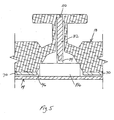
Fig. 5 is a fragmentary cross-sectional view of an analog stick control suitable for use in any one of the preferred embodiments of the manual controller ofFigs. 1-3 . -
Fig. 6 is a fragmentary cross-sectional view of a foam rubber exoskeleton in the form of a multi-layered structure. -
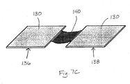
Fig. 7A shows a rigid printed circuit board,Figs. 7B-1 and 7B-2 show a flexible printed circuit board on a substrate in respective unflexed and flexed states, andFig. 7C shows the rigid printed circuit board ofFig. 7A subdivided into separate component parts interconnected by wiring or other communication cabling. -
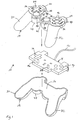
Fig. 1 is an exploded view of a first preferred embodiment of amanual controller 10 that is detachably connected by acable 12 to a computing device (not shown) for manipulating images or symbols on a display associated with the computing device. Although this embodiment is equipped withcable 12,manual controller 10 may also operate with a computing device through a wireless communication link.Manual controller 10 includes aninternal electronics assembly 14 housed within aninterior region 16 of anexoskeleton 18 formed of foam rubber. The foam rubber material is preferably medium-to-high density polyurethane exhibiting flexibility properties, such as those of the foam rubber used in NERF toy products. In the first preferred embodiment,manual controller 10 is assembled by placinginternal electronics assembly 14 between anupper exoskeleton section 22 and alower exoskeleton section 24. Upper andlower exoskeleton sections internal electronics assembly 14. - As shown in
Fig. 1 ,exoskeleton 18 has a left-hand grip 30 and arighthand grip 32 for two-handed gripping by a user. A left-side control pad 34 including fourpressable control members 36, left-sideanalog stick control 38, and front left-side control button 60 are positioned for access by digits of the user's left hand; and a right-side control pad 44 including fourcontrol buttons 46, right-sideanalog stick control 48, and front right-side control button 50 are positioned for access by digits of the user's right hand. A mode selection switch 60,mode indicator 62,selection button 64, and start button 66 are positioned betweenhand grips - In this embodiment, the total surface area of
exoskeleton 18 is covered in foam rubber. The surface areas of these control actuators are perforce covered in foam, thereby rendering them surface control actuators. The control actuator surfaces are preferably made of relatively thin foam rubber, with the button and analog stick control components held in place by a plastic plate 70 (Figs. 4 and5 ) and projecting into recesses in corresponding locations of the control actuator surfaces.Internal electronics assembly 14 includes the actual electronic circuits, controls, and corresponding switch elements, includingswitch elements respective control pads exoskeleton 18. -
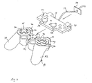
Figs. 2 and3 are respective second and third preferred embodiments ofmanual controller 10, in whichfoam rubber exoskeleton 18 is formed in one piece.Internal electronics assembly 14 is inserted through an opening 76 in the front side ofexoskeleton 18 and force fit intointerior region 16, enabled by the elastic properties of the foam rubber-material defining its boundaries.Internal electronics assembly 14 is glued in place on its side and bottom surfaces, and afoam rubber plate 78 through whichcable 12 passes is glued to cover opening 76. The second and third preferred embodiments exhibit waterproof properties and no seams. The second preferred embodiment shown inFig. 2 has tallanalog stick controls internal electronics assembly 14. The third preferred embodiment shown inFig. 3 has a separate, shaped foam rubber piece 84 that fits overanalog sticks analog stick controls -
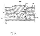
Fig. 4A shows acontrol button 90 that is suitable for use as any one of the control buttons described above with reference toFig. 1 .Control button 90 includes a buttontop portion 92 from which apin 94 downwardly depends through anaperture 96 inplate 70 to contact aswitch contact pad 98 ofinternal electronics assembly 14. Acoil spring 100 positioned between and resting against a bottom surface 102 of buttontop portion 92 andtop surface 104 ofplate 70 functions as a biasing mechanism to keepcontrol button 90 elevated at a nominal distance fromplate 70 in the absence of user applied contact force.Coil spring 100 causescontrol button 90 to apply pressure to the region ofexoskeleton 18 above it, thereby makingcontrol button 90 feel firm to the user. -
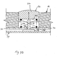
Fig. 4B shows a modification ofFig. 4A in that the region offoam rubber exoskeleton 18 coveringcontrol button 90 is removed to expose buttontop portion 92. Removal of this region of foam rubber can be desirable for certain buttons to increase button reaction time for applications, such as games, requiring buttons exhibiting fast repeat action. Certain buttons for which reaction time is not important, such as a start button, may be covered by foam rubber. Moreover, buttontop portion 92 may be made of hard plastic or impact resistant material. -
Fig. 5 shows ananalog stick control 110 that is suitable for use as one ofanalog stick controls pin 112 matably connects with a relatively shortanalog stick stub 114 projecting upwardly from a raisedportion 116 ofinternal electronics assembly 14. The matable connection can be of conventional plug and socket design secured in place by bonding material, such as glue. - The surface profile of
upper exoskeleton section 22 can be envisioned by inverting it and placing all control actuators includingcontrol buttons 90 and analog stick controls 110 into recesses that form exoskeleton actuator cavities.Coil springs 100 are positioned at the appropriate places forcontrol buttons 90. Asingle plate 70 havingapertures 96 appropriately located to provide passage ofpush pins 94 andanalog sticks internal electronics assembly 14 maintains the placement of the control actuators. - Skilled persons will appreciate that the control actuators can be housed in
internal electronics assembly 14, instead of secured in place insideexoskeleton 18. Control actuators not covered by foam rubber would be exposed through corresponding holes inexoskeleton 18. -
Fig. 6 is a fragmentary cross-sectional view offoam rubber exoskeleton 18 in an alternative form as amulti-layered structure 120, in which an inside core layer 122 separates an upperexternal layer 124 and a lowerexternal layer 126.Internal electronics assembly 14 fits inside core layer 122. All layers ofmulti-layered structure 120 are preferably made of foam rubber, withexternal layers -
Internal electronics assembly 14 itself is preferably encased in a hard plastic housing and includes a rigid printedcircuit board 130, which is shown inFig. 7A .Figs. 7B-1 and 7B-2 show flexible printedcircuit board 132 supported on asubstrate 134 to provide a substitute implementation ofinternal electronics assembly 14 having sufficient rigidity that enables actuation of the control actuators when manipulated by a user.Figs. 7B-1 and 7B-2 show printedcircuit board 132 andsubstrate 134 in respective unflexed and flexed states. The electronic circuit components, controls, and switch elements included ininternal electronics assembly 14 are mounted on a surface of printedcircuit board 132.Fig. 7C shows that rigid printedcircuit board 130 can be divided intoseparate component parts other communication cabling 140. Skilled persons will appreciate that flexible printedcircuit board 132 supported onsubstrate 134 may also be subdivided into component parts and interconnected by cabling. - It will be obvious to those having skill in the art that many changes may be made to the details of the above-described embodiments without departing from the underlying principles of the invention. For example,
exoskeleton 18 can be provided with openings to house or display light-emitting diodes, electroluminescent devices, or other forms of internal lighting. The scope of the present invention should, therefore, be determined only by the following claims.
Claims (22)
- A damage resistant manual controller for manipulating images or symbols on a display, characterised by
a foam rubber housing (18) directly supporting an internal electronics assembly (14), the internal electronics assembly operatively connected to control actuators (36,46) and including electrical components that cooperate with the control actuators to produce signals for manipulating images or symbols on the display, and the control actuators being positioned for direct or indirect tactile manipulation by a user to cause production of the signals. - The manual controller of claim 1, in which the foam rubber housing covers the control actuators and thereby forms surface actuators that a user indirectly actuates by tactile manipulation of surface regions of the housing covering the control buttons.
- The manual controller of claim 1, in which the foam rubber housing is formed of upper and lower sections bonded together to form a unitary foam casing.
- The manual controller of claim 1, in which the foam rubber housing is formed of medium-to-high density polyurethane foam.
- The manual controller of claim 1, in which the foam rubber housing is at least in part formed as a multi-layered structure comprising an inside core layer and an outside surface layer, the inside core layer exhibiting higher density properties than those of the outside surface layer to provide differences in stability and tactility.
- The manual controller of claim 1, in which the foam rubber housing is formed as an integral structure having an opening configured to facilitate insertion of the electronics assembly into the interior region.
- The manual controller of claim 6, further comprising a foam rubber cover sized to close the opening.
- The manual controller of claim 1, in which the electronics assembly is encased in hard plastic.
- The manual controller of claim 1, in which the control actuators include analog stick controls that are operatively connected to the electronics assembly.
- The manual controller of claim 9, in which the analog stick controls are pre-installed with foam rubber formed to the electronics assembly.
- The manual controller of claim 9, in which the analog stick controls are mounted on a foam rubber base and figured for installation on the electronics assembly.
- The manual controller of claim 1, in which the foam rubber housing covers one or more of the control actuators, and each covered control actuator comprises an actuator assembly that includes a pin and a plate portion on which the foam rubber housing rests and through which an aperture is located to cause the pin to contact the internal electronics assembly.
- The manual controller of claim 12, in which the actuator assembly includes a button top portion from which the pin depends, and further comprising a biasing member providing a nominal separation distance between the button top portion and the plate portion in the absence of external contact force applied to the button top portion.
- The manual controller of claim 13, in which the biasing member includes a spring.
- The manual controller of claim 12, in which the pin has a top and that fits into a recess in the foam rubber housing.
- The manual controller of claim 12, further comprising an analog stick stub extending from the electronics assembly, and in which the pin has a bottom end that forms a matable connection with the analog stick stub.
- The manual controller of claim 1, in which the electronics assembly includes a flexible printed circuit board supported on a substrate to provide sufficient rigidity to enable operation of the control actuators when manipulated by a user.
- The manual controller of claim 17, in which the flexible printed circuit board supported on a substrate is divided into multiple separate parts interconnected by communication cabling.
- The manual controller of claim 1, in which the electronics assembly includes a rigid printed circuit board unsupported by a substrate to enable operation of the control actuators when manipulated by a user.
- The manual controller of claim 19, in which the rigid printed circuit board is divided into multiple separate parts interconnected by communication cabling.
- The manual controller of claim 1, in which the housing includes an outwardly extending portion having an interior and located for manual contact by the user, and further comprising an elongated member that extends in a direction away from the internal electronics assembly and into the interior of the outwardly extending portion.
- The manual controller of claim 1, in which the electronics assembly is encased in a housing made of hard material.
Applications Claiming Priority (2)
| Application Number | Priority Date | Filing Date | Title |
|---|---|---|---|
| US60334904P | 2004-08-20 | 2004-08-20 | |
| PCT/US2005/029587 WO2006023746A2 (en) | 2004-08-20 | 2005-08-19 | Control device made of impact resistant material |
Publications (3)
| Publication Number | Publication Date |
|---|---|
| EP1784846A2 EP1784846A2 (en) | 2007-05-16 |
| EP1784846A4 EP1784846A4 (en) | 2007-10-03 |
| EP1784846B1 true EP1784846B1 (en) | 2009-03-18 |
Family
ID=35968213
Family Applications (1)
| Application Number | Title | Priority Date | Filing Date |
|---|---|---|---|
| EP05788831A Not-in-force EP1784846B1 (en) | 2004-08-20 | 2005-08-19 | Control device made of impact resistant material |
Country Status (12)
| Country | Link |
|---|---|
| US (4) | US7582017B2 (en) |
| EP (1) | EP1784846B1 (en) |
| JP (1) | JP5162241B2 (en) |
| KR (1) | KR101215005B1 (en) |
| CN (1) | CN101023503B (en) |
| AT (1) | ATE426241T1 (en) |
| AU (1) | AU2005277279B8 (en) |
| CA (1) | CA2628320C (en) |
| DE (1) | DE602005013392D1 (en) |
| ES (1) | ES2324109T3 (en) |
| MX (1) | MX2007002028A (en) |
| WO (1) | WO2006023746A2 (en) |
Families Citing this family (10)
| Publication number | Priority date | Publication date | Assignee | Title |
|---|---|---|---|---|
| US20070242036A1 (en) * | 2006-04-17 | 2007-10-18 | Microsoft Corporation | Dual control data entry |
| US7837559B2 (en) * | 2007-05-10 | 2010-11-23 | Michael Kidakarn | Game controller with internal enclosure |
| US8991930B2 (en) * | 2008-09-22 | 2015-03-31 | Johnson Controls Technology Company | Closed cell foam vehicle interior component and method of making same |
| US8267787B2 (en) * | 2009-01-16 | 2012-09-18 | Sony Computer Entertainment Inc. | Controller and portable electronic apparatus |
| US8708825B2 (en) * | 2011-04-25 | 2014-04-29 | Rhode Island Hospital | Device controller with conformable fitting system |
| JP5346366B2 (en) * | 2011-12-02 | 2013-11-20 | 株式会社テックアーツ | Game controller and game program |
| US20150157949A1 (en) * | 2012-12-27 | 2015-06-11 | Robert Gordon Durling, JR. | Gaming controller thumb glove interface |
| US9874945B2 (en) | 2014-02-13 | 2018-01-23 | Microsoft Technology Licensing, Llc | Low-profile pointing stick |
| US10627918B2 (en) | 2014-02-13 | 2020-04-21 | Microsoft Technology Licensing, Llc | Low-profile pointing stick |
| US10528155B2 (en) * | 2014-02-13 | 2020-01-07 | Microsoft Technology Licensing, Llc | Low-profile pointing stick |
Family Cites Families (49)
| Publication number | Priority date | Publication date | Assignee | Title |
|---|---|---|---|---|
| JPS5829862Y2 (en) * | 1978-11-13 | 1983-06-30 | 松下電工株式会社 | Keyboard switch operation panel |
| US4422640A (en) * | 1982-07-06 | 1983-12-27 | Tamarkin Michael J | Video game control unit and lap board holder therefor |
| JPS62188028U (en) * | 1986-05-22 | 1987-11-30 | ||
| JPH0354906Y2 (en) * | 1986-10-24 | 1991-12-05 | ||
| US4769517A (en) | 1987-04-13 | 1988-09-06 | Swinney Carl M | Joystick switch assembly |
| US4762227A (en) * | 1987-11-19 | 1988-08-09 | Patterson Robert C | Resilient housing for remote controllers |
| JP2594077B2 (en) * | 1987-12-08 | 1997-03-26 | 松下電器産業株式会社 | Audio equipment |
| US4824059A (en) | 1988-02-01 | 1989-04-25 | Butler Les I | Cushioning device for remote control television equipment, and assembly thereof |
| US5181024A (en) | 1988-11-30 | 1993-01-19 | Kabushiki Kaisha Toshiba | Book type wireless remote control apparatus |
| US4925149A (en) | 1989-04-21 | 1990-05-15 | Difrancesca Peter | Shock absorbing unit |
| US5012513A (en) * | 1989-08-01 | 1991-04-30 | George L. Dale | Telephone handset cover |
| US6102802A (en) * | 1997-10-01 | 2000-08-15 | Armstrong; Brad A. | Game controller with analog pressure sensor(s) |
| JPH0656831U (en) * | 1992-12-25 | 1994-08-05 | 川崎製鉄株式会社 | PC input device |
| WO1994019735A1 (en) | 1993-02-20 | 1994-09-01 | Nbb Nachrichtentechnik Gmbh & Co. Kg | Manual controller with control lever |
| US5741182A (en) | 1994-06-17 | 1998-04-21 | Sports Sciences, Inc. | Sensing spatial movement |
| JPH0818637A (en) * | 1994-06-27 | 1996-01-19 | Ebisu Kasei:Kk | Case for portable telephone |
| US5820462A (en) * | 1994-08-02 | 1998-10-13 | Nintendo Company Ltd. | Manipulator for game machine |
| US5648757A (en) * | 1994-10-24 | 1997-07-15 | Vernace; Salvatore J. | Remote control protective holder and detection device |
| JPH09271080A (en) * | 1996-03-29 | 1997-10-14 | Mitsumi Electric Co Ltd | Remote controller |
| JPH09306271A (en) * | 1996-05-07 | 1997-11-28 | Matsushita Electric Ind Co Ltd | Cursor manual operating device |
| US6259433B1 (en) * | 1996-05-14 | 2001-07-10 | Norman H. Meyers | Digital optical joystick with mechanically magnified resolution |
| JPH09319515A (en) * | 1996-05-28 | 1997-12-12 | Eiji Takahashi | Mouse for computer input and cover for the same |
| US5930356A (en) * | 1996-07-02 | 1999-07-27 | Harrison; Mark R. | Telephone handset cover |
| US5993463A (en) | 1997-05-15 | 1999-11-30 | Regents Of The University Of Minnesota | Remote actuation of trajectory guide |
| US5883690A (en) * | 1997-05-30 | 1999-03-16 | Z-Products | Joystick adapter for a directional keypad on a game controller |
| US5880418A (en) | 1997-11-20 | 1999-03-09 | Livesay; L. D. | Method and apparatus for a multi-function manual controller |
| US6120025A (en) * | 1998-04-14 | 2000-09-19 | Hughes, Iv; Richard James-Patrick | Controller grip for a video game machine |
| JP3816664B2 (en) * | 1998-04-28 | 2006-08-30 | アルプス電気株式会社 | Multidirectional switch and electronic device using the multidirectional switch |
| US6241247B1 (en) * | 1998-05-28 | 2001-06-05 | Aaron Sternberg | Remote control with ventilation holes |
| JP2000029624A (en) * | 1998-07-09 | 2000-01-28 | Yayoi:Kk | Mouse cover pad |
| JP2000112653A (en) * | 1998-09-30 | 2000-04-21 | Sanwa Supply Kk | Gel-charged mouse and gel-charged cover for mouse |
| US6110073A (en) * | 1999-02-03 | 2000-08-29 | Tread Pad Partners, Llc | Physical fitness device |
| US6545667B1 (en) | 1999-08-23 | 2003-04-08 | David M. Lilenfield | Apparatus for a convenient and comfortable cursor control device |
| JP2001143556A (en) * | 1999-11-12 | 2001-05-25 | Sony Computer Entertainment Inc | Operating device |
| JP2001318758A (en) * | 2000-03-03 | 2001-11-16 | Sony Computer Entertainment Inc | Operation unit and signal output adjustment method for the unit |
| JP3073061U (en) * | 2000-05-09 | 2000-11-14 | 國城 曾 | Remote control protection cover with aesthetics and protection |
| US6975898B2 (en) | 2000-06-19 | 2005-12-13 | University Of Washington | Medical imaging, diagnosis, and therapy using a scanning single optical fiber system |
| US6459420B1 (en) * | 2000-06-26 | 2002-10-01 | Curtis James Harris | Ergonomical joystick design or attachment |
| JP2002196858A (en) * | 2000-12-25 | 2002-07-12 | Sony Corp | Electronic equipment |
| JP2002260493A (en) * | 2001-03-06 | 2002-09-13 | Alps Electric Co Ltd | Four-directional switch device |
| US6688259B2 (en) * | 2001-05-31 | 2004-02-10 | Wendy Axel | Handle with grip for comfortably holding articles by hand |
| US20020180148A1 (en) | 2001-06-01 | 2002-12-05 | John Koziel | Remote control with hand and finger cushions |
| US20030127345A1 (en) * | 2002-01-10 | 2003-07-10 | Zuleta Victor H. | Protective cover for remote control devices |
| US7297061B2 (en) * | 2002-12-16 | 2007-11-20 | Mattel, Inc. | Game controller having multiple operation modes |
| US20050075172A1 (en) * | 2003-10-02 | 2005-04-07 | Coleman Jourdon G. S. | Cover for a video game controller |
| JP3102907U (en) * | 2004-01-21 | 2004-07-22 | ▲黄▼賢達 | Game console controller with buffer function |
| US7167159B2 (en) * | 2004-07-01 | 2007-01-23 | Geltabz, Inc. | Joystick cover |
| US20060258458A1 (en) * | 2005-05-13 | 2006-11-16 | Addington David R | System and method for interfacing a simulation device with a gaming device |
| US7762553B2 (en) * | 2006-11-25 | 2010-07-27 | Harris Curtis J | Form-fitting electronic game controller cover |
-
2005
- 2005-08-19 CN CN2005800305117A patent/CN101023503B/en not_active Expired - Fee Related
- 2005-08-19 CA CA2628320A patent/CA2628320C/en not_active Expired - Fee Related
- 2005-08-19 ES ES05788831T patent/ES2324109T3/en active Active
- 2005-08-19 KR KR1020077003785A patent/KR101215005B1/en not_active IP Right Cessation
- 2005-08-19 AT AT05788831T patent/ATE426241T1/en not_active IP Right Cessation
- 2005-08-19 AU AU2005277279A patent/AU2005277279B8/en not_active Ceased
- 2005-08-19 US US11/587,503 patent/US7582017B2/en not_active Expired - Fee Related
- 2005-08-19 DE DE602005013392T patent/DE602005013392D1/en active Active
- 2005-08-19 EP EP05788831A patent/EP1784846B1/en not_active Not-in-force
- 2005-08-19 WO PCT/US2005/029587 patent/WO2006023746A2/en active Application Filing
- 2005-08-19 MX MX2007002028A patent/MX2007002028A/en active IP Right Grant
- 2005-08-19 JP JP2007528048A patent/JP5162241B2/en not_active Expired - Fee Related
-
2009
- 2009-06-16 US US12/485,738 patent/US7785202B2/en not_active Expired - Fee Related
-
2010
- 2010-08-26 US US12/869,052 patent/US8439754B2/en not_active Expired - Fee Related
-
2013
- 2013-05-13 US US13/893,032 patent/US20130249795A1/en not_active Abandoned
Also Published As
| Publication number | Publication date |
|---|---|
| US7582017B2 (en) | 2009-09-01 |
| MX2007002028A (en) | 2007-10-11 |
| CA2628320A1 (en) | 2006-03-02 |
| ATE426241T1 (en) | 2009-04-15 |
| US20080032795A1 (en) | 2008-02-07 |
| AU2005277279B8 (en) | 2011-12-08 |
| KR20070057802A (en) | 2007-06-07 |
| JP2008511056A (en) | 2008-04-10 |
| ES2324109T3 (en) | 2009-07-30 |
| WO2006023746A3 (en) | 2006-10-12 |
| EP1784846A4 (en) | 2007-10-03 |
| US20100323796A1 (en) | 2010-12-23 |
| US7785202B2 (en) | 2010-08-31 |
| WO2006023746A2 (en) | 2006-03-02 |
| DE602005013392D1 (en) | 2009-04-30 |
| US20130249795A1 (en) | 2013-09-26 |
| CN101023503B (en) | 2012-07-25 |
| AU2005277279B2 (en) | 2011-10-27 |
| JP5162241B2 (en) | 2013-03-13 |
| AU2005277279A2 (en) | 2006-03-02 |
| US8439754B2 (en) | 2013-05-14 |
| AU2005277279A1 (en) | 2006-03-02 |
| CA2628320C (en) | 2014-04-22 |
| EP1784846A2 (en) | 2007-05-16 |
| KR101215005B1 (en) | 2012-12-24 |
| US20090253510A1 (en) | 2009-10-08 |
| CN101023503A (en) | 2007-08-22 |
Similar Documents
| Publication | Publication Date | Title |
|---|---|---|
| EP1784846B1 (en) | Control device made of impact resistant material | |
| US7916002B2 (en) | Haptic operative user interface input apparatus | |
| US7880106B2 (en) | Switch assembly constructions | |
| US10049829B2 (en) | Switch device | |
| JP2008511056A5 (en) | ||
| US9685093B2 (en) | Customizable wireless education or occupational therapy tool having a switch unit and a transmitter unit | |
| US7943877B2 (en) | Switch structure having display and playback device | |
| KR200400393Y1 (en) | Keypad with movable key button | |
| JP2018125266A (en) | Handle switch | |
| US9024791B2 (en) | Input device with rotary wheel | |
| KR100821250B1 (en) | Button structure creating unique operating signal and portable audio player using it | |
| JP4449541B2 (en) | Key unit, key device and electronic device | |
| US20110187575A1 (en) | Remote control transmitter | |
| US20050255917A1 (en) | Direction controller with separating direction control keys | |
| CN107850949A (en) | Pressable key and keyboard | |
| JP2011160389A (en) | Remote control transmitter |
Legal Events
| Date | Code | Title | Description |
|---|---|---|---|
| PUAI | Public reference made under article 153(3) epc to a published international application that has entered the european phase |
Free format text: ORIGINAL CODE: 0009012 |
|
| 17P | Request for examination filed |
Effective date: 20070314 |
|
| AK | Designated contracting states |
Kind code of ref document: A2 Designated state(s): AT BE BG CH CY CZ DE DK EE ES FI FR GB GR HU IE IS IT LI LT LU LV MC NL PL PT RO SE SI SK TR |
|
| RIC1 | Information provided on ipc code assigned before grant |
Ipc: G05G 9/047 20060101ALI20070710BHEP Ipc: H01H 25/04 20060101AFI20070710BHEP |
|
| A4 | Supplementary search report drawn up and despatched |
Effective date: 20070905 |
|
| DAX | Request for extension of the european patent (deleted) | ||
| 17Q | First examination report despatched |
Effective date: 20071123 |
|
| GRAP | Despatch of communication of intention to grant a patent |
Free format text: ORIGINAL CODE: EPIDOSNIGR1 |
|
| GRAS | Grant fee paid |
Free format text: ORIGINAL CODE: EPIDOSNIGR3 |
|
| GRAA | (expected) grant |
Free format text: ORIGINAL CODE: 0009210 |
|
| AK | Designated contracting states |
Kind code of ref document: B1 Designated state(s): AT BE BG CH CY CZ DE DK EE ES FI FR GB GR HU IE IS IT LI LT LU LV MC NL PL PT RO SE SI SK TR |
|
| REG | Reference to a national code |
Ref country code: GB Ref legal event code: FG4D |
|
| REG | Reference to a national code |
Ref country code: CH Ref legal event code: EP |
|
| REG | Reference to a national code |
Ref country code: IE Ref legal event code: FG4D |
|
| REF | Corresponds to: |
Ref document number: 602005013392 Country of ref document: DE Date of ref document: 20090430 Kind code of ref document: P |
|
| REG | Reference to a national code |
Ref country code: SE Ref legal event code: TRGR |
|
| REG | Reference to a national code |
Ref country code: ES Ref legal event code: FG2A Ref document number: 2324109 Country of ref document: ES Kind code of ref document: T3 |
|
| PG25 | Lapsed in a contracting state [announced via postgrant information from national office to epo] |
Ref country code: NL Free format text: LAPSE BECAUSE OF FAILURE TO SUBMIT A TRANSLATION OF THE DESCRIPTION OR TO PAY THE FEE WITHIN THE PRESCRIBED TIME-LIMIT Effective date: 20090318 Ref country code: SI Free format text: LAPSE BECAUSE OF FAILURE TO SUBMIT A TRANSLATION OF THE DESCRIPTION OR TO PAY THE FEE WITHIN THE PRESCRIBED TIME-LIMIT Effective date: 20090318 Ref country code: LT Free format text: LAPSE BECAUSE OF FAILURE TO SUBMIT A TRANSLATION OF THE DESCRIPTION OR TO PAY THE FEE WITHIN THE PRESCRIBED TIME-LIMIT Effective date: 20090318 Ref country code: FI Free format text: LAPSE BECAUSE OF FAILURE TO SUBMIT A TRANSLATION OF THE DESCRIPTION OR TO PAY THE FEE WITHIN THE PRESCRIBED TIME-LIMIT Effective date: 20090318 |
|
| PG25 | Lapsed in a contracting state [announced via postgrant information from national office to epo] |
Ref country code: LV Free format text: LAPSE BECAUSE OF FAILURE TO SUBMIT A TRANSLATION OF THE DESCRIPTION OR TO PAY THE FEE WITHIN THE PRESCRIBED TIME-LIMIT Effective date: 20090318 Ref country code: PL Free format text: LAPSE BECAUSE OF FAILURE TO SUBMIT A TRANSLATION OF THE DESCRIPTION OR TO PAY THE FEE WITHIN THE PRESCRIBED TIME-LIMIT Effective date: 20090318 Ref country code: AT Free format text: LAPSE BECAUSE OF FAILURE TO SUBMIT A TRANSLATION OF THE DESCRIPTION OR TO PAY THE FEE WITHIN THE PRESCRIBED TIME-LIMIT Effective date: 20090318 |
|
| NLV1 | Nl: lapsed or annulled due to failure to fulfill the requirements of art. 29p and 29m of the patents act | ||
| PG25 | Lapsed in a contracting state [announced via postgrant information from national office to epo] |
Ref country code: BE Free format text: LAPSE BECAUSE OF FAILURE TO SUBMIT A TRANSLATION OF THE DESCRIPTION OR TO PAY THE FEE WITHIN THE PRESCRIBED TIME-LIMIT Effective date: 20090318 |
|
| PG25 | Lapsed in a contracting state [announced via postgrant information from national office to epo] |
Ref country code: PT Free format text: LAPSE BECAUSE OF FAILURE TO SUBMIT A TRANSLATION OF THE DESCRIPTION OR TO PAY THE FEE WITHIN THE PRESCRIBED TIME-LIMIT Effective date: 20090826 Ref country code: EE Free format text: LAPSE BECAUSE OF FAILURE TO SUBMIT A TRANSLATION OF THE DESCRIPTION OR TO PAY THE FEE WITHIN THE PRESCRIBED TIME-LIMIT Effective date: 20090318 Ref country code: CZ Free format text: LAPSE BECAUSE OF FAILURE TO SUBMIT A TRANSLATION OF THE DESCRIPTION OR TO PAY THE FEE WITHIN THE PRESCRIBED TIME-LIMIT Effective date: 20090318 |
|
| PG25 | Lapsed in a contracting state [announced via postgrant information from national office to epo] |
Ref country code: SK Free format text: LAPSE BECAUSE OF FAILURE TO SUBMIT A TRANSLATION OF THE DESCRIPTION OR TO PAY THE FEE WITHIN THE PRESCRIBED TIME-LIMIT Effective date: 20090318 Ref country code: RO Free format text: LAPSE BECAUSE OF FAILURE TO SUBMIT A TRANSLATION OF THE DESCRIPTION OR TO PAY THE FEE WITHIN THE PRESCRIBED TIME-LIMIT Effective date: 20090318 Ref country code: IS Free format text: LAPSE BECAUSE OF FAILURE TO SUBMIT A TRANSLATION OF THE DESCRIPTION OR TO PAY THE FEE WITHIN THE PRESCRIBED TIME-LIMIT Effective date: 20090718 |
|
| PLBE | No opposition filed within time limit |
Free format text: ORIGINAL CODE: 0009261 |
|
| STAA | Information on the status of an ep patent application or granted ep patent |
Free format text: STATUS: NO OPPOSITION FILED WITHIN TIME LIMIT |
|
| PG25 | Lapsed in a contracting state [announced via postgrant information from national office to epo] |
Ref country code: BG Free format text: LAPSE BECAUSE OF FAILURE TO SUBMIT A TRANSLATION OF THE DESCRIPTION OR TO PAY THE FEE WITHIN THE PRESCRIBED TIME-LIMIT Effective date: 20090618 Ref country code: DK Free format text: LAPSE BECAUSE OF FAILURE TO SUBMIT A TRANSLATION OF THE DESCRIPTION OR TO PAY THE FEE WITHIN THE PRESCRIBED TIME-LIMIT Effective date: 20090318 |
|
| 26N | No opposition filed |
Effective date: 20091221 |
|
| PG25 | Lapsed in a contracting state [announced via postgrant information from national office to epo] |
Ref country code: MC Free format text: LAPSE BECAUSE OF NON-PAYMENT OF DUE FEES Effective date: 20090831 |
|
| REG | Reference to a national code |
Ref country code: CH Ref legal event code: PL |
|
| PG25 | Lapsed in a contracting state [announced via postgrant information from national office to epo] |
Ref country code: CH Free format text: LAPSE BECAUSE OF NON-PAYMENT OF DUE FEES Effective date: 20090831 Ref country code: LI Free format text: LAPSE BECAUSE OF NON-PAYMENT OF DUE FEES Effective date: 20090831 |
|
| PG25 | Lapsed in a contracting state [announced via postgrant information from national office to epo] |
Ref country code: GR Free format text: LAPSE BECAUSE OF FAILURE TO SUBMIT A TRANSLATION OF THE DESCRIPTION OR TO PAY THE FEE WITHIN THE PRESCRIBED TIME-LIMIT Effective date: 20090619 |
|
| PG25 | Lapsed in a contracting state [announced via postgrant information from national office to epo] |
Ref country code: LU Free format text: LAPSE BECAUSE OF NON-PAYMENT OF DUE FEES Effective date: 20090819 |
|
| PG25 | Lapsed in a contracting state [announced via postgrant information from national office to epo] |
Ref country code: HU Free format text: LAPSE BECAUSE OF FAILURE TO SUBMIT A TRANSLATION OF THE DESCRIPTION OR TO PAY THE FEE WITHIN THE PRESCRIBED TIME-LIMIT Effective date: 20090919 |
|
| PG25 | Lapsed in a contracting state [announced via postgrant information from national office to epo] |
Ref country code: TR Free format text: LAPSE BECAUSE OF FAILURE TO SUBMIT A TRANSLATION OF THE DESCRIPTION OR TO PAY THE FEE WITHIN THE PRESCRIBED TIME-LIMIT Effective date: 20090318 |
|
| PG25 | Lapsed in a contracting state [announced via postgrant information from national office to epo] |
Ref country code: CY Free format text: LAPSE BECAUSE OF FAILURE TO SUBMIT A TRANSLATION OF THE DESCRIPTION OR TO PAY THE FEE WITHIN THE PRESCRIBED TIME-LIMIT Effective date: 20090318 |
|
| PGFP | Annual fee paid to national office [announced via postgrant information from national office to epo] |
Ref country code: DE Payment date: 20130902 Year of fee payment: 9 Ref country code: ES Payment date: 20130828 Year of fee payment: 9 Ref country code: IE Payment date: 20130829 Year of fee payment: 9 Ref country code: SE Payment date: 20130826 Year of fee payment: 9 |
|
| PGFP | Annual fee paid to national office [announced via postgrant information from national office to epo] |
Ref country code: GB Payment date: 20130827 Year of fee payment: 9 Ref country code: FR Payment date: 20130826 Year of fee payment: 9 |
|
| PGFP | Annual fee paid to national office [announced via postgrant information from national office to epo] |
Ref country code: IT Payment date: 20130828 Year of fee payment: 9 |
|
| REG | Reference to a national code |
Ref country code: DE Ref legal event code: R119 Ref document number: 602005013392 Country of ref document: DE |
|
| REG | Reference to a national code |
Ref country code: SE Ref legal event code: EUG |
|
| GBPC | Gb: european patent ceased through non-payment of renewal fee |
Effective date: 20140819 |
|
| PG25 | Lapsed in a contracting state [announced via postgrant information from national office to epo] |
Ref country code: IT Free format text: LAPSE BECAUSE OF NON-PAYMENT OF DUE FEES Effective date: 20140819 |
|
| REG | Reference to a national code |
Ref country code: IE Ref legal event code: MM4A |
|
| REG | Reference to a national code |
Ref country code: DE Ref legal event code: R119 Ref document number: 602005013392 Country of ref document: DE Effective date: 20150303 |
|
| PG25 | Lapsed in a contracting state [announced via postgrant information from national office to epo] |
Ref country code: SE Free format text: LAPSE BECAUSE OF NON-PAYMENT OF DUE FEES Effective date: 20140820 |
|
| REG | Reference to a national code |
Ref country code: FR Ref legal event code: ST Effective date: 20150430 |
|
| PG25 | Lapsed in a contracting state [announced via postgrant information from national office to epo] |
Ref country code: DE Free format text: LAPSE BECAUSE OF NON-PAYMENT OF DUE FEES Effective date: 20150303 Ref country code: GB Free format text: LAPSE BECAUSE OF NON-PAYMENT OF DUE FEES Effective date: 20140819 |
|
| PG25 | Lapsed in a contracting state [announced via postgrant information from national office to epo] |
Ref country code: FR Free format text: LAPSE BECAUSE OF NON-PAYMENT OF DUE FEES Effective date: 20140901 Ref country code: IE Free format text: LAPSE BECAUSE OF NON-PAYMENT OF DUE FEES Effective date: 20140819 |
|
| REG | Reference to a national code |
Ref country code: ES Ref legal event code: FD2A Effective date: 20150925 |
|
| PG25 | Lapsed in a contracting state [announced via postgrant information from national office to epo] |
Ref country code: ES Free format text: LAPSE BECAUSE OF NON-PAYMENT OF DUE FEES Effective date: 20140820 |