EP1783573A2 - Apparatus and method for controlling camera of robot cleaner - Google Patents
Apparatus and method for controlling camera of robot cleaner Download PDFInfo
- Publication number
- EP1783573A2 EP1783573A2 EP06122977A EP06122977A EP1783573A2 EP 1783573 A2 EP1783573 A2 EP 1783573A2 EP 06122977 A EP06122977 A EP 06122977A EP 06122977 A EP06122977 A EP 06122977A EP 1783573 A2 EP1783573 A2 EP 1783573A2
- Authority
- EP
- European Patent Office
- Prior art keywords
- camera
- robot cleaner
- axis
- image
- driver
- Prior art date
- Legal status (The legal status is an assumption and is not a legal conclusion. Google has not performed a legal analysis and makes no representation as to the accuracy of the status listed.)
- Granted
Links
- 238000000034 method Methods 0.000 title claims abstract description 22
- 238000012545 processing Methods 0.000 claims abstract description 7
- 238000010276 construction Methods 0.000 description 13
- 238000004091 panning Methods 0.000 description 10
- 230000006870 function Effects 0.000 description 6
- 238000004140 cleaning Methods 0.000 description 5
- 238000004519 manufacturing process Methods 0.000 description 5
- 238000013459 approach Methods 0.000 description 2
- 230000008901 benefit Effects 0.000 description 2
- 238000001514 detection method Methods 0.000 description 2
- 238000010586 diagram Methods 0.000 description 2
- 238000012790 confirmation Methods 0.000 description 1
- 238000012986 modification Methods 0.000 description 1
- 230000004048 modification Effects 0.000 description 1
Images

Classifications
-
- G—PHYSICS
- G05—CONTROLLING; REGULATING
- G05D—SYSTEMS FOR CONTROLLING OR REGULATING NON-ELECTRIC VARIABLES
- G05D1/00—Control of position, course or altitude of land, water, air, or space vehicles, e.g. automatic pilot
- G05D1/02—Control of position or course in two dimensions
- G05D1/021—Control of position or course in two dimensions specially adapted to land vehicles
- G05D1/0231—Control of position or course in two dimensions specially adapted to land vehicles using optical position detecting means
- G05D1/0246—Control of position or course in two dimensions specially adapted to land vehicles using optical position detecting means using a video camera in combination with image processing means
-
- A—HUMAN NECESSITIES
- A47—FURNITURE; DOMESTIC ARTICLES OR APPLIANCES; COFFEE MILLS; SPICE MILLS; SUCTION CLEANERS IN GENERAL
- A47L—DOMESTIC WASHING OR CLEANING; SUCTION CLEANERS IN GENERAL
- A47L9/00—Details or accessories of suction cleaners, e.g. mechanical means for controlling the suction or for effecting pulsating action; Storing devices specially adapted to suction cleaners or parts thereof; Carrying-vehicles specially adapted for suction cleaners
- A47L9/28—Installation of the electric equipment, e.g. adaptation or attachment to the suction cleaner; Controlling suction cleaners by electric means
-
- A—HUMAN NECESSITIES
- A47—FURNITURE; DOMESTIC ARTICLES OR APPLIANCES; COFFEE MILLS; SPICE MILLS; SUCTION CLEANERS IN GENERAL
- A47L—DOMESTIC WASHING OR CLEANING; SUCTION CLEANERS IN GENERAL
- A47L11/00—Machines for cleaning floors, carpets, furniture, walls, or wall coverings
-
- A—HUMAN NECESSITIES
- A47—FURNITURE; DOMESTIC ARTICLES OR APPLIANCES; COFFEE MILLS; SPICE MILLS; SUCTION CLEANERS IN GENERAL
- A47L—DOMESTIC WASHING OR CLEANING; SUCTION CLEANERS IN GENERAL
- A47L9/00—Details or accessories of suction cleaners, e.g. mechanical means for controlling the suction or for effecting pulsating action; Storing devices specially adapted to suction cleaners or parts thereof; Carrying-vehicles specially adapted for suction cleaners
- A47L9/009—Carrying-vehicles; Arrangements of trollies or wheels; Means for avoiding mechanical obstacles
-
- A—HUMAN NECESSITIES
- A47—FURNITURE; DOMESTIC ARTICLES OR APPLIANCES; COFFEE MILLS; SPICE MILLS; SUCTION CLEANERS IN GENERAL
- A47L—DOMESTIC WASHING OR CLEANING; SUCTION CLEANERS IN GENERAL
- A47L2201/00—Robotic cleaning machines, i.e. with automatic control of the travelling movement or the cleaning operation
- A47L2201/04—Automatic control of the travelling movement; Automatic obstacle detection
Definitions
- the present invention relates to an apparatus and a method for controlling a camera mounted at a robot cleaner in order to sense obstacles and perform a position compensation, and more particularly, to an apparatus and a method for controlling a camera of a robot cleaner, which photograph a subject to sense obstacles and to photograph a label for a position compensation by moving and controlling one camera mounted at a robot cleaner in two axis directions.
- a conventional robot cleaner may sense cleaning zones or obstacles using a camera.
- Korean patent application No. 1998-23269 discloses a technique, which rotates a camera and a laser beam discharge element at a predetermined angle to photograph an ambient environment of a cleaning zone in which a laser beam point is formed and to detect a pattern of the cleaning zone according to the photographed image.
- Korean patent application No. 2000-68446 discloses a technique for sensing obstacles, which includes a vision camera for emitting a laser to obstacles and detecting a linear beam reflected from the obstacles.
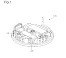
- FIG. 1 is a perspective view for schematically showing a conventional robot cleaner with a camera for position compensation.
- a front camera 110 is installed in front of the robot cleaner.
- the front camera 110 senses whether or not there are obstacles. That is, the front camera 110 photographs a front of the robot cleaner to sense obstacles.
- an upper camera 120 confirms or compensates a position of the robot cleaner. More particularly, the upper camera 120 photographs a predetermined label installed at a ceiling or a wall of an indoor, and confirms or estimates the position of the robot cleaner based on the photographed label.
- the conventional robot cleaner should separately include a camera for sensing obstacles and a camera for confirming a position thereof. That will make a construction of the robot cleaner complicated. Further, a use of a plurality of camera modules boosts manufacturing cost of the robot cleaner.
- Another object of the present invention is to provide an apparatus and a method for controlling a camera of a robot cleaner, which may sense objects existing at different directions by rotating the camera in horizontal and vertical directions.
- a further object of the present invention is to provide an apparatus and a method for controlling a camera of a robot cleaner, which may effectively travel the robot cleaner by repeating a photograph operation for sensing obstacles and confirming a position of the robot cleaner using one camera while the robot cleaner cleans a predetermined zone.
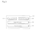
- the above object of the present invention is substantially realized by providing a n apparatus for controlling a camera of a robot cleaner comprising: a first axis driver 310 for driving a camera mounted at the robot cleaner in a first axis direction; a second axis driver 320 for driving the camera in a second axis direction other than the first axis direction; an image processor 330 for receiving and processing an image photographed by the camera; and a control section 340 for controlling the first axis driver and the second axis driver, and controlling a traveling of the robot cleaner based on the image photographed by the camera.
- a method for controlling a camera of a robot cleaner comprising the steps of: (i) initializing a camera mounted at the robot cleaner with an origin; (ii) driving the camera in a first axis direction and photographing a first image by the camera; (iii) driving the camera in a second axis direction other than the first axis direction and photographing a second image by the camera; (iv) receiving and processing the first and second images photographed by the camera; (v) controlling a traveling of the robot cleaner based on the first and second photographed images.
- FIG. 1 is a perspective view for schematically showing a conventional robot cleaner with a camera
- FIG. 2 is a concept view showing an operation principle of a camera mounted at a robot cleaner according to an embodiment of the present invention
- FIG. 3 is a block diagram showing a schematic construction of the robot cleaner according to an embodiment of the present invention.
- FIG. 4a is a concept view showing a schematic construction of a driver for a panning of a camera according to an embodiment of the present invention
- FIG. 4b is a concept view showing a schematic construction of a driver for a tilting of a camera according to an embodiment of the present invention.
- FIG. 5 is a flow chart for illustrating a method for controlling a camera according to an embodiment of the present invention.
- one element when one element is connected to another element, one element may be not only directly connected to another element but also indirectly connected to another element via another element. Further, irrelative elements are omitted for clarity.
- FIG. 2 is a concept view showing an operation principle of a camera mounted at a robot cleaner according to an embodiment of the present invention.
- a camera module mounted at the robot cleaner rotates up and down, and from side to side, to detect or avoid obstacles existing at a front direction or to detect a label installed at a ceiling or a wall in order to recognize a position of the robot cleaner. So as to do this, the camera is installed at a front upper side of the robot cleaner. The camera performs a tilting operation rotating up and down and a panning operation rotating from side to side, to photograph a subject.
- the photographed images are divided and stored according to whether the images are for sensing obstacles or for detecting a label.
- the camera detects presence or absence, distance, and pattern of the obstacles. Because a technique for detecting presence or absence, distance, and pattern of the obstacles using photographed images is well known, a detailed description thereof is omitted.
- the camera detects whether or not there is a corresponding label, or the label is a specific one among various kinds of labels, for example, a label indicating living room, kitchen, sitting room, or a first zone or a second zone of the living room. Because this procedure is achieved by a known image processing, a detailed explanation thereof is omitted.
- FIG. 3 is a block diagram showing a schematic construction of the robot cleaner according to an embodiment of the present invention.
- a first axis driver 310 rotates and moves a camera in a first axis direction.
- a second axis driver 320 rotates and moves the same camera in a second axis direction.
- An image processor 330 separately stores a first image photographed by the camera driven by the first axis driver 310 and a second image photographed by the camera driven by the second axis driver 320 in a memory (not shown).
- the image processor 330 reads the photographed images to sense a presence or absence and a pattern of obstacles and to detect a specific label for confirming a position of the robot cleaner.
- a control section 340 positions the camera at an origin.
- the origin is an initial position of the camera.
- the camera can drive from the origin to the first axis direction or the second axis direction. Namely, the origin is positioned at an intersection of a first axis and a second axis.
- the control section 340 controls the first axis driver 310 or the second axis driver 320 at need during a traveling of the robot cleaner, so that it photographs front obstacles or a label installed at an upper side for compensating a position of the robot cleaner.
- the label is marked as a predetermined pattern or character and is made of a shape to be easily attached at a position such as a ceiling or a wall in order to distinguish a space to which the label is attached from other spaces.
- the control section 340 judges whether the robot cleaner is disposed at a specific position, for example, sitting room, living room, or kitchen. In a case of a wide space, the control section 340 judges whether the robot cleaner is disposed at a specific part, for example, a first zone, a second zone, or a third zone of a living room wherein the living room is divided into three zones including the first zone, the second zone, and the third zone.
- the camera photographs obstacle while the first axis drive 310 rotates camera in a horizontal direction. Further, the camera photographs a label for a position detection installed at a ceiling or a wall while the second axis driver 320 rotates the camera in a vertical direction.
- the robot clean alternately or repeatedly needs to perform a first work of sensing the obstacles and a second work of detecting and compensation a position.
- the control section 340 moves the camera to an origin and then controls a drive of another axis to change the work.
- the control section 340 controls the first axis driver 310 to sense the obstacles, so as to change the first work to the second work of detecting a position
- the control section 340 controls the first axis driver 310 to position the camera at the origin and then controls the second axis driver 320 to move the camera in a vertical direction
- the camera photographs an image.
- the control section 340 may alternately control the first axis driver 310 and the second axis driver 320 according to a predetermined program.
- the predetermined program is set by at least on basis and is stored in a memory area (not shown) of the robot cleaner, so that the control section 340 may access the program.
- a program set based on the time repeats a first work of sensing the obstacles and the second work of detecting a position according to a predetermined time interval. For example, after driving, the program alternately repeats the first work of sensing the obstacles and the second work of detecting the position at one-minute intervals. Otherwise, the program can repeat a pattern in such a manner that the first work of sensing the obstacles is performed three times and the second work of detecting a position once.
- the predetermined program can be prepared based on specific conditions or moving distance. After the robot cleaner moved by a predetermined distance, for example, 2m every time, a first work of sensing the obstacles and the second work of detecting the position are alternately performed. Otherwise, when obstacles approach within 1 m, the second work of detecting the position is carried out.
- the predetermined program can be prepared using a pattern based on the time, moving distance, or specific conditions, or simultaneously applying them according to a priority order under a control of the control section 340.
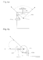
- FIG. 4a is a concept view showing a schematic construction of a driver for a panning of a camera according to an embodiment of the present invention.
- FIG. 4b is a concept view showing a schematic construction of a driver for a tilting of a camera according to an embodiment of the present invention.
- the first axis driver 310 includes a camera mounting section 401, a rotating shaft 402a, a motor (not shown), and an origin sensor 403a.
- a camera is mounted at the camera mounting portion 401.
- the camera mounting portion 401 is connected to the rotating shaft 402a and rotates.
- the rotating shaft 402a rotates the camera mounting portion 401.
- the motor drives the rotating shaft 402a.
- the origin sensor 403a senses whether or not the camera is positioned at an origin and transfers a sensed result to the control section 340.
- the robot cleaner As a power is supplied to the robot cleaner, the robot cleaner starts to operate.
- the control section 340 supplies a power to the motor, and controls the motor to position the camera at the origin. It is preferred that a stepped motor with a precision position control function is used as the motor.
- the robot cleaner travels to perform a cleaning work, and performs a panning operation for sensing obstacles according to the aforementioned program.
- the panning operation can theoretically rotate at an angle ranging from 0 to 360 degrees. However, in order to simplify a construction, be small-sized, and reduce manufacturing cost, the panning operation preferably rotates at a predetermined angle range, for example, an angle range of approximately 0 to120 degrees.
- the control section 340 controls a driver of a robot cleaner body to horizontally rotate the robot cleaner itself, thereby photographing an image of a corresponding area.
- an origin sensor 403a such as a contact sensor is provided corresponding to an origin of the camera and senses whether or not the camera is positioned at the origin.
- the origin sensor 403a senses whether or not the camera is positioned at the origin through contacting and transfers a sensed result to the control section 340.
- the camera photographs an image in a state positioned at a predetermined angle, or determines a photograph area according to a laser beam in the same manner as in prior art and photographs the image.
- the second axis driver 320 has substantially the same construction and control method as those of the first axis driver 310. The difference is that a moving direction of the second axis driver 320 differs from that of the first axis driver 310. That is, as shown in FIG. 4b, the second axis driver 320 includes a camera mounting section 401, a rotating shaft 402b, a motor (not shown), and an origin sensor 403b. A camera is mounted at the camera mounting portion 401. The camera mounting portion 401 is connected to the rotating shaft 402b and rotates. The rotating shaft 402b rotates the camera mounting portion 401. The motor drives the rotating shaft 402b. The origin sensor 403b.senses whether or not the camera is positioned at an origin and transfers a sensed result to the control section 340.
- the control section 340 supplies a power to the motor, and controls the motor to position the camera at the origin. It is preferred that a stepped motor with a precision position control function is used as the motor.
- the robot cleaner performs a tilting operation for confirming the position of the robot cleaner according to the aforementioned program.
- the tilting operation can theoretically rotate at an angle ranging from 0 to 180 degrees.
- the panning operation preferably rotates at a predetermined angle, for example, an angle ranging from approximately 0 to 90 degrees.
- the control section 340 controls a driver of a robot cleaner body to perform a rectilinear motion for the robot cleaner, namely, to forward or back a robot cleaner body, thereby photographing an image of a corresponding area.
- an origin sensor 403a such as a contact sensor is provided corresponding to an origin of the camera and senses whether or not the camera is positioned at the origin.
- the origin sensor 403a senses whether or not the camera is positioned at the origin through contacting and transfers a sensed result to the control section 340.
- the camera photographs an image in a state positioned at a predetermined angle, or determines a photograph area according to a laser beam in the same manner as in prior art and photographs the image.
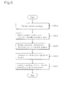
- FIG. 5 is a flow chart for illustrating a method for controlling a camera according to an embodiment of the present invention.
- the control section 340 positions the camera at an origin (step S501).
- the origin is an initial position of the camera.
- the camera can drive from the origin to the first axis direction or the second axis direction. Namely, the origin is positioned at an intersection of a first axis and a second axis.
- the control section 340 controls the first axis driver 310 or the second axis driver 320 at need during a traveling of the robot cleaner, so that it photographs front obstacles or a label installed at an upper side for compensating a position of the robot cleaner.
- the label is marked as a predetermined pattern or character and is made of a shape to be easily attached at a position such as a ceiling or a wall in order to distinguish a space to which the label is attached from other spaces.
- the control section 340 judges whether the robot cleaner is disposed at a specific position, for example, sitting room, living room, or kitchen. In a case of a wide space, the control section 340 judges whether the robot cleaner is disposed at a specific part, for example, a first zone, a second zone, or a third zone of a living room wherein the living room is divided into three zones including the first zone, the second zone, and the third zone.
- the camera photographs an image while the first axis drive 310 rotates camera in a first axis direction (step S502). Further, the camera photographs an image while the second axis driver 320 rotates the camera in a second axis direction (step S503). This causes the camera to obtain an image for sensing a presence and a shape of obstacles or confirming a position of the robot cleaner.
- the image processor 330 receives the images, and separately stored a first image photographed by the first axis driver 310 driven and a second image photographed by a second axis driver 320 driven in a memory (not shown). Further, the image processor 330 reads photographed images to either sense presence or absence and a shape of the obstacles, or identifies a specific label for confirming the position of the robot cleaner (step S504).
- control section 340 continues to travel or changes a traveling direction according to the confirmation result, or continues to control a traveling including a photograph of additional images if necessary (step S505).
- the camera photographs obstacle while the first axis drive 310 rotates camera in a horizontal direction. Further, the camera photographs a label for a position detection installed at a ceiling or a wall while the second axis driver 320 rotates the camera in a vertical direction.
- a horizontal rotation for sensing the obstacles that is, a panning operation can theoretically rotates at an angle ranging from 0 to 360 degrees.
- the panning operation preferably rotates at a predetermined angle range, for example, an angle range of approximately 0 to120 degrees.
- the control section 340 controls a driver of a robot cleaner body to horizontally rotate the robot cleaner itself, thereby photographing an image of a corresponding area.
- a vertical rotation for photographing a label installed at a ceiling or a wall namely, a tilting operation can theoretically rotates at an angle ranging from 0 to 180 degrees.
- the panning operation preferably rotates at a predetermined angle, for example, an angle ranging from approximately 0 to 90 degrees.
- the control section 340 controls a driver of a robot cleaner body to perform a rectilinear motion for the robot cleaner, namely, to forward or back a robot cleaner body, thereby photographing an image of a corresponding area.
- the robot clean alternately or repeatedly needs to perform a first work of sensing the obstacles and a second work of detecting and compensation a position.
- the control section 340 moves the camera to an origin and then controls a drive of another axis to change the work.
- the control section 340 controls the first axis driver 310 to sense the obstacles, so as to change the first work to the second work of detecting a position
- the control section 340 controls the first axis driver 310 to position the camera at the origin and then controls the second axis driver 320 to move the camera in a vertical direction
- the camera photographs an image.
- the control section 340 may alternately control the first axis driver 310 and the second axis driver 320 according to a predetermined program.
- the predetermined program is set by at least on basis and is stored in a memory area (not shown) of the robot cleaner, so that the control section 340 may access the program.
- a program set based on the time repeats a first work of sensing the obstacles and the second work of detecting a position according to a predetermined time interval. For example, after driving, the program alternately repeats the first work of sensing the obstacles and the second work of detecting the position at one minute interval. Otherwise, the program can repeat a pattern in such a manner that the first work of sensing the obstacles is performed three times and the second work of detecting a position once.
- the predetermined program can be prepared based on specific conditions or moving distance. After the robot cleaner moved by a predetermined distance, for example, 2m every time, a first work of sensing the obstacles and the second work of detecting the position are alternately performed. Otherwise, when obstacles approach within 1 m, the second work of detecting the position is carried out.
- the predetermined program can be prepared using a pattern based on the time, moving distance, or specific conditions, or simultaneously applying them according to a priority order under a control of the control section 340.
- the present invention can provide a robot cleaner of a simple construction, which photograph an ambient image by moving the one camera in two different axis directions wherein an image obtained by moving one shaft is for sensing obstacles, and an image by moving another shaft is for confirming and compensating a position of the robot cleaner.
- the prevent invention may provide an apparatus and a method for controlling a camera of a robot cleaner, which may sense objects present at different directions by rotating one camera in horizontal and vertical directions.
- one camera of the robot cleaner repeats to sense obstacles and confirm a position thereof. This causes the robot cleaner to effectively travel and clean entire cleaning zones.
Abstract
Description
- This application claims benefit under 35 U.S.C. § 119 from
Korean Patent Application No. 2005-0101804, filed on October 27, 2005 - The present invention relates to an apparatus and a method for controlling a camera mounted at a robot cleaner in order to sense obstacles and perform a position compensation, and more particularly, to an apparatus and a method for controlling a camera of a robot cleaner, which photograph a subject to sense obstacles and to photograph a label for a position compensation by moving and controlling one camera mounted at a robot cleaner in two axis directions.
- A conventional robot cleaner may sense cleaning zones or obstacles using a camera.
Korean patent application No. 1998-23269 Korean patent application No. 2000-68446 - On the other hand, a technique confirming a position of a robot cleaner using a camera while the robot cleaner cleans while moving to a predetermined zone is known. FIG. 1 is a perspective view for schematically showing a conventional robot cleaner with a camera for position compensation. A
front camera 110 is installed in front of the robot cleaner. Thefront camera 110 senses whether or not there are obstacles. That is, thefront camera 110 photographs a front of the robot cleaner to sense obstacles. On the other hand, anupper camera 120 confirms or compensates a position of the robot cleaner. More particularly, theupper camera 120 photographs a predetermined label installed at a ceiling or a wall of an indoor, and confirms or estimates the position of the robot cleaner based on the photographed label. - However, the conventional robot cleaner should separately include a camera for sensing obstacles and a camera for confirming a position thereof. That will make a construction of the robot cleaner complicated. Further, a use of a plurality of camera modules boosts manufacturing cost of the robot cleaner.
- Accordingly, it is an object of the present invention to provide an apparatus and a method for controlling a camera of a robot cleaner, which embody a function of sensing obstacles and a function of confirming and compensating a position of a robot cleaner with one camera mounted at the robot cleaner by moving the one camera in two different axis directions to photograph an image.
- Another object of the present invention is to provide an apparatus and a method for controlling a camera of a robot cleaner, which may sense objects existing at different directions by rotating the camera in horizontal and vertical directions.
- A further object of the present invention is to provide an apparatus and a method for controlling a camera of a robot cleaner, which may effectively travel the robot cleaner by repeating a photograph operation for sensing obstacles and confirming a position of the robot cleaner using one camera while the robot cleaner cleans a predetermined zone.
- The above object of the present invention is substantially realized by providing a n apparatus for controlling a camera of a robot cleaner comprising: a
first axis driver 310 for driving a camera mounted at the robot cleaner in a first axis direction; asecond axis driver 320 for driving the camera in a second axis direction other than the first axis direction; animage processor 330 for receiving and processing an image photographed by the camera; and acontrol section 340 for controlling the first axis driver and the second axis driver, and controlling a traveling of the robot cleaner based on the image photographed by the camera. - In accordance with another aspect of the present invention, there is provided a method for controlling a camera of a robot cleaner, comprising the steps of: (i) initializing a camera mounted at the robot cleaner with an origin; (ii) driving the camera in a first axis direction and photographing a first image by the camera; (iii) driving the camera in a second axis direction other than the first axis direction and photographing a second image by the camera; (iv) receiving and processing the first and second images photographed by the camera; (v) controlling a traveling of the robot cleaner based on the first and second photographed images.
- In accordance with the aforementioned arrangements, by moving one camera mounted at the robot cleaner in two different axis directions and performing photographing operation using the one camera, a function of sensing obstacles and a function of detecting and compensating a position of the robot cleaner can be simultaneously embodied.
- The above aspects and features of the present invention will be more apparent by describing certain embodiments of the present invention with reference to the accompanying drawings, in which:
- FIG. 1 is a perspective view for schematically showing a conventional robot cleaner with a camera;
- FIG. 2 is a concept view showing an operation principle of a camera mounted at a robot cleaner according to an embodiment of the present invention;
- FIG. 3 is a block diagram showing a schematic construction of the robot cleaner according to an embodiment of the present invention;
- FIG. 4a is a concept view showing a schematic construction of a driver for a panning of a camera according to an embodiment of the present invention;
- FIG. 4b is a concept view showing a schematic construction of a driver for a tilting of a camera according to an embodiment of the present invention; and
- FIG. 5 is a flow chart for illustrating a method for controlling a camera according to an embodiment of the present invention.
- Hereinafter, preferable embodiments according to the present invention will be described with reference to the accompanying drawings. Here, when one element is connected to another element, one element may be not only directly connected to another element but also indirectly connected to another element via another element. Further, irrelative elements are omitted for clarity.
- FIG. 2 is a concept view showing an operation principle of a camera mounted at a robot cleaner according to an embodiment of the present invention.
- As shown in FIG. 2, a camera module mounted at the robot cleaner rotates up and down, and from side to side, to detect or avoid obstacles existing at a front direction or to detect a label installed at a ceiling or a wall in order to recognize a position of the robot cleaner. So as to do this, the camera is installed at a front upper side of the robot cleaner. The camera performs a tilting operation rotating up and down and a panning operation rotating from side to side, to photograph a subject.
- The photographed images are divided and stored according to whether the images are for sensing obstacles or for detecting a label. When it is judged through an image processing that the photographed images are for sensing obstacles, the camera detects presence or absence, distance, and pattern of the obstacles. Because a technique for detecting presence or absence, distance, and pattern of the obstacles using photographed images is well known, a detailed description thereof is omitted.
- On the other hand, when the photographed images are for detecting the label, the camera detects whether or not there is a corresponding label, or the label is a specific one among various kinds of labels, for example, a label indicating living room, kitchen, sitting room, or a first zone or a second zone of the living room. Because this procedure is achieved by a known image processing, a detailed explanation thereof is omitted.
- FIG. 3 is a block diagram showing a schematic construction of the robot cleaner according to an embodiment of the present invention.
- A
first axis driver 310 rotates and moves a camera in a first axis direction. Asecond axis driver 320 rotates and moves the same camera in a second axis direction. - An
image processor 330 separately stores a first image photographed by the camera driven by thefirst axis driver 310 and a second image photographed by the camera driven by thesecond axis driver 320 in a memory (not shown). Theimage processor 330 reads the photographed images to sense a presence or absence and a pattern of obstacles and to detect a specific label for confirming a position of the robot cleaner. - As a power is applied to the robot cleaner, it operates. When the robot cleaner operates, a
control section 340 positions the camera at an origin. Here, the origin is an initial position of the camera. The camera can drive from the origin to the first axis direction or the second axis direction. Namely, the origin is positioned at an intersection of a first axis and a second axis. Once the camera is positioned at the origin, thecontrol section 340 controls thefirst axis driver 310 or thesecond axis driver 320 at need during a traveling of the robot cleaner, so that it photographs front obstacles or a label installed at an upper side for compensating a position of the robot cleaner. The label is marked as a predetermined pattern or character and is made of a shape to be easily attached at a position such as a ceiling or a wall in order to distinguish a space to which the label is attached from other spaces. When a specific label is detected, thecontrol section 340 judges whether the robot cleaner is disposed at a specific position, for example, sitting room, living room, or kitchen. In a case of a wide space, thecontrol section 340 judges whether the robot cleaner is disposed at a specific part, for example, a first zone, a second zone, or a third zone of a living room wherein the living room is divided into three zones including the first zone, the second zone, and the third zone. - Preferably, it may be structured that the camera photographs obstacle while the first axis drive 310 rotates camera in a horizontal direction. Further, the camera photographs a label for a position detection installed at a ceiling or a wall while the
second axis driver 320 rotates the camera in a vertical direction. - On the other hand, the robot clean alternately or repeatedly needs to perform a first work of sensing the obstacles and a second work of detecting and compensation a position. In order to change the first work of sensing the obstacles to the second work of detecting and compensation a position, namely, to change one work to another work, the
control section 340 moves the camera to an origin and then controls a drive of another axis to change the work. For example, when thecontrol section 340 controls thefirst axis driver 310 to sense the obstacles, so as to change the first work to the second work of detecting a position, while thecontrol section 340 controls thefirst axis driver 310 to position the camera at the origin and then controls thesecond axis driver 320 to move the camera in a vertical direction, the camera photographs an image. - Furthermore, when the robot cleaner cleans a wide zone in which a plurality of obstacles are present, the first work of sensing the obstacles and the second work of detecting a position generally repeat. In this case, the
control section 340 may alternately control thefirst axis driver 310 and thesecond axis driver 320 according to a predetermined program. The predetermined program is set by at least on basis and is stored in a memory area (not shown) of the robot cleaner, so that thecontrol section 340 may access the program. - First, a program set based on the time repeats a first work of sensing the obstacles and the second work of detecting a position according to a predetermined time interval. For example, after driving, the program alternately repeats the first work of sensing the obstacles and the second work of detecting the position at one-minute intervals. Otherwise, the program can repeat a pattern in such a manner that the first work of sensing the obstacles is performed three times and the second work of detecting a position once.
- On the other hand, the predetermined program can be prepared based on specific conditions or moving distance. After the robot cleaner moved by a predetermined distance, for example, 2m every time, a first work of sensing the obstacles and the second work of detecting the position are alternately performed. Otherwise, when obstacles approach within 1 m, the second work of detecting the position is carried out.
- As is seen from the forgoing description, the predetermined program can be prepared using a pattern based on the time, moving distance, or specific conditions, or simultaneously applying them according to a priority order under a control of the
control section 340. - FIG. 4a is a concept view showing a schematic construction of a driver for a panning of a camera according to an embodiment of the present invention. FIG. 4b is a concept view showing a schematic construction of a driver for a tilting of a camera according to an embodiment of the present invention.
- The
first axis driver 310 includes acamera mounting section 401, arotating shaft 402a, a motor (not shown), and anorigin sensor 403a. A camera is mounted at thecamera mounting portion 401. Thecamera mounting portion 401 is connected to therotating shaft 402a and rotates. Therotating shaft 402a rotates thecamera mounting portion 401. The motor drives therotating shaft 402a. The origin sensor 403a.senses whether or not the camera is positioned at an origin and transfers a sensed result to thecontrol section 340. - As a power is supplied to the robot cleaner, the robot cleaner starts to operate. When the robot cleaner starts to operate, the
control section 340 supplies a power to the motor, and controls the motor to position the camera at the origin. It is preferred that a stepped motor with a precision position control function is used as the motor. The robot cleaner travels to perform a cleaning work, and performs a panning operation for sensing obstacles according to the aforementioned program. The panning operation can theoretically rotate at an angle ranging from 0 to 360 degrees. However, in order to simplify a construction, be small-sized, and reduce manufacturing cost, the panning operation preferably rotates at a predetermined angle range, for example, an angle range of approximately 0 to120 degrees. In order to photograph an image of an area being not included in the predetermined angle, thecontrol section 340 controls a driver of a robot cleaner body to horizontally rotate the robot cleaner itself, thereby photographing an image of a corresponding area. - On the other hand, an
origin sensor 403a such as a contact sensor is provided corresponding to an origin of the camera and senses whether or not the camera is positioned at the origin. When the camera is positioned at the origin, theorigin sensor 403a senses whether or not the camera is positioned at the origin through contacting and transfers a sensed result to thecontrol section 340. - The camera photographs an image in a state positioned at a predetermined angle, or determines a photograph area according to a laser beam in the same manner as in prior art and photographs the image.
- The
second axis driver 320 has substantially the same construction and control method as those of thefirst axis driver 310. The difference is that a moving direction of thesecond axis driver 320 differs from that of thefirst axis driver 310. That is, as shown in FIG. 4b, thesecond axis driver 320 includes acamera mounting section 401, arotating shaft 402b, a motor (not shown), and anorigin sensor 403b. A camera is mounted at thecamera mounting portion 401. Thecamera mounting portion 401 is connected to therotating shaft 402b and rotates. Therotating shaft 402b rotates thecamera mounting portion 401. The motor drives therotating shaft 402b. The origin sensor 403b.senses whether or not the camera is positioned at an origin and transfers a sensed result to thecontrol section 340. - When a power is supplied to the robot cleaner, or a work for sensing obstacles changes to a work of confirming the position, the
control section 340 supplies a power to the motor, and controls the motor to position the camera at the origin. It is preferred that a stepped motor with a precision position control function is used as the motor. - The robot cleaner performs a tilting operation for confirming the position of the robot cleaner according to the aforementioned program. The tilting operation can theoretically rotate at an angle ranging from 0 to 180 degrees. However, in order to simplify a construction, be small-sized, and reduce manufacturing cost, the panning operation preferably rotates at a predetermined angle, for example, an angle ranging from approximately 0 to 90 degrees. In order to photograph an image of an area being not included in the predetermined angle, the
control section 340 controls a driver of a robot cleaner body to perform a rectilinear motion for the robot cleaner, namely, to forward or back a robot cleaner body, thereby photographing an image of a corresponding area. - On the other hand, an
origin sensor 403a such as a contact sensor is provided corresponding to an origin of the camera and senses whether or not the camera is positioned at the origin. When the camera is positioned at the origin, theorigin sensor 403a senses whether or not the camera is positioned at the origin through contacting and transfers a sensed result to thecontrol section 340. The camera photographs an image in a state positioned at a predetermined angle, or determines a photograph area according to a laser beam in the same manner as in prior art and photographs the image. - FIG. 5 is a flow chart for illustrating a method for controlling a camera according to an embodiment of the present invention.
- As shown in FIG. 5, when a power is applied to drive the robot cleaner, the
control section 340 positions the camera at an origin (step S501). Here, the origin is an initial position of the camera. The camera can drive from the origin to the first axis direction or the second axis direction. Namely, the origin is positioned at an intersection of a first axis and a second axis. Once the camera is positioned at the origin, thecontrol section 340 controls thefirst axis driver 310 or thesecond axis driver 320 at need during a traveling of the robot cleaner, so that it photographs front obstacles or a label installed at an upper side for compensating a position of the robot cleaner. - The label is marked as a predetermined pattern or character and is made of a shape to be easily attached at a position such as a ceiling or a wall in order to distinguish a space to which the label is attached from other spaces. When a specific label is detected, the
control section 340 judges whether the robot cleaner is disposed at a specific position, for example, sitting room, living room, or kitchen. In a case of a wide space, thecontrol section 340 judges whether the robot cleaner is disposed at a specific part, for example, a first zone, a second zone, or a third zone of a living room wherein the living room is divided into three zones including the first zone, the second zone, and the third zone. - Next, the camera photographs an image while the
first axis drive 310 rotates camera in a first axis direction (step S502). Further, the camera photographs an image while thesecond axis driver 320 rotates the camera in a second axis direction (step S503). This causes the camera to obtain an image for sensing a presence and a shape of obstacles or confirming a position of the robot cleaner. - As described earlier, when a necessary image is photographed, the
image processor 330 receives the images, and separately stored a first image photographed by thefirst axis driver 310 driven and a second image photographed by asecond axis driver 320 driven in a memory (not shown). Further, theimage processor 330 reads photographed images to either sense presence or absence and a shape of the obstacles, or identifies a specific label for confirming the position of the robot cleaner (step S504). - When the presence and the shape of the obstacles, or the position of the robot cleaner is confirmed, the
control section 340 continues to travel or changes a traveling direction according to the confirmation result, or continues to control a traveling including a photograph of additional images if necessary (step S505). - Preferably, it can be constructed that the camera photographs obstacle while the
first axis drive 310 rotates camera in a horizontal direction. Further, the camera photographs a label for a position detection installed at a ceiling or a wall while thesecond axis driver 320 rotates the camera in a vertical direction. - A horizontal rotation for sensing the obstacles, that is, a panning operation can theoretically rotates at an angle ranging from 0 to 360 degrees. However, in order to simplify a construction, be small-sized, and reduce manufacturing cost, the panning operation preferably rotates at a predetermined angle range, for example, an angle range of approximately 0 to120 degrees. In order to photograph an image of an area being not included in the predetermined angle, the
control section 340 controls a driver of a robot cleaner body to horizontally rotate the robot cleaner itself, thereby photographing an image of a corresponding area. - A vertical rotation for photographing a label installed at a ceiling or a wall, namely, a tilting operation can theoretically rotates at an angle ranging from 0 to 180 degrees. However, in order to simplify a construction, be small-sized, and reduce manufacturing cost, the panning operation preferably rotates at a predetermined angle, for example, an angle ranging from approximately 0 to 90 degrees. In order to photograph an image of an area being not included in the predetermined angle, the
control section 340 controls a driver of a robot cleaner body to perform a rectilinear motion for the robot cleaner, namely, to forward or back a robot cleaner body, thereby photographing an image of a corresponding area. - On the other hand, the robot clean alternately or repeatedly needs to perform a first work of sensing the obstacles and a second work of detecting and compensation a position. In order to change the first work of sensing the obstacles to the second work of detecting and compensation a position, namely, to change one work to another work, the
control section 340 moves the camera to an origin and then controls a drive of another axis to change the work. For example, when thecontrol section 340 controls thefirst axis driver 310 to sense the obstacles, so as to change the first work to the second work of detecting a position, while thecontrol section 340 controls thefirst axis driver 310 to position the camera at the origin and then controls thesecond axis driver 320 to move the camera in a vertical direction, the camera photographs an image. - Furthermore, when the robot cleaner cleans a wide zone in which a plurality of obstacles are present, the first work of sensing the obstacles and the second work of detecting a position generally repeat. In this case, the
control section 340 may alternately control thefirst axis driver 310 and thesecond axis driver 320 according to a predetermined program. The predetermined program is set by at least on basis and is stored in a memory area (not shown) of the robot cleaner, so that thecontrol section 340 may access the program. - First, a program set based on the time repeats a first work of sensing the obstacles and the second work of detecting a position according to a predetermined time interval. For example, after driving, the program alternately repeats the first work of sensing the obstacles and the second work of detecting the position at one minute interval. Otherwise, the program can repeat a pattern in such a manner that the first work of sensing the obstacles is performed three times and the second work of detecting a position once.
- Thereafter, the predetermined program can be prepared based on specific conditions or moving distance. After the robot cleaner moved by a predetermined distance, for example, 2m every time, a first work of sensing the obstacles and the second work of detecting the position are alternately performed. Otherwise, when obstacles approach within 1 m, the second work of detecting the position is carried out.
- As is seen from the forgoing description, the predetermined program can be prepared using a pattern based on the time, moving distance, or specific conditions, or simultaneously applying them according to a priority order under a control of the
control section 340. - By the aforementioned arrangement, the present invention can provide a robot cleaner of a simple construction, which photograph an ambient image by moving the one camera in two different axis directions wherein an image obtained by moving one shaft is for sensing obstacles, and an image by moving another shaft is for confirming and compensating a position of the robot cleaner.
- Furthermore, the prevent invention may provide an apparatus and a method for controlling a camera of a robot cleaner, which may sense objects present at different directions by rotating one camera in horizontal and vertical directions.
- In addition, as mentioned above, while the robot cleaner cleans a predetermine zone, one camera of the robot cleaner repeats to sense obstacles and confirm a position thereof. This causes the robot cleaner to effectively travel and clean entire cleaning zones.
- The foregoing embodiment and advantages are merely exemplary and are not to be construed as limiting the present invention. The present teaching can be readily applied to other types of apparatuses. Also, the description of the embodiments of the present invention is intended to be illustrative, and not to limit the scope of the claims, and many alternatives, modifications, and variations will be apparent to those skilled in the art.
Claims (13)
- An apparatus for controlling a camera of a robot cleaner comprising:a first axis driver for driving a camera mounted at the robot cleaner in a first axis direction;a second axis driver for driving the camera in a second axis direction other than the first axis direction;an image processor for receiving and processing an image photographed by the camera; anda control section for controlling the first axis driver and the second axis driver, and controlling a traveling of the robot cleaner based on the image photographed by the camera.
- The apparatus as claimed in claim 1, wherein the first axis driver rotates the camera in a horizontal direction, and the second axis driver rotates the camera in a vertical direction.
- The apparatus as claimed in claim 2, wherein the control section controls a driver of a robot cleaner body to horizontally rotate the robot cleaner itself in order to photograph an image of a region beyond the range of 120°.
- The apparatus as claimed in claim 2, wherein the control section controls a driver of a robot cleaner body to perform a rectilinear motion for the robot cleaner itself in order to photograph an image of a region beyond the range of 90°.
- The apparatus as claimed in any of claims 1 to 4, wherein the control section alternately drives the first axis driver and the second axis driver according to a predetermined pattern.
- The apparatus as claimed in claim 5, wherein the predetermined pattern is determined based on time, a moving distance of the robot cleaner, or a combination thereof.
- The apparatus as claimed in any of claims 1 to 6, wherein a first image photographed by the camera driven in the first axis direction is obstacle information, and a second image photographed by the camera driven in the second axis direction is position information of the robot cleaner.
- The apparatus as claimed in any of claims 1 to 7, wherein each of the first and second axis drivers includes an origin sensor for confirming whether the camera is positioned at an origin.
- A method for controlling a camera of a robot cleaner, comprising the steps of:(i) initializing a camera mounted at the robot cleaner with an origin;(ii) driving the camera in a first axis direction and photographing a first image by the camera;(iii) driving the camera in a second axis direction other than the first axis direction and photographing a second image by the camera;(iv) receiving and processing the first and second images photographed by the camera;(v) controlling a traveling of the robot cleaner based on the first and second photographed images.
- The method as claimed in claim 9, wherein step (ii) rotates the camera in a horizontal direction within a first predetermined angle range, and
step (iii) rotates the camera in a vertical direction within a second predetermined angle range. - The method as claimed in claim 10, wherein a first image photographed by step (ii) is obstacle information, and a second image photographed by step (iii) is position information of the robot cleaner.
- The method as claimed in claim 10 or 11, wherein steps (ii) and (iii) repeat according a predetermined pattern.
- The method as claimed in claim 12, wherein the predetermined pattern is determined based on time, a moving distance of the robot cleaner, or a combination thereof.
Applications Claiming Priority (1)
| Application Number | Priority Date | Filing Date | Title |
|---|---|---|---|
| KR1020050101804A KR100738888B1 (en) | 2005-10-27 | 2005-10-27 | The Apparatus and Method for Controlling the Camera of Robot Cleaner |
Publications (3)
| Publication Number | Publication Date |
|---|---|
| EP1783573A2 true EP1783573A2 (en) | 2007-05-09 |
| EP1783573A3 EP1783573A3 (en) | 2009-06-24 |
| EP1783573B1 EP1783573B1 (en) | 2013-01-02 |
Family
ID=37744547
Family Applications (1)
| Application Number | Title | Priority Date | Filing Date |
|---|---|---|---|
| EP06122977A Expired - Fee Related EP1783573B1 (en) | 2005-10-27 | 2006-10-26 | Apparatus and method for controlling camera of robot cleaner |
Country Status (4)
| Country | Link |
|---|---|
| US (1) | US7711450B2 (en) |
| EP (1) | EP1783573B1 (en) |
| KR (1) | KR100738888B1 (en) |
| CN (1) | CN100590520C (en) |
Cited By (1)
| Publication number | Priority date | Publication date | Assignee | Title |
|---|---|---|---|---|
| AT15526U1 (en) * | 2016-06-07 | 2017-11-15 | Tridonic Gmbh & Co Kg | Sensor arrangement for the optimized navigation of a cleaning robot |
Families Citing this family (56)
| Publication number | Priority date | Publication date | Assignee | Title |
|---|---|---|---|---|
| KR100818740B1 (en) * | 2006-10-13 | 2008-04-01 | 엘지전자 주식회사 | Robot cleaner and method for controlling the same |
| JP4837116B2 (en) * | 2010-03-05 | 2011-12-14 | ファナック株式会社 | Robot system with visual sensor |
| US8725443B2 (en) | 2011-01-24 | 2014-05-13 | Microsoft Corporation | Latency measurement |
| US8988087B2 (en) | 2011-01-24 | 2015-03-24 | Microsoft Technology Licensing, Llc | Touchscreen testing |
| US8982061B2 (en) | 2011-02-12 | 2015-03-17 | Microsoft Technology Licensing, Llc | Angular contact geometry |
| US9542092B2 (en) | 2011-02-12 | 2017-01-10 | Microsoft Technology Licensing, Llc | Prediction-based touch contact tracking |
| US8773377B2 (en) | 2011-03-04 | 2014-07-08 | Microsoft Corporation | Multi-pass touch contact tracking |
| US8913019B2 (en) | 2011-07-14 | 2014-12-16 | Microsoft Corporation | Multi-finger detection and component resolution |
| US9378389B2 (en) | 2011-09-09 | 2016-06-28 | Microsoft Technology Licensing, Llc | Shared item account selection |
| US9785281B2 (en) | 2011-11-09 | 2017-10-10 | Microsoft Technology Licensing, Llc. | Acoustic touch sensitive testing |
| US8914254B2 (en) | 2012-01-31 | 2014-12-16 | Microsoft Corporation | Latency measurement |
| KR102142162B1 (en) | 2012-08-27 | 2020-09-14 | 에이비 엘렉트로룩스 | Robot positioning system |
| US9317147B2 (en) | 2012-10-24 | 2016-04-19 | Microsoft Technology Licensing, Llc. | Input testing tool |
| FR3001298B1 (en) * | 2013-01-18 | 2016-05-27 | Archos | METHOD AND SYSTEM FOR PROVIDING A MOBILE DEVICE WITH INFORMATION ON ITS POSITION IN RELATION TO A TARGET, ROBOT INCORPORATING SUCH A SYSTEM AND TABLET |
| KR101490170B1 (en) * | 2013-03-05 | 2015-02-05 | 엘지전자 주식회사 | Robot cleaner |
| KR101450537B1 (en) * | 2013-03-05 | 2014-10-14 | 엘지전자 주식회사 | Robot cleaner |
| KR101450569B1 (en) * | 2013-03-05 | 2014-10-14 | 엘지전자 주식회사 | Robot cleaner |
| KR101395888B1 (en) | 2013-03-21 | 2014-05-27 | 엘지전자 주식회사 | Robot cleaner and operating method |
| JP2014200449A (en) * | 2013-04-04 | 2014-10-27 | シャープ株式会社 | Self-propelled vacuum cleaner |
| CN105101855A (en) | 2013-04-15 | 2015-11-25 | 伊莱克斯公司 | Robotic vacuum cleaner with protruding sidebrush |
| WO2014169943A1 (en) | 2013-04-15 | 2014-10-23 | Aktiebolaget Electrolux | Robotic vacuum cleaner |
| WO2015008874A1 (en) * | 2013-07-15 | 2015-01-22 | 엘지전자 주식회사 | Robot cleaner and method for auto-correcting 3d sensor of the robot cleaner |
| KR102099495B1 (en) | 2013-12-19 | 2020-04-09 | 에이비 엘렉트로룩스 | Sensing climb of obstacle of a robotic cleaning device |
| WO2015090397A1 (en) | 2013-12-19 | 2015-06-25 | Aktiebolaget Electrolux | Robotic cleaning device |
| EP3082537B1 (en) | 2013-12-19 | 2020-11-18 | Aktiebolaget Electrolux | Robotic cleaning device and method for landmark recognition |
| KR102393550B1 (en) | 2013-12-19 | 2022-05-04 | 에이비 엘렉트로룩스 | Prioritizing cleaning areas |
| KR102124235B1 (en) | 2013-12-19 | 2020-06-24 | 에이비 엘렉트로룩스 | Robotic cleaning device with perimeter recording function |
| CN105744872B (en) | 2013-12-19 | 2020-01-14 | 伊莱克斯公司 | Adaptive speed control of rotating side brushes |
| EP3082544B1 (en) | 2013-12-19 | 2020-10-07 | Aktiebolaget Electrolux | Robotic vacuum cleaner with side brush moving in spiral pattern |
| EP3082539B1 (en) | 2013-12-20 | 2019-02-20 | Aktiebolaget Electrolux | Dust container |
| EP3167341B1 (en) | 2014-07-10 | 2018-05-09 | Aktiebolaget Electrolux | Method for detecting a measurement error in a robotic cleaning device |
| CN104407610A (en) * | 2014-07-21 | 2015-03-11 | 东莞市万锦电子科技有限公司 | Ground cleaning robot system and control method thereof |
| JP6459098B2 (en) | 2014-09-08 | 2019-01-30 | アクチエボラゲット エレクトロルックス | Robot vacuum cleaner |
| WO2016037635A1 (en) | 2014-09-08 | 2016-03-17 | Aktiebolaget Electrolux | Robotic vacuum cleaner |
| JP6331971B2 (en) * | 2014-10-30 | 2018-05-30 | 三菱電機株式会社 | Self-propelled vacuum cleaner |
| EP3230814B1 (en) | 2014-12-10 | 2021-02-17 | Aktiebolaget Electrolux | Using laser sensor for floor type detection |
| WO2016091320A1 (en) | 2014-12-12 | 2016-06-16 | Aktiebolaget Electrolux | Side brush and robotic cleaner |
| EP3234713B1 (en) | 2014-12-16 | 2022-06-15 | Aktiebolaget Electrolux | Cleaning method for a robotic cleaning device |
| EP3234714B1 (en) | 2014-12-16 | 2021-05-12 | Aktiebolaget Electrolux | Experience-based roadmap for a robotic cleaning device |
| CN107405034B (en) | 2015-04-17 | 2022-09-13 | 伊莱克斯公司 | Robot cleaning apparatus and method of controlling the same |
| CN107920709A (en) | 2015-09-03 | 2018-04-17 | 伊莱克斯公司 | Robotic cleaning device system |
| KR101897775B1 (en) * | 2016-03-04 | 2018-09-12 | 엘지전자 주식회사 | Moving robot and controlling method thereof |
| JP7035300B2 (en) | 2016-03-15 | 2022-03-15 | アクチエボラゲット エレクトロルックス | Robot Cleaning Devices, Methods for Performing Escarpment Detection in Robot Cleaning Devices, Computer Programs, and Computer Program Products |
| WO2017173553A1 (en) | 2016-04-08 | 2017-10-12 | A&K Robotics Inc. | Autoscrubber convertible between manual and autonomous operation |
| EP3454707B1 (en) | 2016-05-11 | 2020-07-08 | Aktiebolaget Electrolux | Robotic cleaning device |
| JP6814095B2 (en) * | 2017-05-23 | 2021-01-13 | 東芝ライフスタイル株式会社 | Vacuum cleaner |
| KR20220025250A (en) | 2017-06-02 | 2022-03-03 | 에이비 엘렉트로룩스 | Method of detecting a difference in level of a surface in front of a robotic cleaning device |
| KR101999959B1 (en) * | 2017-06-26 | 2019-07-15 | 엘지전자 주식회사 | Robot cleaner |
| JP6989210B2 (en) | 2017-09-26 | 2022-01-05 | アクチエボラゲット エレクトロルックス | Controlling the movement of robot cleaning devices |
| US11122950B2 (en) * | 2018-03-30 | 2021-09-21 | Midea Robozone Technology Co., Ltd. | Cleaning robot and cleaning robot system |
| KR102201002B1 (en) * | 2019-03-26 | 2021-01-12 | 엘지전자 주식회사 | Robot cleaner |
| CN110151073A (en) * | 2019-06-20 | 2019-08-23 | 小狗电器互联网科技(北京)股份有限公司 | The photographic device of sweeper |
| KR102225909B1 (en) * | 2019-08-14 | 2021-03-11 | 엘지전자 주식회사 | A robot equipped with cleaning functions for camera vision and its control method |
| CN112770034B (en) * | 2020-03-06 | 2022-05-06 | 甘肃新视能科技有限公司 | High-speed monitoring equipment |
| CN114680732A (en) * | 2020-12-25 | 2022-07-01 | 苏州宝时得电动工具有限公司 | Cleaning robot and cleaning control method thereof |
| DE102021206645B4 (en) | 2021-06-28 | 2023-04-27 | BSH Hausgeräte GmbH | Mobile floor cleaning device and method for operating the same |
Citations (5)
| Publication number | Priority date | Publication date | Assignee | Title |
|---|---|---|---|---|
| US4855822A (en) * | 1988-01-26 | 1989-08-08 | Honeywell, Inc. | Human engineered remote driving system |
| KR20000002483A (en) * | 1998-06-20 | 2000-01-15 | 배길성 | Recognizing device of cleaning zone form for robot cleaner and method thereof |
| KR20020038296A (en) * | 2000-11-17 | 2002-05-23 | 이충전 | Apparatus for detecting obstacle in mobile robot and method for detecting the same |
| US20020153184A1 (en) * | 2001-04-18 | 2002-10-24 | Jeong-Gon Song | Robot cleaner, robot cleaning system and method for controlling same |
| US20020153185A1 (en) * | 2001-04-18 | 2002-10-24 | Jeong-Gon Song | Robot cleaner, system employing the same and method for re-connecting to external recharging device |
Family Cites Families (11)
| Publication number | Priority date | Publication date | Assignee | Title |
|---|---|---|---|---|
| KR100335967B1 (en) | 1999-07-09 | 2002-05-09 | 김운용 | Pan/tilt camera |
| JP3489510B2 (en) * | 1999-11-02 | 2004-01-19 | 日本電気株式会社 | Camera system and display device |
| US6496754B2 (en) * | 2000-11-17 | 2002-12-17 | Samsung Kwangju Electronics Co., Ltd. | Mobile robot and course adjusting method thereof |
| US6604868B2 (en) * | 2001-06-04 | 2003-08-12 | Kent Hsieh | Microprocessor-controlled servo device for carrying and moving camera |
| JP2003131311A (en) * | 2001-10-22 | 2003-05-09 | Elmo Co Ltd | Pan and tilt camera device |
| JP4301493B2 (en) * | 2003-04-09 | 2009-07-22 | カシオ計算機株式会社 | Imaging device |
| US20050035991A1 (en) * | 2003-08-12 | 2005-02-17 | Fredrickson Daniel John | Inkjet printer cleaning system and method |
| US20050222710A1 (en) * | 2004-04-06 | 2005-10-06 | Schell Steven E | Mechanical arrangement and components for reducing error in deduced reckoning |
| JP2006119164A (en) * | 2004-10-19 | 2006-05-11 | Konica Minolta Opto Inc | Imaging optical system |
| US20060115263A1 (en) * | 2004-11-29 | 2006-06-01 | Eastman Kodak Company | Device and method for unloading film |
| EP2769387A4 (en) | 2011-10-17 | 2015-12-23 | Guitammer Company | Vibration transducer and actuator |
-
2005
- 2005-10-27 KR KR1020050101804A patent/KR100738888B1/en active IP Right Grant
-
2006
- 2006-10-26 EP EP06122977A patent/EP1783573B1/en not_active Expired - Fee Related
- 2006-10-26 US US11/553,289 patent/US7711450B2/en active Active
- 2006-10-27 CN CN200610142895A patent/CN100590520C/en not_active Expired - Fee Related
Patent Citations (5)
| Publication number | Priority date | Publication date | Assignee | Title |
|---|---|---|---|---|
| US4855822A (en) * | 1988-01-26 | 1989-08-08 | Honeywell, Inc. | Human engineered remote driving system |
| KR20000002483A (en) * | 1998-06-20 | 2000-01-15 | 배길성 | Recognizing device of cleaning zone form for robot cleaner and method thereof |
| KR20020038296A (en) * | 2000-11-17 | 2002-05-23 | 이충전 | Apparatus for detecting obstacle in mobile robot and method for detecting the same |
| US20020153184A1 (en) * | 2001-04-18 | 2002-10-24 | Jeong-Gon Song | Robot cleaner, robot cleaning system and method for controlling same |
| US20020153185A1 (en) * | 2001-04-18 | 2002-10-24 | Jeong-Gon Song | Robot cleaner, system employing the same and method for re-connecting to external recharging device |
Cited By (1)
| Publication number | Priority date | Publication date | Assignee | Title |
|---|---|---|---|---|
| AT15526U1 (en) * | 2016-06-07 | 2017-11-15 | Tridonic Gmbh & Co Kg | Sensor arrangement for the optimized navigation of a cleaning robot |
Also Published As
| Publication number | Publication date |
|---|---|
| US7711450B2 (en) | 2010-05-04 |
| CN1955839A (en) | 2007-05-02 |
| US20070100501A1 (en) | 2007-05-03 |
| EP1783573A3 (en) | 2009-06-24 |
| EP1783573B1 (en) | 2013-01-02 |
| KR20070045475A (en) | 2007-05-02 |
| CN100590520C (en) | 2010-02-17 |
| KR100738888B1 (en) | 2007-07-12 |
Similar Documents
| Publication | Publication Date | Title |
|---|---|---|
| EP1783573B1 (en) | Apparatus and method for controlling camera of robot cleaner | |
| EP3696641B1 (en) | Robot cleaner and method of controlling the same | |
| EP1977673B1 (en) | Wall-following robot cleaner and method to control the same | |
| US7660650B2 (en) | Self-propelled working robot having horizontally movable work assembly retracting in different speed based on contact sensor input on the assembly | |
| CN101923351B (en) | Robot cleaner and control method thereof | |
| US8897947B2 (en) | Autonomous mobile device | |
| US20050234611A1 (en) | Self-propelled cleaner | |
| US20220061616A1 (en) | Cleaning robot and control method thereof | |
| JP3201208B2 (en) | Autonomous vehicles | |
| EP1852761B1 (en) | Robot having an obstacle detection unit and method of controlling the same | |
| KR20050072300A (en) | Cleaning robot and control method thereof | |
| CN108227699B (en) | Method for operating a vehicle with automatic forward motion | |
| JP4340247B2 (en) | Autonomous mobile robot | |
| JP2009037378A (en) | Autonomous travelling device and program | |
| JP2005216022A (en) | Autonomous run robot cleaner | |
| JP2005304516A (en) | Self-running type vacuum cleaner | |
| CN110383453A (en) | Base board delivery device | |
| JP6906821B2 (en) | Mobile robot | |
| JP2006039760A (en) | Mobile robot | |
| KR102293657B1 (en) | Moving Robot | |
| JP2005296509A (en) | Self-traveling cleaner | |
| KR20090112984A (en) | Mobile robot with sensor for detecting obstacle | |
| EP4012531B1 (en) | Autonomous system for 3d mapping of a datacenter | |
| KR100722762B1 (en) | Obstacle shape detecting apparatus of robot cleaner and method therefor | |
| JP2010145199A (en) | Recognition method and recognition system using barcode, and control method and control system using barcode |
Legal Events
| Date | Code | Title | Description |
|---|---|---|---|
| PUAI | Public reference made under article 153(3) epc to a published international application that has entered the european phase |
Free format text: ORIGINAL CODE: 0009012 |
|
| 17P | Request for examination filed |
Effective date: 20061124 |
|
| AK | Designated contracting states |
Kind code of ref document: A2 Designated state(s): AT BE BG CH CY CZ DE DK EE ES FI FR GB GR HU IE IS IT LI LT LU LV MC NL PL PT RO SE SI SK TR |
|
| AX | Request for extension of the european patent |
Extension state: AL BA HR MK YU |
|
| PUAL | Search report despatched |
Free format text: ORIGINAL CODE: 0009013 |
|
| AK | Designated contracting states |
Kind code of ref document: A3 Designated state(s): AT BE BG CH CY CZ DE DK EE ES FI FR GB GR HU IE IS IT LI LT LU LV MC NL PL PT RO SE SI SK TR |
|
| AX | Request for extension of the european patent |
Extension state: AL BA HR MK RS |
|
| RIC1 | Information provided on ipc code assigned before grant |
Ipc: B62D 1/24 20060101ALI20090515BHEP Ipc: G05D 1/02 20060101AFI20070227BHEP Ipc: A47L 9/00 20060101ALI20090515BHEP |
|
| 17Q | First examination report despatched |
Effective date: 20091209 |
|
| AKX | Designation fees paid |
Designated state(s): DE FR GB IT |
|
| GRAP | Despatch of communication of intention to grant a patent |
Free format text: ORIGINAL CODE: EPIDOSNIGR1 |
|
| GRAS | Grant fee paid |
Free format text: ORIGINAL CODE: EPIDOSNIGR3 |
|
| RAP1 | Party data changed (applicant data changed or rights of an application transferred) |
Owner name: LG ELECTRONICS INC. |
|
| GRAA | (expected) grant |
Free format text: ORIGINAL CODE: 0009210 |
|
| RAP1 | Party data changed (applicant data changed or rights of an application transferred) |
Owner name: LG ELECTRONICS INC. |
|
| AK | Designated contracting states |
Kind code of ref document: B1 Designated state(s): DE FR GB IT |
|
| REG | Reference to a national code |
Ref country code: GB Ref legal event code: FG4D |
|
| REG | Reference to a national code |
Ref country code: DE Ref legal event code: R096 Ref document number: 602006033925 Country of ref document: DE Effective date: 20130228 |
|
| PLBE | No opposition filed within time limit |
Free format text: ORIGINAL CODE: 0009261 |
|
| STAA | Information on the status of an ep patent application or granted ep patent |
Free format text: STATUS: NO OPPOSITION FILED WITHIN TIME LIMIT |
|
| 26N | No opposition filed |
Effective date: 20131003 |
|
| REG | Reference to a national code |
Ref country code: DE Ref legal event code: R097 Ref document number: 602006033925 Country of ref document: DE Effective date: 20131003 |
|
| REG | Reference to a national code |
Ref country code: FR Ref legal event code: PLFP Year of fee payment: 10 |
|
| REG | Reference to a national code |
Ref country code: FR Ref legal event code: PLFP Year of fee payment: 11 |
|
| REG | Reference to a national code |
Ref country code: FR Ref legal event code: PLFP Year of fee payment: 12 |
|
| PGFP | Annual fee paid to national office [announced via postgrant information from national office to epo] |
Ref country code: FR Payment date: 20170907 Year of fee payment: 12 Ref country code: GB Payment date: 20170906 Year of fee payment: 12 |
|
| PGFP | Annual fee paid to national office [announced via postgrant information from national office to epo] |
Ref country code: IT Payment date: 20171012 Year of fee payment: 12 |
|
| GBPC | Gb: european patent ceased through non-payment of renewal fee |
Effective date: 20181026 |
|
| PG25 | Lapsed in a contracting state [announced via postgrant information from national office to epo] |
Ref country code: FR Free format text: LAPSE BECAUSE OF NON-PAYMENT OF DUE FEES Effective date: 20181031 |
|
| PG25 | Lapsed in a contracting state [announced via postgrant information from national office to epo] |
Ref country code: IT Free format text: LAPSE BECAUSE OF NON-PAYMENT OF DUE FEES Effective date: 20181026 Ref country code: GB Free format text: LAPSE BECAUSE OF NON-PAYMENT OF DUE FEES Effective date: 20181026 |
|
| PGFP | Annual fee paid to national office [announced via postgrant information from national office to epo] |
Ref country code: DE Payment date: 20190905 Year of fee payment: 14 |
|
| REG | Reference to a national code |
Ref country code: DE Ref legal event code: R119 Ref document number: 602006033925 Country of ref document: DE |
|
| PG25 | Lapsed in a contracting state [announced via postgrant information from national office to epo] |
Ref country code: DE Free format text: LAPSE BECAUSE OF NON-PAYMENT OF DUE FEES Effective date: 20210501 |