EP1772169A1 - Ratchet elevator system - Google Patents
Ratchet elevator system Download PDFInfo
- Publication number
- EP1772169A1 EP1772169A1 EP06120657A EP06120657A EP1772169A1 EP 1772169 A1 EP1772169 A1 EP 1772169A1 EP 06120657 A EP06120657 A EP 06120657A EP 06120657 A EP06120657 A EP 06120657A EP 1772169 A1 EP1772169 A1 EP 1772169A1
- Authority
- EP
- European Patent Office
- Prior art keywords
- backboard
- sports apparatus
- ratchet
- pawl
- playing surface
- Prior art date
- Legal status (The legal status is an assumption and is not a legal conclusion. Google has not performed a legal analysis and makes no representation as to the accuracy of the status listed.)
- Granted
Links
Images


Classifications
-
- A—HUMAN NECESSITIES
- A63—SPORTS; GAMES; AMUSEMENTS
- A63B—APPARATUS FOR PHYSICAL TRAINING, GYMNASTICS, SWIMMING, CLIMBING, OR FENCING; BALL GAMES; TRAINING EQUIPMENT
- A63B63/00—Targets or goals for ball games
- A63B63/08—Targets or goals for ball games with substantially horizontal opening for ball, e.g. for basketball
- A63B63/083—Targets or goals for ball games with substantially horizontal opening for ball, e.g. for basketball for basketball
Definitions
- the present invention is related to an apparatus and method for adjusting the height of a basketball backboard assembly.
- some basketball goal assemblies include a ratchet system allowing the backboard and goal to be ratcheted up incrementally.
- a pole or other such element may be used to push the assembly upward.
- the present invention is related to an apparatus and method for adjusting the height of a basketball backboard assembly.
- One embodiment of the present invention includes a system for adjusting the height of a sports apparatus above a playing surface.
- the system may include a support element, a sports apparatus having at least a first position above the playing surface and a second position above the playing surface, the first position being lower than the second position, and at least one arm rotatably connected to the sports apparatus and rotatably connected to the support element.
- the system may also include a locking mechanism connected to the at least one arm and configured to permit the sports apparatus to move from the first position to the second position and to hold the sports apparatus at the first position and at the second position and a release element.
- the system may be configured so that the application of an upward force to the sports apparatus when the sports apparatus is at the first position causes the locking mechanism to permit the sports apparatus to move to the second position and the application of an upward force to the sports apparatus when the sports apparatus is at the second position causes the release element to unlock the locking mechanism to permit the sports apparatus to move from the second position to the first position.
- the present invention may include a system for adjusting the height of a sports apparatus above a playing surface.
- the system may include a support element, a sports apparatus having at least a first position above the playing surface and a second position above the playing surface, the first position being lower than the second position, and at least one arm rotatably connected to the sports apparatus and rotatably connected to the support element.
- the system may also include means for maintaining the position of the sports apparatus at the first position and at the second position, the means for maintaining the position of the sports apparatus being further configured to permit the sports apparatus to move from the first position to the second position and means for releasing the sports apparatus from the second position.
- the system may be configured so that the application of an upward force to the sports apparatus when the sports apparatus is at the first position causes the means for maintaining the position of the sports apparatus to permit the sports apparatus to move to the second position and the application of an upward force to the sports apparatus when the sports apparatus is at the second position causes the means for releasing the sports apparatus to cause the means for maintaining the position of the sports apparatus to permit the sports apparatus to move from the second position to the first position.
- Another embodiment of the present invention may include an elevator system for adjusting the height of a basketball backboard above a playing surface.
- the system may include a basketball support element, a basketball backboard having at least a first position above the playing surface and a second position above the playing surface, the first position being lower than the second position, and at least one elevator arm rotatably connected to the backboard and rotatably connected to the basketball support element.
- the system may also include a ratchet having a plurality of ratchet teeth, the ratchet being rigidly connected to the at least one elevator arm, a pawl, the pawl being in engageable relation with the plurality of ratchet teeth when the backboard is at both the first position and the second position and capable of maintaining a position of the backboard above the playing surface and a cam rotatably connected to the ratchet and the backboard.
- the system may be configured so that the application of an upward force to the backboard when the backboard is at the first position causes the backboard to move to the second position and the application of an upward force to the backboard when the backboard is at the second position causes the cam to disengage the pawl from the ratchet, preventing the pawl from engaging with the plurality of ratchet teeth and permitting the backboard to move from the second position to the first position.
- Another embodiment of the present invention may include a method for adjusting the height of a basketball goal above a playing surface, the basketball goal having a backboard supported by a basketball support element and at least one elevator arm rotatably connected to both the support element and the backboard.
- the method may include the steps of securing the backboard at a first position by engaging a pawl with the teeth of a ratchet attached to the at least one elevator arm, applying an upwards force to the backboard to incrementally increase the height of the backboard above a playing surface until the backboard reaches a second position, whereupon a cam disengages the pawl from the ratchet teeth, lowering the backboard to the first position; and securing the backboard at the first position by engaging the pawl with the teeth of the ratchet.
- FIG. 1 shows an adjustable basketball goal system according to an embodiment of the present invention.
- FIG. 2 shows a side view of the various components of the present invention.
- FIGS. 3A-3E illustrate the incremental adjustment of the vertical height of the basketball backboard and hoop according to an embodiment of the present invention.
- FIGS. 4A and 4B illustrate how a player may use the present invention to lower a basketball backboard and hoop from its maximum adjustable height.
- FIG. 1 shows an adjustable basketball goal system 100 according to an embodiment of the present invention.
- the basketball goal system 100 may include a rigid support pole 120 extending from a base 110 in a substantially upward direction. While the embodiment in FIG. 1 illustrates the use of a movable base 110, the system may also be used where the basketball support pole 120 is fixed with respect to the playing surface (not shown). While the playing surface may be taken generally to mean the earth, it is also contemplated that the basketball support pole 120 may be fixed in concrete, an indoor floor of the type found in gymnasiums, asphalt or any basketball playing surface as would be known by one of skill in the art.
- FIG. 1 illustrates the use of a pole 120 for supporting the basketball goal system 100
- the basketball goal system may be attached to any type of support element without deviating from the scope and spirit of the present invention.
- These support elements may include, for example, the wall of a building, a pre-existing post or any similar element to which a basketball goal system may be attached.
- a basketball backboard 175 and hoop 170 may be attached to the basketball support pole 120 by an adjustable frame 130.
- the adjustable frame 130 comprises two upper elevator arms 141, 142 and two lower elevator arms 151, 152. While two upper elevator arms 141, 142 and two lower elevator arms 151, 152 are illustrated in FIG. 1, it is contemplated that any number of upper or lower elevator arms may be used depending on the desired strength and rigidity of the system.
- Each of the upper elevator arms 141, 142 and each of the lower elevator arms 151, 152 may be rotatably connected to the support pole 120 using pins, screws, brackets or any other means known to one of skill in the art. Further, a first end of each of the upper elevator arms 141, 142 and a first end of each of the lower elevator arms 151, 152 may be rotatably connected to the basketball backboard 175 using pins, screws, brackets or any other means known to one of skill in the art. As shown in FIG.
- the upper elevator arms 141, 142 and the lower elevator arms 151, 152 may extend beyond the support pole 120 such that a second end of each of the upper elevator arms 141, 142 and a second end of each of the lower elevator arms 151, 152 are rotatably connected to an adjustment pole 160 using pins, screws, brackets or any other means known to one of skill in the art.
- the embodiment illustrated in FIG. 1 may also include a ratchet and cam system 180 for incrementally raising and lowering the height of the basketball backboard 175 and hoop 170 with the aid of the adjustment pole 160.
- FIG. 1 shows an adjustment pole 160 rotatably attached to the second end of each of the elevator arms 141, 142, 151, 152
- any suitable type of adjustment pole may be used for adjusting the height of the basketball backboard 175 and hoop 170.
- the adjustment pole may be a removable adjustment pole having one end configured to engage with the second end of any of the elevator arms 141, 142, 151, 152.
- the adjustment pole may be a removable adjustment pole having a hook or other similar mechanism for allowing a user to pull the second end of any of the elevator arms 141, 142, 151, 152 in the direction indicated by Arrow A.
- FIG. 1 shows elevator arms 141, 142, 151, 152 extending beyond support pole 120
- the elevator arms may rotatably connect to the support pole 120 without extending beyond the support pole 120.
- any suitable adjustment pole may be used to exert a force on the basketball backboard 175, hoop 170 or any of the elevator arms 141, 142, 151, 152 in the direction of Arrow B to raise the basketball backboard 175 and hoop 170.
- any mechanism that allows a user to exert a force in the direction of Arrow B on the basketball backboard 175 and hoop 170 may be used in lieu of an adjustment pole.
- the user may use a pole, a basketball, a block of wood or even the user's own hands to exert force on the basketball backboard 175 and hoop 170.
- a releasable locking mechanism in the form of a ratchet and cam system 180 may be located at one of the rotatable connections between the lower elevator arms 151, 152 and the basketball backboard 175.
- the ratchet and cam system 180 may be used to secure the backboard 175 and hoop 170 at multiple pre-selected vertical heights above the ground or playing surface.
- ratchet and cam system 180 may be connected at any point where either of the upper elevator arms 141, 142 or either of the lower elevator arms 151, 152 are rotatably connected to the basketball backboard 175. Additionally, it is contemplated that the ratchet and cam system 180 may be connected at any of the rotatable connections on the adjustable frame 130. These rotatable connections may include, for example, the points at which either of the upper elevator arms 141, 142 or either of the lower elevator arms 151, 152 are rotatably connected to the support pole 120. Finally, it is contemplated that more than one ratchet and cam system 180 may be used at any number of the rotatable connections discussed above to add additional strength and stability to the elevator system.
- FIG. 2 shows a side view of the various components of one embodiment of the present invention.
- a ratchet 301 is rigidly attached to lower elevator arm 151 using a pin 303. It is also contemplated that screws, brackets or any other means known to one of skill in the art may be used to attach ratchet 301 to lower elevator arm 151. While FIG. 2 illustrates a single ratchet 301 attached to the outside of lower elevator arm 151, it is also contemplated that a single ratchet 301 may be attached to the inside of lower elevator arm 151 (as illustrated in FIGS. 3A-3E).
- the ratchet 301 may be configured as an extension of the lower elevator arm 151, with two sets of ratchets positioned on either side of the lower elevator arm 151. Additionally, as would be apparent to one of skill in the art, the lower elevator arm 151 may extend to pin 302 and be rotatably connected to the backside of the basketball backboard 175 directly.
- a pin 302 may be used to rotatably connect the ratchet 301 and a cam 310 to the basketball backboard 175. It is also contemplated that screws, brackets or any other means known to one of skill in the art may be used to attach the ratchet 301 and cam 310 to the basketball backboard 175.
- the cam 310 includes an elongated slot 315 configured to receive a pin 305 which is connected to the ratchet 301.
- the pin 305 may serve to confine the rotation of the cam 310 about pin 302 to approximately 90 degrees with respect to the ratchet 301.
- a pawl 320 may be rotatably attached to basketball backboard 175 using a pin 325 or screws, bolts or any other means known to one of skill in the art.
- the pawl 320 is configured to engage with a toothed edge 304 of ratchet 301.
- the force of gravity may be used to urge the pawl 320 into engagement with one of the teeth 1-6 of the toothed edge 304 on the ratchet 301.
- a spring (not shown) or other biasing means may be used to forcibly bias the pawl 320 in a downward direction into engagement with one of the teeth 1-6 of the toothed edge 304. While FIG. 2 shows the toothed edge 304 as having six teeth, it is contemplated that any number of teeth may be used without deviating from the scope and spirit of the present invention.
- a pawl 320 engaging with a ratchet 301 for incrementally adjusting and locking the height of the basketball backboard 175, it is also contemplated that additional mechanical arrangements may be used (not shown). This may include, for example, a series of holes located on either the backboard 175 or one of the elevator arms 141, 151 which are adapted to receive a spring-loaded pin. Additionally, this may include a series of slots or cutouts located on either the backboard 175 or one of the elevator arms 141, 151 adapted to receive a spring-loaded blade. In any of these embodiments, the incremental adjustment of the backboard may be accomplished in the same manner as described below without deviating from the scope and spirit of the present invention.
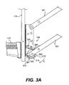
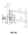
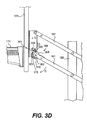
- FIGS. 3A-3E illustrate the incremental adjustment of the vertical height of the basketball backboard according to an embodiment of the present invention.
- FIG. 3A illustrates the basketball backboard 175 and hoop 170 at its second-lowest adjustable height
- FIG. 3E illustrates the basketball backboard 175 and hoop 170 at the highest adjustable height, with intermediate height adjustments illustrated in FIGS. 3B to 3D.
- FIG. 3A illustrates the pawl 320 engaging with tooth 2 of the toothed edge 304 and, as such, the basketball backboard 175 located at its second-lowest adjustable height.
- the first end of each of the elevator arms 141, 151 have a tendency to rotate downward about their point of connection with the support pole 120 (as shown in FIG. 1).
- the pawl 320 may engage with any one of the teeth 1-6 of the toothed edge 304 of the ratchet 301 so as to prevent further downward rotation by the elevator arms 141, 151. Therefore, when the pawl 320 is engaged with any one of the teeth 1-6 of the toothed edge 304, the basketball backboard and hoop 170 may be held at a selected vertical height for gameplay.
- a downward force is applied to the adjustment pole 160 in the direction of Arrow A (as shown in FIG. 1).
- the downward force causes the upper elevator arms 141, 142 and the lower elevator arms 151, 152 to pivot about their rotatable connections to accommodate adjustment of the vertical height of the backboard 175 and hoop 170.
- lower elevator arm 151 and ratchet 301 rotate about pin 302 in the direction of Arrow C such that the teeth 1-6 of the toothed edge 304 rotate under the pawl 320. Consequently, the pawl 320 rotates about pin 325 in the direction of Arrow D until the pawl 320 falls into engagement with the next tooth of the toothed edge 304.
- the force applied to the adjustment pole 160 may be removed and the engagement of the pawl 320 with one of the teeth 1-6 of the toothed edge 304 prevents further rotation of the elevator arms 141, 151 and ratchet 301.
- the basketball backboard 175 and hoop 170 are held at a pre-selected height above the playing surface. This process may be repeated, incrementally raising the height of the basketball backboard 175 and hoop 170.
- FIG. 3A shows pawl 320 in engagement with tooth 2 of the toothed edge 304.
- the elevator arms 141, 151 rotate about point 302 in the direction of Arrow C, causing the pawl 320 to rotate about pin 325 in the direction of Arrow D.
- the rotation of the elevator arms 141, 151 may continue until pawl 320 can fall into engagement with tooth 3, as shown in FIG. 3B.
- the pawl 320 remains engaged with tooth 3 of the toothed edge and the basketball backboard 175 and hoop 170 remain at the vertical height illustrated in FIG. 3B.
- the user may continue to apply force to the adjustment pole 160 which incrementally adjusts the height of the basketball backboard 175 and hoop 170 to any of the higher positions shown in FIGS. 3C, 3D or 3E. This process may be repeated until the basketball backboard 175 and hoop 170 reaches their maximum adjustable vertical height above the playing surface.
- the basketball backboard 175 and hoop 170 may be held at the maximum adjustable vertical height above the playing surface.
- the user may choose to allow the basketball backboard 175 and hoop 170 to remain at the highest height or may choose to lower the backboard 175 and hoop 170 back down to its lowest vertical height where the pawl 320 engages with tooth 1 of the toothed edge 304 of the ratchet 301.
- FIGS. 4A and 4B illustrate how a player may use the present invention to lower the basketball backboard 175 and hoop 170 from the maximum adjustable height.
- additional downwards force on the adjustment pole 160 causes pin 305 to exert a force on one end of the elongated slot 315 of the cam 310.
- This force causes the cam 310 to force the pawl 320 to rotate about pin 325 in the direction of Arrow D. This rotation results in the pawl disengaging from the teeth 1-6 of the toothed edge 304 of the ratchet 301 as illustrated in FIG. 4A.
- a user may lower the vertical height by allowing the basketball backboard 175 and hoop 170 to lower under its own weight or by exerting an upward force on the adjustment pole 160.
- the cam 310 remains stationary as the elongated slot 315 permits the ratchet 301 to move relative to the cam 310.
- the cam 310 continually holds the pawl 320 above the toothed edge 304 as the teeth 1-6 of the toothed edge pass below the pawl 320. Consequently, the cam 310 prevents the pawl 320 from engaging with any of the teeth 1-6 the toothed edge 304 and allows the user to lower the backboard 175 and hoop 170.
- pin 305 may engage the bottom end X of the elongated slot 315. This, in turn, causes the cam 310 to rotate counterclockwise with respect to the ratchet 301.
- the shape of the cam 310 may be such that, when the backboard 175 and hoop 170 reach the lowest vertical height, the pawl 320 is forced to engage with ratchet tooth 1 because the cam 310 may no longer lift the pawl 320 above the toothed edge 304. Once the pawl 320 engages with tooth 1 of the toothed edge 304, the height of the backboard 175 may again be incrementally increased, as discussed above with regard to FIGS. 3A-3E.
- the use of the ratchet and cam system 180 of the present invention may permit a user to automatically make adjustments in the height of a basketball system using a simple pole or similar device. Because the pawl 320 may automatically disengage from the ratchet teeth 304 to lower the height, a user may not be required to manually disengage a locking mechanism while supporting the weight of the assembly. As such, adjustments in the height of the basketball backboard 175 and hoop 170 may be made quickly and easily.
- ratchet 301, cam 310 and pawl 320 are of simple design and may be fabricated using readily available materials. As such, the assembly and use of the ratchet and cam system 180 is simple, time-efficient and cost-efficient.
Abstract
Description
- The present invention is related to an apparatus and method for adjusting the height of a basketball backboard assembly.
- Basketball has become an increasingly popular sport, with backyard and neighborhood basketball goals increasing in popularity. These backyard basketball goals often function well for families and communities with a wide variety of people playing the game, including grown adults and small children. Consequently, adjustable height basketball goals have become a favorite product in backyard or personal basketball courts as they allow individuals of various heights and skill levels to play on the same basketball goal.
- Many adjustable height basketball goals have been proposed for accomplishing incremental adjustment of the vertical height of a basketball backboard assembly. Such arrangements may often incorporate a parallelogram type support frame capable of permitting vertical movement of the backboard while maintaining a parallel relationship between the basketball rim and a playing surface. Additionally, various releasable locking arrangements have been proposed for holding the backboard assembly at a desired height.
- In many of these prior art systems, for a user to lower the height of the backboard assembly, the user must manually disengage a latch or other locking mechanism. Disengaging the latch permits the user to lower or raise the backboard until the goal is located at the desired height. The latch must then be engaged in order to lock the goal height. Other devices such as levers and/or switches, located behind the backboard and/or on handles extending down from the backboard, may activate the latch. Often, the latch needs to be activated and held open while adjusting the height of the backboard assembly. This may be especially difficult for some individuals, especially smaller children attempting to make height adjustments when the backboard is locked at its maximum height.
- Unfortunately, many prior art systems are complex and expensive, requiring multiple moving parts to control movement and lock the backboard in place. To reduce the complexity of the basketball goal elevator systems, some basketball goal assemblies include a ratchet system allowing the backboard and goal to be ratcheted up incrementally. A pole or other such element may be used to push the assembly upward.
- Unfortunately, upon reaching the last ratchet or the highest position, previous systems failed to return to the lowest height without manually disengaging the ratchet. In traditional systems, the disengaging of the ratchet included the use of an end of a long pole to disengage the pawl from the teeth of the ratchet before the backboard could be lowered. Once disengaged, the backboard would fall under its own weight to its lowest position before it was capable of being ratcheted up to a desired height. However, the release of the pawl typically required precise and difficult positioning of the end of the pole on the pawl located underneath or behind the backboard. This positioning of a pole may be especially difficult due to the small target that the pawl presents, a situation that may be made worse when the backboard is at the highest position.
- Furthermore, for some individuals, such as small children, the effort of positioning a long pole to both disengage the pawl and lower the weight of the backboard may be quite difficult. As a result, some individuals may be discouraged from changing the height of the backboard due to the difficulty of accurately releasing the pawl.
- Therefore, there is a need for an adjustable basketball backboard assembly that can be incrementally adjusted and easily lowered by individuals of various heights and skill levels.
- The present invention is related to an apparatus and method for adjusting the height of a basketball backboard assembly.
- One embodiment of the present invention includes a system for adjusting the height of a sports apparatus above a playing surface. The system may include a support element, a sports apparatus having at least a first position above the playing surface and a second position above the playing surface, the first position being lower than the second position, and at least one arm rotatably connected to the sports apparatus and rotatably connected to the support element. The system may also include a locking mechanism connected to the at least one arm and configured to permit the sports apparatus to move from the first position to the second position and to hold the sports apparatus at the first position and at the second position and a release element. The system may be configured so that the application of an upward force to the sports apparatus when the sports apparatus is at the first position causes the locking mechanism to permit the sports apparatus to move to the second position and the application of an upward force to the sports apparatus when the sports apparatus is at the second position causes the release element to unlock the locking mechanism to permit the sports apparatus to move from the second position to the first position.
- Another embodiment of the present invention may include a system for adjusting the height of a sports apparatus above a playing surface. The system may include a support element, a sports apparatus having at least a first position above the playing surface and a second position above the playing surface, the first position being lower than the second position, and at least one arm rotatably connected to the sports apparatus and rotatably connected to the support element. The system may also include means for maintaining the position of the sports apparatus at the first position and at the second position, the means for maintaining the position of the sports apparatus being further configured to permit the sports apparatus to move from the first position to the second position and means for releasing the sports apparatus from the second position. The system may be configured so that the application of an upward force to the sports apparatus when the sports apparatus is at the first position causes the means for maintaining the position of the sports apparatus to permit the sports apparatus to move to the second position and the application of an upward force to the sports apparatus when the sports apparatus is at the second position causes the means for releasing the sports apparatus to cause the means for maintaining the position of the sports apparatus to permit the sports apparatus to move from the second position to the first position.
- Another embodiment of the present invention may include an elevator system for adjusting the height of a basketball backboard above a playing surface. The system may include a basketball support element, a basketball backboard having at least a first position above the playing surface and a second position above the playing surface, the first position being lower than the second position, and at least one elevator arm rotatably connected to the backboard and rotatably connected to the basketball support element. The system may also include a ratchet having a plurality of ratchet teeth, the ratchet being rigidly connected to the at least one elevator arm, a pawl, the pawl being in engageable relation with the plurality of ratchet teeth when the backboard is at both the first position and the second position and capable of maintaining a position of the backboard above the playing surface and a cam rotatably connected to the ratchet and the backboard. The system may be configured so that the application of an upward force to the backboard when the backboard is at the first position causes the backboard to move to the second position and the application of an upward force to the backboard when the backboard is at the second position causes the cam to disengage the pawl from the ratchet, preventing the pawl from engaging with the plurality of ratchet teeth and permitting the backboard to move from the second position to the first position.
- Another embodiment of the present invention may include a method for adjusting the height of a basketball goal above a playing surface, the basketball goal having a backboard supported by a basketball support element and at least one elevator arm rotatably connected to both the support element and the backboard. The method may include the steps of securing the backboard at a first position by engaging a pawl with the teeth of a ratchet attached to the at least one elevator arm, applying an upwards force to the backboard to incrementally increase the height of the backboard above a playing surface until the backboard reaches a second position, whereupon a cam disengages the pawl from the ratchet teeth, lowering the backboard to the first position; and securing the backboard at the first position by engaging the pawl with the teeth of the ratchet.
- These and other objects and advantages of the invention will be apparent from the following description, the accompanying drawings and the appended claims.
- While the specification concludes with claims particularly pointing out and distinctly claiming the present invention, it is believed the same will be better understood from the following description taken in conjunction with the accompanying drawings, which illustrate, in a nonlimiting fashion, the best mode presently contemplated for carrying out the present invention, and in which like reference numerals designate like parts throughout the Figures, wherein:
- FIG. 1 shows an adjustable basketball goal system according to an embodiment of the present invention.
- FIG. 2 shows a side view of the various components of the present invention.
- FIGS. 3A-3E illustrate the incremental adjustment of the vertical height of the basketball backboard and hoop according to an embodiment of the present invention.
- FIGS. 4A and 4B illustrate how a player may use the present invention to lower a basketball backboard and hoop from its maximum adjustable height.
- The present disclosure will now be described more fully with reference to the Figures in which various embodiments of the present invention are shown. The subject matter of this disclosure may, however, be embodied in many different forms and should not be construed as being limited to the embodiments set forth herein.
- FIG. 1 shows an adjustable
basketball goal system 100 according to an embodiment of the present invention. Thebasketball goal system 100 may include arigid support pole 120 extending from abase 110 in a substantially upward direction. While the embodiment in FIG. 1 illustrates the use of amovable base 110, the system may also be used where thebasketball support pole 120 is fixed with respect to the playing surface (not shown). While the playing surface may be taken generally to mean the earth, it is also contemplated that thebasketball support pole 120 may be fixed in concrete, an indoor floor of the type found in gymnasiums, asphalt or any basketball playing surface as would be known by one of skill in the art. - Additionally, while FIG. 1 illustrates the use of a
pole 120 for supporting thebasketball goal system 100, it is further contemplated that the basketball goal system may be attached to any type of support element without deviating from the scope and spirit of the present invention. These support elements may include, for example, the wall of a building, a pre-existing post or any similar element to which a basketball goal system may be attached. - A
basketball backboard 175 andhoop 170 may be attached to thebasketball support pole 120 by anadjustable frame 130. Theadjustable frame 130 comprises twoupper elevator arms lower elevator arms upper elevator arms lower elevator arms - Each of the
upper elevator arms lower elevator arms support pole 120 using pins, screws, brackets or any other means known to one of skill in the art. Further, a first end of each of theupper elevator arms lower elevator arms basketball backboard 175 using pins, screws, brackets or any other means known to one of skill in the art. As shown in FIG. 1, theupper elevator arms lower elevator arms support pole 120 such that a second end of each of theupper elevator arms lower elevator arms adjustment pole 160 using pins, screws, brackets or any other means known to one of skill in the art. The embodiment illustrated in FIG. 1 may also include a ratchet andcam system 180 for incrementally raising and lowering the height of thebasketball backboard 175 andhoop 170 with the aid of theadjustment pole 160. - While FIG. 1 shows an
adjustment pole 160 rotatably attached to the second end of each of theelevator arms basketball backboard 175 andhoop 170. For example, in one embodiment, the adjustment pole may be a removable adjustment pole having one end configured to engage with the second end of any of theelevator arms elevator arms - Additionally, while FIG. 1 shows
elevator arms support pole 120, it is contemplated that the elevator arms may rotatably connect to thesupport pole 120 without extending beyond thesupport pole 120. In this embodiment, it is contemplated that any suitable adjustment pole may be used to exert a force on thebasketball backboard 175,hoop 170 or any of theelevator arms basketball backboard 175 andhoop 170. Further, it is contemplated that any mechanism that allows a user to exert a force in the direction of Arrow B on thebasketball backboard 175 andhoop 170 may be used in lieu of an adjustment pole. For example, the user may use a pole, a basketball, a block of wood or even the user's own hands to exert force on thebasketball backboard 175 andhoop 170. - As shown in FIG. 1, a releasable locking mechanism in the form of a ratchet and
cam system 180 may be located at one of the rotatable connections between thelower elevator arms basketball backboard 175. The ratchet andcam system 180 may be used to secure thebackboard 175 andhoop 170 at multiple pre-selected vertical heights above the ground or playing surface. While the figures illustrate a ratchet andcam system 180 connected at one of the rotatable connections between thelower elevator arms basketball backboard 175, it is contemplated that the ratchet andcam system 180 may be connected at any point where either of theupper elevator arms lower elevator arms basketball backboard 175. Additionally, it is contemplated that the ratchet andcam system 180 may be connected at any of the rotatable connections on theadjustable frame 130. These rotatable connections may include, for example, the points at which either of theupper elevator arms lower elevator arms support pole 120. Finally, it is contemplated that more than one ratchet andcam system 180 may be used at any number of the rotatable connections discussed above to add additional strength and stability to the elevator system. - FIG. 2 shows a side view of the various components of one embodiment of the present invention. As illustrated in FIG. 2, a
ratchet 301 is rigidly attached tolower elevator arm 151 using apin 303. It is also contemplated that screws, brackets or any other means known to one of skill in the art may be used to attachratchet 301 tolower elevator arm 151. While FIG. 2 illustrates asingle ratchet 301 attached to the outside oflower elevator arm 151, it is also contemplated that asingle ratchet 301 may be attached to the inside of lower elevator arm 151 (as illustrated in FIGS. 3A-3E). Further, theratchet 301 may be configured as an extension of thelower elevator arm 151, with two sets of ratchets positioned on either side of thelower elevator arm 151. Additionally, as would be apparent to one of skill in the art, thelower elevator arm 151 may extend to pin 302 and be rotatably connected to the backside of thebasketball backboard 175 directly. - A
pin 302 may be used to rotatably connect theratchet 301 and acam 310 to thebasketball backboard 175. It is also contemplated that screws, brackets or any other means known to one of skill in the art may be used to attach theratchet 301 andcam 310 to thebasketball backboard 175. Thecam 310 includes anelongated slot 315 configured to receive apin 305 which is connected to theratchet 301. Thepin 305 may serve to confine the rotation of thecam 310 aboutpin 302 to approximately 90 degrees with respect to theratchet 301. - A
pawl 320 may be rotatably attached tobasketball backboard 175 using apin 325 or screws, bolts or any other means known to one of skill in the art. Thepawl 320 is configured to engage with atoothed edge 304 ofratchet 301. The force of gravity may be used to urge thepawl 320 into engagement with one of the teeth 1-6 of thetoothed edge 304 on theratchet 301. Additionally, a spring (not shown) or other biasing means may be used to forcibly bias thepawl 320 in a downward direction into engagement with one of the teeth 1-6 of thetoothed edge 304. While FIG. 2 shows thetoothed edge 304 as having six teeth, it is contemplated that any number of teeth may be used without deviating from the scope and spirit of the present invention. - Further, while the figures illustrate the use of a
pawl 320 engaging with aratchet 301 for incrementally adjusting and locking the height of thebasketball backboard 175, it is also contemplated that additional mechanical arrangements may be used (not shown). This may include, for example, a series of holes located on either thebackboard 175 or one of theelevator arms backboard 175 or one of theelevator arms - The operation of the ratchet elevator system of the present invention will now be described with regard to FIGS. 3A-4B. FIGS. 3A-3E illustrate the incremental adjustment of the vertical height of the basketball backboard according to an embodiment of the present invention. FIG. 3A illustrates the
basketball backboard 175 andhoop 170 at its second-lowest adjustable height and FIG. 3E illustrates thebasketball backboard 175 andhoop 170 at the highest adjustable height, with intermediate height adjustments illustrated in FIGS. 3B to 3D. - FIG. 3A illustrates the
pawl 320 engaging withtooth 2 of thetoothed edge 304 and, as such, thebasketball backboard 175 located at its second-lowest adjustable height. Under the weight of thebackboard 175 andhoop 170, the first end of each of theelevator arms pawl 320 may engage with any one of the teeth 1-6 of thetoothed edge 304 of theratchet 301 so as to prevent further downward rotation by theelevator arms pawl 320 is engaged with any one of the teeth 1-6 of thetoothed edge 304, the basketball backboard andhoop 170 may be held at a selected vertical height for gameplay. - When a user desires to raise the
basketball backboard 175 andhoop 170, a downward force is applied to theadjustment pole 160 in the direction of Arrow A (as shown in FIG. 1). The downward force causes theupper elevator arms lower elevator arms backboard 175 andhoop 170. During this adjustment,lower elevator arm 151 and ratchet 301 rotate aboutpin 302 in the direction of Arrow C such that the teeth 1-6 of thetoothed edge 304 rotate under thepawl 320. Consequently, thepawl 320 rotates aboutpin 325 in the direction of Arrow D until thepawl 320 falls into engagement with the next tooth of thetoothed edge 304. - Once the
pawl 320 falls within the next tooth of thetoothed edge 304, the force applied to theadjustment pole 160 may be removed and the engagement of thepawl 320 with one of the teeth 1-6 of thetoothed edge 304 prevents further rotation of theelevator arms basketball backboard 175 andhoop 170 are held at a pre-selected height above the playing surface. This process may be repeated, incrementally raising the height of thebasketball backboard 175 andhoop 170. - A comparison of FIG. 3A with FIG. 3B illustrates the incremental adjustment in the height of the
basketball backboard 175 andhoop 170 according to the present invention. FIG. 3A showspawl 320 in engagement withtooth 2 of thetoothed edge 304. When a user applies a downward force to theadjustment pole 160, theelevator arms point 302 in the direction of Arrow C, causing thepawl 320 to rotate aboutpin 325 in the direction of Arrow D. The rotation of theelevator arms pawl 320 can fall into engagement with tooth 3, as shown in FIG. 3B. If a user elects to remove the force in the direction of Arrow A onadjustment pole 160, thepawl 320 remains engaged with tooth 3 of the toothed edge and thebasketball backboard 175 andhoop 170 remain at the vertical height illustrated in FIG. 3B. Alternatively, the user may continue to apply force to theadjustment pole 160 which incrementally adjusts the height of thebasketball backboard 175 andhoop 170 to any of the higher positions shown in FIGS. 3C, 3D or 3E. This process may be repeated until thebasketball backboard 175 andhoop 170 reaches their maximum adjustable vertical height above the playing surface. - As illustrated in FIG. 3E, when the
pawl 320 engages with the final tooth 6 of thetoothed edge 304, thebasketball backboard 175 andhoop 170 may be held at the maximum adjustable vertical height above the playing surface. At this point, the user may choose to allow thebasketball backboard 175 andhoop 170 to remain at the highest height or may choose to lower thebackboard 175 andhoop 170 back down to its lowest vertical height where thepawl 320 engages withtooth 1 of thetoothed edge 304 of theratchet 301. - FIGS. 4A and 4B illustrate how a player may use the present invention to lower the
basketball backboard 175 andhoop 170 from the maximum adjustable height. When thebackboard 175 andhoop 170 reach the maximum vertical height, additional downwards force on theadjustment pole 160 causespin 305 to exert a force on one end of theelongated slot 315 of thecam 310. This force causes thecam 310 to force thepawl 320 to rotate aboutpin 325 in the direction of Arrow D. This rotation results in the pawl disengaging from the teeth 1-6 of thetoothed edge 304 of theratchet 301 as illustrated in FIG. 4A. - Once the
pawl 320 is disengaged from the teeth 1-6 of thetoothed edge 304, a user may lower the vertical height by allowing thebasketball backboard 175 andhoop 170 to lower under its own weight or by exerting an upward force on theadjustment pole 160. As theelevator arms cam 310 remains stationary as theelongated slot 315 permits theratchet 301 to move relative to thecam 310. As shown in FIG. 4B, thecam 310 continually holds thepawl 320 above thetoothed edge 304 as the teeth 1-6 of the toothed edge pass below thepawl 320. Consequently, thecam 310 prevents thepawl 320 from engaging with any of the teeth 1-6 thetoothed edge 304 and allows the user to lower thebackboard 175 andhoop 170. - When the
backboard 175 andhoop 170 almost reach the lowest vertical height, pin 305 may engage the bottom end X of theelongated slot 315. This, in turn, causes thecam 310 to rotate counterclockwise with respect to theratchet 301. The shape of thecam 310 may be such that, when thebackboard 175 andhoop 170 reach the lowest vertical height, thepawl 320 is forced to engage withratchet tooth 1 because thecam 310 may no longer lift thepawl 320 above thetoothed edge 304. Once thepawl 320 engages withtooth 1 of thetoothed edge 304, the height of thebackboard 175 may again be incrementally increased, as discussed above with regard to FIGS. 3A-3E. - Unlike traditional systems, the use of the ratchet and
cam system 180 of the present invention may permit a user to automatically make adjustments in the height of a basketball system using a simple pole or similar device. Because thepawl 320 may automatically disengage from theratchet teeth 304 to lower the height, a user may not be required to manually disengage a locking mechanism while supporting the weight of the assembly. As such, adjustments in the height of thebasketball backboard 175 andhoop 170 may be made quickly and easily. - Further, it should be noted that the
ratchet 301,cam 310 andpawl 320 are of simple design and may be fabricated using readily available materials. As such, the assembly and use of the ratchet andcam system 180 is simple, time-efficient and cost-efficient. - The foregoing descriptions of specific embodiments of the present invention are presented for purposes of illustration and description. They are not intended to be exhaustive or to limit the invention to the precise forms disclosed. Obviously, many modifications and variations are possible in view of the above teachings. While the embodiments were chosen and described in order to best explain the principles of the invention and its practical applications, thereby enabling others skilled in the art to best utilize the invention, various embodiments with various modifications as are suited to the particular use are also possible. The scope of the invention is to be defined only by the claims appended hereto, and by their equivalents.
Claims (22)
- A system for adjusting the height of a sports apparatus above a playing surface, the system comprising:a support element;a sports apparatus having at least a first position above said playing surface and a second position above said playing surface, the first position being lower than the second position;at least one arm rotatably connected to said sports apparatus and rotatably connected to said support element;a locking mechanism connected to said at least one arm and configured to permit said sports apparatus to move from the first position to the second position and to hold the sports apparatus at the first position and at the second position; anda release element;wherein the application of an upward force to said sports apparatus when said sports apparatus is at the first position causes said locking mechanism to permit said sports apparatus to move to said second position and the application of an upward force to said sports apparatus when said sports apparatus is at the second position causes said release element to unlock said locking mechanism to permit said sports apparatus to move from the second position to the first position.
- The system of claim 1, wherein said sports apparatus comprises a basketball backboard and hoop.
- The system of claim 1, wherein said locking mechanism comprises:a ratchet having a plurality of teeth; anda pawl in engageable relation with the plurality of teeth.
- The system of claim 3, wherein said pawl is biased into engageable relation with the plurality of teeth.
- The system of claim 3, wherein said release element comprises a cam, said cam being configured to disengage said pawl from the plurality of teeth to permit said sports apparatus to move from the second position to the first position.
- The system of claim 1, wherein said locking mechanism comprises:a plurality of holes; anda pin in engageable relation with said plurality of holes.
- The system of claim 6, wherein said pin is biased into engageable relation with said plurality of holes.
- The system of claim 6, wherein said release element comprises a cam, said cam being configured to disengage said pin from said plurality of holes to permit said sports apparatus to move from the second position to the first position.
- The system of claim 1, wherein said locking mechanism comprises:a plurality of slots; anda blade in engageable relation with said plurality of slots.
- The system of claim 9, wherein said blade is biased into engageable relation with said plurality of slots.
- The system of claim 9, wherein said release element comprises a cam, said cam being configured to disengage said blade from said plurality of slots to permit said sports apparatus to move from the second position to the first position.
- A system for adjusting the height of a sports apparatus above a playing surface, the system comprising:a support element;a sports apparatus having at least a first position above said playing surface and a second position above said playing surface, the first position being lower than the second position;at least one arm rotatably connected to said sports apparatus and rotatably connected to said support element;means for maintaining the position of said sports apparatus at the first position and at the second position, said means for maintaining the position of said sports apparatus being further configured to permit said sports apparatus to move from the first position to the second position; andmeans for releasing said sports apparatus from the second position;wherein the application of an upward force to said sports apparatus when said sports apparatus is at the first position causes said means for maintaining the position of said sports apparatus to permit said sports apparatus to move to said second position and the application of an upward force to said sports apparatus when said sports apparatus is at the second position causes said means for releasing said sports apparatus to cause said means for maintaining the position of said sports apparatus to permit said sports apparatus to move from the second position to the first position.
- An elevator system for adjusting the height of a basketball backboard above a playing surface, the system comprising:a basketball support element;a basketball backboard having at least a first position above said playing surface and a second position above said playing surface, the first position being lower than the second position;at least one elevator arm rotatably connected to said backboard and rotatably connected to said basketball support element;a ratchet having a plurality of ratchet teeth, said ratchet being rigidly connected to said at least one elevator arm;a pawl, said pawl being in engageable relation with the plurality of ratchet teeth when said backboard is at both the first position and the second position and capable of maintaining a position of said backboard above said playing surface; anda cam rotatably connected to said ratchet and said backboard;wherein the application of an upward force to said backboard when said backboard is at the first position causes said backboard to move to said second position and the application of an upward force to said backboard when said backboard is at the second position causes said cam to disengage said pawl from said ratchet, preventing said pawl from engaging with the plurality of ratchet teeth and permitting said backboard to move from the second position to the first position.
- The system according to claim 13, wherein:said cam has a slot with a first end and a second end; andsaid ratchet has a pin in slidable engagement with the slot, the pin engaging the first end of the slot when said backboard is located at the first position and the second position and engaging with the second end of the slot during the movement of said backboard from the second position to the first position.
- The system according to claim 13, further comprising an adjustment pole for applying an upward force to said backboard.
- The system according to claim 13, wherein the first position is the lowest possible vertical position of said backboard above said playing surface.
- The system according to claim 13, wherein the second position is the highest possible vertical position of said backboard above said playing surface.
- A method for adjusting the height of a basketball goal above a playing surface, the basketball goal having a backboard supported by a basketball support element and at least one elevator arm rotatably connected to both the support element and the backboard, the method comprising:securing the backboard at a first position by engaging a pawl with the teeth of a ratchet attached to the at least one elevator arm;applying an upwards force to the backboard to incrementally increase the height of the backboard above a playing surface until the backboard reaches a second position, whereupon a cam disengages the pawl from the ratchet teeth;lowering the backboard to the first position; andsecuring the backboard at the first position by engaging the pawl with the teeth of the ratchet.
- The method of claim 18, wherein the step of applying an upwards force to the backboard is performed using an adjustment pole attached to the at least one elevator arm.
- The method of claim 19, wherein the adjustment pole is removably attached to the at least one elevator arm.
- The method according to claim 18, wherein the first position is the lowest possible vertical position of the backboard above the playing surface.
- The method according to claim 18, wherein the second position is the highest possible vertical position of said backboard.
Priority Applications (1)
| Application Number | Priority Date | Filing Date | Title |
|---|---|---|---|
| PL06120657T PL1772169T3 (en) | 2005-09-29 | 2006-09-14 | Ratchet elevator system |
Applications Claiming Priority (1)
| Application Number | Priority Date | Filing Date | Title |
|---|---|---|---|
| US11/238,132 US7335119B2 (en) | 2005-09-29 | 2005-09-29 | Ratchet elevator system |
Publications (2)
| Publication Number | Publication Date |
|---|---|
| EP1772169A1 true EP1772169A1 (en) | 2007-04-11 |
| EP1772169B1 EP1772169B1 (en) | 2008-12-03 |
Family
ID=37507691
Family Applications (1)
| Application Number | Title | Priority Date | Filing Date |
|---|---|---|---|
| EP06120657A Not-in-force EP1772169B1 (en) | 2005-09-29 | 2006-09-14 | Ratchet elevator system |
Country Status (10)
| Country | Link |
|---|---|
| US (1) | US7335119B2 (en) |
| EP (1) | EP1772169B1 (en) |
| CN (1) | CN1939558A (en) |
| AT (1) | ATE416014T1 (en) |
| DE (1) | DE602006003977D1 (en) |
| DK (1) | DK1772169T3 (en) |
| ES (1) | ES2317438T3 (en) |
| HK (1) | HK1097211A1 (en) |
| PL (1) | PL1772169T3 (en) |
| PT (1) | PT1772169E (en) |
Families Citing this family (11)
| Publication number | Priority date | Publication date | Assignee | Title |
|---|---|---|---|---|
| JP4530296B2 (en) | 2008-04-09 | 2010-08-25 | Necアクセステクニカ株式会社 | Variable angle structure |
| US8043174B2 (en) * | 2008-07-09 | 2011-10-25 | Gared Holdings, Llc | Goal height adjuster lock |
| EP2414235B1 (en) | 2009-03-30 | 2015-08-26 | Zodiac Seats US LLC | Deployment apparatuses |
| US9239128B2 (en) * | 2011-05-31 | 2016-01-19 | Canon Kabushiki Kaisha | Image forming apapratus |
| US10322805B2 (en) | 2013-01-07 | 2019-06-18 | Safran Seats Usa Llc | Video arm deployment method |
| GB201820948D0 (en) * | 2018-12-21 | 2019-02-06 | Mark Harrod Ltd | System for use with a moveable sports apparatus |
| USD992665S1 (en) * | 2020-01-08 | 2023-07-18 | P&P Imports LLC | Basketball hoop support |
| USD1004017S1 (en) * | 2020-01-08 | 2023-11-07 | P&P Imports LLC | Basketball hoop base |
| USD1006155S1 (en) * | 2021-07-01 | 2023-11-28 | P&P Imports LLC | Basketball goal assembly |
| USD977601S1 (en) * | 2022-01-10 | 2023-02-07 | Meijuan Zheng | Basketball stand |
| USD1019836S1 (en) * | 2023-10-27 | 2024-03-26 | Xinjiang Huang | Basketball stand |
Citations (3)
| Publication number | Priority date | Publication date | Assignee | Title |
|---|---|---|---|---|
| US4330101A (en) * | 1979-10-31 | 1982-05-18 | Equalizer, Inc. | Basketball backboard support apparatus |
| US4684129A (en) * | 1986-03-24 | 1987-08-04 | Andersen Manufacturing, Inc. | Basketball standard and adjustable support strut therefor |
| US5292118A (en) * | 1992-01-31 | 1994-03-08 | Huffy Corporation | Basketball backboard elevator system |
Family Cites Families (84)
| Publication number | Priority date | Publication date | Assignee | Title |
|---|---|---|---|---|
| US1139581A (en) * | 1915-05-18 | Cleveland Dental Mfg Company | Dental tray. | |
| US289653A (en) * | 1883-12-04 | Assigkoe to h | ||
| US482207A (en) * | 1892-09-06 | Adjustable swinging bracket | ||
| US532132A (en) * | 1895-01-08 | Game apparatus | ||
| US169382A (en) * | 1875-11-02 | Improvement in adjustable brackets | ||
| US213775A (en) * | 1879-04-01 | Improvement in adjustable brackets | ||
| US171746A (en) * | 1876-01-04 | Improvement in adjustable brackets | ||
| US446464A (en) * | 1891-02-17 | nittiiger | ||
| US78570A (en) * | 1868-06-02 | Improved oae-seat and chaie | ||
| US480261A (en) * | 1892-08-09 | Dental cabinet | ||
| US325551A (en) * | 1885-09-01 | Head-rest for embalming-tables | ||
| US806790A (en) * | 1905-03-06 | 1905-12-12 | Henry F Foersterling | Telephone-bracket. |
| US876525A (en) * | 1906-12-31 | 1908-01-14 | Franklin Chichester | Chair-iron. |
| US1192811A (en) * | 1910-11-25 | 1916-07-25 | Max W Zabel | Horological instrument. |
| US1050672A (en) * | 1911-06-02 | 1913-01-14 | James H B Macintosh | Dental wall-bracket. |
| CH137428A (en) * | 1929-04-04 | 1930-01-15 | Landis & Gyr Ag | Height-adjustable chair. |
| US1924811A (en) | 1931-11-02 | 1933-08-29 | Otto C Schulz | Basket ball backstop |
| US2227310A (en) * | 1939-05-23 | 1940-12-31 | Everwear Mfg Company | Basket-ball backstop apparatus |
| US2313188A (en) * | 1940-08-26 | 1943-03-09 | Chester C Woodburn | Adjustable goal for basketball courts |
| US2391872A (en) * | 1943-04-13 | 1946-01-01 | Berg Quentin | Driver's seat |
| US2379572A (en) * | 1943-07-09 | 1945-07-03 | Gerald A Gibson | Portable basketball goal |
| US2557604A (en) * | 1949-11-22 | 1951-06-19 | Cosmo L Invidiato | Surgical brace and pivotal joint therefor |
| FR1095140A (en) * | 1953-03-16 | 1955-05-27 | Happich Gmbh Gebr | Backrest for motor vehicles, adjustable in position from the seat, and using a handle |
| US2986395A (en) * | 1957-02-04 | 1961-05-30 | Sheftel Harry | Adjustable basketball goal |
| US3017183A (en) * | 1960-03-25 | 1962-01-16 | Charles P Chalcroft | Portable basketball goal assembly |
| US3237902A (en) * | 1963-06-03 | 1966-03-01 | Morita Mfg | Dental tray supporting mechanism |
| US3341197A (en) * | 1963-12-11 | 1967-09-12 | Richard D Bottorff | Adjustable game target mast apparatus |
| US3329427A (en) * | 1964-01-16 | 1967-07-04 | Darrell W Bearson | Adjustable basketball goal |
| DE1425970C2 (en) * | 1964-02-10 | 1973-09-20 | Kurz Gmbh, 7120 Bietigheim | Joint, especially for folding furniture or the like |
| GB1149761A (en) * | 1965-01-14 | 1969-04-23 | Zealand Engineering Company Lt | Improvements in or relating to adjustable self-locking joints |
| US3467377A (en) * | 1966-08-01 | 1969-09-16 | Evans Mfg Co Jackes | Foldable backstop down-lock means |
| US3490727A (en) * | 1967-09-08 | 1970-01-20 | Harvey Q Miller | Holding apparatus for loads adapted to be strapped to the back of humans |
| US3462102A (en) * | 1968-01-22 | 1969-08-19 | Walter Rivers | Auxiliary motor mounting bracket |
| US3614099A (en) * | 1969-02-26 | 1971-10-19 | Automatic Sprinkler Corp | Retractable overhead basketball backboard support structure |
| US3586324A (en) * | 1969-04-14 | 1971-06-22 | Goals Inc | Vertically adjustable basketball goal |
| US3765676A (en) * | 1971-01-15 | 1973-10-16 | B Bearson | Adjustable basketball goals |
| US3880392A (en) * | 1973-02-15 | 1975-04-29 | Joseph W Duganich | Wide bearing wedge lock |
| US3802702A (en) * | 1973-03-07 | 1974-04-09 | Equalizer Inc | Support structure for basketball board and hoop combinations |
| US4465277A (en) * | 1976-07-21 | 1984-08-14 | Dunk King Inc. | Basketball goal structure |
| US4151989A (en) * | 1976-07-21 | 1979-05-01 | Dunk King Inc. | Basketball practice device |
| US4145044A (en) * | 1977-03-07 | 1979-03-20 | The Ohio Art Company | Portable basketball set |
| US4412679A (en) * | 1978-09-27 | 1983-11-01 | Mahoney Elmo J | Foldable basketball goal means |
| GB2032770A (en) * | 1978-11-01 | 1980-05-14 | Uop Inc | Adjustable armrests |
| US4395040A (en) * | 1982-04-12 | 1983-07-26 | David White | Adjustable basketball goal |
| JPS60191245U (en) * | 1984-05-31 | 1985-12-18 | 株式会社タチエス | Headrest device for vehicle seats, etc. |
| US4793611A (en) * | 1986-09-10 | 1988-12-27 | Spang & Company | Adjustable height toy basketball goal |
| US4781375A (en) * | 1986-10-21 | 1988-11-01 | Lifetime Products, Inc. | Method and apparatus for adjusting a basketball goal |
| US4805904A (en) * | 1986-10-21 | 1989-02-21 | Lifetime Products, Inc. | Method and apparatus for adjusting a basketball goal |
| US4881734A (en) * | 1986-10-21 | 1989-11-21 | Lifetime Products, Inc. | Method and apparatus for adjusting a basketball goal |
| AU585402B2 (en) * | 1986-11-07 | 1989-06-15 | Tachi-S Co., Ltd. | Reclining device |
| US4798381A (en) * | 1987-07-06 | 1989-01-17 | Harvard Sports, Inc. | Basketball goal height adjustment apparatus |
| US4828323A (en) * | 1988-06-20 | 1989-05-09 | Sears Manufacturing Company | Adjustable armrest |
| US5082261A (en) * | 1988-11-14 | 1992-01-21 | The Little Tikes Company | Basketball stand |
| US5133547A (en) * | 1991-01-22 | 1992-07-28 | Jayfro Corporation | Self-adjusting basketball goal |
| US5503390A (en) * | 1991-03-19 | 1996-04-02 | Hall; Timothy D. | Adjustable basketball backboard support system |
| US5211393A (en) * | 1991-10-16 | 1993-05-18 | Goalsetter Systems, Inc. | Adjustable basketball goal |
| US5720679A (en) * | 1992-05-27 | 1998-02-24 | Porter Athletic Equipment Company | Adjustable basketball backboard support system |
| US5478068A (en) * | 1992-07-30 | 1995-12-26 | Porter Athletic Equipment Company | Wheeled portable basketball goal assembly |
| US5354049A (en) * | 1992-09-08 | 1994-10-11 | Matherne Lonny R | Apparatus and method for packaging a portable basketball system |
| US5377976A (en) * | 1993-02-04 | 1995-01-03 | Lifetime Products, Inc. | Portable basketball system |
| US5401015A (en) * | 1993-07-15 | 1995-03-28 | Woodall; Bliss T. | Adjustable basketball goal |
| US5540429A (en) * | 1993-12-30 | 1996-07-30 | Icon Health & Fitness, Inc. | Adjustable height basketball standard with telescoping tubes |
| US5462269A (en) * | 1994-03-21 | 1995-10-31 | Porter Athletic Equipment Company | Adjustable backboard assembly with drive lock |
| US5484127A (en) * | 1994-07-15 | 1996-01-16 | Lifetime Products, Inc. | Angled support brace |
| US5601284A (en) * | 1996-02-12 | 1997-02-11 | Blackwell; Scott | Adjustable basketball goal |
| US5738601A (en) * | 1996-03-14 | 1998-04-14 | Hughes; Todd R. | Height adjustable basketball goal assembly |
| US5826846A (en) * | 1996-06-28 | 1998-10-27 | Hill-Rom, Inc. | Monitor arm with constant counterbalance |
| US5772167A (en) * | 1996-07-29 | 1998-06-30 | Schelde International B.V. | Basketball-stand |
| US5695417A (en) * | 1997-02-12 | 1997-12-09 | Winter; David C. | Power lift basketball adjustment system |
| US6422957B1 (en) * | 1997-02-12 | 2002-07-23 | Lifetime Products, Inc. | Quick-release self-adjusting slide collar mechanism for height adjustment of a basketball apparatus |
| US6699146B1 (en) * | 1997-02-12 | 2004-03-02 | Lifetime Products, Inc. | Parallelogrammic adjustment assembly for basketball goal systems |
| US6419597B1 (en) * | 1997-02-12 | 2002-07-16 | Lifetime Products, Inc. | Electromechanical compression crank adjustment mechanism for a basketball goal assembly |
| US6402644B2 (en) * | 1997-02-12 | 2002-06-11 | Lifetime Products, Inc. | Constant force adjustable basketball goal assembly |
| US6077177A (en) * | 1997-02-12 | 2000-06-20 | Lifetime Products, Inc. | Adjustable basketball goal system |
| US6155938A (en) * | 1997-02-12 | 2000-12-05 | Lifetime Products, Inc. | Basketball goal assembly having one-handed push button height adjustment mechanism |
| US6645095B1 (en) * | 1997-02-12 | 2003-11-11 | Lifetime Products, Inc. | Slide collar adjustment mechanism for a basketball goal assembly |
| US6273834B1 (en) * | 1997-02-12 | 2001-08-14 | Lifetime Products, Inc. | Quick-release self-adjusting latch for adjustable basketball goal assembly |
| US6120396A (en) | 1997-02-12 | 2000-09-19 | Lifetime Products, Inc. | Quick-release locking mechanism for adjustable basketball goal system and methods for using same |
| US5800296A (en) * | 1997-05-01 | 1998-09-01 | Jaypro Sports, Inc. | Height adjusted backboard |
| US5823898A (en) * | 1997-10-09 | 1998-10-20 | Wang; Lian-Cheng | Assembly adapted for use both as a basketball backboard and a boxing training apparatus |
| US6283878B1 (en) * | 1999-03-11 | 2001-09-04 | Huffy Corporation | Adjustable height basketball apparatus |
| US20020094890A1 (en) * | 2001-01-16 | 2002-07-18 | Ron White | Adjustable basketball apparatus |
| US7097574B2 (en) | 2002-12-16 | 2006-08-29 | Lifetime Products, Inc. | Basketball system |
| US20060276273A1 (en) * | 2005-06-01 | 2006-12-07 | Perry Robert S | Portable basketball assembly for use on trailer hitches with integrated telescoping pole, foldable backboard and rim, and anti-rattle device element |
-
2005
- 2005-09-29 US US11/238,132 patent/US7335119B2/en active Active
-
2006
- 2006-09-14 AT AT06120657T patent/ATE416014T1/en active
- 2006-09-14 EP EP06120657A patent/EP1772169B1/en not_active Not-in-force
- 2006-09-14 ES ES06120657T patent/ES2317438T3/en active Active
- 2006-09-14 PL PL06120657T patent/PL1772169T3/en unknown
- 2006-09-14 PT PT06120657T patent/PT1772169E/en unknown
- 2006-09-14 DK DK06120657T patent/DK1772169T3/en active
- 2006-09-14 DE DE602006003977T patent/DE602006003977D1/en active Active
- 2006-09-21 CN CNA2006101270499A patent/CN1939558A/en active Pending
-
2007
- 2007-04-16 HK HK07103970.1A patent/HK1097211A1/en unknown
Patent Citations (3)
| Publication number | Priority date | Publication date | Assignee | Title |
|---|---|---|---|---|
| US4330101A (en) * | 1979-10-31 | 1982-05-18 | Equalizer, Inc. | Basketball backboard support apparatus |
| US4684129A (en) * | 1986-03-24 | 1987-08-04 | Andersen Manufacturing, Inc. | Basketball standard and adjustable support strut therefor |
| US5292118A (en) * | 1992-01-31 | 1994-03-08 | Huffy Corporation | Basketball backboard elevator system |
Also Published As
| Publication number | Publication date |
|---|---|
| US7335119B2 (en) | 2008-02-26 |
| CN1939558A (en) | 2007-04-04 |
| DK1772169T3 (en) | 2009-02-23 |
| DE602006003977D1 (en) | 2009-01-15 |
| ES2317438T3 (en) | 2009-04-16 |
| PL1772169T3 (en) | 2009-06-30 |
| PT1772169E (en) | 2009-01-13 |
| US20070072706A1 (en) | 2007-03-29 |
| ATE416014T1 (en) | 2008-12-15 |
| EP1772169B1 (en) | 2008-12-03 |
| HK1097211A1 (en) | 2007-06-22 |
Similar Documents
| Publication | Publication Date | Title |
|---|---|---|
| US7335119B2 (en) | Ratchet elevator system | |
| JP2774850B2 (en) | Adjustable basketball goals and methods | |
| US6264586B1 (en) | Foldable exercise bench | |
| US4781375A (en) | Method and apparatus for adjusting a basketball goal | |
| US5879247A (en) | Power lift basketball adjustment system | |
| US6142891A (en) | Adjustable basketball goal system | |
| US5830114A (en) | Variable incline folding exerciser | |
| US7462117B2 (en) | Ground anchor for sports support pole | |
| US20040023760A1 (en) | Collapsible seat for combination hack squat and leg press machine | |
| US11766585B2 (en) | Folding exercise rack system | |
| JP2001246015A (en) | Exercising machine | |
| US20090118104A1 (en) | AB-Exerciser bench | |
| US20230057347A1 (en) | Exercise apparatus | |
| US20060191745A1 (en) | Adjustable leg extension | |
| EP1767252A1 (en) | Apparatus and method for adjusting the height of a basketball backboard and hoop | |
| US8496538B1 (en) | Tilting golf practice platform | |
| US20210346774A1 (en) | Adjustable basketball goal | |
| KR200468700Y1 (en) | An apparatus for moving up and down a foot plate | |
| CN1361670A (en) | Portable seating and locking apparatus therefor | |
| US6994661B1 (en) | Tiltable exercise bench | |
| US20060076190A1 (en) | Step ladder | |
| EP2217112B1 (en) | Folding seat, spectator stand element and support member for seat | |
| JP3842937B2 (en) | Continuous impact sound generator | |
| JPH0539563U (en) | Training bench | |
| CN215691658U (en) | Run-up convenient to adjust |
Legal Events
| Date | Code | Title | Description |
|---|---|---|---|
| PUAI | Public reference made under article 153(3) epc to a published international application that has entered the european phase |
Free format text: ORIGINAL CODE: 0009012 |
|
| AK | Designated contracting states |
Kind code of ref document: A1 Designated state(s): AT BE BG CH CY CZ DE DK EE ES FI FR GB GR HU IE IS IT LI LT LU LV MC NL PL PT RO SE SI SK TR |
|
| AX | Request for extension of the european patent |
Extension state: AL BA HR MK YU |
|
| 17P | Request for examination filed |
Effective date: 20070417 |
|
| 17Q | First examination report despatched |
Effective date: 20070524 |
|
| REG | Reference to a national code |
Ref country code: HK Ref legal event code: DE Ref document number: 1097211 Country of ref document: HK |
|
| AKX | Designation fees paid |
Designated state(s): AT BE BG CH CY CZ DE DK EE ES FI FR GB GR HU IE IS IT LI LT LU LV MC NL PL PT RO SE SI SK TR |
|
| GRAP | Despatch of communication of intention to grant a patent |
Free format text: ORIGINAL CODE: EPIDOSNIGR1 |
|
| GRAS | Grant fee paid |
Free format text: ORIGINAL CODE: EPIDOSNIGR3 |
|
| GRAA | (expected) grant |
Free format text: ORIGINAL CODE: 0009210 |
|
| AK | Designated contracting states |
Kind code of ref document: B1 Designated state(s): AT BE BG CH CY CZ DE DK EE ES FI FR GB GR HU IE IS IT LI LT LU LV MC NL PL PT RO SE SI SK TR |
|
| REG | Reference to a national code |
Ref country code: GB Ref legal event code: FG4D |
|
| REG | Reference to a national code |
Ref country code: CH Ref legal event code: EP |
|
| REG | Reference to a national code |
Ref country code: IE Ref legal event code: FG4D |
|
| REG | Reference to a national code |
Ref country code: PT Ref legal event code: SC4A Free format text: AVAILABILITY OF NATIONAL TRANSLATION Effective date: 20081231 |
|
| REF | Corresponds to: |
Ref document number: 602006003977 Country of ref document: DE Date of ref document: 20090115 Kind code of ref document: P |
|
| REG | Reference to a national code |
Ref country code: CH Ref legal event code: NV Representative=s name: SERVOPATENT GMBH |
|
| REG | Reference to a national code |
Ref country code: RO Ref legal event code: EPE |
|
| REG | Reference to a national code |
Ref country code: GR Ref legal event code: EP Ref document number: 20090400118 Country of ref document: GR |
|
| REG | Reference to a national code |
Ref country code: DK Ref legal event code: T3 |
|
| REG | Reference to a national code |
Ref country code: SE Ref legal event code: TRGR |
|
| REG | Reference to a national code |
Ref country code: ES Ref legal event code: FG2A Ref document number: 2317438 Country of ref document: ES Kind code of ref document: T3 |
|
| PG25 | Lapsed in a contracting state [announced via postgrant information from national office to epo] |
Ref country code: LT Free format text: LAPSE BECAUSE OF FAILURE TO SUBMIT A TRANSLATION OF THE DESCRIPTION OR TO PAY THE FEE WITHIN THE PRESCRIBED TIME-LIMIT Effective date: 20081203 |
|
| NLV1 | Nl: lapsed or annulled due to failure to fulfill the requirements of art. 29p and 29m of the patents act | ||
| PG25 | Lapsed in a contracting state [announced via postgrant information from national office to epo] |
Ref country code: NL Free format text: LAPSE BECAUSE OF FAILURE TO SUBMIT A TRANSLATION OF THE DESCRIPTION OR TO PAY THE FEE WITHIN THE PRESCRIBED TIME-LIMIT Effective date: 20081203 Ref country code: SI Free format text: LAPSE BECAUSE OF FAILURE TO SUBMIT A TRANSLATION OF THE DESCRIPTION OR TO PAY THE FEE WITHIN THE PRESCRIBED TIME-LIMIT Effective date: 20081203 Ref country code: LV Free format text: LAPSE BECAUSE OF FAILURE TO SUBMIT A TRANSLATION OF THE DESCRIPTION OR TO PAY THE FEE WITHIN THE PRESCRIBED TIME-LIMIT Effective date: 20081203 |
|
| REG | Reference to a national code |
Ref country code: HU Ref legal event code: AG4A Ref document number: E004977 Country of ref document: HU |
|
| REG | Reference to a national code |
Ref country code: PL Ref legal event code: T3 |
|
| PG25 | Lapsed in a contracting state [announced via postgrant information from national office to epo] |
Ref country code: EE Free format text: LAPSE BECAUSE OF FAILURE TO SUBMIT A TRANSLATION OF THE DESCRIPTION OR TO PAY THE FEE WITHIN THE PRESCRIBED TIME-LIMIT Effective date: 20081203 |
|
| REG | Reference to a national code |
Ref country code: HK Ref legal event code: GR Ref document number: 1097211 Country of ref document: HK |
|
| PG25 | Lapsed in a contracting state [announced via postgrant information from national office to epo] |
Ref country code: IS Free format text: LAPSE BECAUSE OF FAILURE TO SUBMIT A TRANSLATION OF THE DESCRIPTION OR TO PAY THE FEE WITHIN THE PRESCRIBED TIME-LIMIT Effective date: 20090403 |
|
| PG25 | Lapsed in a contracting state [announced via postgrant information from national office to epo] |
Ref country code: SK Free format text: LAPSE BECAUSE OF FAILURE TO SUBMIT A TRANSLATION OF THE DESCRIPTION OR TO PAY THE FEE WITHIN THE PRESCRIBED TIME-LIMIT Effective date: 20081203 |
|
| PLBE | No opposition filed within time limit |
Free format text: ORIGINAL CODE: 0009261 |
|
| STAA | Information on the status of an ep patent application or granted ep patent |
Free format text: STATUS: NO OPPOSITION FILED WITHIN TIME LIMIT |
|
| 26N | No opposition filed |
Effective date: 20090904 |
|
| PGFP | Annual fee paid to national office [announced via postgrant information from national office to epo] |
Ref country code: AT Payment date: 20090911 Year of fee payment: 4 Ref country code: CZ Payment date: 20090903 Year of fee payment: 4 Ref country code: PL Payment date: 20090901 Year of fee payment: 4 Ref country code: PT Payment date: 20090914 Year of fee payment: 4 Ref country code: RO Payment date: 20090812 Year of fee payment: 4 |
|
| PGFP | Annual fee paid to national office [announced via postgrant information from national office to epo] |
Ref country code: BG Payment date: 20090817 Year of fee payment: 4 Ref country code: ES Payment date: 20091006 Year of fee payment: 4 |
|
| PG25 | Lapsed in a contracting state [announced via postgrant information from national office to epo] |
Ref country code: MC Free format text: LAPSE BECAUSE OF NON-PAYMENT OF DUE FEES Effective date: 20090930 |
|
| PGFP | Annual fee paid to national office [announced via postgrant information from national office to epo] |
Ref country code: DK Payment date: 20100305 Year of fee payment: 4 Ref country code: HU Payment date: 20100309 Year of fee payment: 4 Ref country code: IE Payment date: 20100308 Year of fee payment: 4 Ref country code: IT Payment date: 20090930 Year of fee payment: 4 |
|
| PGFP | Annual fee paid to national office [announced via postgrant information from national office to epo] |
Ref country code: FI Payment date: 20100305 Year of fee payment: 4 |
|
| PGFP | Annual fee paid to national office [announced via postgrant information from national office to epo] |
Ref country code: TR Payment date: 20100308 Year of fee payment: 5 |
|
| PGFP | Annual fee paid to national office [announced via postgrant information from national office to epo] |
Ref country code: FR Payment date: 20100414 Year of fee payment: 4 |
|
| PGFP | Annual fee paid to national office [announced via postgrant information from national office to epo] |
Ref country code: BE Payment date: 20100305 Year of fee payment: 4 Ref country code: DE Payment date: 20100331 Year of fee payment: 4 |
|
| PGFP | Annual fee paid to national office [announced via postgrant information from national office to epo] |
Ref country code: SE Payment date: 20100305 Year of fee payment: 4 |
|
| REG | Reference to a national code |
Ref country code: PT Ref legal event code: MM4A Free format text: LAPSE DUE TO NON-PAYMENT OF FEES Effective date: 20110314 |
|
| BERE | Be: lapsed |
Owner name: RUSSELL CORP. Effective date: 20100930 |
|
| PG25 | Lapsed in a contracting state [announced via postgrant information from national office to epo] |
Ref country code: LU Free format text: LAPSE BECAUSE OF NON-PAYMENT OF DUE FEES Effective date: 20090914 |
|
| REG | Reference to a national code |
Ref country code: CH Ref legal event code: PL |
|
| REG | Reference to a national code |
Ref country code: SE Ref legal event code: EUG |
|
| GBPC | Gb: european patent ceased through non-payment of renewal fee |
Effective date: 20100914 |
|
| REG | Reference to a national code |
Ref country code: DK Ref legal event code: EBP |
|
| PG25 | Lapsed in a contracting state [announced via postgrant information from national office to epo] |
Ref country code: PT Free format text: LAPSE BECAUSE OF NON-PAYMENT OF DUE FEES Effective date: 20110314 Ref country code: CZ Free format text: LAPSE BECAUSE OF NON-PAYMENT OF DUE FEES Effective date: 20100914 Ref country code: FI Free format text: LAPSE BECAUSE OF NON-PAYMENT OF DUE FEES Effective date: 20100914 Ref country code: IT Free format text: LAPSE BECAUSE OF NON-PAYMENT OF DUE FEES Effective date: 20100914 |
|
| REG | Reference to a national code |
Ref country code: IE Ref legal event code: MM4A |
|
| REG | Reference to a national code |
Ref country code: FR Ref legal event code: ST Effective date: 20110531 |
|
| REG | Reference to a national code |
Ref country code: DE Ref legal event code: R119 Ref document number: 602006003977 Country of ref document: DE Effective date: 20110401 |
|
| PG25 | Lapsed in a contracting state [announced via postgrant information from national office to epo] |
Ref country code: GR Free format text: LAPSE BECAUSE OF NON-PAYMENT OF DUE FEES Effective date: 20110404 Ref country code: HU Free format text: LAPSE BECAUSE OF NON-PAYMENT OF DUE FEES Effective date: 20100915 Ref country code: BE Free format text: LAPSE BECAUSE OF NON-PAYMENT OF DUE FEES Effective date: 20100930 Ref country code: IE Free format text: LAPSE BECAUSE OF NON-PAYMENT OF DUE FEES Effective date: 20100914 Ref country code: DE Free format text: LAPSE BECAUSE OF NON-PAYMENT OF DUE FEES Effective date: 20110401 Ref country code: LI Free format text: LAPSE BECAUSE OF NON-PAYMENT OF DUE FEES Effective date: 20100930 Ref country code: FR Free format text: LAPSE BECAUSE OF NON-PAYMENT OF DUE FEES Effective date: 20100930 Ref country code: CH Free format text: LAPSE BECAUSE OF NON-PAYMENT OF DUE FEES Effective date: 20100930 |
|
| PG25 | Lapsed in a contracting state [announced via postgrant information from national office to epo] |
Ref country code: GB Free format text: LAPSE BECAUSE OF NON-PAYMENT OF DUE FEES Effective date: 20100914 Ref country code: BG Free format text: LAPSE BECAUSE OF NON-PAYMENT OF DUE FEES Effective date: 20110430 |
|
| PG25 | Lapsed in a contracting state [announced via postgrant information from national office to epo] |
Ref country code: CY Free format text: LAPSE BECAUSE OF FAILURE TO SUBMIT A TRANSLATION OF THE DESCRIPTION OR TO PAY THE FEE WITHIN THE PRESCRIBED TIME-LIMIT Effective date: 20081203 |
|
| REG | Reference to a national code |
Ref country code: ES Ref legal event code: FD2A Effective date: 20111019 |
|
| PG25 | Lapsed in a contracting state [announced via postgrant information from national office to epo] |
Ref country code: DK Free format text: LAPSE BECAUSE OF NON-PAYMENT OF DUE FEES Effective date: 20100930 |
|
| PG25 | Lapsed in a contracting state [announced via postgrant information from national office to epo] |
Ref country code: RO Free format text: LAPSE BECAUSE OF NON-PAYMENT OF DUE FEES Effective date: 20100914 Ref country code: ES Free format text: LAPSE BECAUSE OF NON-PAYMENT OF DUE FEES Effective date: 20100915 |
|
| PG25 | Lapsed in a contracting state [announced via postgrant information from national office to epo] |
Ref country code: PL Free format text: LAPSE BECAUSE OF NON-PAYMENT OF DUE FEES Effective date: 20100914 |
|
| REG | Reference to a national code |
Ref country code: PL Ref legal event code: LAPE |
|
| PG25 | Lapsed in a contracting state [announced via postgrant information from national office to epo] |
Ref country code: SE Free format text: LAPSE BECAUSE OF NON-PAYMENT OF DUE FEES Effective date: 20100915 |
|
| REG | Reference to a national code |
Ref country code: AT Ref legal event code: MM01 Ref document number: 416014 Country of ref document: AT Kind code of ref document: T Effective date: 20110914 |
|
| PG25 | Lapsed in a contracting state [announced via postgrant information from national office to epo] |
Ref country code: AT Free format text: LAPSE BECAUSE OF NON-PAYMENT OF DUE FEES Effective date: 20110914 |
|
| PG25 | Lapsed in a contracting state [announced via postgrant information from national office to epo] |
Ref country code: BG Free format text: LAPSE BECAUSE OF NON-PAYMENT OF DUE FEES Effective date: 20110630 |
|
| PG25 | Lapsed in a contracting state [announced via postgrant information from national office to epo] |
Ref country code: TR Free format text: LAPSE BECAUSE OF NON-PAYMENT OF DUE FEES Effective date: 20120914 |