EP1769729A2 - System and method for in-vivo feature detection - Google Patents
System and method for in-vivo feature detection Download PDFInfo
- Publication number
- EP1769729A2 EP1769729A2 EP06121330A EP06121330A EP1769729A2 EP 1769729 A2 EP1769729 A2 EP 1769729A2 EP 06121330 A EP06121330 A EP 06121330A EP 06121330 A EP06121330 A EP 06121330A EP 1769729 A2 EP1769729 A2 EP 1769729A2
- Authority
- EP
- European Patent Office
- Prior art keywords
- polyp
- image frames
- image
- detector
- imaging device
- Prior art date
- Legal status (The legal status is an assumption and is not a legal conclusion. Google has not performed a legal analysis and makes no representation as to the accuracy of the status listed.)
- Granted
Links
- 238000001727 in vivo Methods 0.000 title claims description 9
- 238000000034 method Methods 0.000 title abstract description 41
- 238000001514 detection method Methods 0.000 title description 6
- 208000037062 Polyps Diseases 0.000 claims abstract description 88
- 238000011503 in vivo imaging Methods 0.000 claims abstract description 19
- 238000012216 screening Methods 0.000 claims description 37
- 238000003384 imaging method Methods 0.000 claims description 16
- 238000012545 processing Methods 0.000 claims description 11
- 239000002775 capsule Substances 0.000 claims description 4
- 210000001035 gastrointestinal tract Anatomy 0.000 abstract description 16
- 208000022131 polyp of large intestine Diseases 0.000 abstract description 10
- 238000003745 diagnosis Methods 0.000 description 12
- 210000001072 colon Anatomy 0.000 description 11
- 230000036541 health Effects 0.000 description 10
- 210000001519 tissue Anatomy 0.000 description 10
- 239000003086 colorant Substances 0.000 description 7
- 206010009944 Colon cancer Diseases 0.000 description 5
- 210000000664 rectum Anatomy 0.000 description 4
- 208000001333 Colorectal Neoplasms Diseases 0.000 description 3
- 238000004458 analytical method Methods 0.000 description 3
- 238000005286 illumination Methods 0.000 description 3
- 230000000877 morphologic effect Effects 0.000 description 3
- 239000002243 precursor Substances 0.000 description 3
- 206010028980 Neoplasm Diseases 0.000 description 2
- 230000008859 change Effects 0.000 description 2
- 208000029742 colonic neoplasm Diseases 0.000 description 2
- 238000002591 computed tomography Methods 0.000 description 2
- 230000003211 malignant effect Effects 0.000 description 2
- 230000002265 prevention Effects 0.000 description 2
- 239000007787 solid Substances 0.000 description 2
- 230000004083 survival effect Effects 0.000 description 2
- 230000009897 systematic effect Effects 0.000 description 2
- 238000012546 transfer Methods 0.000 description 2
- 230000002159 abnormal effect Effects 0.000 description 1
- 230000005856 abnormality Effects 0.000 description 1
- 239000000654 additive Substances 0.000 description 1
- 239000008280 blood Substances 0.000 description 1
- 210000004369 blood Anatomy 0.000 description 1
- 201000011510 cancer Diseases 0.000 description 1
- 210000004534 cecum Anatomy 0.000 description 1
- 238000002052 colonoscopy Methods 0.000 description 1
- 238000004891 communication Methods 0.000 description 1
- 150000001875 compounds Chemical group 0.000 description 1
- 238000002405 diagnostic procedure Methods 0.000 description 1
- 238000010586 diagram Methods 0.000 description 1
- 230000012010 growth Effects 0.000 description 1
- 238000010191 image analysis Methods 0.000 description 1
- 238000007689 inspection Methods 0.000 description 1
- 230000003902 lesion Effects 0.000 description 1
- 210000004379 membrane Anatomy 0.000 description 1
- 239000012528 membrane Substances 0.000 description 1
- 230000004660 morphological change Effects 0.000 description 1
- 210000004400 mucous membrane Anatomy 0.000 description 1
- 210000000056 organ Anatomy 0.000 description 1
- 230000002572 peristaltic effect Effects 0.000 description 1
- 230000008569 process Effects 0.000 description 1
- 239000000126 substance Chemical group 0.000 description 1
- 210000004291 uterus Anatomy 0.000 description 1
Images


Classifications
-
- A—HUMAN NECESSITIES
- A61—MEDICAL OR VETERINARY SCIENCE; HYGIENE
- A61B—DIAGNOSIS; SURGERY; IDENTIFICATION
- A61B1/00—Instruments for performing medical examinations of the interior of cavities or tubes of the body by visual or photographical inspection, e.g. endoscopes; Illuminating arrangements therefor
- A61B1/04—Instruments for performing medical examinations of the interior of cavities or tubes of the body by visual or photographical inspection, e.g. endoscopes; Illuminating arrangements therefor combined with photographic or television appliances
- A61B1/041—Capsule endoscopes for imaging
-
- A—HUMAN NECESSITIES
- A61—MEDICAL OR VETERINARY SCIENCE; HYGIENE
- A61B—DIAGNOSIS; SURGERY; IDENTIFICATION
- A61B5/00—Measuring for diagnostic purposes; Identification of persons
- A61B5/06—Devices, other than using radiation, for detecting or locating foreign bodies ; determining position of probes within or on the body of the patient
Definitions
- the present invention relates to an in-vivo imaging device, system, and method to screen for the presence of polyps along a body lumen.
- Polyps, abnormal growths or tumors that may project from a mucous membrane, for example the body lumen wall of the nose, gastrointestinal (GI) tract, and the uterus may be known to occur and in some cases may be an important precursor to cancer.
- Colorectal polyps found in the colon or rectum of the GI tract may be known to be a precursor for colorectal cancer.
- the known long pre-malignant stadium of colorectal cancer and the known high survival rate after polyp removal may enable efficient prevention of colorectal cancer by systematic screening and timely removal of colorectal polyps.
- Manual screening procedures or methods, for example, screening procedures to screen for colorectal polyps found in the colon or rectum are known.
- Manual polyp screening methods may include imaging a body lumen wall, for example, the entire length of the colon or the entire GI tract with a stream of image frames and manually reviewing the stream to detect and/or identify in one or more image frames showing any visible morphologic changes to the membrane of the body lumen wall.
- Devices and systems for performing in-vivo imaging, for example, of body lumen walls are known in the art.
- Such devices may include, inter alia, various endoscopic imaging systems, computed tomography (CT) devices, and x-ray imaging devices.
- CT computed tomography
- the stream of image frames captured during a screening procedure may be lengthy so as to cover substantially the entire area of the colon and rectum.
- Manually reviewing all image frames may be tedious as well as undesirable and inefficient as a quick screening procedure to indicate the presence of polyps or to indicate the probability that polyps may be present in a body lumen.
- the visibility of a polyp may be subtle and a health professional may miss the occurrence of one or more polyps when reviewing a lengthy stream of image frames.
- Known polyp screening procedures typically require cleansing preparation and insufflation. Insufflation may stretch and flatten a polyp so that it may be difficult to detect a polyp. In addition, the cleansing preparation and insufflation may be unpleasant for the patient and may result in patients avoiding undergoing such a procedure.
- An embodiment of the system and method of the present invention may enable automatic screening of polyps along a body lumen.
- at least one image frame for example stream of image frames may be captured, for example, by an autonomous imaging device.
- the presence of a predetermined geometric form, for example a substantially elliptical form, visible in the captured stream of images may be automatically detected by a polyp detector and may be classified based on at least one predetermined parameter, for example based on the color, size, and/or shape of the identified form.
- Scores may be assigned to individual image frames based on the number of identified forms detected in each image frame and based on its classification.
- Candidate image frames may be selected based on the scoring and may be displayed to a user.
- the colorectal polyp may be an important precursor to colon cancer.
- This benign lesion typically may protrude from the wall as a small, sloped mound and may be seen in a two dimensional image as a circular or elliptical form.
- Other identifying features may be used to identify a polyp.
- the known long pre-malignant stadium and the known high survival rate after polyp removal may enable efficient prevention of colon cancer by systematic screening and timely removal of colorectal polyps.
- Embodiments of the present invention describe a system, and method for screening for colorectal polyps, for example by providing a system, and method for automatically, without a user intervention, identifying, detecting, selecting, and marking image frames captured in the GI tract that may indicate the presence of colorectal poylps.
- the selected image frames may be displayed to a health professional for diganosis.
- an autonomous in-vivo imaging device for example an imaging device in the form of a swallowable capsule, may capture a series of image frames of a body lumen as well as other information from within or along a body lumen and may transmit the captured images and other information to one or more external units.
- Analysis of the transmitted data may be used to automatically and/or machine select and mark image frames that may be candidates for polyp identification. Analysis and processing of the data may be performed automatically without user intervention.
- Machine selection, detection and/or marking of image frames that may be candidates for polyp identification may be performed at least partially by a polyp detector and such that user intervention in the detection of image frames that may be candidates for polyp identification may not be required.
- Machine selection, detection an/or marking may be performed by, for example, one or more processors, a worksation, circuitry, a sensor or any other computation and/or sensing able device.
- Selected images may be displayed to a health professional for diagnosis.
- screening may also be facilitated with data that may be partially occluded by content.
- image frames may be captured in an environment that may be partially occluded with content, for example content that may be present within a body lumen, e.g. colon.
- the in-vivo imaging system may include an in-vivo imaging device 40, an external receiving device and/or recording device 12, e.g. data reciever, and a workstation 14.
- the in-vivo imaging device 40 may have an imager 46, for capturing image frames or a stream of image frames, an illumination source 42, for illuminating the body lumen, a power source 45 for powering device 40, a processor 44 for processing data and commands to and from device 40, and a transmitter 41 with antenna 47, for transmitting image and possibly other data to an external receiver 12.
- in-vivo device 40 may include one or more sensors 30, in addition to imager 46, for example, temperature sensors, pH sensors, pressure sensors, blood sensors, tracking sensors, etc.
- Imager 46 may be a CCD or CMOS imager, or may be another solid state imaging device or other imaging device.
- Illumination source 42 may include one or more LEDs or other illumination sources.
- device 40 may be an autonomous device, a capsule, or a swallowable capsule. In other embodiments of the present invention, device 40 may not be autonomous, for example, device 40 may be an endoscope or other in-vivo imaging device.
- the in-vivo imaging device 40 may typically, according an embodiment of the present invention, transmit information (e.g., images or other data) to an external receiver 12 possibly close to or worn on a subject.
- the receiver 12 may include an antenna or antenna array 15 and a data receiver storage unit 16.
- antenna array 15 may pick up signals transmitted by device 40 or the transmitter 41 and antenna 47 of device 40.
- the external receiver 12 may include one or more processors 17 for processing image data or other data.
- Receiver 12 may include a tracking unit 11, for tracking the location of an autonomous in-vivo imaging device 40 over time.
- tracking unit 11 may track the location of device 40 in three dimensional space over time and/or may track the distance, for example the distance over time that device 40 traveled through the GI tract or through a specific organ in the GI tract over time.
- Tracking unit 11 may be similar to various embodiments described, for example, in US Patent Application Publication No. US-2002-0173718-A1 published on November 21, 2002 and US Patent Application No. 10/879,053 filed on June 30, 2004 all of which are assigned to the common assignee of the present application and incorporated herein by reference in their entirety.
- Other known tracking units or methods of tracking a device may be used.
- the tracking unit 11 or part of its functionality may be included in device 40.
- the receiver 12 may take on other suitable configurations and may not include an antenna or antenna array.
- the receiver 12 may, for example, include a LCD display for displaying image data or other data, e.g. tracking data.
- receiver 12 may be electrically connected, e.g. via wire, blue tooth, or wireless connection, to a display unit, e.g. display unit 18 or workstation 14, to display data transmitted by in-vivo device 40 and/or processed by processing unit 17, 44, or workstation 14.
- the receiver 12 may, for example, receive and store data from imaging device 40, e.g. an image stream data captured and/or processed by processor 17 and later transfer the received data to a workstation 14, such as a personal computer, laptop or other portable or stationary computing devices, where the data may be further analyzed, stored, and/or displayed to a user, e.g. a health professional.
- workstation 14 may include processing unit 13, data processor storage unit 19, a disk drive, input-output devices, and display unit 18 e.g. a monitor, although alternate configurations are possible.
- Processing unit 13 may typically, as part of its functionality, act as a controller controlling the display of data for example, image data or other data.
- processor 13 and/or processor 17 may be employed to construct a polyp screening movie from candidate image frames selected by the poly detector.
- Display unit 18 may typically be a conventional video display, but may, in addition, be any other device capable of providing image or other data.
- Instructions or software for carrying out a method according to an embodiment of the invention may be included as part of workstation 14, for example stored in memory 19.
- a polyp detector may be included as part of the functionality of processor 13, processor 44 and/or processor 17 and may select from an image stream, one or more image frames that may be candidates for polyp identification.
- poly detector may be included as part of the functionality of the solid state imaging device, e.g. imager 40.
- polyp detector may be included as part of the functionality of an ASIC (application specific integrated circuit), for example and ASIC included in device 40.
- the polyp detector may be a series of commands or an algorithm that may be implemented to detect in one or more image frames, for example a stream of image frames, the presence of predetermined features and/or parameters. Based on the detection, candidate image frames may be selected. Output from the polyp detector may be transferred to a display unit 18, a display unit included in receiver 12 and/or processing unit 13 or 17 by either wire or wireless communication.
- each of the various components need not be required; for example, the in-vivo device 40 may transmit or otherwise transfer (e.g., by wire) data marking image frames that may be candidates for polyp identification directly to a viewing device or workstation 14. In one embodiment of the present invention, device 40 may only transmit selected image frames that may be candidates for polyp identification.
- In-vivo imaging systems suitable for use with embodiments of the present invention may be similar to various embodiments described, for example in US Patent No. 5,604,531 , entitled “In-Vivo Video Camera System”, assigned to the common assignee of the present application and incorporated herein by reference in its entirety, and/or US Patent Application Publication Number 20010035902 published on November 1, 2001 and entitled “Device and System for In-Vivo Imaging", also assigned to the common assignee of the present application and incorporated herein by reference in its entirety.
- an in-vivo image device 40 may be swallowed, or otherwise inserted within a gastrointestinal (GI) tract and may pass through the GI tract, for example, via natural peristaltic motion while capturing a series of image frames, e.g. capturing image frames periodically at two frames per second.
- the in-vivo imaging device may advance through the GI tract via other suitable means and may capture image frames at other suitable rates, for example, at variable rates. Image frames captured as well as other data may be transmitted externally for processing and display.
- tracking data, tracking the location of the in-vivo imaging device over time or over the course through the GI tract may be included in the processing and display of data.
- tracking data may be used to indicate the point, e.g. the image frame, at which polyp screening should begin, e.g. the tracking system may detect entrance into the colon.
- Data captured may be processed to automatically select image frames that may be candidates for polyp diagnosis.
- the screening procedure with device 40 may be performed without previously requiring a patient to undergo a cleansing preparation that may be common in known colonoscopy procedures or other procedures.
- images captured by device 40 may include content present in the body lumen that may partially occlude imaging along the body lumen walls.
- Fig. 2 describing a method for automatic selection of image frames that may be candidates for polyp identification. Selection may be based on automatic detection of one or more geometric forms that may be polyp structures in an image frame. For example, colorectal polyps may appear in a two dimensional image as a substantially circular or elliptical shaped form. Other known morphologic features that may also appear as substantially elliptical forms in a two dimensional image may include, for example, content, or bubbles present within a body lumen.
- a polyp detector may search for substantially elliptical forms in an image frame and classify the forms based on at least one predetermined and/or predefined parameter, for example shape, size and/or color.
- a polyp detector may search for substantially elliptical forms in an image frame and classify the forms as either tissue, e.g. polyp or as another form, e.g. content based on their shape, size and/or color.
- Other suitable predetermined and/or predefined geometrical forms may be detected and/or identified and other parameters for classifying the forms may be used.
- polyp screening may be performed on each of the individual image frames of the original image stream.
- known motion tracking methods may be used to combine one or more image frames that may show overlapping regions and polyp screening may be performed on the combined images.
- an image frame for example an image frame captured by an in-vivo imaging device 40 along a body lumen may be selected (block 205).
- polyp screening may begin on the first image frame captured by the in-vivo device or the first image frame in the original image stream.
- polyp screening may begin on the first image frame captured in a specific region of interest, for example polyp screening may be performed starting with the first image captured in the cecum, or colon.
- Position tracking methods, image analysis or data from various sensors may be used to identify the relevant image frame to be used or analyzed in the screening procedure. Other methods may be used.
- a gradient map of the selected frame may be generated (block 210) by methods known in the art, for example, by implementing known Sobel or Canny filters.
- the generated gradient map may be used to identify, for example automatically identify without user intervention, the presence of one or more forms or structures that may have a substantially elliptical shape (block 220).
- a Hough transform may be used to identify a substantially elliptical shape.
- Other suitable methods may be used to identify an elliptical structure.
- elliptical shaped forms in the colon and rectum may have a high probability of being either content or a polyp. Parameters, such as dimensions and/or size of each form as well as the color may be used to differentiate between forms that may be content, polyps, or neither.
- Identified ellipses and/or other forms may be classified and/or sorted, for example, as either content or a polyp based on analysis of, for example, their size and color (block 230). For example identified forms may be sorted based on comparing the color of the forms to defined colors.
- tissue color may be defined based on sample images taken, for example, by a pool or database of images taken from volunteers.
- tissue color may be defined per patient based on color in one or more areas in an image frame and/or in one or more image frames. For example an area in an image frame identified as not having an elliptical from may be used to define a typical or average tissue color.
- Tissue color may, for example, be defined as one color or may be defined as a range of colors.
- average or typical tissue color may be defined as a varying parameter that may change, for example, in a defined way over the length of the GI tract, or over the length of a specific section in the GI tract, e.g. the colon.
- Content color may be defined in a similar manner.
- content color may be defined based on sample images taken, for example, from a database of images captured in one or more volunteers.
- content color may be defined per patient.
- Content color may, for example, be defined as one color or may be defined as a range of colors.
- average or typical content color may be defined as a varying parameter that may change, for example, in a defined way over the length of the GI tract, or over the length of a specific section in the GI tract, e.g. the colon.
- the user e.g. the health professional may, for example, mark areas in one or more image frames that may be used as reference tissue color and/or reference content colors.
- the identified elliptical forms may be compared to the defined tissue color and to the defined content color. In other examples the elliptical forms may be compared to other defined colors or to other colors. Color and size sorting may be based the probability that each ellipse identified is content, polyp, or neither. For example, if an identified elliptical area has a probability higher than a first threshold that it may be a polyp and has a probability lower than another threshold that it may be content; that identified elliptical area may be selected for the polyp category. In other examples, color or other identifying features to identify or classify a geometrical form as a bubble may be defined. Other suitable methods may be used for sorting defined forms.
- ellipses classified as tissue maybe marked.
- a score may be assigned to the frame based on the classifying. For example a score may be assigned to an image frame based on the number of forms categorized and/or classified as polyps in the image frame and the probability, for example the overall probability, that a polyp may have been correctly identified in the image frame.
- the classifying may be based on parameters such as color, size, and/or shape.
- candidate image frames for polyp diagnosis may be selected (block 260).
- an image frame allotted a score above a defined threshold may be marked as an image frame that may be a candidate for polyp diagnosis.
- Other image frames e.g. subsequent image frames, may undergo screening in the similar manner described herein. Other operations or series of operations may be used.
- a polyp detector may automatically select from an original image stream one or more candidate image frames for polyp diagnosis and a display unit may display the selected image frames for diagnosis by a health care professional.
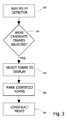
- Fig. 3 describing a method for displaying selected candidate image frames selected from an original image stream.
- polyp screening may be performed on a series of image frames included in an original image stream.
- polyp screening may be performed on a group of image frames selected from an original image stream.
- a group of image frames for polyp screening may be selected based on the location of interest, for example, polyp screening may be performed only on images captured in the colon. Other regions may be used for polyp screening.
- the polyp detector may be initiated and/or run to identify candidate image frames for polyp identification (block 320).
- a decision may be made as to which image frames to display (block 340).
- the decision may be based on the score assigned to each of the selected frames. For example, image frames assigned scores in a defined range may be selected for display. Other suitable methods for selecting frames for display may be implemented.
- identified forms may be marked (block 350), for example with an arrow pointing to the area, an enclosed shape encircling the area, or other suitable methods of marking an area in an image frame may be used.
- Selected image frames may be included in a subset image stream for display.
- a shortened movie for example a polyp screening movie
- the movie or streaming image frames may be shown or displayed to the health professional for diagnosis (block 370).
- the moving image stream may include a series of candidate image frames, typically still images, and may be displayed or stored as, for example, a subset image stream, a video, moving image, or movie. Other operations of series of operations may be used.
- Polyp screening and image selection may be performed in real time, or may be performed during the downloading procedure to the workstation 14 (Fig. 1), or at other suitable times or points in the imaging and/or screening procedure.
- FIG. 4A showing schematic screen of a graphical user interface (GUI) that may be used, according to one embodiment, to display a polyp screening movie including candidate image frames selected for polyp identification.
- the polyp screening movie may include image frames automatically selected by a polyp detector.
- Polyp screening movie window 410 may display a streaming display of image frames while an indicator 450 may advance to a position along a summarized graphical presentation bar 420 e.g. time/location bar that may indicate from where along the image stream the current frame displayed in movie window 410 may have been obtained.
- One or more image frames in movie window 410 may, for example, be marked to highlight areas in each frame that may potentially be a polyp form as may be described herein.
- a tracking curve 460 that may track the course of the imaging device may be shown.
- An indicator similar to indicator 450 may be used on the tracking curve to show correspondence with image frames displayed in window movie 410 and graphical presentation bar 420.
- Summarized graphical presentation bar 420 may be similar to summarized graphical presentation bar described for example in US Patent Application Publication Number 20050075551, published on April 7, 2005 which is assigned to the common assignee of the present application and incorporated herein by reference in its entirety or may be similar to other suitable graphical presentations.
- the position of indicator 450 along bar 420 may be controlled by user input to initiate image streaming in movie window 410 from a specified image frame in the image stream.
- Markers 470 may indicate from where along bar 420 candidate image frames may have been obtained.
- Control buttons 440 may be included in the GUI 400 and may allow a user to, for example, fast-forward, rewind, stop, play or reach the beginning or end of an image stream displayed in movie window 410.
- control buttons 440 may allow a user to choose to view image frames not selected as candidate image frames, for example, to view image frames that may appear in the original image frame directly before or after a candidate image frame.
- Polyp screening button 480 may allow a user to initiate the polyp screening procedure for example as described in Fig. 2 and Fig. 3 or to initiate streaming of the shortened polyp movie in movie window 410.
- the automatic polyp screening may be initiated automatically or at a different point in the overall diagnostic procedure, e.g. during recording, downloading, and/or uploading of image data.
- one or more image frames may be shown concurrently in movie window 410.
- a user or health professional may select one or more image frames from the movie window 410 to include in a report, e.g. diagnosis report.
- Markers 470 may be highlighted to indicate that a specific frame has been selected. Additional markers 470, marking non-candidate images may be added by the user.
- Clicking or otherwise indicating 'make report' button 490 may advance a user to a new screen that may show image frames that the user selected and provide a template for a user to prepare a diagnosis report.
- FIG. 4B showing an alternate schematic screen of a GUI used to display one or more selected image frames according to one embodiment of the invention.
- one or more image frames 411 selected by the polyp detector may be shown in screen 401, for example image frames 411 may be shown as thumbnails.
- the image frames 411 may include markings to locate polyps automatically detected by the polyp detector and/or detected by the health profession reviewing the images.
- Markers 470 may indicate from where along bar 420 selected image frames may have been obtained.
- each of the image frames may be indexed and used to identify corresponding markers 470.
- a scroll bar 445 may be used to scroll down and/or update screen 401 to show more image frames 411 when not all the image frames 411 selected by polyp detector fit on a single screen. Selecting an image frame 411 by user input, for example by pointing with a mouse and clicking may initiate display of the selected image frame in a large size for example, for the purpose of user inspection.
- a user or health professional may select one or more image frames from the selected frames 411 to include in a report and may add markings to the image frames. Indices 471 may be highlighted, colored or otherwise marked to show them as user selected images. One or more images frames 411 selected may be unselected. Choosing and/or clicking on make report button 490 may advance a user to a new screen that may show image frames that the user selected and may allow the user to prepare a diagnosis report or to prepare a referral to an additional diagnosis and/or treatment procedure.
- Polyps may be one example of a morphologic feature and/or abnormality that may be detected and used for diagnosis. In other embodiments the method described herein may be used to detect other morphologic features. It will be appreciated by persons skilled in the art that the present invention is not limited to what has been particularly shown and described herein. Rather the scope of the present invention is defined only by the claims, which follow:
Abstract
Description
- The present invention relates to an in-vivo imaging device, system, and method to screen for the presence of polyps along a body lumen.
- Polyps, abnormal growths or tumors that may project from a mucous membrane, for example the body lumen wall of the nose, gastrointestinal (GI) tract, and the uterus may be known to occur and in some cases may be an important precursor to cancer. Colorectal polyps found in the colon or rectum of the GI tract may be known to be a precursor for colorectal cancer. The known long pre-malignant stadium of colorectal cancer and the known high survival rate after polyp removal may enable efficient prevention of colorectal cancer by systematic screening and timely removal of colorectal polyps. Manual screening procedures or methods, for example, screening procedures to screen for colorectal polyps found in the colon or rectum are known.
- Manual polyp screening methods may include imaging a body lumen wall, for example, the entire length of the colon or the entire GI tract with a stream of image frames and manually reviewing the stream to detect and/or identify in one or more image frames showing any visible morphologic changes to the membrane of the body lumen wall.
- Devices and systems for performing in-vivo imaging, for example, of body lumen walls are known in the art. Such devices may include, inter alia, various endoscopic imaging systems, computed tomography (CT) devices, and x-ray imaging devices.
- Typically, the stream of image frames captured during a screening procedure, for example a colorectal polyps screening procedure may be lengthy so as to cover substantially the entire area of the colon and rectum. Manually reviewing all image frames may be tedious as well as undesirable and inefficient as a quick screening procedure to indicate the presence of polyps or to indicate the probability that polyps may be present in a body lumen. In addition, the visibility of a polyp may be subtle and a health professional may miss the occurrence of one or more polyps when reviewing a lengthy stream of image frames.
- Known polyp screening procedures typically require cleansing preparation and insufflation. Insufflation may stretch and flatten a polyp so that it may be difficult to detect a polyp. In addition, the cleansing preparation and insufflation may be unpleasant for the patient and may result in patients avoiding undergoing such a procedure.
- An embodiment of the system and method of the present invention may enable automatic screening of polyps along a body lumen. According to one embodiment of the present invention, at least one image frame, for example stream of image frames may be captured, for example, by an autonomous imaging device. The presence of a predetermined geometric form, for example a substantially elliptical form, visible in the captured stream of images may be automatically detected by a polyp detector and may be classified based on at least one predetermined parameter, for example based on the color, size, and/or shape of the identified form. Scores may be assigned to individual image frames based on the number of identified forms detected in each image frame and based on its classification. Candidate image frames may be selected based on the scoring and may be displayed to a user.
- Throughout the description and claims of this specification, the words "comprise" and "contain" and variations of the words, for example "comprising" and "comprises", means "including but not limited to", and is not intended to (and does not) exclude other moieties, additives, components, integers or steps.
- Throughout the description and claims of this specification, the singular encompasses the plural unless the context otherwise requires. In particular, where the indefinite article is used, the specification is to be understood as contemplating plurality as well as singularity, unless the context requires otherwise.
- Features, integers, characteristics, compounds, chemical moieties or groups described in conjunction with a particular aspect, embodiment or example of the invention are to be understood to be applicable to any other aspect, embodiment or example described herein unless incompatible therewith.
- The present invention will be understood and appreciated more fully from the following detailed description taken in conjunction with the drawings in which:
- Figure 1 shows schematic illustration of an in-vivo imaging system according to an embodiment of the present invention;
- Figure 2 is a flow chart describing a method for identifying potential polyp structures that may be visible in an image stream according to an embodiment of the present invention;
- Figure 3 is a flow chart describing a method for displaying selected image frames from an image stream according to embodiments of the present invention;
- Figure 4A shows a schematic graphical user interface (GUI) according to an embodiment of the present invention; and
- Figure 4B shows a schematic graphical user interface (GUI) according to an alternate embodiment of the present invention.
- It will be appreciated that for simplicity and clarity of illustration, elements shown in the figures have not necessarily been drawn accurately or to scale. For example, the dimensions of some of the elements may be exaggerated relative to other elements for clarity, or several physical components may be included in one functional block or element. Further, where considered appropriate, reference numerals may be repeated among the figures to indicate corresponding or analogous elements.
- In the following description, various aspects of the present invention will be described. For purposes of explanation, specific configurations and details are set forth in order to provide a thorough understanding of the present invention. However, it will also be apparent to one skilled in the art that the present invention may be practiced without the specific details presented herein. Furthermore, well-known features may be omitted or simplified in order not to obscure the present invention.
- The colorectal polyp may be an important precursor to colon cancer. This benign lesion typically may protrude from the wall as a small, sloped mound and may be seen in a two dimensional image as a circular or elliptical form. Other identifying features may be used to identify a polyp. The known long pre-malignant stadium and the known high survival rate after polyp removal may enable efficient prevention of colon cancer by systematic screening and timely removal of colorectal polyps.
- Embodiments of the present invention, describe a system, and method for screening for colorectal polyps, for example by providing a system, and method for automatically, without a user intervention, identifying, detecting, selecting, and marking image frames captured in the GI tract that may indicate the presence of colorectal poylps. The selected image frames may be displayed to a health professional for diganosis. According to one embodiment of the present invention, an autonomous in-vivo imaging device, for example an imaging device in the form of a swallowable capsule, may capture a series of image frames of a body lumen as well as other information from within or along a body lumen and may transmit the captured images and other information to one or more external units. Analysis of the transmitted data may be used to automatically and/or machine select and mark image frames that may be candidates for polyp identification. Analysis and processing of the data may be performed automatically without user intervention. Machine selection, detection and/or marking of image frames that may be candidates for polyp identification may be performed at least partially by a polyp detector and such that user intervention in the detection of image frames that may be candidates for polyp identification may not be required. Machine selection, detection an/or marking may be performed by, for example, one or more processors, a worksation, circuitry, a sensor or any other computation and/or sensing able device. Selected images may be displayed to a health professional for diagnosis. In some embodiments of the present invention, screening may also be facilitated with data that may be partially occluded by content. For example, image frames may be captured in an environment that may be partially occluded with content, for example content that may be present within a body lumen, e.g. colon.
- Reference is made to Fig. 1, which shows a schematic diagram of an in-vivo imaging system according to an embodiment of the present invention. Typically, the in-vivo imaging system may include an in-
vivo imaging device 40, an external receiving device and/orrecording device 12, e.g. data reciever, and aworkstation 14. The in-vivo imaging device 40 may have animager 46, for capturing image frames or a stream of image frames, anillumination source 42, for illuminating the body lumen, apower source 45 forpowering device 40, aprocessor 44 for processing data and commands to and fromdevice 40, and atransmitter 41 withantenna 47, for transmitting image and possibly other data to anexternal receiver 12. In some embodiments of the present invention, in-vivo device 40 may include one ormore sensors 30, in addition toimager 46, for example, temperature sensors, pH sensors, pressure sensors, blood sensors, tracking sensors, etc.Imager 46 may be a CCD or CMOS imager, or may be another solid state imaging device or other imaging device.Illumination source 42 may include one or more LEDs or other illumination sources. In some embodiments of the present invention,device 40 may be an autonomous device, a capsule, or a swallowable capsule. In other embodiments of the present invention,device 40 may not be autonomous, for example,device 40 may be an endoscope or other in-vivo imaging device. - The in-
vivo imaging device 40 may typically, according an embodiment of the present invention, transmit information (e.g., images or other data) to anexternal receiver 12 possibly close to or worn on a subject. Typically, thereceiver 12 may include an antenna orantenna array 15 and a datareceiver storage unit 16. Typicallyantenna array 15 may pick up signals transmitted bydevice 40 or thetransmitter 41 andantenna 47 ofdevice 40. Theexternal receiver 12 may include one ormore processors 17 for processing image data or other data.Receiver 12 may include a tracking unit 11, for tracking the location of an autonomous in-vivo imaging device 40 over time. For example, tracking unit 11 may track the location ofdevice 40 in three dimensional space over time and/or may track the distance, for example the distance over time thatdevice 40 traveled through the GI tract or through a specific organ in the GI tract over time. Tracking unit 11 may be similar to various embodiments described, for example, in US Patent Application Publication No.US-2002-0173718-A1 published on November 21, 2002 andUS Patent Application No. 10/879,053 filed on June 30, 2004 device 40. Thereceiver 12 may take on other suitable configurations and may not include an antenna or antenna array. In one embodiment of the present invention, thereceiver 12 may, for example, include a LCD display for displaying image data or other data, e.g. tracking data. In other embodiments,receiver 12 may be electrically connected, e.g. via wire, blue tooth, or wireless connection, to a display unit,e.g. display unit 18 orworkstation 14, to display data transmitted by in-vivo device 40 and/or processed by processingunit workstation 14. - In one embodiment of the present invention, the
receiver 12 may, for example, receive and store data fromimaging device 40, e.g. an image stream data captured and/or processed byprocessor 17 and later transfer the received data to aworkstation 14, such as a personal computer, laptop or other portable or stationary computing devices, where the data may be further analyzed, stored, and/or displayed to a user, e.g. a health professional. Typically,workstation 14 may include processingunit 13, dataprocessor storage unit 19, a disk drive, input-output devices, anddisplay unit 18 e.g. a monitor, although alternate configurations are possible. Processingunit 13 may typically, as part of its functionality, act as a controller controlling the display of data for example, image data or other data. In one example,processor 13 and/orprocessor 17 may be employed to construct a polyp screening movie from candidate image frames selected by the poly detector.Display unit 18 may typically be a conventional video display, but may, in addition, be any other device capable of providing image or other data. Instructions or software for carrying out a method according to an embodiment of the invention may be included as part ofworkstation 14, for example stored inmemory 19. A polyp detector may be included as part of the functionality ofprocessor 13,processor 44 and/orprocessor 17 and may select from an image stream, one or more image frames that may be candidates for polyp identification. In another embodiment, poly detector may be included as part of the functionality of the solid state imaging device,e.g. imager 40. In yet another embodiment, polyp detector may be included as part of the functionality of an ASIC (application specific integrated circuit), for example and ASIC included indevice 40. In one example, the polyp detector may be a series of commands or an algorithm that may be implemented to detect in one or more image frames, for example a stream of image frames, the presence of predetermined features and/or parameters. Based on the detection, candidate image frames may be selected. Output from the polyp detector may be transferred to adisplay unit 18, a display unit included inreceiver 12 and/orprocessing unit - In other embodiments, each of the various components need not be required; for example, the in-
vivo device 40 may transmit or otherwise transfer (e.g., by wire) data marking image frames that may be candidates for polyp identification directly to a viewing device orworkstation 14. In one embodiment of the present invention,device 40 may only transmit selected image frames that may be candidates for polyp identification. - In-vivo imaging systems suitable for use with embodiments of the present invention may be similar to various embodiments described, for example in
US Patent No. 5,604,531 , entitled "In-Vivo Video Camera System", assigned to the common assignee of the present application and incorporated herein by reference in its entirety, and/orUS Patent Application Publication Number 20010035902 published on November 1, 2001 and entitled "Device and System for In-Vivo Imaging", also assigned to the common assignee of the present application and incorporated herein by reference in its entirety. - Other in-vivo systems, having other configurations, may be used. Of course, devices, systems, structures, functionalities and methods as described herein may have other configurations, sets of components, processes, etc.
- In some embodiments of the present invention, an in-
vivo image device 40 may be swallowed, or otherwise inserted within a gastrointestinal (GI) tract and may pass through the GI tract, for example, via natural peristaltic motion while capturing a series of image frames, e.g. capturing image frames periodically at two frames per second. In other embodiments of the present invention, the in-vivo imaging device may advance through the GI tract via other suitable means and may capture image frames at other suitable rates, for example, at variable rates. Image frames captured as well as other data may be transmitted externally for processing and display. According to one embodiment of the present invention, tracking data, tracking the location of the in-vivo imaging device over time or over the course through the GI tract may be included in the processing and display of data. For example, tracking data may be used to indicate the point, e.g. the image frame, at which polyp screening should begin, e.g. the tracking system may detect entrance into the colon. Data captured may be processed to automatically select image frames that may be candidates for polyp diagnosis. - According to an embodiment of the present invention, the screening procedure with
device 40 may be performed without previously requiring a patient to undergo a cleansing preparation that may be common in known colonoscopy procedures or other procedures. In some instances, images captured bydevice 40 may include content present in the body lumen that may partially occlude imaging along the body lumen walls. - Reference is now made to Fig. 2 describing a method for automatic selection of image frames that may be candidates for polyp identification. Selection may be based on automatic detection of one or more geometric forms that may be polyp structures in an image frame. For example, colorectal polyps may appear in a two dimensional image as a substantially circular or elliptical shaped form. Other known morphologic features that may also appear as substantially elliptical forms in a two dimensional image may include, for example, content, or bubbles present within a body lumen. In one embodiment of the present invention a polyp detector may search for substantially elliptical forms in an image frame and classify the forms based on at least one predetermined and/or predefined parameter, for example shape, size and/or color. For example, a polyp detector may search for substantially elliptical forms in an image frame and classify the forms as either tissue, e.g. polyp or as another form, e.g. content based on their shape, size and/or color. Other suitable predetermined and/or predefined geometrical forms may be detected and/or identified and other parameters for classifying the forms may be used. In one example, polyp screening may be performed on each of the individual image frames of the original image stream. In another embodiment, known motion tracking methods may be used to combine one or more image frames that may show overlapping regions and polyp screening may be performed on the combined images.
- According to one embodiment of the present invention, an image frame, for example an image frame captured by an in-
vivo imaging device 40 along a body lumen may be selected (block 205). In one example, polyp screening may begin on the first image frame captured by the in-vivo device or the first image frame in the original image stream. In an alternate example, polyp screening may begin on the first image frame captured in a specific region of interest, for example polyp screening may be performed starting with the first image captured in the cecum, or colon. Position tracking methods, image analysis or data from various sensors may be used to identify the relevant image frame to be used or analyzed in the screening procedure. Other methods may be used. A gradient map of the selected frame may be generated (block 210) by methods known in the art, for example, by implementing known Sobel or Canny filters. The generated gradient map may be used to identify, for example automatically identify without user intervention, the presence of one or more forms or structures that may have a substantially elliptical shape (block 220). For example, a Hough transform may be used to identify a substantially elliptical shape. Other suitable methods may be used to identify an elliptical structure. Typically elliptical shaped forms in the colon and rectum may have a high probability of being either content or a polyp. Parameters, such as dimensions and/or size of each form as well as the color may be used to differentiate between forms that may be content, polyps, or neither. Identified ellipses and/or other forms may be classified and/or sorted, for example, as either content or a polyp based on analysis of, for example, their size and color (block 230). For example identified forms may be sorted based on comparing the color of the forms to defined colors. - In one example, tissue color may be defined based on sample images taken, for example, by a pool or database of images taken from volunteers. In another example, tissue color may be defined per patient based on color in one or more areas in an image frame and/or in one or more image frames. For example an area in an image frame identified as not having an elliptical from may be used to define a typical or average tissue color. Tissue color may, for example, be defined as one color or may be defined as a range of colors. In one example, average or typical tissue color may be defined as a varying parameter that may change, for example, in a defined way over the length of the GI tract, or over the length of a specific section in the GI tract, e.g. the colon. Content color may be defined in a similar manner. In one example, content color may be defined based on sample images taken, for example, from a database of images captured in one or more volunteers. In another example, content color may be defined per patient. Content color may, for example, be defined as one color or may be defined as a range of colors. In one example, average or typical content color may be defined as a varying parameter that may change, for example, in a defined way over the length of the GI tract, or over the length of a specific section in the GI tract, e.g. the colon. In another example, the user, e.g. the health professional may, for example, mark areas in one or more image frames that may be used as reference tissue color and/or reference content colors. Other suitable methods of determining reference colors of tissue and content may be used. The identified elliptical forms may be compared to the defined tissue color and to the defined content color. In other examples the elliptical forms may be compared to other defined colors or to other colors. Color and size sorting may be based the probability that each ellipse identified is content, polyp, or neither. For example, if an identified elliptical area has a probability higher than a first threshold that it may be a polyp and has a probability lower than another threshold that it may be content; that identified elliptical area may be selected for the polyp category. In other examples, color or other identifying features to identify or classify a geometrical form as a bubble may be defined. Other suitable methods may be used for sorting defined forms.
- In
block 240 ellipses classified as tissue maybe marked. In block 250 a score may be assigned to the frame based on the classifying. For example a score may be assigned to an image frame based on the number of forms categorized and/or classified as polyps in the image frame and the probability, for example the overall probability, that a polyp may have been correctly identified in the image frame. The classifying may be based on parameters such as color, size, and/or shape. Based on the score allotted, candidate image frames for polyp diagnosis may be selected (block 260). In one example, an image frame allotted a score above a defined threshold, may be marked as an image frame that may be a candidate for polyp diagnosis. Other image frames, e.g. subsequent image frames, may undergo screening in the similar manner described herein. Other operations or series of operations may be used. - In one embodiment of the present invention, a polyp detector may automatically select from an original image stream one or more candidate image frames for polyp diagnosis and a display unit may display the selected image frames for diagnosis by a health care professional. Reference is now made to Fig. 3 describing a method for displaying selected candidate image frames selected from an original image stream. In one embodiment of the present invention, polyp screening may be performed on a series of image frames included in an original image stream. In other embodiments, polyp screening may be performed on a group of image frames selected from an original image stream. In one example, a group of image frames for polyp screening may be selected based on the location of interest, for example, polyp screening may be performed only on images captured in the colon. Other regions may be used for polyp screening. The polyp detector may be initiated and/or run to identify candidate image frames for polyp identification (block 320). In cases where candidate image frames were selected (block 330) a decision may be made as to which image frames to display (block 340). In one example, the decision may be based on the score assigned to each of the selected frames. For example, image frames assigned scores in a defined range may be selected for display. Other suitable methods for selecting frames for display may be implemented. In some embodiments of the present invention, identified forms may be marked (block 350), for example with an arrow pointing to the area, an enclosed shape encircling the area, or other suitable methods of marking an area in an image frame may be used. Selected image frames may be included in a subset image stream for display. In block 360 a shortened movie, for example a polyp screening movie, may be constructed based on the subset image frame. The movie or streaming image frames may be shown or displayed to the health professional for diagnosis (block 370). The moving image stream may include a series of candidate image frames, typically still images, and may be displayed or stored as, for example, a subset image stream, a video, moving image, or movie. Other operations of series of operations may be used. Polyp screening and image selection may be performed in real time, or may be performed during the downloading procedure to the workstation 14 (Fig. 1), or at other suitable times or points in the imaging and/or screening procedure.
- Reference is now made to Figure 4A showing schematic screen of a graphical user interface (GUI) that may be used, according to one embodiment, to display a polyp screening movie including candidate image frames selected for polyp identification. The polyp screening movie may include image frames automatically selected by a polyp detector. Polyp
screening movie window 410 may display a streaming display of image frames while anindicator 450 may advance to a position along a summarizedgraphical presentation bar 420 e.g. time/location bar that may indicate from where along the image stream the current frame displayed inmovie window 410 may have been obtained. One or more image frames inmovie window 410 may, for example, be marked to highlight areas in each frame that may potentially be a polyp form as may be described herein. Atracking curve 460 that may track the course of the imaging device may be shown. An indicator similar toindicator 450 may be used on the tracking curve to show correspondence with image frames displayed inwindow movie 410 andgraphical presentation bar 420. - Summarized
graphical presentation bar 420 may be similar to summarized graphical presentation bar described for example inUS Patent Application Publication Number 20050075551, published on April 7, 2005 which is assigned to the common assignee of the present application and incorporated herein by reference in its entirety or may be similar to other suitable graphical presentations. The position ofindicator 450 alongbar 420 may be controlled by user input to initiate image streaming inmovie window 410 from a specified image frame in the image stream.Markers 470 may indicate from where alongbar 420 candidate image frames may have been obtained.Control buttons 440 may be included in theGUI 400 and may allow a user to, for example, fast-forward, rewind, stop, play or reach the beginning or end of an image stream displayed inmovie window 410. In one embodiment of the present invention,control buttons 440 may allow a user to choose to view image frames not selected as candidate image frames, for example, to view image frames that may appear in the original image frame directly before or after a candidate image frame.Polyp screening button 480 may allow a user to initiate the polyp screening procedure for example as described in Fig. 2 and Fig. 3 or to initiate streaming of the shortened polyp movie inmovie window 410. In other examples, the automatic polyp screening may be initiated automatically or at a different point in the overall diagnostic procedure, e.g. during recording, downloading, and/or uploading of image data. In other embodiments of the present invention, one or more image frames may be shown concurrently inmovie window 410. - A user or health professional may select one or more image frames from the
movie window 410 to include in a report, e.g. diagnosis report.Markers 470 may be highlighted to indicate that a specific frame has been selected.Additional markers 470, marking non-candidate images may be added by the user. Clicking or otherwise indicating 'make report'button 490 may advance a user to a new screen that may show image frames that the user selected and provide a template for a user to prepare a diagnosis report. - Reference is now made to Figure 4B showing an alternate schematic screen of a GUI used to display one or more selected image frames according to one embodiment of the invention. In one embodiment of the present invention, one or more image frames 411 selected by the polyp detector may be shown in
screen 401, for example image frames 411 may be shown as thumbnails. The image frames 411 may include markings to locate polyps automatically detected by the polyp detector and/or detected by the health profession reviewing the images.Markers 470 may indicate from where alongbar 420 selected image frames may have been obtained. In one example, each of the image frames may be indexed and used to identify correspondingmarkers 470. Ascroll bar 445 may be used to scroll down and/orupdate screen 401 to show more image frames 411 when not all the image frames 411 selected by polyp detector fit on a single screen. Selecting animage frame 411 by user input, for example by pointing with a mouse and clicking may initiate display of the selected image frame in a large size for example, for the purpose of user inspection. A user or health professional may select one or more image frames from the selectedframes 411 to include in a report and may add markings to the image frames.Indices 471 may be highlighted, colored or otherwise marked to show them as user selected images. One or more images frames 411 selected may be unselected. Choosing and/or clicking onmake report button 490 may advance a user to a new screen that may show image frames that the user selected and may allow the user to prepare a diagnosis report or to prepare a referral to an additional diagnosis and/or treatment procedure. - Polyps may be one example of a morphologic feature and/or abnormality that may be detected and used for diagnosis. In other embodiments the method described herein may be used to detect other morphologic features. It will be appreciated by persons skilled in the art that the present invention is not limited to what has been particularly shown and described herein. Rather the scope of the present invention is defined only by the claims, which follow:
Claims (12)
- A system to automatically screen for the presence of a polyp along a body lumen comprising:an imaging device to provide a stream of images of the body lumen;a polyp detector to identify a geometric form in at least one image frame of the image stream and to classify the form; anda display unit to display the at least one image frame.
- The system according to claim 1 wherein the geometric form is an elliptical shaped form.
- The system according to claim 1 or 2 wherein the polyp detector is to classify the geometric form by its color.
- The system according to claim 1 or 2 where in the polyp detector is to generate a gradient map of the at least one image frame.
- The system according to claim 1 or 2 wherein the polyp detector is to automatically select from the image stream candidate image frames including the geometric form.
- The system according to claim 5 comprising a processing unit wherein the processing unit is to construct a polyp screening movie from the candidate image frames selected by the polyp detector.
- The system according to claim 5 or 6 wherein the display unit is to display candidate image frames selected by the polyp detector.
- The system according to any preceding claim wherein the polyp detector is included in the imaging device.
- The system according to any one of claims 1 to 7 wherein the polyp detector is included in an external receiving device wherein the external receiving device is to receive data from the imaging device.
- The system according to any preceding claim wherein the display unit is to display the at least one image frame if the polyp detector identifies the geometric form in the at least one image frame and classifies the form according to a preselected criteria.
- The system according to any preceding claim wherein the imaging device is an autonomous in-vivo device in the form of a swallowable capsule.
- The system according to claim 11 comprising a tracking unit wherein the tracking unit is to track a location of the autonomous in-vivo imaging device within the body lumen.
Applications Claiming Priority (1)
| Application Number | Priority Date | Filing Date | Title |
|---|---|---|---|
| US11/239,392 US8423123B2 (en) | 2005-09-30 | 2005-09-30 | System and method for in-vivo feature detection |
Publications (3)
| Publication Number | Publication Date |
|---|---|
| EP1769729A2 true EP1769729A2 (en) | 2007-04-04 |
| EP1769729A3 EP1769729A3 (en) | 2007-05-02 |
| EP1769729B1 EP1769729B1 (en) | 2012-04-18 |
Family
ID=37685037
Family Applications (1)
| Application Number | Title | Priority Date | Filing Date |
|---|---|---|---|
| EP06121330A Active EP1769729B1 (en) | 2005-09-30 | 2006-09-27 | System and method for in-vivo feature detection |
Country Status (4)
| Country | Link |
|---|---|
| US (1) | US8423123B2 (en) |
| EP (1) | EP1769729B1 (en) |
| JP (1) | JP5280620B2 (en) |
| AT (1) | ATE553691T1 (en) |
Cited By (1)
| Publication number | Priority date | Publication date | Assignee | Title |
|---|---|---|---|---|
| CN102934127A (en) * | 2010-04-28 | 2013-02-13 | 基文影像公司 | System and method for displaying portions of in-vivo images |
Families Citing this family (51)
| Publication number | Priority date | Publication date | Assignee | Title |
|---|---|---|---|---|
| US7474327B2 (en) | 2002-02-12 | 2009-01-06 | Given Imaging Ltd. | System and method for displaying an image stream |
| US8565372B2 (en) | 2003-11-26 | 2013-10-22 | Hologic, Inc | System and method for low dose tomosynthesis |
| US7123684B2 (en) | 2002-11-27 | 2006-10-17 | Hologic, Inc. | Full field mammography with tissue exposure control, tomosynthesis, and dynamic field of view processing |
| US10638994B2 (en) | 2002-11-27 | 2020-05-05 | Hologic, Inc. | X-ray mammography with tomosynthesis |
| US7577282B2 (en) | 2002-11-27 | 2009-08-18 | Hologic, Inc. | Image handling and display in X-ray mammography and tomosynthesis |
| US7616801B2 (en) | 2002-11-27 | 2009-11-10 | Hologic, Inc. | Image handling and display in x-ray mammography and tomosynthesis |
| EP3106094B1 (en) | 2004-11-26 | 2021-09-08 | Hologic, Inc. | Integrated multi-mode mammography/tomosynthesis x-ray system |
| JP4914634B2 (en) * | 2006-04-19 | 2012-04-11 | オリンパスメディカルシステムズ株式会社 | Capsule medical device |
| JP5113841B2 (en) * | 2006-08-21 | 2013-01-09 | エスティーアイ・メディカル・システムズ・エルエルシー | Computer-aided analysis using video from an endoscope |
| US8588887B2 (en) | 2006-09-06 | 2013-11-19 | Innurvation, Inc. | Ingestible low power sensor device and system for communicating with same |
| WO2008030482A2 (en) | 2006-09-06 | 2008-03-13 | Innurvation Inc | System and method for acoustic information exchange involving an ingestible low power capsule |
| EP2063780B1 (en) * | 2006-09-06 | 2018-04-11 | Innurvation, Inc. | Imaging and locating systems and methods for a swallowable sensor device |
| US20090088618A1 (en) | 2007-10-01 | 2009-04-02 | Arneson Michael R | System and Method for Manufacturing a Swallowable Sensor Device |
| US7871403B2 (en) * | 2008-02-26 | 2011-01-18 | Olympus Medical Systems Corp. | Medical support control system |
| US8529441B2 (en) | 2008-02-12 | 2013-09-10 | Innurvation, Inc. | Ingestible endoscopic optical scanning device |
| US20100016662A1 (en) * | 2008-02-21 | 2010-01-21 | Innurvation, Inc. | Radial Scanner Imaging System |
| WO2010005571A2 (en) * | 2008-07-09 | 2010-01-14 | Innurvation, Inc. | Displaying image data from a scanner capsule |
| US8647259B2 (en) | 2010-03-26 | 2014-02-11 | Innurvation, Inc. | Ultrasound scanning capsule endoscope (USCE) |
| EP2452622A1 (en) * | 2010-11-11 | 2012-05-16 | Philips Intellectual Property & Standards GmbH | Colon screening by using magnetic particle imaging |
| JP2012170751A (en) * | 2011-02-23 | 2012-09-10 | Olympus Medical Systems Corp | Image display device, method and program, and capsule type endoscope system |
| US8873816B1 (en) * | 2011-04-06 | 2014-10-28 | Given Imaging Ltd. | Method and system for identification of red colored pathologies in vivo |
| US8929629B1 (en) | 2011-06-29 | 2015-01-06 | Given Imaging Ltd. | Method and system for image-based ulcer detection |
| US8861783B1 (en) | 2011-12-30 | 2014-10-14 | Given Imaging Ltd. | System and method for detection of content in an image stream of the gastrointestinal tract |
| US8923585B1 (en) | 2012-01-31 | 2014-12-30 | Given Imaging Ltd. | Method and system for image-based ulcer detection |
| US9854958B1 (en) * | 2013-03-23 | 2018-01-02 | Garini Technologies Corporation | System and method for automatic processing of images from an autonomous endoscopic capsule |
| US9324145B1 (en) * | 2013-08-08 | 2016-04-26 | Given Imaging Ltd. | System and method for detection of transitions in an image stream of the gastrointestinal tract |
| US9430706B1 (en) | 2013-10-02 | 2016-08-30 | Given Imaging Ltd. | System and method for detection of in-vivo pathology sequences |
| WO2015087332A2 (en) | 2013-12-11 | 2015-06-18 | Given Imaging Ltd. | System and method for controlling the display of an image stream |
| US9342881B1 (en) | 2013-12-31 | 2016-05-17 | Given Imaging Ltd. | System and method for automatic detection of in vivo polyps in video sequences |
| US10117563B2 (en) * | 2014-01-09 | 2018-11-06 | Gyrus Acmi, Inc. | Polyp detection from an image |
| WO2017027475A1 (en) * | 2015-08-07 | 2017-02-16 | Jianming Liang | Methods, systems, and media for simultaneously monitoring colonoscopic video quality and detecting polyps in colonoscopy |
| JP6704933B2 (en) | 2015-11-26 | 2020-06-03 | オリンパス株式会社 | Image processing apparatus, image processing method and program |
| EP3445247B1 (en) | 2016-04-22 | 2021-03-10 | Hologic, Inc. | Tomosynthesis with shifting focal spot x-ray system using an addressable array |
| DE112016006913T5 (en) * | 2016-05-27 | 2019-02-14 | Olympus Corporation | Image processing apparatus, operating method of the image processing apparatus, and operation program of the image processing apparatus |
| EP3267394A1 (en) * | 2016-07-04 | 2018-01-10 | Centre National De La Recherche Scientifique | Method and apparatus for real-time detection of polyps in optical colonoscopy |
| JP6326178B1 (en) * | 2016-07-05 | 2018-05-16 | オリンパス株式会社 | Image processing apparatus, image processing system, operation method of image processing apparatus, and operation program for image processing apparatus |
| US10806334B2 (en) * | 2017-02-28 | 2020-10-20 | Verily Life Sciences Llc | System and method for multiclass classification of images using a programmable light source |
| JP6751815B2 (en) * | 2017-04-28 | 2020-09-09 | オリンパス株式会社 | How to operate the endoscopic diagnosis support system, endoscopic diagnosis support program, and endoscopic diagnosis support system |
| WO2019008942A1 (en) | 2017-07-03 | 2019-01-10 | 富士フイルム株式会社 | Medical image processing device, endoscope device, diagnostic support device, medical service support device and report generation support device |
| WO2019008941A1 (en) | 2017-07-03 | 2019-01-10 | 富士フイルム株式会社 | Medical image processing device, endoscope device, diagnostic support device, medical service support device, and report generation support device |
| EP4129188A1 (en) | 2017-08-16 | 2023-02-08 | Hologic, Inc. | Techniques for breast imaging patient motion artifact compensation |
| EP3449835B1 (en) | 2017-08-22 | 2023-01-11 | Hologic, Inc. | Computed tomography system and method for imaging multiple anatomical targets |
| JP6797858B2 (en) * | 2018-04-18 | 2020-12-09 | キヤノン株式会社 | Medical image display device, display control device and display control method, program |
| CN112672709A (en) | 2018-07-31 | 2021-04-16 | 直观外科手术操作公司 | System and method for tracking the position of a robotically-manipulated surgical instrument |
| US11090017B2 (en) | 2018-09-13 | 2021-08-17 | Hologic, Inc. | Generating synthesized projection images for 3D breast tomosynthesis or multi-mode x-ray breast imaging |
| JP2022505154A (en) | 2018-10-19 | 2022-01-14 | ギブン イメージング リミテッド | Systems and methods for generating and displaying in-vivo image stream scrutiny information |
| KR20220010511A (en) * | 2019-05-17 | 2022-01-25 | 기븐 이미징 리미티드 | Systems, devices, apps, and methods for capsule endoscopic procedures |
| EP3832689A3 (en) | 2019-12-05 | 2021-08-11 | Hologic, Inc. | Systems and methods for improved x-ray tube life |
| US11471118B2 (en) | 2020-03-27 | 2022-10-18 | Hologic, Inc. | System and method for tracking x-ray tube focal spot position |
| US11786191B2 (en) | 2021-05-17 | 2023-10-17 | Hologic, Inc. | Contrast-enhanced tomosynthesis with a copper filter |
| WO2023153069A1 (en) * | 2022-02-09 | 2023-08-17 | 富士フイルム株式会社 | Medical image device, endoscope system, and medical certificate creation system |
Citations (4)
| Publication number | Priority date | Publication date | Assignee | Title |
|---|---|---|---|---|
| US5604531A (en) | 1994-01-17 | 1997-02-18 | State Of Israel, Ministry Of Defense, Armament Development Authority | In vivo video camera system |
| US20010035902A1 (en) | 2000-03-08 | 2001-11-01 | Iddan Gavriel J. | Device and system for in vivo imaging |
| US20020173718A1 (en) | 2001-05-20 | 2002-11-21 | Mordechai Frisch | Array system and method for locating an in vivo signal source |
| US20050075551A1 (en) | 2003-10-02 | 2005-04-07 | Eli Horn | System and method for presentation of data streams |
Family Cites Families (52)
| Publication number | Priority date | Publication date | Assignee | Title |
|---|---|---|---|---|
| US3683389A (en) * | 1971-01-20 | 1972-08-08 | Corning Glass Works | Omnidirectional loop antenna array |
| US3971362A (en) * | 1972-10-27 | 1976-07-27 | The United States Of America As Represented By The Administrator Of The National Aeronautics And Space Administration | Miniature ingestible telemeter devices to measure deep-body temperature |
| US3888237A (en) * | 1973-10-15 | 1975-06-10 | Olympus Optical Co | Ph-measuring device used in an endoscope |
| JPS5519124A (en) * | 1978-07-27 | 1980-02-09 | Olympus Optical Co | Camera system for medical treatment |
| JPS5745833A (en) | 1980-09-01 | 1982-03-16 | Taeko Nakagawa | Stomack camera |
| US6010453A (en) * | 1982-03-22 | 2000-01-04 | Instrumentarium Corporation | Tonometric catheter combination |
| DE3440177A1 (en) | 1984-11-02 | 1986-05-15 | Friedrich Dipl.-Ing. 8031 Eichenau Hilliges | Television recording and replay device for endoscopy on human and animal bodies |
| US4689621A (en) * | 1986-03-31 | 1987-08-25 | The United States Of America As Represented By The Administrator Of The National Aeronautics And Space Administration | Temperature responsive transmitter |
| JPH0664243B2 (en) * | 1986-04-30 | 1994-08-22 | オリンパス光学工業株式会社 | Endoscope |
| US4844076A (en) * | 1988-08-26 | 1989-07-04 | The Johns Hopkins University | Ingestible size continuously transmitting temperature monitoring pill |
| US4915113A (en) * | 1988-12-16 | 1990-04-10 | Bio-Vascular, Inc. | Method and apparatus for monitoring the patency of vascular grafts |
| US5421337A (en) * | 1989-04-14 | 1995-06-06 | Massachusetts Institute Of Technology | Spectral diagnosis of diseased tissue |
| JP2579372B2 (en) | 1989-12-04 | 1997-02-05 | 日本テキサス・インスツルメンツ株式会社 | Low power imaging device |
| JPH04109927A (en) | 1990-08-31 | 1992-04-10 | Toshiba Corp | Electronic endoscope apparatus |
| JP2948900B2 (en) | 1990-11-16 | 1999-09-13 | オリンパス光学工業株式会社 | Medical capsule |
| JP2768029B2 (en) | 1991-02-19 | 1998-06-25 | 日新電機株式会社 | Digestive system diagnostic device |
| US5279607A (en) * | 1991-05-30 | 1994-01-18 | The State University Of New York | Telemetry capsule and process |
| JP3285235B2 (en) | 1992-11-05 | 2002-05-27 | オリンパス光学工業株式会社 | Capsule device for in vivo observation |
| US5819736A (en) * | 1994-03-24 | 1998-10-13 | Sightline Technologies Ltd. | Viewing method and apparatus particularly useful for viewing the interior of the large intestine |
| WO1996016600A1 (en) * | 1994-11-30 | 1996-06-06 | Boston Scientific Corporation | Acoustic imaging and doppler catheters and guidewires |
| US5833603A (en) * | 1996-03-13 | 1998-11-10 | Lipomatrix, Inc. | Implantable biosensing transponder |
| US5853005A (en) * | 1996-05-02 | 1998-12-29 | The United States Of America As Represented By The Secretary Of The Army | Acoustic monitoring system |
| GB9619470D0 (en) | 1996-09-18 | 1996-10-30 | Univ London | Imaging apparatus |
| EP0908137A1 (en) * | 1997-10-06 | 1999-04-14 | Technologiestichting STW | A method and apparatus for making an image of a lumen or other body cavity and its surrounding tissue |
| US6240312B1 (en) * | 1997-10-23 | 2001-05-29 | Robert R. Alfano | Remote-controllable, micro-scale device for use in in vivo medical diagnosis and/or treatment |
| AU1927399A (en) * | 1998-01-16 | 1999-08-02 | Lumend, Inc. | Catheter apparatus for treating arterial occlusions |
| US8636648B2 (en) * | 1999-03-01 | 2014-01-28 | West View Research, Llc | Endoscopic smart probe |
| US6285897B1 (en) * | 1999-04-07 | 2001-09-04 | Endonetics, Inc. | Remote physiological monitoring system |
| JP4180736B2 (en) | 1999-05-28 | 2008-11-12 | マスプロ電工株式会社 | Joint reception equipment |
| JP3289779B2 (en) | 1999-07-30 | 2002-06-10 | 日本軽金属株式会社 | Method for producing hollow panel structure and hollow extruded profile for the production |
| GB2352636B (en) | 1999-08-03 | 2003-05-14 | Univ College London Hospitals | Improved passage-travelling device |
| IL134017A (en) | 2000-01-13 | 2008-04-13 | Capsule View Inc | Camera for viewing inside intestines |
| AU2001227020A1 (en) | 2000-01-19 | 2001-07-31 | Given Imaging Ltd. | A system for detecting substances |
| US7039453B2 (en) | 2000-02-08 | 2006-05-02 | Tarun Mullick | Miniature ingestible capsule |
| JP2001224553A (en) | 2000-02-17 | 2001-08-21 | Asahi Optical Co Ltd | Imaging instrument for capusle endoscope |
| US6947784B2 (en) * | 2000-04-07 | 2005-09-20 | The General Hospital Corporation | System for digital bowel subtraction and polyp detection and related techniques |
| US6709387B1 (en) | 2000-05-15 | 2004-03-23 | Given Imaging Ltd. | System and method for controlling in vivo camera capture and display rate |
| US6475145B1 (en) * | 2000-05-17 | 2002-11-05 | Baymar, Inc. | Method and apparatus for detection of acid reflux |
| KR100741999B1 (en) * | 2000-09-27 | 2007-07-23 | 기븐 이미징 리미티드 | An immobilizable in vivo monitoring system and its method |
| IL157892A0 (en) * | 2001-03-14 | 2004-03-28 | Given Imaging Ltd | Method and system for detecting colorimetric abnormalities |
| US6549796B2 (en) * | 2001-05-25 | 2003-04-15 | Lifescan, Inc. | Monitoring analyte concentration using minimally invasive devices |
| US7161164B2 (en) * | 2001-07-05 | 2007-01-09 | Given Imaging Ltd. | Device and method for attenuating radiation from in vivo electrical devices |
| JP4109927B2 (en) | 2002-08-20 | 2008-07-02 | セイコークロック株式会社 | Radio correction watch and method |
| WO2004058041A2 (en) | 2002-12-26 | 2004-07-15 | Given Imaging Ltd. | Immobilizable in vivo sensing device |
| US7480401B2 (en) * | 2003-06-23 | 2009-01-20 | Siemens Medical Solutions Usa, Inc. | Method for local surface smoothing with application to chest wall nodule segmentation in lung CT data |
| DE10346276B4 (en) * | 2003-10-06 | 2007-01-18 | Siemens Ag | System for the automated localization of lesions in the gastrointestinal tract for therapy with laser light of an endorobot |
| US7454045B2 (en) * | 2003-10-10 | 2008-11-18 | The United States Of America As Represented By The Department Of Health And Human Services | Determination of feature boundaries in a digital representation of an anatomical structure |
| US8164672B2 (en) * | 2003-12-31 | 2012-04-24 | Given Imaging Ltd. | System and method for displaying an image stream |
| CA2631564A1 (en) * | 2004-11-29 | 2006-06-01 | Hypermed, Inc. | Medical hyperspectral imaging for evaluation of tissue and tumor |
| EP2319406A1 (en) * | 2004-12-28 | 2011-05-11 | Hyperspectral Imaging, Inc | Hyperspectral/multispectral imaging in determination, assessment and monitoring of systemic physiology and shock |
| JP5015515B2 (en) | 2006-08-02 | 2012-08-29 | 伊藤超短波株式会社 | Muscle training equipment |
| JP2009240621A (en) * | 2008-03-31 | 2009-10-22 | Hoya Corp | Endoscope apparatus |
-
2005
- 2005-09-30 US US11/239,392 patent/US8423123B2/en active Active
-
2006
- 2006-09-27 EP EP06121330A patent/EP1769729B1/en active Active
- 2006-09-27 AT AT06121330T patent/ATE553691T1/en active
- 2006-09-29 JP JP2006269535A patent/JP5280620B2/en active Active
Patent Citations (4)
| Publication number | Priority date | Publication date | Assignee | Title |
|---|---|---|---|---|
| US5604531A (en) | 1994-01-17 | 1997-02-18 | State Of Israel, Ministry Of Defense, Armament Development Authority | In vivo video camera system |
| US20010035902A1 (en) | 2000-03-08 | 2001-11-01 | Iddan Gavriel J. | Device and system for in vivo imaging |
| US20020173718A1 (en) | 2001-05-20 | 2002-11-21 | Mordechai Frisch | Array system and method for locating an in vivo signal source |
| US20050075551A1 (en) | 2003-10-02 | 2005-04-07 | Eli Horn | System and method for presentation of data streams |
Cited By (2)
| Publication number | Priority date | Publication date | Assignee | Title |
|---|---|---|---|---|
| CN102934127A (en) * | 2010-04-28 | 2013-02-13 | 基文影像公司 | System and method for displaying portions of in-vivo images |
| CN102934127B (en) * | 2010-04-28 | 2016-11-16 | 基文影像公司 | The system and method for image section in display body |
Also Published As
| Publication number | Publication date |
|---|---|
| US20070078335A1 (en) | 2007-04-05 |
| EP1769729B1 (en) | 2012-04-18 |
| ATE553691T1 (en) | 2012-05-15 |
| JP5280620B2 (en) | 2013-09-04 |
| US8423123B2 (en) | 2013-04-16 |
| EP1769729A3 (en) | 2007-05-02 |
| JP2007125373A (en) | 2007-05-24 |
Similar Documents
| Publication | Publication Date | Title |
|---|---|---|
| EP1769729B1 (en) | System and method for in-vivo feature detection | |
| US7577283B2 (en) | System and method for detecting content in-vivo | |
| US7567692B2 (en) | System and method for detecting content in-vivo | |
| US9788708B2 (en) | Displaying image data from a scanner capsule | |
| US20210345865A1 (en) | Systems and methods for generating and displaying a study of a stream of in-vivo images | |
| US10101890B2 (en) | System and method for displaying portions of in-vivo images | |
| US20060069317A1 (en) | System and method to detect a transition in an image stream | |
| US9324145B1 (en) | System and method for detection of transitions in an image stream of the gastrointestinal tract | |
| US20150313445A1 (en) | System and Method of Scanning a Body Cavity Using a Multiple Viewing Elements Endoscope | |
| US20060164511A1 (en) | System and method for displaying an image stream | |
| EP1924193A2 (en) | System and method for presentation of data streams | |
| US8768024B1 (en) | System and method for real time detection of villi texture in an image stream of the gastrointestinal tract | |
| US9430706B1 (en) | System and method for detection of in-vivo pathology sequences | |
| JP2009195343A (en) | Image processor and image processing program | |
| CN111839428A (en) | Method for improving detection rate of colonoscope adenomatous polyps based on deep learning | |
| JP2007105458A (en) | System and method for recognizing image in image database | |
| KR100942997B1 (en) | Display system and method of capsule endoscope images | |
| US20200268237A1 (en) | Image observation support system, image observation support method and recording medium | |
| Malagelada | Vilarino et a |
Legal Events
| Date | Code | Title | Description |
|---|---|---|---|
| PUAI | Public reference made under article 153(3) epc to a published international application that has entered the european phase |
Free format text: ORIGINAL CODE: 0009012 |
|
| PUAL | Search report despatched |
Free format text: ORIGINAL CODE: 0009013 |
|
| AK | Designated contracting states |
Kind code of ref document: A2 Designated state(s): AT BE BG CH CY CZ DE DK EE ES FI FR GB GR HU IE IS IT LI LT LU LV MC NL PL PT RO SE SI SK TR |
|
| AX | Request for extension of the european patent |
Extension state: AL BA HR MK YU |
|
| AK | Designated contracting states |
Kind code of ref document: A3 Designated state(s): AT BE BG CH CY CZ DE DK EE ES FI FR GB GR HU IE IS IT LI LT LU LV MC NL PL PT RO SE SI SK TR |
|
| AX | Request for extension of the european patent |
Extension state: AL BA HR MK YU |
|
| 17P | Request for examination filed |
Effective date: 20070903 |
|
| 17Q | First examination report despatched |
Effective date: 20071023 |
|
| AKX | Designation fees paid |
Designated state(s): AT BE BG CH CY CZ DE DK EE ES FI FR GB GR HU IE IS IT LI LT LU LV MC NL PL PT RO SE SI SK TR |
|
| RAP1 | Party data changed (applicant data changed or rights of an application transferred) |
Owner name: GIVEN IMAGING LTD. |
|
| REG | Reference to a national code |
Ref country code: DE Ref legal event code: R079 Ref document number: 602006028895 Country of ref document: DE Free format text: PREVIOUS MAIN CLASS: A61B0001050000 Ipc: A61B0001040000 |
|
| GRAP | Despatch of communication of intention to grant a patent |
Free format text: ORIGINAL CODE: EPIDOSNIGR1 |
|
| RIC1 | Information provided on ipc code assigned before grant |
Ipc: A61B 1/04 20060101AFI20111011BHEP |
|
| GRAS | Grant fee paid |
Free format text: ORIGINAL CODE: EPIDOSNIGR3 |
|
| GRAA | (expected) grant |
Free format text: ORIGINAL CODE: 0009210 |
|
| AK | Designated contracting states |
Kind code of ref document: B1 Designated state(s): AT BE BG CH CY CZ DE DK EE ES FI FR GB GR HU IE IS IT LI LT LU LV MC NL PL PT RO SE SI SK TR |
|
| REG | Reference to a national code |
Ref country code: GB Ref legal event code: FG4D |
|
| REG | Reference to a national code |
Ref country code: CH Ref legal event code: EP |
|
| REG | Reference to a national code |
Ref country code: IE Ref legal event code: FG4D |
|
| REG | Reference to a national code |
Ref country code: AT Ref legal event code: REF Ref document number: 553691 Country of ref document: AT Kind code of ref document: T Effective date: 20120515 |
|
| REG | Reference to a national code |
Ref country code: DE Ref legal event code: R096 Ref document number: 602006028895 Country of ref document: DE Effective date: 20120621 |
|
| REG | Reference to a national code |
Ref country code: NL Ref legal event code: VDEP Effective date: 20120418 |
|
| REG | Reference to a national code |
Ref country code: AT Ref legal event code: MK05 Ref document number: 553691 Country of ref document: AT Kind code of ref document: T Effective date: 20120418 |
|
| LTIE | Lt: invalidation of european patent or patent extension |
Effective date: 20120418 |
|
| PG25 | Lapsed in a contracting state [announced via postgrant information from national office to epo] |
Ref country code: LT Free format text: LAPSE BECAUSE OF FAILURE TO SUBMIT A TRANSLATION OF THE DESCRIPTION OR TO PAY THE FEE WITHIN THE PRESCRIBED TIME-LIMIT Effective date: 20120418 Ref country code: IS Free format text: LAPSE BECAUSE OF FAILURE TO SUBMIT A TRANSLATION OF THE DESCRIPTION OR TO PAY THE FEE WITHIN THE PRESCRIBED TIME-LIMIT Effective date: 20120818 Ref country code: CY Free format text: LAPSE BECAUSE OF FAILURE TO SUBMIT A TRANSLATION OF THE DESCRIPTION OR TO PAY THE FEE WITHIN THE PRESCRIBED TIME-LIMIT Effective date: 20120418 Ref country code: SE Free format text: LAPSE BECAUSE OF FAILURE TO SUBMIT A TRANSLATION OF THE DESCRIPTION OR TO PAY THE FEE WITHIN THE PRESCRIBED TIME-LIMIT Effective date: 20120418 Ref country code: PL Free format text: LAPSE BECAUSE OF FAILURE TO SUBMIT A TRANSLATION OF THE DESCRIPTION OR TO PAY THE FEE WITHIN THE PRESCRIBED TIME-LIMIT Effective date: 20120418 Ref country code: FI Free format text: LAPSE BECAUSE OF FAILURE TO SUBMIT A TRANSLATION OF THE DESCRIPTION OR TO PAY THE FEE WITHIN THE PRESCRIBED TIME-LIMIT Effective date: 20120418 |
|
| PG25 | Lapsed in a contracting state [announced via postgrant information from national office to epo] |
Ref country code: PT Free format text: LAPSE BECAUSE OF FAILURE TO SUBMIT A TRANSLATION OF THE DESCRIPTION OR TO PAY THE FEE WITHIN THE PRESCRIBED TIME-LIMIT Effective date: 20120820 Ref country code: LV Free format text: LAPSE BECAUSE OF FAILURE TO SUBMIT A TRANSLATION OF THE DESCRIPTION OR TO PAY THE FEE WITHIN THE PRESCRIBED TIME-LIMIT Effective date: 20120418 Ref country code: SI Free format text: LAPSE BECAUSE OF FAILURE TO SUBMIT A TRANSLATION OF THE DESCRIPTION OR TO PAY THE FEE WITHIN THE PRESCRIBED TIME-LIMIT Effective date: 20120418 Ref country code: GR Free format text: LAPSE BECAUSE OF FAILURE TO SUBMIT A TRANSLATION OF THE DESCRIPTION OR TO PAY THE FEE WITHIN THE PRESCRIBED TIME-LIMIT Effective date: 20120719 |
|
| PG25 | Lapsed in a contracting state [announced via postgrant information from national office to epo] |
Ref country code: BE Free format text: LAPSE BECAUSE OF FAILURE TO SUBMIT A TRANSLATION OF THE DESCRIPTION OR TO PAY THE FEE WITHIN THE PRESCRIBED TIME-LIMIT Effective date: 20120418 |
|
| PG25 | Lapsed in a contracting state [announced via postgrant information from national office to epo] |
Ref country code: NL Free format text: LAPSE BECAUSE OF FAILURE TO SUBMIT A TRANSLATION OF THE DESCRIPTION OR TO PAY THE FEE WITHIN THE PRESCRIBED TIME-LIMIT Effective date: 20120418 Ref country code: DK Free format text: LAPSE BECAUSE OF FAILURE TO SUBMIT A TRANSLATION OF THE DESCRIPTION OR TO PAY THE FEE WITHIN THE PRESCRIBED TIME-LIMIT Effective date: 20120418 Ref country code: AT Free format text: LAPSE BECAUSE OF FAILURE TO SUBMIT A TRANSLATION OF THE DESCRIPTION OR TO PAY THE FEE WITHIN THE PRESCRIBED TIME-LIMIT Effective date: 20120418 Ref country code: CZ Free format text: LAPSE BECAUSE OF FAILURE TO SUBMIT A TRANSLATION OF THE DESCRIPTION OR TO PAY THE FEE WITHIN THE PRESCRIBED TIME-LIMIT Effective date: 20120418 Ref country code: RO Free format text: LAPSE BECAUSE OF FAILURE TO SUBMIT A TRANSLATION OF THE DESCRIPTION OR TO PAY THE FEE WITHIN THE PRESCRIBED TIME-LIMIT Effective date: 20120418 Ref country code: EE Free format text: LAPSE BECAUSE OF FAILURE TO SUBMIT A TRANSLATION OF THE DESCRIPTION OR TO PAY THE FEE WITHIN THE PRESCRIBED TIME-LIMIT Effective date: 20120418 Ref country code: SK Free format text: LAPSE BECAUSE OF FAILURE TO SUBMIT A TRANSLATION OF THE DESCRIPTION OR TO PAY THE FEE WITHIN THE PRESCRIBED TIME-LIMIT Effective date: 20120418 |
|
| PLBE | No opposition filed within time limit |
Free format text: ORIGINAL CODE: 0009261 |
|
| STAA | Information on the status of an ep patent application or granted ep patent |
Free format text: STATUS: NO OPPOSITION FILED WITHIN TIME LIMIT |
|
| PG25 | Lapsed in a contracting state [announced via postgrant information from national office to epo] |
Ref country code: IT Free format text: LAPSE BECAUSE OF FAILURE TO SUBMIT A TRANSLATION OF THE DESCRIPTION OR TO PAY THE FEE WITHIN THE PRESCRIBED TIME-LIMIT Effective date: 20120418 |
|
| 26N | No opposition filed |
Effective date: 20130121 |
|
| PG25 | Lapsed in a contracting state [announced via postgrant information from national office to epo] |
Ref country code: MC Free format text: LAPSE BECAUSE OF NON-PAYMENT OF DUE FEES Effective date: 20120930 Ref country code: ES Free format text: LAPSE BECAUSE OF FAILURE TO SUBMIT A TRANSLATION OF THE DESCRIPTION OR TO PAY THE FEE WITHIN THE PRESCRIBED TIME-LIMIT Effective date: 20120729 |
|
| REG | Reference to a national code |
Ref country code: CH Ref legal event code: PL |
|
| REG | Reference to a national code |
Ref country code: DE Ref legal event code: R097 Ref document number: 602006028895 Country of ref document: DE Effective date: 20130121 |
|
| REG | Reference to a national code |
Ref country code: IE Ref legal event code: MM4A |
|
| PG25 | Lapsed in a contracting state [announced via postgrant information from national office to epo] |
Ref country code: LI Free format text: LAPSE BECAUSE OF NON-PAYMENT OF DUE FEES Effective date: 20120930 Ref country code: BG Free format text: LAPSE BECAUSE OF FAILURE TO SUBMIT A TRANSLATION OF THE DESCRIPTION OR TO PAY THE FEE WITHIN THE PRESCRIBED TIME-LIMIT Effective date: 20120718 Ref country code: CH Free format text: LAPSE BECAUSE OF NON-PAYMENT OF DUE FEES Effective date: 20120930 Ref country code: IE Free format text: LAPSE BECAUSE OF NON-PAYMENT OF DUE FEES Effective date: 20120927 |
|
| PG25 | Lapsed in a contracting state [announced via postgrant information from national office to epo] |
Ref country code: TR Free format text: LAPSE BECAUSE OF FAILURE TO SUBMIT A TRANSLATION OF THE DESCRIPTION OR TO PAY THE FEE WITHIN THE PRESCRIBED TIME-LIMIT Effective date: 20120418 |
|
| PG25 | Lapsed in a contracting state [announced via postgrant information from national office to epo] |
Ref country code: LU Free format text: LAPSE BECAUSE OF NON-PAYMENT OF DUE FEES Effective date: 20120927 |
|
| PG25 | Lapsed in a contracting state [announced via postgrant information from national office to epo] |
Ref country code: HU Free format text: LAPSE BECAUSE OF FAILURE TO SUBMIT A TRANSLATION OF THE DESCRIPTION OR TO PAY THE FEE WITHIN THE PRESCRIBED TIME-LIMIT Effective date: 20060927 |
|
| REG | Reference to a national code |
Ref country code: FR Ref legal event code: PLFP Year of fee payment: 11 |
|
| REG | Reference to a national code |
Ref country code: FR Ref legal event code: PLFP Year of fee payment: 12 |
|
| REG | Reference to a national code |
Ref country code: FR Ref legal event code: PLFP Year of fee payment: 13 |
|
| PGFP | Annual fee paid to national office [announced via postgrant information from national office to epo] |
Ref country code: GB Payment date: 20200819 Year of fee payment: 15 |
|
| GBPC | Gb: european patent ceased through non-payment of renewal fee |
Effective date: 20210927 |
|
| PG25 | Lapsed in a contracting state [announced via postgrant information from national office to epo] |
Ref country code: GB Free format text: LAPSE BECAUSE OF NON-PAYMENT OF DUE FEES Effective date: 20210927 |
|
| PGFP | Annual fee paid to national office [announced via postgrant information from national office to epo] |
Ref country code: FR Payment date: 20230822 Year of fee payment: 18 Ref country code: DE Payment date: 20230822 Year of fee payment: 18 |