EP1768203A2 - Battery electrodes - Google Patents
Battery electrodes Download PDFInfo
- Publication number
- EP1768203A2 EP1768203A2 EP06254056A EP06254056A EP1768203A2 EP 1768203 A2 EP1768203 A2 EP 1768203A2 EP 06254056 A EP06254056 A EP 06254056A EP 06254056 A EP06254056 A EP 06254056A EP 1768203 A2 EP1768203 A2 EP 1768203A2
- Authority
- EP
- European Patent Office
- Prior art keywords
- anode
- cathode
- current collector
- svo
- active material
- Prior art date
- Legal status (The legal status is an assumption and is not a legal conclusion. Google has not performed a legal analysis and makes no representation as to the accuracy of the status listed.)
- Granted
Links
Images


Classifications
-
- H—ELECTRICITY
- H01—ELECTRIC ELEMENTS
- H01M—PROCESSES OR MEANS, e.g. BATTERIES, FOR THE DIRECT CONVERSION OF CHEMICAL ENERGY INTO ELECTRICAL ENERGY
- H01M4/00—Electrodes
- H01M4/02—Electrodes composed of, or comprising, active material
- H01M4/36—Selection of substances as active materials, active masses, active liquids
- H01M4/48—Selection of substances as active materials, active masses, active liquids of inorganic oxides or hydroxides
- H01M4/483—Selection of substances as active materials, active masses, active liquids of inorganic oxides or hydroxides for non-aqueous cells
-
- H—ELECTRICITY
- H01—ELECTRIC ELEMENTS
- H01M—PROCESSES OR MEANS, e.g. BATTERIES, FOR THE DIRECT CONVERSION OF CHEMICAL ENERGY INTO ELECTRICAL ENERGY
- H01M10/00—Secondary cells; Manufacture thereof
- H01M10/05—Accumulators with non-aqueous electrolyte
- H01M10/056—Accumulators with non-aqueous electrolyte characterised by the materials used as electrolytes, e.g. mixed inorganic/organic electrolytes
- H01M10/0564—Accumulators with non-aqueous electrolyte characterised by the materials used as electrolytes, e.g. mixed inorganic/organic electrolytes the electrolyte being constituted of organic materials only
- H01M10/0566—Liquid materials
-
- H—ELECTRICITY
- H01—ELECTRIC ELEMENTS
- H01M—PROCESSES OR MEANS, e.g. BATTERIES, FOR THE DIRECT CONVERSION OF CHEMICAL ENERGY INTO ELECTRICAL ENERGY
- H01M4/00—Electrodes
- H01M4/02—Electrodes composed of, or comprising, active material
- H01M4/36—Selection of substances as active materials, active masses, active liquids
- H01M4/362—Composites
- H01M4/366—Composites as layered products
-
- H—ELECTRICITY
- H01—ELECTRIC ELEMENTS
- H01M—PROCESSES OR MEANS, e.g. BATTERIES, FOR THE DIRECT CONVERSION OF CHEMICAL ENERGY INTO ELECTRICAL ENERGY
- H01M4/00—Electrodes
- H01M4/02—Electrodes composed of, or comprising, active material
- H01M4/36—Selection of substances as active materials, active masses, active liquids
- H01M4/38—Selection of substances as active materials, active masses, active liquids of elements or alloys
- H01M4/40—Alloys based on alkali metals
-
- H—ELECTRICITY
- H01—ELECTRIC ELEMENTS
- H01M—PROCESSES OR MEANS, e.g. BATTERIES, FOR THE DIRECT CONVERSION OF CHEMICAL ENERGY INTO ELECTRICAL ENERGY
- H01M4/00—Electrodes
- H01M4/02—Electrodes composed of, or comprising, active material
- H01M4/36—Selection of substances as active materials, active masses, active liquids
- H01M4/58—Selection of substances as active materials, active masses, active liquids of inorganic compounds other than oxides or hydroxides, e.g. sulfides, selenides, tellurides, halogenides or LiCoFy; of polyanionic structures, e.g. phosphates, silicates or borates
- H01M4/5825—Oxygenated metallic salts or polyanionic structures, e.g. borates, phosphates, silicates, olivines
-
- H—ELECTRICITY
- H01—ELECTRIC ELEMENTS
- H01M—PROCESSES OR MEANS, e.g. BATTERIES, FOR THE DIRECT CONVERSION OF CHEMICAL ENERGY INTO ELECTRICAL ENERGY
- H01M4/00—Electrodes
- H01M4/02—Electrodes composed of, or comprising, active material
- H01M4/36—Selection of substances as active materials, active masses, active liquids
- H01M4/58—Selection of substances as active materials, active masses, active liquids of inorganic compounds other than oxides or hydroxides, e.g. sulfides, selenides, tellurides, halogenides or LiCoFy; of polyanionic structures, e.g. phosphates, silicates or borates
- H01M4/583—Carbonaceous material, e.g. graphite-intercalation compounds or CFx
-
- H—ELECTRICITY
- H01—ELECTRIC ELEMENTS
- H01M—PROCESSES OR MEANS, e.g. BATTERIES, FOR THE DIRECT CONVERSION OF CHEMICAL ENERGY INTO ELECTRICAL ENERGY
- H01M4/00—Electrodes
- H01M4/02—Electrodes composed of, or comprising, active material
- H01M4/64—Carriers or collectors
- H01M4/70—Carriers or collectors characterised by shape or form
-
- H—ELECTRICITY
- H01—ELECTRIC ELEMENTS
- H01M—PROCESSES OR MEANS, e.g. BATTERIES, FOR THE DIRECT CONVERSION OF CHEMICAL ENERGY INTO ELECTRICAL ENERGY
- H01M10/00—Secondary cells; Manufacture thereof
- H01M10/05—Accumulators with non-aqueous electrolyte
- H01M10/056—Accumulators with non-aqueous electrolyte characterised by the materials used as electrolytes, e.g. mixed inorganic/organic electrolytes
- H01M10/0564—Accumulators with non-aqueous electrolyte characterised by the materials used as electrolytes, e.g. mixed inorganic/organic electrolytes the electrolyte being constituted of organic materials only
- H01M10/0566—Liquid materials
- H01M10/0568—Liquid materials characterised by the solutes
-
- H—ELECTRICITY
- H01—ELECTRIC ELEMENTS
- H01M—PROCESSES OR MEANS, e.g. BATTERIES, FOR THE DIRECT CONVERSION OF CHEMICAL ENERGY INTO ELECTRICAL ENERGY
- H01M10/00—Secondary cells; Manufacture thereof
- H01M10/05—Accumulators with non-aqueous electrolyte
- H01M10/056—Accumulators with non-aqueous electrolyte characterised by the materials used as electrolytes, e.g. mixed inorganic/organic electrolytes
- H01M10/0564—Accumulators with non-aqueous electrolyte characterised by the materials used as electrolytes, e.g. mixed inorganic/organic electrolytes the electrolyte being constituted of organic materials only
- H01M10/0566—Liquid materials
- H01M10/0569—Liquid materials characterised by the solvents
-
- H—ELECTRICITY
- H01—ELECTRIC ELEMENTS
- H01M—PROCESSES OR MEANS, e.g. BATTERIES, FOR THE DIRECT CONVERSION OF CHEMICAL ENERGY INTO ELECTRICAL ENERGY
- H01M4/00—Electrodes
- H01M4/02—Electrodes composed of, or comprising, active material
- H01M2004/026—Electrodes composed of, or comprising, active material characterised by the polarity
- H01M2004/028—Positive electrodes
-
- H—ELECTRICITY
- H01—ELECTRIC ELEMENTS
- H01M—PROCESSES OR MEANS, e.g. BATTERIES, FOR THE DIRECT CONVERSION OF CHEMICAL ENERGY INTO ELECTRICAL ENERGY
- H01M10/00—Secondary cells; Manufacture thereof
- H01M10/42—Methods or arrangements for servicing or maintenance of secondary cells or secondary half-cells
- H01M2010/4292—Aspects relating to capacity ratio of electrodes/electrolyte or anode/cathode
-
- H—ELECTRICITY
- H01—ELECTRIC ELEMENTS
- H01M—PROCESSES OR MEANS, e.g. BATTERIES, FOR THE DIRECT CONVERSION OF CHEMICAL ENERGY INTO ELECTRICAL ENERGY
- H01M4/00—Electrodes
- H01M4/02—Electrodes composed of, or comprising, active material
- H01M4/36—Selection of substances as active materials, active masses, active liquids
- H01M4/48—Selection of substances as active materials, active masses, active liquids of inorganic oxides or hydroxides
- H01M4/50—Selection of substances as active materials, active masses, active liquids of inorganic oxides or hydroxides of manganese
- H01M4/505—Selection of substances as active materials, active masses, active liquids of inorganic oxides or hydroxides of manganese of mixed oxides or hydroxides containing manganese for inserting or intercalating light metals, e.g. LiMn2O4 or LiMn2OxFy
-
- H—ELECTRICITY
- H01—ELECTRIC ELEMENTS
- H01M—PROCESSES OR MEANS, e.g. BATTERIES, FOR THE DIRECT CONVERSION OF CHEMICAL ENERGY INTO ELECTRICAL ENERGY
- H01M4/00—Electrodes
- H01M4/02—Electrodes composed of, or comprising, active material
- H01M4/36—Selection of substances as active materials, active masses, active liquids
- H01M4/48—Selection of substances as active materials, active masses, active liquids of inorganic oxides or hydroxides
- H01M4/52—Selection of substances as active materials, active masses, active liquids of inorganic oxides or hydroxides of nickel, cobalt or iron
- H01M4/525—Selection of substances as active materials, active masses, active liquids of inorganic oxides or hydroxides of nickel, cobalt or iron of mixed oxides or hydroxides containing iron, cobalt or nickel for inserting or intercalating light metals, e.g. LiNiO2, LiCoO2 or LiCoOxFy
-
- H—ELECTRICITY
- H01—ELECTRIC ELEMENTS
- H01M—PROCESSES OR MEANS, e.g. BATTERIES, FOR THE DIRECT CONVERSION OF CHEMICAL ENERGY INTO ELECTRICAL ENERGY
- H01M4/00—Electrodes
- H01M4/02—Electrodes composed of, or comprising, active material
- H01M4/36—Selection of substances as active materials, active masses, active liquids
- H01M4/48—Selection of substances as active materials, active masses, active liquids of inorganic oxides or hydroxides
- H01M4/54—Selection of substances as active materials, active masses, active liquids of inorganic oxides or hydroxides of silver
-
- Y—GENERAL TAGGING OF NEW TECHNOLOGICAL DEVELOPMENTS; GENERAL TAGGING OF CROSS-SECTIONAL TECHNOLOGIES SPANNING OVER SEVERAL SECTIONS OF THE IPC; TECHNICAL SUBJECTS COVERED BY FORMER USPC CROSS-REFERENCE ART COLLECTIONS [XRACs] AND DIGESTS
- Y02—TECHNOLOGIES OR APPLICATIONS FOR MITIGATION OR ADAPTATION AGAINST CLIMATE CHANGE
- Y02E—REDUCTION OF GREENHOUSE GAS [GHG] EMISSIONS, RELATED TO ENERGY GENERATION, TRANSMISSION OR DISTRIBUTION
- Y02E60/00—Enabling technologies; Technologies with a potential or indirect contribution to GHG emissions mitigation
- Y02E60/10—Energy storage using batteries
Definitions
- This invention relates to the conversion of chemical energy to electrical energy.
- the present invention relates to various new cell designs comprising a cathode having a first cathode active material of a relatively low energy density but of a relatively high rate capability contacted to one side of a current collector and with a second cathode active material having a relatively high energy density but of a relatively low rate capability in contact with the opposite side thereof.
- the anode comprises lithium foil devoid of an anode current collector screen or having a relatively thin strip, such as of nickel or stainless steel, serving as a lead.
- the present cell designs are useful in applications where a premium is placed on increased energy density, such as in power sources associated with implantable medical devices.
- Electrochemical cells are predominantly used as the power source for implantable medical devices such as cardiac pacemakers, defibrillators, neurostimulators, drug pumps, hearing assist devices, and bone growth devices.
- implantable medical device generally comprises a housing containing circuitry for controlling functioning of the medical device and at least one electrochemical cell for powering the control circuitry.
- the requirements on the cell's electrochemical properties, such as power capability and energy density, are very different.
- lithium-based cell systems are preferred as the power source for implantable medical device applications.
- the SVO system is a high rate system. However, its discharge stability begins to deteriorate beginning at about 30% to 40% depth of discharge (DOD) due to the existence of voltage delay and Rdc growth.
- CF x is a very stable system; however, due to the active material's relatively low conductivity, its power capability is very limited. In addition, it has a very sharp roll off voltage profile at the end of discharge, making an accurate prediction of device end of service difficult.
- a lithium/iodine cell is a high energy density system that is very stable and safe. However, its relatively low-rate capability limits applications to only very low rate devices with no advanced features, for example telemetry.
- a lithium/MnO 2 cell is also very stable with reasonably high rate capability.
- this system has a relatively low energy density that translates into large cell sizes.
- a large cell size is unfavorable for an implantable medical device application.
- a lithium/thionyl chloride cell is a liquid catholyte system that has very high energy density and rate capability. However, it experiences relatively low stability, short shelf life and high self-discharge rate.
- an SVO/CF x cathode mixture attempts to combine the advantages of using CF x as a high capacity material by mixing it with a high rate cathode material, such as SVO.
- electrochemical cells made from such cathode mixtures have relatively lower rate capability and are not necessarily very useful in high rate medical device applications.
- Increasing the cell's theoretical capacity by using CF x as part of the cathode mix is in part canceled by lowering of its power capability in a high rate discharge application.
- An SVO/current collector/CF x /current collector/SVO sandwich cathode combines the advantages of both the SVO and CF x systems without sacrificing either rate capability or energy density. That makes this system ideal for various implantable medical device applications.
- this technology due to its inherent cathode structure, limitations exist with it as well. For example, this technology has relatively high material costs due to its use of two current collectors per cathode. This, in turn, leads to relatively high manufacturing costs in assembling the cathode as well as limiting efforts to reduce cell size.
- the present invention is directed to improvements in the performance of lithium electrochemical cells by providing concepts in cell design.
- the new cell designs are especially useful in applications where increased energy density is desired along with a predictable end of life for scheduling cell replacement procedures, such as in implantable medical device applications.
- one object of the present invention is to improve the performance of lithium cells and lower their manufacturing costs by providing new concepts in cell designs.
- a further object is to provide such designs in medical cells to improve their energy density and utilization efficiency and to provide high current pulse discharge capability throughout the service life of the cell while maintaining cell safety characteristics by avoiding the lithium metal dendrite formation on the anode surface.
- the above objectives and others are achieved by using a cell design of; Li-[SVO/current collector/CF x - Li] n .
- Either one or two layers of separator are placed between the cathode and anode assemblies and the anode is made from lithium foil devoid of an anode current collector screen.
- the anode contains a relatively thin tab, such as a strip of nickel or stainless steel, as a lead.
- a relatively thin strip tab costs much less than a screen-type anode current collector.
- An electrochemical cell according to the present invention comprises an anode of lithium metal and its intermetallic compounds including, for example, Li-Si, Li-Al, Li-B, Li-Mg, and Li-Si-B alloys.
- the form of the anode may vary, but preferably the anode is a thin sheet or foil of the lithium metal.
- the electrochemical cell further comprises a cathode of electrically conductive material which serves as the other electrode.
- the cathode is preferably of solid materials and the electrochemical reaction at the cathode involves conversion of ions which migrate from the anode to the cathode into atomic or molecular forms.
- the solid cathode may comprise a first active material of a carbonaceous chemistry and a second active material of a metal element, a metal oxide, a mixed metal oxide and a metal sulfide, and combinations thereof.
- the metal oxide, the mixed metal oxide and the metal sulfide of the second active material have a relatively lower energy density but a relatively higher rate capability than the first carbonaceous active material.
- the first active material is of a relatively high energy density and a relatively low rate capability in comparison to the second cathode active material.
- the first active material is preferably a carbonaceous compound prepared from carbon and fluorine, which includes graphitic and nongraphitic forms of carbon, such as coke, charcoal or activated carbon.
- Fluorinated carbon is represented by the formula (CF x ) n wherein x varies between about 0.1 to 1.9 and preferably between about 0.5 and 1.2, and (C 2 F) n , wherein n refers to the number of monomer units which can vary widely.
- the cathode design further includes a second active material formed by the chemical addition, reaction, or otherwise intimate contact of various metal oxides, metal sulfides and/or metal elements, preferably during thermal treatment, sol-gel formation, chemical vapor deposition or hydrothermal synthesis in mixed states.
- the active materials thereby produced contain metals, oxides and sulfides of Groups IB, IIB, IIIB, IVB, VB, VIB, VIIB and VIII, which includes the noble metals and/or other oxide and sulfide compounds.
- a preferred second cathode active material is a reaction product of at least silver and vanadium.
- One preferred mixed metal oxide is a transition metal oxide having the general formula SM x V 2 O y where SM is a metal selected from Groups IB to VIIB and VIII of the Periodic Table of Elements, and wherein x is about 0.30 to 2.0 and y is about 4.5 to 6.0 in the general formula.
- Another preferred composite transition metal oxide cathode material includes V 2 O z wherein z ⁇ 5 combined with Ag 2 O having silver in either the silver(II), silver(I) or silver(0) oxidation state and CuO with copper in either the copper(II), copper(I) or copper(0) oxidation state to provide the mixed metal oxide having the general formula Cu x Ag y V 2 O z , (CSVO).
- the composite cathode active material may be described as a metal oxide-metal oxide-metal oxide, a metal-metal oxide-metal oxide, or a metal-metal-metal oxide and the range of material compositions found for Cu x Ag y V 2 O z is preferably about 0.01 ⁇ z ⁇ 6.5.
- Typical forms of CSVO are Cu 0.26 Ag 0.67 V 2 O z with z being about 5.5 and Cu 0.5 Ag 0.5 V 2 O z with z being about 5.75.
- the oxygen content is designated by z since the exact stoichiometric proportion of oxygen in CSVO can vary depending on whether the cathode material is prepared in an oxidizing atmosphere such as air or oxygen, or in an inert atmosphere such as argon, nitrogen and helium.
- an oxidizing atmosphere such as air or oxygen
- an inert atmosphere such as argon, nitrogen and helium.
- the first active material of the present cathode design is any material which has a relatively higher energy density but a relatively lower rate capability than the second active material.
- the first active material In addition to fluorinated carbon, Ag 2 O, Ag 2 O 2 , CuF 2 , Ag 2 CrO 4 , MnO 2 and even SVO itself are useful as the first active material, and in addition to silver vanadium oxide and copper silver vanadium oxide, V 2 O 5 , MnO 2 , LiCoO 2 , LiNiO 2 , LiMn 2 O 4 , TiS 2 , Cu 2 S, FeS, FeS 2 , copper oxide, copper vanadium oxide, and mixtures thereof are useful as the second active material.
- the first and second cathode active materials prepared as described above are preferably mixed with a binder material such as a powdered fluoro-polymer, more preferably powdered polytetrafluoroethylene or powdered polyvinylidene flouride present at about 1 to about 5 weight percent of the cathode mixture. Further, up to about 10 weight percent of a conductive diluent is preferably added to the cathode mixture to improve conductivity. Suitable materials for this purpose include acetylene black, carbon black and/or graphite or a metallic powder such as powdered nickel, aluminum, titanium, and stainless steel.
- a binder material such as a powdered fluoro-polymer, more preferably powdered polytetrafluoroethylene or powdered polyvinylidene flouride present at about 1 to about 5 weight percent of the cathode mixture.
- a conductive diluent is preferably added to the cathode mixture to improve conductivity.
- the preferred cathode active mixture thus includes a powdered fluoro-polymer binder present at about 3 weight percent, a conductive diluent present at about 3 weight percent and about 94 weight percent of either the first or the second cathode active materials.
- Cathode components are prepared by rolling, spreading or pressing the first and second cathode active materials onto opposite sides of a suitable current collector selected from the group consisting of stainless steel, titanium, tantalum, platinum, gold, aluminum, cobalt nickel alloys, highly alloyed ferritic stainless steel containing molybdenum and chromium, and nickel-, chromium-, and molybdenum-containing alloys.
- a suitable current collector selected from the group consisting of stainless steel, titanium, tantalum, platinum, gold, aluminum, cobalt nickel alloys, highly alloyed ferritic stainless steel containing molybdenum and chromium, and nickel-, chromium-, and molybdenum-containing alloys.
- the preferred current collector material is titanium, and most preferably the titanium cathode current collector has a thin layer of graphite/carbon paint applied thereto.
- Cathodes prepared as described above may be in the form of one or more plates operatively associated with at least one or more plates of the lithium anode material, or in the form of a strip wound with a corresponding strip of lithium in a structure similar to a "jellyroll".
- the cathode is separated from the lithium anode by a suitable separator material.
- the separator is of electrically insulative material, and the separator material also is chemically unreactive with the anode and cathode active materials and both chemically unreactive with and insoluble in the electrolyte.
- the separator material has a degree of porosity sufficient to allow flow there through of the electrolyte during the electrochemical reaction of the cell.
- Illustrative separator materials include fabrics woven from fluoropolymeric fibers including polyvinylidine fluoride, polyethylenetetrafluoroethylene, and polyethylenechlorotrifluoroethylene used either alone or laminated with a fluoropolymeric microporous film, non-woven glass, polypropylene, polyethylene, glass fiber materials, ceramics, a polytetrafluoroethylene membrane commercially available under the designation ZITEX (Chemplast Inc.), a polypropylene membrane commercially available under the designation CELGARD (Celanese Plastic Company, Inc.) and a membrane commercially available under the designation DEXIGLAS (C.H. Dexter, Div., Dexter Corp.).
- fluoropolymeric fibers including polyvinylidine fluoride, polyethylenetetrafluoroethylene, and polyethylenechlorotrifluoroethylene used either alone or laminated with a fluoropolymeric microporous film, non-woven glass, polypropylene, polyethylene
- the electrochemical cell further includes a nonaqueous, ionically conductive electrolyte which serves as a medium for migration of ions between the anode and the cathode during electrochemical reactions of the cell.
- the electrochemical reactions at the electrodes involve conversion of ions in atomic or molecular forms which migrate from the anode to the cathode.
- suitable nonaqueous electrolytes are substantially inert to the anode and cathode materials, and they exhibit those physical properties necessary for ionic transport, namely, low viscosity, low surface tension and wettability.
- a suitable electrolyte has an inorganic, ionically conductive salt dissolved in a nonaqueous solvent, and more preferably, the electrolyte includes an ionizable lithium salt dissolved in a mixture of aprotic organic solvents comprising a low viscosity solvent and a high permittivity solvent.
- Suitable lithium salts capable of serving as a vehicle for migration of lithium ions to intercalate or react with the cathode active materials include LiPF 6 , LiBF 4 , LiAsF 6 , LiSbF 6 , LiClO 4 , LiO 2 , LiAlCl 4 , LiGaCl 4 , LiC(SC) 2 CF 3 ) 3 , LiN(SO 2 CF 3 ) 2 , LiSCN, LiO 3 SCF 3 , LiC 6 F 5 SO 3 , LiO 2 CCF 3 , LiSO 6 F, LiB(C 6 H 5 ) 4 , LiCF 3 SO 3 , and mixtures thereof.
- Low viscosity solvents useful with the present invention include esters, linear and cyclic ethers and dialkyl carbonates such as tetrahydrofuran (THF), methyl acetate (MA), diglyme, trigylme, tetragylme, dimethyl carbonate (DMC), 1,2-dimethoxyethane (DME), 1,2-diethoxyethane (DEE), 1-ethoxy,2-methoxyethane (EME), ethyl methyl carbonate, methyl propyl carbonate, ethyl propyl carbonate, diethyl carbonate, dipropyl carbonate, and mixtures thereof, and high permittivity solvents include cyclic carbonates, cyclic esters and cyclic amides such as propylene carbonate (PC), ethylene carbonate (EC), butylene carbonate, acetonitrile, dimethyl sulfoxide, dimethyl formamide, dimethyl acetamide, ⁇ -valerolactone,
- the preferred electrolyte is 0.8M to 1.5M LiAsF 6 or LiPF 6 dissolved in a 50:50 mixture, by volume, of propylene carbonate as the preferred high permittivity solvent and 1,2-dimethoxyethane as the preferred low viscosity solvent.
- CF x cathode material which provides a relatively low power or rate capability but a relatively high energy density or volumetric capability
- SVO cathode material which has a relatively low energy density but a relatively high rate capability
- the high rate cathode material maintains direct contact with the current collector with the relatively low rate/high capacity material (CF x ) being in direct contact with the high rate material.
- another cathode design has the following configuration: Design 2: SVO/current collector/SVO/CF x
- Another alternative cathode design has the following configuration: Design 3: CF x /SVO/current collector/SVO/CFx
- Still another cathode design has the following configuration: Design 4: SVO/CF x /current collector/CF x /SVO
- the common structure is that they all utilize a single cathode current collector, which results in a significantly lower material cost in comparison to the sandwich cathode design of: SVO/current collector/CF x /current collector/SVO previously discussed with respect to U.S. Patent No. 6,551,747 to Gan .
- designs 1 and 2 are preferred over designs 3 and 4 for maintaining high power capability in a lithium electrochemical cell.
- the present invention provides the following cell design: anode/[separator(s)/cathode/separator(s)/anode] n wherein n ⁇ 1 and the cathode has one of three structures shown above.
- This is different than the sandwich cell design of U.S. Patent No. 6,551,747 to Gan in which only the SVO active material faces the anode.
- both the SVO and CF x materials face a portion of the lithium anode.
- CF x has significantly higher volumetric capacity than that of SVO.
- the preferred ⁇ -phase silver vanadium oxide (AgV 2 O 5.5 ) has a theoretical volumetric capacity of 1.37 Ah/ml.
- the amount of CF x material should be maximized and the amount of SVO material minimized to the extent where it is still practical in engineering and acceptable in electrochemical performance.
- the use of two disparate cathode materials means that the cell's discharge voltage can be altered or profiled to the requirements of a particular application by adjusting the gram amount of SVO to that of CF x .
- end of service life indication is the same as that of a standard Li/SVO cell and of a sandwich cathode cell. And, it has been determined that the SVO and CF x active materials reach end of life at the same time. This is the case regardless of the use of the cell. Since both electrode materials reach end of service life at the same time, no energy capacity is wasted.
- a screen-less anode design is used.
- the relative capacity ratio of the anode vs. the cathode is designed around 1 ⁇ 0.3. Since lithium is consumed during cell discharge, the lithium foil shrinks and part of the lithium can loss contact with the remaining lithium contacted to the anode current collector.
- a typical prior art anode 10 comprises an anode current collector 12 in the form of a screen-type structure.
- the current collector 12 has a front major side 14 and an opposed back major side 16, both extending to and meeting with an upper edge 18, a lower edge 20, a right edge 22 and a left edge 24.
- the current collector is in the form of a screen with the edges 18, 20, 22 and 24 forming a peripheral border surrounding a plurality of perforations 26 extending to the opposed major sides.
- the perforations 26 are shown having a diamond shape, but they can have virtually any shape and be of a density ranging from about 20% to as much as 90% of the current collector area.
- An integral tab 28 having a width significantly less than the distance between the right and left edges 22, 24 extends upwardly from the upper edge 16.
- the anode is built by press contacting two pieces 30 and 32 of lithium metal, or alloy thereof, in sheet form to the opposed major sides 14, 16 of the current collector screen. This locks the lithium sheets 30, 32 together through the perforations 26.
- the lithium sheets are somewhat larger than the current collector 12 so that the peripheral border 18, 20, 22 and 24 thereof is covered and encased in the lithium.
- a separator 34 envelopes the lithium supported on the current collector except for the extending tab 28.
- the anode current collector 12 then serves as a path of electrical continuity between the lithium metal and the external circuit. Understandably, the cost of an anode having a current collector is higher than one devoid of an anode current collector.
- n 1 or n > 1 in the previously described cell configuration of: anode/[separator(s)/cathode/separator(s)/anode] n uses a metal lead in place of an anode current collector screen.
- Figs. 3 and 4 illustrate this embodiment directed to a screen-less anode 100.
- the anode 100 comprises lithium metal 102, or alloy thereof, in the form of a foil having a front major side 104 and an opposed back major side 106, both extending to and meeting with an upper edge 108, a lower edge 110, a right edge 112 and a left edge 114.
- the lithium edges 108, 110, 112 and 114 form a peripheral border.
- a tab 116 in the form of a metal strip having a relatively narrow, but substantially constant width significantly less than the distance between the right and left edges 112, 114 extends upwardly from the upper edge 108 of the lithium foil 102.
- the tab 116 has a proximal end 116A embedded a relatively short distance into the lithium and a distal end 116B.
- the tab 116 is preferably centered between the front and back sides 104, 106 and serves as a path of electrical continuity between the lithium 102 and an external circuit when the distal end 116B is connected to a casing (not shown) serving as the negative cell terminal.
- the tab 116 could also be contacted to one or the other sides 104, 106 or off-centered instead of being centered therein.
- a separator 118 envelopes the lithium foil 102 except for the extending portion of the tab 116.
- Suitable materials for the tab 116 include nickel and stainless steel, as well as titanium, copper, tungsten, tantalum, and alloys thereof.
- the tab 116 is of a width that is from about 1% to 20% the width of the anode foil 102 measured from the right edge 112 to the left edge 114 thereof.
- the proximal tab end 116A extends into the lithium foil 102 from about 2% (Fig. 4) to about 100% (Fig. 4A) of the distance measured from the upper edge 108 to the lower edge 110 thereof.
- Fig. 5 illustrates an alternate embodiment of an anode 200 according to the invention.
- the anode comprises a tab 216 having a strip-shaped proximal end 216A and a distal end 216B.
- the tab 216 is preferably centered between the front and back sides of the anode and serves as a path of electrical continuity between the lithium 102 and an external circuit when the distal end 216B is connected to a casing (not shown) serving as the negative cell terminal.
- the proximal end 216A has a triangular shape while the distal end 216B is of a strip having a substantially constant width.
- FIG. 6 illustrates an anode 300 comprising a tab 316 having a circular-shaped proximal end 316A and a distal end 316B of a substantially constant width. Understandably, the triangular-shaped and circular-shaped proximal ends 216A, 316A for the respective tabs 216, 316 are merely illustrative of a myriad of embodiments only limited by the imagination of one skilled in the art. The important point is that the tabs 116, 216 and 316 serve as an anode current collector and are devoid of a screen-type structure.
- a relatively high anode to cathode capacity ratio makes the screen-less anode 100 possible.
- the anode active material to the cathode active material based on a gram amount of the active materials has an A/C ratio greater than about 1.2 to up to about 5. Due to the use of extra lithium, i.e., a relatively thicker foil, the lithium foil 102 is not totally consumed within the useful cell discharge life. The excess lithium serves as an anode current collector throughout cell discharge life. In addition, due to the presence of the excess lithium, the cell performance variation at the end of discharge, caused by a lithium "Swiss cheese" effect is eliminated.
- Several examples of electrode assemblies incorporating a screen-less anode are shown below:
- the lithium anode can be directly contacted to the inner surface of the cell casing.
- the cell case wall serves as the anode current collector and the electrode assembly has the following configuration: case wall/lithium metal/separator/cathode/lithium metal/case wall
- the energy of high volumetric capacity CF x material is converted into or used as high power energy of the SVO material.
- both the SVO and CF x materials contribute to the delivered energy. The relative contribution depends on the pulse current density, as well as on the pulse length or the level of energy delivered. For short pulses, SVO provides more than 50% of the required energy.
- the background voltage profile is controlled by the SVO to CF x capacity ratio.
- the cell designs of the present invention have higher energy density due to the use of only one layer of cathode current collector.
- the comparative rate capability is slightly lower under the same cathode/anode interface area design.
- designing the cells with larger interface cathode to anode surface area compensates for this. Accordingly, the use of only one layer of cathode current collector and a screen-less anode or an anode with metal strip type current collector significantly lowers the manufacturing cost of high to medium rate lithium cells for implantable medical device applications.
- the concept can be used in various cell designs, including those having a prismatic or cylindrical shape incorporating an electrode assembly of a multiplate cathode with a serpentine anode, a multiplate cathode/multiplate anode, or a jellyroll electrode assembly, among others.
- Cells of the present invention are particularly well suited for powering implantable medical devices requiring a relatively low to medium discharge rate.
- An exemplary device is a cardiac pacemaker.
- EOL end-of-life
- ERP end-of-replacement indicator
- Li/CF x cells are generally acceptable as a power source for these types of applications, this chemistry has a relatively flat or constant discharge curve until just before end of life, when it becomes somewhat steep. This makes it difficult for a medical professional to time and plan replacement surgery.
- the SVO component of the cathode electrode provides a predictable and familiar EOL discharge curve.
- the SVO component is the power source from about 3.6 volts through the first voltage plateau at about 3.2 volts to about 2.8 volts.
- the CF x component is discharged until about 2.6 volts, at which time the CF x material is essentially depleted.
- the SVO material is discharged again to EOL at 2.0 volts.
- the discharge of a Li/SVO cell at about 2.6 volts is referred to as the second voltage plateau.
- the present cathode configuration provides a cell with increased safety characteristics under short circuit conditions along with a very reliable and predictable EOL indication for replacement surgery.
- the assembly of the cells described herein is preferably in the form of a wound element configuration. That is, the fabricated anode, cathode and separator are wound together in a "jellyroll" type configuration or “wound element cell stack" such that the anode is on the outside of the roll to make electrical contact with the cell case in a case-negative configuration.
- the wound cell stack is inserted into a metallic case of a suitable size dimension.
- the metallic case may comprise materials such as stainless steel, mild steel, nickel-plated mild steel, titanium, tantalum or aluminum, but not limited thereto, so long as the metallic material is compatible for use with components of the cell.
- the cell header comprises a metallic disc-shaped body with a first hole to accommodate a glass-to-metal seal/terminal pin feedthrough and a second hole for electrolyte filling.
- the glass used is of a corrosion resistant type having up to about 50% by weight silicon such as CABAL 12, TA 23, FUSITE 425 or FUSITE 435.
- the positive terminal pin feedthrough preferably comprises titanium although molybdenum, aluminum, nickel alloy, or stainless steel can also be used.
- the cell header is typically of a material similar to that of the case.
- the positive terminal pin supported in the glass-to-metal seal is, in turn, supported by the header, which is welded to the case containing the electrode stack.
- the cell is thereafter filled with the electrolyte solution described hereinabove and hermetically sealed such as by close-welding a stainless steel ball over the fill hole, but not limited thereto.
- case-negative cell which is the preferred construction of present invention cells.
- exemplary cells can also be constructed in case-positive configurations.
Abstract
Description
- This application claims priority based on provisional application Serial No.
60/704,796, filed August 2, 2005 - This invention relates to the conversion of chemical energy to electrical energy. In particular, the present invention relates to various new cell designs comprising a cathode having a first cathode active material of a relatively low energy density but of a relatively high rate capability contacted to one side of a current collector and with a second cathode active material having a relatively high energy density but of a relatively low rate capability in contact with the opposite side thereof. The anode comprises lithium foil devoid of an anode current collector screen or having a relatively thin strip, such as of nickel or stainless steel, serving as a lead. The present cell designs are useful in applications where a premium is placed on increased energy density, such as in power sources associated with implantable medical devices.
- Electrochemical cells are predominantly used as the power source for implantable medical devices such as cardiac pacemakers, defibrillators, neurostimulators, drug pumps, hearing assist devices, and bone growth devices. Such implantable medical device generally comprises a housing containing circuitry for controlling functioning of the medical device and at least one electrochemical cell for powering the control circuitry. Depending on the application, the requirements on the cell's electrochemical properties, such as power capability and energy density, are very different. However, lithium-based cell systems are preferred as the power source for implantable medical device applications. Currently used ones incorporate various cathode active materials including silver vanadium oxide (SVO), carbon monfluoride (CFx), iodine, manganese dioxide (MnO2), thionyl chloride, a mixture of SVO/CFx, and a sandwich of SVO/CFx/SVO.
- Each of these cell systems has advantages and limitations. The SVO system is a high rate system. However, its discharge stability begins to deteriorate beginning at about 30% to 40% depth of discharge (DOD) due to the existence of voltage delay and Rdc growth. CFx is a very stable system; however, due to the active material's relatively low conductivity, its power capability is very limited. In addition, it has a very sharp roll off voltage profile at the end of discharge, making an accurate prediction of device end of service difficult.
- A lithium/iodine cell is a high energy density system that is very stable and safe. However, its relatively low-rate capability limits applications to only very low rate devices with no advanced features, for example telemetry.
- A lithium/MnO2 cell is also very stable with reasonably high rate capability. However, this system has a relatively low energy density that translates into large cell sizes. A large cell size is unfavorable for an implantable medical device application.
- A lithium/thionyl chloride cell is a liquid catholyte system that has very high energy density and rate capability. However, it experiences relatively low stability, short shelf life and high self-discharge rate.
- As reported in
U.S. Patent No. 5,180,642 to Weiss et al., an SVO/CFx cathode mixture attempts to combine the advantages of using CFx as a high capacity material by mixing it with a high rate cathode material, such as SVO. However, electrochemical cells made from such cathode mixtures have relatively lower rate capability and are not necessarily very useful in high rate medical device applications. Increasing the cell's theoretical capacity by using CFx as part of the cathode mix is in part canceled by lowering of its power capability in a high rate discharge application. - An SVO/current collector/CFx/current collector/SVO sandwich cathode combines the advantages of both the SVO and CFx systems without sacrificing either rate capability or energy density. That makes this system ideal for various implantable medical device applications. However, due to its inherent cathode structure, limitations exist with it as well. For example, this technology has relatively high material costs due to its use of two current collectors per cathode. This, in turn, leads to relatively high manufacturing costs in assembling the cathode as well as limiting efforts to reduce cell size.
- Thus, there is a need to develop new electrochemical cell systems having good performance characteristics with lower manufacturing costs. The present cell systems are believed to achieve these objectives.
- Accordingly, the present invention is directed to improvements in the performance of lithium electrochemical cells by providing concepts in cell design. The new cell designs are especially useful in applications where increased energy density is desired along with a predictable end of life for scheduling cell replacement procedures, such as in implantable medical device applications.
- Therefore, one object of the present invention is to improve the performance of lithium cells and lower their manufacturing costs by providing new concepts in cell designs. A further object is to provide such designs in medical cells to improve their energy density and utilization efficiency and to provide high current pulse discharge capability throughout the service life of the cell while maintaining cell safety characteristics by avoiding the lithium metal dendrite formation on the anode surface.
- The above objectives and others are achieved by using a cell design of; Li-[SVO/current collector/CFx - Li]n. Either one or two layers of separator are placed between the cathode and anode assemblies and the anode is made from lithium foil devoid of an anode current collector screen. In an alternate design, the anode contains a relatively thin tab, such as a strip of nickel or stainless steel, as a lead. A relatively thin strip tab costs much less than a screen-type anode current collector.
- Accordingly, these and other objects of the present invention will become increasingly more apparent to those skilled in the art by reference to the following description read in conjunction with the appended drawings.
-
- Fig. 1 is perspective view, partly broken away, of an
anode 10 according to the prior art. - Fig. 2 is a cross-sectional view along line 2-2 of Fig. 1.
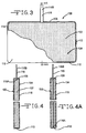
- Fig. 3 is perspective view, partly broken away, of an
anode 10 according to the present invention. - Fig. 4 is a cross-sectional view along line 4-4 of Fig. 3.
- Fig. 4A is an alternate embodiment of the
anode 10 shown in Fig. 4. - Figs. 5 and 6 are alternate embodiments of anodes according to the present invention.
- An electrochemical cell according to the present invention comprises an anode of lithium metal and its intermetallic compounds including, for example, Li-Si, Li-Al, Li-B, Li-Mg, and Li-Si-B alloys. The greater the amounts of the intermetallic compound such as aluminum present by weight in the alloy, however, the lower the energy density of the cell. The form of the anode may vary, but preferably the anode is a thin sheet or foil of the lithium metal.
- The electrochemical cell further comprises a cathode of electrically conductive material which serves as the other electrode. The cathode is preferably of solid materials and the electrochemical reaction at the cathode involves conversion of ions which migrate from the anode to the cathode into atomic or molecular forms. The solid cathode may comprise a first active material of a carbonaceous chemistry and a second active material of a metal element, a metal oxide, a mixed metal oxide and a metal sulfide, and combinations thereof. The metal oxide, the mixed metal oxide and the metal sulfide of the second active material have a relatively lower energy density but a relatively higher rate capability than the first carbonaceous active material.
- More particularly, the first active material is of a relatively high energy density and a relatively low rate capability in comparison to the second cathode active material. The first active material is preferably a carbonaceous compound prepared from carbon and fluorine, which includes graphitic and nongraphitic forms of carbon, such as coke, charcoal or activated carbon. Fluorinated carbon is represented by the formula (CFx)n wherein x varies between about 0.1 to 1.9 and preferably between about 0.5 and 1.2, and (C2F)n, wherein n refers to the number of monomer units which can vary widely.
- The cathode design further includes a second active material formed by the chemical addition, reaction, or otherwise intimate contact of various metal oxides, metal sulfides and/or metal elements, preferably during thermal treatment, sol-gel formation, chemical vapor deposition or hydrothermal synthesis in mixed states. The active materials thereby produced contain metals, oxides and sulfides of Groups IB, IIB, IIIB, IVB, VB, VIB, VIIB and VIII, which includes the noble metals and/or other oxide and sulfide compounds. A preferred second cathode active material is a reaction product of at least silver and vanadium.
- One preferred mixed metal oxide is a transition metal oxide having the general formula SMxV2Oy where SM is a metal selected from Groups IB to VIIB and VIII of the Periodic Table of Elements, and wherein x is about 0.30 to 2.0 and y is about 4.5 to 6.0 in the general formula. By way of illustration, and in no way intended to be limiting, one exemplary cathode active material comprises silver vanadium oxide having the general formula AgxV2Oy in any one of its many phases, i.e., β-phase silver vanadium oxide having in the general formula x = 0.35 and y = 5.8, γ-phase silver vanadium oxide having in the general formula x = 0.80 and y = 5.40, and ε-phase silver vanadium oxide having in the general formula x = 1.0 and y = 5.5, and combination and mixtures of phases thereof. For a more detailed description of such cathode active materials reference is made to
U.S. Pat. No. 4,310,609 to Liang et al. , which is assigned to the assignee of the present invention and incorporated herein by reference. - Another preferred composite transition metal oxide cathode material includes V2Oz wherein z ≤ 5 combined with Ag2O having silver in either the silver(II), silver(I) or silver(0) oxidation state and CuO with copper in either the copper(II), copper(I) or copper(0) oxidation state to provide the mixed metal oxide having the general formula CuxAgyV2Oz, (CSVO). Thus, the composite cathode active material may be described as a metal oxide-metal oxide-metal oxide, a metal-metal oxide-metal oxide, or a metal-metal-metal oxide and the range of material compositions found for CuxAgyV2Oz is preferably about 0.01 ≤ z ≤ 6.5. Typical forms of CSVO are Cu0.26Ag0.67V2Oz with z being about 5.5 and Cu0.5Ag0.5V2Oz with z being about 5.75. The oxygen content is designated by z since the exact stoichiometric proportion of oxygen in CSVO can vary depending on whether the cathode material is prepared in an oxidizing atmosphere such as air or oxygen, or in an inert atmosphere such as argon, nitrogen and helium. For a more detailed description of this cathode active material reference is made to
U.S. Patent Nos. 5,472,810 to Takeuchi et al. and5,516,340 to Takeuchi et al. , both of which are assigned to the assignee of the present invention and incorporated herein by reference. - In a broader sense, it is contemplated by the scope of the present invention that the first active material of the present cathode design is any material which has a relatively higher energy density but a relatively lower rate capability than the second active material. In addition to fluorinated carbon, Ag2O, Ag2O2, CuF2, Ag2CrO4, MnO2 and even SVO itself are useful as the first active material, and in addition to silver vanadium oxide and copper silver vanadium oxide, V2O5, MnO2, LiCoO2, LiNiO2, LiMn2O4, TiS2, Cu2S, FeS, FeS2, copper oxide, copper vanadium oxide, and mixtures thereof are useful as the second active material.
- Before fabrication into an electrode for incorporation into an electrochemical cell, the first and second cathode active materials prepared as described above are preferably mixed with a binder material such as a powdered fluoro-polymer, more preferably powdered polytetrafluoroethylene or powdered polyvinylidene flouride present at about 1 to about 5 weight percent of the cathode mixture. Further, up to about 10 weight percent of a conductive diluent is preferably added to the cathode mixture to improve conductivity. Suitable materials for this purpose include acetylene black, carbon black and/or graphite or a metallic powder such as powdered nickel, aluminum, titanium, and stainless steel. The preferred cathode active mixture thus includes a powdered fluoro-polymer binder present at about 3 weight percent, a conductive diluent present at about 3 weight percent and about 94 weight percent of either the first or the second cathode active materials.
- Cathode components are prepared by rolling, spreading or pressing the first and second cathode active materials onto opposite sides of a suitable current collector selected from the group consisting of stainless steel, titanium, tantalum, platinum, gold, aluminum, cobalt nickel alloys, highly alloyed ferritic stainless steel containing molybdenum and chromium, and nickel-, chromium-, and molybdenum-containing alloys. The preferred current collector material is titanium, and most preferably the titanium cathode current collector has a thin layer of graphite/carbon paint applied thereto. Cathodes prepared as described above may be in the form of one or more plates operatively associated with at least one or more plates of the lithium anode material, or in the form of a strip wound with a corresponding strip of lithium in a structure similar to a "jellyroll".
- In order to prevent internal short circuit conditions, the cathode is separated from the lithium anode by a suitable separator material. The separator is of electrically insulative material, and the separator material also is chemically unreactive with the anode and cathode active materials and both chemically unreactive with and insoluble in the electrolyte. In addition, the separator material has a degree of porosity sufficient to allow flow there through of the electrolyte during the electrochemical reaction of the cell. Illustrative separator materials include fabrics woven from fluoropolymeric fibers including polyvinylidine fluoride, polyethylenetetrafluoroethylene, and polyethylenechlorotrifluoroethylene used either alone or laminated with a fluoropolymeric microporous film, non-woven glass, polypropylene, polyethylene, glass fiber materials, ceramics, a polytetrafluoroethylene membrane commercially available under the designation ZITEX (Chemplast Inc.), a polypropylene membrane commercially available under the designation CELGARD (Celanese Plastic Company, Inc.) and a membrane commercially available under the designation DEXIGLAS (C.H. Dexter, Div., Dexter Corp.).
- The electrochemical cell further includes a nonaqueous, ionically conductive electrolyte which serves as a medium for migration of ions between the anode and the cathode during electrochemical reactions of the cell. The electrochemical reactions at the electrodes involve conversion of ions in atomic or molecular forms which migrate from the anode to the cathode. Thus, suitable nonaqueous electrolytes are substantially inert to the anode and cathode materials, and they exhibit those physical properties necessary for ionic transport, namely, low viscosity, low surface tension and wettability.
- A suitable electrolyte has an inorganic, ionically conductive salt dissolved in a nonaqueous solvent, and more preferably, the electrolyte includes an ionizable lithium salt dissolved in a mixture of aprotic organic solvents comprising a low viscosity solvent and a high permittivity solvent. Suitable lithium salts capable of serving as a vehicle for migration of lithium ions to intercalate or react with the cathode active materials include LiPF6, LiBF4, LiAsF6, LiSbF6, LiClO4, LiO2, LiAlCl4, LiGaCl4, LiC(SC)2CF3)3, LiN(SO2CF3)2, LiSCN, LiO3SCF3, LiC6F5SO3, LiO2CCF3, LiSO6F, LiB(C6H5)4, LiCF3SO3, and mixtures thereof.
- Low viscosity solvents useful with the present invention include esters, linear and cyclic ethers and dialkyl carbonates such as tetrahydrofuran (THF), methyl acetate (MA), diglyme, trigylme, tetragylme, dimethyl carbonate (DMC), 1,2-dimethoxyethane (DME), 1,2-diethoxyethane (DEE), 1-ethoxy,2-methoxyethane (EME), ethyl methyl carbonate, methyl propyl carbonate, ethyl propyl carbonate, diethyl carbonate, dipropyl carbonate, and mixtures thereof, and high permittivity solvents include cyclic carbonates, cyclic esters and cyclic amides such as propylene carbonate (PC), ethylene carbonate (EC), butylene carbonate, acetonitrile, dimethyl sulfoxide, dimethyl formamide, dimethyl acetamide, γ-valerolactone, γ-butyrolactone (GBL), N-methyl-pyrrolidinone (NMP), and mixtures thereof. The preferred electrolyte is 0.8M to 1.5M LiAsF6 or LiPF6 dissolved in a 50:50 mixture, by volume, of propylene carbonate as the preferred high permittivity solvent and 1,2-dimethoxyethane as the preferred low viscosity solvent.
- According to the present invention, CFx cathode material, which provides a relatively low power or rate capability but a relatively high energy density or volumetric capability, and SVO cathode material, which has a relatively low energy density but a relatively high rate capability, are individually pressed on opposite sides of a current collector screen. This results in so both materials being in direct contact with the current collector. Therefore, one exemplary cathode design has the following configuration:
Design 1: SVO/current collector/CFx - One important aspect of the present invention is that the high rate cathode material (SVO) maintains direct contact with the current collector with the relatively low rate/high capacity material (CFx) being in direct contact with the high rate material. Thus, another cathode design has the following configuration:
Design 2: SVO/current collector/SVO/CFx - Another alternative cathode design has the following configuration:
Design 3: CFx/SVO/current collector/SVO/CFx - Still another cathode design has the following configuration:
Design 4: SVO/CFx/current collector/CFx/SVO - In the above cathode designs, the common structure is that they all utilize a single cathode current collector, which results in a significantly lower material cost in comparison to the sandwich cathode design of: SVO/current collector/CFx/current collector/SVO previously discussed with respect to
U.S. Patent No. 6,551,747 to Gan . Among the above cathode configurations, designs 1 and 2 are preferred over designs 3 and 4 for maintaining high power capability in a lithium electrochemical cell. - Additionally, the present invention provides the following cell design:
anode/[separator(s)/cathode/separator(s)/anode]n
wherein n ≥ 1 and the cathode has one of three structures shown above. This is different than the sandwich cell design ofU.S. Patent No. 6,551,747 to Gan in which only the SVO active material faces the anode. In the present design, both the SVO and CFx materials face a portion of the lithium anode. - CFx has significantly higher volumetric capacity than that of SVO. For example, the preferred ε-phase silver vanadium oxide (AgV2O5.5) has a theoretical volumetric capacity of 1.37 Ah/ml. By comparison, the theoretical volumetric capacity of CFx (x = 1.1) is 2.42 Ah/ml, which is 1.77 times that of ε-phase silver vanadium oxide. In order to optimize the final cell capacity, the amount of CFx material should be maximized and the amount of SVO material minimized to the extent where it is still practical in engineering and acceptable in electrochemical performance. Beneficially, the use of two disparate cathode materials means that the cell's discharge voltage can be altered or profiled to the requirements of a particular application by adjusting the gram amount of SVO to that of CFx.
- Further, end of service life indication is the same as that of a standard Li/SVO cell and of a sandwich cathode cell. And, it has been determined that the SVO and CFx active materials reach end of life at the same time. This is the case regardless of the use of the cell. Since both electrode materials reach end of service life at the same time, no energy capacity is wasted.
- To further lower the cost of cell manufacturing, a screen-less anode design is used. For a typical lithium cell design, in order to utilize the cell volume efficiently, the relative capacity ratio of the anode vs. the cathode is designed around 1 ± 0.3. Since lithium is consumed during cell discharge, the lithium foil shrinks and part of the lithium can loss contact with the remaining lithium contacted to the anode current collector.
- As shown in Figs. 1 and 2, a typical
prior art anode 10 comprises an anodecurrent collector 12 in the form of a screen-type structure. Thecurrent collector 12 has a frontmajor side 14 and an opposed backmajor side 16, both extending to and meeting with an upper edge 18, alower edge 20, aright edge 22 and aleft edge 24. The current collector is in the form of a screen with theedges perforations 26 extending to the opposed major sides. Theperforations 26 are shown having a diamond shape, but they can have virtually any shape and be of a density ranging from about 20% to as much as 90% of the current collector area. Anintegral tab 28 having a width significantly less than the distance between the right and leftedges upper edge 16. - The anode is built by press contacting two
pieces major sides lithium sheets perforations 26. The lithium sheets are somewhat larger than thecurrent collector 12 so that theperipheral border separator 34 envelopes the lithium supported on the current collector except for the extendingtab 28. The anodecurrent collector 12 then serves as a path of electrical continuity between the lithium metal and the external circuit. Understandably, the cost of an anode having a current collector is higher than one devoid of an anode current collector. - Since lithium metal is a very good electrical conductor, the need for an anode current collector can be avoided if at the end of cell discharge life, isolation of the lithium can be prevented. In that respect, another embodiment having n = 1 or n > 1 in the previously described cell configuration of: anode/[separator(s)/cathode/separator(s)/anode]n uses a metal lead in place of an anode current collector screen. Figs. 3 and 4 illustrate this embodiment directed to a
screen-less anode 100. Theanode 100 compriseslithium metal 102, or alloy thereof, in the form of a foil having a frontmajor side 104 and an opposed backmajor side 106, both extending to and meeting with anupper edge 108, alower edge 110, aright edge 112 and aleft edge 114. The lithium edges 108, 110, 112 and 114 form a peripheral border. Atab 116 in the form of a metal strip having a relatively narrow, but substantially constant width significantly less than the distance between the right and leftedges upper edge 108 of thelithium foil 102. Thetab 116 has aproximal end 116A embedded a relatively short distance into the lithium and adistal end 116B. Thetab 116 is preferably centered between the front andback sides lithium 102 and an external circuit when thedistal end 116B is connected to a casing (not shown) serving as the negative cell terminal. Thetab 116 could also be contacted to one or theother sides separator 118 envelopes thelithium foil 102 except for the extending portion of thetab 116. Suitable materials for thetab 116 include nickel and stainless steel, as well as titanium, copper, tungsten, tantalum, and alloys thereof. - Preferably, the
tab 116 is of a width that is from about 1% to 20% the width of theanode foil 102 measured from theright edge 112 to theleft edge 114 thereof. Also, theproximal tab end 116A extends into thelithium foil 102 from about 2% (Fig. 4) to about 100% (Fig. 4A) of the distance measured from theupper edge 108 to thelower edge 110 thereof. - Fig. 5 illustrates an alternate embodiment of an
anode 200 according to the invention. The anode comprises atab 216 having a strip-shapedproximal end 216A and adistal end 216B. As before, thetab 216 is preferably centered between the front and back sides of the anode and serves as a path of electrical continuity between thelithium 102 and an external circuit when thedistal end 216B is connected to a casing (not shown) serving as the negative cell terminal. In this embodiment, theproximal end 216A has a triangular shape while thedistal end 216B is of a strip having a substantially constant width. Fig. 6 illustrates ananode 300 comprising atab 316 having a circular-shapedproximal end 316A and adistal end 316B of a substantially constant width. Understandably, the triangular-shaped and circular-shaped proximal ends 216A, 316A for therespective tabs tabs - A relatively high anode to cathode capacity ratio (A/C ratio) makes the
screen-less anode 100 possible. Preferably, the anode active material to the cathode active material based on a gram amount of the active materials has an A/C ratio greater than about 1.2 to up to about 5. Due to the use of extra lithium, i.e., a relatively thicker foil, thelithium foil 102 is not totally consumed within the useful cell discharge life. The excess lithium serves as an anode current collector throughout cell discharge life. In addition, due to the presence of the excess lithium, the cell performance variation at the end of discharge, caused by a lithium "Swiss cheese" effect is eliminated. Several examples of electrode assemblies incorporating a screen-less anode are shown below: - For a single cathode design (n = 1), the lithium anode can be directly contacted to the inner surface of the cell casing. In this design, the cell case wall serves as the anode current collector and the electrode assembly has the following configuration:
case wall/lithium metal/separator/cathode/lithium metal/case wall - Similar to a lithium cell incorporating a sandwich cathode design, the energy of high volumetric capacity CFx material is converted into or used as high power energy of the SVO material. During high energy pulsing, both the SVO and CFx materials contribute to the delivered energy. The relative contribution depends on the pulse current density, as well as on the pulse length or the level of energy delivered. For short pulses, SVO provides more than 50% of the required energy. The background voltage profile is controlled by the SVO to CFx capacity ratio.
- Compared with a sandwich SVO/CFx/SVO cathode design, the cell designs of the present invention have higher energy density due to the use of only one layer of cathode current collector. The comparative rate capability is slightly lower under the same cathode/anode interface area design. However, designing the cells with larger interface cathode to anode surface area compensates for this. Accordingly, the use of only one layer of cathode current collector and a screen-less anode or an anode with metal strip type current collector significantly lowers the manufacturing cost of high to medium rate lithium cells for implantable medical device applications. The concept can be used in various cell designs, including those having a prismatic or cylindrical shape incorporating an electrode assembly of a multiplate cathode with a serpentine anode, a multiplate cathode/multiplate anode, or a jellyroll electrode assembly, among others.
- Cells of the present invention are particularly well suited for powering implantable medical devices requiring a relatively low to medium discharge rate. An exemplary device is a cardiac pacemaker. In such devices, it is important to have a reliable and predictable end-of-life (EOL) or end-of-replacement indicator (ERI) for the device. While Li/CFx cells are generally acceptable as a power source for these types of applications, this chemistry has a relatively flat or constant discharge curve until just before end of life, when it becomes somewhat steep. This makes it difficult for a medical professional to time and plan replacement surgery. In that light, in addition to augmenting the discharge performance of a CFx cell, the SVO component of the cathode electrode provides a predictable and familiar EOL discharge curve.
- In the discharge of a cathode according to the present invention, the SVO component is the power source from about 3.6 volts through the first voltage plateau at about 3.2 volts to about 2.8 volts. At about 2.8 volts, the CFx component is discharged until about 2.6 volts, at which time the CFx material is essentially depleted. Then, the SVO material is discharged again to EOL at 2.0 volts. The discharge of a Li/SVO cell at about 2.6 volts is referred to as the second voltage plateau. In this manner, the present cathode configuration provides a cell with increased safety characteristics under short circuit conditions along with a very reliable and predictable EOL indication for replacement surgery.
- The assembly of the cells described herein is preferably in the form of a wound element configuration. That is, the fabricated anode, cathode and separator are wound together in a "jellyroll" type configuration or "wound element cell stack" such that the anode is on the outside of the roll to make electrical contact with the cell case in a case-negative configuration. Using suitable top and bottom insulators, the wound cell stack is inserted into a metallic case of a suitable size dimension. The metallic case may comprise materials such as stainless steel, mild steel, nickel-plated mild steel, titanium, tantalum or aluminum, but not limited thereto, so long as the metallic material is compatible for use with components of the cell.
- The cell header comprises a metallic disc-shaped body with a first hole to accommodate a glass-to-metal seal/terminal pin feedthrough and a second hole for electrolyte filling. The glass used is of a corrosion resistant type having up to about 50% by weight silicon such as
CABAL 12, TA 23, FUSITE 425 or FUSITE 435. The positive terminal pin feedthrough preferably comprises titanium although molybdenum, aluminum, nickel alloy, or stainless steel can also be used. The cell header is typically of a material similar to that of the case. The positive terminal pin supported in the glass-to-metal seal is, in turn, supported by the header, which is welded to the case containing the electrode stack. The cell is thereafter filled with the electrolyte solution described hereinabove and hermetically sealed such as by close-welding a stainless steel ball over the fill hole, but not limited thereto. - The above assembly describes a case-negative cell, which is the preferred construction of present invention cells. As is well known to those skilled in the art, however, the exemplary cells can also be constructed in case-positive configurations.
- It is appreciated that various modifications to the inventive concepts described herein may be apparent to those of ordinary skill in the art without departing from the spirit and scope of the present invention as defined by the appended claims.
Claims (39)
- An electrochemical cell, which comprises:a) a casing;b) an anode comprising a body of lithium as an anode active material contacted to an anode current collector devoid of a screen-type structure;c) a cathode of a cathode active material;d) a separator disposed between the anode and the cathode to prevent direct physical contact between them; ande) a nonaqueous electrolyte activating the anode and the cathode housed inside the casing.
- The electrochemical cell of claim 1 wherein the lithium body is not in contact with a casing sidewall.
- The electrochemical cell of claim 1 or 2 wherein the anode current collector is a strip of metal having a length extending to a proximal end and a distal end with its proximal end contacted by the lithium body and its distal end electrically connected to an anode terminal.
- The electrochemical cell of claim 3 wherein the lithium body has an upper edge and a spaced apart lower edge, both extending to and meeting with right and left edges defining an anode width and wherein a width of the metal strip is from about 1% to 20% the anode width measured from the right edge to the left edge thereof.
- The electrochemical cell of claim 3 or 4 wherein the metal strip extends into the lithium body from about 2% to about 100% of its height measured from the upper edge to the lower edge thereof.
- The electrochemical cell of any of claims 3 to 5 wherein the metal strip has a generally uniform width along its length from the proximal end to the distal end thereof.
- The electrochemical cell of any of claims 3 to 6 wherein the metal strip has either a triangular- or a circular-shaped proximal end.
- The electrochemical cell of any of claims 3 to 7 wherein the casing is the anode terminal.
- The electrochemical cell of any of claims 1 to 8 wherein the lithium is provided in an anode to cathode capacity ratio (A/C ratio) greater than about 1.2 based on a gram amount of the anode active material to the cathode active material.
- The electrochemical cell of claim 9 wherein A/C ratio is up to about 5.
- The electrochemical cell of any of claims 1 to 10 wherein the cathode active material is selected from the group consisting of silver vanadium oxide (SVO), copper silver vanadium oxide (CSVO), V2O5, MnO2, CuO2, TiS2, Cu2S, FeS, FeS2, copper vanadium oxide, CFx, Ag2O, Ag2O2, CuF, LiCoO2, LiNiO2, LiMnO2, Ag2CrO4, and mixtures thereof.
- An electrochemical cell, which comprises:a) a casing;b) an anode comprising lithium as an anode active material contacted to an anode current collector;c) a cathode of a first cathode active material having a relatively low energy density but a relatively high rate capability contacted to one side of a cathode current collector and with a second cathode active material having a relatively high energy density but a relatively low rate capability contacted to the other side of the cathode current collector, wherein the lithium is provided in an anode to cathode capacity ratio (A/C ratio) greater than about 1.2 based on a gram amount of the anode active material to the total gram amounts of the first and second cathode active materials;d) a separator disposed between the anode and the cathode to prevent direct physical contact between them; ande) a nonaqueous electrolyte activating the anode and the cathode housed inside the casing.
- The electrochemical cell of claim 12 wherein the second cathode active material faces the anode.
- The electrochemical cell of claim 12 or 13 wherein the anode current collector is devoid of a screen-type structure.
- The electrochemical cell of any of claims 12 to 14 wherein the lithium body is not in contact with a casing sidewall.
- The electrochemical cell of any of claims 12 to 15 wherein A/C ratio is up to about 5.
- The electrochemical cell of any of claims 12 to 16 wherein the anode and cathode are electrochemically associated with each other in a configuration of: anode/[separator/cathode/separator/anode]n, wherein n ≥ 1.
- The electrochemical cell of any of claims 12 to 17 wherein a casing sidewall serves as the anode current collector for an electrode assembly having a configuration of: casing sidewall/lithium/separator/cathode/lithium/casing sidewall.
- The electrochemical cell of any of claims 12 to 18 wherein the first cathode active material is selected from the group consisting of silver vanadium oxide (SVO), copper silver vanadium oxide (CSVO), V2O5, MnO2, LiCoO2, LiNiO2, LiMnO2, CuO2, TiS2, Cu2S, FeS, FeS2, copper oxide, copper vanadium oxide, and mixtures thereof, and the second cathode active material is selected from the group consisting of CFx. Ag2O, Ag2O2, CuF, Ag2CrO4, MnO2, SVO, and mixtures thereof.
- The electrochemical cell of any of claims 12 to 19 wherein the cathode has the configuration: SVO/current collector/CFx, with the CFx facing the anode.
- The electrochemical cell of any of claims 12 to 19 wherein the cathode has the configuration: SVO/current collector/SVO/CFx, with the CFx facing the anode.
- The electrochemical cell of any of claims 12 to 19 wherein the cathode has the configuration: CFx/SVO/current collector/SVO/CFx.
- An electrochemical cell, which comprises:a) a casing;b) an anode comprising a body of lithium as an anode active material contacted to an anode current collector devoid of a screen-type structure and wherein the lithium body is not in contact with a casing sidewall;c) a cathode of SVO as a first cathode active material contacting one side of a cathode current collector and CFx as a second cathode active material contacting the opposite side of the cathode current collector and facing the anode, wherein the cathode is provided in a configuration selected from the group consisting of:i) SVO/current collector/CFx;ii) SVO/current collector/SVO/CFx;iii) CFx/SVO/current collector/SVO/CFx; andiv) SVO/CFx/current collector/CFx/SVO;d) a separator disposed between the anode and the cathode to prevent direct physical contact between them; ande) a nonaqueous electrolyte activating the anode and the cathode housed inside the casing.
- The electrochemical cell of claim 23 wherein the cathode current collector is selected from the group consisting of stainless steel, titanium, tantalum, platinum, gold, aluminum, cobalt nickel alloys, highly alloyed ferritic stainless steel containing molybdenum and chromium, and nickel-, chromium-, and molybdenum-containing alloys.
- The electrochemical cell of claim 23 or 24 wherein the cathode current collector is titanium having a coating selected from the group consisting of graphite/carbon material, iridium, iridium oxide and platinum provided thereon.
- The electrochemical cell of any of claims 23 to 25 wherein the electrolyte has a first solvent selected from the group consisting of tetrahydrofuran, methyl acetate, diglyme, triglyme, tetraglyme, dimethyl carbonate, 1,2-dimethoxyethane, 1,2-diethoxyethane, 1-ethoxy-2-methoxyethane, ethyl methyl carbonate, methyl propyl carbonate, ethyl propyl carbonate, diethyl carbonate, dipropyl carbonate, and mixtures thereof, and a second solvent selected from the group consisting of propylene carbonate, ethylene carbonate, butylene carbonate, acetonitrile, dimethyl sulfoxide, dimethyl formamide, dimethyl acetamide, γ-valerolactone, γ-butyrolactone, N-methylpyrrolidinone, and mixtures thereof.
- The electrochemical cell of any of claims 23 to 26 wherein the electrolyte includes a lithium salt selected from the group consisting of LiPF6, LiBF4, LiAsF6, LiSbF6, LiClO4, LiO2, LiAlCl4, LiGaCl4, LiC(SO2CF3)3, LiN(SO2CF3)2, LiSCN, LiO3SCF3, LiC6F5SO3, LiO2CCF3, LiSO6F, LiB(C6H5)4, LiCF3SO3, and mixtures thereof.
- An implantable medical device, which comprises:a) a housing;b) a control circuitry contained inside the housing to control functioning of the medical device; andc) an electrochemical cell contained inside the housing for powering the control circuitry, the cell comprising:i) a casing;ii) an anode comprising a body of lithium as an anode active material contacted to an anode current collector devoid of a screen-type structure and wherein the lithium body is not in contact with a casing sidewall;iii) a cathode of a first cathode active material having a relatively low energy density but a relatively high rate capability contacted to one side of a cathode current collector with a second cathode active material having a relatively high energy density but a relatively low rate capability contacting the opposite side of the cathode current collector, and wherein the second cathode active material faces the anode; andiv) a nonaqueous electrolyte activating the anode and the cathode housed inside the casing.
- The medical device of claim 28 wherein the first cathode active material is selected from the group consisting of SVO, CSVO, V2O5, MnO2, LiCoO2, LiNiO2, LiMnO2, CuO2, TiS2, Cu2S, FeS, FeS2, copper oxide, copper vanadium oxide, and mixtures thereof.
- The medical device of claim 28 or 29 wherein the second cathode active material is selected from the group consisting of CFx. Ag2O, Ag2O2, CuF, Ag2CrO4, MnO2, and mixtures thereof.
- The medical device of any of claims 28 to 30 wherein the cathode has a configuration selected from the group consisting of: SVO/current collector/CFx, SVO/current collector/SVO/CFx, and CFx/SVO/current collector/SVO/CFx, with the CFx, facing the lithium anode.
- The medical device of any of claims 28 to 31 selected from the group consisting of a cardiac pacemaker, a defibrillator, a neurostimulator, a drug pump, a hearing assist device, and a bone growth device.
- A method for providing an electrochemical cell, comprising the steps of:a) providing a casing;b) providing an anode comprising a body of lithium as an anode active material contacted to an anode current collector devoid of a screen-type structure;c) providing a cathode of a cathode active material;d) disposing a separator between the anode and the cathode to prevent direct physical contact between them; ande) activating the anode and the cathode housed inside the casing with a nonaqueous electrolyte and with the lithium body not contacting a casing sidewall.
- The method of claim 33 including providing the anode current collector as a strip of metal having a length extending to a proximal and a distal end and contacting the proximal strip end to the lithium body and electrically connecting the distal strip end to the casing serving as an anode terminal.
- The method of claim 33 or 34 including providing the lithium in an anode to cathode capacity ratio (A/C ratio) greater than about 1.2 based on a gram amount of the anode active material to the cathode active material.
- The method of any of claims 33 to 35 including selecting the cathode active material from the group consisting of silver vanadium oxide (SVO), copper silver vanadium oxide (CSVO), V2O5, MnO2, CuO2, TiS2, Cu2S, FeS, FeS2, copper vanadium oxide, CFx, Ag2O, Ag2O2, CuF, LiCoO2, LiNiO2, LiMnO2, Ag2CrO4, and mixtures thereof.
- A method for providing an electrochemical cell, comprising the steps of:a) providing a casing;b) providing an anode comprising lithium as an anode active material contacted to an anode current collector;c) providing a cathode by contacting a first cathode active material having a relatively low energy density but a relatively high rate capability to one side of a cathode current collector and a second cathode active material having a relatively high energy density but a relatively low rate capability to the other side of the cathode current collector, and further providing the lithium in an anode to cathode capacity ratio (A/C ratio) greater than about 1.2 up to about 5 based on a gram amount of the anode active material to the total gram amounts of the first and second cathode active materials;d) disposing a separator between the anode and the cathode to prevent direct physical contact between them; ande) activating the anode and the cathode housed inside the casing with a nonaqueous electrolyte.
- The method of claim 37 including electrically associating the anode and cathode with each other in a configuration of: anode/[separator/cathode/separator/anode]n, wherein n ≥ 1.
- A method for providing an electrochemical cell, comprising the steps of:a) providing a casing;b) providing an anode comprising a body of lithium as an anode active material contacted to an anode current collector devoid of a screen-type structure;c) providing a cathode by contacting SVO as a first cathode active material to one side of a cathode current collector and CFx as a second cathode active material to the opposite side of the cathode current collector and facing the anode, wherein the cathode is provided in a configuration selected from the group consisting of:i) SVO/current collector/CFx;ii) SVO/current collector/SVO/CFx;iii) CFx/SVO/current collector/SVO/CFx; andiv) SVO/CFx/current collector/CFx/SVO;d) disposing a separator between the anode and the cathode to prevent direct physical contact between them; ande) activating the anode and the cathode housed inside the casing with a nonaqueous electrolyte and with the lithium body not contacting a casing sidewall.
Applications Claiming Priority (1)
| Application Number | Priority Date | Filing Date | Title |
|---|---|---|---|
| US70479605P | 2005-08-02 | 2005-08-02 |
Publications (3)
| Publication Number | Publication Date |
|---|---|
| EP1768203A2 true EP1768203A2 (en) | 2007-03-28 |
| EP1768203A3 EP1768203A3 (en) | 2007-06-13 |
| EP1768203B1 EP1768203B1 (en) | 2011-10-05 |
Family
ID=37708456
Family Applications (1)
| Application Number | Title | Priority Date | Filing Date |
|---|---|---|---|
| EP06254056A Expired - Fee Related EP1768203B1 (en) | 2005-08-02 | 2006-08-02 | Battery electrodes |
Country Status (1)
| Country | Link |
|---|---|
| EP (1) | EP1768203B1 (en) |
Cited By (4)
| Publication number | Priority date | Publication date | Assignee | Title |
|---|---|---|---|---|
| EP2504876A1 (en) * | 2009-11-24 | 2012-10-03 | The Gillette Company | Electrochemical cells with improved separator and electrolyte combination |
| DE102011084009A1 (en) * | 2011-10-05 | 2013-04-11 | Varta Microbattery Gmbh | Lithium-ion cells with improved properties |
| CN108295868A (en) * | 2018-03-06 | 2018-07-20 | 湖北文理学院 | AgCrO2-CuCr2O4Composite material, preparation method and application |
| CN111081974A (en) * | 2019-12-14 | 2020-04-28 | 陕西煤业化工技术研究院有限责任公司 | Lithium thionyl chloride battery cathode piece containing asphalt coke activated carbon catalytic material and preparation method thereof |
Citations (5)
| Publication number | Priority date | Publication date | Assignee | Title |
|---|---|---|---|---|
| US4310609A (en) | 1979-12-17 | 1982-01-12 | Wilson Greatbatch Ltd. | Metal oxide composite cathode material for high energy density batteries |
| US5180642A (en) | 1992-02-24 | 1993-01-19 | Medtronic, Inc. | Electrochemical cells with end-of-service indicator |
| US5472810A (en) | 1993-03-17 | 1995-12-05 | W. Greatbatch Ltd. | Copper, silver, vanadium oxide composite cathode material for high energy density batteries |
| US5516340A (en) | 1993-03-17 | 1996-05-14 | Wilson Greatbatch Ltd. | Process for making a metal oxide composite cathode material for high energy density batteries |
| US6551747B1 (en) | 2000-04-27 | 2003-04-22 | Wilson Greatbatch Ltd. | Sandwich cathode design for alkali metal electrochemical cell with high discharge rate capability |
Family Cites Families (2)
| Publication number | Priority date | Publication date | Assignee | Title |
|---|---|---|---|---|
| DE19633463A1 (en) * | 1995-09-02 | 1997-03-06 | Basf Magnetics Gmbh | Simple reliable prodn. of reversible lithium electrodes for electrochemical cell, esp. lithium battery |
| NO20004855L (en) * | 1999-09-30 | 2001-04-02 | Sony Corp | Solid electrolyte cell |
-
2006
- 2006-08-02 EP EP06254056A patent/EP1768203B1/en not_active Expired - Fee Related
Patent Citations (5)
| Publication number | Priority date | Publication date | Assignee | Title |
|---|---|---|---|---|
| US4310609A (en) | 1979-12-17 | 1982-01-12 | Wilson Greatbatch Ltd. | Metal oxide composite cathode material for high energy density batteries |
| US5180642A (en) | 1992-02-24 | 1993-01-19 | Medtronic, Inc. | Electrochemical cells with end-of-service indicator |
| US5472810A (en) | 1993-03-17 | 1995-12-05 | W. Greatbatch Ltd. | Copper, silver, vanadium oxide composite cathode material for high energy density batteries |
| US5516340A (en) | 1993-03-17 | 1996-05-14 | Wilson Greatbatch Ltd. | Process for making a metal oxide composite cathode material for high energy density batteries |
| US6551747B1 (en) | 2000-04-27 | 2003-04-22 | Wilson Greatbatch Ltd. | Sandwich cathode design for alkali metal electrochemical cell with high discharge rate capability |
Cited By (5)
| Publication number | Priority date | Publication date | Assignee | Title |
|---|---|---|---|---|
| EP2504876A1 (en) * | 2009-11-24 | 2012-10-03 | The Gillette Company | Electrochemical cells with improved separator and electrolyte combination |
| DE102011084009A1 (en) * | 2011-10-05 | 2013-04-11 | Varta Microbattery Gmbh | Lithium-ion cells with improved properties |
| CN108295868A (en) * | 2018-03-06 | 2018-07-20 | 湖北文理学院 | AgCrO2-CuCr2O4Composite material, preparation method and application |
| CN108295868B (en) * | 2018-03-06 | 2020-11-06 | 湖北文理学院 | AgCrO2-CuCr2O4Composite material, preparation method and application thereof |
| CN111081974A (en) * | 2019-12-14 | 2020-04-28 | 陕西煤业化工技术研究院有限责任公司 | Lithium thionyl chloride battery cathode piece containing asphalt coke activated carbon catalytic material and preparation method thereof |
Also Published As
| Publication number | Publication date |
|---|---|
| EP1768203B1 (en) | 2011-10-05 |
| EP1768203A3 (en) | 2007-06-13 |
Similar Documents
| Publication | Publication Date | Title |
|---|---|---|
| EP1150366B1 (en) | Sandwich cathode design for alkali metal electrochemical cell with high discharge rate capability | |
| US6171729B1 (en) | Control of swelling in alkali metal electrochemical cells | |
| US7018743B2 (en) | Dual chemistry electrode design | |
| EP1796190B1 (en) | Sandwich cathode electrochemical cell with wound electrode assembly | |
| US6692865B2 (en) | Double current collector cathode design using mixtures of two active materials for alkali metal or ion electrochemical cells | |
| US6692871B2 (en) | Double current collector cathode design for alkali metal electrochemical cells having short circuit safety characteristics | |
| EP1156544A2 (en) | Efficient cell stack for cells with double screen sandwich cathodes | |
| US7776470B2 (en) | Anode-to-cathode capacity ratios for SVO/CF x hybrid cathode electrochemical cells | |
| EP1331683A2 (en) | Cathode active material coated with a metal oxide for incorporation into a lithium electrochemical cell | |
| US6926991B2 (en) | SVO/CFx parallel cell design within the same casing | |
| EP1310271B1 (en) | Electrode design for implantable device applications that require the elective replacement indicator (ERI) | |
| US8871379B2 (en) | Screen-less anode design concepts for low cost lithium electrochemical cells for use in implantable medical device applications | |
| EP1143544A2 (en) | Application of Gamma-SVO and mixture of Gamma-SVO/ Epsilon-SVO in high rate electrochemical lithium cells containing SVO/CFx/SVO sandwich cathodes | |
| US20030134188A1 (en) | Sandwich electrode design having relatively thin current collectors | |
| US7108942B1 (en) | Efficient electrode assembly design for cells with alkali metal anodes | |
| US8192867B2 (en) | Hybrid cathode design for an electrochemical cell | |
| US7033707B2 (en) | Organic cyclic carbonate additives for nonaqueous electrolyte in alkali metal electrochemical cells | |
| EP1768203B1 (en) | Battery electrodes | |
| US7273674B1 (en) | Primary electrochemical cell having scalloped electrodes | |
| EP1914823B1 (en) | Hybrid cathode design for an electrochemical cell |
Legal Events
| Date | Code | Title | Description |
|---|---|---|---|
| PUAI | Public reference made under article 153(3) epc to a published international application that has entered the european phase |
Free format text: ORIGINAL CODE: 0009012 |
|
| AK | Designated contracting states |
Kind code of ref document: A2 Designated state(s): AT BE BG CH CY CZ DE DK EE ES FI FR GB GR HU IE IS IT LI LT LU LV MC NL PL PT RO SE SI SK TR |
|
| AX | Request for extension of the european patent |
Extension state: AL BA HR MK YU |
|
| PUAL | Search report despatched |
Free format text: ORIGINAL CODE: 0009013 |
|
| AK | Designated contracting states |
Kind code of ref document: A3 Designated state(s): AT BE BG CH CY CZ DE DK EE ES FI FR GB GR HU IE IS IT LI LT LU LV MC NL PL PT RO SE SI SK TR |
|
| AX | Request for extension of the european patent |
Extension state: AL BA HR MK YU |
|
| 17P | Request for examination filed |
Effective date: 20071210 |
|
| AKX | Designation fees paid |
Designated state(s): DE FR IT SE |
|
| 17Q | First examination report despatched |
Effective date: 20080317 |
|
| RAP1 | Party data changed (applicant data changed or rights of an application transferred) |
Owner name: GREATBATCH LTD. |
|
| RIC1 | Information provided on ipc code assigned before grant |
Ipc: H01M 10/052 20100101AFI20101222BHEP |
|
| GRAP | Despatch of communication of intention to grant a patent |
Free format text: ORIGINAL CODE: EPIDOSNIGR1 |
|
| GRAS | Grant fee paid |
Free format text: ORIGINAL CODE: EPIDOSNIGR3 |
|
| GRAA | (expected) grant |
Free format text: ORIGINAL CODE: 0009210 |
|
| AK | Designated contracting states |
Kind code of ref document: B1 Designated state(s): DE FR IT SE |
|
| REG | Reference to a national code |
Ref country code: DE Ref legal event code: R096 Ref document number: 602006024846 Country of ref document: DE Effective date: 20111215 |
|
| PG25 | Lapsed in a contracting state [announced via postgrant information from national office to epo] |
Ref country code: SE Free format text: LAPSE BECAUSE OF FAILURE TO SUBMIT A TRANSLATION OF THE DESCRIPTION OR TO PAY THE FEE WITHIN THE PRESCRIBED TIME-LIMIT Effective date: 20111005 |
|
| PLBE | No opposition filed within time limit |
Free format text: ORIGINAL CODE: 0009261 |
|
| STAA | Information on the status of an ep patent application or granted ep patent |
Free format text: STATUS: NO OPPOSITION FILED WITHIN TIME LIMIT |
|
| PG25 | Lapsed in a contracting state [announced via postgrant information from national office to epo] |
Ref country code: IT Free format text: LAPSE BECAUSE OF FAILURE TO SUBMIT A TRANSLATION OF THE DESCRIPTION OR TO PAY THE FEE WITHIN THE PRESCRIBED TIME-LIMIT Effective date: 20111005 |
|
| 26N | No opposition filed |
Effective date: 20120706 |
|
| REG | Reference to a national code |
Ref country code: DE Ref legal event code: R097 Ref document number: 602006024846 Country of ref document: DE Effective date: 20120706 |
|
| REG | Reference to a national code |
Ref country code: FR Ref legal event code: PLFP Year of fee payment: 10 |
|
| REG | Reference to a national code |
Ref country code: FR Ref legal event code: PLFP Year of fee payment: 11 |
|
| REG | Reference to a national code |
Ref country code: FR Ref legal event code: PLFP Year of fee payment: 12 |
|
| REG | Reference to a national code |
Ref country code: FR Ref legal event code: PLFP Year of fee payment: 13 |
|
| PGFP | Annual fee paid to national office [announced via postgrant information from national office to epo] |
Ref country code: DE Payment date: 20180717 Year of fee payment: 13 Ref country code: FR Payment date: 20180712 Year of fee payment: 13 |
|
| REG | Reference to a national code |
Ref country code: DE Ref legal event code: R119 Ref document number: 602006024846 Country of ref document: DE |
|
| PG25 | Lapsed in a contracting state [announced via postgrant information from national office to epo] |
Ref country code: FR Free format text: LAPSE BECAUSE OF NON-PAYMENT OF DUE FEES Effective date: 20190831 Ref country code: DE Free format text: LAPSE BECAUSE OF NON-PAYMENT OF DUE FEES Effective date: 20200303 |