EP1767827B1 - Automatic transmission control device - Google Patents
Automatic transmission control device Download PDFInfo
- Publication number
- EP1767827B1 EP1767827B1 EP06016111A EP06016111A EP1767827B1 EP 1767827 B1 EP1767827 B1 EP 1767827B1 EP 06016111 A EP06016111 A EP 06016111A EP 06016111 A EP06016111 A EP 06016111A EP 1767827 B1 EP1767827 B1 EP 1767827B1
- Authority
- EP
- European Patent Office
- Prior art keywords
- shift
- rotational speed
- deceleration
- control device
- automatic transmission
- Prior art date
- Legal status (The legal status is an assumption and is not a legal conclusion. Google has not performed a legal analysis and makes no representation as to the accuracy of the status listed.)
- Expired - Fee Related
Links
Images


Classifications
-
- F—MECHANICAL ENGINEERING; LIGHTING; HEATING; WEAPONS; BLASTING
- F16—ENGINEERING ELEMENTS AND UNITS; GENERAL MEASURES FOR PRODUCING AND MAINTAINING EFFECTIVE FUNCTIONING OF MACHINES OR INSTALLATIONS; THERMAL INSULATION IN GENERAL
- F16H—GEARING
- F16H61/00—Control functions within control units of change-speed- or reversing-gearings for conveying rotary motion ; Control of exclusively fluid gearing, friction gearing, gearings with endless flexible members or other particular types of gearing
- F16H61/66—Control functions within control units of change-speed- or reversing-gearings for conveying rotary motion ; Control of exclusively fluid gearing, friction gearing, gearings with endless flexible members or other particular types of gearing specially adapted for continuously variable gearings
- F16H61/662—Control functions within control units of change-speed- or reversing-gearings for conveying rotary motion ; Control of exclusively fluid gearing, friction gearing, gearings with endless flexible members or other particular types of gearing specially adapted for continuously variable gearings with endless flexible members
- F16H61/66254—Control functions within control units of change-speed- or reversing-gearings for conveying rotary motion ; Control of exclusively fluid gearing, friction gearing, gearings with endless flexible members or other particular types of gearing specially adapted for continuously variable gearings with endless flexible members controlling of shifting being influenced by a signal derived from the engine and the main coupling
- F16H61/66259—Control functions within control units of change-speed- or reversing-gearings for conveying rotary motion ; Control of exclusively fluid gearing, friction gearing, gearings with endless flexible members or other particular types of gearing specially adapted for continuously variable gearings with endless flexible members controlling of shifting being influenced by a signal derived from the engine and the main coupling using electrical or electronical sensing or control means
-
- F—MECHANICAL ENGINEERING; LIGHTING; HEATING; WEAPONS; BLASTING
- F16—ENGINEERING ELEMENTS AND UNITS; GENERAL MEASURES FOR PRODUCING AND MAINTAINING EFFECTIVE FUNCTIONING OF MACHINES OR INSTALLATIONS; THERMAL INSULATION IN GENERAL
- F16H—GEARING
- F16H61/00—Control functions within control units of change-speed- or reversing-gearings for conveying rotary motion ; Control of exclusively fluid gearing, friction gearing, gearings with endless flexible members or other particular types of gearing
- F16H61/02—Control functions within control units of change-speed- or reversing-gearings for conveying rotary motion ; Control of exclusively fluid gearing, friction gearing, gearings with endless flexible members or other particular types of gearing characterised by the signals used
- F16H61/0202—Control functions within control units of change-speed- or reversing-gearings for conveying rotary motion ; Control of exclusively fluid gearing, friction gearing, gearings with endless flexible members or other particular types of gearing characterised by the signals used the signals being electric
- F16H61/0204—Control functions within control units of change-speed- or reversing-gearings for conveying rotary motion ; Control of exclusively fluid gearing, friction gearing, gearings with endless flexible members or other particular types of gearing characterised by the signals used the signals being electric for gearshift control, e.g. control functions for performing shifting or generation of shift signal
- F16H61/0213—Control functions within control units of change-speed- or reversing-gearings for conveying rotary motion ; Control of exclusively fluid gearing, friction gearing, gearings with endless flexible members or other particular types of gearing characterised by the signals used the signals being electric for gearshift control, e.g. control functions for performing shifting or generation of shift signal characterised by the method for generating shift signals
-
- F—MECHANICAL ENGINEERING; LIGHTING; HEATING; WEAPONS; BLASTING
- F16—ENGINEERING ELEMENTS AND UNITS; GENERAL MEASURES FOR PRODUCING AND MAINTAINING EFFECTIVE FUNCTIONING OF MACHINES OR INSTALLATIONS; THERMAL INSULATION IN GENERAL
- F16H—GEARING
- F16H61/00—Control functions within control units of change-speed- or reversing-gearings for conveying rotary motion ; Control of exclusively fluid gearing, friction gearing, gearings with endless flexible members or other particular types of gearing
- F16H61/21—Providing engine brake control
-
- F—MECHANICAL ENGINEERING; LIGHTING; HEATING; WEAPONS; BLASTING
- F16—ENGINEERING ELEMENTS AND UNITS; GENERAL MEASURES FOR PRODUCING AND MAINTAINING EFFECTIVE FUNCTIONING OF MACHINES OR INSTALLATIONS; THERMAL INSULATION IN GENERAL
- F16H—GEARING
- F16H61/00—Control functions within control units of change-speed- or reversing-gearings for conveying rotary motion ; Control of exclusively fluid gearing, friction gearing, gearings with endless flexible members or other particular types of gearing
- F16H61/02—Control functions within control units of change-speed- or reversing-gearings for conveying rotary motion ; Control of exclusively fluid gearing, friction gearing, gearings with endless flexible members or other particular types of gearing characterised by the signals used
- F16H61/0202—Control functions within control units of change-speed- or reversing-gearings for conveying rotary motion ; Control of exclusively fluid gearing, friction gearing, gearings with endless flexible members or other particular types of gearing characterised by the signals used the signals being electric
- F16H61/0204—Control functions within control units of change-speed- or reversing-gearings for conveying rotary motion ; Control of exclusively fluid gearing, friction gearing, gearings with endless flexible members or other particular types of gearing characterised by the signals used the signals being electric for gearshift control, e.g. control functions for performing shifting or generation of shift signal
- F16H61/0213—Control functions within control units of change-speed- or reversing-gearings for conveying rotary motion ; Control of exclusively fluid gearing, friction gearing, gearings with endless flexible members or other particular types of gearing characterised by the signals used the signals being electric for gearshift control, e.g. control functions for performing shifting or generation of shift signal characterised by the method for generating shift signals
- F16H2061/0234—Adapting the ratios to special vehicle conditions
- F16H2061/0237—Selecting ratios for providing engine braking
-
- F—MECHANICAL ENGINEERING; LIGHTING; HEATING; WEAPONS; BLASTING
- F16—ENGINEERING ELEMENTS AND UNITS; GENERAL MEASURES FOR PRODUCING AND MAINTAINING EFFECTIVE FUNCTIONING OF MACHINES OR INSTALLATIONS; THERMAL INSULATION IN GENERAL
- F16H—GEARING
- F16H61/00—Control functions within control units of change-speed- or reversing-gearings for conveying rotary motion ; Control of exclusively fluid gearing, friction gearing, gearings with endless flexible members or other particular types of gearing
- F16H61/66—Control functions within control units of change-speed- or reversing-gearings for conveying rotary motion ; Control of exclusively fluid gearing, friction gearing, gearings with endless flexible members or other particular types of gearing specially adapted for continuously variable gearings
- F16H2061/6604—Special control features generally applicable to continuously variable gearings
- F16H2061/6615—Imitating a stepped transmissions
- F16H2061/6616—Imitating a stepped transmissions the shifting of the transmission being manually controlled
-
- F—MECHANICAL ENGINEERING; LIGHTING; HEATING; WEAPONS; BLASTING
- F16—ENGINEERING ELEMENTS AND UNITS; GENERAL MEASURES FOR PRODUCING AND MAINTAINING EFFECTIVE FUNCTIONING OF MACHINES OR INSTALLATIONS; THERMAL INSULATION IN GENERAL
- F16H—GEARING
- F16H59/00—Control inputs to control units of change-speed-, or reversing-gearings for conveying rotary motion
- F16H59/48—Inputs being a function of acceleration
-
- F—MECHANICAL ENGINEERING; LIGHTING; HEATING; WEAPONS; BLASTING
- F16—ENGINEERING ELEMENTS AND UNITS; GENERAL MEASURES FOR PRODUCING AND MAINTAINING EFFECTIVE FUNCTIONING OF MACHINES OR INSTALLATIONS; THERMAL INSULATION IN GENERAL
- F16H—GEARING
- F16H59/00—Control inputs to control units of change-speed-, or reversing-gearings for conveying rotary motion
- F16H59/50—Inputs being a function of the status of the machine, e.g. position of doors or safety belts
- F16H59/54—Inputs being a function of the status of the machine, e.g. position of doors or safety belts dependent on signals from the brakes, e.g. parking brakes
-
- F—MECHANICAL ENGINEERING; LIGHTING; HEATING; WEAPONS; BLASTING
- F16—ENGINEERING ELEMENTS AND UNITS; GENERAL MEASURES FOR PRODUCING AND MAINTAINING EFFECTIVE FUNCTIONING OF MACHINES OR INSTALLATIONS; THERMAL INSULATION IN GENERAL
- F16H—GEARING
- F16H61/00—Control functions within control units of change-speed- or reversing-gearings for conveying rotary motion ; Control of exclusively fluid gearing, friction gearing, gearings with endless flexible members or other particular types of gearing
- F16H61/66—Control functions within control units of change-speed- or reversing-gearings for conveying rotary motion ; Control of exclusively fluid gearing, friction gearing, gearings with endless flexible members or other particular types of gearing specially adapted for continuously variable gearings
-
- Y—GENERAL TAGGING OF NEW TECHNOLOGICAL DEVELOPMENTS; GENERAL TAGGING OF CROSS-SECTIONAL TECHNOLOGIES SPANNING OVER SEVERAL SECTIONS OF THE IPC; TECHNICAL SUBJECTS COVERED BY FORMER USPC CROSS-REFERENCE ART COLLECTIONS [XRACs] AND DIGESTS
- Y10—TECHNICAL SUBJECTS COVERED BY FORMER USPC
- Y10S—TECHNICAL SUBJECTS COVERED BY FORMER USPC CROSS-REFERENCE ART COLLECTIONS [XRACs] AND DIGESTS
- Y10S477/00—Interrelated power delivery controls, including engine control
- Y10S477/904—Control signal is acceleration
Description
- The present invention relates to an automatic transmission control device, and more particularly to an automatic transmission control device which can obtain proper shift-down timing by taking the deceleration and an engine rotational speed into consideration.
- Conventionally, with respect to an automatic transmission for a vehicle which induces a gear change rotational speed from a predetermined map based on a vehicle speed and a throttle opening and automatically performs a gear change operation based on the gear change rotational speed, there has been known a transmission control device which, when it is determined that the deceleration of a vehicle body exceeds a predetermined value using a deceleration brake which is mounted on a wheel or the like, performs the shift-down to a gear change step which can obtain larger engine brake irrespective of the above-mentioned predetermined map.
- Patent document 1 (
JP 09-042433 A - However, in the technique disclosed in
patent document 1, the shift-down is performed only based on the deceleration corresponding to the vehicle speed and hence, when the engine rotational speed is gradually and largely decreased in a state that the deceleration is small, the shift-down is not performed and the shift-down assumes a negative value at the time of reacceleration or the like. Accordingly, there has been a drawback that further improvements are necessary.
Patent documentUS 6,360,155 B1 relates to a method for controlling automatic transmission downshift phases. The method determines conditions in which the downshift passes from normal operating conditions based on predetermined passage laws to special downshift operating conditions, and senses the passage to the special operating conditions. On sensing the passage to the special operating conditions, downshifting is effectuated by passing from the current gear ratio to a lower gear ratio, and blocking the lower gear ratio until the special downshift operating conditions disappear. - It is an object of the present invention to provide an automatic transmission control device which can overcome the above-mentioned drawback of the related art and can obtain proper shift-down timing by taking deceleration and an engine rotational speed into consideration.
- To achieve the above-mentioned object, it is a first aspect of the present invention to provide an automatic transmission control device which performs a gear change operation based on deceleration of a vehicle body, wherein the automatic transmission control device includes a deceleration detecting means which detects the deceleration, an engine rotational speed detecting means which detects an engine rotational speed, a peak value storing means which stores a peak value of the engine rotational speed during a period in which a vehicle travels with one predetermined gear step, a map which shows the relationship between the deceleration and a shift-down rotational speed, and a means which performs a shift-down when the engine rotational speed is lowered from the peak value by a predetermined rotational speed which is obtained from the map based on the deceleration.
- Further, a second aspect of the present invention lies in that the means which performs the shift-down performs the shift-down toward a low speed side by one step when the engine rotational speed is lowered from the peak value by the predetermined rotational speed.
- A third aspect of the present invention lies in that the predetermined rotational speed is set to a smaller value corresponding to the increase of the deceleration.
- A fourth aspect of the present invention lies in that the means which performs the shift-down operates a timer which restricts the shift-down for a predetermined period when the engine rotational speed is lowered from the peak value by the predetermined rotational speed, and performs the shift-down at a point of time that the timer finishes.
- Further, a fifth aspect of the present invention lies in that the automatic transmission control device is used for a motorcycle.
- According to the invention described in
claim 1, it is possible to perform the shift-down at proper timing by taking not only the deceleration but also the engine rotational speed into consideration thus enhancing the drivability. - According to the invention described in claim 2, by performing the shift-down step by step, a load attributed to an excessive engine brake force can be reduced thus suppressing a discomfort in manipulation feeling which a rider feels.
- According to the invention described in
claim 3, the larger deceleration becomes, the shift-down is performed with the engine rotational speed having a small lowering width from the peak value. That is, it is possible to quickly perform the shift-down while maintaining the high engine rotational speed and hence, even when the reacceleration is immediately performed after the rapid deceleration, it is possible to prevent the occurrence of a state that the engine rotational speed is excessively lowered so that a sufficient acceleration force cannot be obtained. - According to the invention described in claim 4, it is possible to prevent a phenomenon that the shift-down is continuously performed at the time of rapid deceleration thus increasing a transmission shock or the like.
- According to the invention described in
claim 5, it is possible to smoothly perform the shift-down in a motorcycle which is light in weight and is liable to be easily influenced by an engine brake and hence, it is possible to obtain the automatic transmission control device which can provide favorable riding feeling to a rider. -
Fig. 1 : A cross-sectional view of a power unit of a motorcycle according to one embodiment of the present invention. -
Fig. 2 : A block diagram showing the constitution of an automatic transmission control device according to one embodiment of the present invention. -
Fig. 3 : A perspective view of a left-side handle switch which is applied to the motorcycle according to one embodiment of the present invention. -
Fig. 4 : A perspective view of a right-side handle switch which is applied to the motorcycle according to one embodiment of the present invention. -
Fig. 5 : A schematic explanatory view of a gear change mode switching of the automatic transmission control device according to one embodiment of the present invention. -
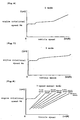
Fig. 6 : A transmission characteristic graph in a D mode of the automatic transmission control device according to one embodiment of the present invention. -
Fig. 7 : A transmission characteristic graph in an S mode of the automatic transmission control device according to one embodiment of the present invention. -
Fig. 8 : A transmission characteristic graph in an M mode of the automatic transmission control device according to one embodiment of the present invention. -
Fig. 9 : A flow chart showing steps of a shift-down determination control according to one embodiment of the present invention. -
Fig. 10 : A data table showing the relationship between the deceleration and a shift-down ΔNe. -
Fig. 11 : A graph showing one example of the relationship between an engine rotational speed and a shift-down period at the time of deceleration. -
Fig. 12 . A graph showing one example of the relationship between the engine rotational speed and the shift-down period at the time of deceleration. -
Fig. 13 : A graph showing one example of the relationship between the engine rotational speed and the shift-down period at the time of deceleration. - Hereinafter, a preferred embodiment of the present invention is explained in detail in conjunction with drawings.
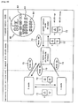
Fig. 1 is a cross-sectional view of a power unit of a scooter-type motorcycle which adopts an automatic transmission control device according to an embodiment of the present invention. A unit-swingtype power unit 1 which is integrally constituted of an engine and a continuously variable transmission which transmits a driving force of the engine to a driving wheel at a proper gear ratio is, assuming the lateral direction in the drawing as the vehicle width direction, connected to a pivot portion arranged on a rear portion of the scooter-type motorcycle in a rockable manner. Apiston 6 is connected to acrankshaft 13 which constitutes an output shaft of the engine by way of a connectingrod 12, and thepiston 6 is slidably arranged in the inside of acylinder 11 which is mounted in acylinder block 10. Acylinder head 7 is fixed to an upper end of thecylinder block 10, and acombustion chamber 8 in which air-fuel mixture is burnt is formed of thecylinder head 7, thecylinder 11 and thepiston 6. - In the
cylinder head 7, a valve (not shown in the drawing) which controls an intake and an exhaust of the air-fuel mixture to and from the combustion chamber and anignition plug 5 which ignites the compressed air-fuel mixture are arranged. An open/close operation of the valve is controlled by the rotation of acam shaft 3 which is pivotally supported on thecylinder head 7. A driven sprocket wheel 4 is provided to a right end portion of thecam shaft 3 above which a cylinder head cover 2 is arranged, and anendless cam chain 9 is extended between and is wound around the driven sprocket wheel 4 and adrive sprocket wheel 36 which is mounted on thecrankshaft 13. - An ACG
starter motor 29 which is fixed to a right end portion of thecrankshaft 13 is accommodated in a right end portion of thecrank case 14 which pivotally supports thecrankshaft 13. In the vicinity of the ACGstarter motor 29, anNe sensor 30 which constitutes an engine rotational speed detection means for detecting a rotational speed of the engine based on a rotational speed of theACG starter motor 29 is provided. On one hand, a continuouslyvariable transmission 37 which is constituted of a drive-side pulley 38, aV belt 19 and a driven-side pulley 39 is connected to a left side of thecrankshaft 13 in the drawing. Here, afan 18 which is rotated in synchronism with thecrankshaft 13 and forcibly cools the continuouslyvariable transmission 37 and the like is formed on the drive-side pulley 38. The continuouslyvariable transmission 37 is a continuously variable-transmission belt converter which is constituted by extending the endless-type V belt 19 between the drive-side pulley 38 which is connected to a left end portion of thecrankshaft 13 and a driven-side pulley 39 which is mounted on adrive shaft 27 which is pivotally supported on atransmission case 15 and is arranged in parallel to thecrankshaft 13 by way of astart clutch 26. The continuouslyvariable transmission 37 according to this embodiment includes a gearratio control motor 22 for arbitrarily changing a gear ratio in the vicinity of the drive-side pulley 38. - The drive-
side pulley 38 includes a drive-side fixedpulley half body 16 which is fixed to a left end portion of thecrankshaft 13 and a drive-side movablepulley half body 17 which is slidably mounted on thecrankshaft 13 in the axial direction of thecrank shaft 13. In the drawing, the drive-side movable pulleyhalf body 17 is provided with a feed screw on a right side thereof. By rotating the drive-side movablepulley half body 17 with a driving force of the gearratio control motor 22 which is transmitted by way of apinion gear 23, afirst transmission gear 24 and asecond transmission gear 25, the drive-side movablepulley half body 17 is slidably movable in the axial direction of thecrankshaft 13. Here, in the vicinity of the drive-side movable pulleyhalf body 17, agear ratio sensor 31 which can detect a gear ratio by detecting a position of the drive-side movable pulleyhalf body 17 is provided. - On the other hand, the driven-
side pulley 39 includes a driven-side fixed pulleyhalf body 20 which is fixed to asleeve 55 integrally rotated with a rotor which supports aclutch shoe 57 of thestart clutch 26 and a driven-side movable pulleyhalf body 21 which is slidably movable in the axial direction of thesleeve 55. Further, theV belt 19 is extended between and is wound around substantially V-shaped cross-section belt grooves which are respectively formed between the drive-side fixedpulley half body 16 and the drive-side movable pulleyhalf body 17 and between the driven-side fixed pulleyhalf body 20 and the driven-side movable pulleyhalf body 21. Further, on a back side of the driven-side movable pulleyhalf body 21, aspring 21a which always biases the driven-side movable pulleyhalf body 21 toward the driven-side fixed pulleyhalf body 20 is provided. - The start clutch 26 interrupts, when a rotational speed of the driven-
side pulley 39 does not reach a predetermined value, the transmission of a driving force between the driven-side pulley 39 and thedrive shaft 27. Then, when the rotational speed of the engine is increased and the rotational speed of the driven-side pulley 39 becomes the predetermined value or more, theclutch shoe 57 pushes an inner peripheral surface of anouter case 56 by a centrifugal force. Accordingly, the rotation of the driven-side pulley 39 is transmitted to theouter case 56 by way of thesleeve 55 and theclutch shoe 57 and hence, thedrive shaft 27 which is fixed to theouter case 56, apower transmitting shaft 28 which is meshed with thedrive shaft 27, and an axle (not shown in the drawing) of a drive wheel which is meshed with the transmittingshaft 28 are rotated. Here, in the vicinity of theouter case 56, avehicle speed sensor 32 which detects a vehicle speed based on the rotational speed of theouter case 56 is provided. - The shift of the gear ratio of the continuously
variable transmission 37 is performed by rotatably driving the gearratio control motor 22 in the direction corresponding to up/down shifting of the gear ratio. When the rotational direction of the gearratio control motor 22 is directed in the shift-up direction (top ratio direction), the drive-side movablepulley half body 17 is allowed to slide in the left direction in the drawing. Then, when the drive-side movable pulleyhalf body 17 approaches the drive-side fixedpulley half body 16 by an amount corresponding to the sliding of the drive-side movable pulleyhalf body 17, the belt groove width of the drive-side pulley 38 is decreased. Accordingly, a contact position between the drive-side pulley 38 and theV belt 19 is shifted in the radially outward direction and hence, a wrapping diameter of theV belt 19 is increased (in the drawing, a low ratio position 17 (L) shown above thecrankshaft 13 and a top ratio position (H) shown below the crankshaft 13). - Along with the above-mentioned gear change operation, in the driven-
side pulley 39, a distance between thecrankshaft 13 and thedrive shaft 27 is unchanged and theV belt 19 is an endless belt and hence, a force which tends to reduce the wrapping diameter acts. Accordingly, the driven-side movablepulley half body 21 slides in the leftward direction in the drawing against a resilient force which aspring 21 a biases, and a groove width which is defined by the driven-side fixedpulley half body 20 and the driven-side movablepulley half body 21 is increased. In this manner, the change of the gear ratio of the continuouslyvariable transmission 37 is realized by continuously changing the wrapping diameter (power transmission pitch diameter) of theV belt 19. - As described above, the continuously
variable transmission 37 according to this embodiment can steplessly select an arbitrary gear ratio by controlling the gearratio control motor 22. Accordingly, depending on the manner of controlling the gearratio control motor 22, not to mention that the vehicle can travel smoothly based on the continuously variable transmission, by setting a plurality of fixed gear ratios (for example, 7 steps), it is possible to perform a manual-transmission gear change control in which a rider can carry out the shift change between fixed gear ratios as well as a gear change control which allows the rider to obtain the riding feeling such as a manual-auto-shifting motorcycle in which an automatic gear change is performed in a stepped transmission. -
Fig. 2 is a block diagram showing the constitution of the automatic transmission control device according to an embodiment of the present invention. Thebattery 35 which is mounted on the motorcycle supplies electricity or power to acontrol unit 50 which is mounted on an arbitrary portion of the motorcycle and the gearratio control motor 22. The power which drives the gearratio control motor 22 is controlled and supplied by thecontrol unit 50. When anignition SW 71 which constitutes a main switch is turned on, thecontrol unit 50 is started. Thecontrol unit 50 gives command signals to the gearratio control motor 22 based on information supplied from thegear ratio sensor 31, theNe sensor 30, thevehicle speed sensor 32 and aTh opening sensor 33 which detects an opening of a throttle valve (not shown in the drawing) which are arranged in thepower unit 1. In the inside of thecontrol unit 50, a gear changetiming control part 51 which includes a shift-downrestriction timer 51a and a shift-downNe setting part 51b is provided. Here, contents of the command signals are also changed corresponding to a manipulation state of ashift SW 72 which constitutes a switch for manually performing the shift change, and amode SW 73 which changes over a gear change mode of the automatic transmission device. Details of the shift change and the gear change modes in this embodiment are described later. -
Fig. 3 is a perspective view of a left handle switch which is adopted by the motorcycle according to the embodiment of the present invention. On a left portion of a pipe-like handle 47 in the drawing, aleft handle grip 45 is mounted, while in front of thehandle 47 in the longitudinal direction of the vehicle, aleft brake lever 46 is arranged. Further, between theleft handle grip 45 and a brakefluid reservoir tank 44, aleft switch case 40 is arranged. On theleft switch case 40, ablinker switch 42, ahorn switch 43, an opticalaxis selector switch 41 of a head light, and theshift SW 72 which rocks in the plus direction (+) as well as in the minus direction (-) like a seesaw from a neutral state are mounted. -
Fig. 4 is a perspective view of a right handle switch which is adopted by the motorcycle according to this embodiment of the present invention. InFig. 4 , a state as viewed from a front side of the vehicle is shown. On the right handle which is integrally formed with thehandle 47, aright handle grip 61 is mounted, and aright switch case 60 is arranged in the vicinity of aright brake lever 62. On the right-side switch case 60, akill switch 63 which stops the engine in emergency, and amode SW 73 which is manipulated by a forefinger of rider's right hand are provided. -
Fig. 5 is a schematic explanatory view of a gear change mode switching of the transmission control device according to one embodiment of the present invention. As described above, in this embodiment, a "continuously variable gear change mode" in which a mode is selected from two kinds of modes consisting of a D mode which emphasizes a fuel consumption performance and an S mode which emphasizes an accelerating performance, a "7-gear manual transmission mode" in which the gear ratio is changed over out of arbitrarily set seven gear steps by a rider's instruction and a "7-gear automatic shift mode" which provides the riding feeling as if the automatic transmission is performed using the 7-steps transmission are prepared. With respect to a switching manipulation of the respective gear change modes, the switching between the D mode and the S mode is performed using theshift SW 72. When themode SW 73 is pushed from the D mode or the S mode state, it is possible to change over the mode to the 7-gear automatic shift mode (A mode). Further, when the either one of "up" or "down" of theshift SW 72 is pushed in the A mode state, the A mode is changed over to the 7-gear manual shift mode (M mode). In the M mode, the 7-step gear change manipulation can be performed arbitrarily using theshift SW 72. Further, when themode SW 73 is pushed from the M mode, the M mode is changed over to the A mode. Further, when themode SW 73 is pushed, the A mode is changed over to the D mode. - To allow the rider to confirm the switching states of the respective gear change modes, for example, the switching state is displayed in a
display part 80 which is arranged in the inside of a meter panel. In thedisplay part 80, a gearchange mode indicator 82 which indicates the switching state of the respective gear change modes based on lightning of a lamp is arranged above aclock display portion 84 and atrip meter 83. Further, above the gearchange mode indicator 82, ashift indicator 81 which displays the present gear step change in the M mode or in the A mode is arranged. Here, theshift indicator 81 is also used as a fuel consumption meter which indicates fuel consumption in a predetermined section. -
Fig. 6 to Fig. 8 show one example of transmission characteristic graphs in the above-mentioned D mode, S mode and M mode. Compared to the D mode (Fig. 6 ) which shifts a gear ratio in the top ratio direction in a state that the engine rotational speed is relatively low by taking the fuel consumption performance into consideration, in the S mode (Fig. 7 ) which requires sharp traveling, the gear ratio is set such that the engine rotational speed Ne is held at a high state as a whole. Further, in the M mode (Fig. 8 ), fixed gear ratios are set in the same manner as the usual stepped transmission. In the above-mentioned 7-step auto shift mode (A mode), between fixed gear ratios which are applied to the M mode, the gear ratio is set such that the shift change is automatically performed. - Here, inventors of the present invention focus on the shift-down control when the deceleration is performed with a deceleration brake during traveling in the above-mentioned A mode. Irrespective of the map of the gear change timing at the time of usual traveling, in the conventional automatic transmission control device which determines the timing of the shift-down based on the deceleration and the vehicle speed, the engine rotational speed is not taken into consideration. Accordingly, there exist possibilities which adversely affect the riding feeling including a possibility that when the deceleration is large, the engine rotational speed is increased after the shift-down so that a gear-change shock is increased. To overcome this drawback, the automatic transmission control device of this embodiment is characterized in that the shift-down can be performed at proper timing by taking a value of the engine rotational speed which performs the shift-down into consideration in addition to the deceleration. Next, the shift-down timing determination control which is applied to the automatic transmission control device according to one embodiment of the present invention is explained in detail in conjunction with the flow chart shown in
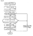
Fig. 9 . -
Fig. 9 is a flow chart showing steps of the shift-down timing determination control according to one embodiment of the present invention which acontrol unit 50 applies to the gearratio control motor 22 shown inFig. 2 . The flow chart is repeatedly executed at a predetermined cycle. First of all, in step S10, a peak Ne is measured. The peak Ne as a peak value is the maximum engine rotational speed which is recorded in the gear step during a period from the changeover to the present gear step to a point of time of measurement. The peak Ne is induced by arithmetic processing which is executed in the inside of a gear changetiming control part 51 based on information from theNe sensor 30 and thegear ratio sensor 31, and is stored in a shift-downNe setting part 51b which constitutes a peak value storing means. Further, leveling processing is applied to an output value from theNe sensor 30 for avoiding the influence of external noises. - In succeeding
step S 11, the deceleration of the motorcycle is measured based on the information from thevehicle speed sensor 32 which constitutes the deceleration detecting means. Next, instep S 12, it is determined whether the shift-downrestriction timer 51 a is being operated or not. When it is determined that the shift-downrestriction timer 51a is being operated instep S 12, the processing advances to stepS 13 and a shift-down restriction command is executed. The manner of operation of the shift-downrestriction timer 51 a is explained later. - Next, in step S14, the shift-down ΔNe is read out. The shift-down ΔNe is a numerical value which is induced from a deceleration-shift-down ΔNe table which is accommodated in the shift-down
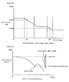
Ne setting part 51b. As exemplified by an example shown inFig. 10 , the shift-down ΔNe is determined such that the larger the deceleration at the time of measurement, the shift-down ΔNe becomes smaller. Also in the example shown inFig. 10 , it is confirmed that the ΔNe2 which is a value of the shift-down ΔNe when the vehicle speed is decelerated at the deceleration g2 is smaller than the ΔNe which is a value of the shift-down ΔNe when the vehicle speed is decelerated at the deceleration g1. - In succeeding
step S 15, it is determined whether the present engine rotational speed Ne assumes a value which is obtained by subtracting the shift-down ΔNe from the peak Ne or less or not and, at the same time, whether the throttle opening Th assumes a predetermined value or less or not. Here, in conjunction withFig. 11 , the detail of the determination in step S15 is explained. First of all, the peak Ne during traveling at a certain gear step is always measured and updated. Then, when the deceleration starts, the shift-down ΔNe which corresponds to the deceleration is induced and hence, the shift-down executed Ne is calculated using a calculation formula (peak Ne - shift-down ΔNe). In the example shown in the drawing, since the deceleration is g1; ΔNe1 is induced as the shift-down ΔNe. As described above, the determination instep S 15 is the determination whether the present engine rotational speed Ne becomes a value equal to or less than the shift-down executed Ne or not and, at the same time, whether throttle opening becomes a value equal to or less than the predetermined value or not. Accordingly, the larger the deceleration of the vehicle, the value of the shift-down ΔNe becomes smaller and, corresponding to the decrease of the shift-down ΔNe, the engine rotational speed Ne (the shift-down executed Ne) on which the gear changetiming control part 51 executes the shift-down is increased. -
Fig. 12 is a schematic view of the shift-down operation when the deceleration of the vehicle is larger than the deceleration of the vehicle in the example shown inFig. 11 . In the example shown in the drawing, the shift-down ΔNe is ΔNe2 which is induced from g2 which is larger than g1. According to this drawing, it is confirmed that the larger the value of the deceleration, the shift-down is performed at a point of time that the lowering width (ΔNe) from the peak Ne is small, that is, with the shift-down executed Ne in a state that the engine rotational speed is relatively high. Accordingly, at the time of rapid deceleration, the shift-down is quickly performed while maintaining the high engine rotational speed and hence, even when the reacceleration is performed immediately after the rapid deceleration, it is possible to prevent a phenomenon that that the engine rotational speed is excessively lowered so that a sufficient acceleration force cannot be obtained. Here, the determination whether the throttle opening Th becomes a value equal or less than the predetermined value or not which is included instep S 15 is performed for determining whether a rider has a clear intention of decelerating the vehicle speed. - Returning to the flow chart shown in
Fig. 9 , when the determination in step S15 is satisfied, the processing advances to step S16 and the counting by the shift-downrestriction timer 51 a is started. The shift-downrestriction timer 51a is provided for restricting the shift-down during a predetermined period and a count time thereof is set to 0.5 second, for example. Then, when the counting by the shift-downrestriction timer 51 a is finished in succeedingstep S 17, the shift-down by one speed is performed. Here, the processing insteps Fig. 13 . In the drawing, time (t) which satisfies the determination in step S15 is time t1 that the engine rotational speed reaches the shift-down executed Ne. When the time t1 comes, along with the start of the counting by the shift-downrestriction timer 51a, the shift down restricting period is started (step S16). Then, at a point of time that the predetermined restricting period up to time t2 elapses, the shift-down by one speed is performed (step S17). - Here, when the shift-down control is performed based on only the shift-down ΔNe without using the above-mentioned shift-down
restriction timer 51a, the larger the deceleration of the motorcycle, the shift-down is performed with the engine rotational speed having the smaller lowering width from the peak Ne. Accordingly, during the execution of this shift-down control, when the large deceleration is continuously applied, the shift-down is continuously performed thus excessively increasing the engine rotational speed or increasing the transmission shock along with such an increase of the engine rotational speed whereby there arises a possibility that the riding feeling is adversely affected. A portion indicated by a broken line inFig. 13 shows a case in which when the shift-down restricting control is not performed, the shift-down is performed at the time t1 and the engine rotational speed after the shift-down is increased. - However, in this embodiment, the timing of the shift down is slightly delayed by providing the shift-down
restriction timer 51 a, the shift-down is performed as indicated by a solid line inFig. 13 whereby it is possible to cope with the above-mentioned drawback. - As described above, according to the automatic transmission control device of the present invention, by setting the shift-down ΔNe corresponding to the deceleration and by performing the shift-down at a point of time that the engine rotational speed is lowered from the peak Ne by the shift-down ΔNe, it is possible to perform the shift-down at the timing which takes not only the deceleration but also the engine rotational speed into consideration. Further, the engine rotational speed is configured such that the larger the deceleration, the shift-down ΔNe becomes smaller and hence, the larger the deceleration, the shift-down can be performed with the engine rotational speed having the small lowering width from the peak Ne. That is, the shift-down can be quickly performed while maintaining the high engine rotational speed and hence, even when the reacceleration is performed immediately after the rapid deceleration, it is possible to prevent a phenomenon that the engine rotational speed is excessively lowered so that a sufficient acceleration force cannot be obtained. Further, the shift-down can be restricted during the predetermined period by providing the shift-down restriction timer, it is possible to prevent a phenomenon that the shift-down is continuously performed at the time of the rapid deceleration thus increasing the transmission shock.
- Here, it is needless to say that the data table which indicates the relationship between the deceleration and the shift-down ΔNe, the manner of setting the shift-down restricting period and the like are not limited to the above-mentioned embodiments and various modifications are conceivable.
- 1: power unit, 6: piston, 12: connecting rod, 13: crankshaft, 16: drive-side fixed pulley half body, 17: drive-side movable pulley half body, 19: V belt, 20: driven-side fixed pulley half body, 21: driven-side movable pulley half body, 22: gear ratio control motor, 30: Ne sensor, 31: gear ratio sensor, 32: vehicle speed sensor, 37: continuously variable transmission, 38: drive-side pulley, 39: driven-side pulley
Claims (5)
- An automatic transmission control device which performs a gear, change operation based on deceleration of a vehicle body, the automatic transmission control device comprising:a deceleration detecting means (32) which detects the deceleration; andan engine rotational speed detecting means (30) which detects an engine rotational speed;characterized bya peak value storing means (51b) which stores a peak value of the engine rotational speed (Ne) during a period in which a vehicle travels with one predetermined gear step;a map which shows the relationship between the deceleration and a shift-down rotational speed; anda means which performs a shift-down when the engine rotational speed (Ne) is lowered from the peak value by a predetermined rotational speed which is obtained from the map based on the deceleration.
- An automatic transmission control device according to claim 1, wherein the means which performs the shift-down performs the shift-down toward a low speed side by one step when the engine rotational speed (Ne) is lowered from the peak value by the predetermined rotational speed.
- An automatic transmission control device according to claim 1 or claim 2, wherein the predetermined rotational speed is set to a smaller value corresponding to the increase of the deceleration.
- An automatic transmission control device according to any one of claims 1 to 3, wherein the means which performs the shift-down operates a timer (51a) which restricts the shift-down for a predetermined period when the engine rotational speed (Ne) is lowered from the peak value by the predetermined rotational speed, and performs the shift-down at a point of time that the timer (51a) finishes.
- An automatic transmission control device according to any one of claims 1 to 4, wherein the automatic transmission control device is used for a motorcycle.
Applications Claiming Priority (1)
| Application Number | Priority Date | Filing Date | Title |
|---|---|---|---|
| JP2005276538A JP4817228B2 (en) | 2005-09-22 | 2005-09-22 | Automatic transmission control device |
Publications (2)
| Publication Number | Publication Date |
|---|---|
| EP1767827A1 EP1767827A1 (en) | 2007-03-28 |
| EP1767827B1 true EP1767827B1 (en) | 2008-03-19 |
Family
ID=36952633
Family Applications (1)
| Application Number | Title | Priority Date | Filing Date |
|---|---|---|---|
| EP06016111A Expired - Fee Related EP1767827B1 (en) | 2005-09-22 | 2006-08-02 | Automatic transmission control device |
Country Status (7)
| Country | Link |
|---|---|
| US (1) | US7470213B2 (en) |
| EP (1) | EP1767827B1 (en) |
| JP (1) | JP4817228B2 (en) |
| CN (1) | CN100436887C (en) |
| DE (1) | DE602006000757T2 (en) |
| ES (1) | ES2302559T3 (en) |
| TW (1) | TW200722660A (en) |
Families Citing this family (22)
| Publication number | Priority date | Publication date | Assignee | Title |
|---|---|---|---|---|
| JP5161523B2 (en) * | 2007-03-30 | 2013-03-13 | ヤマハ発動機株式会社 | Saddle type vehicle, power unit and continuously variable transmission |
| US8088037B2 (en) | 2007-03-30 | 2012-01-03 | Yamaha Hatsudoki Kabushiki Kaisha | Straddle type vehicle, power unit and continuously variable transmission |
| JP4879149B2 (en) * | 2007-09-07 | 2012-02-22 | 本田技研工業株式会社 | V belt type continuously variable transmission |
| JP5071438B2 (en) * | 2009-05-19 | 2012-11-14 | トヨタ自動車株式会社 | Control device for vehicle power transmission device |
| JP2011047511A (en) * | 2009-08-28 | 2011-03-10 | Yamaha Motor Co Ltd | Multiple clutch transmission control apparatus and multiple clutch transmission control method |
| CN101943262B (en) * | 2010-09-30 | 2013-06-19 | 重庆长安汽车股份有限公司 | Sudden step-on-accelerator control method for automatic transmission |
| CN102102757A (en) * | 2011-03-21 | 2011-06-22 | 重庆长安汽车股份有限公司 | Method for upshifting or downshifting delay control of AT (Automatic Transmission) |
| CN102537312B (en) * | 2011-12-31 | 2015-04-01 | 重庆长安汽车股份有限公司 | Method for controlling automatic transmission to downshift after braking |
| JP2014065326A (en) * | 2012-09-24 | 2014-04-17 | Showa Corp | Vehicle height control system |
| US8996261B2 (en) | 2012-10-25 | 2015-03-31 | Toyota Motor Engineering & Manufacturing North America, Inc. | Automobile paddle shifters locking device and system |
| US8996260B2 (en) | 2012-10-25 | 2015-03-31 | Toyota Motor Engineering & Manufacturing North America, Inc. | Automobile paddle shifters with first and second positions |
| US9002597B2 (en) | 2012-10-26 | 2015-04-07 | Toyota Motor Engineering & Manufacturing North America, Inc. | Automobile paddle shifters with secondary paddles |
| US8545368B1 (en) * | 2012-11-01 | 2013-10-01 | Caterpillar Inc. | Regulation of a machine with a continuously variable transmission and service brakes |
| US8788166B1 (en) * | 2013-02-28 | 2014-07-22 | Ford Global Technologies, Llc | Downshift controls using measured output torque |
| JP5914444B2 (en) * | 2013-09-30 | 2016-05-11 | 本田技研工業株式会社 | Vehicle transmission |
| US9759313B2 (en) | 2014-11-26 | 2017-09-12 | Polaris Industries Inc. | Electronic shifting of a transmission |
| US9746070B2 (en) | 2014-11-26 | 2017-08-29 | Polaris Industries Inc. | Electronic control of a transmission |
| DE102015203899A1 (en) * | 2015-03-05 | 2016-09-08 | Robert Bosch Gmbh | CVT transmission with improved controllability |
| DE102015203913A1 (en) * | 2015-03-05 | 2016-09-08 | Robert Bosch Gmbh | CVT transmission with improved controllability |
| DE102015203901A1 (en) * | 2015-03-05 | 2016-09-08 | Robert Bosch Gmbh | CVT transmission with improved controllability |
| TWI636917B (en) * | 2017-05-09 | 2018-10-01 | 摩特動力工業股份有限公司 | ECVT (electronic stepless speed change) system and control method thereof |
| US11460103B2 (en) * | 2018-01-23 | 2022-10-04 | Jatco Ltd | Lock-up disengagement control device for automatic transmission |
Family Cites Families (14)
| Publication number | Priority date | Publication date | Assignee | Title |
|---|---|---|---|---|
| JPH0217258A (en) * | 1988-07-06 | 1990-01-22 | Nissan Motor Co Ltd | Automatic engine brake control device for automatic transmission |
| JP2913481B2 (en) * | 1989-05-19 | 1999-06-28 | アイシン精機株式会社 | Hydraulic control device for automatic transmission |
| US5136897A (en) * | 1991-05-09 | 1992-08-11 | Eaton Corporation | Smooth upshift control method/system |
| DE4120603C2 (en) * | 1991-06-21 | 1995-11-09 | Porsche Ag | Control device for an automatically shifting transmission of a motor vehicle |
| US5335566A (en) * | 1992-07-06 | 1994-08-09 | Eaton Corporation | Shift control method/system |
| JPH08113181A (en) * | 1994-10-14 | 1996-05-07 | Akebono Brake Ind Co Ltd | Bicycle with automatic transmission |
| JP3508313B2 (en) | 1995-07-25 | 2004-03-22 | マツダ株式会社 | Control device for automatic transmission |
| JP3631563B2 (en) * | 1996-09-04 | 2005-03-23 | トヨタ自動車株式会社 | Driving orientation estimation device for vehicle |
| FR2765652B1 (en) * | 1997-07-02 | 1999-09-03 | Renault | METHOD FOR MONITORING THE PHASES OF RETROGRADING OF AUTOMATIC TRANSMISSIONS |
| JP3709954B2 (en) * | 1997-09-13 | 2005-10-26 | 本田技研工業株式会社 | Electric transmission and its shift control method |
| GB9720172D0 (en) * | 1997-09-24 | 1997-11-26 | Rover Group | A transmission control system for a vehicle |
| JP4515564B2 (en) * | 1999-11-08 | 2010-08-04 | アイシン・エーアイ株式会社 | Shift automatic return device in automatic transmission |
| JP4310059B2 (en) * | 2001-12-05 | 2009-08-05 | 富士重工業株式会社 | Transmission control device for transmission |
| US7212898B2 (en) * | 2005-02-09 | 2007-05-01 | General Motors Corporation | Method and apparatus for adaptive control of power-on skip through neutral downshifts |
-
2005
- 2005-09-22 JP JP2005276538A patent/JP4817228B2/en active Active
-
2006
- 2006-08-02 ES ES06016111T patent/ES2302559T3/en active Active
- 2006-08-02 EP EP06016111A patent/EP1767827B1/en not_active Expired - Fee Related
- 2006-08-02 DE DE602006000757T patent/DE602006000757T2/en active Active
- 2006-09-11 TW TW095133450A patent/TW200722660A/en not_active IP Right Cessation
- 2006-09-19 CN CNB2006101388359A patent/CN100436887C/en not_active Expired - Fee Related
- 2006-09-19 US US11/533,099 patent/US7470213B2/en not_active Expired - Fee Related
Also Published As
| Publication number | Publication date |
|---|---|
| JP2007085491A (en) | 2007-04-05 |
| CN1936373A (en) | 2007-03-28 |
| US7470213B2 (en) | 2008-12-30 |
| EP1767827A1 (en) | 2007-03-28 |
| CN100436887C (en) | 2008-11-26 |
| JP4817228B2 (en) | 2011-11-16 |
| TW200722660A (en) | 2007-06-16 |
| ES2302559T3 (en) | 2008-07-16 |
| US20070066444A1 (en) | 2007-03-22 |
| DE602006000757D1 (en) | 2008-04-30 |
| DE602006000757T2 (en) | 2009-04-09 |
| TWI312042B (en) | 2009-07-11 |
Similar Documents
| Publication | Publication Date | Title |
|---|---|---|
| EP1767827B1 (en) | Automatic transmission control device | |
| US7578767B2 (en) | Automatic transmission control device | |
| EP1985894B1 (en) | Control device for an automatic vehicle transmission | |
| US7641016B2 (en) | Straddle-type vehicle | |
| EP2687705B1 (en) | Engine control apparatus, and engine control method | |
| JP5055070B2 (en) | Continuously variable transmission and saddle riding type vehicle | |
| EP2123530A2 (en) | Device and method for controlling transmission mechanism, and method for controlling motor vehicle | |
| JP5246676B2 (en) | Shift map switching control device | |
| JP2008164077A (en) | Shift map switching control device | |
| JP6913607B2 (en) | Vehicle with auto downshift function | |
| JP5226285B2 (en) | Saddle-type vehicle control device, transmission, and saddle-type vehicle | |
| JP5161523B2 (en) | Saddle type vehicle, power unit and continuously variable transmission | |
| JP4998736B2 (en) | Automatic transmission control device for motorcycle | |
| JP5003899B2 (en) | Automatic transmission control device for motorcycle | |
| JP5003898B2 (en) | Automatic transmission control device for motorcycle | |
| EP1975474B1 (en) | Continuously variable transmission | |
| JP6106485B2 (en) | Control device for continuously variable transmission |
Legal Events
| Date | Code | Title | Description |
|---|---|---|---|
| PUAI | Public reference made under article 153(3) epc to a published international application that has entered the european phase |
Free format text: ORIGINAL CODE: 0009012 |
|
| 17P | Request for examination filed |
Effective date: 20060802 |
|
| AK | Designated contracting states |
Kind code of ref document: A1 Designated state(s): AT BE BG CH CY CZ DE DK EE ES FI FR GB GR HU IE IS IT LI LT LU LV MC NL PL PT RO SE SI SK TR |
|
| AX | Request for extension of the european patent |
Extension state: AL BA HR MK YU |
|
| 17Q | First examination report despatched |
Effective date: 20070504 |
|
| GRAP | Despatch of communication of intention to grant a patent |
Free format text: ORIGINAL CODE: EPIDOSNIGR1 |
|
| GRAS | Grant fee paid |
Free format text: ORIGINAL CODE: EPIDOSNIGR3 |
|
| AKX | Designation fees paid |
Designated state(s): DE ES FR IT |
|
| GRAA | (expected) grant |
Free format text: ORIGINAL CODE: 0009210 |
|
| AK | Designated contracting states |
Kind code of ref document: B1 Designated state(s): DE ES FR IT |
|
| REF | Corresponds to: |
Ref document number: 602006000757 Country of ref document: DE Date of ref document: 20080430 Kind code of ref document: P |
|
| REG | Reference to a national code |
Ref country code: ES Ref legal event code: FG2A Ref document number: 2302559 Country of ref document: ES Kind code of ref document: T3 |
|
| ET | Fr: translation filed | ||
| PLBE | No opposition filed within time limit |
Free format text: ORIGINAL CODE: 0009261 |
|
| STAA | Information on the status of an ep patent application or granted ep patent |
Free format text: STATUS: NO OPPOSITION FILED WITHIN TIME LIMIT |
|
| 26N | No opposition filed |
Effective date: 20081222 |
|
| REG | Reference to a national code |
Ref country code: DE Ref legal event code: R084 Ref document number: 602006000757 Country of ref document: DE |
|
| REG | Reference to a national code |
Ref country code: DE Ref legal event code: R084 Ref document number: 602006000757 Country of ref document: DE Effective date: 20150505 |
|
| PGFP | Annual fee paid to national office [announced via postgrant information from national office to epo] |
Ref country code: DE Payment date: 20150729 Year of fee payment: 10 |
|
| REG | Reference to a national code |
Ref country code: FR Ref legal event code: PLFP Year of fee payment: 11 |
|
| REG | Reference to a national code |
Ref country code: DE Ref legal event code: R119 Ref document number: 602006000757 Country of ref document: DE |
|
| REG | Reference to a national code |
Ref country code: FR Ref legal event code: PLFP Year of fee payment: 12 |
|
| PG25 | Lapsed in a contracting state [announced via postgrant information from national office to epo] |
Ref country code: DE Free format text: LAPSE BECAUSE OF NON-PAYMENT OF DUE FEES Effective date: 20170301 |
|
| PGFP | Annual fee paid to national office [announced via postgrant information from national office to epo] |
Ref country code: FR Payment date: 20170628 Year of fee payment: 12 |
|
| PGFP | Annual fee paid to national office [announced via postgrant information from national office to epo] |
Ref country code: CH Payment date: 20170724 Year of fee payment: 12 |
|
| PGFP | Annual fee paid to national office [announced via postgrant information from national office to epo] |
Ref country code: IT Payment date: 20180823 Year of fee payment: 13 |
|
| PG25 | Lapsed in a contracting state [announced via postgrant information from national office to epo] |
Ref country code: FR Free format text: LAPSE BECAUSE OF NON-PAYMENT OF DUE FEES Effective date: 20180831 |
|
| REG | Reference to a national code |
Ref country code: ES Ref legal event code: FD2A Effective date: 20190918 |
|
| PG25 | Lapsed in a contracting state [announced via postgrant information from national office to epo] |
Ref country code: ES Free format text: LAPSE BECAUSE OF NON-PAYMENT OF DUE FEES Effective date: 20180803 |
|
| PG25 | Lapsed in a contracting state [announced via postgrant information from national office to epo] |
Ref country code: IT Free format text: LAPSE BECAUSE OF NON-PAYMENT OF DUE FEES Effective date: 20190802 |