EP1767174A2 - Iris recognition and tracking for optical treatment - Google Patents
Iris recognition and tracking for optical treatment Download PDFInfo
- Publication number
- EP1767174A2 EP1767174A2 EP06020056A EP06020056A EP1767174A2 EP 1767174 A2 EP1767174 A2 EP 1767174A2 EP 06020056 A EP06020056 A EP 06020056A EP 06020056 A EP06020056 A EP 06020056A EP 1767174 A2 EP1767174 A2 EP 1767174A2
- Authority
- EP
- European Patent Office
- Prior art keywords
- eye
- refractive
- iris
- data
- image
- Prior art date
- Legal status (The legal status is an assumption and is not a legal conclusion. Google has not performed a legal analysis and makes no representation as to the accuracy of the status listed.)
- Ceased
Links
- IEGNECZFWJSUFM-UHFFFAOYSA-N CC(CC1(C)C)C(C)C1I Chemical compound CC(CC1(C)C)C(C)C1I IEGNECZFWJSUFM-UHFFFAOYSA-N 0.000 description 1
- 0 CCC(C)(CC1)C(C2)(C3(C)CC4)C56C33C7(C8)C55C(C)(C9)CCC(C)(CC)CC7C(CC7)C9(C)C*1(C)C27C68C43C5 Chemical compound CCC(C)(CC1)C(C2)(C3(C)CC4)C56C33C7(C8)C55C(C)(C9)CCC(C)(CC)CC7C(CC7)C9(C)C*1(C)C27C68C43C5 0.000 description 1
Images


Classifications
-
- A—HUMAN NECESSITIES
- A61—MEDICAL OR VETERINARY SCIENCE; HYGIENE
- A61F—FILTERS IMPLANTABLE INTO BLOOD VESSELS; PROSTHESES; DEVICES PROVIDING PATENCY TO, OR PREVENTING COLLAPSING OF, TUBULAR STRUCTURES OF THE BODY, e.g. STENTS; ORTHOPAEDIC, NURSING OR CONTRACEPTIVE DEVICES; FOMENTATION; TREATMENT OR PROTECTION OF EYES OR EARS; BANDAGES, DRESSINGS OR ABSORBENT PADS; FIRST-AID KITS
- A61F9/00—Methods or devices for treatment of the eyes; Devices for putting-in contact lenses; Devices to correct squinting; Apparatus to guide the blind; Protective devices for the eyes, carried on the body or in the hand
- A61F9/007—Methods or devices for eye surgery
- A61F9/008—Methods or devices for eye surgery using laser
- A61F9/00802—Methods or devices for eye surgery using laser for photoablation
- A61F9/00804—Refractive treatments
-
- A—HUMAN NECESSITIES
- A61—MEDICAL OR VETERINARY SCIENCE; HYGIENE
- A61B—DIAGNOSIS; SURGERY; IDENTIFICATION
- A61B5/00—Measuring for diagnostic purposes; Identification of persons
- A61B5/117—Identification of persons
-
- A—HUMAN NECESSITIES
- A61—MEDICAL OR VETERINARY SCIENCE; HYGIENE
- A61F—FILTERS IMPLANTABLE INTO BLOOD VESSELS; PROSTHESES; DEVICES PROVIDING PATENCY TO, OR PREVENTING COLLAPSING OF, TUBULAR STRUCTURES OF THE BODY, e.g. STENTS; ORTHOPAEDIC, NURSING OR CONTRACEPTIVE DEVICES; FOMENTATION; TREATMENT OR PROTECTION OF EYES OR EARS; BANDAGES, DRESSINGS OR ABSORBENT PADS; FIRST-AID KITS
- A61F9/00—Methods or devices for treatment of the eyes; Devices for putting-in contact lenses; Devices to correct squinting; Apparatus to guide the blind; Protective devices for the eyes, carried on the body or in the hand
- A61F9/007—Methods or devices for eye surgery
- A61F9/008—Methods or devices for eye surgery using laser
- A61F9/00802—Methods or devices for eye surgery using laser for photoablation
- A61F9/00804—Refractive treatments
- A61F9/00806—Correction of higher orders
-
- G—PHYSICS
- G06—COMPUTING; CALCULATING OR COUNTING
- G06V—IMAGE OR VIDEO RECOGNITION OR UNDERSTANDING
- G06V40/00—Recognition of biometric, human-related or animal-related patterns in image or video data
- G06V40/10—Human or animal bodies, e.g. vehicle occupants or pedestrians; Body parts, e.g. hands
- G06V40/18—Eye characteristics, e.g. of the iris
-
- A—HUMAN NECESSITIES
- A61—MEDICAL OR VETERINARY SCIENCE; HYGIENE
- A61F—FILTERS IMPLANTABLE INTO BLOOD VESSELS; PROSTHESES; DEVICES PROVIDING PATENCY TO, OR PREVENTING COLLAPSING OF, TUBULAR STRUCTURES OF THE BODY, e.g. STENTS; ORTHOPAEDIC, NURSING OR CONTRACEPTIVE DEVICES; FOMENTATION; TREATMENT OR PROTECTION OF EYES OR EARS; BANDAGES, DRESSINGS OR ABSORBENT PADS; FIRST-AID KITS
- A61F9/00—Methods or devices for treatment of the eyes; Devices for putting-in contact lenses; Devices to correct squinting; Apparatus to guide the blind; Protective devices for the eyes, carried on the body or in the hand
- A61F9/007—Methods or devices for eye surgery
- A61F9/008—Methods or devices for eye surgery using laser
- A61F2009/00844—Feedback systems
- A61F2009/00846—Eyetracking
-
- A—HUMAN NECESSITIES
- A61—MEDICAL OR VETERINARY SCIENCE; HYGIENE
- A61F—FILTERS IMPLANTABLE INTO BLOOD VESSELS; PROSTHESES; DEVICES PROVIDING PATENCY TO, OR PREVENTING COLLAPSING OF, TUBULAR STRUCTURES OF THE BODY, e.g. STENTS; ORTHOPAEDIC, NURSING OR CONTRACEPTIVE DEVICES; FOMENTATION; TREATMENT OR PROTECTION OF EYES OR EARS; BANDAGES, DRESSINGS OR ABSORBENT PADS; FIRST-AID KITS
- A61F9/00—Methods or devices for treatment of the eyes; Devices for putting-in contact lenses; Devices to correct squinting; Apparatus to guide the blind; Protective devices for the eyes, carried on the body or in the hand
- A61F9/007—Methods or devices for eye surgery
- A61F9/008—Methods or devices for eye surgery using laser
- A61F2009/00844—Feedback systems
- A61F2009/00848—Feedback systems based on wavefront
-
- A—HUMAN NECESSITIES
- A61—MEDICAL OR VETERINARY SCIENCE; HYGIENE
- A61F—FILTERS IMPLANTABLE INTO BLOOD VESSELS; PROSTHESES; DEVICES PROVIDING PATENCY TO, OR PREVENTING COLLAPSING OF, TUBULAR STRUCTURES OF THE BODY, e.g. STENTS; ORTHOPAEDIC, NURSING OR CONTRACEPTIVE DEVICES; FOMENTATION; TREATMENT OR PROTECTION OF EYES OR EARS; BANDAGES, DRESSINGS OR ABSORBENT PADS; FIRST-AID KITS
- A61F9/00—Methods or devices for treatment of the eyes; Devices for putting-in contact lenses; Devices to correct squinting; Apparatus to guide the blind; Protective devices for the eyes, carried on the body or in the hand
- A61F9/007—Methods or devices for eye surgery
- A61F9/008—Methods or devices for eye surgery using laser
- A61F2009/00861—Methods or devices for eye surgery using laser adapted for treatment at a particular location
- A61F2009/00872—Cornea
-
- A—HUMAN NECESSITIES
- A61—MEDICAL OR VETERINARY SCIENCE; HYGIENE
- A61F—FILTERS IMPLANTABLE INTO BLOOD VESSELS; PROSTHESES; DEVICES PROVIDING PATENCY TO, OR PREVENTING COLLAPSING OF, TUBULAR STRUCTURES OF THE BODY, e.g. STENTS; ORTHOPAEDIC, NURSING OR CONTRACEPTIVE DEVICES; FOMENTATION; TREATMENT OR PROTECTION OF EYES OR EARS; BANDAGES, DRESSINGS OR ABSORBENT PADS; FIRST-AID KITS
- A61F9/00—Methods or devices for treatment of the eyes; Devices for putting-in contact lenses; Devices to correct squinting; Apparatus to guide the blind; Protective devices for the eyes, carried on the body or in the hand
- A61F9/007—Methods or devices for eye surgery
- A61F9/008—Methods or devices for eye surgery using laser
- A61F2009/00861—Methods or devices for eye surgery using laser adapted for treatment at a particular location
- A61F2009/00876—Iris
-
- A—HUMAN NECESSITIES
- A61—MEDICAL OR VETERINARY SCIENCE; HYGIENE
- A61F—FILTERS IMPLANTABLE INTO BLOOD VESSELS; PROSTHESES; DEVICES PROVIDING PATENCY TO, OR PREVENTING COLLAPSING OF, TUBULAR STRUCTURES OF THE BODY, e.g. STENTS; ORTHOPAEDIC, NURSING OR CONTRACEPTIVE DEVICES; FOMENTATION; TREATMENT OR PROTECTION OF EYES OR EARS; BANDAGES, DRESSINGS OR ABSORBENT PADS; FIRST-AID KITS
- A61F9/00—Methods or devices for treatment of the eyes; Devices for putting-in contact lenses; Devices to correct squinting; Apparatus to guide the blind; Protective devices for the eyes, carried on the body or in the hand
- A61F9/007—Methods or devices for eye surgery
- A61F9/008—Methods or devices for eye surgery using laser
- A61F2009/00878—Planning
- A61F2009/0088—Planning based on wavefront
-
- A—HUMAN NECESSITIES
- A61—MEDICAL OR VETERINARY SCIENCE; HYGIENE
- A61F—FILTERS IMPLANTABLE INTO BLOOD VESSELS; PROSTHESES; DEVICES PROVIDING PATENCY TO, OR PREVENTING COLLAPSING OF, TUBULAR STRUCTURES OF THE BODY, e.g. STENTS; ORTHOPAEDIC, NURSING OR CONTRACEPTIVE DEVICES; FOMENTATION; TREATMENT OR PROTECTION OF EYES OR EARS; BANDAGES, DRESSINGS OR ABSORBENT PADS; FIRST-AID KITS
- A61F9/00—Methods or devices for treatment of the eyes; Devices for putting-in contact lenses; Devices to correct squinting; Apparatus to guide the blind; Protective devices for the eyes, carried on the body or in the hand
- A61F9/007—Methods or devices for eye surgery
- A61F9/008—Methods or devices for eye surgery using laser
- A61F2009/00878—Planning
- A61F2009/00882—Planning based on topography
Landscapes
- Health & Medical Sciences (AREA)
- Engineering & Computer Science (AREA)
- Ophthalmology & Optometry (AREA)
- Life Sciences & Earth Sciences (AREA)
- General Health & Medical Sciences (AREA)
- Physics & Mathematics (AREA)
- Surgery (AREA)
- Biomedical Technology (AREA)
- Heart & Thoracic Surgery (AREA)
- Animal Behavior & Ethology (AREA)
- Public Health (AREA)
- Veterinary Medicine (AREA)
- Nuclear Medicine, Radiotherapy & Molecular Imaging (AREA)
- Vascular Medicine (AREA)
- Optics & Photonics (AREA)
- Human Computer Interaction (AREA)
- General Physics & Mathematics (AREA)
- Multimedia (AREA)
- Theoretical Computer Science (AREA)
- Biophysics (AREA)
- Pathology (AREA)
- Medical Informatics (AREA)
- Molecular Biology (AREA)
- Eye Examination Apparatus (AREA)
- Laser Surgery Devices (AREA)
- Radiation-Therapy Devices (AREA)
Abstract
Description
- The invention relates to systems for ophthalmic refractive surgery, and more particularly to the use of iris recognition and location systems to align refractive diagnostic tools and refractive laser systems with the eye.
- The field of ophthalmology for the past number of years has seen great strides in the development of refractive treatments intended to correct the vision of the eye. These techniques have evolved from the earlier radial keratotomy technique, in which slits in the cornea allowed the cornea to relax and reshape, to present techniques including photorefractive keratectomy ("PRK"), anterior lamellar keratectomy ("ALK"), laser in situ keratomileusis ("LASIK"), and thermal techniques such as laser thermal keratoplasty ("LTK"). All of these techniques strive to provide a relatively quick but lasting correction of vision.
- With the development and refinements of these techniques, greater precision has become possible in refractive error correction. In early types of treatments, the precision of the correction was relatively coarse. To provide correction to within plus or minus one diopter of the desired correction for myopia, for example, would be considered an excellent outcome. The types of treatments have become progressively refined, however, allowing more subtle defects to be corrected. Myopia and hyperopia can now be corrected to a high degree of precision with current techniques, and using excimer lasers, higher order effects can also be corrected, such as asphericity and irregular astigmatism.
- At the same time, the diagnostic tools to determine what correction is needed have also advanced. Employing topography systems, vision defects can be determined and corrected irrespective of their "regularity". Such techniques are described in
U.S. Patent No. 5,891,132 , entitled "Distributed Excimer Laser Surgery System," issued April 6, 1999. A variety of new topography systems, pachymetry systems, wavefront sensors, and overall refractive error detection systems can detect not only the amounts of myopia, hyperopia, and astigmatism, but also, higher order aberrations of the refractive properties of the eye. - Detection of wavefront aberrations in the human eye for such purposes as intraocular surgery and contact lens and intraocular lens fabrication is disclosed, e.g., in Liang et al, "Objective measurement of wave aberrations of the human eye with the user of a Hartmann-Shack wave-front sensor," Journal of the Optical Society of America, Vol. 11, No. 7, July, 1994, pp. 1-9. Improvements to the technique of Liang et al are taught in J. Liang and D. R Williams, "Aberrations and retinal image quality of the normal human eye," Journal of the Optical Society of America, Vol. 4, No. 11, November, 1997, pp. 2873-2883 and in
U.S. Patent No. 5,777,719 to Williams et al. ("Williams"). Williams teaches techniques for detecting aberrations and for using the aberrations thus detected for eye surgery and the fabrication of intraocular and contact lenses. -
International Patent Publication WO 99/27334 International App. PCT/US97/21688)("Frey - These diagnostic systems and techniques have the potential for permitting correction of both the fundamental and higher order effects, especially when used with the even more refined refractive correction techniques, with the possibility that vision correction to better than 20/20 will someday be the norm. However, improved techniques for applying advancing diagnostic technology to refractive surgery are needed.
- While ophthalmic refractive surgery techniques and ophthalmic refractive diagnostic techniques have become more precise, that precision has lead to an increased need for accuracy. According to the invention, advances in the precision of both the surgical and diagnostic techniques are further realized by using an image of the iris (or a portion of the iris or other identifying eye features) for adjustment during diagnosis and during surgery. Before the refractive procedure is performed, the surgical system is aligned based on an iris image stored during the diagnosis.
- For example, according to the invention, a corneal surface topography system or wavefront sensor system acquires refractive characteristic data of the eye, but also acquires a corresponding image of the pupil and iris of the eye. Data corresponding to the iris image is then maintained in connection with data from the diagnostic system. If additional diagnostic tools are employed, they too can employ a pupil or iris imaging camera to provide a "point of normalization" to which all the data and a subsequent treatment are referenced.
- When it comes time to perform the refractive treatment, such as using LASIK with an excimer laser, another camera takes an image of the iris, and a treatment developed from the diagnostic information is normalized to that iris image. This normalization can include translation, rotation, scaling, or other transformational techniques. The treatment is then provided with the knowledge that it is being applied to the desired points on the cornea.
- Further, the iris image can be provided to an eye tracking system, such that the actual aim of the excimer laser can be adjusted on a dynamic basis relative to the position of the iris.
- Preferably, the iris system detects distinctive features in the iris and determines translational functions based on those features. Generally, no two irises are alike, and rotation, translation, scaling, or other transformational techniques can be accomplished based upon the distinctive features. The iris system can store a variety of features of the iris, including an image of the iris itself, as well as derived characteristic features of the iris, features of the pupil and other parts of the eye, or other features that can help to align subsequent data or align the surgical system before laser treatment.
- According to different features of the invention, the iris alignment can be performed between diagnostic tools, between a diagnostic tool and a refractive tool such as a laser, or combinations of such tools. Additionally, different alignment techniques can be used between different tools. For example, the iris data can be used to align one diagnostic tool such as a topographic tool with a refractive tool such as a laser, while the outline of the iris and a rotational reference is used to align data between the topography tool and, for example, a wavefront sensor. Other alternatives are possible. In these various techniques, the alignment data is maintained together with the refractive analysis data, or the refractive treatment data, for subsequent use by other refractive analysis or treatment tools.
- In summary, the term "diagnostic tools" as used herein, refers to diagnostic devices or systems such as topographers, pachymeters, wavefront sensors, and the like used to make diagnostic measurements to obtain refractive data about the eye being measured. Refractive data thus refers generally to features or characteristics of the eye that cause less than perfect vision including eye component shape, thickness, light propagation and wavefront aberration and other refractive anomalies recognized by those skilled in the art. Likewise, the term "refractive tool" generally refers to a device or system that can perform a refractive treatment on the eye, such as, e.g., an excimer laser which is typically used for photoablation in PRK, LASIK and other photo refractive surgery. The term "normalization" as used herein will be understood from the description to follow to generally mean matching, equating, correlating, fitting, etc., an image or representation of a diagnostic measurement to the first iris image such that everything is size consistent to the first iris image reference coordinate frame.
- As an additional benefit, the iris data stored in conjunction with the refractive diagnostic analysis can provide a safety mechanism for subsequent treatment. Specifically, if before surgery the iris data does not match the actual iris image acquired by the surgical system, the surgery can be stopped or prevented. This can prevent an operation on the wrong eye with particular data, for example, or the use of data from another patient.
- In the following, further aspects of the invention will be discussed:
- 1. A method for alignment for refractive treatment of a patient's eye, comprising:
- making a diagnostic measurement of the patient's eye;
- acquiring a first image including an iris image of the patient's eye;
- determining a spatial relationship between the first image and the diagnostic measurement;
- developing the refractive treatment for the patient's eye based upon the diagnostic measurement;
- acquiring a second image of the patient's eye; and
- aligning the second image, including the determined spatial relationship with the first image in preparation for performing the refractive treatment.
- 2. The method of aspect 1, wherein the alignment is made between the patient's eye, the images of the patient's eye, a diagnostic tool, a refractive tool, or any combination thereof.
- 3. The method of aspect 2, wherein the diagnostic tool includes at least one of a topography system and a wavefront measurement system, and the refractive tool includes a laser system.
- 4. The method of aspect 1, wherein the diagnostic tool and the refractive tool, respectively , include a camera for acquiring the eye images.
- 5. The method of aspect 4, wherein acquiring the first image comprises acquiring the eye image with the diagnostic tool.
- 6. The method of aspect 5, wherein acquiring the second image comprises acquiring the eye image with the refractive tool.
- 7. The method of aspect 1, wherein the second image includes an iris image of the patient's eye.
- 8. The method of aspect 1, wherein making the diagnostic measurement comprises obtaining refractive data about the patient's eye by making at least one of a wavefront aberration measurement, a topographic measurement, a pachymetric measurement, an OCT measurement, a Phoropter measurement and an ultrasound measurement.
- 9. The method of aspect 1, wherein making the diagnostic measurement comprises determining a corneal thickness or other differential profile of the patient's eye using ultrasound.
- 10. The method of aspect 4, wherein the aligning step comprises displaying a stored representation of the first image;
displaying the second image in a comparative manner with the first image; and
manually aiming the refractive tool such that the first-and second images overlap and align. - 11. The method of aspect 1, wherein the aligning step further comprises:
- identifying a distinctive feature of the patient's eye in the first image; and
- aligning the distinctive feature with a corresponding distinctive feature of the patient's eye in the second image.
- 12. The method of aspect 11, wherein said distinctive feature is one of a naturally occurring marker and an applied marker.
- 13. The method of aspect 1, further comprising creating a marker in a desired region of the patent's eye prior to acquiring the first image.
- 14. The method of aspect 13, wherein creating a marker comprises applying a dye or a dye-based marker in a desired fashion.
- 15. The method of
aspect 14, wherein said dye is visible in infra-red light. - 16. The method of
aspect 14, wherein said dye is detectable for a duration sufficient to perform the alignment and the refractive treatment. - 17. The method of aspect 13, wherein creating a marker comprises thermally inducing a mark.
- 18. The method of aspect 17, comprising using a laser to thermally mark the eye.
- 19. The method of aspect 18, wherein the laser is a Holmium laser.
- 20. The method of aspect 13, wherein creating a marker comprises making a mark extending radially from a center region to a peripheral region of the patient's eye.
- 21. The method of
aspect 20, wherein said radially extending mark has a proximal segment and a distal segment that are not collinear. - 22. The method of aspect 1, wherein the aligning comprises at least one of translating, rotating, scaling, correlating and normalizing the developed refractive treatment.
- 23. The method of aspect 1, wherein acquiring the first and second images comprises at least one of acquiring infra-red eye images using infrared cameras and acquiring visible images using visible light cameras.
- 24. The method of aspect 1, further comprising dilating the patient's eye between acquiring the first and second images.
- 25. The method of aspect 24, further comprising creating a marker in a desired region of the patent's eye prior to acquiring the first image.
- 26. The method of aspect 25, wherein creating a marker comprises applying a dye in a desired fashion.
- 27. The method of aspect 26, wherein said dye is visible in infra-red light.
- 28. The method of aspect 26, wherein said dye is detectable for at least approximately 15 minutes up to an hour after application of the marker.
- 29. The method of aspect 1, further comprising:
- making another diagnostic measurement of the patient's eye with another diagnostic tool;
- acquiring a third image including an iris image of the patient's eye;
- determining a spatial relationship between the third image and the another diagnostic measurement; and
- further developing the refractive treatment based upon alignment and correlation of the diagnostic measurement and the another diagnostic measurement from the first and third images, respectively.
- 30. The method of aspect 29, wherein resolution of the diagnostic measurement and the another diagnostic measurement differes, and one is used to interpolate the other.
- 31. A system for aligning a refractive correction instrument with a patient's eye comprising:
- a refractive diagnostic tool adapted to provide refractive data about the patient's eye, wherein the refractive diagnostic tool comprises:
- a first camera adapted to acquire a first pupil and/or iris image of the patient's eye, wherein the refractive diagnostic tool is adapted to provide refractive characteristic data and corresponding spatially related iris data representing the first iris image; and
- a laser system adapted to apply a course of refractive treatment to the patient's eye, wherein the laser system comprises:
- a second camera adapted to acquire a second iris image,
- a laser adapted to apply the course of refractive treatment, and
- a control system adapted to receive data derived from the refractive characteristic data and the iris data and to align the iris data to the second iris image before the control system initiates the course of treatment.
- a refractive diagnostic tool adapted to provide refractive data about the patient's eye, wherein the refractive diagnostic tool comprises:
- 32. The system of aspect 31, wherein the control system is coupled to the second camera and the laser.
- 33. The system of aspect 31, wherein the refractive diagnostic tool comprises a wavefront sensor.
- 34. The system of aspect 31, wherein the refractive diagnostic tool comprises a corneal topography analyzer.
- 35. The system of aspect 31, wherein the refractive diagnostic tool is adapted to determine corneal thickness or other differential profiles using ultrasound.
- 36. The system of aspect 31, wherein the refractive diagnostic tool comprises a hand-held refractive diagnostic tool.
- 37. The system of aspect 31, wherein the laser system further comprises:
- a display coupled to the second camera and the control system, and adapted to display the second iris image and the received iris data overlaid.
- 38. The system of aspect 31, wherein the control system is adapted to compare and to align the received iris data to the second iris image.
- 39. The system of aspect 31, further comprising:
- a second refractive diagnostic tool comprising:
- a third camera adapted to acquire a third iris image, wherein the second refractive diagnostic tool is coupled to the laser system, and adapted to provide additional refractive data for the patient's eye and additional refractive characteristic data and corresponding spatially related additional iris data representing the third iris image from the third camera.
- a second refractive diagnostic tool comprising:
- 40. The system of aspect 39, further comprising:
- a computational system coupled to the refractive diagnostic tool, the second refractive diagnostic tool, and the laser system, wherein the computational system is adapted to receive the refractive characteristic data, the additional refractive characteristic data, the received iris data, and the additional iris data, and is adapted to spatially normalize the refractive characteristic data to the second refractive characteristic data by aligning the received iris data with the-additional iris data.
- 41. The system of aspect 40, wherein the computational system is adapted to develop the course of refractive treatment for the laser system based on the normalized data.
- 42. The system of aspect 41, wherein the laser system comprises the computational system.
- 43. The system of aspect 31, wherein the laser comprises an excimer laser.
- 44. The system of aspect 31, further comprising:
- a computational system coupled to the refractive diagnostic tool and the laser system, and adapted to receive the refractive characteristic data and the iris data, to develop the course of refractive treatment, and to provide the course of refractive treatment spatially normalized to the iris data.
- 45. The system of aspect 44, wherein the laser system comprises the computational system.
- 46. A laser system for applying a course of refractive treatment to a patient's eye, the laser system receiving the course of refractive treatment in association with spatially related iris data representing an iris image of a patient's eye, the laser system comprising:
- a camera adapted to acquire the iris image;
- a laser adapted to apply the course of refractive treatment; and
- a control system adapted to receive the course of refractive treatment and the iris data and to align the iris data to the iris image before the control system initiates the course of refractive treatment.
- 47. The system of aspect 46, further comprising a computational system adapted to develop the course of refractive treatment from refractive characteristic data from a refractive diagnostic tool, and to provide the course of refractive treatment in spatial association with additional iris data representing an additional iris image from an additional camera in the refractive diagnostic tooL
- 48. The system of aspect 47, wherein the control system and the computational system are comprised in the same computer system.
- 49. A method of providing a course of refractive treatment to a patient's eye, the method comprising:
- determining refractive characteristics of a patient's eye;
- acquiring an image of a surface of the patient's eye while determining the refractive characteristics;
- developing a course of refractive treatment using the determined refractive characteristics; and
- aligning a refractive correction instrument with the patient's eye by aligning the acquired image of the surface with another image of the patient's eye received by the refractive correction instrument.
- 50. The method of aspect 49, further comprising applying the course of refractive treatment.
- 51. A system for aligning a refractive correction instrument with a patient's eye, comprising:
- means for determining refractive characteristics of the patient's eye;
- means for acquiring an image of a surface of the patient's eye while determining the refractive characteristics;
- means for developing a course of refractive treatment using the determined refractive characteristics; and
- means for aligning a refractive correction instrument with the patient's eye by aligning the acquired image of the surface of the patient's eye with another image of the patient's eye received by the refractive correction instrument
- 52. The method of aspect 51, further comprising means for applying the course of refractive treatment.
- 53. A method of aligning a refractive correction instrument with a patient's eye, the method comprising:
- determining refractive characteristics of the patient's eye;
- from an iris of the patient's eye, acquiring a first image used for defining a spatial relationship between the iris and the determined refractive characteristics;
- storing a representation of the first image;
- from the iris of the patient's eye, acquiring a second image in preparation for performing a course of refractive treatment; and
- aligning the second iris image and the stored representation for normalizing the course of refractive treatment to the second iris image.
- 54. A method of aligning refractive tools, the method comprising:
- capturing first iris image data from a patient's eye with the first refractive tool;
- capturing second iris image data from the patient's eye with a second refractive tool; and
- aligning the second iris image data with the first iris image data.
- 55. The method of aspect 54, further comprising:
- capturing first alternative alignment data of the eye with the first refractive or diagnostic tool;
- capturing second alternative alignment data of the eye with a third refractive or diagnostic tool; and
- aligning the first alternative alignment data with the second alternative alignment data.
- 56. A system for aligning refractive diagnostic and treatment data, comprising:
- a first ophthalmic diagnostic or refractive tool, employing first refractive data, the first ophthalmic diagnostic or refractive tool adapted to capture first ophthalmic alignment data and maintain that data as a reference for the first refractive data;
- a second ophthalmic diagnostic or refractive tool employing second refractive data, the second ophthalmic diagnostic or refractive tool adapted to capture second ophthalmic alignment data as a reference for the second refractive data; and
- means for associating the first refractive data with the second refractive data by aligning the first alignment data with the second alignment data.
- 57. The system of aspect 56, wherein the first and second ophthalmic diagnostic and refractive tools are chosen from the set of:
- corneal topography tool;
- a wavefront aberration tool; and
- a laser adapted for refractive correction.
- 58. The system of aspect 47, wherein the first and second alignment data are both one of the following:
- iris data;
- astigmatism data; or
- iris outline plus rotational marker data.
- 59. The system of aspect 56, wherein the means for associating is a computational unit adapted to calculate a laser refractive treatment pattern.
- 60. The system of aspect 56, wherein the means for associating is a unit in a laser adapted to align the laser's aim.
- 61. A method of eye alignment and characterization, comprising:
- providing a marker in a selected region of the eye;
- acquiring a first image of the eye having an undilated pupil, including an iris image, wherein the marker forms part of the first image;
- dilating the pupil of the eye;
- acquiring a second image of the eye including the dilated pupil
- obtaining a diagnostic refractive measurement of the eye having the dilated pupil; and
- developing a photorefractive treatment from the diagnostic measurement for a refractive correction of the eye.
- 62. The method of aspect 61, wherein the diagnostic measurement is a wavefront measurement from the eye.
- 63. The method of aspect 61, wherein said marker is a dye or a dye-based mark.
- 64. The method of aspect 63, wherein said dye is visible in infrared light.
- 65. The method of aspect 64, wherein said dye is visible for at least approximately 15 minutes up to an hour after application of the marker.
- 66. The method of aspect 61, wherein said marker has a proximal portion that extends radially from a center region of the eye.
- 67. The method of aspect 66, wherein a distal portion of the marker crosses a collarette region of the eye.
- 68. The method of aspect 67, wherein the distal portion of the marker is not collinear with the proximal portion of the marker.
- 69. The method of aspect 61, wherein said marker is a laser mark.
- 70. The method of aspect 69, wherein said laser mark is made by a Holmium laser.
- 71. The method of aspect 61, wherein said treatment comprises LASIK, and further wherein said marker is detectable after a corneal flap is laid away from the cornea.
- 72. The method of aspect 61, further comprising aligning the second image with the first image by comparing at least the markers in the respective images.
- 73. The method of aspect 72, wherein developing the photorefractive treatment includes aligning the diagnostic measurement to the marker.
- 74. The method of aspect 73, wherein said aligning includes iris pattern recognition from said first image.
- 75. The method of aspect 74, wherein said iris pattern recognition includes a gray scale analysis of the iris for generating a gray scale profile of the iris.
- 76. The method of aspect 75, wherein said marker traverses said gray scale profile.
- 77. The method of aspect 61, further comprising obtaining a diagnostic refractive measurement at the time the first image is acquired.
- 78. The method of aspect 61, further comprising implementing said photorefractive treatment without a planned time delay after the wavefront measurement and the treatment development.
- 79. The method of aspect 78, including aligning the photorefractive treatment by aligning the markers from the first and second images.
- 80. The method of aspect 61, further comprising implementing said photorefractive treatment after a planned time delay subsequent to the wavefront measurement and the treatment development.
- 81. The method of
aspect 80, including obtaining an iris image at treatment time and aligning said iris image with the iris image in the first image. - 82. The method of aspect 61, further comprising verifying an alignment of the developed treatment with the first image prior to implementing the developed treatment.
- 83. The method of aspect 61, further comprising providing a display of the alignment of the developed treatment with the eye prior to implementing the developed treatment.
- 84. The method of aspect 82, further comprising at least one of adjusting the position of the eye and adjusting the developed treatment if the alignment is not confirmed such that the developed treatment is ultimately aligned with the eye.
- 85. The method of aspect 82, further comprising verifying the alignment at selected times during the photorefractive treatment.
- 86. The method of aspect 82, further comprising verifying the alignment in real time during the photorefractive treatment.
- 87. The method of aspect 77, wherein said refractive diagnostic measurement includes at least one of corneal topography and pachymetry.
- 88. The method of aspect 61, wherein said marker provides information about translation and rotation of the eye.
- 89. A system for alignment and photorefractive treatment of an eye, comprising:
- a first camera used to acquire a first image including an iris image of the eye;
- a refractive diagnostic instrument providing at least one of wavefront, topography and pachymetry measurements, linked to the first camera;
- a laser system capable of providing the photorefractive treatment including a second camera used to acquire another image of the eye;
- a computer system used for developing and aligning the photorefractive treatment linked to the laser system, the first camera and the diagnostic instrument; and
- a control system used to implement the photorefractive treatment linked to the computer system and the laser system.
- 90. The system of aspect 89, wherein the first image includes an image of a marker in a selected region of the eye.
- 91. The system of aspect 90, wherein the other image includes an image of the marker.
- 92. The system of aspect 89, wherein at least one of the first and second cameras are infra-red cameras and their respective images include an image of a marker in a selected region of the eye.
- 93. The system of aspect 92, wherein said marker provides information for alignment of the first image and the other image.
- 94. The system of aspect 93, wherein said marker is visible in infra-red light for at least 15 minutes after the marker is applied.
- 95. The system of aspect 93, wherein said marker is a laser mark.
- 96. The system of aspect 95, wherein said laser mark is a thermal mark made by an appropriate laser.
- 97. The system of aspect 89, wherein the refractive diagnostic instrument is a wavefront sensor, and further comprising a second refractive diagnostic instrument including a third camera used to acquire a further image of the eye including an iris image and an image of a marker in a selected region of the eye.
- 98. The system of aspect 97, wherein the control system is adapted to correlate and normalize the developed refractive treatment and the acquired images.
- 99. The system of aspect 89, further comprising a display that allows an operator to see an alignment of the developed treatment and the acquired images.
- 100. The system of aspect 97, further comprising a display that allows an operator to see an alignment of the developed treatment and the acquired images.
- 101. The system of aspect 91, wherein the refractive treatment includes a LASIK procedure and the marker is visible when a corneal flap is laid back.
- 102. The system of aspect 91, wherein the marker traverses a gray scale profile of an iris recognition pattern of the eye.
- 103. The system of aspect 93, wherein the marker comprises an indicia having a proximal segment and a distal segment, said proximal segment extending radially from an alignment center.
- 104. The system of aspect 103, wherein said distal segment is not collinear with said proximal segment.
- 105. The system of
aspect 104, wherein said distal segment traverses a gray scale profile of an iris recognition pattern of the eye. -
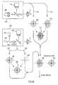
- Figure 1 is a flow diagram illustrating the acquisition of iris image data and the use of the data for a subsequent laser treatment;
- Figures 2A, 2B, and 2C are block flow diagrams illustrating the acquisition of iris data in conjunction with refractive characteristic data, the generation of a treatment based on that data, and the use of that treatment data in conjunction with an iris image to perform laser surgery;
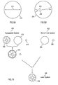
- Figure 3 is a diagram illustrating combined ablation profiles developed from wavefront data and from surface topography data;
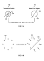
- Figure 4 is a cutaway representation of an eye, as well as associated diagnostic tools used to determine particular refractive characteristics of the eye;
- Figure 5 is a diagram illustrating various features of an eye that can be used as characteristic iris data in a system and method according to the invention;
- Figure 5A is an eye diagram similar to Figure 5, showing a marker according to an embodiment of the invention.
- Figure 6 is a flow diagram illustrating the use of stored iris data and imaged iris data to translate a desired treatment into an actual treatment according to the invention;
- Figure 7 is a flow diagram illustrating an alternative technique employing stored iris data to align a treatment;
- Figures 8A and 8B are display images illustrating the technique of Figure 7;
- Figures 9A and 9B are diagrams illustrating a laser alignment beam/imaging system alignment technique according to the invention;
- Figure 10 is a diagram illustrating alternative alignment techniques according to the invention;
- Figures 11A and 11B are further refinements of alignment techniques according to the invention;
- Figure 12 is a block diagram of a wavefront sensor for use in a system according to the invention; and
- Figure 13 is a diagram of an exemplary fixation image for use in the wavefront sensor of Figure 12.
- Figure 1 shows the general flow of a method of using a system implemented according to an embodiment of the invention. At
block 10, the iris is imaged in conjunction with acquiring refractive data using a diagnostic tool. This imaging and the use of the diagnostic tool can take many forms. For example, the tool can be used well in advance of the laser treatment, such as using a corneal surface topography system to determine a corneal or refractive profile. Or it can be used immediately before refractive surgery. In any case, the imaged iris or some representation of the iris is maintained with the data developed by the diagnostic tool. - Proceeding to block 12, a treatment is then developed based on the data provided by the diagnostic tool. For example, this treatment may treat for a certain degree of myopia and an irregular astigmatism. This treatment can be, for example, a treatment developed using the algorithms of
PCT/EP95/04028 , entitled "Excimer Laser System for Correction of Vision with Reduced Thermal Effects," published April 25, 1996, which provides a dithering algorithm to modify a corneal profile, in conjunction with the distributed system ofU.S. Patent No. 5,891,132 , entitled "Distributed Excimer Laser Surgery System," issued April 6, 1999. This treatment, however, is normalized to the stored representation of the iris image. By doing so, subsequent modifications to the treatment based on additional diagnostic tool data can be normalized to subsequent iris images. - Further, the treatment itself is preferably aligned to the iris of the patient. This is done at
block 14, where the laser aim and the treatment pattern are normalized to the image of an iris of the patient under treatment. This normalization can take very general forms, such as a translation of the aim of the laser to an appropriate point, or more sophisticated forms, such as by rotation or even scaling and skewing of the treatment to match the iris image that is presented to the laser system. - Proceeding to block 16, the laser treatment is then performed. Of note, during the laser treatment the system can periodically or even continuously match the iris data to the stored representation of the iris data, in essence tracking the patient's eye.
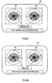
- Turning to Figures 2A, 2B, and 2C, the general flow of determining refractive data, normalizing to the iris image, generating a course of treatment, and then applying a course of treatment is shown in a system according to the invention. Refractive characteristics of an eye to be treated are determined by a corneal
surface topography system 100 and awavefront sensor 102. Both of these devices generally provide data indicative of refractive characteristics of the eye. In addition, a computer workstation orcomputational unit 104 is shown that is used to create a customized course of treatment based on the data provided by the diagnostic tool. Although shown as aseparate workstation 104, such as for use in a distributed system like that disclosed inPCT/EP97/02821 , theworkstation 104 and/or its functionality could be incorporated within many of the other components of the system of Figures 2A, 2B, and 2C. For example, also shown in Figure 2C is alaser system 106, which receives both the treatment generated by theworkstation 104 and corresponding iris data. Thelaser system 106 could incorporate the functionality of theworkstation 104, generating an appropriate laser treatment within thelaser system 106 itself. - Beginning in Figure 2A, the
corneal topography system 100 gathers corneal topographic data from a patient's eye E. The illustrated topography system includes Placido disk-type hardware 108 as well as a pupil oriris camera 110. These components are known to the art, and a variety of techniques are known to produce corneal topographic data. For example, the System 2000 by EyeSys produces corneal topographic data, and ORBSCAN II® topography system by Bausch & Lomb/Orbtek, Inc. of Salt Lake City, Utah, produces not only surface corneal topography, but also overall topography for the various components of the eye. The former system is a Placido disk based system; the latter is an automated slit lamp system. The ORBSCAN II® system uses surface elevations and ray tracing to determine refractive errors of the eye. Thetopographic system 100 typically can producedata output 112 in a variety of formats and gathered using a variety of techniques, such as absolute corneal height at a variety of points, corneal curvature at a variety of points, and the like. - Besides the
corneal data 112, thecorneal topography system 100 also acquires a corresponding "snapshot" of the visible surface of the eye E, providing first iris (and pupil)image data 114 representative of an iris (and pupil)image 120. Many corneal surface topography systems have a camera that can acquire this image. As is further discussed below, thecamera 110 can provide theiris image data 114 in a variety of formats, such as a standard image format, or as a reduced format in which various iris or pupil artifacts are identified. Such artifacts can include those identifiable along the edge of the interface of the pupil and iris. Theiris data 114 can be some combination of image and recognized artifacts of the iris, the pupil, their interface, or other eye structures as well. - The
camera 110 can be a variety of camera types, such as a visible light, infrared, or other camera suitable to capture theiris image 120. Preferably, the image is acquired at the same time that the topography components (Placido disk-type hardware) 108 are gathering thetopography data 112, although before or after would also be acceptable. - As illustrated in Figure 2A, the
topography data 112 and theiris image data 114 are preferably related according to some coordinate system, as represented by overlaidimages 116. The relationship between adetermined topography 118 and theiris image 120 is maintained in the data. - As discussed below, the
iris image data 114 for theiris image 120 is useful for aligning a surgical tool (here, the laser system 106). Thedata 114, however, is also useful for normalizing data from various other ophthalmic diagnostic instruments. Specifically, thewavefront sensor 102 also analyzes the refractive irregularities or aberrations in the eye E. In thewavefront sensor 102, preferably acamera 122 is focused onto the eye E in front of certain "trombone"optics 124. The trombone optics 124 (e.g., a focus or optical path adjusting tuning device or optics) is used to change the optical path length and focus alaser 126 onto the retina of the eye E. Thetrombone optics 124 can be used to determine and compensate for the low order aberrations of the eye E, such as defocus. In one embodiment, thewavefront sensor 102 gathers data for determining optical aberrations in the eye E via alenslet camera 128. As discussed above, a variety of other wavefront sensors or other type of systems for determining refractive ophthalmic wavefront aberrations can be employed. - As with the corneal
surface topography system 100, thewavefront sensor 102 preferably providesaberration data 130 and iris (and pupil)image data 132 from thepupil camera 122. These data establish an aberration profile 134-e.g., a wavefront sensor spot profile, from which centroids of the spots are determined in determining the wavefront aberrations of the eye, as in Williams-and an iris (and pupil)image 136. Theiris image data 132 can be similar to theiris image data 114. Thewavefront sensor data 130 and theiris image data 132 also are normalized to each other, as illustrated by an overlappingreference frame 138 in Figure 2A. The pupil can be dilated when theaberration data 130 and the image data are acquired, or can be left undilated. - Various types of refractive data can be determined and employed in developing a course of treatment for refractive surgery, such as LASIK. These data can include corneal topographic data, wavefront sensor data, corneal thickness data or other differential profiles (e.g., using ultrasound) of eye components, and other types of refractive data developed from various sources, such as from slit-scanning or optical coherence tomography techniques. For example, ultrasound can be used to measure not only corneal thickness, but also the epithelial and other eye surfaces, the amount of stromal component in a microkeratome-cut flap (for LASIK), the residual stroma under the flap, and the like. These data are typically provided on a point-by-point basis on the eye E, at varying resolutions. For example, the
corneal topography data 112 from thecorneal topography system 100 generally will have a higher resolution than thewavefront sensor data 130. Similarly, certain types of data are directed towards one aspect of the eye E, such as cornealsurface topography data 112 mapping the surface topography of the eye E, while other data may reflect other aspects of the eye E, such as total refractive error found in thewavefront sensor data 130 from thewavefront sensor 102. - Further, the refractive diagnostic tools could be of a variety of configurations, such as a fixed, bench-type system, hand-held, or multiple systems integrated into a single tool. One skilled in the art will recognize that the techniques according to the invention can be implemented in a wide variety of actual physical embodiments.
- In one embodiment of the invention, these data sets are normalized to each other for more accurate generation of a refractive treatment. Here, the
topography data 112 and its correspondingiris image data 114 are normalized to thewavefront sensor data 130 and itsiris image data 132. For example, these two data sets are normalized to each other (illustrated by a diagram 140) based on similarities of theiris image 120 and the iris image 136 (illustrated by an iris image 142). As discussed above, this normalization may result from an overlapping of the iris images themselves, or instead from an adjustment of characteristic elements of the iris (and pupil) images, as discussed below in conjunction with Figure 5. - In a particular embodiment shown in Figure 2B, the
aberration profile 134 is processed (e.g., via fitting Zernike polynomials, as discussed in Williams and herein) to develop wavefront aberration data shown as a pupil wavefront aberration (e.g., contour)plot 160. Thewavefront sensor data 130 and the iris image data 132 (Figure 2A) are normalized also to each other, as illustrated by an overlappingreference frame 162 in Figure 2B. As discussed above, the pupil is preferably dilated when theaberration data 130 and the image data are acquired, and these data sets are normalized to each other for more accurate generation of a refractive treatment. Thetopography data 112 and its correspondingiris image data 114 are normalized to thewavefront sensor data 130 and itsiris image data 132. For example, the normalization of these data is illustrated by a (superimposed) diagram 164 based on similarities of theiris image 120 and the iris image 136 (illustrated by an iris image 142) in parallel to the discussion of Figure 2A above. Thetopography data 118 extends over a larger portion of the eye, such as over most or all of the cornea, while the wavefront aberration plot (or data) 160 generally extends only over the pupil or a portion of the pupil. Some correlation between the pupil wavefrontaberration contour plot 160 and thetopography 118, when overlapped as in or similar to the diagram 164, may be apparent, as will be appreciated by those skilled in the art even if no iris image data are used for alignment or for normalization. For normalizing or superimposing the topography and the wavefront aberration data (e.g., thetopography data 118 and the pupil wavefront aberration plot 160), suitable account may be taken of the variations in optical path length (e.g., from the wavefront aberration data) or refractive index (e.g., by averaging refractive indices) of the eye in order to correlate these data, as will be appreciated by those skilled in the art. - Whether data are generated according to the procedure outlined in Figure 2A or in Figure 2B, as illustrated in Figure 2C, a computer program then generates a
treatment profile 144. This can be done, for example, in a stand-alone computer 104, a computer connected to the Internet or other network, or in a computational system that is part of thelaser system 106, thetopography system 100, thewavefront sensor 102, or other systems. The treatment generated could be a variety of treatments. For example, an irregular treatment pattern could be performed, as illustrated in the aforementionedU.S. Patent No. 5,891,132 , or a variety of other types of treatments could be performed, including, but not limited to, a variable spot size, a scanned slit, or a fixed scanned spot size laser treatment. Regardless of the treatment performed, it is generated with respect to thedata iris image 142. - The data from the various diagnostic tools can be used in a variety of ways to create treatments. For example, the
data 130 from thewavefront sensor 102 could be solely used to create a treatment, or, instead, thedata 112 from cornealsurface topography system 100 could be used. Other alternative types of refractive diagnostic tool data can similarly be used solely to create treatments. Advantageous aspects of the data from the various tools could be combined to yield better overall refractive treatments. For example, the cornealsurface topography system 100 returns surface topography data regardless of the amount of dilation of the pupil, but thewavefront sensor 102 may be limited by the amount of dilation present in the pupil (i.e., thewavefront sensor 102 typically only measures refractive effects of optical elements that are in the optical path). Therefore, as illustrated by the diagram 164 in Figure 2B, thedata 112 from the cornealsurface topography system 100 is employed over a surface area larger than the dilated pupil, while thedata 130 from thewavefront sensor 102 is used for the central portion within the area of the pupil. In both cases, thedata 130 and thedata 112 can be reconciled by a first spatial normalization using theirrespective iris images - Such a technique is illustrated in Figure 3, in which ablation profiles based on wavefront data and surface topography data are combined. Illustrated in Figure 3 first is a surface topography based
ablation profile 162 developed from surface topography data. This data is valid even outside of the pupil, illustrated as apupil diameter 160. To compare, a wavefront basedablation profile 164 developed from wavefront data is generally only valid within the area of thepupil diameter 160. So, the two are illustrated as a combinedablation profile 166 by using the wavefront basedablation profile 164 within thepupil diameter 160 and using the surface topography basedablation profile 162 outside of thepupil diameter 160. In this example, each ablation profile is first calculated from the corresponding data before the profiles are combined. Other techniques could alternatively combine the captured data before an ablation profile itself was calculated. Elevation-based topography systems such as the ORBSCAN II® topography system available from Bausch & Lomb/Orbtek, Inc. are especially advantageous when used with the wavefront sensor. However, other topography systems, such as curvature based systems, are also useful in the practice of this invention. Other types of systems that are useful include dual camera systems such as described inU.S. Patent Nos. 5,159,361 and4,995,716 . - The ORBSCAN II® topography system is a slit-scan elevation based, topography system that simultaneously measures both surfaces of the cornea as well as the front of the lens and iris. Each measured surface can be displayed as maps of elevation, inclination, curvature or power. A full-corneal map of pachymetry is also derived from the measured surfaces of the cornea. Raytraced optical computations can be used to ascertain the visual effect of the various optical components within the ocular anterior segment. ORBSCAN II® topography measurements are based on diffuse reflections rather than specular reflections, to precisely detect the surface height rather than surface curvature. Use of a specularly reflected image from a placido or other reflective target to measure surface slope can be used in combination with measurement of diffuse reflections as will be apparent to those skilled in the art. For illustrative descriptions of the elevation-based, ORBSCAN II® topography system, see
U.S. Patent Nos. 5,512,965 and5,512,966 by Richard K. Snook. Data from the ORBSCAN II® system can be accurately and seamlessly transitioned into the overall refractive data from the wavefront sensor. - It is also possible for data from the wavefront sensor to be used to "calibrate" data in the topography system. Because the wavefront sensor describes the overall refractive error in the eye, it can allow the software for the topography system to correlate a surface topography at any particular point with an overall refractive error (determined by a wavefront sensor) associated with those points. Thus calibrated, the topography system data can then be used to create an overall refractive error profile.
- As another example, the data from various diagnostic tools can be combined to provide an overall model of the optical elements in the eye. For instance, a corneal surface topography system could provide surface data, an ultrasonic system could provide corneal thickness data, and a wavefront sensor could provide overall refractive error data. By "subtracting out" the effects of the surface data and the thickness data, optical elements past the cornea thus can be modeled using the various sets of data.
- Turning to Turning to Figure 4, a cross-sectional view is shown of the eye E including a
cornea 450, alens 456, and aretina 458. Thecornea 450 includes a number of layers, such asepithelium 452 andstroma 454. These various components, particularly thecornea 450 and thelens 456, combine to form an overall refractive (optical) power and a refractive characteristic for the eye E. A number of factors can contribute to refractive (e.g., wavefront aberration) errors, including, but not limited to, irregularities in thecornea 450 or in thelens 456, and the distance (e.g., in the sense of a defocusing aberration) from thecornea 450 andlens 456 to theretina 458. - Also illustrated in Figure 4 are notations indicating various types of diagnostic tools particularly suited to analyze refractive and other characteristics of particular portions of the eye E. These tools can provide different types of data for different portions or components of the eye E. For example,
ultrasonic techniques 460 can typically determine the thicknesses of theepithelium 452 and thestroma 454, which provide the overall thickness of thecornea 450. There are a variety of ultrasonic techniques that can be used, including a pachymeter as well as a technique described in U. S. Patent No.5,293,871 , entitled "System for Ultrasonically Determining Corneal Layer Thickness and Shape," issued March 15, 1994. - Corneal surface topography systems 462 typically provide and analyze corneal surface topography. Topography systems, such as the ORBSHOT™ by Orbtek and the System 2000 by EyeSys, typically exhibit a very high resolution, but are restricted to the surface of the
epithelium 452 of thecornea 450. - A combined refractive
diagnostic tool 464, such as the ORBSCAN II® topography system by Orbtek, typically determines and analyzes a variety of thicknesses and surfaces within the eye. This can include the thickness of thecornea 450, the surface topography of thecornea 450, the surface of thelens 456, the distance from thelens 456 to thecornea 450, and the distance from these front optics of the eye to theretina 458. - Finally, in Figure 4, a wavefront sensor, illustrated by 466, such as the previously described
wavefront sensor 102 or the wavefront sensor in Williams, provides data on the overall refractive aberrations of the eye, shown as an aberrated wavefront profile (data) 468. The wavefront sensor techniques are empirical in nature-concerned with characterizing the wavefront of light external to the eye that was reflected from theretina 458 rather than with the physical characteristics of any particular optical component of the eye E. - Referring again to Figure 2C, based on the treatment generated 144, typically, a course of treatment, such as a series of shots, a series of scanned slits at various aperture sizes, or a variety of other types of treatment, is provided for a particular type of
laser system 106. The course of treatment, illustrated by aprofile 146, is itself spatially referenced todata 148 representing the iris image. Thedata 148 again could be an image of the iris itself, a high contrast representation in black and white of the iris, a location representation of various natural or artificially made features of the iris or cornea, or a variety of other representations of the iris. In general, thedata 148 representation of the iris should be suitable to allow the course oftreatment 146 to be aligned with the actual iris of the eye E when the eye E is to be treated by thelaser system 106. - The
laser system 106 is then loaded with the treatment profile, including the course oftreatment 146 and theiris data 148. Referring to Figure 2C, thelaser system 106 can be of a variety of types, such as a 193 nanometer excimer laser, and will typically include alaser 150, an aiming system 152 (e.g., a series of optical components used to direct light from thelaser 150 to the eye E), acamera 154, and acontrol system 156. A lower power aiming or reference beam (not shown) typically is used in conjunction with thelaser 150. The aiming beam, for instance, a laser beam, can be monitored by thecamera 154, which is typically an infrared camera, and can be used to aim thelaser 150 as described inU.S. Patent No. 5,620,436 , entitled "Method and Apparatus for Providing Precise Location of Points on the Eye," issued April 15, 1997 [PCT/EP95/01287, published October 19, 1995 ]. - In operation, the
camera 154 provides an image of the iris I (see Figure 2C) of the eye E to thecontrol system 156, which controls the aimingsystem 152. The image of the iris I actually provided to theexcimer laser system 106 is compared to theiris data 148 associated with the course oftreatment 146. The aim of thelaser head 150 is then adjusted such that theiris data 148 is co-aligned essentially with the image of iris I provided by thecamera 154. This can entail translation, rotation, scaling, skew, or a variety of other transformational functions. The translation that is applied to theiris image data 148 necessary to align it with the iris I is similarly performed on the course oftreatment 146, such that the ultimate course of treatment, when it is applied, corresponds to a course of treatment necessary to reduce the optical effects as predicted in thetreatment generation 144. - The data of the course of
treatment 146 itself can be altered, or the aim of thelaser system 106 or the rotational alignment of the patient instead can be altered. Regardless of the methodology, theiris data 148 are used to align the iris I before thetreatment 146 is applied. - Various types of eye surgery can benefit from the disclosed techniques. PRK can be applied to the external surface of the eye, or a LASIK procedure can be performed by first resecting a portion of the cornea and then applying laser treatment underneath. Further, the techniques can lend themselves to other, non-keratectomy-types of treatments, such as excimer keratotomy, or various types of thermal approaches to refractive correction. These courses of treatment can be accurately aligned with the iris of the eye, such that the calculated treatment pattern is provided more precisely to theoretically optimal positions.
- Other benefits flow from using the iris data associated with both the diagnostic and the treatment data. For example, when a patient is in an upright position for diagnostic evaluation, sometimes the position of the eye may rotate slightly within the eye socket compared to when the patient is in a reclining position. Similarly, the patient's head alignment can affect eye rotation even when the body stays in the same position. Although the patient's brain can compensate for a slight amount of such rotation, in a highly precise correction treatment pattern for higher order defects, the change in the rotational alignment literally can rotate the eye out of position with respect to the treatment, causing a faulty treatment to be applied to the eye. The effects of such a misalignment typically are not pronounced for fairly basic courses of treatment, such as myopia and hyperopia, and even for a minor treatment of astigmatism, but with higher order defects, such as irregular astigmatism, glare, halo, and the like, the benefits of the highly precise treatment can be lost unless precise alignment with the optimal spatial treatment position is obtained and maintained. The techniques according to the invention can reduce such loss of alignment.
- With respect to the iris matching and alignment itself, a variety of techniques can be employed, either using actual images of the iris or digital representations of various features of the iris. These techniques have been employed in recognition systems based on the unique features of an iris, such as
U.S. Patent No. 5,572,596 to Wildes, et al., issued November 5, 1996 , entitled "Automated, Non-Invasive Iris Recognition System and Method," assigned to David Sarnoff Research Center, Inc. of Princeton, New Jersey, andU.S. Patent No. 4,641,349 to Flom, et al., issued February 3, 1987 , entitled "Iris Recognition System," both of which are incorporated by reference herein in their entirety. The former of these patents discusses scaling, rotation, and translation; the latter of these patents discusses the various features that can be used to uniquely match and identify an iris, and also discusses that a control mechanism can be used to adjust the position of the iris relative to the camera. In an embodiment of the present invention, a similar technique additionally can be used to aim thelaser system 106. Similarly,U.S. Patent No. 5,291,560 to Daugman, issued March 1, 1994 and entitled "Biometric Personal Identification System Based on Iris Analysis," assigned to Iri Scan, Inc. of Mount Laurel, New Jersey, also incorporated by reference herein in its entirety, further discusses the "optical fingerprint" provided by the iris. The pattern matching and feature matching techniques of these patents and otherwise known to the art are employed for alignment purposes rather than strictly identification purposes. - Alternatively, or in addition, the
camera 154 of thelaser system 106 can receive an image of the iris I which is then displayed on a screen. Theiris image data 148 can then be superimposed to allow the physician, technician, or other healthcare worker to manually aim or adjust thelaser system 106, or to manually verify the aim of thesystem 106. - Referring to Figure 5, the iris I of the eye E is illustrated in more detail, showing how particular features can be employed for matching the patient's eye E for treatment with his or her previously stored iris I image. For example, a set of
points 200, defining generally circular features such as collarattes, can be employed as descriptors, as canconcentric furrows 202 orradial furrows 204. Other features that can be used are generally described in the above-referencedU.S. Patent No. 4,641,349 to Florm , which include pigment spots, crypts, atrophic areas, tumors, and congenital filaments. Similarly, the pupil can be used in iris matching as well, for example, as a center reference point from which iris features then define the rotational position of the eye. Fewer or greater features can be employed, for example, depending on the complexity of the treatment to be applied. If the treatment is rotationally symmetrical, such as a treatment for pure myopia or hyperopia, rotational displacement is of no consequence, so the center point can be located with respect to the pupil. But with greater complexity of treatment, more detailed features can be employed for more precise registration of the eye E before treatment. Alternatively, artificial features can be imposed upon the eye E, for location, including in the iris area. For instance, three laser marks can be created on the eye E if the treatment is to occur before the laser marks would heal. A marker in the form of thermal marks made, for example, with a Holmium laser would provide information about rotation and translation of the eye prior to and during surgery. Various marker shapes are also envisioned. As shown, for example, in Figure 5A, radially extendingmarkers 201 could provide eye movement and alignment data. As shown,reference 203 denotes, e.g., a scleral boundary or alternatively, a gray-scale profile determined from an iris recognition program such as that provided by Sensomotoric Instruments, Teltow (Germany). Themarkers 201 have a proximal segment 201' beginning around the approximate center of the eye E and adistal segment 201" that deviates from being collinear with segment 201'. It can be seen thatradial marker 201 traverses theboundary 203. It will be appreciated also that a marker should have sufficient range to be seen during the refractive procedure; i.e., after the flap is lifted in a LASIK procedure, for example. Alternatively, the marker could consist of a suitable dye, particularly one visible or detectable in infra-red light to be viewed by an infra-red camera. The dye could further be used as a tattoo by e.g., coagulating the dye after application or coagulating the dye and applying it to shrinked collagen. Still further, a combination of dye and special glues could be used. Such a dye or dye-based market should be visible/detectable for the duration of the refractive procedure. In cases where the pupil is dilated, the marker should remain visible/detectable for at least 15 minutes, preferably up to an hour, after its application. This is due to the finding that dilation induces ocular aberration and sufficient time should pass for the dilation-induced aberration to subside. Then, the diagnostic steps can be taken and the treatment followed soon thereafter. Further, other identifying portions of the visible surface of the eye can be used, apart from the iris I. In all of these techniques, features of the visible portion of the eye E are employed for registration between the diagnostic system, the developed treatment, and the actual treatment as applied to the eye E. - Turning to Figure 6, various adjustments that can be made to the desired treatment based upon the image of the actual iris I as received by the
laser system 106 are illustrated. Referring again to Figure 2C, the treatment generated 144 is provided as a desiredtreatment pattern 146 for controlling thelaser system 106. The associated referenceiris image data 148 from the diagnostic tools is used to align thetreatment pattern 146 with the patient's eye E. Theiris image 206 is provided by thepupil camera 154 of thelaser system 106 and provided to thecontrol system 156. Thecontrol system 156 compares theimage 148, or the descriptors derived from that image, to theiris image 206. Based on the comparison, a variety of scaling functions is applied to the desiredtreatment 146. For example, it may be determined, based on the overall size of theactual iris image 206, that the treatment should be reduced in scale because of different focal distances of thediagnostic tools laser system 106. So a scaling 208 is calculated and applied, yielding a scaledtreatment 210. Then, it may be determined that the now scaled, desiredtreatment 210 must both be translated and rotated, as indicated by a translation androtation function 212. This in turn is applied to the scaled desiredtreatment 210, yielding theactual treatment 214. These data are then used by thelaser system 106 to perform an actual treatment. - Alternatively, if the
control system 156 has great enough computational power, it is possible for each shot (i.e., laser pulse) to be appropriately rotated and translated. This may be desirable if the eye E displays a large degree of dynamic rotation and movement during the treatment, for example. Then, theiris image 206 can be tracked and the scaling functions 208 and 212 illustrated in Figure 6 applied dynamically to each specific shot or sequence of shots in the desiredtreatment pattern 146. In this manner, the movement of the eye E can be accommodated shot-by-shot. This technique can be combined with the aiming laser technique ofPCT/EP95/01287 such that the exact placement of each shot or series of shots relative to theiris image 206 is determined before the shot or shots are applied. - Therefore, in embodiments of the invention, any of a variety of diagnostic instruments can be fitted with a camera or other imager that acquires an image of the pupil, the iris, or other distinctive characteristics of the exterior of the eye and exports data corresponding to that image. Then, when a refractive treatment, such as an excimer laser treatment used in LASIK, is performed, the stored image (or its distinctive components) is compared to the actual image of the pupil, iris, or eye to align the laser such that the treatment will fall precisely as calculated.
- In an exemplary embodiment of the invention, a method of eye alignment and characterization is described as follows.
- A marker is provided in a selected region of the patient's eye. Various marker types and shapes are described elsewhere in the description and include, but are not limited to, thermally induced marks, radial markings, and dye markers. A first image of the patient's eye is acquired with the pupil undilated, thus the image includes an image of the iris and the marker. Preferably, the image is an infra-red image acquired with an infra-red camera, however, a visible light image is also suitable. Thus, the marker will be suitably visible and/or detectable in infra-red light. The pupil is then dilated by light intensity variation or chemically, and a second image of the eye, including the dilated pupil and marker is acquired. A diagnostic measurement of the eye in the dilated state is obtained, the diagnostic measurement preferably being a wavefront aberration measurement or, alternatively, a topographic or other refractive diagnostic measurement. A computer system is then used to develop a photo-refractive treatment from the diagnostic measurement for refractive correction of the patient's eye. If a dye is used as the marker, it is preferable that the dye remain visible and/or detectable for at least 15 minutes, preferably up to an hour, after application of the dye or for a sufficient time for dilation-induced aberrations to subside.
- According to the invention, the method finds further utility by aligning the second image with the first acquired image, preferably by comparing the markers in the respective images or, alternatively, by comparing other corresponding characteristic features in the respective images. Similar to other aspects of the invention described herein, development of the photo-refractive treatment is accomplished by aligning the diagnostic measurement with the marker on the patient's eye. In an aspect of the invention, the alignment procedure may incorporate iris pattern recognition provided through the computer system. Various iris pattern recognition software is known in the art and is commercially available.
- The practitioner has the option of implementing the developed photo-refractive treatment in a real time sequence immediately following acquisition of the second image. In this case, the eye image includes the dilated pupil, thus no iris pattern from the second image can be compared to and aligned with the iris image of the first acquired image. Consequently, the markers are used in the respective images to correlate, normalize, or otherwise align the images and the refractive or diagnostic tools associated with those images. Alternatively, photo-refractive treatment of the eye may be delayed for hours, days, etc. and performed electively. In this case, another image of the patient's eye, including an image of the iris will be acquired preferably by a refractive tool such as, for example, a photo-ablative laser system including a pupil or iris camera, preferably an infra-red camera, for acquiring the image. Prior to treatment, that image will be aligned with the first acquired iris image and in conjunction with the developed treatment, based upon the diagnostic measurement. Of course, through image storage, digitization, etc., alignment of the developed diagnostic treatments, the diagnostic tools, the refractive tool or any combination thereof can be verified and such alignments can conveniently be displayed to the practitioner though a display system.
- A system for performing the alignment and photo-refractive treatments discussed above includes most basically a first camera used to acquire the first image which includes an iris image of the eye, a refractive diagnostic instrument for making a wavefront, topography, pachymetry or other refractive diagnostic measurement as one skilled in the art will appreciate, a laser system capable of providing the developed photo-refractive treatment that preferably includes a second camera used to acquire another image of the eye, a computer system used for developing and aligning the photo-refractive treatment linked to the laser system, the first camera and the diagnostic tool, and a control system attending to implementation of the photo-refractive treatment that is suitably linked to other components of the system. In an aspect of the invention, a second refractive diagnostic instrument that further includes a camera which is used to acquire a further image of the eye that includes an iris image can also constitute a component of the overall system. A display system can also advantageously be linked to the overall system.
- Turning to Figures 7 and 8A-8B, shown is an alternative technique to employ a previously captured image of an iris I to insure appropriate alignment of a laser treatment with the calculated treatment profile. Generally, Figure 8A illustrates a
display 252 provided by thecamera 154 of thelaser system 106 in Figure 2C. On the left is captured iris I imagedata 250 captured when a refractive diagnostic tool was used to determine the refractive characteristics of the eye E. From this data, and coaligned with this iris I imagedata 250, a treatment profile had been developed. On the right side of thedisplay 252 is real timeiris I image 254, which is returned by thecamera 154 of thelaser system 106. As can be seen, thereal time image 254 is slightly rotationally misaligned compared to the capturedimage data 250. This provides the physician with an opportunity to realign the patient's eye E, yielding in Figure 8B a properly aligned real timeiris I image 256. Preferably, the display includes reference axes that allow the physician to easily determine rotational misalignment. The system could also provide, for example, a cursor that the physician could place over identifying features to determine precisely the rotational location relative to the axis. - Figure 7 illustrates the steps of using the system of Figures 8A and 8B in aligning the iris. First, the captured iris I image
data 250 is displayed in astep 260. Simultaneously, thereal time image 254 of the iris I is displayed at astep 262. When theexcimer laser system 106 is a Keracor 217 employing an eye tracker, the physician then activates the eye tracker at astep 264, which centers thereal time image 254. The eye tracking system on the Keracor 217 provides for centering the iris I, but does not provide for rotational alignment of the iris. - Proceeding to a
step 266, an axis is displayed on both the captureddata 250 and thereal time image 254. The physician then compares the images on the screen, and determines an amount of rotation necessary to align the two images of the iris I. The physician then rotates the eye E so that the real time iris I image 256 rotationally corresponds to the capturediris image data 250. The physician can do this manually, such as using a suction ring or by repositioning the patient's head. Further, the system can provide for a "virtual" rotation of the patient's eye E by rotationally translating the treatment profile by an amount specified by the physician. In any case, the eye tracking system first provides for centering of the real timeiris I image 254, and the physician then effects the rotational alignment of the iris I image 256 compared to the capturedimage data 250. - Referring to Figures 9A and 9B, a technique for developing the axis as illustrated in Figures 8A and 8B is shown. Specifically, as in Figure 8A, an
iris image 270 is shown corresponding to an axis in the laser system. In this case, anaxis 272 is created by rapidly scanning the aiming system with its visible aiming beam left to right over the X axis. Thus, when the doctor views the image of Figure 8A, the axis on the real time iris I image 254 is created by the aiming system of the laser itself, which is the same aiming system used to aim the beam. Therefore, the true X axis of the laser will be known because the aiming beam scanned by that aiming system is creating that X axis. - Turning to Figure 9B, a further technique is illustrated for aligning the aiming system of the laser with the display or optical system. Assume in Figure 9B that again the
pupil 274 is shown in the optical system of the laser or on the eye tracker camera of the laser, but that the aiming beam is scanning over aline 276, which is not exactly aligned with the X axis of the optical system or the eye tracker. A technician can align the scanned aimingbeam 276 with the X axis of the optical system and the eye tracking system, rotating the scanned aimingbeam 276 to thetrue X axis 278 of the optical system and the eye tracking camera. Then, a line can be superimposed on the eye tracking system, or a line can be formed in the optical system that corresponds to the true X axis of the laser's aiming system. Further, this alignment can be periodically verified by scanning the aiming beam on the X axis and ensuring that that scanned aiming beam matches with the alignment axis within the optical system or on the eye tracking system video display. Translational X-Y alignment can be similarly adjusted and verified. - Turning to Figure 10, another technique is illustrated in which not only iris Iimage data is captured, but also other types of data in order to align the captured refractive data or treatment profiles among various systems. Specifically in Figure 10, illustrated is alignment data captured by a
topography system 500, awavefront system 502, and alaser system 504. If thewavefront system 502 has difficulty capturing iris I image data, or it is desired to fully dilate the eye before capturing the wavefront data, the disclosed techniques can allow alignment without such data. In that case, in one embodiment, the physician first makes areference mark 506 on the eye. Thatreference mark 506 then acts as a rotational alignment marker relative to an outline of theiris 508. The wavefront system encaptures the wavefront aberration data along with thepupil outline data 508 and thereference mark 506. - Then, the
topography system 500 is employed. Thetopography system 500, however, does capture the iris image data as illustrated by theiris image data 510. It also captures the outline of theiris 512 as well as the previously madereference mark 514,corresponding reference mark 506. These two are simultaneously captured as illustrated by theimage 516, and thus thetopography system 500 maintains a translational and rotational reference between theiris image 510, theiris outline 512, associatedreference mark 514, and the capture topography data itself. Further, thetopography system 500 can combine its data with awavefront system 502 based not on theiris image 510, but instead on the outline of theiris 512 and therotational reference mark 514. That is, thetopography system 500 andwavefront system 502, when their data is combined to develop a course of refractive correction, align their data based on the captured iris outlines 512 and 508 as well as the rotational reference marks 514 and 506. - Preferably the
iris image 510 is also stored so that when the course of treatment is calculated, it can be referenced to thatiris image 510. Then, thatiris image 510 is used by thelaser system 504 to align to a realtime iris image 518 captured by thelaser system 504. - Thus, the
laser system 504 employs theiris image 518 itself, thewavefront system 502 employs the outline of theiris image 508 with areference mark 506, and because thetopography system 500 employs both, both the initial diagnostic data between thetopography system 500 and thewavefront system 502 can be co-aligned, as well as the treatment profile based on that data when the ablation is performed by thelaser system 504. - This may be particularly useful when the
topography system 500 andwavefront system 502 are initially employed to capture diagnostic data and only later is thelaser system 504 employed. A temporary reference mark that is captured as the reference marks 514 and 506 can be applied to the eye, such as with the medical pen. Although that mark may be gone when thelaser system 504 is later used, because theiris image 510 was captured along with thatreference mark 514 by thetopography system 500, thelaser system 504 can employ its own capturediris image 518 to align the treatment. - Further, it is possible that the reference mark itself would not be needed. If the
wavefront system 502 andtopography system 500 are either simultaneously employed or employed without movement of the patient's eye or head, then it may be assumed that - the proper rotational alignment is maintained. Then, thewavefront system 502 need only capture the outline of theiris 508 and associate that with the outline of theiris 512 captured by thetopography system 500. This can be achieved by fixing the patient's eye, or by fixing the patient's head and moving the two diagnostic systems into position without the patient's head moving. If this technique is used, it may be further desirable to employ a rotational reference image, such as illustrated by the sailboat below described in Figure 13, to further ensure rotational alignment between the eyes when thewavefront system 502 and thetopography system 500 is used. - A variety of permutations of this arrangement are possible. Referring to Figure 11A, a
topography system 520 capturesiris data 522, but also as part of its analysis captures an axis ofastigmatism 524. Then, awavefront system 526 also captures wavefront data but not an iris image, but does detect the outline of the iris as illustrated by thecircle 528. The wavefront system also captures an axis ofastigmatism 530. Then, those axes of astigmatism are used to co-align the data captured by thetopography system 520 and thewavefront system 526. As a alternative of this technique, illustrated in Figure 11B, a ring ofillumination diodes 532 is installed on thewavefront system 502. The reflections of these diodes, illustrated by animage 534 is captured by a pupil camera of thewavefront system 502. Based on the distortion of positions of those illuminations of theillumination diode ring 532, as captured by theimage 534, again an axis ofastigmatism 536 is captured to be associated with the axis ofastigmatism 524 captured by thetopography system 520. This provides an additional basis with which to co-align the data from thetopography system 520 and thewavefront system 526. Further, in this case, the axis of astigmatism can both be based on the astigmatism created by the surface of the eye, rather than the overall refractive error of the eye as captured by thewavefront system 526 wavefront ablation profile. - Other alternatives include a system in which the two images are superimposed. Further, a variety of user interface tools can assist the physician, including the aforementioned cursor positioning and the software rotation of the treatment profile.
- Further, the use of iris data or other alignment data need not be continuous. The iris data can be used as an initial alignment tool, and then other simpler alignment techniques can be used throughout a course of diagnostic analysis or refractive treatment, such as the location of the iris alone. That is, the iris data can be used to establish the rotational alignment, and then the outline of the iris can be used to maintain translational alignment during a treatment Further, the rotational alignment can be periodically "spot checked" throughout a refractive analysis or treatment, dependent upon processing power, even while translational alignment is maintained based on the outline of the iris itself.
- As an additional side benefit, when the patient lies down and the iris I image (Figures 2C and 5) is acquired, the iris matching algorithm can determine not only the translation, scaling, rotation, and skew to match the
actual iris image 206, but can also validate the eye E that is being operated on. The iris-matching algorithm thus acts as a failsafe mechanism to ensure that a particular laser treatment is in fact the appropriate treatment for this patient rather than another patient. Similarly, it acts as a failsafe mechanism to ensure that the proper eye E is being operated on, as even the two irises of a single patient have different descriptive features. These failsafe mechanisms are especially useful in distributed systems, where the diagnostic information is acquired at a first location, the treatment is developed at a second location, which is subsequently applied at a third location. The system can provide a warning if it cannot match the features of the iris. - Like aiming of the
laser system 106, validation can be done automatically or manually, using a display with theiris image data 148 superimposed over the iris image from thecamera 154. - Turning to Figure 12, a block diagram of a
preferred wavefront sensor 300 is illustrated. Thewavefront sensor 300 is similar in concept to the wavefront sensor of Williams, but includes certain features that make it especially useful for receiving iris data and for sharpening the focus of light spots on a sensor used in determining the wavefront aberrations of the eye. In general, thewavefront sensor 300 focuses or scans a light (typically a laser) on the retina of an eye and then analyzes the light returned (i.e., backscattered from the retina) through the lens and corneal optics of the eye and imaged by a lenslet array. Based on optical aberrations in the eye's optics, the system develops an overall wavefront aberration analysis from the returned light. Generally, to perform the analysis, the returned light becomes aerial images formed by a lenslet camera on a sensor of the lenslet camera. From these images, the wavefront sensor develops a wavefront aberration map of what corrections are necessary to the eye's optics that would yield emmetropic, or very nearly emmetropic, vision. - To properly orient the patient's eye E, two 660-
nanometer laser diodes 302, shown in Figure 12, can be aligned at angles to the eye E. When spots on the patient's eye E from thelaser diodes 302 are merged into a single spot, by appropriate adjustment of the wavefront sensor 300 (or 102), the output beams of the laser diodes 302 (or optics directing these beams), the patient, or otherwise, the eye E is positioned at, or approximately at, a precise focal distance from the wavefront sensor 300 (or 102). Alternatively, the patient's eye E can be properly oriented by a physician, technician, or other healthcare worker by visually looking at an iris image of the eye E to find the correct focal distance from thewavefront sensor 300 to reduce the overall exposure on the eye E. In this case, there is no need for thelaser diodes 302. A light source,eye illumination 304, provides light for apupil camera 328 discussed below. - Once the eye E is properly aligned, it receives light from a light source 306 (e.g., a laser diode, such as a 780-nanometer output laser diode) along an optical path to the eye E. Preferably, the
laser diode 306 has more than one output power setting (i.e., two-power or multi-power modes), at least one at lower power for alignment and initial focusing and at least one at higher power for creation of a multi-spot image in a sensor (e.g., a lenslet camera) 312 discussed below. For example, typical lower and higher powers are 0.5 µW and 30 µW, respectively. These powers depend upon a number of factors, such as how long thelaser diode 306 is to remain turned on at higher power. - A portion of the beam from the
laser diode 306 first reflects from a beamsplitter 308 (e.g., 80% transmittance, 20% reflectance). The reflected beam passes through apolarizing beamsplitter 310, which ultimately improves the signal to noise ratio (or signal intensity) of light backscattered from the retina of the eye that is eventually detected by thelenslet camera 312, as discussed below. Thebeamsplitter 310 polarizes the light received from thelaser diode 306, generally passing light linearly polarized along one direction and reflecting light not polarized in that direction. The polarized light is then passed through a trombone-type prism 314 which is used to adjust the focus of the light from thelaser diode 306 onto the retina of the eye E, at which point light backscattered onto the lenslet array from the light impinging on the retina will also be correctly or nearly correctly focused. The light from thetrombone prism 314 is reflected from amirror 316, passed through a beamsplitter 318 (e.g., 20% reflectance, 80% transmittance), and then through a λ/4waveplate 320. The λ/4waveplate 320 is oriented to produce substantially circularly polarized light from the linearly polarized light. The significance of this will be appreciated in the discussion below of backscattered light returned (the "returned light") from the eye E to thepolarizing beamsplitter 310. - After passing through the λ/4
waveplate 320, the light is then focused onto the retina of the eye E. The light is backscattered or reflected from the retina and the backscattered light spot on the retina then passes back through the optical components of the eye E, such as the lens and the cornea. On the return path, the circularly polarized image light is retarded again by thewaveplate 320 to yield light linearly polarized perpendicular to the incoming linearly polarized light formed on first passage through thewaveplate 320, as discussed above. A portion of the perpendicularly polarized light then passes through thebeamsplitter 318, reflects from themirror 316, passes back through theprism 314, and returns to thepolarizing beamsplitter 310. At this point, all or most of the light is perpendicularly polarized, and is thus substantially reflected by thepolarizing beamsplitter 310 and then reflected by amirror 322 into the lenslet-imaging camera 312. To get some of the returned light into anadjustment camera 323, discussed further below, thewaveplate 320 can be tilted and/or rotated from its optimal orientation (e.g., rotated by approximately 5 degrees). In this implementation, the light received by theadjustment camera 323 would have a polarization substantially perpendicular to the returned light. Other schemes besides tilting or rotating the waveplate 320 from its optimal orientation for providing returned light to theadjustment camera 323, including changes to the optical path and optical components of the wavefront sensor 300 (or 102), are envisioned and are included within the scope of the present invention. For example, themirror 322 instead could be a device having a controllable transmittance and reflectance, such as a liquid crystal device, and the adjustment camera and any focusing optics can be positioned to receive a fraction of the returned light that is transmitted by the controllable device. In such an implementation, thebeamsplitter 308 would be unnecessary and the light received by the controllable device would have substantially the same or parallel polarization as the polarization of the returned light. - The
lenslet camera 312 is preferably a charged couple device (CCD) camera, such as a TM-9701 manufactured by Pulnix, which includes an array oflenslets 324, although other types of cameras and other sampling optics analogous to the lenslet array 324 (including optics separate from a camera) could be used. For example, an ICX 039DLA camera by Sony Corporation can be used for both thelenslet camera 312 and thepupil camera 328. Thelenslet array 324 forms aerial images on the light sensing element (e.g., CCD array) of thelenslet camera 312 from the returned light reflected by themirror 322. Thewaveplate 320 can help to reduce the amount of unwanted backscattered or stray light to improve the signal intensity or the contrast of the aerial images. Thelenslet array 324 focuses portions of the light that has initially passed through the optical components of the eye E so that the refractive wavefront aberration effects of the eye E can be determined, similar to what is disclosed in Williams. In this regard, once the wavefront aberrations, and thus phase error, of the eye E have been determined, they can be transformed to a required ablation profile for removal of corneal tissue to correct or improve vision by taking appropriate account of parameters of the eye E (e.g., the refractive indices of eye E components, and/or other parameters). One technique for determining an appropriate profile is to simply scale the wavefront data such that the scaled data generally corresponds to the amount of tissue needed to be removed from the patient's cornea. Laser systems can then remove that profile of tissue from the cornea. Marks on the eye E can be employed to aid in aligning the eye E during acquisition of wavefront sensor data. - Preferably, the
lenslet array 324 is an array of approximately 25 x 25 lenslets, each 600 square microns, such as a 0600-40-S manufactured by Adaptive Optics Associates, Incorporated. This lenslet size is smaller than the lenslet size described in the aforementioned 5,777,719 patent and in other systems, and is made possible because of the enhanced intensity of light to thelenslet camera 312 provided by components of thewavefront sensor 300 to be discussed below. The optical path of thewavefront sensor 300 shown in Figure 12 can also include lenses 326 (e.g., four lenses) and diaphragms or apertures 327 (to allow changes in beam sizes) that are typical of illumination, imaging, and focusing optics, and which also can represent other possible optical components omitted for clarity. For example, in one embodiment of the invention, the focal length of one or both of thelenses 326 about thetrombone focusing prism 314 can be changed, perhaps shortened, to accommodate a smaller beam width entering thelenslet array 324. In another embodiment, the range of possible dioptric measurements that can be made with the wavefront sensor 300 (or 102) can be changed, for example, with appropriate selection of thelens 326 in front of thelaser 306, to adjust for the natural distribution of poor eyesight in the general or a select population of patients. One way to do this is to position the lens 326 (e.g., a -5 diopter lens) in front of thelaser diode 306 such that the laser beam is no longer parallel. This provides a certain offset in diopters that can be used to test the patient's eye with the wavefront sensor 300 (or 102). In a nonlimiting example, the dioptric range can be modified from a symmetrical -8 to +8 diopters with a symmetrical design to an asymmetrical -13 to +3 diopters with an asymmetrical design, as will be appreciated by those skilled in the art. This can be done without changing the size of the trombone focusing prism 314 (or other tuning device) and/or parameters of the optics. - Alternatively to the position of the
lens 326, alens 338 could be moved into the path to thelenslet camera 312. A number of locations within the path to thelenslet camera 312 can be employed to adjust the overall range of the capturedwavefront sensor 300. It will be appreciated that by employing either thelens laser diode 306 typically will have some inherent "astigmatism" of its own. This can be aligned with astigmatism typically found in a patient's eye E, again increasing the overall range of thewavefront sensor 300. Specifically, such astigmatism is aligned "with the rule" as typical patient's astigmatism is found, and thelenslet camera 312 andcorresponding wavefront sensor 300 software can take into account this inherent astigmatism as providing an even greater range of determinable astigmatism. - A
pupil camera 328 is shown receiving (e.g., 20% of) the reflected light from thebeamsplitter 318. Thepupil camera 328 preferably provides theiris image data 132 for theiris image 136 via a control system (not shown) similar to or the same as thecontrol system 156 discussed below in the discussion of alignment techniques. To compare, data from thelenslet camera 312 is processed and ultimately provided as the aberration data. - The
pupil camera 328 is placed in the optical path between the eye E and thetrombone focusing prism 314, which allows thepupil camera 328 to focus on the pupil and iris of the eye E, irrespective of changes in the focal length of the remainder of the system for focusing on the retina. Thus, thepupil camera 328 can develop a clear image of the surface of the eye E independent of the depth of the eye E and the corresponding distance from the retina to the iris. - The wavefront sensor 300 (and 102) also employs an image used as a
fixation target 334, as shown in Figure 10. Thefixation target 334 is illuminated by alight source 336, and allows the patient to fixate and focus while theadjustment camera 323 is focused by theprism 314 on the retina. Thefixation target 334 is useful when the aerial images from thelenslet array 324 are brought into focus onto the sensor of thelenslet camera 312 by adjustment of thetrombone optics 314. The system advantageously provides an image for thefixation target 334, a nonlimiting example of which is the sailboat on water illustrated in Figure 10, and not simply a fixation point. Thefixation target 334 gives the eye E and the patient's brain a picture-like or actual picture image or scene-really some object or scene being viewed by the eye E-on which to focus. Focusing the eye E with a picture-like image typically is easier to accomplish than focusing to a point. The image of the fixation target allows the eye E to focus at infinity, as if the image were far away, which can aid in eliminating or reducing the effects of eye E accommodation or rotation as the aerial images are focused or the wavefront sensor data are acquired. In other words, the image of the fixation target prevents, or helps prevent to a certain extent, the eye E from focusing at less than infinity. - The fixation target image forces the eye E to rotate to its "normal" rotational position, thus minimizing rotational errors from the diagnostic analysis. Thus, with the
fixation target 334, a rotational frame of reference can be defined relative to the eye E. An asymmetrical image, such as the sailboat in Figure 10, that can be viewed at infinite eye E focus is preferable for helping the eye E maintain the normal or a pre-determined rotational position with respect to thefixation target 334, even with slight head movement. Thefixation target 334 can also be used to adjust the rotational position of the eye E in conjunction with recognition, location, and alignment of an iris of the eye E, such as that described above. A similar image can be used in other components according to the present invention, both diagnostic and treatment, to eliminate or reduce accommodation or rotational issues. - It will be appreciated by those skilled in the art having the benefit of this disclosure that various types of components can be used to substitute for components implemented in the wavefront sensor 300 (or 102), and various optical configurations are possible to form other embodiments of the invention. For example, a high intensity, collimated light source, or multiple light sources, for example, one low power and one high power, can replace the
laser diode 306. Theadjustment camera 323 can instead be placed in the path of themirror 322, and thelenslet array 324 of thelenslet camera 312 can have more or fewer lenslets, as desired or according to design. Further, it will be appreciated by those skilled in the art that all of these components are generally controlled by a control system, such as a microcomputer. A wide variety of other configurations are possible that are within the scope and spirit of the present invention. - The foregoing disclosure and description of the invention are illustrative and explanatory thereof, and various changes in the details of the illustrated apparatus and construction and method of operation may be made without departing from the spirit of the invention.
Claims (21)
- Eye tracking system being provided with an iris image (206) such that an actual aim of an excimer laser can be adjusted on a dynamic basis relative to the position of the iris.
- Eye tracking system according to claim 1, adapted to periodically or continuously match iris data (206) to a stored representation of the iris (148) data during laser treatment (146).
- Eye tracking system according to claim 1 or 2, adapted to track the iris image (206) and to dynamically apply scaling functions to each specific shot or sequence of shots in the desired treatment pattern wherein movement of the eye can be accommodated shot-by-shot.
- Eye tracking system according to any of the preceding claims, adapted to determine the degree of dynamic rotation and movement of the eye during the treatment.
- Eye tracking system according to any of the preceding claims, further comprising a laser system (106) comprising a pupil camera (154) for providing the iris image (206);
a control system (156) being provided with said iris image (206);
said control system (156) comparing a reference image (148) or descriptors derived from that image (148) to said iris image (206),
wherein based on the comparison a variety of scaling functions is applied to a desired treatment (146). - Eye tracking system according to claim 5, wherein the scaled treatment (210) is translated and/or rotated by a translation and rotation function (212), such that data for an actual treatment (214) are obtained which are then used by the laser system (106).
- Eye tracking system according to claim 5 or 6, wherein said control system (156) is adapted to receive data derived from the refractive characteristic data and the iris data (148) and to align the iris data to the iris image (206) before the control system (156) initiates the course of treatment.
- Eye tracking system according to any of the preceding claims, further comprising iris pattern recognition from said iris image (206), wherein said iris pattern recognition includes a gray scale analysis of the iris for generating a gray scale profile of the iris.
- Eye tracking system according to any of the preceding claims, adapted to display an axis on both the captured data and the real time image (206).
- Eye tracking system according any of the preceding claims, adapted to superimpose a line on the eye tracking system or form a line in the optical system that corresponds to the true X axis of the laser's aiming system (152).
- Eye tracking system according any of the preceding claims, adapted to periodically verify the alignment by scanning the aiming beam on the X axis and ensuring that that scanned aiming beam matches with the alignment axis within the optical system or on an eye tracking system video display (252).
- A method for alignment for refractive treatment of a patient's eye, comprising:making a diagnostic measurement of the patient's eye;acquiring a first image including an iris image of the patient's eye;determining a spatial relationship between the first image and the diagnostic measurement;developing the refractive treatment for the patient's eye based upon the diagnostic measurement;acquiring a second image of the patient's eye; andaligning the second image, including the determined spatial relationship with the first image in preparation for performing the refractive treatment.
- A system for aligning a refractive correction instrument with a patient's eye comprising:a refractive diagnostic tool adapted to provide refractive data about the patient's eye, wherein the refractive diagnostic tool comprises:a first camera adapted to acquire a first pupil and/or iris image of the patient's eye, wherein the refractive diagnostic tool is adapted to provide refractive characteristic data and corresponding spatially related iris data representing the first iris image; anda laser system adapted to apply a course of refractive treatment to the patient's eye, wherein the laser system comprises:a second camera adapted to acquire a second iris image,a laser adapted to apply the course of refractive treatment, anda control system adapted to receive data derived from the refractive characteristic data and the iris data and to align the iris data to the second iris image before the control system initiates the course of treatment.
- A laser system for applying a course of refractive treatment to a patient's eye, the laser system receiving the course of refractive treatment in association with spatially related iris data representing an iris image of a patient's eye, the laser system comprising:a camera adapted to acquire the iris image;a laser adapted to apply the course of refractive treatment; anda control system adapted to receive the course of refractive treatment and the iris data and to align the iris data to the iris image before the control system initiates the course of refractive treatment.
- A method of providing a course of refractive treatment to a patient's eye, the method comprising:determining refractive characteristics of a patient's eye;acquiring an image of a surface of the patient's eye while determining the refractive characteristics;developing a course of refractive treatment using the determined refractive characteristics; andaligning a refractive correction instrument with the patient's eye by aligning the acquired image of the surface with another image of the patient's eye received by the refractive correction instrument.
- A system for aligning a refractive correction instrument with a patient's eye, comprising:means for determining refractive characteristics of the patient's eye;means for acquiring an image of a surface of the patient's eye while determining the refractive characteristics;means for developing a course of refractive treatment using the determined refractive characteristics; andmeans for aligning a refractive correction instrument with the patient's eye by aligning the acquired image of the surface of the patient's eye with another image of the patient's eye received by the refractive correction instrument.
- A method of aligning a refractive correction instrument with a patient's eye, the method comprising:determining refractive characteristics of the patient's eye;from an iris of the patient's eye, acquiring a first image used for defining a spatial relationship between the iris and the determined refractive characteristics;storing a representation of the first image;from the iris of the patient's eye, acquiring a second image in preparation for performing a course of refractive treatment; andaligning the second iris image and the stored representation for normalizing the course of refractive treatment to the second iris image.
- A method of aligning refractive tools, the method comprising:capturing first iris image data from a patient's eye with the first refractive tool;capturing second iris image data from the patient's eye with a second refractive tool; andaligning the second iris image data with the first iris image data.
- A system for aligning refractive diagnostic and treatment data, comprising:a first ophthalmic diagnostic or refractive tool, employing first refractive data, the first ophthalmic diagnostic or refractive tool adapted to capture first ophthalmic alignment data and maintain that data as a reference for the first refractive data;a second ophthalmic diagnostic or refractive tool employing second refractive data, the second ophthalmic diagnostic or refractive tool adapted to capture second ophthalmic alignment data as a reference for the second refractive data; andmeans for associating the first refractive data with the second refractive data by aligning the first alignment data with the second alignment data.
- A method of eye alignment and characterization, comprising:providing a marker in a selected region of the eye;acquiring a first image of the eye having an undilated pupil, including an iris image, wherein the marker forms part of the first image;dilating the pupil of the eye;acquiring a second image of the eye including the dilated pupilobtaining a diagnostic refractive measurement of the eye having the dilated pupil; anddeveloping a photorefractive treatment from the diagnostic measurement for a refractive correction of the eye.
- A system for alignment and photorefractive treatment of an eye, comprising:a first camera used to acquire a first image including an iris image of the eye;a refractive diagnostic instrument providing at least one of wavefront, topography and pachymetry measurements, linked to the first camera;a laser system capable of providing the photorefractive treatment including a second camera used to acquire another image of the eye;a computer system used for developing and aligning the photorefractive treatment linked to the laser system, the first camera and the diagnostic instrument; anda control system used to implement the photorefractive treatment linked to the computer system and the laser system.
Applications Claiming Priority (4)
| Application Number | Priority Date | Filing Date | Title |
|---|---|---|---|
| DE19950791A DE19950791A1 (en) | 1999-10-21 | 1999-10-21 | Image alignment in ophthalmic refractive surgery systems for refractive treatment of eye involves aligning two images of eye having spatial relationship, for performing refractive treatment |
| DE19950790A DE19950790A1 (en) | 1999-10-21 | 1999-10-21 | Eye refractive profile developing method for ophthalmic refractive surgery, involves developing refractive course of treatment of eye from determined corneal topography and wavefront aberration |
| DE10014479A DE10014479A1 (en) | 2000-03-23 | 2000-03-23 | Image alignment in ophthalmic refractive surgery systems for refractive treatment of eye involves aligning two images of eye having spatial relationship, for performing refractive treatment |
| EP00977422A EP1221922B1 (en) | 1999-10-21 | 2000-10-20 | Iris recognition and tracking for optical treatment |
Related Parent Applications (1)
| Application Number | Title | Priority Date | Filing Date |
|---|---|---|---|
| EP00977422A Division EP1221922B1 (en) | 1999-10-21 | 2000-10-20 | Iris recognition and tracking for optical treatment |
Publications (2)
| Publication Number | Publication Date |
|---|---|
| EP1767174A2 true EP1767174A2 (en) | 2007-03-28 |
| EP1767174A3 EP1767174A3 (en) | 2008-09-17 |
Family
ID=27213749
Family Applications (2)
| Application Number | Title | Priority Date | Filing Date |
|---|---|---|---|
| EP06020056A Ceased EP1767174A3 (en) | 1999-10-21 | 2000-10-20 | Iris recognition and tracking for optical treatment |
| EP00977422A Revoked EP1221922B1 (en) | 1999-10-21 | 2000-10-20 | Iris recognition and tracking for optical treatment |
Family Applications After (1)
| Application Number | Title | Priority Date | Filing Date |
|---|---|---|---|
| EP00977422A Revoked EP1221922B1 (en) | 1999-10-21 | 2000-10-20 | Iris recognition and tracking for optical treatment |
Country Status (12)
| Country | Link |
|---|---|
| US (2) | US7146983B1 (en) |
| EP (2) | EP1767174A3 (en) |
| JP (6) | JP4067825B2 (en) |
| KR (1) | KR100603543B1 (en) |
| CN (1) | CN100362975C (en) |
| AU (2) | AU778420B2 (en) |
| BR (1) | BR0014890B1 (en) |
| CA (3) | CA2387742A1 (en) |
| DE (1) | DE60030995T2 (en) |
| ES (1) | ES2199095T3 (en) |
| HK (1) | HK1050835A1 (en) |
| WO (1) | WO2001028476A1 (en) |
Cited By (5)
| Publication number | Priority date | Publication date | Assignee | Title |
|---|---|---|---|---|
| WO2010097161A1 (en) * | 2009-02-26 | 2010-09-02 | Carl Zeiss Vision Gmbh | Method and device for determining the location of the eye fulcrum |
| US8512323B2 (en) | 2006-09-12 | 2013-08-20 | University Of Florida Research Foundation, Inc. | Devices and methods for computer-assisted surgery |
| EP2729099B1 (en) * | 2011-07-04 | 2019-11-20 | WaveLight GmbH | Device and method for a laser-assisted eye surgery treatment system |
| EP4010876A4 (en) * | 2019-08-09 | 2022-08-24 | Nec Corporation | Information processing system, information processing method, and storage medium |
| DE102021125274A1 (en) | 2021-09-29 | 2023-03-30 | Carl Zeiss Meditec Ag | Measuring device and measuring method for preparing a laser treatment, planning device for generating control data for a treatment device for laser treatment, treatment device for laser treatment |
Families Citing this family (174)
| Publication number | Priority date | Publication date | Assignee | Title |
|---|---|---|---|---|
| DE19938203A1 (en) | 1999-08-11 | 2001-02-15 | Aesculap Meditec Gmbh | Method and device for correcting visual defects in the human eye |
| DE19950792A1 (en) | 1999-10-21 | 2001-04-26 | Technolas Gmbh | Ophthalmic wavefront aberration diagnostic tool, has camera that aids in focusing aerial image from lenslet array, on wavefront sensor |
| US7044602B2 (en) * | 2002-05-30 | 2006-05-16 | Visx, Incorporated | Methods and systems for tracking a torsional orientation and position of an eye |
| WO2001078584A2 (en) | 2000-04-19 | 2001-10-25 | Alcon Universal Ltd. | Eye registration and astigmatism alignment control systems and method |
| US6929638B2 (en) | 2000-04-19 | 2005-08-16 | Alcon Refractivehorizons, Inc. | Eye registration and astigmatism alignment control systems and method |
| WO2001089373A2 (en) * | 2000-05-20 | 2001-11-29 | Sensomotoric Instruments Gmbh | Method and apparatus for measuring ocular alignment |
| DE10052201B8 (en) * | 2000-10-20 | 2005-06-30 | Carl Zeiss Meditec Ag | Method and device for identifying a patient and an operating area |
| SE0004829D0 (en) * | 2000-12-22 | 2000-12-22 | Pharmacia Groningen Bv | Methods of obtaining ophthalmic lenses providing the eye with reduced aberrations |
| US6579282B2 (en) * | 2001-04-25 | 2003-06-17 | 20/10 Perfect Vision Optische Geraete Gmbh | Device and method for creating a corneal reference for an eyetracker |
| KR100897365B1 (en) * | 2001-04-27 | 2009-05-15 | 바슈 앤드 롬 인코포레이티드 | Iris Pattern Recognition And Alignment |
| US20040165147A1 (en) * | 2001-11-13 | 2004-08-26 | Della Vecchia Michael A. | Determining iris biometric and spatial orientation of an iris in accordance with same |
| CA2475896C (en) * | 2002-02-11 | 2011-08-23 | Visx, Inc. | Determining relative positional and rotational offsets |
| JP4018425B2 (en) * | 2002-03-29 | 2007-12-05 | 松下電器産業株式会社 | Eye imaging device |
| US7836892B2 (en) | 2002-05-31 | 2010-11-23 | Carl Zeiss Meditec Ag | Method for controlling a device for treating the human eye |
| JP4162450B2 (en) | 2002-08-29 | 2008-10-08 | 株式会社ニデック | Cornea surgery device |
| EP1575466B1 (en) * | 2002-12-16 | 2012-04-18 | The Ohio State University | Parametric model based ablative surgical systems and methods |
| JP4086667B2 (en) | 2003-01-15 | 2008-05-14 | 株式会社ニデック | Cornea surgery device |
| JP4584912B2 (en) | 2003-04-11 | 2010-11-24 | ボシュ・アンド・ロム・インコーポレイテッド | System and method for eye data acquisition and alignment and tracking |
| US7347548B2 (en) * | 2003-05-01 | 2008-03-25 | The Cleveland Clinic Foundation | Method and apparatus for measuring a retinal sublayer characteristic |
| JP4080379B2 (en) | 2003-05-30 | 2008-04-23 | 株式会社ニデック | Ophthalmic laser equipment |
| US7458683B2 (en) * | 2003-06-16 | 2008-12-02 | Amo Manufacturing Usa, Llc | Methods and devices for registering optical measurement datasets of an optical system |
| JP4789408B2 (en) * | 2003-06-30 | 2011-10-12 | 株式会社 資生堂 | Eye form classification method, form classification map, and eye makeup method |
| ES2253951B1 (en) * | 2003-09-08 | 2007-08-01 | INSTITUTO NACIONAL DE TECNICA AEROESPACIAL "ESTEBAN TERRADAS". | SYSTEM FOR THE DESIGN OF PERSONALIZED CORNEAL PHOTO-ABLATION PATTERNS, OBTAINED PATTERN AND LASER SURGERY SYSTEM FOR CORNEA CARVING. |
| US7226443B1 (en) * | 2003-11-07 | 2007-06-05 | Alcon Refractivehorizons, Inc. | Optimization of ablation correction of an optical system and associated methods |
| WO2005047938A2 (en) * | 2003-11-10 | 2005-05-26 | Visx, Incorporated | Calibration of a mearement device |
| US20050109350A1 (en) | 2003-11-25 | 2005-05-26 | Michael Luloh | Method and system for biometric surgical confirmation |
| US7347549B2 (en) * | 2003-12-10 | 2008-03-25 | Bausch & Lomb Incorporated | Rapid switching slit scan image capture system |
| US7766903B2 (en) * | 2003-12-24 | 2010-08-03 | The Board Of Trustees Of The Leland Stanford Junior University | Patterned laser treatment of the retina |
| US7481536B2 (en) | 2004-02-19 | 2009-01-27 | Amo Manufacturing Usa, Llc | Methods and systems for differentiating left and right eye images |
| EP1758531A1 (en) * | 2004-04-09 | 2007-03-07 | Roger F. Steinert | Laser system for vision correction |
| DE102004018628A1 (en) | 2004-04-16 | 2005-11-03 | Carl Zeiss Meditec Ag | Device and method for detecting eye movements |
| ES2665536T3 (en) * | 2004-04-20 | 2018-04-26 | Alcon Research, Ltd. | Integrated surgical microscope and wavefront sensor |
| US7452080B2 (en) * | 2004-06-10 | 2008-11-18 | Optimedica Corporation | Scanning ophthalmic fixation method and apparatus |
| EP1771140B1 (en) | 2004-06-28 | 2013-01-30 | Topcon Medical Laser Systems, Inc. | Device for optical ophthalmic therapy |
| US7252662B2 (en) * | 2004-11-02 | 2007-08-07 | Lenticular Research Group Llc | Apparatus and processes for preventing or delaying one or more symptoms of presbyopia |
| US7815631B2 (en) * | 2004-11-30 | 2010-10-19 | Alcon Refractivehorizons, Inc. | Eye registration system for refractive surgery and associated methods |
| US8394084B2 (en) | 2005-01-10 | 2013-03-12 | Optimedica Corporation | Apparatus for patterned plasma-mediated laser trephination of the lens capsule and three dimensional phaco-segmentation |
| WO2006089288A2 (en) * | 2005-02-19 | 2006-08-24 | Lenticular Research Group Llc | Apparatus and processes for preventing or delaying onset or progression of age-related cataract |
| WO2006116402A2 (en) * | 2005-04-22 | 2006-11-02 | Biolase Technology, Inc. | Methods for treating hyperopia and presbyopia via laser tunneling |
| AU2006239308C1 (en) * | 2005-04-26 | 2010-06-03 | Biolase, Inc. | Methods for treating eye conditions |
| US20070019161A1 (en) * | 2005-07-21 | 2007-01-25 | Clausing Robert C | Eye measurement system providing for integration of elevation data and pachymetry data |
| US20070129775A1 (en) | 2005-09-19 | 2007-06-07 | Mordaunt David H | System and method for generating treatment patterns |
| US10488606B2 (en) * | 2005-09-19 | 2019-11-26 | Topcon Medical Laser Systems, Inc. | Optical switch and method for treatment of tissue |
| DE102005046130A1 (en) | 2005-09-27 | 2007-03-29 | Bausch & Lomb Inc. | Excimer laser-eye surgical system, has eye tracing device sending instruction signal to laser device via bidirectional bus to fire shot, when preset position data is same as initial position data of scanning device for shot |
| US10524656B2 (en) | 2005-10-28 | 2020-01-07 | Topcon Medical Laser Systems Inc. | Photomedical treatment system and method with a virtual aiming device |
| US20070121069A1 (en) | 2005-11-16 | 2007-05-31 | Andersen Dan E | Multiple spot photomedical treatment using a laser indirect ophthalmoscope |
| US9681985B2 (en) * | 2005-12-01 | 2017-06-20 | Topcon Medical Laser Systems, Inc. | System and method for minimally traumatic ophthalmic photomedicine |
| DE102005062238A1 (en) * | 2005-12-22 | 2007-07-05 | Carl Zeiss Meditec Ag | Ophthalmological measurement system for measuring biometric eye data has evaluation unit that uses measurement values of optical measurement device and/or ultrasonic measurement device to determine biometric data of an eye |
| US7599591B2 (en) * | 2006-01-12 | 2009-10-06 | Optimedica Corporation | Optical delivery systems and methods of providing adjustable beam diameter, spot size and/or spot shape |
| US9889043B2 (en) * | 2006-01-20 | 2018-02-13 | Lensar, Inc. | System and apparatus for delivering a laser beam to the lens of an eye |
| AU2007220010B2 (en) * | 2006-03-03 | 2011-02-17 | Gentex Corporation | Single lens splitter camera |
| US20070255119A1 (en) * | 2006-03-13 | 2007-11-01 | David Mordaunt | Separate computing device for medical device with computing capabilities |
| US10098781B2 (en) * | 2006-03-24 | 2018-10-16 | Topcon Medical Laser Systems Inc. | Multi-spot optical fiber endophotocoagulation probe |
| WO2007113623A1 (en) * | 2006-04-05 | 2007-10-11 | Advanced Computer Systems A.C.S. S.P.A. | Method and device for the local laser treatment of an irregular surface |
| US8256431B2 (en) * | 2006-04-24 | 2012-09-04 | Biolase, Inc. | Methods for treating hyperopia and presbyopia via laser tunneling |
| US8544473B2 (en) * | 2006-04-26 | 2013-10-01 | Biolase, Inc. | Methods for treating eye conditions with low-level light therapy |
| US8479745B2 (en) * | 2006-04-26 | 2013-07-09 | Biolase, Inc. | Methods and devices for treating presbyopia |
| US8771261B2 (en) * | 2006-04-28 | 2014-07-08 | Topcon Medical Laser Systems, Inc. | Dynamic optical surgical system utilizing a fixed relationship between target tissue visualization and beam delivery |
| US10617564B1 (en) | 2006-05-10 | 2020-04-14 | Apple Inc. | Area scanning photomedicine device and method |
| JP4872082B2 (en) * | 2006-06-07 | 2012-02-08 | 国立大学法人九州工業大学 | Personal authentication method and personal authentication device using fundus blood flow measurement by laser light |
| WO2008060500A2 (en) | 2006-11-10 | 2008-05-22 | Optimedica Corporation | System and method for determining dosimetry in ophthalmic photomedicine |
| JP5028073B2 (en) | 2006-11-29 | 2012-09-19 | 株式会社ニデック | Cornea surgery device |
| WO2008092156A1 (en) * | 2007-01-26 | 2008-07-31 | Aoptix Technologies, Inc. | Combined iris imager and wavefront sensor |
| US8092021B1 (en) | 2007-01-26 | 2012-01-10 | Aoptix Technologies, Inc. | On-axis illumination for iris imaging |
| US8568393B2 (en) * | 2007-03-13 | 2013-10-29 | Topcon Medical Laser Systems, Inc. | Computer guided patterned laser trabeculoplasty |
| US9233023B2 (en) | 2007-03-13 | 2016-01-12 | Optimedica Corporation | Method and apparatus for creating ocular surgical and relaxing incisions |
| JP4307496B2 (en) * | 2007-03-19 | 2009-08-05 | 株式会社豊田中央研究所 | Facial part detection device and program |
| JP5448353B2 (en) * | 2007-05-02 | 2014-03-19 | キヤノン株式会社 | Image forming method using optical coherence tomography and optical coherence tomography apparatus |
| US8585687B2 (en) | 2007-05-11 | 2013-11-19 | Amo Development, Llc | Combined wavefront and topography systems and methods |
| US7976163B2 (en) * | 2007-06-27 | 2011-07-12 | Amo Wavefront Sciences Llc | System and method for measuring corneal topography |
| US7988290B2 (en) | 2007-06-27 | 2011-08-02 | AMO Wavefront Sciences LLC. | Systems and methods for measuring the shape and location of an object |
| US9655775B2 (en) | 2007-08-13 | 2017-05-23 | Novartis Ag | Toric lenses alignment using pre-operative images |
| US8414123B2 (en) * | 2007-08-13 | 2013-04-09 | Novartis Ag | Toric lenses alignment using pre-operative images |
| ES2656421T3 (en) * | 2007-08-21 | 2018-02-27 | Visionix Ltd. | Multifunctional ophthalmic measurement system and corresponding procedure |
| EP2194903B1 (en) | 2007-09-06 | 2017-10-25 | Alcon LenSx, Inc. | Precise targeting of surgical photodisruption |
| US10398599B2 (en) * | 2007-10-05 | 2019-09-03 | Topcon Medical Laser Systems Inc. | Semi-automated ophthalmic photocoagulation method and apparatus |
| KR100900263B1 (en) * | 2007-11-08 | 2009-06-01 | 르호봇테크(주) | Guidance device for focus of iris and guidance method for the same |
| US7802883B2 (en) | 2007-12-20 | 2010-09-28 | Johnson & Johnson Vision Care, Inc. | Cosmetic contact lenses having a sparkle effect |
| US8662667B2 (en) | 2007-12-21 | 2014-03-04 | Carl Zeiss Meditec Ag | Ophthalmologic visualization system |
| DE102007055921A1 (en) * | 2007-12-21 | 2009-06-25 | Carl Zeiss Surgical Gmbh | Method for determining properties or determining and / or tracking the position of the center of characteristic eye components |
| US8348429B2 (en) | 2008-03-27 | 2013-01-08 | Doheny Eye Institute | Optical coherence tomography device, method, and system |
| US11839430B2 (en) | 2008-03-27 | 2023-12-12 | Doheny Eye Institute | Optical coherence tomography-based ophthalmic testing methods, devices and systems |
| WO2009124021A2 (en) * | 2008-03-31 | 2009-10-08 | Lenticular Research Group, Llc | Processes and apparatus for preventing, delaying or ameliorating one or more symptoms of presbyopia |
| AU2009231779B2 (en) | 2008-04-01 | 2015-01-15 | Amo Development, Llc | System and method of iris-pupil contrast enhancement |
| CA2731810C (en) | 2008-04-01 | 2017-07-04 | Amo Development, Llc | Ophthalmic laser system with high resolution imaging and kit therefor |
| US9168173B2 (en) | 2008-04-04 | 2015-10-27 | Truevision Systems, Inc. | Apparatus and methods for performing enhanced visually directed procedures under low ambient light conditions |
| EP2276420B1 (en) | 2008-04-04 | 2021-10-06 | Journey1, Inc. | Device to treat an eye having an epithelium with a defect |
| EP2312994B1 (en) | 2008-07-18 | 2021-01-27 | Doheny Eye Institute | Optical coherence tomography - based ophthalmic testing systems |
| US9226798B2 (en) | 2008-10-10 | 2016-01-05 | Truevision Systems, Inc. | Real-time surgical reference indicium apparatus and methods for surgical applications |
| US10117721B2 (en) | 2008-10-10 | 2018-11-06 | Truevision Systems, Inc. | Real-time surgical reference guides and methods for surgical applications |
| US8040582B2 (en) * | 2008-10-16 | 2011-10-18 | Topcon Medical Laser Systems, Inc. | Light beam delivery system with power, wavelength and spot size control |
| EP2184005B1 (en) * | 2008-10-22 | 2011-05-18 | SensoMotoric Instruments Gesellschaft für innovative Sensorik mbH | Method and apparatus for image processing for computer-aided eye surgery |
| US8254724B2 (en) | 2008-11-06 | 2012-08-28 | Bausch & Lomb Incorporated | Method and apparatus for making and processing aberration measurements |
| US7988293B2 (en) | 2008-11-14 | 2011-08-02 | AMO Wavefront Sciences LLC. | Method of qualifying light spots for optical measurements and measurement instrument employing method of qualifying light spots |
| US7980698B2 (en) | 2008-11-19 | 2011-07-19 | Bausch & Lomb Incorporated | Power-adjusted aberrometer |
| US8529060B2 (en) | 2009-02-19 | 2013-09-10 | Alcon Research, Ltd. | Intraocular lens alignment using corneal center |
| US9173717B2 (en) | 2009-02-20 | 2015-11-03 | Truevision Systems, Inc. | Real-time surgical reference indicium apparatus and methods for intraocular lens implantation |
| KR100900899B1 (en) * | 2009-03-17 | 2009-06-03 | 국방과학연구소 | Complex optical system for scope of personal weapons |
| US8900221B2 (en) * | 2009-04-01 | 2014-12-02 | Wavelight Gmbh | Apparatus for treating an eye with laser radiation |
| US8308298B2 (en) | 2009-06-24 | 2012-11-13 | Carl Zeiss Meditec Ag | Microscopy system for eye surgery |
| US20110224657A1 (en) * | 2009-09-18 | 2011-09-15 | Amo Development, Llc | Registration of Corneal Flap With Ophthalmic Measurement and/or Treatment Data for Lasik and Other Procedures |
| EP2301425B1 (en) | 2009-09-29 | 2019-11-20 | OD-OS GmbH | Ophthalmoscope for observing an eye |
| EP2301424B1 (en) * | 2009-09-29 | 2015-07-08 | OD-OS GmbH | Ophthalmoscope with a laser device |
| JP5654225B2 (en) * | 2009-09-30 | 2015-01-14 | 株式会社ニデック | Corneal shape measuring device |
| US9498385B2 (en) | 2009-10-23 | 2016-11-22 | Nexisvision, Inc. | Conformable therapeutic shield for vision and pain |
| NO2490635T3 (en) * | 2009-10-23 | 2018-02-03 | ||
| JP5578542B2 (en) * | 2009-12-02 | 2014-08-27 | 株式会社ニデック | Eye refractive power measuring device |
| WO2011094666A1 (en) * | 2010-02-01 | 2011-08-04 | Lensar, Inc. | Placido ring measurement of astigmatism axis and laser marking of astigmatism axis |
| DE102010012616A1 (en) * | 2010-03-20 | 2011-09-22 | Carl Zeiss Meditec Ag | Ophthalmic laser treatment device and method of operation for such |
| CN103228239B (en) | 2010-09-02 | 2015-04-01 | 眼科医疗公司 | Patient interface for ophthalmologic diagnostic and interventional procedures |
| WO2012040196A1 (en) | 2010-09-20 | 2012-03-29 | Amo Development Llc | System and methods for mitigating changes in pupil size during laser refractive surgery to maintain ablation centration |
| JP5739538B2 (en) * | 2010-09-30 | 2015-06-24 | バーフェリヒト ゲゼルシャフト ミット ベシュレンクテル ハフツング | Apparatus for incising human eye using laser technology and method for determining incision shape |
| US20120089134A1 (en) * | 2010-10-11 | 2012-04-12 | Christopher Horvath | Contactless Photodisruptive Laser assisted Cataract Surgery |
| US8690332B2 (en) | 2010-10-15 | 2014-04-08 | Epico, Llc | Binocular glare testing devices |
| ES2959110T3 (en) | 2010-11-26 | 2024-02-20 | Alcon Inc | Device for multilevel eye registration |
| EP2688459B1 (en) * | 2011-03-25 | 2019-05-22 | Lensar, Inc. | System for measuring and correcting astigmatism using laser generated corneal incisions |
| US8622546B2 (en) | 2011-06-08 | 2014-01-07 | Amo Wavefront Sciences, Llc | Method of locating valid light spots for optical measurement and optical measurement instrument employing method of locating valid light spots |
| DE102011082901A1 (en) * | 2011-09-16 | 2013-03-21 | Carl Zeiss Meditec Ag | Determining the azimuthal orientation of a patient's eye |
| CN104114080B (en) * | 2011-10-17 | 2017-04-19 | 爱迪尔扫描有限责任公司 | Method and apparatus for determining eye topography |
| US9489753B1 (en) | 2016-07-19 | 2016-11-08 | Eyedeal Scanning, Llc | Reconstruction of three dimensional model of an object from surface or slice scans compensating for motion blur |
| US8863749B2 (en) | 2011-10-21 | 2014-10-21 | Optimedica Corporation | Patient interface for ophthalmologic diagnostic and interventional procedures |
| US20130102895A1 (en) * | 2011-10-21 | 2013-04-25 | Optimedica Corporation | Patient interface for ophthalmologic diagnostic and interventional procedures |
| US9237967B2 (en) | 2011-10-21 | 2016-01-19 | Optimedica Corporation | Patient interface for ophthalmologic diagnostic and interventional procedures |
| US9044302B2 (en) | 2011-10-21 | 2015-06-02 | Optimedica Corp. | Patient interface for ophthalmologic diagnostic and interventional procedures |
| US9849034B2 (en) | 2011-11-07 | 2017-12-26 | Alcon Research, Ltd. | Retinal laser surgery |
| JP5932369B2 (en) | 2012-01-27 | 2016-06-08 | キヤノン株式会社 | Image processing system, processing method, and program |
| JP6226510B2 (en) * | 2012-01-27 | 2017-11-08 | キヤノン株式会社 | Image processing system, processing method, and program |
| TWI588560B (en) | 2012-04-05 | 2017-06-21 | 布萊恩荷登視覺協會 | Lenses, devices, methods and systems for refractive error |
| US10076671B2 (en) * | 2012-05-25 | 2018-09-18 | Ojai Retinal Technology, Llc | Apparatus for retina phototherapy |
| KR101374295B1 (en) | 2012-07-13 | 2014-03-17 | 주식회사 루트로닉 | Apparatus for ocular and method for measuring treatment position thereof |
| KR101374294B1 (en) * | 2012-07-13 | 2014-03-17 | 주식회사 루트로닉 | Apparatus for treating ocular and control method thereof |
| US9122926B2 (en) | 2012-07-19 | 2015-09-01 | Honeywell International Inc. | Iris recognition using localized Zernike moments |
| EP2891137B1 (en) | 2012-08-30 | 2020-05-27 | Alcon Inc. | Imaging system and methods displaying a fused multidimensional reconstructed image |
| JP5956884B2 (en) * | 2012-09-13 | 2016-07-27 | 株式会社トプコン | Laser therapy device |
| US9201250B2 (en) | 2012-10-17 | 2015-12-01 | Brien Holden Vision Institute | Lenses, devices, methods and systems for refractive error |
| CN104768499B (en) | 2012-10-17 | 2017-06-23 | 华柏恩视觉研究中心 | For ametropic eyeglass, device, method and system |
| US9332899B2 (en) * | 2012-11-06 | 2016-05-10 | Clarity Medical Systems, Inc. | Electronic eye marking/registration |
| US9265458B2 (en) | 2012-12-04 | 2016-02-23 | Sync-Think, Inc. | Application of smooth pursuit cognitive testing paradigms to clinical drug development |
| US9380976B2 (en) | 2013-03-11 | 2016-07-05 | Sync-Think, Inc. | Optical neuroinformatics |
| US9226856B2 (en) | 2013-03-14 | 2016-01-05 | Envision Diagnostics, Inc. | Inflatable medical interfaces and other medical devices, systems, and methods |
| US10772497B2 (en) | 2014-09-12 | 2020-09-15 | Envision Diagnostics, Inc. | Medical interfaces and other medical devices, systems, and methods for performing eye exams |
| US9282890B2 (en) * | 2013-03-15 | 2016-03-15 | William Fabian | Eye imaging apparatus |
| JP6272458B2 (en) * | 2013-04-30 | 2018-01-31 | コー・ヤング・テクノロジー・インコーポレーテッド | Optical tracking system and tracking method using the same |
| JP6236882B2 (en) * | 2013-06-03 | 2017-11-29 | 株式会社ニデック | Laser therapy device |
| EP3014345A2 (en) | 2013-06-26 | 2016-05-04 | Nexisvision, Inc. | Contact lenses for refractive correction |
| EP3091989A4 (en) * | 2014-01-08 | 2017-08-23 | Circuit Therapeutics, Inc. | Method for therapeutic management of ocular hypertension |
| US10018711B1 (en) * | 2014-01-28 | 2018-07-10 | StereoVision Imaging, Inc | System and method for field calibrating video and lidar subsystems using independent measurements |
| JP6403393B2 (en) * | 2014-02-12 | 2018-10-10 | 住友重機械工業株式会社 | Image generation device |
| EP4032463A1 (en) | 2014-08-20 | 2022-07-27 | California Baptist University | Systems and methods for monitoring eye health |
| US9693686B2 (en) * | 2015-04-30 | 2017-07-04 | Novartis Ag | Ophthalmic visualization devices, systems, and methods |
| WO2017005277A1 (en) * | 2015-07-03 | 2017-01-12 | Ophthorobotics Ag | Intraocular injection system and methods for controlling such a system |
| EP3834705B1 (en) | 2015-09-17 | 2023-12-20 | Envision Diagnostics, Inc. | Medical interfaces and other medical devices, systems, and methods for performing eye exams |
| WO2016177914A1 (en) * | 2015-12-09 | 2016-11-10 | Fotonation Limited | Image acquisition system |
| IL243384A (en) * | 2015-12-28 | 2017-05-29 | Schneider Ron | System and method for determining the position and orientation of a tool tip relative to eye tissue of interest |
| US11484363B2 (en) | 2015-12-28 | 2022-11-01 | Elbit Systems Ltd. | System and method for determining the position and orientation of a tool tip relative to eye tissue of interest |
| EP3448234A4 (en) | 2016-04-30 | 2019-05-01 | Envision Diagnostics, Inc. | Medical devices, systems, and methods for performing eye exams and eye tracking |
| WO2017191487A1 (en) * | 2016-05-02 | 2017-11-09 | Novartis Ag | Overlay imaging for registration of a patient eye for laser surgery |
| KR102443267B1 (en) | 2016-06-17 | 2022-09-14 | 쏘흐본느 유니베흐시테 | Apparatus and related methods for illuminating objects with controlled light intensity |
| EP4338717A2 (en) * | 2016-07-07 | 2024-03-20 | AMO Development, LLC | Lenticular laser incision using wavefront guided maps |
| US10803634B2 (en) | 2016-07-19 | 2020-10-13 | Image Recognition Technology, Llc | Reconstruction of three dimensional model of an object compensating for object orientation changes between surface or slice scans |
| DE102016214087A1 (en) * | 2016-07-29 | 2018-02-01 | Carl Zeiss Meditec Ag | Ophthalmic laser therapy with tracking system |
| US10299880B2 (en) | 2017-04-24 | 2019-05-28 | Truevision Systems, Inc. | Stereoscopic visualization camera and platform |
| US10917543B2 (en) | 2017-04-24 | 2021-02-09 | Alcon Inc. | Stereoscopic visualization camera and integrated robotics platform |
| US11083537B2 (en) | 2017-04-24 | 2021-08-10 | Alcon Inc. | Stereoscopic camera with fluorescence visualization |
| JP6904434B2 (en) * | 2017-11-29 | 2021-07-14 | 日本電気株式会社 | Information processing system, information processing method and storage medium |
| ES2715524A1 (en) * | 2017-12-04 | 2019-06-04 | Ruiz Pedro Grimaldos | Laser exlicer specific for therapeutic and cosmetic iridoplasties (Machine-translation by Google Translate, not legally binding) |
| EP3786767B1 (en) * | 2019-07-29 | 2023-11-08 | HTC Corporation | Eye tracking method, head-mounted display, and computer readable storage medium |
| CN110569799B (en) * | 2019-09-10 | 2022-04-12 | Oppo(重庆)智能科技有限公司 | Fingerprint module displacement detection method and device and terminal equipment |
| JP2023500242A (en) * | 2019-10-29 | 2023-01-05 | アルコン インコーポレイティド | Systems and methods for utilizing three-dimensional overlays in medical procedures |
| CN112656507B (en) * | 2020-12-31 | 2022-08-26 | 江苏省人民医院(南京医科大学第一附属医院) | Method for constructing BP neural network model suitable for SMILE surgical cutting thickness prediction |
| JP7189404B1 (en) | 2021-07-26 | 2022-12-14 | 防衛装備庁長官 | Visual abnormality detection method, visual abnormality detection device, and steering support system |
| WO2023047626A1 (en) * | 2021-09-21 | 2023-03-30 | ソニーグループ株式会社 | Image processing device, image processing method, and surgical microscope system |
| US11806078B1 (en) | 2022-05-01 | 2023-11-07 | Globe Biomedical, Inc. | Tear meniscus detection and evaluation system |
| CN116958885B (en) * | 2023-09-19 | 2023-12-05 | 四川大学 | Correcting glasses wearing comfort evaluation method and system based on reading vision |
Citations (2)
| Publication number | Priority date | Publication date | Assignee | Title |
|---|---|---|---|---|
| US5098426A (en) | 1989-02-06 | 1992-03-24 | Phoenix Laser Systems, Inc. | Method and apparatus for precision laser surgery |
| US5891132A (en) | 1996-05-30 | 1999-04-06 | Chiron Technolas Gmbh Opthalmologische Systeme | Distributed excimer laser surgery system |
Family Cites Families (56)
| Publication number | Priority date | Publication date | Assignee | Title |
|---|---|---|---|---|
| US4641349A (en) | 1985-02-20 | 1987-02-03 | Leonard Flom | Iris recognition system |
| US4724522A (en) * | 1986-05-27 | 1988-02-09 | Belgorod Barry M | Method and apparatus for modification of corneal refractive properties |
| US4848340A (en) | 1988-02-10 | 1989-07-18 | Intelligent Surgical Lasers | Eyetracker and method of use |
| US4880017A (en) | 1988-04-05 | 1989-11-14 | Soll David B | Method of marking the sclera and/or limbus in intraocular surgery |
| JP2950546B2 (en) | 1988-08-31 | 1999-09-20 | キヤノン株式会社 | Eye gaze detecting device and camera having eye gaze detecting device |
| JPH02164335A (en) | 1988-12-16 | 1990-06-25 | Konan Camera Kenkyusho:Kk | Eyeball motion analyzing device |
| US5865832A (en) * | 1992-02-27 | 1999-02-02 | Visx, Incorporated | System for detecting, measuring and compensating for lateral movements of a target |
| US6099522A (en) * | 1989-02-06 | 2000-08-08 | Visx Inc. | Automated laser workstation for high precision surgical and industrial interventions |
| US4995716A (en) | 1989-03-09 | 1991-02-26 | Par Technology Corporation | Method and apparatus for obtaining the topography of an object |
| US5159361A (en) | 1989-03-09 | 1992-10-27 | Par Technology Corporation | Method and apparatus for obtaining the topography of an object |
| JP2987450B2 (en) | 1990-05-08 | 1999-12-06 | 八木 聰明 | Eye movement measurement device |
| WO1992001417A1 (en) | 1990-07-19 | 1992-02-06 | Horwitz Larry S | Vision measurement and correction |
| US5214455A (en) | 1991-04-01 | 1993-05-25 | General Electric Company | Objective eye alignment measurement method and system |
| US5291560A (en) | 1991-07-15 | 1994-03-01 | Iri Scan Incorporated | Biometric personal identification system based on iris analysis |
| EP0630205A4 (en) | 1992-02-27 | 1995-06-14 | Phoenix Laser Systems Inc | Automated laser workstation for high precision surgical and industrial interventions. |
| US5684561A (en) * | 1992-05-26 | 1997-11-04 | Daphne Eye Technologies | Device and method for evaluation of refraction of the eye |
| US6090100A (en) | 1992-10-01 | 2000-07-18 | Chiron Technolas Gmbh Ophthalmologische Systeme | Excimer laser system for correction of vision with reduced thermal effects |
| US5437658A (en) * | 1992-10-07 | 1995-08-01 | Summit Technology, Incorporated | Method and system for laser thermokeratoplasty of the cornea |
| IL108672A (en) | 1993-02-19 | 1997-07-13 | Phoenix Laser Systems | System for detecting, measuring and compensating for lateral movements of a target |
| US5293871A (en) | 1993-05-05 | 1994-03-15 | Cornell Research Foundation Inc. | System for ultrasonically determining corneal layer thicknesses and shape |
| AU716040B2 (en) | 1993-06-24 | 2000-02-17 | Bausch & Lomb Incorporated | Ophthalmic pachymeter and method of making ophthalmic determinations |
| CA2187373C (en) | 1994-04-08 | 2001-06-05 | Kristian Hohla | Method and apparatus for providing precise location of points on the eye |
| US5980513A (en) | 1994-04-25 | 1999-11-09 | Autonomous Technologies Corp. | Laser beam delivery and eye tracking system |
| US5572596A (en) | 1994-09-02 | 1996-11-05 | David Sarnoff Research Center, Inc. | Automated, non-invasive iris recognition system and method |
| US5620436A (en) | 1994-09-22 | 1997-04-15 | Chiron Technolas Gmbh Ophthalmologische Systeme | Method and apparatus for providing precise location of points on the eye |
| JPH0898802A (en) * | 1994-09-30 | 1996-04-16 | Canon Inc | Cornea shape measuring instrument |
| US5685832A (en) | 1995-06-29 | 1997-11-11 | Hoechst Celanese Corporation | Cellulose ester wound dressing |
| JPH0915683A (en) * | 1995-07-03 | 1997-01-17 | Olympus Optical Co Ltd | Finder device |
| JP3655022B2 (en) | 1995-09-29 | 2005-06-02 | 株式会社ニデック | Ophthalmic surgery equipment |
| US5782822A (en) * | 1995-10-27 | 1998-07-21 | Ir Vision, Inc. | Method and apparatus for removing corneal tissue with infrared laser radiation |
| AUPN929096A0 (en) * | 1996-04-17 | 1996-05-09 | Lions Eye Institute | A system for ocular ultramicrosurgery |
| DE19623609A1 (en) | 1996-06-13 | 1997-12-18 | Basf Ag | Oxidation catalyst and process for the production of epoxides from olefins, hydrogen and oxygen using the oxidation catalyst |
| US5923399A (en) * | 1996-11-22 | 1999-07-13 | Jozef F. Van de Velde | Scanning laser ophthalmoscope optimized for retinal microphotocoagulation |
| US5777719A (en) | 1996-12-23 | 1998-07-07 | University Of Rochester | Method and apparatus for improving vision and the resolution of retinal images |
| JP3599523B2 (en) * | 1997-03-04 | 2004-12-08 | 株式会社ニデック | Ophthalmic equipment |
| US5740803A (en) | 1997-03-07 | 1998-04-21 | Autonomous Technologies Corporation | Locating the center of the entrance pupil of an eye after pupil dilation |
| JPH10309275A (en) * | 1997-05-13 | 1998-11-24 | Tomey:Kk | Probe of ultrasonography device for ophthalmology |
| US6302876B1 (en) * | 1997-05-27 | 2001-10-16 | Visx Corporation | Systems and methods for imaging corneal profiles |
| JPH1199167A (en) * | 1997-07-31 | 1999-04-13 | Nidek Co Ltd | Cornea operation device |
| US6299307B1 (en) * | 1997-10-10 | 2001-10-09 | Visx, Incorporated | Eye tracking device for laser eye surgery using corneal margin detection |
| EP1032809B1 (en) * | 1997-11-21 | 2007-01-10 | Alcon Inc. | Objective measurement and correction of optical systems using wavefront analysis |
| AUPP697398A0 (en) | 1998-11-06 | 1998-12-03 | Lions Eye Institute Of Western Australia Incorporated, The | Eye tracker for refractive surgery |
| JP4290278B2 (en) * | 1999-06-03 | 2009-07-01 | 株式会社ニデック | Ophthalmic equipment |
| US6305802B1 (en) | 1999-08-11 | 2001-10-23 | Johnson & Johnson Vision Products, Inc. | System and method of integrating corneal topographic data and ocular wavefront data with primary ametropia measurements to create a soft contact lens design |
| DE19950791A1 (en) * | 1999-10-21 | 2001-05-10 | Technolas Gmbh | Image alignment in ophthalmic refractive surgery systems for refractive treatment of eye involves aligning two images of eye having spatial relationship, for performing refractive treatment |
| DE10014479A1 (en) * | 2000-03-23 | 2001-10-04 | Technolas Gmbh | Image alignment in ophthalmic refractive surgery systems for refractive treatment of eye involves aligning two images of eye having spatial relationship, for performing refractive treatment |
| DE19950792A1 (en) | 1999-10-21 | 2001-04-26 | Technolas Gmbh | Ophthalmic wavefront aberration diagnostic tool, has camera that aids in focusing aerial image from lenslet array, on wavefront sensor |
| JP2003511183A (en) | 1999-10-21 | 2003-03-25 | テクノラス ゲーエムベーハー オフタルモロギッシェ システム | Personalized corneal profile |
| US6419671B1 (en) * | 1999-12-23 | 2002-07-16 | Visx, Incorporated | Optical feedback system for vision correction |
| JP2003526418A (en) | 2000-03-04 | 2003-09-09 | カタナ テクノロジーズ ゲゼルシャフト ミット ベシュレンクテル ハフツング | Custom laser ablation of cornea using solid-state laser |
| WO2001078584A2 (en) | 2000-04-19 | 2001-10-25 | Alcon Universal Ltd. | Eye registration and astigmatism alignment control systems and method |
| MXPA01013365A (en) | 2000-05-08 | 2003-09-04 | Alcon Universal Ltd | Apparatus and method for objective measurement and correction of optical systems using wavefront analysis. |
| US6460997B1 (en) | 2000-05-08 | 2002-10-08 | Alcon Universal Ltd. | Apparatus and method for objective measurements of optical systems using wavefront analysis |
| CA2409663A1 (en) | 2000-05-09 | 2001-11-15 | Memphis Eye & Cataract Associates Ambulatory Surgery Center (Dba Meca La Laser And Surgery Center) | Method and system for control of high resolution high speed digital micromirror device for laser refractive eye surgery |
| DE10022995C2 (en) | 2000-05-11 | 2003-11-27 | Wavelight Laser Technologie Ag | Device for photorefractive corneal surgery |
| KR100897365B1 (en) | 2001-04-27 | 2009-05-15 | 바슈 앤드 롬 인코포레이티드 | Iris Pattern Recognition And Alignment |
-
2000
- 2000-10-20 CN CNB008144621A patent/CN100362975C/en not_active Expired - Lifetime
- 2000-10-20 EP EP06020056A patent/EP1767174A3/en not_active Ceased
- 2000-10-20 JP JP2001531073A patent/JP4067825B2/en not_active Expired - Fee Related
- 2000-10-20 CA CA002387742A patent/CA2387742A1/en not_active Abandoned
- 2000-10-20 CA CA2628387A patent/CA2628387C/en not_active Expired - Lifetime
- 2000-10-20 US US10/110,892 patent/US7146983B1/en not_active Expired - Lifetime
- 2000-10-20 AU AU15148/01A patent/AU778420B2/en not_active Expired
- 2000-10-20 CA CA2712321A patent/CA2712321C/en not_active Expired - Lifetime
- 2000-10-20 BR BRPI0014890-3A patent/BR0014890B1/en not_active IP Right Cessation
- 2000-10-20 DE DE60030995T patent/DE60030995T2/en not_active Expired - Lifetime
- 2000-10-20 KR KR1020027005072A patent/KR100603543B1/en active IP Right Grant
- 2000-10-20 WO PCT/EP2000/010373 patent/WO2001028476A1/en active IP Right Grant
- 2000-10-20 EP EP00977422A patent/EP1221922B1/en not_active Revoked
- 2000-10-20 ES ES00977422T patent/ES2199095T3/en not_active Expired - Lifetime
-
2003
- 2003-04-29 HK HK03103025A patent/HK1050835A1/en not_active IP Right Cessation
-
2005
- 2005-01-20 AU AU2005200239A patent/AU2005200239B2/en not_active Expired
-
2006
- 2006-11-09 US US11/595,386 patent/US8556885B2/en active Active
-
2007
- 2007-08-03 JP JP2007202908A patent/JP2008018251A/en active Pending
- 2007-08-03 JP JP2007202907A patent/JP5105514B2/en not_active Expired - Fee Related
-
2011
- 2011-11-30 JP JP2011261698A patent/JP5519620B2/en not_active Expired - Lifetime
-
2013
- 2013-07-18 JP JP2013149232A patent/JP2013236952A/en active Pending
- 2013-07-18 JP JP2013149233A patent/JP2013255815A/en active Pending
Patent Citations (2)
| Publication number | Priority date | Publication date | Assignee | Title |
|---|---|---|---|---|
| US5098426A (en) | 1989-02-06 | 1992-03-24 | Phoenix Laser Systems, Inc. | Method and apparatus for precision laser surgery |
| US5891132A (en) | 1996-05-30 | 1999-04-06 | Chiron Technolas Gmbh Opthalmologische Systeme | Distributed excimer laser surgery system |
Cited By (9)
| Publication number | Priority date | Publication date | Assignee | Title |
|---|---|---|---|---|
| US8512323B2 (en) | 2006-09-12 | 2013-08-20 | University Of Florida Research Foundation, Inc. | Devices and methods for computer-assisted surgery |
| WO2010097161A1 (en) * | 2009-02-26 | 2010-09-02 | Carl Zeiss Vision Gmbh | Method and device for determining the location of the eye fulcrum |
| US8840247B2 (en) | 2009-02-26 | 2014-09-23 | Carl Zeiss Vision Gmbh | Method and apparatus for determining the location of the ocular pivot point |
| EP3243428A1 (en) | 2009-02-26 | 2017-11-15 | Carl Zeiss Vision GmbH | Method and device for prescribing a spectacle lens |
| US10433724B2 (en) | 2009-02-26 | 2019-10-08 | Carl Zeiss Vision Gmbh | Method and apparatus for determining the location of the ocular pivot point |
| EP2729099B1 (en) * | 2011-07-04 | 2019-11-20 | WaveLight GmbH | Device and method for a laser-assisted eye surgery treatment system |
| US10779989B2 (en) | 2011-07-04 | 2020-09-22 | Alcon Inc. | Device and method for a laser-assisted eye-surgery treatment system |
| EP4010876A4 (en) * | 2019-08-09 | 2022-08-24 | Nec Corporation | Information processing system, information processing method, and storage medium |
| DE102021125274A1 (en) | 2021-09-29 | 2023-03-30 | Carl Zeiss Meditec Ag | Measuring device and measuring method for preparing a laser treatment, planning device for generating control data for a treatment device for laser treatment, treatment device for laser treatment |
Also Published As
Similar Documents
| Publication | Publication Date | Title |
|---|---|---|
| EP1221922B1 (en) | Iris recognition and tracking for optical treatment | |
| EP2092876B1 (en) | Customized Corneal Profiling | |
| US7431457B2 (en) | Methods and systems for tracking a torsional orientation and position of an eye | |
| US20090275929A1 (en) | System and method for controlling measurement in an eye during ophthalmic procedure | |
| CN101219077B (en) | Iris recognition and tracking for optical treatment |
Legal Events
| Date | Code | Title | Description |
|---|---|---|---|
| PUAI | Public reference made under article 153(3) epc to a published international application that has entered the european phase |
Free format text: ORIGINAL CODE: 0009012 |
|
| AC | Divisional application: reference to earlier application |
Ref document number: 1221922 Country of ref document: EP Kind code of ref document: P |
|
| AK | Designated contracting states |
Kind code of ref document: A2 Designated state(s): DE ES FR GB IT |
|
| REG | Reference to a national code |
Ref country code: HK Ref legal event code: DE Ref document number: 1100523 Country of ref document: HK |
|
| PUAL | Search report despatched |
Free format text: ORIGINAL CODE: 0009013 |
|
| AK | Designated contracting states |
Kind code of ref document: A3 Designated state(s): DE ES FR GB IT |
|
| 17P | Request for examination filed |
Effective date: 20090316 |
|
| AKX | Designation fees paid |
Designated state(s): DE ES FR GB IT |
|
| RAP1 | Party data changed (applicant data changed or rights of an application transferred) |
Owner name: BAUSCH & LOMB INCORPORATED |
|
| 17Q | First examination report despatched |
Effective date: 20140507 |
|
| STAA | Information on the status of an ep patent application or granted ep patent |
Free format text: STATUS: THE APPLICATION HAS BEEN REFUSED |
|
| 18R | Application refused |
Effective date: 20200524 |