EP1762191B1 - Modular humeral head resurfacing system - Google Patents
Modular humeral head resurfacing system Download PDFInfo
- Publication number
- EP1762191B1 EP1762191B1 EP06254732.8A EP06254732A EP1762191B1 EP 1762191 B1 EP1762191 B1 EP 1762191B1 EP 06254732 A EP06254732 A EP 06254732A EP 1762191 B1 EP1762191 B1 EP 1762191B1
- Authority
- EP
- European Patent Office
- Prior art keywords
- fixation
- head
- component
- coupling
- humeral component
- Prior art date
- Legal status (The legal status is an assumption and is not a legal conclusion. Google has not performed a legal analysis and makes no representation as to the accuracy of the status listed.)
- Active
Links
- 210000004095 humeral head Anatomy 0.000 title description 6
- 230000008878 coupling Effects 0.000 claims description 57
- 238000010168 coupling process Methods 0.000 claims description 57
- 238000005859 coupling reaction Methods 0.000 claims description 57
- 210000000988 bone and bone Anatomy 0.000 claims description 52
- 238000011882 arthroplasty Methods 0.000 claims description 18
- 238000002513 implantation Methods 0.000 claims description 8
- 210000000323 shoulder joint Anatomy 0.000 claims description 7
- 210000002758 humerus Anatomy 0.000 description 40
- 241001653121 Glenoides Species 0.000 description 19
- 230000013011 mating Effects 0.000 description 16
- 238000000034 method Methods 0.000 description 9
- 230000007246 mechanism Effects 0.000 description 7
- 239000000463 material Substances 0.000 description 6
- 239000004568 cement Substances 0.000 description 4
- 210000001991 scapula Anatomy 0.000 description 4
- 230000005786 degenerative changes Effects 0.000 description 3
- 238000003780 insertion Methods 0.000 description 3
- 230000037431 insertion Effects 0.000 description 3
- 230000008901 benefit Effects 0.000 description 2
- 239000000919 ceramic Substances 0.000 description 2
- 238000005553 drilling Methods 0.000 description 2
- 239000007943 implant Substances 0.000 description 2
- 229910052715 tantalum Inorganic materials 0.000 description 2
- GUVRBAGPIYLISA-UHFFFAOYSA-N tantalum atom Chemical compound [Ta] GUVRBAGPIYLISA-UHFFFAOYSA-N 0.000 description 2
- 238000012360 testing method Methods 0.000 description 2
- 229910000531 Co alloy Inorganic materials 0.000 description 1
- 229910001069 Ti alloy Inorganic materials 0.000 description 1
- RTAQQCXQSZGOHL-UHFFFAOYSA-N Titanium Chemical compound [Ti] RTAQQCXQSZGOHL-UHFFFAOYSA-N 0.000 description 1
- 229910045601 alloy Inorganic materials 0.000 description 1
- 239000000956 alloy Substances 0.000 description 1
- 238000004873 anchoring Methods 0.000 description 1
- 230000003466 anti-cipated effect Effects 0.000 description 1
- 238000005452 bending Methods 0.000 description 1
- 239000000560 biocompatible material Substances 0.000 description 1
- 239000002639 bone cement Substances 0.000 description 1
- 230000008859 change Effects 0.000 description 1
- 230000003412 degenerative effect Effects 0.000 description 1
- 238000006073 displacement reaction Methods 0.000 description 1
- 238000010348 incorporation Methods 0.000 description 1
- 230000002427 irreversible effect Effects 0.000 description 1
- 239000000203 mixture Substances 0.000 description 1
- 238000012986 modification Methods 0.000 description 1
- 230000004048 modification Effects 0.000 description 1
- 229920000642 polymer Polymers 0.000 description 1
- 230000002028 premature Effects 0.000 description 1
- 238000002271 resection Methods 0.000 description 1
- 230000002441 reversible effect Effects 0.000 description 1
- 239000007921 spray Substances 0.000 description 1
- 229910001220 stainless steel Inorganic materials 0.000 description 1
- 238000004381 surface treatment Methods 0.000 description 1
- 210000002435 tendon Anatomy 0.000 description 1
- 239000010936 titanium Substances 0.000 description 1
- 229910052719 titanium Inorganic materials 0.000 description 1
- 238000013519 translation Methods 0.000 description 1
- 235000012773 waffles Nutrition 0.000 description 1
- -1 without limitation Substances 0.000 description 1
Images


Classifications
-
- A—HUMAN NECESSITIES
- A61—MEDICAL OR VETERINARY SCIENCE; HYGIENE
- A61F—FILTERS IMPLANTABLE INTO BLOOD VESSELS; PROSTHESES; DEVICES PROVIDING PATENCY TO, OR PREVENTING COLLAPSING OF, TUBULAR STRUCTURES OF THE BODY, e.g. STENTS; ORTHOPAEDIC, NURSING OR CONTRACEPTIVE DEVICES; FOMENTATION; TREATMENT OR PROTECTION OF EYES OR EARS; BANDAGES, DRESSINGS OR ABSORBENT PADS; FIRST-AID KITS
- A61F2/00—Filters implantable into blood vessels; Prostheses, i.e. artificial substitutes or replacements for parts of the body; Appliances for connecting them with the body; Devices providing patency to, or preventing collapsing of, tubular structures of the body, e.g. stents
- A61F2/02—Prostheses implantable into the body
- A61F2/30—Joints
- A61F2/40—Joints for shoulders
- A61F2/4014—Humeral heads or necks; Connections of endoprosthetic heads or necks to endoprosthetic humeral shafts
-
- A—HUMAN NECESSITIES
- A61—MEDICAL OR VETERINARY SCIENCE; HYGIENE
- A61B—DIAGNOSIS; SURGERY; IDENTIFICATION
- A61B17/00—Surgical instruments, devices or methods, e.g. tourniquets
- A61B17/16—Bone cutting, breaking or removal means other than saws, e.g. Osteoclasts; Drills or chisels for bones; Trepans
- A61B17/1662—Bone cutting, breaking or removal means other than saws, e.g. Osteoclasts; Drills or chisels for bones; Trepans for particular parts of the body
- A61B17/1684—Bone cutting, breaking or removal means other than saws, e.g. Osteoclasts; Drills or chisels for bones; Trepans for particular parts of the body for the shoulder
-
- A—HUMAN NECESSITIES
- A61—MEDICAL OR VETERINARY SCIENCE; HYGIENE
- A61F—FILTERS IMPLANTABLE INTO BLOOD VESSELS; PROSTHESES; DEVICES PROVIDING PATENCY TO, OR PREVENTING COLLAPSING OF, TUBULAR STRUCTURES OF THE BODY, e.g. STENTS; ORTHOPAEDIC, NURSING OR CONTRACEPTIVE DEVICES; FOMENTATION; TREATMENT OR PROTECTION OF EYES OR EARS; BANDAGES, DRESSINGS OR ABSORBENT PADS; FIRST-AID KITS
- A61F2/00—Filters implantable into blood vessels; Prostheses, i.e. artificial substitutes or replacements for parts of the body; Appliances for connecting them with the body; Devices providing patency to, or preventing collapsing of, tubular structures of the body, e.g. stents
- A61F2/02—Prostheses implantable into the body
- A61F2/30—Joints
- A61F2/40—Joints for shoulders
- A61F2/4003—Replacing only the epiphyseal or metaphyseal parts of the humerus, i.e. endoprosthesis not comprising an entire humeral shaft
-
- A—HUMAN NECESSITIES
- A61—MEDICAL OR VETERINARY SCIENCE; HYGIENE
- A61B—DIAGNOSIS; SURGERY; IDENTIFICATION
- A61B17/00—Surgical instruments, devices or methods, e.g. tourniquets
- A61B17/56—Surgical instruments or methods for treatment of bones or joints; Devices specially adapted therefor
- A61B17/58—Surgical instruments or methods for treatment of bones or joints; Devices specially adapted therefor for osteosynthesis, e.g. bone plates, screws, setting implements or the like
- A61B17/68—Internal fixation devices, including fasteners and spinal fixators, even if a part thereof projects from the skin
- A61B17/84—Fasteners therefor or fasteners being internal fixation devices
- A61B17/86—Pins or screws or threaded wires; nuts therefor
-
- A—HUMAN NECESSITIES
- A61—MEDICAL OR VETERINARY SCIENCE; HYGIENE
- A61F—FILTERS IMPLANTABLE INTO BLOOD VESSELS; PROSTHESES; DEVICES PROVIDING PATENCY TO, OR PREVENTING COLLAPSING OF, TUBULAR STRUCTURES OF THE BODY, e.g. STENTS; ORTHOPAEDIC, NURSING OR CONTRACEPTIVE DEVICES; FOMENTATION; TREATMENT OR PROTECTION OF EYES OR EARS; BANDAGES, DRESSINGS OR ABSORBENT PADS; FIRST-AID KITS
- A61F2/00—Filters implantable into blood vessels; Prostheses, i.e. artificial substitutes or replacements for parts of the body; Appliances for connecting them with the body; Devices providing patency to, or preventing collapsing of, tubular structures of the body, e.g. stents
- A61F2/02—Prostheses implantable into the body
- A61F2/30—Joints
- A61F2/30767—Special external or bone-contacting surface, e.g. coating for improving bone ingrowth
-
- A—HUMAN NECESSITIES
- A61—MEDICAL OR VETERINARY SCIENCE; HYGIENE
- A61F—FILTERS IMPLANTABLE INTO BLOOD VESSELS; PROSTHESES; DEVICES PROVIDING PATENCY TO, OR PREVENTING COLLAPSING OF, TUBULAR STRUCTURES OF THE BODY, e.g. STENTS; ORTHOPAEDIC, NURSING OR CONTRACEPTIVE DEVICES; FOMENTATION; TREATMENT OR PROTECTION OF EYES OR EARS; BANDAGES, DRESSINGS OR ABSORBENT PADS; FIRST-AID KITS
- A61F2/00—Filters implantable into blood vessels; Prostheses, i.e. artificial substitutes or replacements for parts of the body; Appliances for connecting them with the body; Devices providing patency to, or preventing collapsing of, tubular structures of the body, e.g. stents
- A61F2/02—Prostheses implantable into the body
- A61F2/30—Joints
- A61F2/40—Joints for shoulders
- A61F2/4081—Glenoid components, e.g. cups
-
- A—HUMAN NECESSITIES
- A61—MEDICAL OR VETERINARY SCIENCE; HYGIENE
- A61F—FILTERS IMPLANTABLE INTO BLOOD VESSELS; PROSTHESES; DEVICES PROVIDING PATENCY TO, OR PREVENTING COLLAPSING OF, TUBULAR STRUCTURES OF THE BODY, e.g. STENTS; ORTHOPAEDIC, NURSING OR CONTRACEPTIVE DEVICES; FOMENTATION; TREATMENT OR PROTECTION OF EYES OR EARS; BANDAGES, DRESSINGS OR ABSORBENT PADS; FIRST-AID KITS
- A61F2/00—Filters implantable into blood vessels; Prostheses, i.e. artificial substitutes or replacements for parts of the body; Appliances for connecting them with the body; Devices providing patency to, or preventing collapsing of, tubular structures of the body, e.g. stents
- A61F2/02—Prostheses implantable into the body
- A61F2/30—Joints
- A61F2/46—Special tools or methods for implanting or extracting artificial joints, accessories, bone grafts or substitutes, or particular adaptations therefor
- A61F2/4684—Trial or dummy prostheses
-
- A—HUMAN NECESSITIES
- A61—MEDICAL OR VETERINARY SCIENCE; HYGIENE
- A61F—FILTERS IMPLANTABLE INTO BLOOD VESSELS; PROSTHESES; DEVICES PROVIDING PATENCY TO, OR PREVENTING COLLAPSING OF, TUBULAR STRUCTURES OF THE BODY, e.g. STENTS; ORTHOPAEDIC, NURSING OR CONTRACEPTIVE DEVICES; FOMENTATION; TREATMENT OR PROTECTION OF EYES OR EARS; BANDAGES, DRESSINGS OR ABSORBENT PADS; FIRST-AID KITS
- A61F2/00—Filters implantable into blood vessels; Prostheses, i.e. artificial substitutes or replacements for parts of the body; Appliances for connecting them with the body; Devices providing patency to, or preventing collapsing of, tubular structures of the body, e.g. stents
- A61F2/02—Prostheses implantable into the body
- A61F2/30—Joints
- A61F2002/30001—Additional features of subject-matter classified in A61F2/28, A61F2/30 and subgroups thereof
- A61F2002/30003—Material related properties of the prosthesis or of a coating on the prosthesis
- A61F2002/3006—Properties of materials and coating materials
- A61F2002/30062—(bio)absorbable, biodegradable, bioerodable, (bio)resorbable, resorptive
-
- A—HUMAN NECESSITIES
- A61—MEDICAL OR VETERINARY SCIENCE; HYGIENE
- A61F—FILTERS IMPLANTABLE INTO BLOOD VESSELS; PROSTHESES; DEVICES PROVIDING PATENCY TO, OR PREVENTING COLLAPSING OF, TUBULAR STRUCTURES OF THE BODY, e.g. STENTS; ORTHOPAEDIC, NURSING OR CONTRACEPTIVE DEVICES; FOMENTATION; TREATMENT OR PROTECTION OF EYES OR EARS; BANDAGES, DRESSINGS OR ABSORBENT PADS; FIRST-AID KITS
- A61F2/00—Filters implantable into blood vessels; Prostheses, i.e. artificial substitutes or replacements for parts of the body; Appliances for connecting them with the body; Devices providing patency to, or preventing collapsing of, tubular structures of the body, e.g. stents
- A61F2/02—Prostheses implantable into the body
- A61F2/30—Joints
- A61F2002/30001—Additional features of subject-matter classified in A61F2/28, A61F2/30 and subgroups thereof
- A61F2002/30108—Shapes
- A61F2002/3011—Cross-sections or two-dimensional shapes
- A61F2002/30112—Rounded shapes, e.g. with rounded corners
- A61F2002/30113—Rounded shapes, e.g. with rounded corners circular
-
- A—HUMAN NECESSITIES
- A61—MEDICAL OR VETERINARY SCIENCE; HYGIENE
- A61F—FILTERS IMPLANTABLE INTO BLOOD VESSELS; PROSTHESES; DEVICES PROVIDING PATENCY TO, OR PREVENTING COLLAPSING OF, TUBULAR STRUCTURES OF THE BODY, e.g. STENTS; ORTHOPAEDIC, NURSING OR CONTRACEPTIVE DEVICES; FOMENTATION; TREATMENT OR PROTECTION OF EYES OR EARS; BANDAGES, DRESSINGS OR ABSORBENT PADS; FIRST-AID KITS
- A61F2/00—Filters implantable into blood vessels; Prostheses, i.e. artificial substitutes or replacements for parts of the body; Appliances for connecting them with the body; Devices providing patency to, or preventing collapsing of, tubular structures of the body, e.g. stents
- A61F2/02—Prostheses implantable into the body
- A61F2/30—Joints
- A61F2002/30001—Additional features of subject-matter classified in A61F2/28, A61F2/30 and subgroups thereof
- A61F2002/30108—Shapes
- A61F2002/3011—Cross-sections or two-dimensional shapes
- A61F2002/30138—Convex polygonal shapes
- A61F2002/30154—Convex polygonal shapes square
-
- A—HUMAN NECESSITIES
- A61—MEDICAL OR VETERINARY SCIENCE; HYGIENE
- A61F—FILTERS IMPLANTABLE INTO BLOOD VESSELS; PROSTHESES; DEVICES PROVIDING PATENCY TO, OR PREVENTING COLLAPSING OF, TUBULAR STRUCTURES OF THE BODY, e.g. STENTS; ORTHOPAEDIC, NURSING OR CONTRACEPTIVE DEVICES; FOMENTATION; TREATMENT OR PROTECTION OF EYES OR EARS; BANDAGES, DRESSINGS OR ABSORBENT PADS; FIRST-AID KITS
- A61F2/00—Filters implantable into blood vessels; Prostheses, i.e. artificial substitutes or replacements for parts of the body; Appliances for connecting them with the body; Devices providing patency to, or preventing collapsing of, tubular structures of the body, e.g. stents
- A61F2/02—Prostheses implantable into the body
- A61F2/30—Joints
- A61F2002/30001—Additional features of subject-matter classified in A61F2/28, A61F2/30 and subgroups thereof
- A61F2002/30108—Shapes
- A61F2002/3011—Cross-sections or two-dimensional shapes
- A61F2002/30138—Convex polygonal shapes
- A61F2002/30156—Convex polygonal shapes triangular
-
- A—HUMAN NECESSITIES
- A61—MEDICAL OR VETERINARY SCIENCE; HYGIENE
- A61F—FILTERS IMPLANTABLE INTO BLOOD VESSELS; PROSTHESES; DEVICES PROVIDING PATENCY TO, OR PREVENTING COLLAPSING OF, TUBULAR STRUCTURES OF THE BODY, e.g. STENTS; ORTHOPAEDIC, NURSING OR CONTRACEPTIVE DEVICES; FOMENTATION; TREATMENT OR PROTECTION OF EYES OR EARS; BANDAGES, DRESSINGS OR ABSORBENT PADS; FIRST-AID KITS
- A61F2/00—Filters implantable into blood vessels; Prostheses, i.e. artificial substitutes or replacements for parts of the body; Appliances for connecting them with the body; Devices providing patency to, or preventing collapsing of, tubular structures of the body, e.g. stents
- A61F2/02—Prostheses implantable into the body
- A61F2/30—Joints
- A61F2002/30001—Additional features of subject-matter classified in A61F2/28, A61F2/30 and subgroups thereof
- A61F2002/30108—Shapes
- A61F2002/3011—Cross-sections or two-dimensional shapes
- A61F2002/30159—Concave polygonal shapes
- A61F2002/30181—Y-shaped
-
- A—HUMAN NECESSITIES
- A61—MEDICAL OR VETERINARY SCIENCE; HYGIENE
- A61F—FILTERS IMPLANTABLE INTO BLOOD VESSELS; PROSTHESES; DEVICES PROVIDING PATENCY TO, OR PREVENTING COLLAPSING OF, TUBULAR STRUCTURES OF THE BODY, e.g. STENTS; ORTHOPAEDIC, NURSING OR CONTRACEPTIVE DEVICES; FOMENTATION; TREATMENT OR PROTECTION OF EYES OR EARS; BANDAGES, DRESSINGS OR ABSORBENT PADS; FIRST-AID KITS
- A61F2/00—Filters implantable into blood vessels; Prostheses, i.e. artificial substitutes or replacements for parts of the body; Appliances for connecting them with the body; Devices providing patency to, or preventing collapsing of, tubular structures of the body, e.g. stents
- A61F2/02—Prostheses implantable into the body
- A61F2/30—Joints
- A61F2002/30001—Additional features of subject-matter classified in A61F2/28, A61F2/30 and subgroups thereof
- A61F2002/30108—Shapes
- A61F2002/30199—Three-dimensional shapes
- A61F2002/30205—Three-dimensional shapes conical
- A61F2002/30207—Double convex cones, i.e. element having two convex cones, one at each of its opposite ends
-
- A—HUMAN NECESSITIES
- A61—MEDICAL OR VETERINARY SCIENCE; HYGIENE
- A61F—FILTERS IMPLANTABLE INTO BLOOD VESSELS; PROSTHESES; DEVICES PROVIDING PATENCY TO, OR PREVENTING COLLAPSING OF, TUBULAR STRUCTURES OF THE BODY, e.g. STENTS; ORTHOPAEDIC, NURSING OR CONTRACEPTIVE DEVICES; FOMENTATION; TREATMENT OR PROTECTION OF EYES OR EARS; BANDAGES, DRESSINGS OR ABSORBENT PADS; FIRST-AID KITS
- A61F2/00—Filters implantable into blood vessels; Prostheses, i.e. artificial substitutes or replacements for parts of the body; Appliances for connecting them with the body; Devices providing patency to, or preventing collapsing of, tubular structures of the body, e.g. stents
- A61F2/02—Prostheses implantable into the body
- A61F2/30—Joints
- A61F2002/30001—Additional features of subject-matter classified in A61F2/28, A61F2/30 and subgroups thereof
- A61F2002/30108—Shapes
- A61F2002/30199—Three-dimensional shapes
- A61F2002/30205—Three-dimensional shapes conical
- A61F2002/3021—Three-dimensional shapes conical frustoconical
-
- A—HUMAN NECESSITIES
- A61—MEDICAL OR VETERINARY SCIENCE; HYGIENE
- A61F—FILTERS IMPLANTABLE INTO BLOOD VESSELS; PROSTHESES; DEVICES PROVIDING PATENCY TO, OR PREVENTING COLLAPSING OF, TUBULAR STRUCTURES OF THE BODY, e.g. STENTS; ORTHOPAEDIC, NURSING OR CONTRACEPTIVE DEVICES; FOMENTATION; TREATMENT OR PROTECTION OF EYES OR EARS; BANDAGES, DRESSINGS OR ABSORBENT PADS; FIRST-AID KITS
- A61F2/00—Filters implantable into blood vessels; Prostheses, i.e. artificial substitutes or replacements for parts of the body; Appliances for connecting them with the body; Devices providing patency to, or preventing collapsing of, tubular structures of the body, e.g. stents
- A61F2/02—Prostheses implantable into the body
- A61F2/30—Joints
- A61F2002/30001—Additional features of subject-matter classified in A61F2/28, A61F2/30 and subgroups thereof
- A61F2002/30108—Shapes
- A61F2002/30199—Three-dimensional shapes
- A61F2002/30205—Three-dimensional shapes conical
- A61F2002/30217—Three-dimensional shapes conical hollow cones, e.g. tubular-like cones
-
- A—HUMAN NECESSITIES
- A61—MEDICAL OR VETERINARY SCIENCE; HYGIENE
- A61F—FILTERS IMPLANTABLE INTO BLOOD VESSELS; PROSTHESES; DEVICES PROVIDING PATENCY TO, OR PREVENTING COLLAPSING OF, TUBULAR STRUCTURES OF THE BODY, e.g. STENTS; ORTHOPAEDIC, NURSING OR CONTRACEPTIVE DEVICES; FOMENTATION; TREATMENT OR PROTECTION OF EYES OR EARS; BANDAGES, DRESSINGS OR ABSORBENT PADS; FIRST-AID KITS
- A61F2/00—Filters implantable into blood vessels; Prostheses, i.e. artificial substitutes or replacements for parts of the body; Appliances for connecting them with the body; Devices providing patency to, or preventing collapsing of, tubular structures of the body, e.g. stents
- A61F2/02—Prostheses implantable into the body
- A61F2/30—Joints
- A61F2002/30001—Additional features of subject-matter classified in A61F2/28, A61F2/30 and subgroups thereof
- A61F2002/30108—Shapes
- A61F2002/30199—Three-dimensional shapes
- A61F2002/30224—Three-dimensional shapes cylindrical
- A61F2002/30225—Flat cylinders, i.e. discs
- A61F2002/30227—Flat cylinders, i.e. discs arched, domed or vaulted
-
- A—HUMAN NECESSITIES
- A61—MEDICAL OR VETERINARY SCIENCE; HYGIENE
- A61F—FILTERS IMPLANTABLE INTO BLOOD VESSELS; PROSTHESES; DEVICES PROVIDING PATENCY TO, OR PREVENTING COLLAPSING OF, TUBULAR STRUCTURES OF THE BODY, e.g. STENTS; ORTHOPAEDIC, NURSING OR CONTRACEPTIVE DEVICES; FOMENTATION; TREATMENT OR PROTECTION OF EYES OR EARS; BANDAGES, DRESSINGS OR ABSORBENT PADS; FIRST-AID KITS
- A61F2/00—Filters implantable into blood vessels; Prostheses, i.e. artificial substitutes or replacements for parts of the body; Appliances for connecting them with the body; Devices providing patency to, or preventing collapsing of, tubular structures of the body, e.g. stents
- A61F2/02—Prostheses implantable into the body
- A61F2/30—Joints
- A61F2002/30001—Additional features of subject-matter classified in A61F2/28, A61F2/30 and subgroups thereof
- A61F2002/30108—Shapes
- A61F2002/30199—Three-dimensional shapes
- A61F2002/30273—Three-dimensional shapes pyramidal
- A61F2002/30276—Three-dimensional shapes pyramidal frustopyramidal
-
- A—HUMAN NECESSITIES
- A61—MEDICAL OR VETERINARY SCIENCE; HYGIENE
- A61F—FILTERS IMPLANTABLE INTO BLOOD VESSELS; PROSTHESES; DEVICES PROVIDING PATENCY TO, OR PREVENTING COLLAPSING OF, TUBULAR STRUCTURES OF THE BODY, e.g. STENTS; ORTHOPAEDIC, NURSING OR CONTRACEPTIVE DEVICES; FOMENTATION; TREATMENT OR PROTECTION OF EYES OR EARS; BANDAGES, DRESSINGS OR ABSORBENT PADS; FIRST-AID KITS
- A61F2/00—Filters implantable into blood vessels; Prostheses, i.e. artificial substitutes or replacements for parts of the body; Appliances for connecting them with the body; Devices providing patency to, or preventing collapsing of, tubular structures of the body, e.g. stents
- A61F2/02—Prostheses implantable into the body
- A61F2/30—Joints
- A61F2002/30001—Additional features of subject-matter classified in A61F2/28, A61F2/30 and subgroups thereof
- A61F2002/30316—The prosthesis having different structural features at different locations within the same prosthesis; Connections between prosthetic parts; Special structural features of bone or joint prostheses not otherwise provided for
- A61F2002/30329—Connections or couplings between prosthetic parts, e.g. between modular parts; Connecting elements
- A61F2002/30331—Connections or couplings between prosthetic parts, e.g. between modular parts; Connecting elements made by longitudinally pushing a protrusion into a complementarily-shaped recess, e.g. held by friction fit
- A61F2002/30332—Conically- or frustoconically-shaped protrusion and recess
- A61F2002/30339—Double cones, i.e. connecting element having two conical connections, one at each of its opposite ends
-
- A—HUMAN NECESSITIES
- A61—MEDICAL OR VETERINARY SCIENCE; HYGIENE
- A61F—FILTERS IMPLANTABLE INTO BLOOD VESSELS; PROSTHESES; DEVICES PROVIDING PATENCY TO, OR PREVENTING COLLAPSING OF, TUBULAR STRUCTURES OF THE BODY, e.g. STENTS; ORTHOPAEDIC, NURSING OR CONTRACEPTIVE DEVICES; FOMENTATION; TREATMENT OR PROTECTION OF EYES OR EARS; BANDAGES, DRESSINGS OR ABSORBENT PADS; FIRST-AID KITS
- A61F2/00—Filters implantable into blood vessels; Prostheses, i.e. artificial substitutes or replacements for parts of the body; Appliances for connecting them with the body; Devices providing patency to, or preventing collapsing of, tubular structures of the body, e.g. stents
- A61F2/02—Prostheses implantable into the body
- A61F2/30—Joints
- A61F2002/30001—Additional features of subject-matter classified in A61F2/28, A61F2/30 and subgroups thereof
- A61F2002/30316—The prosthesis having different structural features at different locations within the same prosthesis; Connections between prosthetic parts; Special structural features of bone or joint prostheses not otherwise provided for
- A61F2002/30329—Connections or couplings between prosthetic parts, e.g. between modular parts; Connecting elements
- A61F2002/30474—Connections or couplings between prosthetic parts, e.g. between modular parts; Connecting elements using an intermediate sleeve interposed between both prosthetic parts to be coupled
-
- A—HUMAN NECESSITIES
- A61—MEDICAL OR VETERINARY SCIENCE; HYGIENE
- A61F—FILTERS IMPLANTABLE INTO BLOOD VESSELS; PROSTHESES; DEVICES PROVIDING PATENCY TO, OR PREVENTING COLLAPSING OF, TUBULAR STRUCTURES OF THE BODY, e.g. STENTS; ORTHOPAEDIC, NURSING OR CONTRACEPTIVE DEVICES; FOMENTATION; TREATMENT OR PROTECTION OF EYES OR EARS; BANDAGES, DRESSINGS OR ABSORBENT PADS; FIRST-AID KITS
- A61F2/00—Filters implantable into blood vessels; Prostheses, i.e. artificial substitutes or replacements for parts of the body; Appliances for connecting them with the body; Devices providing patency to, or preventing collapsing of, tubular structures of the body, e.g. stents
- A61F2/02—Prostheses implantable into the body
- A61F2/30—Joints
- A61F2002/30001—Additional features of subject-matter classified in A61F2/28, A61F2/30 and subgroups thereof
- A61F2002/30316—The prosthesis having different structural features at different locations within the same prosthesis; Connections between prosthetic parts; Special structural features of bone or joint prostheses not otherwise provided for
- A61F2002/30535—Special structural features of bone or joint prostheses not otherwise provided for
- A61F2002/30537—Special structural features of bone or joint prostheses not otherwise provided for adjustable
- A61F2002/30538—Special structural features of bone or joint prostheses not otherwise provided for adjustable for adjusting angular orientation
-
- A—HUMAN NECESSITIES
- A61—MEDICAL OR VETERINARY SCIENCE; HYGIENE
- A61F—FILTERS IMPLANTABLE INTO BLOOD VESSELS; PROSTHESES; DEVICES PROVIDING PATENCY TO, OR PREVENTING COLLAPSING OF, TUBULAR STRUCTURES OF THE BODY, e.g. STENTS; ORTHOPAEDIC, NURSING OR CONTRACEPTIVE DEVICES; FOMENTATION; TREATMENT OR PROTECTION OF EYES OR EARS; BANDAGES, DRESSINGS OR ABSORBENT PADS; FIRST-AID KITS
- A61F2/00—Filters implantable into blood vessels; Prostheses, i.e. artificial substitutes or replacements for parts of the body; Appliances for connecting them with the body; Devices providing patency to, or preventing collapsing of, tubular structures of the body, e.g. stents
- A61F2/02—Prostheses implantable into the body
- A61F2/30—Joints
- A61F2002/30001—Additional features of subject-matter classified in A61F2/28, A61F2/30 and subgroups thereof
- A61F2002/30316—The prosthesis having different structural features at different locations within the same prosthesis; Connections between prosthetic parts; Special structural features of bone or joint prostheses not otherwise provided for
- A61F2002/30535—Special structural features of bone or joint prostheses not otherwise provided for
- A61F2002/30537—Special structural features of bone or joint prostheses not otherwise provided for adjustable
- A61F2002/30553—Special structural features of bone or joint prostheses not otherwise provided for adjustable for adjusting a position by translation along an axis
-
- A—HUMAN NECESSITIES
- A61—MEDICAL OR VETERINARY SCIENCE; HYGIENE
- A61F—FILTERS IMPLANTABLE INTO BLOOD VESSELS; PROSTHESES; DEVICES PROVIDING PATENCY TO, OR PREVENTING COLLAPSING OF, TUBULAR STRUCTURES OF THE BODY, e.g. STENTS; ORTHOPAEDIC, NURSING OR CONTRACEPTIVE DEVICES; FOMENTATION; TREATMENT OR PROTECTION OF EYES OR EARS; BANDAGES, DRESSINGS OR ABSORBENT PADS; FIRST-AID KITS
- A61F2/00—Filters implantable into blood vessels; Prostheses, i.e. artificial substitutes or replacements for parts of the body; Appliances for connecting them with the body; Devices providing patency to, or preventing collapsing of, tubular structures of the body, e.g. stents
- A61F2/02—Prostheses implantable into the body
- A61F2/30—Joints
- A61F2002/30001—Additional features of subject-matter classified in A61F2/28, A61F2/30 and subgroups thereof
- A61F2002/30316—The prosthesis having different structural features at different locations within the same prosthesis; Connections between prosthetic parts; Special structural features of bone or joint prostheses not otherwise provided for
- A61F2002/30535—Special structural features of bone or joint prostheses not otherwise provided for
- A61F2002/30576—Special structural features of bone or joint prostheses not otherwise provided for with extending fixation tabs
- A61F2002/30578—Special structural features of bone or joint prostheses not otherwise provided for with extending fixation tabs having apertures, e.g. for receiving fixation screws
-
- A—HUMAN NECESSITIES
- A61—MEDICAL OR VETERINARY SCIENCE; HYGIENE
- A61F—FILTERS IMPLANTABLE INTO BLOOD VESSELS; PROSTHESES; DEVICES PROVIDING PATENCY TO, OR PREVENTING COLLAPSING OF, TUBULAR STRUCTURES OF THE BODY, e.g. STENTS; ORTHOPAEDIC, NURSING OR CONTRACEPTIVE DEVICES; FOMENTATION; TREATMENT OR PROTECTION OF EYES OR EARS; BANDAGES, DRESSINGS OR ABSORBENT PADS; FIRST-AID KITS
- A61F2/00—Filters implantable into blood vessels; Prostheses, i.e. artificial substitutes or replacements for parts of the body; Appliances for connecting them with the body; Devices providing patency to, or preventing collapsing of, tubular structures of the body, e.g. stents
- A61F2/02—Prostheses implantable into the body
- A61F2/30—Joints
- A61F2002/30001—Additional features of subject-matter classified in A61F2/28, A61F2/30 and subgroups thereof
- A61F2002/30316—The prosthesis having different structural features at different locations within the same prosthesis; Connections between prosthetic parts; Special structural features of bone or joint prostheses not otherwise provided for
- A61F2002/30535—Special structural features of bone or joint prostheses not otherwise provided for
- A61F2002/30604—Special structural features of bone or joint prostheses not otherwise provided for modular
- A61F2002/30616—Sets comprising a plurality of prosthetic parts of different sizes or orientations
-
- A—HUMAN NECESSITIES
- A61—MEDICAL OR VETERINARY SCIENCE; HYGIENE
- A61F—FILTERS IMPLANTABLE INTO BLOOD VESSELS; PROSTHESES; DEVICES PROVIDING PATENCY TO, OR PREVENTING COLLAPSING OF, TUBULAR STRUCTURES OF THE BODY, e.g. STENTS; ORTHOPAEDIC, NURSING OR CONTRACEPTIVE DEVICES; FOMENTATION; TREATMENT OR PROTECTION OF EYES OR EARS; BANDAGES, DRESSINGS OR ABSORBENT PADS; FIRST-AID KITS
- A61F2/00—Filters implantable into blood vessels; Prostheses, i.e. artificial substitutes or replacements for parts of the body; Appliances for connecting them with the body; Devices providing patency to, or preventing collapsing of, tubular structures of the body, e.g. stents
- A61F2/02—Prostheses implantable into the body
- A61F2/30—Joints
- A61F2/30767—Special external or bone-contacting surface, e.g. coating for improving bone ingrowth
- A61F2/30771—Special external or bone-contacting surface, e.g. coating for improving bone ingrowth applied in original prostheses, e.g. holes or grooves
- A61F2002/30772—Apertures or holes, e.g. of circular cross section
- A61F2002/30774—Apertures or holes, e.g. of circular cross section internally-threaded
-
- A—HUMAN NECESSITIES
- A61—MEDICAL OR VETERINARY SCIENCE; HYGIENE
- A61F—FILTERS IMPLANTABLE INTO BLOOD VESSELS; PROSTHESES; DEVICES PROVIDING PATENCY TO, OR PREVENTING COLLAPSING OF, TUBULAR STRUCTURES OF THE BODY, e.g. STENTS; ORTHOPAEDIC, NURSING OR CONTRACEPTIVE DEVICES; FOMENTATION; TREATMENT OR PROTECTION OF EYES OR EARS; BANDAGES, DRESSINGS OR ABSORBENT PADS; FIRST-AID KITS
- A61F2/00—Filters implantable into blood vessels; Prostheses, i.e. artificial substitutes or replacements for parts of the body; Appliances for connecting them with the body; Devices providing patency to, or preventing collapsing of, tubular structures of the body, e.g. stents
- A61F2/02—Prostheses implantable into the body
- A61F2/30—Joints
- A61F2/30767—Special external or bone-contacting surface, e.g. coating for improving bone ingrowth
- A61F2/30771—Special external or bone-contacting surface, e.g. coating for improving bone ingrowth applied in original prostheses, e.g. holes or grooves
- A61F2002/30772—Apertures or holes, e.g. of circular cross section
- A61F2002/30784—Plurality of holes
- A61F2002/30785—Plurality of holes parallel
-
- A—HUMAN NECESSITIES
- A61—MEDICAL OR VETERINARY SCIENCE; HYGIENE
- A61F—FILTERS IMPLANTABLE INTO BLOOD VESSELS; PROSTHESES; DEVICES PROVIDING PATENCY TO, OR PREVENTING COLLAPSING OF, TUBULAR STRUCTURES OF THE BODY, e.g. STENTS; ORTHOPAEDIC, NURSING OR CONTRACEPTIVE DEVICES; FOMENTATION; TREATMENT OR PROTECTION OF EYES OR EARS; BANDAGES, DRESSINGS OR ABSORBENT PADS; FIRST-AID KITS
- A61F2/00—Filters implantable into blood vessels; Prostheses, i.e. artificial substitutes or replacements for parts of the body; Appliances for connecting them with the body; Devices providing patency to, or preventing collapsing of, tubular structures of the body, e.g. stents
- A61F2/02—Prostheses implantable into the body
- A61F2/30—Joints
- A61F2/30767—Special external or bone-contacting surface, e.g. coating for improving bone ingrowth
- A61F2/30771—Special external or bone-contacting surface, e.g. coating for improving bone ingrowth applied in original prostheses, e.g. holes or grooves
- A61F2002/30772—Apertures or holes, e.g. of circular cross section
- A61F2002/30784—Plurality of holes
- A61F2002/30787—Plurality of holes inclined obliquely with respect to each other
-
- A—HUMAN NECESSITIES
- A61—MEDICAL OR VETERINARY SCIENCE; HYGIENE
- A61F—FILTERS IMPLANTABLE INTO BLOOD VESSELS; PROSTHESES; DEVICES PROVIDING PATENCY TO, OR PREVENTING COLLAPSING OF, TUBULAR STRUCTURES OF THE BODY, e.g. STENTS; ORTHOPAEDIC, NURSING OR CONTRACEPTIVE DEVICES; FOMENTATION; TREATMENT OR PROTECTION OF EYES OR EARS; BANDAGES, DRESSINGS OR ABSORBENT PADS; FIRST-AID KITS
- A61F2/00—Filters implantable into blood vessels; Prostheses, i.e. artificial substitutes or replacements for parts of the body; Appliances for connecting them with the body; Devices providing patency to, or preventing collapsing of, tubular structures of the body, e.g. stents
- A61F2/02—Prostheses implantable into the body
- A61F2/30—Joints
- A61F2/30767—Special external or bone-contacting surface, e.g. coating for improving bone ingrowth
- A61F2/30771—Special external or bone-contacting surface, e.g. coating for improving bone ingrowth applied in original prostheses, e.g. holes or grooves
- A61F2002/3082—Grooves
- A61F2002/30827—Plurality of grooves
-
- A—HUMAN NECESSITIES
- A61—MEDICAL OR VETERINARY SCIENCE; HYGIENE
- A61F—FILTERS IMPLANTABLE INTO BLOOD VESSELS; PROSTHESES; DEVICES PROVIDING PATENCY TO, OR PREVENTING COLLAPSING OF, TUBULAR STRUCTURES OF THE BODY, e.g. STENTS; ORTHOPAEDIC, NURSING OR CONTRACEPTIVE DEVICES; FOMENTATION; TREATMENT OR PROTECTION OF EYES OR EARS; BANDAGES, DRESSINGS OR ABSORBENT PADS; FIRST-AID KITS
- A61F2/00—Filters implantable into blood vessels; Prostheses, i.e. artificial substitutes or replacements for parts of the body; Appliances for connecting them with the body; Devices providing patency to, or preventing collapsing of, tubular structures of the body, e.g. stents
- A61F2/02—Prostheses implantable into the body
- A61F2/30—Joints
- A61F2/30767—Special external or bone-contacting surface, e.g. coating for improving bone ingrowth
- A61F2/30771—Special external or bone-contacting surface, e.g. coating for improving bone ingrowth applied in original prostheses, e.g. holes or grooves
- A61F2002/30841—Sharp anchoring protrusions for impaction into the bone, e.g. sharp pins, spikes
- A61F2002/30843—Pyramidally-shaped
-
- A—HUMAN NECESSITIES
- A61—MEDICAL OR VETERINARY SCIENCE; HYGIENE
- A61F—FILTERS IMPLANTABLE INTO BLOOD VESSELS; PROSTHESES; DEVICES PROVIDING PATENCY TO, OR PREVENTING COLLAPSING OF, TUBULAR STRUCTURES OF THE BODY, e.g. STENTS; ORTHOPAEDIC, NURSING OR CONTRACEPTIVE DEVICES; FOMENTATION; TREATMENT OR PROTECTION OF EYES OR EARS; BANDAGES, DRESSINGS OR ABSORBENT PADS; FIRST-AID KITS
- A61F2/00—Filters implantable into blood vessels; Prostheses, i.e. artificial substitutes or replacements for parts of the body; Appliances for connecting them with the body; Devices providing patency to, or preventing collapsing of, tubular structures of the body, e.g. stents
- A61F2/02—Prostheses implantable into the body
- A61F2/30—Joints
- A61F2/30767—Special external or bone-contacting surface, e.g. coating for improving bone ingrowth
- A61F2/30771—Special external or bone-contacting surface, e.g. coating for improving bone ingrowth applied in original prostheses, e.g. holes or grooves
- A61F2002/3085—Special external or bone-contacting surface, e.g. coating for improving bone ingrowth applied in original prostheses, e.g. holes or grooves with a threaded, e.g. self-tapping, bone-engaging surface, e.g. external surface
- A61F2002/30873—Threadings machined on non-cylindrical external surfaces
-
- A—HUMAN NECESSITIES
- A61—MEDICAL OR VETERINARY SCIENCE; HYGIENE
- A61F—FILTERS IMPLANTABLE INTO BLOOD VESSELS; PROSTHESES; DEVICES PROVIDING PATENCY TO, OR PREVENTING COLLAPSING OF, TUBULAR STRUCTURES OF THE BODY, e.g. STENTS; ORTHOPAEDIC, NURSING OR CONTRACEPTIVE DEVICES; FOMENTATION; TREATMENT OR PROTECTION OF EYES OR EARS; BANDAGES, DRESSINGS OR ABSORBENT PADS; FIRST-AID KITS
- A61F2/00—Filters implantable into blood vessels; Prostheses, i.e. artificial substitutes or replacements for parts of the body; Appliances for connecting them with the body; Devices providing patency to, or preventing collapsing of, tubular structures of the body, e.g. stents
- A61F2/02—Prostheses implantable into the body
- A61F2/30—Joints
- A61F2/30767—Special external or bone-contacting surface, e.g. coating for improving bone ingrowth
- A61F2/30771—Special external or bone-contacting surface, e.g. coating for improving bone ingrowth applied in original prostheses, e.g. holes or grooves
- A61F2002/30878—Special external or bone-contacting surface, e.g. coating for improving bone ingrowth applied in original prostheses, e.g. holes or grooves with non-sharp protrusions, for instance contacting the bone for anchoring, e.g. keels, pegs, pins, posts, shanks, stems, struts
- A61F2002/30884—Fins or wings, e.g. longitudinal wings for preventing rotation within the bone cavity
-
- A—HUMAN NECESSITIES
- A61—MEDICAL OR VETERINARY SCIENCE; HYGIENE
- A61F—FILTERS IMPLANTABLE INTO BLOOD VESSELS; PROSTHESES; DEVICES PROVIDING PATENCY TO, OR PREVENTING COLLAPSING OF, TUBULAR STRUCTURES OF THE BODY, e.g. STENTS; ORTHOPAEDIC, NURSING OR CONTRACEPTIVE DEVICES; FOMENTATION; TREATMENT OR PROTECTION OF EYES OR EARS; BANDAGES, DRESSINGS OR ABSORBENT PADS; FIRST-AID KITS
- A61F2/00—Filters implantable into blood vessels; Prostheses, i.e. artificial substitutes or replacements for parts of the body; Appliances for connecting them with the body; Devices providing patency to, or preventing collapsing of, tubular structures of the body, e.g. stents
- A61F2/02—Prostheses implantable into the body
- A61F2/30—Joints
- A61F2/30767—Special external or bone-contacting surface, e.g. coating for improving bone ingrowth
- A61F2002/30906—Special external or bone-contacting surface, e.g. coating for improving bone ingrowth shot- sand- or grit-blasted
-
- A—HUMAN NECESSITIES
- A61—MEDICAL OR VETERINARY SCIENCE; HYGIENE
- A61F—FILTERS IMPLANTABLE INTO BLOOD VESSELS; PROSTHESES; DEVICES PROVIDING PATENCY TO, OR PREVENTING COLLAPSING OF, TUBULAR STRUCTURES OF THE BODY, e.g. STENTS; ORTHOPAEDIC, NURSING OR CONTRACEPTIVE DEVICES; FOMENTATION; TREATMENT OR PROTECTION OF EYES OR EARS; BANDAGES, DRESSINGS OR ABSORBENT PADS; FIRST-AID KITS
- A61F2/00—Filters implantable into blood vessels; Prostheses, i.e. artificial substitutes or replacements for parts of the body; Appliances for connecting them with the body; Devices providing patency to, or preventing collapsing of, tubular structures of the body, e.g. stents
- A61F2/02—Prostheses implantable into the body
- A61F2/30—Joints
- A61F2/40—Joints for shoulders
- A61F2/4003—Replacing only the epiphyseal or metaphyseal parts of the humerus, i.e. endoprosthesis not comprising an entire humeral shaft
- A61F2002/4007—Replacing only the epiphyseal or metaphyseal parts of the humerus, i.e. endoprosthesis not comprising an entire humeral shaft implanted without ablation of the whole natural humeral head
-
- A—HUMAN NECESSITIES
- A61—MEDICAL OR VETERINARY SCIENCE; HYGIENE
- A61F—FILTERS IMPLANTABLE INTO BLOOD VESSELS; PROSTHESES; DEVICES PROVIDING PATENCY TO, OR PREVENTING COLLAPSING OF, TUBULAR STRUCTURES OF THE BODY, e.g. STENTS; ORTHOPAEDIC, NURSING OR CONTRACEPTIVE DEVICES; FOMENTATION; TREATMENT OR PROTECTION OF EYES OR EARS; BANDAGES, DRESSINGS OR ABSORBENT PADS; FIRST-AID KITS
- A61F2/00—Filters implantable into blood vessels; Prostheses, i.e. artificial substitutes or replacements for parts of the body; Appliances for connecting them with the body; Devices providing patency to, or preventing collapsing of, tubular structures of the body, e.g. stents
- A61F2/02—Prostheses implantable into the body
- A61F2/30—Joints
- A61F2/40—Joints for shoulders
- A61F2/4014—Humeral heads or necks; Connections of endoprosthetic heads or necks to endoprosthetic humeral shafts
- A61F2002/4018—Heads or epiphyseal parts of humerus
-
- A—HUMAN NECESSITIES
- A61—MEDICAL OR VETERINARY SCIENCE; HYGIENE
- A61F—FILTERS IMPLANTABLE INTO BLOOD VESSELS; PROSTHESES; DEVICES PROVIDING PATENCY TO, OR PREVENTING COLLAPSING OF, TUBULAR STRUCTURES OF THE BODY, e.g. STENTS; ORTHOPAEDIC, NURSING OR CONTRACEPTIVE DEVICES; FOMENTATION; TREATMENT OR PROTECTION OF EYES OR EARS; BANDAGES, DRESSINGS OR ABSORBENT PADS; FIRST-AID KITS
- A61F2/00—Filters implantable into blood vessels; Prostheses, i.e. artificial substitutes or replacements for parts of the body; Appliances for connecting them with the body; Devices providing patency to, or preventing collapsing of, tubular structures of the body, e.g. stents
- A61F2/02—Prostheses implantable into the body
- A61F2/30—Joints
- A61F2/46—Special tools or methods for implanting or extracting artificial joints, accessories, bone grafts or substitutes, or particular adaptations therefor
- A61F2002/4631—Special tools or methods for implanting or extracting artificial joints, accessories, bone grafts or substitutes, or particular adaptations therefor the prosthesis being specially adapted for being cemented
-
- A—HUMAN NECESSITIES
- A61—MEDICAL OR VETERINARY SCIENCE; HYGIENE
- A61F—FILTERS IMPLANTABLE INTO BLOOD VESSELS; PROSTHESES; DEVICES PROVIDING PATENCY TO, OR PREVENTING COLLAPSING OF, TUBULAR STRUCTURES OF THE BODY, e.g. STENTS; ORTHOPAEDIC, NURSING OR CONTRACEPTIVE DEVICES; FOMENTATION; TREATMENT OR PROTECTION OF EYES OR EARS; BANDAGES, DRESSINGS OR ABSORBENT PADS; FIRST-AID KITS
- A61F2210/00—Particular material properties of prostheses classified in groups A61F2/00 - A61F2/26 or A61F2/82 or A61F9/00 or A61F11/00 or subgroups thereof
- A61F2210/0004—Particular material properties of prostheses classified in groups A61F2/00 - A61F2/26 or A61F2/82 or A61F9/00 or A61F11/00 or subgroups thereof bioabsorbable
-
- A—HUMAN NECESSITIES
- A61—MEDICAL OR VETERINARY SCIENCE; HYGIENE
- A61F—FILTERS IMPLANTABLE INTO BLOOD VESSELS; PROSTHESES; DEVICES PROVIDING PATENCY TO, OR PREVENTING COLLAPSING OF, TUBULAR STRUCTURES OF THE BODY, e.g. STENTS; ORTHOPAEDIC, NURSING OR CONTRACEPTIVE DEVICES; FOMENTATION; TREATMENT OR PROTECTION OF EYES OR EARS; BANDAGES, DRESSINGS OR ABSORBENT PADS; FIRST-AID KITS
- A61F2220/00—Fixations or connections for prostheses classified in groups A61F2/00 - A61F2/26 or A61F2/82 or A61F9/00 or A61F11/00 or subgroups thereof
- A61F2220/0025—Connections or couplings between prosthetic parts, e.g. between modular parts; Connecting elements
- A61F2220/0033—Connections or couplings between prosthetic parts, e.g. between modular parts; Connecting elements made by longitudinally pushing a protrusion into a complementary-shaped recess, e.g. held by friction fit
-
- A—HUMAN NECESSITIES
- A61—MEDICAL OR VETERINARY SCIENCE; HYGIENE
- A61F—FILTERS IMPLANTABLE INTO BLOOD VESSELS; PROSTHESES; DEVICES PROVIDING PATENCY TO, OR PREVENTING COLLAPSING OF, TUBULAR STRUCTURES OF THE BODY, e.g. STENTS; ORTHOPAEDIC, NURSING OR CONTRACEPTIVE DEVICES; FOMENTATION; TREATMENT OR PROTECTION OF EYES OR EARS; BANDAGES, DRESSINGS OR ABSORBENT PADS; FIRST-AID KITS
- A61F2230/00—Geometry of prostheses classified in groups A61F2/00 - A61F2/26 or A61F2/82 or A61F9/00 or A61F11/00 or subgroups thereof
- A61F2230/0002—Two-dimensional shapes, e.g. cross-sections
- A61F2230/0004—Rounded shapes, e.g. with rounded corners
- A61F2230/0006—Rounded shapes, e.g. with rounded corners circular
-
- A—HUMAN NECESSITIES
- A61—MEDICAL OR VETERINARY SCIENCE; HYGIENE
- A61F—FILTERS IMPLANTABLE INTO BLOOD VESSELS; PROSTHESES; DEVICES PROVIDING PATENCY TO, OR PREVENTING COLLAPSING OF, TUBULAR STRUCTURES OF THE BODY, e.g. STENTS; ORTHOPAEDIC, NURSING OR CONTRACEPTIVE DEVICES; FOMENTATION; TREATMENT OR PROTECTION OF EYES OR EARS; BANDAGES, DRESSINGS OR ABSORBENT PADS; FIRST-AID KITS
- A61F2230/00—Geometry of prostheses classified in groups A61F2/00 - A61F2/26 or A61F2/82 or A61F9/00 or A61F11/00 or subgroups thereof
- A61F2230/0002—Two-dimensional shapes, e.g. cross-sections
- A61F2230/0017—Angular shapes
- A61F2230/0021—Angular shapes square
-
- A—HUMAN NECESSITIES
- A61—MEDICAL OR VETERINARY SCIENCE; HYGIENE
- A61F—FILTERS IMPLANTABLE INTO BLOOD VESSELS; PROSTHESES; DEVICES PROVIDING PATENCY TO, OR PREVENTING COLLAPSING OF, TUBULAR STRUCTURES OF THE BODY, e.g. STENTS; ORTHOPAEDIC, NURSING OR CONTRACEPTIVE DEVICES; FOMENTATION; TREATMENT OR PROTECTION OF EYES OR EARS; BANDAGES, DRESSINGS OR ABSORBENT PADS; FIRST-AID KITS
- A61F2230/00—Geometry of prostheses classified in groups A61F2/00 - A61F2/26 or A61F2/82 or A61F9/00 or A61F11/00 or subgroups thereof
- A61F2230/0002—Two-dimensional shapes, e.g. cross-sections
- A61F2230/0017—Angular shapes
- A61F2230/0023—Angular shapes triangular
-
- A—HUMAN NECESSITIES
- A61—MEDICAL OR VETERINARY SCIENCE; HYGIENE
- A61F—FILTERS IMPLANTABLE INTO BLOOD VESSELS; PROSTHESES; DEVICES PROVIDING PATENCY TO, OR PREVENTING COLLAPSING OF, TUBULAR STRUCTURES OF THE BODY, e.g. STENTS; ORTHOPAEDIC, NURSING OR CONTRACEPTIVE DEVICES; FOMENTATION; TREATMENT OR PROTECTION OF EYES OR EARS; BANDAGES, DRESSINGS OR ABSORBENT PADS; FIRST-AID KITS
- A61F2230/00—Geometry of prostheses classified in groups A61F2/00 - A61F2/26 or A61F2/82 or A61F9/00 or A61F11/00 or subgroups thereof
- A61F2230/0002—Two-dimensional shapes, e.g. cross-sections
- A61F2230/0028—Shapes in the form of latin or greek characters
- A61F2230/006—Y-shaped
-
- A—HUMAN NECESSITIES
- A61—MEDICAL OR VETERINARY SCIENCE; HYGIENE
- A61F—FILTERS IMPLANTABLE INTO BLOOD VESSELS; PROSTHESES; DEVICES PROVIDING PATENCY TO, OR PREVENTING COLLAPSING OF, TUBULAR STRUCTURES OF THE BODY, e.g. STENTS; ORTHOPAEDIC, NURSING OR CONTRACEPTIVE DEVICES; FOMENTATION; TREATMENT OR PROTECTION OF EYES OR EARS; BANDAGES, DRESSINGS OR ABSORBENT PADS; FIRST-AID KITS
- A61F2230/00—Geometry of prostheses classified in groups A61F2/00 - A61F2/26 or A61F2/82 or A61F9/00 or A61F11/00 or subgroups thereof
- A61F2230/0063—Three-dimensional shapes
- A61F2230/0067—Three-dimensional shapes conical
-
- A—HUMAN NECESSITIES
- A61—MEDICAL OR VETERINARY SCIENCE; HYGIENE
- A61F—FILTERS IMPLANTABLE INTO BLOOD VESSELS; PROSTHESES; DEVICES PROVIDING PATENCY TO, OR PREVENTING COLLAPSING OF, TUBULAR STRUCTURES OF THE BODY, e.g. STENTS; ORTHOPAEDIC, NURSING OR CONTRACEPTIVE DEVICES; FOMENTATION; TREATMENT OR PROTECTION OF EYES OR EARS; BANDAGES, DRESSINGS OR ABSORBENT PADS; FIRST-AID KITS
- A61F2230/00—Geometry of prostheses classified in groups A61F2/00 - A61F2/26 or A61F2/82 or A61F9/00 or A61F11/00 or subgroups thereof
- A61F2230/0063—Three-dimensional shapes
- A61F2230/0069—Three-dimensional shapes cylindrical
-
- A—HUMAN NECESSITIES
- A61—MEDICAL OR VETERINARY SCIENCE; HYGIENE
- A61F—FILTERS IMPLANTABLE INTO BLOOD VESSELS; PROSTHESES; DEVICES PROVIDING PATENCY TO, OR PREVENTING COLLAPSING OF, TUBULAR STRUCTURES OF THE BODY, e.g. STENTS; ORTHOPAEDIC, NURSING OR CONTRACEPTIVE DEVICES; FOMENTATION; TREATMENT OR PROTECTION OF EYES OR EARS; BANDAGES, DRESSINGS OR ABSORBENT PADS; FIRST-AID KITS
- A61F2230/00—Geometry of prostheses classified in groups A61F2/00 - A61F2/26 or A61F2/82 or A61F9/00 or A61F11/00 or subgroups thereof
- A61F2230/0063—Three-dimensional shapes
- A61F2230/0086—Pyramidal, tetrahedral, or wedge-shaped
-
- A—HUMAN NECESSITIES
- A61—MEDICAL OR VETERINARY SCIENCE; HYGIENE
- A61F—FILTERS IMPLANTABLE INTO BLOOD VESSELS; PROSTHESES; DEVICES PROVIDING PATENCY TO, OR PREVENTING COLLAPSING OF, TUBULAR STRUCTURES OF THE BODY, e.g. STENTS; ORTHOPAEDIC, NURSING OR CONTRACEPTIVE DEVICES; FOMENTATION; TREATMENT OR PROTECTION OF EYES OR EARS; BANDAGES, DRESSINGS OR ABSORBENT PADS; FIRST-AID KITS
- A61F2250/00—Special features of prostheses classified in groups A61F2/00 - A61F2/26 or A61F2/82 or A61F9/00 or A61F11/00 or subgroups thereof
- A61F2250/0004—Special features of prostheses classified in groups A61F2/00 - A61F2/26 or A61F2/82 or A61F9/00 or A61F11/00 or subgroups thereof adjustable
- A61F2250/0006—Special features of prostheses classified in groups A61F2/00 - A61F2/26 or A61F2/82 or A61F9/00 or A61F11/00 or subgroups thereof adjustable for adjusting angular orientation
-
- A—HUMAN NECESSITIES
- A61—MEDICAL OR VETERINARY SCIENCE; HYGIENE
- A61F—FILTERS IMPLANTABLE INTO BLOOD VESSELS; PROSTHESES; DEVICES PROVIDING PATENCY TO, OR PREVENTING COLLAPSING OF, TUBULAR STRUCTURES OF THE BODY, e.g. STENTS; ORTHOPAEDIC, NURSING OR CONTRACEPTIVE DEVICES; FOMENTATION; TREATMENT OR PROTECTION OF EYES OR EARS; BANDAGES, DRESSINGS OR ABSORBENT PADS; FIRST-AID KITS
- A61F2250/00—Special features of prostheses classified in groups A61F2/00 - A61F2/26 or A61F2/82 or A61F9/00 or A61F11/00 or subgroups thereof
- A61F2250/0004—Special features of prostheses classified in groups A61F2/00 - A61F2/26 or A61F2/82 or A61F9/00 or A61F11/00 or subgroups thereof adjustable
- A61F2250/0008—Special features of prostheses classified in groups A61F2/00 - A61F2/26 or A61F2/82 or A61F9/00 or A61F11/00 or subgroups thereof adjustable for adjusting a position by translation along an axis or two perpendicular axes
-
- A—HUMAN NECESSITIES
- A61—MEDICAL OR VETERINARY SCIENCE; HYGIENE
- A61F—FILTERS IMPLANTABLE INTO BLOOD VESSELS; PROSTHESES; DEVICES PROVIDING PATENCY TO, OR PREVENTING COLLAPSING OF, TUBULAR STRUCTURES OF THE BODY, e.g. STENTS; ORTHOPAEDIC, NURSING OR CONTRACEPTIVE DEVICES; FOMENTATION; TREATMENT OR PROTECTION OF EYES OR EARS; BANDAGES, DRESSINGS OR ABSORBENT PADS; FIRST-AID KITS
- A61F2310/00—Prostheses classified in A61F2/28 or A61F2/30 - A61F2/44 being constructed from or coated with a particular material
- A61F2310/00005—The prosthesis being constructed from a particular material
- A61F2310/00011—Metals or alloys
- A61F2310/00017—Iron- or Fe-based alloys, e.g. stainless steel
-
- A—HUMAN NECESSITIES
- A61—MEDICAL OR VETERINARY SCIENCE; HYGIENE
- A61F—FILTERS IMPLANTABLE INTO BLOOD VESSELS; PROSTHESES; DEVICES PROVIDING PATENCY TO, OR PREVENTING COLLAPSING OF, TUBULAR STRUCTURES OF THE BODY, e.g. STENTS; ORTHOPAEDIC, NURSING OR CONTRACEPTIVE DEVICES; FOMENTATION; TREATMENT OR PROTECTION OF EYES OR EARS; BANDAGES, DRESSINGS OR ABSORBENT PADS; FIRST-AID KITS
- A61F2310/00—Prostheses classified in A61F2/28 or A61F2/30 - A61F2/44 being constructed from or coated with a particular material
- A61F2310/00005—The prosthesis being constructed from a particular material
- A61F2310/00011—Metals or alloys
- A61F2310/00023—Titanium or titanium-based alloys, e.g. Ti-Ni alloys
-
- A—HUMAN NECESSITIES
- A61—MEDICAL OR VETERINARY SCIENCE; HYGIENE
- A61F—FILTERS IMPLANTABLE INTO BLOOD VESSELS; PROSTHESES; DEVICES PROVIDING PATENCY TO, OR PREVENTING COLLAPSING OF, TUBULAR STRUCTURES OF THE BODY, e.g. STENTS; ORTHOPAEDIC, NURSING OR CONTRACEPTIVE DEVICES; FOMENTATION; TREATMENT OR PROTECTION OF EYES OR EARS; BANDAGES, DRESSINGS OR ABSORBENT PADS; FIRST-AID KITS
- A61F2310/00—Prostheses classified in A61F2/28 or A61F2/30 - A61F2/44 being constructed from or coated with a particular material
- A61F2310/00005—The prosthesis being constructed from a particular material
- A61F2310/00011—Metals or alloys
- A61F2310/00029—Cobalt-based alloys, e.g. Co-Cr alloys or Vitallium
-
- A—HUMAN NECESSITIES
- A61—MEDICAL OR VETERINARY SCIENCE; HYGIENE
- A61F—FILTERS IMPLANTABLE INTO BLOOD VESSELS; PROSTHESES; DEVICES PROVIDING PATENCY TO, OR PREVENTING COLLAPSING OF, TUBULAR STRUCTURES OF THE BODY, e.g. STENTS; ORTHOPAEDIC, NURSING OR CONTRACEPTIVE DEVICES; FOMENTATION; TREATMENT OR PROTECTION OF EYES OR EARS; BANDAGES, DRESSINGS OR ABSORBENT PADS; FIRST-AID KITS
- A61F2310/00—Prostheses classified in A61F2/28 or A61F2/30 - A61F2/44 being constructed from or coated with a particular material
- A61F2310/00005—The prosthesis being constructed from a particular material
- A61F2310/00179—Ceramics or ceramic-like structures
Definitions
- This invention relates generally to an apparatus and method for shoulder arthroplasty and, more particularly, to a humeral component and other associated surgical components and instruments for use in shoulder arthroplasty.
- a natural shoulder joint may undergo degenerative changes due to a variety of etiologies. When these degenerative changes become so far advanced and irreversible, it may ultimately become necessary to replace a natural shoulder joint with a prosthetic shoulder joint.
- the natural head portion of the humerus is resected and a cavity is created in the intramedullary canal of the host humerus for accepting a humeral component.
- the humeral component includes a head portion used to replace the natural head of the humerus.
- the humeral cavity positioned at the scapula socket may also be resurfaced and shaped to accept a glenoid component.
- the humeral component generally includes an articulating surface which engages and articulates with the socket portion of the glenoid component.
- the humeral component since the humeral component is subject to various types of loading by the glenoid component, the humeral component must offer a stable and secure articulating surface.
- some humeral components provide a post or stem attached to a lateral surface of the prosthetic humeral head. These humeral components are generally a single piece system with a single stem, which is inserted and cemented into a hole bored deeply into the intramedullary cavity.
- stemmed humeral components utilize a large stem to stabilize and secure the humeral component to the humerus.
- humeral components increase the amount of bone tissue removed, while also increasing the labor and complexity of the shoulder arthroplasty.
- Other stemmed humeral components may offer a larger diameter stem.
- the larger diameter stem also requires excess bone tissue to be removed which may not be practical in some patients.
- humeral components such as that disclosed in WO 01/67988 A2 sets out a stemless humeral component or head that provides an integral cruciform shape that includes two planar intersecting fins. While this type of humeral component addresses the amount of bone tissue removed, this type of system provides little versatility or adjustments to a surgeon performing the shoulder arthroplasty. Moreover, this type of system does not provide additional enhanced fixation other than the planar intersecting fins.
- humeral components only rely on the stem to secure the humeral component into the intramedullary canal, via a cement mantle or bone attachment.
- the stem may also include grooves or holes, which act as an anchor, once the stem is cemented within the intramedullary canal.
- the medial surface of most humeral components are thus generally overlooked to enhance cement fixation and are therefore generally smooth.
- some humeral components may include a few longitudinal grooves and others may include both grooves and depressions on the medial surface, such surface enhancements only utilize or texture a portion of the medial surface, thereby not advantageously using the entire medial surface.
- FR 2704747 discloses a glenoid anchor which is fixed into the glenoid cavity using divergent screws and a hollow central stud.
- a transverse tab projects from a medial face of the anchor to bear on the glenoid cavity.
- the glenoid anchor is suitable for cooperation with a concave glenoid bearing component, in a normal shoulder prosthesis, or with a glenoid head, in a reverse shoulder prosthesis.
- EP1591084A1 discloses an implant having a support comprising a shield extending its lower edge and designed to cover a portion of a scapula at an anchoring zone of a triceps tendon.
- the support has a rear side and a front side forming an angle between 5 to 15 degrees. The support is intended to be implanted in the scapula.
- a modular humeral component and associated surgical components for use in shoulder arthroplasty which do not suffer from the above-mentioned disadvantages.
- This in turn, will provide a humeral component which is stable and secure, reduces the overall amount of bone tissue required to be removed, increases a surgeon's available components utilizing a single sized post, reduces the overall surgical time and complexity, increases overall medial surface area, enhances and increases post strength without increasing overall post diameter, provides a fully enhanced or textured medial surface for enhanced cement fixation or bone fixation and increased overall stability, provides for a uniform cement mantle, and provides increased tensile and shear strength. It is, therefore, an object of the present invention to provide such a humeral component and associated surgical components for use in shoulder arthroplasty.
- an apparatus and method for shoulder arthroplasty employs a modular humeral component and other associated surgical components for use in the shoulder arthroplasty.
- the modular humeral component is adapted to be implanted into a humerus and engaged by a glenoid portion of a scapular component.
- a modular humeral component having the features of claim 1.
- a modular humeral component is used for shoulder arthroplasty such that the humeral component is adapted to be implanted into a humerus and engage a glenoid component.
- the humeral component includes a head member having a first articulating surface and a second fixation surface, which is opposite to the first articulating surface.
- the first articulating surface is adapted to engage, the articulating surface of the glenoid component and the second fixation surface is adapted to engage a fixation component.
- the fixation component has a first surface adapted to be secured to the head member and a second surface that is generally opposite the first surface.
- the second surface includes a fixation member adapted to be secured to the humerus.
- Use of the present invention provides an apparatus and method for shoulder arthroplasty, and specifically, a modular humeral component and associated surgical components for use in shoulder arthroplasty.
- a modular humeral component and associated surgical components for use in shoulder arthroplasty.
- Figure 1 depicts components used in a shoulder arthroplasty.
- the modular humeral component 31 has a base member 32 and a head member 33.
- the base member 32 has a fixation peg 34, which is used to attach the humeral component to the resected portion 36 of the humerus 38.
- a glenoid component 40 is first implanted into the scapula 42 using techniques well known in the art.
- the glenoid component 40 is preferably of the type disclosed in U.S. Patent No. 5,800,551 , or other suitable conventional glenoid components.
- the humeral component 31 is designed to allow rotational and transitional movement of the head member 33 with respect to the glenoid component 40.
- FIGs 2a-2c depict a base member 32.
- the base member 32 is defined by a shelf member 44, which may have a plurality of through holes 46.
- the shelf member 44 can have at least one mating member 48 for engaging the head member 33 of the humeral component 31. It is preferred that the mating member 48 be a defined Morse taper or other suitable attaching mechanism.
- each base member 32 has a fixation peg 34 disposed on the lower lateral surface 50 of shelf member 44.
- the fixation peg 34 is generally perpendicular to the shelf member for its entire length of the fixation peg 34.
- the shelf member 44 of the base member 32 can define flat lower lateral surface 50 and flat generally parallel upper surfaces 51.
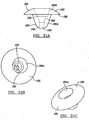
- Figure 3a shows another configuration, which has a cavity 52 defined in the shelf member 44.
- the cavity 52 is preferably the female side of a Morse taper, which would engage a male Morse taper on the head member 33.
- Figure 3b shows the head member 33 which mates with the base member 32 of Figure 3a .
- a surgical kit of the components would contain numerous head members 33, each having a varied radius of curvature, diameter, and height to allow a surgeon to optimize joint movement. Additionally, a surgical kit would contain the instruments needed for implantation (shown later).
- the head member 33 and base member 32 must be made of bio-compatible materials such as, without limitation, titanium, titanium alloys, surgical alloys, stainless steels, bio-compatible ceramics, and cobalt alloys.
- the base member 32 can additionally be made of materials such as biocompatible ceramics and resorbable and non-resorbable polymers and other anticipated bio-compatible metallic or polymeric materials. Should the base member 32 be made of non-metallic components, a fastener would be needed to couple the head 33 to the base 32.
- the shelf members 44 need not to be planar.
- Figures 4 and 5 show the base member 32 and having an interior concave surface 56 and a convex medial surface 58.
- Base members, as disclosed in Figures 4 and 5 would be used in situations where maximum bone removal in the humerus 38 is required.
- the head member 33 would have a convex medial surface 59 for engaging the concave surface 56. It is envisioned as with all of the configurations that the base members 32 and head member 33 can be coupled using the mating member 48, i.e., Morse taper.
- the use of the convex-concave interface provides a coupling interface which is self centering under a multitude of loading conditions.
- the interface reduces the occurrence of micro-motions which can disrupt the normal functioning of the joint prosthesis as well as lead to premature component failures. Any loads applied to the articulating surface of the head member 33, are transferred as a perpendicular force into the base member 32 of the modular humeral component 31 through the non-planar shelf member 44.
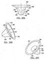
- Figures 6 and 7 define base members 32 having the shelf member 60 having a convex outer surface 62. Additionally shown is a concave inner surface 64 for mating with a resected head 36 of the humerus 38.
- the base members as depicted in Figures 6 and 7 can be used when minimal bone removal is possible and will generally encapsulate the hemispheric shape cut into the humerus 38 as described later.
- any loads applied to the articulating surface of the head member 33 are transferred as a perpendicular force into the base member 32 of the modular humeral component 31.
- Figures 8 and 9 disclose alternate configurations of the base member 32 for the humeral component 31.
- Figure 8 depicts the base member 32 having a convex outer surface 66 and a flat lateral surface 68.
- the base members as depicted in Figures 2a-3 and 8 can be utilized when a moderate amount of bone material must be removed from the resected head 36 of the humerus 38.
- Figure 9 depicts the base member 32 having a flat upper surface 51 and a convex lateral surface 58. This base member would readily utilize the head member 33 as used with the base member as depicted in Figure 2a . It is envisioned that either base member can have a defined male or female mating member 48 in the form of a Morse taper.
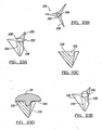
- Figures 10-12 depict possible configurations for the fixation peg 34.
- Figure 10 shows the fixation peg 34 defining a plurality of flutes 70 therein.
- the modular system does not need a shelf member 44. Without the shelf member 44, the base can have either a male or female Morse taper.
- Figures 11 and 12 depict the fixation peg 34 being at a tapered prism with the base of the prism coupled to the lower lateral surface 50 of the shelf member 44.
- Figures 13 and 14 depict possible surface treatments for the lower lateral surface 50 of the shelf member 44 and fixation peg 34.
- All of the possible fixation pegs 34 can have a porous coated region 72, which will assist in the fixation of the component to the humerus 38.
- all of the lower lateral surfaces 50 of the shelf member 44 can define a waffle pattern 74 to assist in the incorporation of bone cement.
- Each fixation peg 34 extends from the lower lateral surface 50 to define or fill in a coupling region 75 having a diameter of about 0.50 inches.
- Each coupling region 75 also includes a sidewall 77 formed with and from the lower lateral surface 50.
- the coupling region 75 provides a smooth flat surface for which the fixation peg 34 extends out, and reduces or eliminates any stress risers about each fixation peg 34, which could be caused by positioning the lower lateral surface 50 immediately adjacent the fixation peg 34.
- the fixation peg 34 includes a first end 79, which is inserted into or engages a cavity or hole formed within a cavity in the humerus and a second end 81, which extends from or is integral with the shelf member 44.
- the first end 79 is semi-spherical and the second end has a 0.25 inch radius about the circumference of the second end 81 of the peg, which blends into a flat or smooth portion of the coupling region 75 to decrease the overall sheer stress of the fixation peg 34.
- embedded within the first end of each fixation peg 34 is a tantalum ball 83.
- the tantalum ball 83 enables the humeral component 31 to be easily identified in an x-ray.
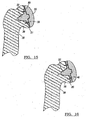
- Figures 15 and 16 depict cross-sectional views of various components implanted into resected head 36 of humerus 38.
- the base member 32 as depicted in Figure 9 can be used.
- the base member 32 is fixed to the humerus 38 using a plurality of screws 85.
- the lateral surface 59 of the head member 33 defines a cavity 52 for receiving the mating member 48 or Morse taper post.
- the base member 32 is held to the humerus 38 by use of screws 85 disposed through the holes 46.
- Figure 16 discloses the use of the base member 32 as depicted in Figure 3a which is similarly held in place by use of fixation screws 85 to the humerus 38.
- FIGS 17 through 18 show an alternate configuration of the humeral component 109.
- Base member 110 is shown having a modified Morse taper cavity 116.
- the humeral component 109 further has a head portion 112 with a male Morse taper portion 121.
- Disposed between the head portion 112 and the base member 110 is a coupling member 114.
- Coupling member 114 has an outer surface 118 which acts as the male portion of a Morse taper to bond with the cavity 116 of the base member 110.
- Coupling member 114 further defines a female portion 120 of a Morse taper which corresponds to the male portion 121 of the Morse taper of the head portion 112.
- the coupling portion 114 functions to move the center of curvature of the head portion 112 a fixed distance 123 from the center line of the base member 110. This functions to effectively change the centering location of the head portion 112 with respect to the humerus 138, thus allowing the surgeon more flexibility.
- Figure 17a shows the alternate humeral component 109 in its assembled configuration.
- Figure 18 shows an exploded view of the alternate humeral component 109, coupling member 114, and base member 110. Rotation of coupling member 114 allows for translation of the head portion 112 on the base member 110.
- Figures 19 through 19b depict a head portion 112 having a female Morse taper cavity 116 which engages a male Morse taper 115 on alternate coupling member 114.
- Figure 19a depicts an assembled view of the alternate humeral component 109.
- Figures 21 through 21 b depict an alternate configuration of the humeral component 122. Shown is the base member 124 which has a modified female cavity defining a Morse taper 116.
- the head portion 126 has a coupling male Morse taper 132 disposed on the medial surface of the head component 126. Disposed between the head portion 126 and the base portion 124 is the coupling member 128.
- the coupling member 128 defines an outer surface 118 which functions as the male portion of the Morse taper and couples to the female portion 116 of the base member 124.
- the coupling member 128 further defines an interior cavity 130 which functions as a female Morse taper for the male Morse taper 132 of the head 126.
- the interior cavity 130 of the coupling member has an offset angle 134, which functions to rotate the center of curvature of the head portion 126 with respect to the base member 124.
- Figures 20 and 22 show the alternate humeral components 122 inserted into a resected humerus. As with the other humeral components, the base member is fixed to the head of the humerus using fasteners.
- FIGS 23a-23e depict another alternate configuration of components. Shown is a shelfless base member 232 which is formed by a fixation peg 234. Each fixation peg 234 has three evenly spaced triangular fins 236 disposed thereon. The triangular fins 236 have an edge 239 which is coplanar to a top surface 238 of fixation peg 234. Incorporated into a top surface 238 of the fixation peg 234 is a fixing mechanism 240.
- Figures 23a and 23b disclose fixing mechanism 240 in the form of a female Morse taper as the fixation which functions to couple the head 30 onto the base member 232 (see Figure 23d ).
- the top surface 238 alternately can have a fixing mechanism 240 in the form of a male Morse taper disposed thereon.
- a head member 30 being used in this configuration can have a lower surface 244 which has a porous coat, plasma spray, grit blast, or smooth surface to facilitate the coupling to the bone.
- the base member 240 When the base member 240 is coupled to head member 30, there is a defined gap between the lower surface 244 of the head 30 and the upper surface 238 of the base member 232. After implantation, the lower surface 244 of head member 30 rests upon the resected bone, not the top surface 238 of the base member 232.
- the method for implanting the humeral component 31, along with associate surgical components utilized will now be described with reference to Figures 24a-28 .
- the head of the humerus 38 is resected using a saw, chisel then planed flat or with a concavity. With the resected head 36 of the humerus 38 exposed, an alignment or guide hole 90 is first drilled substantially through the center of resected head 36 of the humerus 38 using a quick release drill bit 96 and driver 98. Optionally, the resected head 36 of humerus 38 can be resected to provide a flat surface during the drilling of pilot hole 90.
- the resected head 36 of humerus 38 is optionally reamed using a concave spherical reamer shaft 102 with the driver 98.
- the concave reamer 102 includes a guide pin 104 and a roughened spherical surface 106 substantially corresponding to the spherical shape of the lower medial surface of the shelf member 44 of base member 32.
- An optional convex reamer surface 108 permits rasping or drilling of tight humeral cavities (see Figures 26a and 26b ).
- the bone of the resected head 36 of the humerus 38 is prepared to mate or conform to the shape of the lower lateral surface 50 of the shelf member 44 of the base member 32.
- the reamer 102 can have a convex shape or alternatively a flat shape, which reams a concave shape into the resected head 36 of the humerus 38. Determining which reamer is used is a function of the preoperative degenerative changes in the humerus 38.
- the optional screws 85 are disposed through the holes 46 to couple the base member 32 to the humerus 38.
- a surgeon may use any number of test head portions and/or adapter portions to determine the proper size needed to mate with the glenoid component. Once a proper head member 33 size has been determined, the final head member 33 can be fixed to the shelf member 44 of the base member 32.
- Figures 26 and 27 show the use of the base member 32 as depicted in Figure 3 . As can be seen, the base member of Figure 3 is utilized when a minimal amount of bone is required to be removed.
- Figures 29a-c represent side and perspective views of an alternate fixation member 246 defining a through member fixation bore 248.
- the shelf member 250 can have at least one mating member 252 for engaging the head member of the humeral component.
- the mating member 252 can be a defined female Morse taper 254 or other suitable attaching mechanism.
- each fixation member 246 has a fixation peg 256 disposed on the lower lateral surface 258 of shelf member 250.
- the fixation peg 256 may be perpendicular to the shelf member for the entire length of the fixation peg 256.
- the shelf member 250 of the fixation member 246 can define a convex spherical lower lateral surface 258 and concave spherical upper lateral surface 260.
- Figure 29a shows hidden lines representing the through member fixation bore 248.
- the female Morse taper 254 is optionally co-linear or concentric with both the through member fixation bore 248 and the fixation peg 256.
- Adjacent to the bottom 262 of the female Morse taper is a defined conical portion 264 which is configured to accept a head of a bone coupling screw.
- Figures 30a-c represent side and perspective views of an alternate fixation member 266 having a mating member 268 in the form of a male Morse taper with a through stem fixation bore 270 for engaging the head member of the humeral component.
- the fixation member 266 has a fixation peg 272 disposed on the lower lateral surface 274 of shelf member 276.
- the shelf member 276 can define convex spherical lower lateral surface 258 and concave spherical upper lateral surface 260.
- Figure 30a shows hidden lines representing the through member fixation bore 270.
- the mating member 268, in the form of a Morse taper, is optionally co-linear with both the through member fixation bore 270 and the fixation peg 272. Disposed through the top 278 of the fixation member 268 is a defined conical portion 280 which is configured to accept a tapered head of a bone coupling screw.
- Figures 31 a-c and 32a-c represent side and perspective views of an alternate fixation members 282a and 282b.
- the members 282a and 282b have a shelf member 280 with mating features 284a and 284b for engaging the head member of the humeral component.
- the shelf member 280 of the fixation members 282a and 282b define a flat lower lateral surface 286 and convex spherical upper lateral surface 288.
- Figures 31a and 32a show hidden lines representing the through member fixation bore 290.
- the mating features 284a and 284b in the form of a Morse tapers are optionally co-linear with both the through member fixation bore 290 and a fixation peg 292.
- a fixation bore 248 Disposed through the top 278 of the mating features 284a and 248b and fully though the fixation members 282a and 282b is a defined fixation bore 248 having a conical screw head supporting portion 298 which is configured to accept a tapered head of a bone coupling screw.
- This bone coupling screw can be positioned into or extended through the resected bone.
- fixation members depicted in figures 29a through 32c are generally implanted as described above. Generally, a portion of the head of the joint is resected using a rasp or other appropriate cutting tool. A bore is then formed in the resected head. The fixation member is then fixed to the prepared surface. A fastener such as a bone screw then disposed through the fixation bore 290 to fasten the fixation member to the resected bone. At this point, a articulating head (shown in figures 1 or 15 through 22 ) is coupled to the fixation member. While specific fixation members are show in figures 29-32c , the through bore feature is equally applicable to the fixation members shown in figure 1-14 .
- the modular nature of the humeral component 31 allows a set of various types of both replacement base members 32 and head members 33 to be formed. In using such a set, a surgeon can interoperably choose the appropriate base member depending on the patient's particular degenerative condition. Additionally, the surgeon can then choose from a set of head members 33, which both have the proper articulating surface radius and a proper coupling to the base member 32.
- Figures 33 and 34 represents a perspective and cross sectional views of an alternate fixation member 300.
- the fixation member 300 is formed of two components, a generally circular shelf member 302, and a bone engaging member 304. As described below, after an articulating surface is resected, an appropriate shelf member 302 is positioned against the resected surface. The bone engagement member 304 is then coupled to and through the shelf member 302 into the resected bone. An articulating head (not shown) is coupled to the bone fixation member to form a prosthetic with an articulating surface.
- the bone engaging member 304 has a head engagement portion 306 and a threaded bone engagement portion 308.
- the bone engagement member 304 additionally has a shelf member engagement region 310 and drive feature 312.
- the shelf engagement region 310 functions to distribute and translate forces from the articulating head into the resected bone. It is envisioned that the shelf engagement region 310 can be an annular engagement flange 318 or textured cylindrical interface surface.
- the drive feature 312 can be an aperture having at least one defined flat drive surface, such as a hex aperture.
- the head engagement portion 306 can be a defined male 314 or female 316 Morse taper.
- the shelf member 302 can be generally flat or curved. As described in previous arrangements, the shelf member 302 has upper and lower surfaces 320 and 322 which can be flat, concave or convex.
- the shelf members can additionally define a plurality of through apertures 324 that are configured to accept bone engaging screws to prevent rotation of the shelf member 302 during the insertion of the bone engaging member.
- Figure 34 shows the annular engagement flange 318 is positioned an upper surface 320 of the annular shelf member 302.
- the shelf member 302 defines an aperture which annularly supports the bone engaging member 304. It is envisioned that the male Morse taper 316 can be used to couple the fixation member to an articulating head (see Figures 15-21 ).
- Figure 35 represents a cross-sectional view of an alternate fixation member 302. Shown is the bone engaging member 304 having a head engagement portion 306 which is generally located below the shelf member 302.
- the head engagement portion 306 is shown as a female Morse taper 316.
- the annular engagement flange 318 is disposed within an annular coupling groove 326 which is formed about the aperture 328 of the shelf member 302. Defined in the bottom of the Female Morse taper 316 is the drive mechanism 312. It is envisioned that the annular coupling groove 326 can take the form of a tapered countersink.
- Figures 36a and 36b represent an alternate fixation component having a bone fixation member 304.
- the upper surface 320 of the shelf member 302 is show being concave as previously described.
- the shelf member has a annular coupling groove 326 which mates with the annular flange 318 of the bone engaging member 304.
- Figure 37 represents a cross-sectional view of an alternate fixation member. Shown is the bone engaging member 304 having a head engagement portion 306 which is generally located below the shelf member 302.
- the head engagement portion 306 is shown as a female Morse taper 316.
- the annular engagement flange 318 is disposed on the upper surface 320 about the aperture 328 of the shelf member 302 Defined in the bottom of the Female Morse taper 316 is the drive mechanism 312.
- Figure 38 shows the bone engagement member 304 with annular engagement flange 318.
- the annular engagement flange 318 is positioned on the convex upper surface 320 of the annular shelf member 302.
- the shelf member 302 defines an annular engagement groove adjacent the aperture which annularly supports the male Morse taper of the bone engaging member 304.
- Figure 39a-39b represents the implantation of a fixation member.
- the bone engagement member 302 is rotated until the annular engagement flange 318 engages the upper surface 320 of the annular shelf member 302.
- Optional screws 85 are disposed through the holes 324 to couple the base member 302 to the humerus 38.
- a surgeon may use any number of test head portions and/or adapter portions to determine the proper size needed to mate with the glenoid component.
- the final head member 330 can be fixed to the head engagement portion 306 of the bone engaging member 302.
- Figure 40 represents a humeral implant 400 according to another embodiment. Shown is a coupling member 402 and a humeral head 403.
- the coupling member 402 has a generally cylindrical body portion 404 with an exterior coupling surface 406.
- the coupling surface 406 can be tapered or can be cylindrical.
- the exterior coupling surface 406 further has at least one bone engaging thread 407 which is configured to couple the cylindrical body portion to a hole defined within the receptive humerous as previously described.
- Appended to the proximal end 408 of the body portion 404 is a pair of linearly aligned coupling flanges 410 and 412, which define a pair of fastening member coupling apertures 414.
- the body portion 404 defines a female Morse taper 416 which is used to couple the head 403 to the coupling member 402.
- the coupling member 402 is configured to allow the fixation of the head without relying on the head seating on the resection for stability.
- the head portion 403 is shown with an axially centered fixation stem 418. It is envisioned the stem 418 can take the form of an offset male Morse taper as is shown in Figures 17-22 . Additionally, the head has an exterior articulation surface 405 which is configured to articulate with a natural or prosthetic glenoid (not shown).
- Figures 41 and 42 represent side views of the prosthetic shown in Figures 40 .
- the coupling flanges 410 and 412 have a coupling surface 420 which is configured to be mated to a resected humerus 422.
- the resected humerus 422 can be prepared as previously described to have a flat 424 or convex surface 426.
- the body 404 is inserted into a hole within the resected humerus 422. In this regard, the body 404 is rotated in a hole formed in the resected humerus to engage the threads with the humeral head and neck bone.
- a pair of fasteners 434 are positioned through the coupling apertures 414 in the coupling flanges 410 and 412.
- a coupling surface 420 of the flanges 410 and 412 can have a predefined concave coupling surface. Additionally, the concave surface can be formed by a physician bending the flanges 410 and 412 in the operating room prior to the insertion of the coupling fasteners 434 into the apertures 414.
- a trialing head 60' is optionally used to determine the proper size and orientation of the humeral head 403.
- the humeral head 403 is then coupled to the coupling member as previously described.
Description
- This application is a continuation-in-part application of United States Patent Application No.
10/930,044 filed on August 30, 2004 10/205,386 filed July 25, 2002 U.S. Patent No. 6,783,549 , which claims the benefit ofU.S. Provisional Application No. 60/308,340, filed on July 27, 2001 - This invention relates generally to an apparatus and method for shoulder arthroplasty and, more particularly, to a humeral component and other associated surgical components and instruments for use in shoulder arthroplasty.
- A natural shoulder joint may undergo degenerative changes due to a variety of etiologies. When these degenerative changes become so far advanced and irreversible, it may ultimately become necessary to replace a natural shoulder joint with a prosthetic shoulder joint. When implantation of such a shoulder joint prosthesis becomes necessary, the natural head portion of the humerus is resected and a cavity is created in the intramedullary canal of the host humerus for accepting a humeral component. The humeral component includes a head portion used to replace the natural head of the humerus. Once the humeral component has been implanted, the humeral cavity positioned at the scapula socket may also be resurfaced and shaped to accept a glenoid component. The humeral component generally includes an articulating surface which engages and articulates with the socket portion of the glenoid component.
- It is generally known in the art to provide a shoulder joint prosthesis having a humeral component, as discussed above. However, current prior art humeral components along with the associated surgical components and instruments utilized during shoulder arthroplasty suffer from many disadvantages.
- For example, since the humeral component is subject to various types of loading by the glenoid component, the humeral component must offer a stable and secure articulating surface. To achieve this, some humeral components provide a post or stem attached to a lateral surface of the prosthetic humeral head. These humeral components are generally a single piece system with a single stem, which is inserted and cemented into a hole bored deeply into the intramedullary cavity. However, such existing humeral components also exhibit several disadvantages. For example, these types of stemmed humeral components utilize a large stem to stabilize and secure the humeral component to the humerus. Such humeral components increase the amount of bone tissue removed, while also increasing the labor and complexity of the shoulder arthroplasty. Other stemmed humeral components may offer a larger diameter stem. However, the larger diameter stem also requires excess bone tissue to be removed which may not be practical in some patients.
- Other prior art humeral components, such as that disclosed in
WO 01/67988 A2 - Additionally, most prior art humeral components only rely on the stem to secure the humeral component into the intramedullary canal, via a cement mantle or bone attachment. The stem may also include grooves or holes, which act as an anchor, once the stem is cemented within the intramedullary canal. The medial surface of most humeral components are thus generally overlooked to enhance cement fixation and are therefore generally smooth. Although some humeral components may include a few longitudinal grooves and others may include both grooves and depressions on the medial surface, such surface enhancements only utilize or texture a portion of the medial surface, thereby not advantageously using the entire medial surface.
-
FR 2704747 -
EP1591084A1 discloses an implant having a support comprising a shield extending its lower edge and designed to cover a portion of a scapula at an anchoring zone of a triceps tendon. The support has a rear side and a front side forming an angle between 5 to 15 degrees. The support is intended to be implanted in the scapula. - What is needed then is a modular humeral component and associated surgical components for use in shoulder arthroplasty which do not suffer from the above-mentioned disadvantages. This in turn, will provide a humeral component which is stable and secure, reduces the overall amount of bone tissue required to be removed, increases a surgeon's available components utilizing a single sized post, reduces the overall surgical time and complexity, increases overall medial surface area, enhances and increases post strength without increasing overall post diameter, provides a fully enhanced or textured medial surface for enhanced cement fixation or bone fixation and increased overall stability, provides for a uniform cement mantle, and provides increased tensile and shear strength. It is, therefore, an object of the present invention to provide such a humeral component and associated surgical components for use in shoulder arthroplasty.
- In accordance with the teachings of the present invention, an apparatus and method for shoulder arthroplasty is disclosed. The apparatus and method employs a modular humeral component and other associated surgical components for use in the shoulder arthroplasty. In this regard, the modular humeral component is adapted to be implanted into a humerus and engaged by a glenoid portion of a scapular component.
- According to the present invention, there is provided a modular humeral component having the features of claim 1.
- In one preferred embodiment, a modular humeral component is used for shoulder arthroplasty such that the humeral component is adapted to be implanted into a humerus and engage a glenoid component. The humeral component includes a head member having a first articulating surface and a second fixation surface, which is opposite to the first articulating surface. The first articulating surface is adapted to engage, the articulating surface of the glenoid component and the second fixation surface is adapted to engage a fixation component. The fixation component has a first surface adapted to be secured to the head member and a second surface that is generally opposite the first surface. The second surface includes a fixation member adapted to be secured to the humerus.
- Use of the present invention provides an apparatus and method for shoulder arthroplasty, and specifically, a modular humeral component and associated surgical components for use in shoulder arthroplasty. As a result, the aforementioned disadvantages associated with the currenfily available humeral components and associated surgical components for shoulder arthroplasty have been substantially reduced or eliminated.
- Still other advantages of the present invention will become apparent to those skilled in the art after reading the following specification and by reference to the drawings in which:
-
Figure 1 is a perspective view of a humeral component shown implanted in a skeletal structure; -
Figures 2a-2c are views of the fixation member of humeral component ofFigure 1 ; -
Figures 3a-9 are alternate configurations of fixation member for a humeral component; -
Figures 10-12 represent alternate peg configurations for a fixation member of a humeral component; -
Figures 13 and 14 represent alternate texturing, which is usable in the humeral components ofFigures 1 to 12 ; -
Figures 15 and 16 represent cross-sectional views of implanted humeral components; -
Figures 17 through 22 depict an alternate configuration having an insert member disposed between the head and the base member; -
Figures 23a-23e depict another alternate configuration having flanges disposed on a shelfless base member; -
Figures 24-26b illustrate a method for preparing a humerus for implantation of a humeral component using associated surgical components; -
Figures 27-28 further illustrate methods for implanting humeral components into a prepared humerus; -
Figures 29a-c represent side and perspective views of an alternate fixation member having a through stem fixation bore; -
Figures 30a-c represent side and perspective views of an alternate fixation member having a male Morse taper with through stem fixation bore; -
Figures 31a-c represent side and perspective views of an alternate fixation member having a female Morse taper with through stem fixation bore; -
Figures 32a-c represent side and perspective views of an alternate fixation member -
Figure 33 represents a perspective view of an alternate fixation member; -
Figure 34 represents a cross-sectional view of the fixation member shown infigure 33 ; -
Figure 35 represents a cross-sectional view of an alternate fixation member; -
Figures 36a and 36b represent an alternate fixation component having a fixation member; -
Figure 37 represents the coupling of a bone engagement member to a fixation shelf; -
Figure 38 represents a fixation member having a concave shelf member; -
Figure 39a-39b represents the intention of a fixation member; -
Figure 40 represents a prosthetic according to an embodiment to the invention; -
Figures 41 and 42 are side views of the prosthetic shown inFigure 40 ; -
Figure 43 represents a perspective view of the implantation of the coupling member shown inFigure 40 ; and -
Figures 44 and 45 represent side views of the implantation of a humeral prosthetic head into the coupling member shown inFigures 43 and 42 . - The following description of the preferred embodiments concerning an apparatus and method for shoulder arthroplasty is merely exemplary in nature and is in no way intended to limit the invention, its application, or uses.
-
Figure 1 depicts components used in a shoulder arthroplasty. As shown, the modularhumeral component 31 has abase member 32 and ahead member 33. Thebase member 32 has afixation peg 34, which is used to attach the humeral component to the resectedportion 36 of thehumerus 38. If a total shoulder arthroplasty is performed, aglenoid component 40 is first implanted into thescapula 42 using techniques well known in the art. Theglenoid component 40 is preferably of the type disclosed inU.S. Patent No. 5,800,551 , or other suitable conventional glenoid components. Thehumeral component 31 is designed to allow rotational and transitional movement of thehead member 33 with respect to theglenoid component 40. -
Figures 2a-2c depict abase member 32. Thebase member 32 is defined by ashelf member 44, which may have a plurality of throughholes 46. Theshelf member 44 can have at least onemating member 48 for engaging thehead member 33 of thehumeral component 31. It is preferred that themating member 48 be a defined Morse taper or other suitable attaching mechanism. In addition to themating member 48, eachbase member 32 has afixation peg 34 disposed on the lowerlateral surface 50 ofshelf member 44. Thefixation peg 34 is generally perpendicular to the shelf member for its entire length of thefixation peg 34. As depicted inFigures 2a-3 , theshelf member 44 of thebase member 32 can define flat lowerlateral surface 50 and flat generally parallel upper surfaces 51.Figure 3a shows another configuration, which has acavity 52 defined in theshelf member 44. Thecavity 52 is preferably the female side of a Morse taper, which would engage a male Morse taper on thehead member 33. -
Figure 3b shows thehead member 33 which mates with thebase member 32 ofFigure 3a . It should be noted that a surgical kit of the components would containnumerous head members 33, each having a varied radius of curvature, diameter, and height to allow a surgeon to optimize joint movement. Additionally, a surgical kit would contain the instruments needed for implantation (shown later). - The
head member 33 andbase member 32 must be made of bio-compatible materials such as, without limitation, titanium, titanium alloys, surgical alloys, stainless steels, bio-compatible ceramics, and cobalt alloys. Optionally, thebase member 32 can additionally be made of materials such as biocompatible ceramics and resorbable and non-resorbable polymers and other anticipated bio-compatible metallic or polymeric materials. Should thebase member 32 be made of non-metallic components, a fastener would be needed to couple thehead 33 to thebase 32. - As shown in
Figures 4-7 , theshelf members 44 need not to be planar.Figures 4 and 5 show thebase member 32 and having an interiorconcave surface 56 and a convexmedial surface 58. Base members, as disclosed inFigures 4 and 5 would be used in situations where maximum bone removal in thehumerus 38 is required. In each situation, thehead member 33 would have a convexmedial surface 59 for engaging theconcave surface 56. It is envisioned as with all of the configurations that thebase members 32 andhead member 33 can be coupled using themating member 48, i.e., Morse taper. The use of the convex-concave interface provides a coupling interface which is self centering under a multitude of loading conditions. The interface reduces the occurrence of micro-motions which can disrupt the normal functioning of the joint prosthesis as well as lead to premature component failures. Any loads applied to the articulating surface of thehead member 33, are transferred as a perpendicular force into thebase member 32 of the modularhumeral component 31 through thenon-planar shelf member 44. -
Figures 6 and 7 definebase members 32 having theshelf member 60 having a convexouter surface 62. Additionally shown is a concaveinner surface 64 for mating with a resectedhead 36 of thehumerus 38. The base members as depicted inFigures 6 and 7 can be used when minimal bone removal is possible and will generally encapsulate the hemispheric shape cut into thehumerus 38 as described later. As with the base members as shown infigures 4 and 5 , any loads applied to the articulating surface of thehead member 33, are transferred as a perpendicular force into thebase member 32 of the modularhumeral component 31. -
Figures 8 and 9 disclose alternate configurations of thebase member 32 for thehumeral component 31.Figure 8 depicts thebase member 32 having a convexouter surface 66 and a flatlateral surface 68. The base members as depicted inFigures 2a-3 and 8 can be utilized when a moderate amount of bone material must be removed from the resectedhead 36 of thehumerus 38.Figure 9 depicts thebase member 32 having a flatupper surface 51 and a convexlateral surface 58. This base member would readily utilize thehead member 33 as used with the base member as depicted inFigure 2a . It is envisioned that either base member can have a defined male orfemale mating member 48 in the form of a Morse taper. -
Figures 10-12 depict possible configurations for thefixation peg 34.Figure 10 shows thefixation peg 34 defining a plurality offlutes 70 therein. As can be seen, the modular system does not need ashelf member 44. Without theshelf member 44, the base can have either a male or female Morse taper.Figures 11 and 12 depict thefixation peg 34 being at a tapered prism with the base of the prism coupled to the lowerlateral surface 50 of theshelf member 44. -
Figures 13 and 14 depict possible surface treatments for the lowerlateral surface 50 of theshelf member 44 andfixation peg 34. All of the possible fixation pegs 34 can have a porouscoated region 72, which will assist in the fixation of the component to thehumerus 38. Additionally, all of the lower lateral surfaces 50 of theshelf member 44 can define awaffle pattern 74 to assist in the incorporation of bone cement. Eachfixation peg 34 extends from the lowerlateral surface 50 to define or fill in a coupling region 75 having a diameter of about 0.50 inches. Each coupling region 75 also includes asidewall 77 formed with and from the lowerlateral surface 50. The coupling region 75 provides a smooth flat surface for which thefixation peg 34 extends out, and reduces or eliminates any stress risers about eachfixation peg 34, which could be caused by positioning the lowerlateral surface 50 immediately adjacent thefixation peg 34. - The
fixation peg 34 includes afirst end 79, which is inserted into or engages a cavity or hole formed within a cavity in the humerus and a second end 81, which extends from or is integral with theshelf member 44. Thefirst end 79 is semi-spherical and the second end has a 0.25 inch radius about the circumference of the second end 81 of the peg, which blends into a flat or smooth portion of the coupling region 75 to decrease the overall sheer stress of thefixation peg 34. Optionally, should the fixation peg be non-metallic, embedded within the first end of eachfixation peg 34 is a tantalum ball 83. The tantalum ball 83 enables thehumeral component 31 to be easily identified in an x-ray. -
Figures 15 and 16 depict cross-sectional views of various components implanted into resectedhead 36 ofhumerus 38. As depicted inFigure 16 , when a large amount of bone mass must be removed during the arthroplasty, thebase member 32 as depicted inFigure 9 can be used. As is shown, thebase member 32 is fixed to thehumerus 38 using a plurality ofscrews 85. Thelateral surface 59 of thehead member 33 defines acavity 52 for receiving themating member 48 or Morse taper post. - As with the base member depicted in
Figure 15 , thebase member 32 is held to thehumerus 38 by use ofscrews 85 disposed through theholes 46.Figure 16 discloses the use of thebase member 32 as depicted inFigure 3a which is similarly held in place by use of fixation screws 85 to thehumerus 38. -
Figures 17 through 18 show an alternate configuration of thehumeral component 109.Base member 110 is shown having a modifiedMorse taper cavity 116. Thehumeral component 109 further has ahead portion 112 with a maleMorse taper portion 121. Disposed between thehead portion 112 and thebase member 110 is acoupling member 114. Couplingmember 114 has anouter surface 118 which acts as the male portion of a Morse taper to bond with thecavity 116 of thebase member 110. Couplingmember 114 further defines afemale portion 120 of a Morse taper which corresponds to themale portion 121 of the Morse taper of thehead portion 112. Thecoupling portion 114 functions to move the center of curvature of the head portion 112 a fixed distance 123 from the center line of thebase member 110. This functions to effectively change the centering location of thehead portion 112 with respect to the humerus 138, thus allowing the surgeon more flexibility. -
Figure 17a shows the alternatehumeral component 109 in its assembled configuration.Figure 18 shows an exploded view of the alternatehumeral component 109,coupling member 114, andbase member 110. Rotation ofcoupling member 114 allows for translation of thehead portion 112 on thebase member 110.Figures 19 through 19b depict ahead portion 112 having a femaleMorse taper cavity 116 which engages amale Morse taper 115 onalternate coupling member 114.Figure 19a depicts an assembled view of the alternatehumeral component 109. -
Figures 21 through 21 b depict an alternate configuration of thehumeral component 122. Shown is thebase member 124 which has a modified female cavity defining aMorse taper 116. Thehead portion 126 has a couplingmale Morse taper 132 disposed on the medial surface of thehead component 126. Disposed between thehead portion 126 and thebase portion 124 is thecoupling member 128. Thecoupling member 128 defines anouter surface 118 which functions as the male portion of the Morse taper and couples to thefemale portion 116 of thebase member 124. Thecoupling member 128 further defines aninterior cavity 130 which functions as a female Morse taper for themale Morse taper 132 of thehead 126. Theinterior cavity 130 of the coupling member has an offsetangle 134, which functions to rotate the center of curvature of thehead portion 126 with respect to thebase member 124. Similarly, shown inFigure 21b is acoupling member 114 having amale Morse taper 115 being angled. -
Figures 20 and 22 show the alternatehumeral components 122 inserted into a resected humerus. As with the other humeral components, the base member is fixed to the head of the humerus using fasteners. -
Figures 23a-23e depict another alternate configuration of components. Shown is ashelfless base member 232 which is formed by afixation peg 234. Eachfixation peg 234 has three evenly spacedtriangular fins 236 disposed thereon. Thetriangular fins 236 have anedge 239 which is coplanar to atop surface 238 offixation peg 234. Incorporated into atop surface 238 of thefixation peg 234 is afixing mechanism 240. -
Figures 23a and 23b disclose fixingmechanism 240 in the form of a female Morse taper as the fixation which functions to couple thehead 30 onto the base member 232 (seeFigure 23d ). As can be seenFigure 23e , thetop surface 238 alternately can have afixing mechanism 240 in the form of a male Morse taper disposed thereon. It is envisioned that ahead member 30 being used in this configuration can have alower surface 244 which has a porous coat, plasma spray, grit blast, or smooth surface to facilitate the coupling to the bone. - When the
base member 240 is coupled tohead member 30, there is a defined gap between thelower surface 244 of thehead 30 and theupper surface 238 of thebase member 232. After implantation, thelower surface 244 ofhead member 30 rests upon the resected bone, not thetop surface 238 of thebase member 232. - The method for implanting the
humeral component 31, along with associate surgical components utilized will now be described with reference toFigures 24a-28 . The head of thehumerus 38 is resected using a saw, chisel then planed flat or with a concavity. With the resectedhead 36 of thehumerus 38 exposed, an alignment or guidehole 90 is first drilled substantially through the center of resectedhead 36 of thehumerus 38 using a quickrelease drill bit 96 anddriver 98. Optionally, the resectedhead 36 ofhumerus 38 can be resected to provide a flat surface during the drilling ofpilot hole 90. - Once the
guide hole 90 is drilled, the resectedhead 36 ofhumerus 38 is optionally reamed using a concavespherical reamer shaft 102 with thedriver 98. Theconcave reamer 102 includes aguide pin 104 and a roughenedspherical surface 106 substantially corresponding to the spherical shape of the lower medial surface of theshelf member 44 ofbase member 32. An optionalconvex reamer surface 108 permits rasping or drilling of tight humeral cavities (seeFigures 26a and 26b ). Upon rotating the surface of the reamer, the bone of the resectedhead 36 of thehumerus 38 is prepared to mate or conform to the shape of the lowerlateral surface 50 of theshelf member 44 of thebase member 32. As depicted inFigures 25a and 26b , thereamer 102 can have a convex shape or alternatively a flat shape, which reams a concave shape into the resectedhead 36 of thehumerus 38. Determining which reamer is used is a function of the preoperative degenerative changes in thehumerus 38. - With reference to
Figures 27-28 , which depict the insertion of thehumeral components 30, once the surface of the resectedhead 36 of thehumerus 38 has been resected, thebase member 32 is inserted into theguide hole 90. It is envisioned that fixation peg 34 of thebase member 32 can be forced into theguide hole 90 to displace the bone material around the intramedullary canal. Optionally, theguide hole 90 can also be reamed to a larger interior diameter to accept thebase member 32 without displacement of the bone material by thefixation peg 34. - Once the
base member 32 has been inserted into theguide hole 90, theoptional screws 85 are disposed through theholes 46 to couple thebase member 32 to thehumerus 38. At this point, a surgeon may use any number of test head portions and/or adapter portions to determine the proper size needed to mate with the glenoid component. Once aproper head member 33 size has been determined, thefinal head member 33 can be fixed to theshelf member 44 of thebase member 32. -
Figures 26 and27 show the use of thebase member 32 as depicted inFigure 3 . As can be seen, the base member ofFigure 3 is utilized when a minimal amount of bone is required to be removed. -
Figures 29a-c represent side and perspective views of analternate fixation member 246 defining a through member fixation bore 248. Theshelf member 250 can have at least onemating member 252 for engaging the head member of the humeral component. Themating member 252 can be a definedfemale Morse taper 254 or other suitable attaching mechanism. In addition to themating member 252, eachfixation member 246 has afixation peg 256 disposed on the lowerlateral surface 258 ofshelf member 250. Thefixation peg 256 may be perpendicular to the shelf member for the entire length of thefixation peg 256. As depicted inFigures 29a-c , theshelf member 250 of thefixation member 246 can define a convex spherical lowerlateral surface 258 and concave spherical upperlateral surface 260.Figure 29a shows hidden lines representing the through member fixation bore 248. As shown, thefemale Morse taper 254 is optionally co-linear or concentric with both the through member fixation bore 248 and thefixation peg 256. Adjacent to thebottom 262 of the female Morse taper is a definedconical portion 264 which is configured to accept a head of a bone coupling screw. -
Figures 30a-c represent side and perspective views of analternate fixation member 266 having amating member 268 in the form of a male Morse taper with a through stem fixation bore 270 for engaging the head member of the humeral component. In addition to themating member 268, thefixation member 266 has afixation peg 272 disposed on the lowerlateral surface 274 ofshelf member 276. Theshelf member 276 can define convex spherical lowerlateral surface 258 and concave spherical upperlateral surface 260.Figure 30a shows hidden lines representing the through member fixation bore 270. As shown, themating member 268, in the form of a Morse taper, is optionally co-linear with both the through member fixation bore 270 and thefixation peg 272. Disposed through the top 278 of thefixation member 268 is a definedconical portion 280 which is configured to accept a tapered head of a bone coupling screw. -
Figures 31 a-c and 32a-c represent side and perspective views of analternate fixation members members shelf member 280 withmating features shelf member 280 of thefixation members lateral surface 286 and convex spherical upperlateral surface 288.Figures 31a and32a show hidden lines representing the through member fixation bore 290. The mating features 284a and 284b in the form of a Morse tapers are optionally co-linear with both the through member fixation bore 290 and afixation peg 292. Disposed through the top 278 of the mating features 284a and 248b and fully though thefixation members head supporting portion 298 which is configured to accept a tapered head of a bone coupling screw. This bone coupling screw can be positioned into or extended through the resected bone. - The fixation members depicted in
figures 29a through 32c are generally implanted as described above. Generally, a portion of the head of the joint is resected using a rasp or other appropriate cutting tool. A bore is then formed in the resected head. The fixation member is then fixed to the prepared surface. A fastener such as a bone screw then disposed through the fixation bore 290 to fasten the fixation member to the resected bone. At this point, a articulating head (shown infigures 1 or 15 through 22 ) is coupled to the fixation member. While specific fixation members are show infigures 29-32c , the through bore feature is equally applicable to the fixation members shown infigure 1-14 . - The modular nature of the
humeral component 31 allows a set of various types of bothreplacement base members 32 andhead members 33 to be formed. In using such a set, a surgeon can interoperably choose the appropriate base member depending on the patient's particular degenerative condition. Additionally, the surgeon can then choose from a set ofhead members 33, which both have the proper articulating surface radius and a proper coupling to thebase member 32. -
Figures 33 and 34 represents a perspective and cross sectional views of analternate fixation member 300. Thefixation member 300 is formed of two components, a generallycircular shelf member 302, and abone engaging member 304. As described below, after an articulating surface is resected, anappropriate shelf member 302 is positioned against the resected surface. Thebone engagement member 304 is then coupled to and through theshelf member 302 into the resected bone. An articulating head (not shown) is coupled to the bone fixation member to form a prosthetic with an articulating surface. - The
bone engaging member 304 has ahead engagement portion 306 and a threadedbone engagement portion 308. Thebone engagement member 304 additionally has a shelfmember engagement region 310 and drivefeature 312. Theshelf engagement region 310 functions to distribute and translate forces from the articulating head into the resected bone. It is envisioned that theshelf engagement region 310 can be anannular engagement flange 318 or textured cylindrical interface surface. Thedrive feature 312 can be an aperture having at least one defined flat drive surface, such as a hex aperture. Thehead engagement portion 306 can be a defined male 314 or female 316 Morse taper. - The
shelf member 302 can be generally flat or curved. As described in previous arrangements, theshelf member 302 has upper andlower surfaces apertures 324 that are configured to accept bone engaging screws to prevent rotation of theshelf member 302 during the insertion of the bone engaging member. -
Figure 34 shows theannular engagement flange 318 is positioned anupper surface 320 of theannular shelf member 302. Theshelf member 302 defines an aperture which annularly supports thebone engaging member 304. It is envisioned that themale Morse taper 316 can be used to couple the fixation member to an articulating head (seeFigures 15-21 ). -
Figure 35 represents a cross-sectional view of analternate fixation member 302. Shown is thebone engaging member 304 having ahead engagement portion 306 which is generally located below theshelf member 302. Thehead engagement portion 306 is shown as afemale Morse taper 316. Theannular engagement flange 318 is disposed within anannular coupling groove 326 which is formed about theaperture 328 of theshelf member 302. Defined in the bottom of theFemale Morse taper 316 is thedrive mechanism 312. It is envisioned that theannular coupling groove 326 can take the form of a tapered countersink. -
Figures 36a and 36b represent an alternate fixation component having abone fixation member 304. Theupper surface 320 of theshelf member 302 is show being concave as previously described. The shelf member has aannular coupling groove 326 which mates with theannular flange 318 of thebone engaging member 304. -
Figure 37 represents a cross-sectional view of an alternate fixation member. Shown is thebone engaging member 304 having ahead engagement portion 306 which is generally located below theshelf member 302. Thehead engagement portion 306 is shown as afemale Morse taper 316. Theannular engagement flange 318 is disposed on theupper surface 320 about theaperture 328 of theshelf member 302 Defined in the bottom of theFemale Morse taper 316 is thedrive mechanism 312. -
Figure 38 shows thebone engagement member 304 withannular engagement flange 318. Theannular engagement flange 318 is positioned on the convexupper surface 320 of theannular shelf member 302. Theshelf member 302 defines an annular engagement groove adjacent the aperture which annularly supports the male Morse taper of thebone engaging member 304. -
Figure 39a-39b represents the implantation of a fixation member. Once the surface of the resectedhead 36 of thehumerus 38 has been resected, theshelf member 302 positioned adjacent to the resectedhead 36. Thebone engagement member 304 is inserted into theguide hole 90. It is envisioned that thebone engagement member 302 can be forced into theguide hole 90 to displace the bone material around the intramedullary canal. - Once the
bone engagement member 302 has been inserted into theguide hole 90, thebone engagement member 302 is rotated until theannular engagement flange 318 engages theupper surface 320 of theannular shelf member 302.Optional screws 85 are disposed through theholes 324 to couple thebase member 302 to thehumerus 38. At this point, a surgeon may use any number of test head portions and/or adapter portions to determine the proper size needed to mate with the glenoid component. Once a proper head member size has been determined, thefinal head member 330 can be fixed to thehead engagement portion 306 of thebone engaging member 302. -
Figure 40 represents ahumeral implant 400 according to another embodiment. Shown is acoupling member 402 and ahumeral head 403. Thecoupling member 402 has a generallycylindrical body portion 404 with anexterior coupling surface 406. Thecoupling surface 406 can be tapered or can be cylindrical. Theexterior coupling surface 406 further has at least onebone engaging thread 407 which is configured to couple the cylindrical body portion to a hole defined within the receptive humerous as previously described. Appended to theproximal end 408 of thebody portion 404 is a pair of linearly alignedcoupling flanges member coupling apertures 414. Thebody portion 404 defines afemale Morse taper 416 which is used to couple thehead 403 to thecoupling member 402. Thecoupling member 402 is configured to allow the fixation of the head without relying on the head seating on the resection for stability. - The
head portion 403 is shown with an axially centeredfixation stem 418. It is envisioned thestem 418 can take the form of an offset male Morse taper as is shown inFigures 17-22 . Additionally, the head has anexterior articulation surface 405 which is configured to articulate with a natural or prosthetic glenoid (not shown). -
Figures 41 and 42 represent side views of the prosthetic shown inFigures 40 . Thecoupling flanges coupling surface 420 which is configured to be mated to a resectedhumerus 422. As shown inFigures 44 and 45 , the resectedhumerus 422 can be prepared as previously described to have a flat 424 orconvex surface 426. Thebody 404 is inserted into a hole within the resectedhumerus 422. In this regard, thebody 404 is rotated in a hole formed in the resected humerus to engage the threads with the humeral head and neck bone. - A pair of
fasteners 434 are positioned through thecoupling apertures 414 in thecoupling flanges Figures 43 and 45 , acoupling surface 420 of theflanges flanges coupling fasteners 434 into theapertures 414. - After the
coupling member 402 is inserted into the humerus, a trialing head 60' is optionally used to determine the proper size and orientation of thehumeral head 403. Thehumeral head 403 is then coupled to the coupling member as previously described. - The description of the invention provides exemplary embodiments of the present invention. One skilled in the art would readily recognize from such discussion and from accompanying drawings that various changes, modifications, variations may be made therein without departing from the scope of the appended claims.
Claims (11)
- A modular humeral component (400) for use in a shoulder joint arthroplasty, said modular humeral component suitable for implantation into a shoulder joint having a head and a neck to engage an articulating surface of the joint, said modular humeral component (400) comprising:a fixation component (402); anda head member (403) having a first articulating surface (405) and a second fixation surface (418) opposite said first articulating surface (405), said first articulating surface (405) operable to engage the articulating surface of the joint and said second fixation surface (418) comprising a taper operable to engage said fixation component (402);wherein said fixation component (402) having a first surface operable to engage the taper of said second fixation surface (418) of said head member (403) and a second surface which is generally opposite the first surface, said second surface having a fixation member (404) comprising a coupling surface (406) for securing the fixation member (404) within at least one of the head and the head and neck of the joint, said fixation component (402) defining a pair of linearly aligned coupling flanges (410, 412).
- The modular humeral component as defined in Claim 1 wherein said fixation component (402) first surface (51) comprises a locking taper (416).
- The modular humeral component as defined in Claim 1 wherein said coupling flanges (410, 412) of said fixation component (402) have a spherical convex shape.
- The modular humeral component as defined in Claim 2 wherein the locking taper (416) is a female locking taper.
- The modular humeral component as defined in Claim 1 wherein the fixation member (404) defines an exterior bone engaging thread (407).
- The modular humeral component as defined in Claim 1 wherein said second surface of said fixation component (402) is at least one of a generally flat shape and a generally spherical shape.
- The modular humeral component as defined in Claim 1 wherein said coupling flanges (410, 412) are configured to be deformed into a spherical concave shape.
- The modular humeral component as defined in Claim 1 wherein said head fixation surface (418) defines an offset fixation component.
- The modular humeral component as defined in claim 1, wherein the first surface of the bone fixation component (402) comprises a head fixation portion;; and
the fixation member (404) comprises a bone engaging member, and the pair of coupling flanges (410, 412) comprise a linear coupling flange. - The modular joint component as defined in Claim 9 wherein the linear coupling flange defines an aperture.
- The modular joint component as defined in Claim 9 wherein said coupling flange has a first surface that is generally opposite the coupling surface that is at least one of a generally flat shape and a generally spherical shape.
Priority Applications (1)
| Application Number | Priority Date | Filing Date | Title |
|---|---|---|---|
| EP16201164.7A EP3289986A1 (en) | 2005-09-13 | 2006-09-12 | Modular humeral head resurfacing system |
Applications Claiming Priority (1)
| Application Number | Priority Date | Filing Date | Title |
|---|---|---|---|
| US11/225,645 US8753402B2 (en) | 2001-07-27 | 2005-09-13 | Modular humeral head resurfacing system |
Related Child Applications (1)
| Application Number | Title | Priority Date | Filing Date |
|---|---|---|---|
| EP16201164.7A Division EP3289986A1 (en) | 2005-09-13 | 2006-09-12 | Modular humeral head resurfacing system |
Publications (3)
| Publication Number | Publication Date |
|---|---|
| EP1762191A2 EP1762191A2 (en) | 2007-03-14 |
| EP1762191A3 EP1762191A3 (en) | 2009-04-08 |
| EP1762191B1 true EP1762191B1 (en) | 2016-11-30 |
Family
ID=37622073
Family Applications (2)
| Application Number | Title | Priority Date | Filing Date |
|---|---|---|---|
| EP16201164.7A Withdrawn EP3289986A1 (en) | 2005-09-13 | 2006-09-12 | Modular humeral head resurfacing system |
| EP06254732.8A Active EP1762191B1 (en) | 2005-09-13 | 2006-09-12 | Modular humeral head resurfacing system |
Family Applications Before (1)
| Application Number | Title | Priority Date | Filing Date |
|---|---|---|---|
| EP16201164.7A Withdrawn EP3289986A1 (en) | 2005-09-13 | 2006-09-12 | Modular humeral head resurfacing system |
Country Status (2)
| Country | Link |
|---|---|
| US (2) | US8753402B2 (en) |
| EP (2) | EP3289986A1 (en) |
Families Citing this family (95)
| Publication number | Priority date | Publication date | Assignee | Title |
|---|---|---|---|---|
| US8317871B2 (en) | 2001-07-27 | 2012-11-27 | Biomet Manufacturing Corp. | Modular humeral head resurfacing system |
| US8753402B2 (en) | 2001-07-27 | 2014-06-17 | Biomet Manufacturing, Llc | Modular humeral head resurfacing system |
| US7799086B2 (en) | 2002-04-25 | 2010-09-21 | Zimmer Technology, Inc. | Modular bone implant, tools, and method |
| US8388624B2 (en) | 2003-02-24 | 2013-03-05 | Arthrosurface Incorporated | Trochlear resurfacing system and method |
| US7887544B2 (en) * | 2003-03-10 | 2011-02-15 | Tornier Sas | Ancillary tool for positioning a glenoid implant |
| FR2859099B1 (en) * | 2003-08-25 | 2006-01-06 | Tornier Sa | GLENOIDAL COMPONENT OF SHOULDER PROSTHESIS AND TOTAL SHOULDER PROSTHESIS INCORPORATING SUCH COMPONENT |
| FR2863865B1 (en) * | 2003-12-19 | 2006-10-06 | Tornier Sa | SHOULDER OR HIP PROSTHESIS AND METHOD OF MOUNTING |
| FR2871371B1 (en) * | 2004-06-15 | 2007-04-06 | Tornier Sas | GLENOIDAL COMPONENT OF SHOULDER PROSTHESIS, SET OF COMPONENT ELEMENTS OF SUCH COMPONENT AND TOTAL SHOULDER PROSTHESIS INCORPORATING SUCH COMPONENT |
| US8303665B2 (en) | 2004-06-15 | 2012-11-06 | Tornier Sas | Glenoidal component, set of such components and shoulder prosthesis incorporating such a glenoidal component |
| US7678150B2 (en) | 2004-06-15 | 2010-03-16 | Tornier Sas | Total shoulder prosthesis of an inverted type |
| WO2007031575A1 (en) * | 2005-09-16 | 2007-03-22 | Zimmer Gmbh | Insert and shell of a joint ball receptacle |
| EP1787603A1 (en) * | 2005-11-18 | 2007-05-23 | Zimmer GmbH | Basis-platform for an artificial joint |
| WO2007109340A2 (en) * | 2006-03-21 | 2007-09-27 | Axiom Orthopaedics, Inc. | Femoral and humeral stem geometry and implantation method for orthopedic joint reconstruction |
| WO2007109291A2 (en) * | 2006-03-21 | 2007-09-27 | Axiom Orthopaedics, Inc. | Non-spherical articulating surfaces in shoulder and hip prosthesis |
| US9474619B2 (en) * | 2006-03-21 | 2016-10-25 | Tornier, Inc. | Glenoid component with improved fixation stability |
| FR2899790B1 (en) * | 2006-04-13 | 2008-06-13 | Tornier Sas | GLENOIDAL COMPONENT FOR TOTAL SHOULDER PROSTHESIS, SET OF SUCH COMPONENTS, AND TOTAL SHOULDER PROSTHESIS COMPRISING SUCH A COMPONENT |
| FR2900045B1 (en) * | 2006-04-21 | 2009-01-16 | Tornier Sas | PROSTHESIS OF SHOULDER OR HIP |
| US20070260321A1 (en) * | 2006-05-02 | 2007-11-08 | Stchur Robert P | Conically-shaped glenoid implant with a prosthetic glenoid insert used in total shoulder arthroplasty and method |
| US20080015691A1 (en) * | 2006-06-15 | 2008-01-17 | Depuy Products, Inc. | Orthopaedic implants having bioresorbable posts |
| EP2136717B1 (en) | 2006-12-11 | 2013-10-16 | Arthrosurface Incorporated | Retrograde resection apparatus |
| US20090287309A1 (en) | 2007-01-30 | 2009-11-19 | Tornier Sas | Intra-articular joint replacement |
| FR2911773B1 (en) | 2007-01-30 | 2009-03-27 | Tornier Sas | METHOD AND ASSEMBLY OF SURGICAL INSTRUMENTATION FOR POSITIONING A TOTAL REVERSE SHOULDER PROSTHESIS, AND CORRESPONDING PROSTHESIS |
| CA2702952C (en) | 2007-10-27 | 2017-01-03 | Parcus Medical, Llc | Suture anchor |
| ITUD20080253A1 (en) * | 2008-12-04 | 2010-06-05 | Lima Lto S P A | PROSTHETIC ELEMENT FOR A HOMERAL PROSTHESIS |
| WO2010121250A1 (en) | 2009-04-17 | 2010-10-21 | Arthrosurface Incorporated | Glenoid resurfacing system and method |
| WO2016154393A1 (en) | 2009-04-17 | 2016-09-29 | Arthrosurface Incorporated | Glenoid repair system and methods of use thereof |
| GB2471290A (en) * | 2009-06-23 | 2010-12-29 | Keith Borowsky | Joint repair apparatus |
| EP2477577A1 (en) * | 2009-09-18 | 2012-07-25 | Biomet Manufacturing Corp. | Elbow resurfacing prosthesis |
| FR2955247B1 (en) | 2010-01-21 | 2013-04-26 | Tornier Sa | GLENOIDAL COMPONENT OF SHOULDER PROSTHESIS |
| AU2010337239B2 (en) | 2009-12-14 | 2015-08-27 | Ascension Orthopedics, Inc. | Humeral head resurfacing implant |
| EP2542165A4 (en) | 2010-03-05 | 2015-10-07 | Arthrosurface Inc | Tibial resurfacing system and method |
| WO2011112779A2 (en) * | 2010-03-11 | 2011-09-15 | The Curators Of The University Of Missouri | Joint implant and prosthesis and method |
| US9408652B2 (en) | 2010-04-27 | 2016-08-09 | Tornier Sas | Intra-articular joint replacement and method |
| GB201007656D0 (en) | 2010-05-07 | 2010-06-23 | Depuy Ireland Ltd | Rotatable collar for a prosthetesis |
| USD685474S1 (en) | 2010-07-06 | 2013-07-02 | Tornier, Inc. | Prosthesis anchor |
| FR2964858B1 (en) * | 2010-09-17 | 2013-07-05 | Marc Duport | VIS-CAGE FOR ATTACHING A SHOULDER PROSTHESIS CUP |
| FR2966343B1 (en) | 2010-10-22 | 2012-12-07 | Tornier Sa | SET OF GLENOIDIAN COMPONENTS OF SHOULDER PROSTHESIS |
| FR2971144A1 (en) | 2011-02-08 | 2012-08-10 | Tornier Sa | GLENOIDAL IMPLANT FOR SHOULDER PROSTHESIS AND SURGICAL KIT |
| GB201101896D0 (en) | 2011-02-04 | 2011-03-23 | Depuy Ireland Ltd | Arthroplasty plate |
| US9060789B2 (en) | 2011-02-10 | 2015-06-23 | Robert B. Weinstein | Method and apparatus for preparing and fusion of small joints |
| US20120253467A1 (en) | 2011-02-13 | 2012-10-04 | Mark Frankle | Shoulder Arthroplasty Systems and Configurations for Components Thereof |
| GB201105243D0 (en) | 2011-03-29 | 2011-05-11 | Depuy Ireland | An implant |
| GB2492810A (en) * | 2011-07-13 | 2013-01-16 | Upper Limb Innovations Ltd | Prosthesis head and base with offset attachment means |
| FR2978912A1 (en) | 2011-08-10 | 2013-02-15 | Tornier Inc | ANCILLARY EXTRACTION OF A PROSTHESIS |
| US20150335440A1 (en) | 2011-08-23 | 2015-11-26 | Linares Medical Devices, Llc | Multi-component implant assembly with dual articulating and/or rotating surfaces |
| US8986392B2 (en) * | 2011-08-25 | 2015-03-24 | S. Gary Brown | Femoral implant |
| GB2494388A (en) * | 2011-08-31 | 2013-03-13 | Rangan Implants & Procedures Ltd | Stemless shoulder implant assembly |
| FR2984113B1 (en) | 2011-12-15 | 2014-06-27 | Fx Solutions | BONE ANCHOR EMBASE AND SET OF ELEMENTS INCLUDING THE SAME |
| EP2804565B1 (en) | 2011-12-22 | 2018-03-07 | Arthrosurface Incorporated | System for bone fixation |
| US20130190882A1 (en) * | 2012-01-20 | 2013-07-25 | Shoulder Options, Inc. | Humeral Head Prosthesis |
| EP2630935B1 (en) * | 2012-02-27 | 2014-12-31 | Arthrex, Inc. | Glenoid extension block |
| CN106667543B (en) | 2012-03-30 | 2020-09-01 | 德普伊新特斯产品有限责任公司 | Stemless humeral component and associated surgical instrument and method |
| WO2014008126A1 (en) | 2012-07-03 | 2014-01-09 | Arthrosurface Incorporated | System and method for joint resurfacing and repair |
| US9398928B2 (en) | 2012-09-28 | 2016-07-26 | DePuy Synthes Products, Inc. | Adjustable height arthroplasty plate |
| JP2014069175A (en) * | 2012-10-02 | 2014-04-21 | Takahama Industry Co Ltd | Kneading machine |
| US8936645B1 (en) | 2012-11-01 | 2015-01-20 | Marcos V. Masson | Surgical process for resurfacing a humeral head |
| EP2749255A1 (en) | 2012-12-27 | 2014-07-02 | Zimmer GmbH | Shoulder prosthesis and components thereof |
| US8968409B2 (en) | 2013-03-13 | 2015-03-03 | DePuy Synthes Products, LLC | Orthopaedic implant and method of installing same |
| US9289306B2 (en) | 2013-03-15 | 2016-03-22 | Catalyst Orthopaedics Llc | Humeral arthroplasty |
| US9492200B2 (en) | 2013-04-16 | 2016-11-15 | Arthrosurface Incorporated | Suture system and method |
| US20140364953A1 (en) * | 2013-06-07 | 2014-12-11 | Daniel P. Tomlinson | Unique baseplate for reverse and total shoulder replacement with added fixation to the scapula |
| US10433969B2 (en) | 2013-12-30 | 2019-10-08 | United Orthopedic Corp. | Arthroplasty implants and methods for orienting joint prosthesis |
| US9956083B2 (en) | 2013-12-30 | 2018-05-01 | Deltoid, Llc | Instruments and techniques for orienting prosthesis components for joint prostheses |
| US9962266B2 (en) | 2015-09-11 | 2018-05-08 | Deltoid, Llc | Arthroplasty components |
| WO2015103090A1 (en) | 2014-01-03 | 2015-07-09 | Tornier, Inc. | Reverse shoulder systems |
| US10456264B2 (en) | 2014-01-24 | 2019-10-29 | Tornier, Inc. | Humeral implant anchor system |
| US11607319B2 (en) | 2014-03-07 | 2023-03-21 | Arthrosurface Incorporated | System and method for repairing articular surfaces |
| US9962265B2 (en) | 2014-03-07 | 2018-05-08 | Arthrosurface Incorporated | System and method for repairing articular surfaces |
| WO2015171962A1 (en) | 2014-05-07 | 2015-11-12 | Bart Bracy | Multipart suture |
| US9681960B2 (en) | 2014-05-16 | 2017-06-20 | Howmedica Osteonics Corp. | Guides for fracture system |
| US10575968B2 (en) | 2014-05-16 | 2020-03-03 | Howmedica Osteonics Corp. | Guides for fracture system |
| AU2014331640B2 (en) * | 2014-11-07 | 2017-02-16 | Wright Medical Technology, Inc | Talar dome fixation stem |
| US10722374B2 (en) | 2015-05-05 | 2020-07-28 | Tornier, Inc. | Convertible glenoid implant |
| USD835276S1 (en) | 2015-09-11 | 2018-12-04 | United Orthopedic Corporation | Keeled glenoid |
| AU2016339995B2 (en) | 2015-10-15 | 2018-12-20 | Zimmer, Inc. | Stemless shoulder implant |
| US10463499B2 (en) * | 2016-03-25 | 2019-11-05 | Tornier, Inc. | Stemless shoulder implant with fixation components |
| WO2017210620A1 (en) | 2016-06-02 | 2017-12-07 | Bracy Barton | Suture tool and method of use |
| US11517301B2 (en) | 2016-06-02 | 2022-12-06 | Parcus Medical, Llc | Surgical tool and method of use |
| EP3254646B1 (en) | 2016-06-06 | 2018-08-15 | Peter Habermeyer | Ellipsoid shaped humerus head prosthesis |
| EP3260087B1 (en) | 2016-06-24 | 2019-08-07 | Tornier | Set for a glenoid implant |
| WO2018022227A1 (en) | 2016-07-28 | 2018-02-01 | Tornier, Inc. | Stemless prosthesis anchor component |
| US11076962B2 (en) | 2017-03-22 | 2021-08-03 | Howmedica Osteonics Corp. | Stemless metaphyseal humeral implant |
| IT201700042055A1 (en) * | 2017-04-14 | 2018-10-14 | Bone And Joint Solutions Sa | Osteochondral local prosthetic insert |
| WO2019028344A1 (en) | 2017-08-04 | 2019-02-07 | Arthrosurface Incorporated | Multicomponent articular surface implant |
| US11564802B2 (en) | 2017-10-16 | 2023-01-31 | Imascap Sas | Shoulder implants and assembly |
| US11399948B2 (en) | 2017-12-11 | 2022-08-02 | Howmedica Osteonics Corp. | Stemless prosthesis anchor components and kits |
| US10595886B2 (en) * | 2018-03-04 | 2020-03-24 | Joint Innovation Technology, Llc | Arthroscopic shoulder arthroplasty and method thereof |
| CA3114808A1 (en) | 2018-10-02 | 2020-04-09 | Tornier, Inc. | Shoulder prosthesis components and assemblies |
| GB2609338B (en) * | 2019-03-12 | 2023-06-14 | Arthrosurface Inc | Humeral and glenoid articular surface implant systems and methods |
| US11571310B2 (en) | 2019-04-03 | 2023-02-07 | Catalyst Orthoscience Inc. | Stemmed implant |
| JP2022543696A (en) | 2019-08-09 | 2022-10-13 | ハウメディカ オステオニクス コーポレイション | Apparatus and method for implanting a glenoid prosthesis |
| USD951449S1 (en) | 2019-10-01 | 2022-05-10 | Howmedica Osteonics Corp. | Humeral implant |
| WO2021067497A1 (en) | 2019-10-01 | 2021-04-08 | Tornier, Inc. | Shoulder prosthesis components and assemblies |
| US11576690B2 (en) * | 2019-11-05 | 2023-02-14 | Michael Bahk | Posterior shoulder arthroplasty implants, systems, and methods |
| US11678993B2 (en) | 2020-02-19 | 2023-06-20 | Howmedica Osteonics Corp. | Humeral head trial with flexure |
Citations (1)
| Publication number | Priority date | Publication date | Assignee | Title |
|---|---|---|---|---|
| EP1591084A1 (en) * | 2004-04-23 | 2005-11-02 | Calamel Serge | Implant glénoidien pour prothèse totale d'épaule inversée, et prothèse totale d'épaule inversée le comprenant. |
Family Cites Families (55)
| Publication number | Priority date | Publication date | Assignee | Title |
|---|---|---|---|---|
| US3938198A (en) * | 1970-08-04 | 1976-02-17 | Cutter Laboratories, Inc. | Hip joint prosthesis |
| GB1528471A (en) | 1975-03-13 | 1978-10-11 | Nat Res Dev | Prosthetic shoulder joint devices |
| CH602091A5 (en) * | 1976-06-03 | 1978-07-31 | Huggler Arnold | |
| DE8237288U1 (en) | 1982-05-03 | 1985-09-12 | Waldemar Link Gmbh & Co, 2000 Hamburg | Femoral hip joint prosthesis |
| US4662891A (en) | 1983-11-21 | 1987-05-05 | Joint Medical Products Corporation | Fixation elements for artificial joints |
| US4846839A (en) | 1984-02-09 | 1989-07-11 | Joint Medical Products Corporation | Apparatus for affixing a prosthesis to bone |
| US4550450A (en) | 1984-07-24 | 1985-11-05 | Kinnett James G | Total shoulder prosthesis system |
| FR2578739A1 (en) | 1985-03-12 | 1986-09-19 | Rambert Andre | Humeral prosthesis |
| FR2579454A1 (en) * | 1985-03-28 | 1986-10-03 | Rambert Andre | Glenohumeral prosthesis |
| CA1290099C (en) * | 1986-01-21 | 1991-10-08 | Thomas H. Mallory | Porous-coated artificial joints |
| US4731088A (en) | 1986-06-02 | 1988-03-15 | Boehringer Mannheim Corp | Enclosure member for prosthetic joint |
| US5314479A (en) | 1986-08-15 | 1994-05-24 | Depuy Inc. | Modular prosthesis |
| US4846840A (en) | 1986-09-09 | 1989-07-11 | Sylvain Leclercq | Joint prosthesis |
| US4964865A (en) | 1988-02-03 | 1990-10-23 | Intermedics Orthopedics, Inc. | Glenoid prosthesis and method of use |
| US4919670A (en) | 1988-02-03 | 1990-04-24 | Intermedics Orthopedics, Inc. | Modular humeral prosthesis |
| GB8924985D0 (en) | 1989-11-06 | 1989-12-28 | Howmedica | Centaliser for the stem of an intramedullary prosthesis |
| US5092897A (en) | 1990-03-15 | 1992-03-03 | Forte Mark R | Implantable acetabular prosthetic hip joint with universal adjustability |
| FR2685633B1 (en) | 1991-12-27 | 1998-02-27 | Tornier Sa | MODULAR HUMER PROSTHESIS. |
| US5489309A (en) | 1993-01-06 | 1996-02-06 | Smith & Nephew Richards Inc. | Modular humeral component system |
| FR2704747B1 (en) | 1993-05-06 | 1995-07-21 | Medinov Sa | Support intended to receive a glenoid organ. |
| US5571203A (en) | 1993-06-18 | 1996-11-05 | Masini; Michael A. | Bone-conserving hip system |
| US5472444A (en) | 1994-05-13 | 1995-12-05 | Acumed, Inc. | Humeral nail for fixation of proximal humeral fractures |
| US5507818A (en) | 1994-06-30 | 1996-04-16 | Mclaughlin; John A. | Multipolar joint endoprosthesis |
| US6540786B2 (en) | 1995-08-23 | 2003-04-01 | Jean Chibrac | Joint prosthesis members and method for making same |
| US20020072805A1 (en) * | 1996-08-21 | 2002-06-13 | Sullivan John Martin Patrick | Joint replacement prosthesis |
| US5800551A (en) | 1997-03-10 | 1998-09-01 | Biomet, Inc. | Apparatus and method for shoulder arthroplasty |
| GB9707371D0 (en) | 1997-04-11 | 1997-05-28 | Minnesota Mining & Mfg | A modular humeral prosthesis |
| US5928285A (en) | 1997-05-30 | 1999-07-27 | Bristol-Myers Squibb Co. | Orthopaedic implant having an articulating surface with a conforming and translational surface |
| US6045581A (en) | 1997-12-12 | 2000-04-04 | Sulzer Orthopedics Inc. | Implantable prosthesis having textured bearing surfaces |
| FR2773469B1 (en) | 1998-01-09 | 2000-03-03 | Alain Leonard | SURGICAL EQUIPMENT FOR THE IMPLANTATION OF A TOTAL SHOULDER PROSTHESIS, AND TOTAL SHOULDER PROSTHESIS |
| US6494913B1 (en) | 1998-03-17 | 2002-12-17 | Acumed, Inc. | Shoulder prosthesis |
| US5976144A (en) | 1998-03-18 | 1999-11-02 | Vozeh Equipment Corp. | Hollow dome reamer with removable teeth |
| US6383226B1 (en) * | 1998-06-09 | 2002-05-07 | The Board Of Trustees Of The Leland Stanford Junior University | Prostheses having curvilinear collars |
| US6146423A (en) | 1999-01-28 | 2000-11-14 | Implex Corporation | Patella replacement apparatus |
| US6368353B1 (en) | 1999-02-24 | 2002-04-09 | Michel A. Arcand | Shoulder prosthesis apparatus and methods |
| EP1043001A3 (en) * | 1999-04-07 | 2000-10-18 | Depuy Orthopaedics, Inc. | Collarless shoulder arthroplasty prosthesis |
| AU2001247476A1 (en) | 2000-03-16 | 2001-09-24 | Eugene M. Wolf M.D. Inc | Facile total shoulder arthroplasty apparatus and method |
| AU2001257443A1 (en) | 2000-05-03 | 2001-11-12 | Smith And Nephew, Inc. | Multi modular trialing system and instrumentation |
| US20020016634A1 (en) | 2000-07-28 | 2002-02-07 | Brian Maroney | Device and method for positioning an eccentric humeral head of a humerus prothesis for a shoulder arthroplasty |
| AU2001286968A1 (en) | 2000-09-01 | 2002-03-13 | Eugene M. Wolf | Facile total shoulder arthroplasty apparatus and method |
| US6620197B2 (en) | 2001-01-23 | 2003-09-16 | Depuy Orthopaedics, Inc. | Method and apparatus for performing a shoulder replacement procedure in the treatment of cuff tear arthropathy |
| US6736852B2 (en) | 2001-02-27 | 2004-05-18 | Incumed, Inc. | Adjustable bone prostheses and related methods |
| US6942699B2 (en) | 2001-07-11 | 2005-09-13 | Biomet, Inc. | Shoulder prosthesis |
| US6364910B1 (en) | 2001-07-11 | 2002-04-02 | Biomet, Inc. | Method and apparatus for use of a glenoid component |
| US7241315B2 (en) * | 2001-07-23 | 2007-07-10 | Robert Evans | Femoral head resurfacing apparatus and methods |
| US6783549B1 (en) | 2001-07-27 | 2004-08-31 | Biomet, Inc. | Modular humeral head resurfacing system |
| US8753402B2 (en) | 2001-07-27 | 2014-06-17 | Biomet Manufacturing, Llc | Modular humeral head resurfacing system |
| US8317871B2 (en) | 2001-07-27 | 2012-11-27 | Biomet Manufacturing Corp. | Modular humeral head resurfacing system |
| US20030055507A1 (en) | 2001-09-11 | 2003-03-20 | Incumed, Incorporated | Modular prosthesis and insertion tool for bone structures |
| US6676705B1 (en) | 2001-09-13 | 2004-01-13 | Eugene M. Wolf | Variable tilt angle taper lock shoulder prosthesis |
| FR2836039B1 (en) | 2002-02-15 | 2004-10-01 | Tornier Sa | GLENOIDAL COMPONENT OF SHOULDER PROSTHESIS AND TOTAL SHOULDER PROSTHESIS INCORPORATING SUCH COMPONENT |
| US6746486B1 (en) | 2002-10-24 | 2004-06-08 | Biomet, Inc. | Method and apparatus for total wrist angled back carpal plate |
| ITUD20030094A1 (en) * | 2003-04-30 | 2004-11-01 | Lima Lto Spa | REVERSE PROSTHESIS FOR THE JOINT OF THE SHOULDER. |
| EP1598034B1 (en) | 2004-05-19 | 2011-03-30 | Zimmer GmbH | Glenoidal anchorage |
| WO2006012370A2 (en) * | 2004-07-20 | 2006-02-02 | Alexandria Research Technologies, Llc | Modular apparatus for sculpting the surface of a joint |
-
2005
- 2005-09-13 US US11/225,645 patent/US8753402B2/en active Active
-
2006
- 2006-09-12 EP EP16201164.7A patent/EP3289986A1/en not_active Withdrawn
- 2006-09-12 EP EP06254732.8A patent/EP1762191B1/en active Active
-
2014
- 2014-06-16 US US14/305,638 patent/US10034758B2/en not_active Expired - Fee Related
Patent Citations (1)
| Publication number | Priority date | Publication date | Assignee | Title |
|---|---|---|---|---|
| EP1591084A1 (en) * | 2004-04-23 | 2005-11-02 | Calamel Serge | Implant glénoidien pour prothèse totale d'épaule inversée, et prothèse totale d'épaule inversée le comprenant. |
Also Published As
| Publication number | Publication date |
|---|---|
| US20060009852A1 (en) | 2006-01-12 |
| EP1762191A2 (en) | 2007-03-14 |
| US8753402B2 (en) | 2014-06-17 |
| US10034758B2 (en) | 2018-07-31 |
| EP3289986A1 (en) | 2018-03-07 |
| EP1762191A3 (en) | 2009-04-08 |
| US20140296988A1 (en) | 2014-10-02 |
Similar Documents
| Publication | Publication Date | Title |
|---|---|---|
| EP1762191B1 (en) | Modular humeral head resurfacing system | |
| US10166032B2 (en) | Modular humeral head resurfacing system | |
| US6783549B1 (en) | Modular humeral head resurfacing system | |
| US20220039961A1 (en) | Implant components and methods | |
| US11298234B2 (en) | Shoulder arthroplasty system | |
| US20240115393A1 (en) | Baseplate of a modular shoulder joint prosthesis and related methods for implanting the same | |
| EP2484315B1 (en) | Minimally invasive total hip replacement | |
| US7753959B2 (en) | Modular center pegged glenoid | |
| EP3089709B1 (en) | Reverse shoulder systems | |
| US6508841B2 (en) | Method and apparatus for segmental bone replacement | |
| US7141073B2 (en) | Compliant fixation of external prosthesis | |
| EP2044906B1 (en) | Apparatus for wrist arthroplasty | |
| US7621962B2 (en) | Modular resurfacing prosthetic | |
| ES2357319T3 (en) | PROSTHESIS OF ARTICULATION ANCHORED BY SCREW. | |
| US10603053B2 (en) | Method of using a combination driver/anti-rotation handle for shoulder arthroplasty | |
| US20200405491A1 (en) | Prosthetic implants including a frame for fixation to bone and related methods | |
| AU2018217341B2 (en) | Combination driver/anti-rotation handle for shoulder arthroplasty |
Legal Events
| Date | Code | Title | Description |
|---|---|---|---|
| PUAI | Public reference made under article 153(3) epc to a published international application that has entered the european phase |
Free format text: ORIGINAL CODE: 0009012 |
|
| AK | Designated contracting states |
Kind code of ref document: A2 Designated state(s): AT BE BG CH CY CZ DE DK EE ES FI FR GB GR HU IE IS IT LI LT LU LV MC NL PL PT RO SE SI SK TR |
|
| AX | Request for extension of the european patent |
Extension state: AL BA HR MK YU |
|
| RIN1 | Information on inventor provided before grant (corrected) |
Inventor name: WINSLOW, NATHAN A. Inventor name: LEE, DR. DON Inventor name: WARREN, DR. RUSSEL |
|
| RIN1 | Information on inventor provided before grant (corrected) |
Inventor name: LEE, DR. DON Inventor name: WINSLOW, NATHAN A. Inventor name: WARREN, DR. RUSSELL |
|
| PUAL | Search report despatched |
Free format text: ORIGINAL CODE: 0009013 |
|
| AK | Designated contracting states |
Kind code of ref document: A3 Designated state(s): AT BE BG CH CY CZ DE DK EE ES FI FR GB GR HU IE IS IT LI LT LU LV MC NL PL PT RO SE SI SK TR |
|
| AX | Request for extension of the european patent |
Extension state: AL BA HR MK RS |
|
| 17P | Request for examination filed |
Effective date: 20091005 |
|
| 17Q | First examination report despatched |
Effective date: 20091028 |
|
| AKX | Designation fees paid |
Designated state(s): AT BE BG CH CY CZ DE DK EE ES FI FR GB GR HU IE IS IT LI LT LU LV MC NL PL PT RO SE SI SK TR |
|
| RIN1 | Information on inventor provided before grant (corrected) |
Inventor name: CORDARO NICHOLAS M. Inventor name: WARREN, DR. RUSSELL Inventor name: LEE, DR. DON Inventor name: WINSLOW, NATHAN A. Inventor name: STONE KEVIN T. |
|
| RIN1 | Information on inventor provided before grant (corrected) |
Inventor name: WARREN, DR. RUSSELL Inventor name: LEE, DR. DON Inventor name: WINSLOW, NATHAN A. Inventor name: STONE KEVIN T. Inventor name: CORDARO NICHOLAS M. |
|
| RAP1 | Party data changed (applicant data changed or rights of an application transferred) |
Owner name: BIOMET MANUFACTURING, LLC |
|
| REG | Reference to a national code |
Ref country code: DE Ref legal event code: R079 Ref document number: 602006051062 Country of ref document: DE Free format text: PREVIOUS MAIN CLASS: A61B0017160000 Ipc: A61F0002300000 |
|
| GRAP | Despatch of communication of intention to grant a patent |
Free format text: ORIGINAL CODE: EPIDOSNIGR1 |
|
| RIC1 | Information provided on ipc code assigned before grant |
Ipc: A61B 17/16 20060101ALI20160531BHEP Ipc: A61B 17/86 20060101ALI20160531BHEP Ipc: A61F 2/46 20060101ALI20160531BHEP Ipc: A61F 2/40 20060101ALI20160531BHEP Ipc: A61F 2/30 20060101AFI20160531BHEP |
|
| INTG | Intention to grant announced |
Effective date: 20160614 |
|
| GRAS | Grant fee paid |
Free format text: ORIGINAL CODE: EPIDOSNIGR3 |
|
| GRAA | (expected) grant |
Free format text: ORIGINAL CODE: 0009210 |
|
| AK | Designated contracting states |
Kind code of ref document: B1 Designated state(s): AT BE BG CH CY CZ DE DK EE ES FI FR GB GR HU IE IS IT LI LT LU LV MC NL PL PT RO SE SI SK TR |
|
| REG | Reference to a national code |
Ref country code: CH Ref legal event code: EP Ref country code: GB Ref legal event code: FG4D |
|
| REG | Reference to a national code |
Ref country code: AT Ref legal event code: REF Ref document number: 849098 Country of ref document: AT Kind code of ref document: T Effective date: 20161215 |
|
| REG | Reference to a national code |
Ref country code: IE Ref legal event code: FG4D |
|
| REG | Reference to a national code |
Ref country code: DE Ref legal event code: R096 Ref document number: 602006051062 Country of ref document: DE |
|
| REG | Reference to a national code |
Ref country code: CH Ref legal event code: NV Representative=s name: MICHELI AND CIE SA, CH |
|
| PG25 | Lapsed in a contracting state [announced via postgrant information from national office to epo] |
Ref country code: LV Free format text: LAPSE BECAUSE OF FAILURE TO SUBMIT A TRANSLATION OF THE DESCRIPTION OR TO PAY THE FEE WITHIN THE PRESCRIBED TIME-LIMIT Effective date: 20161130 |
|
| REG | Reference to a national code |
Ref country code: LT Ref legal event code: MG4D |
|
| REG | Reference to a national code |
Ref country code: NL Ref legal event code: MP Effective date: 20161130 |
|
| REG | Reference to a national code |
Ref country code: AT Ref legal event code: MK05 Ref document number: 849098 Country of ref document: AT Kind code of ref document: T Effective date: 20161130 |
|
| PG25 | Lapsed in a contracting state [announced via postgrant information from national office to epo] |
Ref country code: LT Free format text: LAPSE BECAUSE OF FAILURE TO SUBMIT A TRANSLATION OF THE DESCRIPTION OR TO PAY THE FEE WITHIN THE PRESCRIBED TIME-LIMIT Effective date: 20161130 Ref country code: GR Free format text: LAPSE BECAUSE OF FAILURE TO SUBMIT A TRANSLATION OF THE DESCRIPTION OR TO PAY THE FEE WITHIN THE PRESCRIBED TIME-LIMIT Effective date: 20170301 Ref country code: SE Free format text: LAPSE BECAUSE OF FAILURE TO SUBMIT A TRANSLATION OF THE DESCRIPTION OR TO PAY THE FEE WITHIN THE PRESCRIBED TIME-LIMIT Effective date: 20161130 |
|
| PG25 | Lapsed in a contracting state [announced via postgrant information from national office to epo] |
Ref country code: AT Free format text: LAPSE BECAUSE OF FAILURE TO SUBMIT A TRANSLATION OF THE DESCRIPTION OR TO PAY THE FEE WITHIN THE PRESCRIBED TIME-LIMIT Effective date: 20161130 Ref country code: PL Free format text: LAPSE BECAUSE OF FAILURE TO SUBMIT A TRANSLATION OF THE DESCRIPTION OR TO PAY THE FEE WITHIN THE PRESCRIBED TIME-LIMIT Effective date: 20161130 Ref country code: PT Free format text: LAPSE BECAUSE OF FAILURE TO SUBMIT A TRANSLATION OF THE DESCRIPTION OR TO PAY THE FEE WITHIN THE PRESCRIBED TIME-LIMIT Effective date: 20170330 Ref country code: FI Free format text: LAPSE BECAUSE OF FAILURE TO SUBMIT A TRANSLATION OF THE DESCRIPTION OR TO PAY THE FEE WITHIN THE PRESCRIBED TIME-LIMIT Effective date: 20161130 Ref country code: ES Free format text: LAPSE BECAUSE OF FAILURE TO SUBMIT A TRANSLATION OF THE DESCRIPTION OR TO PAY THE FEE WITHIN THE PRESCRIBED TIME-LIMIT Effective date: 20161130 |
|
| PG25 | Lapsed in a contracting state [announced via postgrant information from national office to epo] |
Ref country code: NL Free format text: LAPSE BECAUSE OF FAILURE TO SUBMIT A TRANSLATION OF THE DESCRIPTION OR TO PAY THE FEE WITHIN THE PRESCRIBED TIME-LIMIT Effective date: 20161130 |
|
| PG25 | Lapsed in a contracting state [announced via postgrant information from national office to epo] |
Ref country code: CZ Free format text: LAPSE BECAUSE OF FAILURE TO SUBMIT A TRANSLATION OF THE DESCRIPTION OR TO PAY THE FEE WITHIN THE PRESCRIBED TIME-LIMIT Effective date: 20161130 Ref country code: EE Free format text: LAPSE BECAUSE OF FAILURE TO SUBMIT A TRANSLATION OF THE DESCRIPTION OR TO PAY THE FEE WITHIN THE PRESCRIBED TIME-LIMIT Effective date: 20161130 Ref country code: RO Free format text: LAPSE BECAUSE OF FAILURE TO SUBMIT A TRANSLATION OF THE DESCRIPTION OR TO PAY THE FEE WITHIN THE PRESCRIBED TIME-LIMIT Effective date: 20161130 Ref country code: DK Free format text: LAPSE BECAUSE OF FAILURE TO SUBMIT A TRANSLATION OF THE DESCRIPTION OR TO PAY THE FEE WITHIN THE PRESCRIBED TIME-LIMIT Effective date: 20161130 Ref country code: SK Free format text: LAPSE BECAUSE OF FAILURE TO SUBMIT A TRANSLATION OF THE DESCRIPTION OR TO PAY THE FEE WITHIN THE PRESCRIBED TIME-LIMIT Effective date: 20161130 |
|
| REG | Reference to a national code |
Ref country code: FR Ref legal event code: PLFP Year of fee payment: 12 |
|
| PG25 | Lapsed in a contracting state [announced via postgrant information from national office to epo] |
Ref country code: BG Free format text: LAPSE BECAUSE OF FAILURE TO SUBMIT A TRANSLATION OF THE DESCRIPTION OR TO PAY THE FEE WITHIN THE PRESCRIBED TIME-LIMIT Effective date: 20170228 Ref country code: BE Free format text: LAPSE BECAUSE OF FAILURE TO SUBMIT A TRANSLATION OF THE DESCRIPTION OR TO PAY THE FEE WITHIN THE PRESCRIBED TIME-LIMIT Effective date: 20161130 |
|
| REG | Reference to a national code |
Ref country code: DE Ref legal event code: R097 Ref document number: 602006051062 Country of ref document: DE |
|
| PLBE | No opposition filed within time limit |
Free format text: ORIGINAL CODE: 0009261 |
|
| STAA | Information on the status of an ep patent application or granted ep patent |
Free format text: STATUS: NO OPPOSITION FILED WITHIN TIME LIMIT |
|
| 26N | No opposition filed |
Effective date: 20170831 |
|
| PG25 | Lapsed in a contracting state [announced via postgrant information from national office to epo] |
Ref country code: SI Free format text: LAPSE BECAUSE OF FAILURE TO SUBMIT A TRANSLATION OF THE DESCRIPTION OR TO PAY THE FEE WITHIN THE PRESCRIBED TIME-LIMIT Effective date: 20161130 |
|
| PG25 | Lapsed in a contracting state [announced via postgrant information from national office to epo] |
Ref country code: MC Free format text: LAPSE BECAUSE OF FAILURE TO SUBMIT A TRANSLATION OF THE DESCRIPTION OR TO PAY THE FEE WITHIN THE PRESCRIBED TIME-LIMIT Effective date: 20161130 |
|
| PG25 | Lapsed in a contracting state [announced via postgrant information from national office to epo] |
Ref country code: LU Free format text: LAPSE BECAUSE OF NON-PAYMENT OF DUE FEES Effective date: 20170912 |
|
| REG | Reference to a national code |
Ref country code: FR Ref legal event code: PLFP Year of fee payment: 13 |
|
| PG25 | Lapsed in a contracting state [announced via postgrant information from national office to epo] |
Ref country code: HU Free format text: LAPSE BECAUSE OF FAILURE TO SUBMIT A TRANSLATION OF THE DESCRIPTION OR TO PAY THE FEE WITHIN THE PRESCRIBED TIME-LIMIT; INVALID AB INITIO Effective date: 20060912 |
|
| PG25 | Lapsed in a contracting state [announced via postgrant information from national office to epo] |
Ref country code: CY Free format text: LAPSE BECAUSE OF NON-PAYMENT OF DUE FEES Effective date: 20161130 |
|
| PG25 | Lapsed in a contracting state [announced via postgrant information from national office to epo] |
Ref country code: TR Free format text: LAPSE BECAUSE OF FAILURE TO SUBMIT A TRANSLATION OF THE DESCRIPTION OR TO PAY THE FEE WITHIN THE PRESCRIBED TIME-LIMIT Effective date: 20161130 |
|
| PG25 | Lapsed in a contracting state [announced via postgrant information from national office to epo] |
Ref country code: IS Free format text: LAPSE BECAUSE OF FAILURE TO SUBMIT A TRANSLATION OF THE DESCRIPTION OR TO PAY THE FEE WITHIN THE PRESCRIBED TIME-LIMIT Effective date: 20170330 |
|
| REG | Reference to a national code |
Ref country code: DE Ref legal event code: R082 Ref document number: 602006051062 Country of ref document: DE Representative=s name: VENNER SHIPLEY GERMANY LLP, DE Ref country code: DE Ref legal event code: R082 Ref document number: 602006051062 Country of ref document: DE Representative=s name: VENNER SHIPLEY LLP, DE |
|
| P01 | Opt-out of the competence of the unified patent court (upc) registered |
Effective date: 20230526 |
|
| PGFP | Annual fee paid to national office [announced via postgrant information from national office to epo] |
Ref country code: IT Payment date: 20230719 Year of fee payment: 18 Ref country code: IE Payment date: 20230811 Year of fee payment: 18 Ref country code: GB Payment date: 20230821 Year of fee payment: 18 |
|
| PGFP | Annual fee paid to national office [announced via postgrant information from national office to epo] |
Ref country code: FR Payment date: 20230817 Year of fee payment: 18 Ref country code: DE Payment date: 20230808 Year of fee payment: 18 |
|
| PGFP | Annual fee paid to national office [announced via postgrant information from national office to epo] |
Ref country code: CH Payment date: 20231001 Year of fee payment: 18 |