EP1746158A1 - Micro-reactor for testing, genetic testing apparatus, and genetic testing method - Google Patents
Micro-reactor for testing, genetic testing apparatus, and genetic testing method Download PDFInfo
- Publication number
- EP1746158A1 EP1746158A1 EP05737310A EP05737310A EP1746158A1 EP 1746158 A1 EP1746158 A1 EP 1746158A1 EP 05737310 A EP05737310 A EP 05737310A EP 05737310 A EP05737310 A EP 05737310A EP 1746158 A1 EP1746158 A1 EP 1746158A1
- Authority
- EP
- European Patent Office
- Prior art keywords
- flow path
- reagent
- section
- micro
- reactor
- Prior art date
- Legal status (The legal status is an assumption and is not a legal conclusion. Google has not performed a legal analysis and makes no representation as to the accuracy of the status listed.)
- Withdrawn
Links
- 238000012360 testing method Methods 0.000 title claims description 64
- 230000002068 genetic effect Effects 0.000 title description 4
- 239000003153 chemical reaction reagent Substances 0.000 claims abstract description 248
- 238000003860 storage Methods 0.000 claims abstract description 101
- 238000002156 mixing Methods 0.000 claims abstract description 86
- 239000003795 chemical substances by application Substances 0.000 claims abstract description 18
- 238000002347 injection Methods 0.000 claims abstract description 5
- 239000007924 injection Substances 0.000 claims abstract description 5
- 230000007246 mechanism Effects 0.000 claims abstract description 4
- 108090000623 proteins and genes Proteins 0.000 claims description 113
- 238000006243 chemical reaction Methods 0.000 claims description 83
- 239000000523 sample Substances 0.000 claims description 82
- 239000012530 fluid Substances 0.000 claims description 80
- 238000001514 detection method Methods 0.000 claims description 50
- 230000003321 amplification Effects 0.000 claims description 47
- 238000003199 nucleic acid amplification method Methods 0.000 claims description 47
- 230000004544 DNA amplification Effects 0.000 claims description 32
- 238000007789 sealing Methods 0.000 claims description 22
- 238000010839 reverse transcription Methods 0.000 claims description 20
- 239000013642 negative control Substances 0.000 claims description 17
- 239000013641 positive control Substances 0.000 claims description 17
- 238000012545 processing Methods 0.000 claims description 16
- 102000004190 Enzymes Human genes 0.000 claims description 14
- 108090000790 Enzymes Proteins 0.000 claims description 14
- 239000007788 liquid Substances 0.000 claims description 14
- XLYOFNOQVPJJNP-UHFFFAOYSA-N water Substances O XLYOFNOQVPJJNP-UHFFFAOYSA-N 0.000 claims description 12
- 238000009396 hybridization Methods 0.000 claims description 9
- 239000002299 complementary DNA Substances 0.000 claims description 8
- 239000007795 chemical reaction product Substances 0.000 claims description 7
- 238000002844 melting Methods 0.000 claims description 5
- 230000008018 melting Effects 0.000 claims description 5
- 108010010803 Gelatin Proteins 0.000 claims description 4
- 239000007864 aqueous solution Substances 0.000 claims description 4
- 239000008273 gelatin Substances 0.000 claims description 4
- 229920000159 gelatin Polymers 0.000 claims description 4
- 235000019322 gelatine Nutrition 0.000 claims description 4
- 235000011852 gelatine desserts Nutrition 0.000 claims description 4
- 239000007787 solid Substances 0.000 claims description 4
- 230000002194 synthesizing effect Effects 0.000 claims description 3
- 241000447437 Gerreidae Species 0.000 claims 1
- 239000010685 fatty oil Substances 0.000 claims 1
- 108020004414 DNA Proteins 0.000 description 52
- 238000000034 method Methods 0.000 description 33
- 239000000758 substrate Substances 0.000 description 30
- 239000000203 mixture Substances 0.000 description 29
- 108091032973 (ribonucleotides)n+m Proteins 0.000 description 21
- 239000000243 solution Substances 0.000 description 19
- 238000004458 analytical method Methods 0.000 description 18
- MHMNJMPURVTYEJ-UHFFFAOYSA-N fluorescein-5-isothiocyanate Chemical compound O1C(=O)C2=CC(N=C=S)=CC=C2C21C1=CC=C(O)C=C1OC1=CC(O)=CC=C21 MHMNJMPURVTYEJ-UHFFFAOYSA-N 0.000 description 17
- 238000011068 loading method Methods 0.000 description 15
- 239000000126 substance Substances 0.000 description 14
- PCHJSUWPFVWCPO-UHFFFAOYSA-N gold Chemical compound [Au] PCHJSUWPFVWCPO-UHFFFAOYSA-N 0.000 description 13
- YBJHBAHKTGYVGT-ZKWXMUAHSA-N (+)-Biotin Chemical compound N1C(=O)N[C@@H]2[C@H](CCCCC(=O)O)SC[C@@H]21 YBJHBAHKTGYVGT-ZKWXMUAHSA-N 0.000 description 12
- 150000007523 nucleic acids Chemical class 0.000 description 12
- 230000002265 prevention Effects 0.000 description 11
- 108020004707 nucleic acids Proteins 0.000 description 10
- 102000039446 nucleic acids Human genes 0.000 description 10
- 230000008859 change Effects 0.000 description 9
- 238000005516 engineering process Methods 0.000 description 9
- 108010090804 Streptavidin Proteins 0.000 description 8
- 238000012216 screening Methods 0.000 description 8
- 230000001276 controlling effect Effects 0.000 description 7
- 239000003814 drug Substances 0.000 description 7
- 230000003287 optical effect Effects 0.000 description 7
- 238000003556 assay Methods 0.000 description 6
- 229960002685 biotin Drugs 0.000 description 6
- 235000020958 biotin Nutrition 0.000 description 6
- 239000011616 biotin Substances 0.000 description 6
- 210000004369 blood Anatomy 0.000 description 6
- 239000008280 blood Substances 0.000 description 6
- 239000003398 denaturant Substances 0.000 description 6
- 230000000694 effects Effects 0.000 description 6
- 235000019197 fats Nutrition 0.000 description 6
- 238000004519 manufacturing process Methods 0.000 description 6
- 238000003745 diagnosis Methods 0.000 description 5
- 230000014509 gene expression Effects 0.000 description 5
- 239000004033 plastic Substances 0.000 description 5
- 239000012487 rinsing solution Substances 0.000 description 5
- 238000011144 upstream manufacturing Methods 0.000 description 5
- 241000894006 Bacteria Species 0.000 description 4
- 108010014303 DNA-directed DNA polymerase Proteins 0.000 description 4
- 102000016928 DNA-directed DNA polymerase Human genes 0.000 description 4
- 102000004533 Endonucleases Human genes 0.000 description 4
- 108010042407 Endonucleases Proteins 0.000 description 4
- XUIMIQQOPSSXEZ-UHFFFAOYSA-N Silicon Chemical compound [Si] XUIMIQQOPSSXEZ-UHFFFAOYSA-N 0.000 description 4
- 238000011109 contamination Methods 0.000 description 4
- 201000010099 disease Diseases 0.000 description 4
- 208000037265 diseases, disorders, signs and symptoms Diseases 0.000 description 4
- 230000006870 function Effects 0.000 description 4
- 239000011521 glass Substances 0.000 description 4
- 238000005259 measurement Methods 0.000 description 4
- 239000004005 microsphere Substances 0.000 description 4
- 239000011347 resin Substances 0.000 description 4
- 229920005989 resin Polymers 0.000 description 4
- 239000010703 silicon Substances 0.000 description 4
- 229910052710 silicon Inorganic materials 0.000 description 4
- 238000000018 DNA microarray Methods 0.000 description 3
- 206010036790 Productive cough Diseases 0.000 description 3
- HEMHJVSKTPXQMS-UHFFFAOYSA-M Sodium hydroxide Chemical compound [OH-].[Na+] HEMHJVSKTPXQMS-UHFFFAOYSA-M 0.000 description 3
- 241000700605 Viruses Species 0.000 description 3
- 230000027455 binding Effects 0.000 description 3
- 238000005530 etching Methods 0.000 description 3
- 108020004999 messenger RNA Proteins 0.000 description 3
- 238000013508 migration Methods 0.000 description 3
- 230000005012 migration Effects 0.000 description 3
- 239000002773 nucleotide Substances 0.000 description 3
- 125000003729 nucleotide group Chemical group 0.000 description 3
- 238000002360 preparation method Methods 0.000 description 3
- 239000000047 product Substances 0.000 description 3
- 210000003802 sputum Anatomy 0.000 description 3
- 208000024794 sputum Diseases 0.000 description 3
- 239000001226 triphosphate Substances 0.000 description 3
- ADOBXTDBFNCOBN-UHFFFAOYSA-N 1-heptadecene Chemical compound CCCCCCCCCCCCCCCC=C ADOBXTDBFNCOBN-UHFFFAOYSA-N 0.000 description 2
- LSKONYYRONEBKA-UHFFFAOYSA-N 2-Dodecanone Natural products CCCCCCCCCCC(C)=O LSKONYYRONEBKA-UHFFFAOYSA-N 0.000 description 2
- KWOLFJPFCHCOCG-UHFFFAOYSA-N Acetophenone Chemical compound CC(=O)C1=CC=CC=C1 KWOLFJPFCHCOCG-UHFFFAOYSA-N 0.000 description 2
- LFQSCWFLJHTTHZ-UHFFFAOYSA-N Ethanol Chemical compound CCO LFQSCWFLJHTTHZ-UHFFFAOYSA-N 0.000 description 2
- PEDCQBHIVMGVHV-UHFFFAOYSA-N Glycerine Chemical compound OCC(O)CO PEDCQBHIVMGVHV-UHFFFAOYSA-N 0.000 description 2
- 241001465754 Metazoa Species 0.000 description 2
- 108091028043 Nucleic acid sequence Proteins 0.000 description 2
- 108091034117 Oligonucleotide Proteins 0.000 description 2
- 238000012408 PCR amplification Methods 0.000 description 2
- 239000003905 agrochemical Substances 0.000 description 2
- 238000009395 breeding Methods 0.000 description 2
- 230000001488 breeding effect Effects 0.000 description 2
- GLYJVQDYLFAUFC-UHFFFAOYSA-N butyl hexadecanoate Chemical compound CCCCCCCCCCCCCCCC(=O)OCCCC GLYJVQDYLFAUFC-UHFFFAOYSA-N 0.000 description 2
- -1 cell cultures Chemical class 0.000 description 2
- 239000000919 ceramic Substances 0.000 description 2
- 239000011248 coating agent Substances 0.000 description 2
- 238000000576 coating method Methods 0.000 description 2
- 238000012864 cross contamination Methods 0.000 description 2
- 230000003247 decreasing effect Effects 0.000 description 2
- 239000006185 dispersion Substances 0.000 description 2
- 238000006073 displacement reaction Methods 0.000 description 2
- MMKRHZKQPFCLLS-UHFFFAOYSA-N ethyl myristate Chemical compound CCCCCCCCCCCCCC(=O)OCC MMKRHZKQPFCLLS-UHFFFAOYSA-N 0.000 description 2
- 238000010195 expression analysis Methods 0.000 description 2
- 230000002349 favourable effect Effects 0.000 description 2
- 235000013305 food Nutrition 0.000 description 2
- 239000012634 fragment Substances 0.000 description 2
- 238000010438 heat treatment Methods 0.000 description 2
- NDJKXXJCMXVBJW-UHFFFAOYSA-N heptadecane Chemical compound CCCCCCCCCCCCCCCCC NDJKXXJCMXVBJW-UHFFFAOYSA-N 0.000 description 2
- DCAYPVUWAIABOU-UHFFFAOYSA-N hexadecane Chemical compound CCCCCCCCCCCCCCCC DCAYPVUWAIABOU-UHFFFAOYSA-N 0.000 description 2
- FUZZWVXGSFPDMH-UHFFFAOYSA-N hexanoic acid Chemical compound CCCCCC(O)=O FUZZWVXGSFPDMH-UHFFFAOYSA-N 0.000 description 2
- 208000015181 infectious disease Diseases 0.000 description 2
- 238000007689 inspection Methods 0.000 description 2
- 239000003550 marker Substances 0.000 description 2
- 239000000463 material Substances 0.000 description 2
- KJIOQYGWTQBHNH-UHFFFAOYSA-N methyl butylhexanol Natural products CCCCCCCCCCCO KJIOQYGWTQBHNH-UHFFFAOYSA-N 0.000 description 2
- ZAJNGDIORYACQU-UHFFFAOYSA-N methyl n-octyl ketone Natural products CCCCCCCCC(C)=O ZAJNGDIORYACQU-UHFFFAOYSA-N 0.000 description 2
- ZAZKJZBWRNNLDS-UHFFFAOYSA-N methyl tetradecanoate Chemical compound CCCCCCCCCCCCCC(=O)OC ZAZKJZBWRNNLDS-UHFFFAOYSA-N 0.000 description 2
- 238000012986 modification Methods 0.000 description 2
- 230000004048 modification Effects 0.000 description 2
- NHLUYCJZUXOUBX-UHFFFAOYSA-N nonadec-1-ene Chemical compound CCCCCCCCCCCCCCCCCC=C NHLUYCJZUXOUBX-UHFFFAOYSA-N 0.000 description 2
- FBUKVWPVBMHYJY-UHFFFAOYSA-N nonanoic acid Chemical compound CCCCCCCCC(O)=O FBUKVWPVBMHYJY-UHFFFAOYSA-N 0.000 description 2
- CCCMONHAUSKTEQ-UHFFFAOYSA-N octadec-1-ene Chemical compound CCCCCCCCCCCCCCCCC=C CCCMONHAUSKTEQ-UHFFFAOYSA-N 0.000 description 2
- WWZKQHOCKIZLMA-UHFFFAOYSA-N octanoic acid Chemical compound CCCCCCCC(O)=O WWZKQHOCKIZLMA-UHFFFAOYSA-N 0.000 description 2
- 239000003921 oil Substances 0.000 description 2
- 235000019198 oils Nutrition 0.000 description 2
- LSTDYDRCKUBPDI-UHFFFAOYSA-N palmityl acetate Chemical compound CCCCCCCCCCCCCCCCOC(C)=O LSTDYDRCKUBPDI-UHFFFAOYSA-N 0.000 description 2
- YCOZIPAWZNQLMR-UHFFFAOYSA-N pentadecane Chemical compound CCCCCCCCCCCCCCC YCOZIPAWZNQLMR-UHFFFAOYSA-N 0.000 description 2
- JIRNEODMTPGRGV-UHFFFAOYSA-N pentadecylbenzene Chemical compound CCCCCCCCCCCCCCCC1=CC=CC=C1 JIRNEODMTPGRGV-UHFFFAOYSA-N 0.000 description 2
- 238000002205 phenol-chloroform extraction Methods 0.000 description 2
- KRIOVPPHQSLHCZ-UHFFFAOYSA-N propiophenone Chemical compound CCC(=O)C1=CC=CC=C1 KRIOVPPHQSLHCZ-UHFFFAOYSA-N 0.000 description 2
- BEKZXQKGTDVSKX-UHFFFAOYSA-N propyl hexadecanoate Chemical compound CCCCCCCCCCCCCCCC(=O)OCCC BEKZXQKGTDVSKX-UHFFFAOYSA-N 0.000 description 2
- 102000004169 proteins and genes Human genes 0.000 description 2
- 229910001285 shape-memory alloy Inorganic materials 0.000 description 2
- 238000006467 substitution reaction Methods 0.000 description 2
- 238000003786 synthesis reaction Methods 0.000 description 2
- 230000001988 toxicity Effects 0.000 description 2
- 231100000419 toxicity Toxicity 0.000 description 2
- MCVUKOYZUCWLQQ-UHFFFAOYSA-N tridecylbenzene Chemical compound CCCCCCCCCCCCCC1=CC=CC=C1 MCVUKOYZUCWLQQ-UHFFFAOYSA-N 0.000 description 2
- 102000040650 (ribonucleotides)n+m Human genes 0.000 description 1
- LTSWUFKUZPPYEG-UHFFFAOYSA-N 1-decoxydecane Chemical compound CCCCCCCCCCOCCCCCCCCCC LTSWUFKUZPPYEG-UHFFFAOYSA-N 0.000 description 1
- UDEVCZRUNOLVLU-UHFFFAOYSA-N 1-phenyloctan-1-one Chemical compound CCCCCCCC(=O)C1=CC=CC=C1 UDEVCZRUNOLVLU-UHFFFAOYSA-N 0.000 description 1
- FDPYUFACKYXEAP-UHFFFAOYSA-N 10-methyltetradecanoic acid Chemical compound CCCCC(C)CCCCCCCCC(O)=O FDPYUFACKYXEAP-UHFFFAOYSA-N 0.000 description 1
- XBRZUTLRIVYERP-UHFFFAOYSA-N 11-methyl-octadecanoic acid Chemical compound CCCCCCCC(C)CCCCCCCCCC(O)=O XBRZUTLRIVYERP-UHFFFAOYSA-N 0.000 description 1
- GKCWOKQJKLQXNZ-UHFFFAOYSA-N 2-butyltetradecanoic acid Chemical compound CCCCCCCCCCCCC(C(O)=O)CCCC GKCWOKQJKLQXNZ-UHFFFAOYSA-N 0.000 description 1
- DMVQNBGDYPFJCC-UHFFFAOYSA-N 2-heptoxycarbonylbenzoic acid Chemical compound CCCCCCCOC(=O)C1=CC=CC=C1C(O)=O DMVQNBGDYPFJCC-UHFFFAOYSA-N 0.000 description 1
- YLZIMEJTDZWVJG-UHFFFAOYSA-N 2-heptylundecanoic acid Chemical compound CCCCCCCCCC(C(O)=O)CCCCCCC YLZIMEJTDZWVJG-UHFFFAOYSA-N 0.000 description 1
- QTFDEFCRHVLJQH-UHFFFAOYSA-N 5-methyltetradecanoic acid Chemical compound CCCCCCCCCC(C)CCCC(O)=O QTFDEFCRHVLJQH-UHFFFAOYSA-N 0.000 description 1
- SMOJEURVXRRQOH-UHFFFAOYSA-N 6-methyltetradecanoic acid Chemical compound CCCCCCCCC(C)CCCCC(O)=O SMOJEURVXRRQOH-UHFFFAOYSA-N 0.000 description 1
- LNQHZFVREAXMGH-UHFFFAOYSA-N 7-methyltetradecanoic acid Chemical compound CCCCCCCC(C)CCCCCC(O)=O LNQHZFVREAXMGH-UHFFFAOYSA-N 0.000 description 1
- 239000005635 Caprylic acid (CAS 124-07-2) Substances 0.000 description 1
- VEXZGXHMUGYJMC-UHFFFAOYSA-M Chloride anion Chemical compound [Cl-] VEXZGXHMUGYJMC-UHFFFAOYSA-M 0.000 description 1
- 108091026890 Coding region Proteins 0.000 description 1
- 208000035473 Communicable disease Diseases 0.000 description 1
- 102000053602 DNA Human genes 0.000 description 1
- 239000003298 DNA probe Substances 0.000 description 1
- SHIBSTMRCDJXLN-UHFFFAOYSA-N Digoxigenin Natural products C1CC(C2C(C3(C)CCC(O)CC3CC2)CC2O)(O)C2(C)C1C1=CC(=O)OC1 SHIBSTMRCDJXLN-UHFFFAOYSA-N 0.000 description 1
- 241000196324 Embryophyta Species 0.000 description 1
- PTEYJUIKYIKULL-UHFFFAOYSA-N Ethyl pentadecanoate Chemical compound CCCCCCCCCCCCCCC(=O)OCC PTEYJUIKYIKULL-UHFFFAOYSA-N 0.000 description 1
- YCKRFDGAMUMZLT-UHFFFAOYSA-N Fluorine atom Chemical compound [F] YCKRFDGAMUMZLT-UHFFFAOYSA-N 0.000 description 1
- 108700039691 Genetic Promoter Regions Proteins 0.000 description 1
- 206010071602 Genetic polymorphism Diseases 0.000 description 1
- BGBUNTANUVVMIQ-UHFFFAOYSA-N Heptadecyl acetate Chemical compound CCCCCCCCCCCCCCCCCOC(C)=O BGBUNTANUVVMIQ-UHFFFAOYSA-N 0.000 description 1
- UXMQORVHJMUQFD-UHFFFAOYSA-N Heptanophenone Chemical compound CCCCCCC(=O)C1=CC=CC=C1 UXMQORVHJMUQFD-UHFFFAOYSA-N 0.000 description 1
- 208000026350 Inborn Genetic disease Diseases 0.000 description 1
- 108700019961 Neoplasm Genes Proteins 0.000 description 1
- 102000048850 Neoplasm Genes Human genes 0.000 description 1
- 239000005643 Pelargonic acid Substances 0.000 description 1
- AAAIZLQILBFRTJ-UHFFFAOYSA-N Pentadecyl acetate Chemical compound CCCCCCCCCCCCCCCOC(C)=O AAAIZLQILBFRTJ-UHFFFAOYSA-N 0.000 description 1
- 108010002747 Pfu DNA polymerase Proteins 0.000 description 1
- 108700005075 Regulator Genes Proteins 0.000 description 1
- 102000006382 Ribonucleases Human genes 0.000 description 1
- 108010083644 Ribonucleases Proteins 0.000 description 1
- 240000004808 Saccharomyces cerevisiae Species 0.000 description 1
- 238000012300 Sequence Analysis Methods 0.000 description 1
- FAPWRFPIFSIZLT-UHFFFAOYSA-M Sodium chloride Chemical compound [Na+].[Cl-] FAPWRFPIFSIZLT-UHFFFAOYSA-M 0.000 description 1
- 108010006785 Taq Polymerase Proteins 0.000 description 1
- 101000865057 Thermococcus litoralis DNA polymerase Proteins 0.000 description 1
- JLCPHMBAVCMARE-UHFFFAOYSA-N [3-[[3-[[3-[[3-[[3-[[3-[[3-[[3-[[3-[[3-[[3-[[5-(2-amino-6-oxo-1H-purin-9-yl)-3-[[3-[[3-[[3-[[3-[[3-[[5-(2-amino-6-oxo-1H-purin-9-yl)-3-[[5-(2-amino-6-oxo-1H-purin-9-yl)-3-hydroxyoxolan-2-yl]methoxy-hydroxyphosphoryl]oxyoxolan-2-yl]methoxy-hydroxyphosphoryl]oxy-5-(5-methyl-2,4-dioxopyrimidin-1-yl)oxolan-2-yl]methoxy-hydroxyphosphoryl]oxy-5-(6-aminopurin-9-yl)oxolan-2-yl]methoxy-hydroxyphosphoryl]oxy-5-(6-aminopurin-9-yl)oxolan-2-yl]methoxy-hydroxyphosphoryl]oxy-5-(6-aminopurin-9-yl)oxolan-2-yl]methoxy-hydroxyphosphoryl]oxy-5-(6-aminopurin-9-yl)oxolan-2-yl]methoxy-hydroxyphosphoryl]oxyoxolan-2-yl]methoxy-hydroxyphosphoryl]oxy-5-(5-methyl-2,4-dioxopyrimidin-1-yl)oxolan-2-yl]methoxy-hydroxyphosphoryl]oxy-5-(4-amino-2-oxopyrimidin-1-yl)oxolan-2-yl]methoxy-hydroxyphosphoryl]oxy-5-(5-methyl-2,4-dioxopyrimidin-1-yl)oxolan-2-yl]methoxy-hydroxyphosphoryl]oxy-5-(5-methyl-2,4-dioxopyrimidin-1-yl)oxolan-2-yl]methoxy-hydroxyphosphoryl]oxy-5-(6-aminopurin-9-yl)oxolan-2-yl]methoxy-hydroxyphosphoryl]oxy-5-(6-aminopurin-9-yl)oxolan-2-yl]methoxy-hydroxyphosphoryl]oxy-5-(4-amino-2-oxopyrimidin-1-yl)oxolan-2-yl]methoxy-hydroxyphosphoryl]oxy-5-(4-amino-2-oxopyrimidin-1-yl)oxolan-2-yl]methoxy-hydroxyphosphoryl]oxy-5-(4-amino-2-oxopyrimidin-1-yl)oxolan-2-yl]methoxy-hydroxyphosphoryl]oxy-5-(6-aminopurin-9-yl)oxolan-2-yl]methoxy-hydroxyphosphoryl]oxy-5-(4-amino-2-oxopyrimidin-1-yl)oxolan-2-yl]methyl [5-(6-aminopurin-9-yl)-2-(hydroxymethyl)oxolan-3-yl] hydrogen phosphate Polymers Cc1cn(C2CC(OP(O)(=O)OCC3OC(CC3OP(O)(=O)OCC3OC(CC3O)n3cnc4c3nc(N)[nH]c4=O)n3cnc4c3nc(N)[nH]c4=O)C(COP(O)(=O)OC3CC(OC3COP(O)(=O)OC3CC(OC3COP(O)(=O)OC3CC(OC3COP(O)(=O)OC3CC(OC3COP(O)(=O)OC3CC(OC3COP(O)(=O)OC3CC(OC3COP(O)(=O)OC3CC(OC3COP(O)(=O)OC3CC(OC3COP(O)(=O)OC3CC(OC3COP(O)(=O)OC3CC(OC3COP(O)(=O)OC3CC(OC3COP(O)(=O)OC3CC(OC3COP(O)(=O)OC3CC(OC3COP(O)(=O)OC3CC(OC3COP(O)(=O)OC3CC(OC3COP(O)(=O)OC3CC(OC3COP(O)(=O)OC3CC(OC3CO)n3cnc4c(N)ncnc34)n3ccc(N)nc3=O)n3cnc4c(N)ncnc34)n3ccc(N)nc3=O)n3ccc(N)nc3=O)n3ccc(N)nc3=O)n3cnc4c(N)ncnc34)n3cnc4c(N)ncnc34)n3cc(C)c(=O)[nH]c3=O)n3cc(C)c(=O)[nH]c3=O)n3ccc(N)nc3=O)n3cc(C)c(=O)[nH]c3=O)n3cnc4c3nc(N)[nH]c4=O)n3cnc4c(N)ncnc34)n3cnc4c(N)ncnc34)n3cnc4c(N)ncnc34)n3cnc4c(N)ncnc34)O2)c(=O)[nH]c1=O JLCPHMBAVCMARE-UHFFFAOYSA-N 0.000 description 1
- 239000002253 acid Substances 0.000 description 1
- 239000010480 babassu oil Substances 0.000 description 1
- 238000003705 background correction Methods 0.000 description 1
- 230000004888 barrier function Effects 0.000 description 1
- 230000006399 behavior Effects 0.000 description 1
- 230000009286 beneficial effect Effects 0.000 description 1
- 230000005540 biological transmission Effects 0.000 description 1
- 230000015572 biosynthetic process Effects 0.000 description 1
- 210000000601 blood cell Anatomy 0.000 description 1
- 239000007853 buffer solution Substances 0.000 description 1
- FFSAXUULYPJSKH-UHFFFAOYSA-N butyrophenone Chemical compound CCCC(=O)C1=CC=CC=C1 FFSAXUULYPJSKH-UHFFFAOYSA-N 0.000 description 1
- AXCZMVOFGPJBDE-UHFFFAOYSA-L calcium dihydroxide Chemical compound [OH-].[OH-].[Ca+2] AXCZMVOFGPJBDE-UHFFFAOYSA-L 0.000 description 1
- 239000000920 calcium hydroxide Substances 0.000 description 1
- 229910001861 calcium hydroxide Inorganic materials 0.000 description 1
- 239000000969 carrier Substances 0.000 description 1
- 210000004027 cell Anatomy 0.000 description 1
- 238000004113 cell culture Methods 0.000 description 1
- 230000003196 chaotropic effect Effects 0.000 description 1
- 238000003759 clinical diagnosis Methods 0.000 description 1
- 235000019864 coconut oil Nutrition 0.000 description 1
- 239000003240 coconut oil Substances 0.000 description 1
- 230000000295 complement effect Effects 0.000 description 1
- 238000007796 conventional method Methods 0.000 description 1
- 238000013480 data collection Methods 0.000 description 1
- 238000000354 decomposition reaction Methods 0.000 description 1
- 230000003111 delayed effect Effects 0.000 description 1
- 229940028820 didecyl ether Drugs 0.000 description 1
- QONQRTHLHBTMGP-UHFFFAOYSA-N digitoxigenin Natural products CC12CCC(C3(CCC(O)CC3CC3)C)C3C11OC1CC2C1=CC(=O)OC1 QONQRTHLHBTMGP-UHFFFAOYSA-N 0.000 description 1
- SHIBSTMRCDJXLN-KCZCNTNESA-N digoxigenin Chemical compound C1([C@@H]2[C@@]3([C@@](CC2)(O)[C@H]2[C@@H]([C@@]4(C)CC[C@H](O)C[C@H]4CC2)C[C@H]3O)C)=CC(=O)OC1 SHIBSTMRCDJXLN-KCZCNTNESA-N 0.000 description 1
- 208000022602 disease susceptibility Diseases 0.000 description 1
- LQZZUXJYWNFBMV-UHFFFAOYSA-N dodecan-1-ol Chemical compound CCCCCCCCCCCCO LQZZUXJYWNFBMV-UHFFFAOYSA-N 0.000 description 1
- CYUUZGXOQDCCGH-UHFFFAOYSA-N dodecyl dodecanoate Chemical compound CCCCCCCCCCCCOC(=O)CCCCCCCCCCC CYUUZGXOQDCCGH-UHFFFAOYSA-N 0.000 description 1
- 229940079593 drug Drugs 0.000 description 1
- QYDYPVFESGNLHU-UHFFFAOYSA-N elaidic acid methyl ester Natural products CCCCCCCCC=CCCCCCCCC(=O)OC QYDYPVFESGNLHU-UHFFFAOYSA-N 0.000 description 1
- 238000002848 electrochemical method Methods 0.000 description 1
- 238000003891 environmental analysis Methods 0.000 description 1
- 230000007613 environmental effect Effects 0.000 description 1
- 238000009585 enzyme analysis Methods 0.000 description 1
- 125000001495 ethyl group Chemical group [H]C([H])([H])C([H])([H])* 0.000 description 1
- 238000001704 evaporation Methods 0.000 description 1
- 230000008020 evaporation Effects 0.000 description 1
- 238000002474 experimental method Methods 0.000 description 1
- 210000003608 fece Anatomy 0.000 description 1
- 239000007850 fluorescent dye Substances 0.000 description 1
- 239000011737 fluorine Substances 0.000 description 1
- 229910052731 fluorine Inorganic materials 0.000 description 1
- 238000013467 fragmentation Methods 0.000 description 1
- 238000006062 fragmentation reaction Methods 0.000 description 1
- 239000000499 gel Substances 0.000 description 1
- 208000016361 genetic disease Diseases 0.000 description 1
- 208000015345 genetic hypertension Diseases 0.000 description 1
- 238000010448 genetic screening Methods 0.000 description 1
- 235000011187 glycerol Nutrition 0.000 description 1
- 229960000789 guanidine hydrochloride Drugs 0.000 description 1
- PJJJBBJSCAKJQF-UHFFFAOYSA-N guanidinium chloride Chemical compound [Cl-].NC(N)=[NH2+] PJJJBBJSCAKJQF-UHFFFAOYSA-N 0.000 description 1
- SXCBDZAEHILGLM-UHFFFAOYSA-N heptane-1,7-diol Chemical compound OCCCCCCCO SXCBDZAEHILGLM-UHFFFAOYSA-N 0.000 description 1
- IPCSVZSSVZVIGE-UHFFFAOYSA-M hexadecanoate Chemical compound CCCCCCCCCCCCCCCC([O-])=O IPCSVZSSVZVIGE-UHFFFAOYSA-M 0.000 description 1
- 230000003993 interaction Effects 0.000 description 1
- 150000002540 isothiocyanates Chemical class 0.000 description 1
- HFGPZNIAWCZYJU-UHFFFAOYSA-N lead zirconate titanate Chemical compound [O-2].[O-2].[O-2].[O-2].[O-2].[Ti+4].[Zr+4].[Pb+2] HFGPZNIAWCZYJU-UHFFFAOYSA-N 0.000 description 1
- 238000002796 luminescence method Methods 0.000 description 1
- 239000011159 matrix material Substances 0.000 description 1
- 238000010339 medical test Methods 0.000 description 1
- FDSIFWDGJSJXMP-UHFFFAOYSA-N methyl 3-methyl-5-(5-methyl-1,2-oxazol-3-yl)-1,2-oxazole-4-carboxylate Chemical compound CC1=NOC(C2=NOC(C)=C2)=C1C(=O)OC FDSIFWDGJSJXMP-UHFFFAOYSA-N 0.000 description 1
- QYDYPVFESGNLHU-KHPPLWFESA-N methyl oleate Chemical compound CCCCCCCC\C=C/CCCCCCCC(=O)OC QYDYPVFESGNLHU-KHPPLWFESA-N 0.000 description 1
- 229940073769 methyl oleate Drugs 0.000 description 1
- XIUXKAZJZFLLDQ-UHFFFAOYSA-N methyl pentadecanoate Chemical compound CCCCCCCCCCCCCCC(=O)OC XIUXKAZJZFLLDQ-UHFFFAOYSA-N 0.000 description 1
- JNDDPBOKWCBQSM-UHFFFAOYSA-N methyl tridecanoate Chemical compound CCCCCCCCCCCCC(=O)OC JNDDPBOKWCBQSM-UHFFFAOYSA-N 0.000 description 1
- SAOSCTYRONNFTC-UHFFFAOYSA-N methyl-capric acid Natural products CCCCCCCCC(C)C(O)=O SAOSCTYRONNFTC-UHFFFAOYSA-N 0.000 description 1
- 238000004452 microanalysis Methods 0.000 description 1
- 244000005700 microbiome Species 0.000 description 1
- 239000002480 mineral oil Substances 0.000 description 1
- 235000010446 mineral oil Nutrition 0.000 description 1
- 238000012544 monitoring process Methods 0.000 description 1
- PKIYFBICNICNGJ-UHFFFAOYSA-N monooctyl phthalate Chemical compound CCCCCCCCOC(=O)C1=CC=CC=C1C(O)=O PKIYFBICNICNGJ-UHFFFAOYSA-N 0.000 description 1
- 230000009871 nonspecific binding Effects 0.000 description 1
- 238000007899 nucleic acid hybridization Methods 0.000 description 1
- 229960002446 octanoic acid Drugs 0.000 description 1
- 239000003960 organic solvent Substances 0.000 description 1
- YGDMPMKCHSXJJF-UHFFFAOYSA-N pentyl hexadecanoate Chemical compound CCCCCCCCCCCCCCCC(=O)OCCCCC YGDMPMKCHSXJJF-UHFFFAOYSA-N 0.000 description 1
- 238000000206 photolithography Methods 0.000 description 1
- 229920001296 polysiloxane Polymers 0.000 description 1
- 238000003825 pressing Methods 0.000 description 1
- 230000008569 process Effects 0.000 description 1
- 239000010453 quartz Substances 0.000 description 1
- 238000005057 refrigeration Methods 0.000 description 1
- 230000001105 regulatory effect Effects 0.000 description 1
- 230000001846 repelling effect Effects 0.000 description 1
- 230000010076 replication Effects 0.000 description 1
- 230000001177 retroviral effect Effects 0.000 description 1
- YVSWPCCVTYEEHG-UHFFFAOYSA-N rhodamine B 5-isothiocyanate Chemical compound [Cl-].C=12C=CC(=[N+](CC)CC)C=C2OC2=CC(N(CC)CC)=CC=C2C=1C1=CC=C(N=C=S)C=C1C(O)=O YVSWPCCVTYEEHG-UHFFFAOYSA-N 0.000 description 1
- 210000003296 saliva Anatomy 0.000 description 1
- 238000004062 sedimentation Methods 0.000 description 1
- 230000035945 sensitivity Effects 0.000 description 1
- 238000000926 separation method Methods 0.000 description 1
- 210000002966 serum Anatomy 0.000 description 1
- VYPSYNLAJGMNEJ-UHFFFAOYSA-N silicon dioxide Inorganic materials O=[Si]=O VYPSYNLAJGMNEJ-UHFFFAOYSA-N 0.000 description 1
- 239000011780 sodium chloride Substances 0.000 description 1
- 238000002798 spectrophotometry method Methods 0.000 description 1
- 238000002198 surface plasmon resonance spectroscopy Methods 0.000 description 1
- 239000004094 surface-active agent Substances 0.000 description 1
- JZALLXAUNPOCEU-UHFFFAOYSA-N tetradecylbenzene Chemical compound CCCCCCCCCCCCCCC1=CC=CC=C1 JZALLXAUNPOCEU-UHFFFAOYSA-N 0.000 description 1
- 238000013518 transcription Methods 0.000 description 1
- 230000035897 transcription Effects 0.000 description 1
- HKOLRKVMHVYNGG-UHFFFAOYSA-N tridecan-2-ol Chemical compound CCCCCCCCCCCC(C)O HKOLRKVMHVYNGG-UHFFFAOYSA-N 0.000 description 1
- KYWIYKKSMDLRDC-UHFFFAOYSA-N undecan-2-one Chemical compound CCCCCCCCCC(C)=O KYWIYKKSMDLRDC-UHFFFAOYSA-N 0.000 description 1
- 210000002700 urine Anatomy 0.000 description 1
Images


Classifications
-
- B—PERFORMING OPERATIONS; TRANSPORTING
- B01—PHYSICAL OR CHEMICAL PROCESSES OR APPARATUS IN GENERAL
- B01L—CHEMICAL OR PHYSICAL LABORATORY APPARATUS FOR GENERAL USE
- B01L3/00—Containers or dishes for laboratory use, e.g. laboratory glassware; Droppers
- B01L3/50—Containers for the purpose of retaining a material to be analysed, e.g. test tubes
- B01L3/502—Containers for the purpose of retaining a material to be analysed, e.g. test tubes with fluid transport, e.g. in multi-compartment structures
- B01L3/5027—Containers for the purpose of retaining a material to be analysed, e.g. test tubes with fluid transport, e.g. in multi-compartment structures by integrated microfluidic structures, i.e. dimensions of channels and chambers are such that surface tension forces are important, e.g. lab-on-a-chip
- B01L3/50273—Containers for the purpose of retaining a material to be analysed, e.g. test tubes with fluid transport, e.g. in multi-compartment structures by integrated microfluidic structures, i.e. dimensions of channels and chambers are such that surface tension forces are important, e.g. lab-on-a-chip characterised by the means or forces applied to move the fluids
-
- B—PERFORMING OPERATIONS; TRANSPORTING
- B01—PHYSICAL OR CHEMICAL PROCESSES OR APPARATUS IN GENERAL
- B01F—MIXING, e.g. DISSOLVING, EMULSIFYING OR DISPERSING
- B01F25/00—Flow mixers; Mixers for falling materials, e.g. solid particles
- B01F25/40—Static mixers
- B01F25/42—Static mixers in which the mixing is affected by moving the components jointly in changing directions, e.g. in tubes provided with baffles or obstructions
- B01F25/43—Mixing tubes, e.g. wherein the material is moved in a radial or partly reversed direction
- B01F25/433—Mixing tubes wherein the shape of the tube influences the mixing, e.g. mixing tubes with varying cross-section or provided with inwardly extending profiles
- B01F25/4331—Mixers with bended, curved, coiled, wounded mixing tubes or comprising elements for bending the flow
-
- B—PERFORMING OPERATIONS; TRANSPORTING
- B01—PHYSICAL OR CHEMICAL PROCESSES OR APPARATUS IN GENERAL
- B01F—MIXING, e.g. DISSOLVING, EMULSIFYING OR DISPERSING
- B01F33/00—Other mixers; Mixing plants; Combinations of mixers
- B01F33/30—Micromixers
-
- B—PERFORMING OPERATIONS; TRANSPORTING
- B01—PHYSICAL OR CHEMICAL PROCESSES OR APPARATUS IN GENERAL
- B01F—MIXING, e.g. DISSOLVING, EMULSIFYING OR DISPERSING
- B01F35/00—Accessories for mixers; Auxiliary operations or auxiliary devices; Parts or details of general application
- B01F35/71—Feed mechanisms
- B01F35/712—Feed mechanisms for feeding fluids
-
- B—PERFORMING OPERATIONS; TRANSPORTING
- B01—PHYSICAL OR CHEMICAL PROCESSES OR APPARATUS IN GENERAL
- B01F—MIXING, e.g. DISSOLVING, EMULSIFYING OR DISPERSING
- B01F35/00—Accessories for mixers; Auxiliary operations or auxiliary devices; Parts or details of general application
- B01F35/71—Feed mechanisms
- B01F35/717—Feed mechanisms characterised by the means for feeding the components to the mixer
- B01F35/71755—Feed mechanisms characterised by the means for feeding the components to the mixer using means for feeding components in a pulsating or intermittent manner
-
- B—PERFORMING OPERATIONS; TRANSPORTING
- B01—PHYSICAL OR CHEMICAL PROCESSES OR APPARATUS IN GENERAL
- B01F—MIXING, e.g. DISSOLVING, EMULSIFYING OR DISPERSING
- B01F35/00—Accessories for mixers; Auxiliary operations or auxiliary devices; Parts or details of general application
- B01F35/71—Feed mechanisms
- B01F35/717—Feed mechanisms characterised by the means for feeding the components to the mixer
- B01F35/7176—Feed mechanisms characterised by the means for feeding the components to the mixer using pumps
- B01F35/717612—Piezoelectric pumps
-
- B—PERFORMING OPERATIONS; TRANSPORTING
- B01—PHYSICAL OR CHEMICAL PROCESSES OR APPARATUS IN GENERAL
- B01F—MIXING, e.g. DISSOLVING, EMULSIFYING OR DISPERSING
- B01F35/00—Accessories for mixers; Auxiliary operations or auxiliary devices; Parts or details of general application
- B01F35/80—Forming a predetermined ratio of the substances to be mixed
- B01F35/83—Forming a predetermined ratio of the substances to be mixed by controlling the ratio of two or more flows, e.g. using flow sensing or flow controlling devices
- B01F35/831—Forming a predetermined ratio of the substances to be mixed by controlling the ratio of two or more flows, e.g. using flow sensing or flow controlling devices using one or more pump or other dispensing mechanisms for feeding the flows in predetermined proportion, e.g. one of the pumps being driven by one of the flows
-
- B—PERFORMING OPERATIONS; TRANSPORTING
- B01—PHYSICAL OR CHEMICAL PROCESSES OR APPARATUS IN GENERAL
- B01L—CHEMICAL OR PHYSICAL LABORATORY APPARATUS FOR GENERAL USE
- B01L3/00—Containers or dishes for laboratory use, e.g. laboratory glassware; Droppers
- B01L3/50—Containers for the purpose of retaining a material to be analysed, e.g. test tubes
- B01L3/502—Containers for the purpose of retaining a material to be analysed, e.g. test tubes with fluid transport, e.g. in multi-compartment structures
- B01L3/5027—Containers for the purpose of retaining a material to be analysed, e.g. test tubes with fluid transport, e.g. in multi-compartment structures by integrated microfluidic structures, i.e. dimensions of channels and chambers are such that surface tension forces are important, e.g. lab-on-a-chip
- B01L3/502723—Containers for the purpose of retaining a material to be analysed, e.g. test tubes with fluid transport, e.g. in multi-compartment structures by integrated microfluidic structures, i.e. dimensions of channels and chambers are such that surface tension forces are important, e.g. lab-on-a-chip characterised by venting arrangements
-
- B—PERFORMING OPERATIONS; TRANSPORTING
- B01—PHYSICAL OR CHEMICAL PROCESSES OR APPARATUS IN GENERAL
- B01L—CHEMICAL OR PHYSICAL LABORATORY APPARATUS FOR GENERAL USE
- B01L3/00—Containers or dishes for laboratory use, e.g. laboratory glassware; Droppers
- B01L3/50—Containers for the purpose of retaining a material to be analysed, e.g. test tubes
- B01L3/502—Containers for the purpose of retaining a material to be analysed, e.g. test tubes with fluid transport, e.g. in multi-compartment structures
- B01L3/5027—Containers for the purpose of retaining a material to be analysed, e.g. test tubes with fluid transport, e.g. in multi-compartment structures by integrated microfluidic structures, i.e. dimensions of channels and chambers are such that surface tension forces are important, e.g. lab-on-a-chip
- B01L3/502738—Containers for the purpose of retaining a material to be analysed, e.g. test tubes with fluid transport, e.g. in multi-compartment structures by integrated microfluidic structures, i.e. dimensions of channels and chambers are such that surface tension forces are important, e.g. lab-on-a-chip characterised by integrated valves
-
- B—PERFORMING OPERATIONS; TRANSPORTING
- B01—PHYSICAL OR CHEMICAL PROCESSES OR APPARATUS IN GENERAL
- B01L—CHEMICAL OR PHYSICAL LABORATORY APPARATUS FOR GENERAL USE
- B01L2200/00—Solutions for specific problems relating to chemical or physical laboratory apparatus
- B01L2200/10—Integrating sample preparation and analysis in single entity, e.g. lab-on-a-chip concept
-
- B—PERFORMING OPERATIONS; TRANSPORTING
- B01—PHYSICAL OR CHEMICAL PROCESSES OR APPARATUS IN GENERAL
- B01L—CHEMICAL OR PHYSICAL LABORATORY APPARATUS FOR GENERAL USE
- B01L2200/00—Solutions for specific problems relating to chemical or physical laboratory apparatus
- B01L2200/16—Reagents, handling or storing thereof
-
- B—PERFORMING OPERATIONS; TRANSPORTING
- B01—PHYSICAL OR CHEMICAL PROCESSES OR APPARATUS IN GENERAL
- B01L—CHEMICAL OR PHYSICAL LABORATORY APPARATUS FOR GENERAL USE
- B01L2300/00—Additional constructional details
- B01L2300/08—Geometry, shape and general structure
- B01L2300/0809—Geometry, shape and general structure rectangular shaped
- B01L2300/0816—Cards, e.g. flat sample carriers usually with flow in two horizontal directions
-
- B—PERFORMING OPERATIONS; TRANSPORTING
- B01—PHYSICAL OR CHEMICAL PROCESSES OR APPARATUS IN GENERAL
- B01L—CHEMICAL OR PHYSICAL LABORATORY APPARATUS FOR GENERAL USE
- B01L2300/00—Additional constructional details
- B01L2300/08—Geometry, shape and general structure
- B01L2300/0861—Configuration of multiple channels and/or chambers in a single devices
- B01L2300/0867—Multiple inlets and one sample wells, e.g. mixing, dilution
-
- B—PERFORMING OPERATIONS; TRANSPORTING
- B01—PHYSICAL OR CHEMICAL PROCESSES OR APPARATUS IN GENERAL
- B01L—CHEMICAL OR PHYSICAL LABORATORY APPARATUS FOR GENERAL USE
- B01L2300/00—Additional constructional details
- B01L2300/08—Geometry, shape and general structure
- B01L2300/0861—Configuration of multiple channels and/or chambers in a single devices
- B01L2300/087—Multiple sequential chambers
-
- B—PERFORMING OPERATIONS; TRANSPORTING
- B01—PHYSICAL OR CHEMICAL PROCESSES OR APPARATUS IN GENERAL
- B01L—CHEMICAL OR PHYSICAL LABORATORY APPARATUS FOR GENERAL USE
- B01L2400/00—Moving or stopping fluids
- B01L2400/04—Moving fluids with specific forces or mechanical means
- B01L2400/0403—Moving fluids with specific forces or mechanical means specific forces
- B01L2400/0433—Moving fluids with specific forces or mechanical means specific forces vibrational forces
- B01L2400/0439—Moving fluids with specific forces or mechanical means specific forces vibrational forces ultrasonic vibrations, vibrating piezo elements
-
- B—PERFORMING OPERATIONS; TRANSPORTING
- B01—PHYSICAL OR CHEMICAL PROCESSES OR APPARATUS IN GENERAL
- B01L—CHEMICAL OR PHYSICAL LABORATORY APPARATUS FOR GENERAL USE
- B01L2400/00—Moving or stopping fluids
- B01L2400/04—Moving fluids with specific forces or mechanical means
- B01L2400/0475—Moving fluids with specific forces or mechanical means specific mechanical means and fluid pressure
- B01L2400/0487—Moving fluids with specific forces or mechanical means specific mechanical means and fluid pressure fluid pressure, pneumatics
-
- B—PERFORMING OPERATIONS; TRANSPORTING
- B01—PHYSICAL OR CHEMICAL PROCESSES OR APPARATUS IN GENERAL
- B01L—CHEMICAL OR PHYSICAL LABORATORY APPARATUS FOR GENERAL USE
- B01L2400/00—Moving or stopping fluids
- B01L2400/06—Valves, specific forms thereof
- B01L2400/0605—Valves, specific forms thereof check valves
-
- B—PERFORMING OPERATIONS; TRANSPORTING
- B01—PHYSICAL OR CHEMICAL PROCESSES OR APPARATUS IN GENERAL
- B01L—CHEMICAL OR PHYSICAL LABORATORY APPARATUS FOR GENERAL USE
- B01L2400/00—Moving or stopping fluids
- B01L2400/06—Valves, specific forms thereof
- B01L2400/0633—Valves, specific forms thereof with moving parts
-
- B—PERFORMING OPERATIONS; TRANSPORTING
- B01—PHYSICAL OR CHEMICAL PROCESSES OR APPARATUS IN GENERAL
- B01L—CHEMICAL OR PHYSICAL LABORATORY APPARATUS FOR GENERAL USE
- B01L2400/00—Moving or stopping fluids
- B01L2400/06—Valves, specific forms thereof
- B01L2400/0677—Valves, specific forms thereof phase change valves; Meltable, freezing, dissolvable plugs; Destructible barriers
Definitions
- This invention relates to a microreactor and particularly to a gene testing device including a bioreactor which can be favorably used for gene testing.
- a microanalysis system which is automatic, has high speed and simple is very beneficial not only in terms of cost, required amount of sample and required time, but also in terms of the fact that it makes analysis possible in cases where time and place cannot be selected.
- chips which are designed to be disposable are desired for use for large numbers of clinical samples, and in addition, problems of multipurpose application and manufacturing cost must also be surmounted.
- An object of the present invention is to provide a microreactor which is low cost and designed to be disposable and has a feeding system having a simple structure with high accuracy so as to make highly accurate detection possible, in particular, to provide a microreactor for testing gene.
- An object of this invention is also to provide a bio-microreactor having a structure which makes occurrence of problems such as cross-contamination and carry-over contamination unlikely.
- the gene testing device of this invention was conceived in view of the above-described situation and performs the type of DNA amplification in which the primer and bioprobe used can change appropriately in order to ensure multipurpose use and high speed.
- a micro-reactor for analyzing a sample comprising:
- the reagent mixing section comprises a mixing flow path and a feed-out flow path to feed out the mixed reagent to the reacting section, and wherein the feed-out flow path is branched from a middle point of the mixing flow path so that the initially-mixed reagent is accommodated in a portion of the mixing flow path between the middle point and a downstream end of the mixing flow path.
- the reagent mixing section further comprises a feed-out control section provided at the middle point of the mixing flow path so as to connect the mixing flow path and the feed-out flow path, and wherein the feed-out control section allows the mixed reagent to pass from the mixing flow path to the feed-out flow path when an inner pressure in the mixing flow path becomes higher than a predetermined pressure.
- a micro-reactor for analyzing a sample comprising:
- the above object may be achieved by the following preferable structures.
- the gene testing microreactor of this invention comprises on a single chip:
- the gene testing microreactor comprises a reverse transcription enzyme storage section into which the specimen or RNA extracted from the specimen stored in the specimen storage section is poured, and which stores the reverse transcription enzyme for synthesizing cDNA from the RNA stored therein using a reverse transcription reaction, and the specimen or the RNA extracted from the specimen stored in the specimen storage section and the reverse transcription enzyme stored in the reverse transcription storage section are fed to the flow path and mixed in the flow path and cDNA is synthesized and then the amplification reaction and the detection thereof is performed.
- the flow path comprises:
- the gene testing microreactor comprises a micro flow path which is formed between both sides of adjacent flow paths so as to connect in a straight line and which have a cross-sectional area which is smaller than the cross-sectional area of the adjacent flow paths.
- the reverse flow prevention section is a check valve in which a valve element closes the opening of the flow path using reverse flow pressure or an active valve in which a valve element is pressed onto the flow path opening portion by a valve element deforming means to close the opening.
- the gene testing microreactor comprising a reagent loading flow path which is formed between the reverse flow prevention section and the feed control section, and is capable of loading a prescribed quantity of reagent; and a branched flow path which branches from the reagent loading flow path and communicates with the micro pump which feeds drive fluid and the connected pump connection portion; and after reagent is loaded by supply of the reagent from the reverse flow prevention section side to the reagent loading flow path by the feed pressure due to the reagent not passing from the from the fluid feed control section forward.
- the gene testing microreactor comprises:
- the cross-sectional area of the micro flow paths in the first feed control section is smaller than the cross-sectional area of the micro flow paths in the second feed control section.
- an air vent path which branches from the flow paths and has an open end is provided in the flow path between the pump connection portion and the storage section in which the content fed by the micro pump connected to the pump connection portion is stored.
- the reagent used for the gene amplification reaction, the positive control and the negative control are preferably stored in the storage section.
- the space between the storage section which store the reagent used for the gene amplification reaction, the positive control and the negative control and the flow path communicating therewith is loaded with a sealing agent for preventing leakage of the content of the storage section to the flow path before use.
- the sealing agent is preferably formed of a fat which has a solubility in water of not more than 1%.
- the sealing agent is formed of a fat which has a solubility in water of not more than 1%, and a melting point of 8°C to room temperature (25°C).
- the sealing agent is preferably an aqueous solution of gelatin.
- the reagent used in the gene amplification reaction includes a chimera primer which hybridizes specifically with the gene to be detected, a DNA polymerase having chain substitution activity, and an endonuclease.
- a gene testing method of this invention comprises:
- a step of feeding rinsing solution in the flow path in which streptavidin is adsorbed is included if necessary between each of the steps.
- the gene testing device of this invention comprises one of the microreactors and a micro pump for connection to the pump connection portion of the microreactor.
- the gene testing device comprises:
- a pump connection portion is provided at the upstream side of each reagent storage section in which the reagent is stored and a micro pump is connected to the pump connection portions, and reagent is pushed out from the reagent storage section to the flow path by supplying drive fluid from each micro pump to start the gene amplification reaction.
- the reagents are mixed at a desired ratio by controlling the operation of the actuator using drive signals from the driving device of the micro pump.
- the gene testing device preferably comprises a detection device for detecting the amplification reaction based on the reaction products of hybridization of the amplified gene and the probe DNA.
- the gene testing preferably comprises a temperature control device for controlling the reaction temperature for each reaction in the flow path of the microreactor.
- the gene testing device comprises a device main body in which the micro pump, the detector device and the temperature control device are integrally formed and a microreactor which can be installed on the device main body, and gene amplification reaction and the gene amplification reaction detection are automatically performed by installing the microreactor on the device main body.
- the microreactor of this invention has a structure which is suitable for large volume production, and furthermore because application is universal for multiple purposes, it can be manufactured at a low cost.
- the flow path system including pumps and valves has a simple structure, it is difficult for air to enter the system and there is little dead volume and thus feeding accuracy is high. Because a DNA amplification step is included at the time of detection, the bioreactor is capable of high accuracy detection.
- the analysis reactor can realize reverse transcription not only for DNA analysis, but also for RNA, sample preparation is easy and even an extremely small quantity can be analyzed with high accuracy in a short time.
- the system structure of the gene testing device of this invention is such that the reagents/feeding system element loading component and the control/detection component for each sample are separate, occurrence of serious problems such as cross contamination and carry over contamination is unlikely for the small quantity analysis and the amplification reaction. Because the rinsing method for non-specific binding substances other than primer and probe binding with the sample DNA (or interaction) is easy, a microreactor chip with a low background can be provided.
- This invention may be used in gene expression analysis, gene function analysis, single nucleotide polymorphism analysis (SNP), medical screening, medicine, testing of the safety/toxicity of agricultural chemicals and various chemical substances, clinical diagnosis in medicine, food inspection, forensic medicine, chemistry, brewing, forestry, fishery, stock breeding, agricultural manufacturing and the like.
- SNP single nucleotide polymorphism analysis
- the gene testing device comprising the microreactor, various control devices and a detection device; and the gene testing method including the gene amplifications steps and detection steps.
- Fig. 1 is a schematic view of the microreactor for the gene testing device of an embodiment of this invention
- Fig. 2 is a schematic view of the gene testing device comprising the microreactor and the device main body of an embodiment of this invention.
- the microreactor shown in Fig. 1 comprises a single chip made of resin, glass, silicon, ceramics and the like.
- the chip comprises specimen storage sections, reagent storage sections, probe DNA storage sections, control storage sections, flow paths, pump connection sections, feed control sections, reverse flow prevention sections, reagent assay section, and each of the mixing sections is disposed at a functionally suitable position using micro-processing technology.
- a reverse transcription enzyme section may be installed.
- the specimen storage section communicates with the specimen introduction section and temporarily stores the specimen and supplies the specimen to the mixing section. In some cases, the specimen storage section may have the effect of blood cell separation.
- Mixture of reagent and reagent, and mixture of specimen and reagent can be done in a single mixing section at a prescribed ratio or alternatively, one or both may be divided and a plurality of converging sections provided and mixing is done so as to achieve a final desired mixing ratio.
- the processes necessary for gene amplification and detection thereof are automatically performed in the chip, and gene testing can be done simultaneously for multiple items in a short period of time.
- the necessary reagents are sealed in advance in a prescribed quantity, and the microreactor is used as a unit for performing a prescribed amplification and detection of the amplification products for the DNA or RNA of each specimen.
- the unit which handles the control system for controlling the feeding, temperatures and reactions, optical detection, data collection and processing comprises micro pumps, optical devices and the main body of the gene testing device of this invention. Installing the above-described chip on the device main body allows shared use for the specimen sample. Thus, processing can be done efficiently and quickly even for multiple samples.
- a micro fluid device corresponding to the content to be changed needed to be configured each time. Unlike that case, in this invention it is sufficient to simply replace the detachable chip. Also if it is necessary to change control of the device elements, the control program stored in the device main body can simply be altered.
- each of the components of the gene testing device of this invention has a form that is compact and convenient for handling, the components are not limited in terms of location and time of use and thus workability and operation properties are favorable.
- microreactor and the screening device of this invention was described above, but suitably selected modifications and variations of the various embodiments of this invention which are within the general principles of this invention is possible and these are included in this invention.
- structure, configuration, arrangement, shape, dimensions, material system, method and the like of a portion or of the entire microreactor and screening device of this invention may vary provided that they are consistent with the general principles of the invention.
- the specimen of this invention to be determined is a gene, DNA or RNA as the nucleic acid which is the matrix for the amplification reaction in the case of gene testing.
- the sample may also be one prepared or isolated from a sample which may include this type of nucleic acid.
- the method for preparing genes, DNA or RNA from this sample is not particularly limited and known techniques may be used. In recent years, techniques for preparing genes, DNA or RNA from a living sample for gene amplification have been developed and these may be used in the form of a kit or the like.
- the sample itself is not particularly limited and includes almost all samples of biological origin such as whole blood, serum, Buffy coat, urine, feces, saliva and sputum; samples including nucleic acid such as cell cultures, viruses, bacteria, mold, yeast, plants and animals; samples that may include, or into which microorganism are blended; and various other samples that may include other nucleic acids.
- the DNA can be separated from the sample and purified in accordance with a usual method by phenol chloroform extraction and ethanol sedimentation.
- a high concentration chaotropic sample such as guanidine hydrochloride and isothiocyanic chloride which is near saturation concentration for isolating nucleic acid is generally known.
- a method, in which the specimen is directly processed with a protein decomposition enzyme solution including a surfactant (PCR Experiment Manual by Takashi Saito, published by HBJ publishers 1991, P309), rather than using the phenol chloroform extraction described above, is simple and quick.
- a suitable control enzyme such as BamHI, BgLII, DraI, EcoRI, EcoRV, HindIII, PvuII and the like and performing fragmentation according to a conventional method. In this manner, DNA and aggregates of fragments thereof can be prepared.
- RNA is not particularly limited provided that the primer used in the transcription reaction can be produced. Aside from whole RNA, RNA molecule groups such as retroviral RNA which functions as a gene, mRNA or rRNA which are direct information transmission carriers for the expressed gene can be screened. These RNAs may be converted to cDNA using a suitable reverse transcription enzyme and then analyzed. The method for preparing mRNA can be done based on known technology and reverse transcription enzymes are readily available.
- the quantity of sample required in the microreactor of this invention is much less than that for the operation using the device of the prior art.
- the quantity of DNA required is 0.001 to 100 ng.
- the sample is introduced from the introduction section of the "specimen storage section" described above.
- the amplification method in the microreactor of this invention is not particularly limited.
- the DNA amplification method may be the PCR amplification method which is used extensively in a wide range of applications.
- the various conditions for implementing the amplification technology have been studied in detail, and are described along with modifications in various documents.
- temperature control in which temperature is increased and decreased between 3 temperatures is necessary, but a flow path device which is capable of favorable control of the microchip has already been proposed by the inventors of this invention ( Japanese Patent Application Laid-Open 2004-108285 ). This system device should be used in the amplification flow path of the chip of this invention.
- the heat cycle can be switched to a high speed and the micro flow path functions as a micro reaction cell having low heat volume, the DNA amplification is performed in much less time than the conventional system in which DNA amplification is performed manually using a micro tube, a micro vial or the like.
- the DNA amplification can be carried out is a short time at a suitably selected fixed temperature which is 50°C to 65°C ( Japanese Patent No. 3433929 ). Accordingly, the ICAN method is a suitable amplification technique for the microreactor of this invention because the temperature control is simple. The method which takes 1 hour for manual operation, takes 10 to 20 minutes and preferably 15 minutes to completion of analysis in the bioreactor of this invention.
- the DNA amplification reaction may be other modified PCR methods, and the microreactor of this invention has the flexibility of handling these methods by changing the flow path settings.
- the microreactor of this invention has the flexibility of handling these methods by changing the flow path settings.
- any of the DNA amplification reactions is used also, details of the techniques are disclosed and can be easily introduced by one skilled in the art.
- the PCR primer is 2 types of complementary oligonucleotide on both ends of the DNA strand with a specific site for amplification.
- the settings have already been developed by dedicated applications and one skilled in the art can easily make the primer using a DNA synthesizer or a chemical synthesizer.
- the primers for the ICAN method are the DNA and RNA chimera primer and the preparation method for these substances have already been technologically established ( Japanese Patent No. 3433929 ). It is important that the setting and selection of the primer is such that most suitable substance for affecting the results and efficiency of the amplification reaction is used.
- the amplified DNA product can be fixed on a substrate via binding of streptavidin with the substrate and a fixed quantity of the amplification product can be supplied.
- primer marker substances include digoxigenin and various fluorescent dyes.
- the enzymes which are the reagents primarily used in the amplification reaction can be readily obtained by any of the PCR or ICAN methods.
- Examples of the reagent in the PCR method include at least 2-deoxynucleotide 5'-triphosphate as well as Taq DNA polymerase, Vent DNA polymerase or Pfu DNA polymerase.
- the reagents in the ICAN method include at least 2'-deoxynucleotide 5'-triphosphate, a chimera primer that can be hybridized specifically with the gene to be detected, a DNA polymerase having chain substitution activity, and the endonuclease RNase.
- Internal control for the marker nucleic acids is used for amplification monitoring or as an internal standard substance when the quantity is fixed.
- the sequence of the internal control is such that the primer which is the same as the primer for the specimen can be amplified in the same way as the specimen in order to have a sequence that can be hybridized at both sides of the sequence which is different from the specimen.
- the sequence of the positive control is a specific sequence which detects the specimen and is the same as that of the specimen in the portion which the primer will hybridize.
- the nucleic acid used in the control (DNA and RNA) may be any described in a known documents.
- the negative control includes all reagents other than nucleic acids (DNA, RNA) and are used to check whether there is contamination and for background correction.
- the reagent for reverse transcription is a reverse transcription enzyme or a reverse transcription primer for synthesizing cDNA from RNA and these are commercially available and easily obtained.
- a prescribed quantity of the bases for amplification (2'-deoxynucleotide 5'-triphosphate) and the gene amplification reagent and the like respectively are sealed beforehand in the reagent storage section of one microreactor. Accordingly, when the microreactor of this invention is to be used, it is not necessary to supply the necessary quantity if reagent each time, and thus the device is ready for immediate use.
- the DNA detection method for the target gene that has been amplified in this invention is not particularly limited and any suitable method may be used as necessary.
- a visible light spectrophotometry method, a fluorophotometry method, an emitted luminescence method are considered mainstream as the suitable methods.
- Further examples include an electrochemical method, surface plasmon resonance, and quartz oscillator microbalance and the like.
- the gene testing device of this invention includes the microreactor as well as a detection device for detecting whether there is an amplification reaction and the scale of the reaction based on the reaction products due to hybridization of the amplified gene and the probe DNA.
- the method of this invention used in the microreactor is more specifically, performed by the following steps.
- the method of this invention is performed using the microreactor and includes (1) a step of feeding the cDNA synthesized by a reverse transcription reaction by the specimen or the DNA extracted from the specimen, or alternatively the specimen or the RNA extracted from the specimen and a biotin modified primer from the respective storage section to the flow path and performing a gene amplification reaction in a flow path; (2) a step of mixing the reaction solution including the amplified gene and the denaturant in the micro tubes and performing processing for denaturing the amplified gene into a single strand; (3) a step of feeding the processing solution that has been processed for denaturing the amplified DNA to a single strand to a flow path to which streptavidin has been adsorbed and then and fixing the amplified gene; (4) a step of flowing probe DNA whose end has undergone fluorescent marking with FITC (fluorescein isothiocyanate) into the micro flow path into which the amplified
- a step of feeding rinsing solution into the flow path in which streptavidin is adsorbed is included if necessary between each of the steps.
- this rinsing solution include various buffer solutions, saline solutions, organic solvents.
- the screening method of this invention is preferably a system which can perform determinations with high sensitivity using visible light. Due to the fluorophotometry, the device is a general use device and hindrances are few and data processing is also easy.
- the optical detection device for fluorophotometry performs detection using the gene testing device of this invention and comprises a feeding means which includes a micro pump and a temperature control device for controlling the reaction temperature for each reaction in the flow paths in the microreactor which are integrally formed.
- the denaturant is a reagent for forming the genetic DNA into a single strand
- examples include sodium hydroxide, calcium hydroxide and the like.
- examples of the probe include oligonucleotides and the like.
- fluorescent substances such as RITC (rodamine isothiocyanate) and the like may be used.
- the amplification and detection include software with set conditions for the preset feeding procedure, volume and timing as well as micro pump and temperature control as its program content, and when the detachable microreactor is attached to device main body of the gene testing device in which the micro pump, the detection device and the temperature control device are integrated, the flow path of the reactor switches to the operating state. It is preferable that automatic analysis begins when the sample is poured in, and feeding of the sample and reagents, the gene amplification reaction based on the mixing, the gene detection reaction, and optical measurement are automatically performed as a series of continuous steps, and the measurement data as well as required conditions and recording items are stored in a file.
- a determination as to whether the DNA originating from the genes in the sample is the same or different from the specific gene can be used by determining whether there is amplification and measuring amplification efficiency. In particular, this is effective for quickly identifying viruses and bacteria causing infectious disease.
- Data which examines the level of expression of the cancer gene and the genetic hypertension gene and the like can be obtained using the gene testing of this invention. More specifically, it is an analysis of the type and expression level of the mRNA which is evidence of expression of these genes.
- susceptibility to infection due to specific diseases, gene variation causing side-effects for medicines, coding regions and the like, and variations in regulator gene promoter regions also can be detected by gene testing using the microreactor of this invention.
- a primer that has the nucleic acid sequence including the varied portion is used.
- gene variation refers to variation of the nucleotide bases of the gene.
- analysis of genetic polymorphism is useful in identifying genes for disease susceptibility.
- the gene testing method used in the gene testing device of this invention obtains more accurate results using a much smaller quantity of specimen and is much less labor-intensive and is a simpler device than the nucleic acid sequence analysis, control enzyme analysis, and nucleic acid hybridization analysis of the prior art.
- the microreactor for gene testing and the gene testing device and the like of the present invention may be used in gene expression analysis, gene function analysis, single nucleotide polymorphism analysis (SNP), clinical screening/diagnosis, medical screening, medicine, testing of the safety/toxicity of agricultural chemicals and various chemical substances, environmental analysis, food inspection, forensic medicine, chemistry, brewing, fishery, stock breeding, agricultural manufacturing, forestry and the like.
- SNP single nucleotide polymorphism analysis
- Fig. 1 is a schematic view of the microreactor for gene testing of an embodiment of this invention
- Fig. 2 is a schematic view of the gene testing device comprising the microreactor and the device main body.
- the microreactor shown in Fig. 1 is formed of a single chip made of resin and by introducing a specimen such as blood or the like therein, the gene amplification reaction and detection thereof are automatically performed in the chip, and gene diagnosis can be done simultaneously for multiple items. For example, by simply dropping about 2 to 3 ⁇ l of blood specimen in a chip having length and width of a few cm and by installing the chip on the device main body 2 of Fig. 2, the amplification reaction and detection thereof can be done.
- the specimen that has been poured into the specimen storage section 20 of Fig. 1 and reagent for the gene amplification reaction which has been sealed beforehand in the reagent storage sections 18a to 18c are fed to the flow paths which communicate with each of the storage sections by the micro pumps (not shown), which are incorporated into the device main body of Fig. 2, and the specimen and the reagents are mixed in the flow path via the Y-shaped flow path and the amplification reaction is performed.
- the flow path is formed so as to have a width of about 100 ⁇ m and a depth of about 100 ⁇ m, and the detection reaction is detected by the optical detection device (not shown) which is incorporated in the device main body 2 of Fig. 2.
- a measuring beam is irradiated from a LED into the flow path for each item to be detected, and due to detection by transmitted light or reflected light from an optical detection means such as a photodiode or a photomultiplier, the probe DNA is hybridized and as a result the marked DNA (gene) is detected.
- an optical detection means such as a photodiode or a photomultiplier
- the main body device 2 has a temperature control device for controlling reaction temperature incorporated therein, and by simply installing the chip into which reagents have been sealed in advance onto the compact unit into which the feeding pump, the optical detection device and the temperature control device are integrally formed, gene diagnosis can be done simply. In this manner, because determination can be done quickly without concern for time and place, use for emergency treatment or for personal use such as home treatment is possible. Because multiple micro pump units used for feeding and the like are incorporated at the device main body side, the chip is disposable.
- the microreactor of this embodiment preferably performs the amplification reaction using the ICAN method, and the gene amplification reaction is performed in the microreactor using a specimen extracted from blood or sputum, a reagent including a biotin modified chimera primer for specific hybridization of the gene to be detected, a DNA polymerase having strand activity, and an endonuclease.
- the reaction fluid is fed into a flow path into which streptavidin that has been modified is adsorbed and the amplified gene is fixed in the flow path.
- the probe DNA whose end has been modified by fluorescein isothiocyanate (FITC) and the fixed gene are hybridized and gold colloid whose surface has been modified with a FITC antibody is adsorbed to the probe which has been hybridized with the fixed gene, and the concentration of the gold colloid is optically measured to thereby detect the amplified gene.
- fluorescein isothiocyanate FITC
- the microreactor is configured as described in the following so that gene testing can be performed quickly and with high accuracy and high reliability on a single chip. Firstly, all the controls are integrated on a single chip, and the internal control, the positive control and the negative control are sealed beforehand in a microreactor and the amplification reaction and the detection operation for the controls are performed simultaneously with the amplification reaction and the detection operation for the specimen. As a result, gene testing can be performed speedily and is highly reliable.
- a feed control section which is capable of controlling the passage of fluid by the pump pressure of the micro pump by interrupting the passage of fluid until the feed pressure in the normal direction of flow reaches a preset pressure, and permitting passage of the fluid by applying a feed pressure which is greater than or equal to the preset pressure and a reverse flow prevention section for preventing reverse flow of the fluid in the flow path is provided at each flow path position.
- the feeding of the fluid in the flow path is controlled by the micro pumps, the feed control section and the reverse flow prevention sections, and a fixed quantity of the reagent and the like can be fed with high accuracy and the multiple reagents which are introduced from the branched flow paths can be quickly mixed.
- microreactor The main structural elements of the microreactor will be described before describing the amplification reaction and the detection operation used in the microreactor of this embodiment.
- the microreactor is provided with a plurality of reagent storage section for storing each of the reagents, and the reagent used in the gene amplification reaction, the denaturant used for denaturing the amplified gene, the probe DNA which is hybridized with the amplified gene are stored in the reagent storage sections.
- the reagents are stored beforehand in the reagent storage sections such that the screening can be performed speedily without concern for time and place.
- the surface of the reagent storage section is sealed in order to prevent evaporation, mixing of air bubbles, contamination, and denaturing of the reagents which are incorporated into the chip.
- the microreactor is stored, it is sealed by a sealing member to prevent the reagents to from leaking from the reagent storage section into the micro flow paths and causing a reaction.
- the sealing agents Prior to use, when the sealing agents are under refrigeration conditions in which ⁇ -TAS (microreactor) is stored, they are in solid or gel form, and at the time of use, when it is under room temperature conditions, the sealing agents dissolve and are in a fluid state.
- reagent in sealed in the reagent storage section by loading the sealing agent 32 between the reagent 31 and the flow path 15 which communicates with the reagent storage sections 18. It is to be noted that no problems will be caused even if there is air between the sealing agent and the reagent, but it is preferable that the amount of air there between (with respect to the amount of reagent) is sufficiently small.
- a plastic material which has low solubility in water can be used as this type of sealing agent, and a fat whose solubility in water is 1% or less is preferably used.
- This type of fat can be checked in the Fat Handbook and the like, and examples thereof are given in Table 1.
- the microreactor is kept refrigerated in view of stability of the reagent, and by using substance that is in a solid state when refrigerated and in a liquid state at room temperature as the sealing agent, the reagent is sealed by being in a solid state when refrigerated, and can easily become liquid and be discharged from the flow path at the time of use.
- this type of sealing agent include a fat which has a solubility of 1% or less in water and a melting point of 8°C to room temperature (25°C) and an aqueous solution of gelatin.
- the gelling temperature can be adjusted by changing the concentration of gelatin, and for example, in order to cause gelling at just before 10°C, a 10% aqueous solution should be used.
- flow paths communicating with the storage sections for storing the positive controls and the negative controls may be loaded with sealing agent in a similar manner.
- a micro pump is connected at the upstream side of reagent storage sections, and reagent is pushed out into the flow path and fed by the drive fluid being supplied to the reagent storage section side by the micro pump.
- Table 1 Opposition Composition Name Melting point (°C) Name Melting point (°C) Pentadecane 9.9 Hexadecane 18.2 Tridecylbenzene 10 Butyl palmitate 18.3 Propyl phenyl ketone 11 11-Methytetradecanoic acid 18.5 19 1-Heptadecene 11.2 Hexadecyl acetate 18.5 Pentadecyl acetate 11.4 Methyl pentadecanate 18.5 Ethyl myristate 12.3 Methyl myristate 18.5 Pelargonic acid 12.5 Ethyl phenyl ketone 19 20 2-Methylundecanoic acid 13 Amyl palmitate 19.4 Caproic acid 14 15 Methyl oleate 19.9 De
- the specimen storage section, the reagent storage section, the positive control storage section, and the negative control storage section respectively are provided with a micro pump for feeding the fluid contained therein to the storage sections.
- the micro pump is incorporated into a main body device which is separate from the microreactor, and by attaching the microreactor to the device main body, the microreactor is connected from the pump connection portion.
- a piezo pump is used as the micro pump.
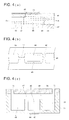
- Fig. 4 (a) is a cross-sectional view of an example of this pump and Fig. 4 (b) is a top view thereof.
- the micro pump comprises: a first fluid chamber 48, a first flow path 46, a pressure chamber 45, a second flow path 47, and a substrate 42 formed by the second fluid chamber 49, an upper substrate 41 which is formed as a layer on the substrate 42, and a vibration plate 43 which is formed as a layer on the upper substrate 41, a pressure chamber 45 of the vibration plate 45, a piezoelectric element 44 which is formed as a layer on the side opposite to the pressure chamber side of the vibration plate 43, and a drive portion (not shown) for driving the piezoelectric element 44.
- a light-sensitive glass substrate having a thickness of 500 ⁇ m is used as the substrate 42, and by performing etching until a depth of 100 ⁇ m is reached, the fluid chamber 48, the first flow path 46, the pressure chamber 45, the second flow path 47, and the second fluid chamber 49 are formed.
- the width of the first flow path 46 is 25 ⁇ m and the length is 20 ⁇ m.
- the width of the second flow path 47 is 25 ⁇ m and the length is 150 ⁇ m.
- the upper surface of the first fluid chamber 48, the first flow path 46, the second fluid chamber 49, and the second flow path 47 are formed by the upper substrate 41 which is a glass substrate being formed as a layer on the substrate 42.
- the portion which contacts the upper surface of the pressure chamber of the upper substrate 41 is processed by etching and the like and thereby penetrated.
- a thin vibration plate formed from thin glass having a thickness of 50 ⁇ m is formed as a layer on the upper surface of the upper substrate 41 and a piezoelectric element 44 formed from lead titanate zirconate (PZT) ceramics of a thickness of 50 ⁇ m, for example, is formed as a layer thereon.
- PZT lead titanate zirconate
- the piezoelectric element 44 and the vibration plate 43 adhered thereto are vibrated by the drive voltage from the driving section, and the capacity of the pressure chamber 45 is thereby increased and decreased.
- the width and depth of the first flow path 46 and the second flow path 47 are the same, and the length of the second flow path is greater than that of the first flow path, and if the pressure difference in the first flow path 46 is large, turbulence such that of whirlwind is generated and the flow path resistance increases.
- the second flow path 47 is a long flow path, even if the pressure difference is large, laminar flow is facilitated and the change ratio of the flow path resistance with respect to the change in the pressure difference is smaller than for the first flow path.
- the vibration plate 43 is quickly displaced in the inner direction of the pressure chamber 45, and the capacity of the pressure chamber is 45 is reduced while a large pressure difference is being applied, and next the vibration plate 43 is slowly displaced to the outer direction from the pressure chamber 45 and the capacity of the pressure chamber 45 is increased while a small pressure difference is being applied and the fluid is fed in direction B in the drawing.
- Fig. 5 shows an example of the relationship between the drive voltage waveform which is applied to the piezoelectric element 44 and the position displacement of the fluid.
- the graph of fluid migration quantity shown in Fig. 5 (b) is a pattern graph of the flow quantity obtained by operation of the pump, and shows behavior when time delay or inert vibrations due to inertial force of the fluid are weighed. It is to be noted that difference in the change ratio of the flow path resistance with respect to the change in pressure difference in the first flow path and second flow path is not necessarily due to the difference in the length of the flow paths and may be based on other configuration differences.
- Fig. 4 (c) shows another example of the pump.
- the pump comprises a silicon substrate 71, a piezoelectric element 44, and a flexible wire that is not shown.
- the silicone substrate 71 is a silicon wafer which has been processed to have a prescribed shape by known photolithography techniques, and the pressure chamber 45, the diaphragm 43, the first flow path 46, the first fluid chamber 48, the second flow path 47 and the second fluid chamber 49 are formed by etching.
- the first fluid chamber 48 has a port 72 while the second fluid chamber 49 has a port 73 and the fluid chambers communicate with the pump connection portion of the microreactor via these ports.
- the pump can be connected to the microreactor by vertically superposing the substrate 74 into which the port is formed and the vicinity of the pump connection portion of the microreactor.
- a plurality of pumps may be formed on a single silicon substrate.
- the port at the opposite side of the port that is connected to the microreactor preferably has a drive fluid tank connected thereto. In the case where there is a plurality of tanks, their ports may be connected in common to the drive fluid tank.
- Fig. 6 (a) shows the structure of the pump portion for feeding the drive fluid
- Fig. 6 (b) shows the structure of the pump portion for feeding the reagent.
- the drive fluid 24 herein may be an oil based substance such as mineral oil or a water based substance and the sealing fluid which seals the reagent may be loaded in the flow path as shown in Fig. 3 or may be loaded in a reservoir section for the sealing fluid.
- the flow path between the pump connection portion 12 and the reagent storage section 18 has an air vent flow path 26. As shown in Fig. 7, the air vent flow path branches from the flow path 15 between the pump connection portion and the reagent storage section and the end thereof is open. When the pump is connected for example, air bubbles present in the flow path 15 are removed through the air vent flow path 26.
- the diameter of the air vent flow path 26 is preferably no greater than 10 ⁇ m in view of preventing leakage of water and other aqueous fluids, for example that pass through the flow path 15 and it is also preferable that the contact angle of the inner surface of the flow path with water is not less than 30°.
- the driving of the micro pumps for feeding these substances is controlled as described in the following.
- Fig. 8 (a) in the case where the reagent is fed in the A direction from upstream of the Y-shaped flow path and the specimen 33 is sent in the B direction, and as a result, they are mixed in the flow path 15, driving of the pump which feeds the reagent 31 and the pump which feeds the specimen 33 are controlled as shown in Fig. 8 (c).
- driving of the pump which feeds the reagent 31 and the pump which feeds the specimen 33 are controlled as shown in Fig. 8 (c).
- the reagent 31 and the specimen 33 are alternately fed into the flow path 15 in a sectional state.
- the width of the section layer may, for example be 1 to 2 ⁇ m. The shorter the width of the layer, the faster the dispersion between the reagent 31 and the specimen 33 and they are thereby mixed.
- a reagent layer and a specimen layer having a width of approximately 50 ⁇ m are formed and when compared to the case of Fig. 8 (a), it is difficult for dispersion to progress and mixing is delayed.
- a plurality of feed control sections are provided in the flow path of the microreactor of this embodiment as shown in Fig. 9 (a).
- the feed control section interrupts the passage of fluid pressure in the normal direction until a prescribed pressure is reached, and passage of the fluid is permitted when a pressure not less than the prescribed pressure is applied.
- the feed control section 13 is formed of a contracted diameter portion of the flow path, and due to this portion, the passage from the other end of fluid reaching the contracted flow path (micro flow path) 51 from one end side is regulated.
- the contracted flow path 51 is formed, for example with a length and width of about 30 ⁇ m x 30 ⁇ m in contrast to flow path with length and width of 150 ⁇ m x 150 ⁇ m and both sides are linearly connected.
- a prescribed feed pressure is required for surface tension. Accordingly, because stopping and flowing of the fluid can be controlled by the pump pressure from the micro pump, migration of the fluid at a prescribed location in the flow path can be temporarily stopped for example, and feeding from this prescribed location to the flow path ahead can be resumed at a prescribed timing.
- a water repelling coating such as a fluorine based coating may be provided at the inner surface of the contracted flow path 51.
- the microreactor of this embodiment includes a plurality of reverse flow prevention sections for preventing reverse flow of the fluid in the flow paths.
- the reverse flow prevention section has a check valve in which the flow path opening is closed by a valve element due to reverse flow pressure, or an active valve in which a valve element is pressed onto the flow path opening portion by a valve element deforming means to close the opening.
- Figs. 10 (a) and (b) are cross-sectional views showing an example of the check valve used in the flow path of the microreactor of this embodiment.
- the check valve in Fig. 10 (a) has a microsphere 67 as a valve element and by opening and closing the opening 68 formed in the substrate 62 due to migration of the microsphere 67, the passage of fluid is permitted or interrupted.
- the microsphere 67 separates from substrate 62 due to the fluid pressure and the opening 68 is opened and thus the flow of fluid is permitted.
- the microsphere 67 sits on the substrate 62 and the opening 68 is closed, and thus the flow of fluid is interrupted.
- the check valve in Fig. 10 (b) is formed as a layer on the substrate 62 and the plastic substrate 69 whose end has play above the opening 68 opens and closes the opening 68 due to upward and downward movement above the opening 68 due to fluid pressure.
- the end of the plastic substrate 69 separates from substrate 62 due to the fluid pressure and the opening 68 is released and thus the flow of fluid is permitted.
- the plastic substrate 69 sits on the substrate 62 and the opening 68 is closed, and thus the flow of fluid is interrupted.
- Fig. 11 is a cross-sectional view of showing an example of the active valve used in the flow path of the microreactor of this embodiment, and Fig. 11 (a) shows the valve in an open state while Fig. 11 (b) shows the valve in closed state.
- the plastic substrate 63 which has a valve portion 64 that protrudes downward is formed as a layer on top of substrate 62 in which the opening 65 is formed.
- valve portion 64 adheres to the substrate 62 so as to cover the opening by pressing a valve deforming means such as an air pressure piston, an oil pressure piston or a water pressure piston or a piezoelectric actuator, or a shape memory alloy actuator, and reverse flow in the B direction is thereby prevented.
- a valve deforming means such as an air pressure piston, an oil pressure piston or a water pressure piston or a piezoelectric actuator, or a shape memory alloy actuator
- the operation of the active valve is not limited to an external driving device, and the valve itself may deform to close the flow path.
- the bimetal 81 may be used and deformation may be done by electrical heating, or alternatively, as shown in Fig. 19, deformation may be done by heating using a shape memory alloy 82.
- Fig. 12 shows the structure of this type reagent assay section, and the feed path (reagent loading flow path 15a) between the reverse flow portion 16 and the feed control section 13a is loaded with a prescribed quantity of reagent.
- the reagent loading flow path 15a is provided with a branched flow 15a path which branches therefrom and communicates with the micro pump 11 which feeds the drive fluid.
- Feeding of fixed quantities of the reagent is performed as follows. First, the reagent 31 is loaded by being supplied to the reagent loading flow path 15a using a feed pressure that does not allow the reagent 31 to pass forward from the feed control portion 13a from the reverse flow portion 16 side. Next, by feeding the drive fluid 25 in the direction of the reagent loading flow path 15a from the branched flow path 15b using the micro pump 11 with the feed pressure that allows the reagent 31 to pass forward from the feed control portion 13a, the reagent 31 that has been loaded in the reagent loading flow path 15a is pushed forward from the reagent loading flow path 15a, and as a result a fixed quantity of the reagent 31 is fed.
- the branched flow path 15b sometimes has air or sealing fluid present therein, but even in this case, the drive fluid 25 is fed by the micro pump 11, and the air, the sealing fluid and the like are sent into the reagent loading flow path 15a to thereby push out the reagent. It is to be noted that by providing a large capacity reservoir section 17a in the reagent loading flow path 15a, variation in the fixed volume is reduced.
- Fig. 13 shows the flow path structure in which the front portion is discarded and the mixture is fed to the next step after the mixing ratio has been stabilized.
- the reagents 31a and 31b which are mixed are fed from the flow paths 15a and 15b respectively to the mixing flow paths 15c.
- the branched path 15d which feeds the reagent mixture 31c from the mixing flow path 15c to the next step is branched, and a first feed control section 13a is provided at a position beyond the branching point of the branched flow path 15d in the mixing flow path 15c.
- a second feed control section 13b is provided at a position in the vicinity of the branching point of the mixing flow path 15c in the branched flow path 15d and the feed pressure which allows the reagent mixture 31c to pass is smaller than that of the first feed control section 13a.
- the reagent mixture 31c of reagent 31a and reagent 31b which were fed from the flow path 15a and the flow path 15b to the mixing path 15c is fed into the mixing path 15c until the front end portion 31d of the reagent mixture 31c reaches the first feed control section 31a. After the front end portion 31d of the reagent mixture 31c reaches the first feed control section 31a, by further feeding into 15c, the reagent mixture 31c is passed from the second feed control section 13b to the branched flow path 15d, and then the reagent mixture 31c is fed to the next step.
- the feeding pressure which allows passage of the reagent mixture 31c in the second feed control section 13b can be made smaller than that of the first feed control section 13a.
- a reagent including a biotin modified chimera primer for specific hybridization of the gene to be detected, a DNA polymerase having strand activity, and an endonuclease are stored in the reagent storage sections 18a, 18b and 18c in Fig. 14 and a piezo pumps 11 which are built into the main body device which is separate from the microreactor are connected at the upstream side of each of the reagent storage portions using the pump connection portion 12, and reagent is fed from each of the reagent storage sections to path 15a at the downstream side, by these pumps.
- the flow path 15a, the flow paths to the next step which are branched from flow path 15a, and the feed control sections 13a and 13b form the flow path illustrated in Fig. 13, and the front portion of the mixture of reagents fed from the reagent storage section is discarded and the mixture is fed to the next step after the mixing ratio has been stabilized.
- a total of over 7.5 ⁇ l of reagent is stored in each of the reagent storage sections and of the total of 7.5 ⁇ l of reagent mixture, 2.5 ⁇ l each of the discarded front end portion is sent to the 3 branched flow paths 15b, 15c and 15d.
- the flow path 15b communicates with reaction and detection system for the specimen (Fig. 15)
- the flow path 15c communicates with reaction and detection system for the positive control (Fig. 16)
- the flow path 15d communicates with reaction and detection system for the negative control (Fig. 17).
- reagent loading path illustrated in Fig. 12 is formed between the check valve 16 at the upstream side of the reservoir section 17 and the feed control section 13a at the downstream side, and it forms the above-described reagent assay section along with the feed control section 13b provided in the branched flow path which communicates with the pump 11 which feeds drive fluid.
- a specimen extracted from blood or sputum is poured from the specimen storage section 20 and the specimen is loaded in the reservoir section 17 in a fixed quantity (2.5 ⁇ l) using the same structure as the reagent assay section, and fed in a fixed quantity to connected flow path.
- the specimen and reagent mixture that are loaded in the reservoir sections 17 are fed to the Y-shaped flow path via the flow path 15e (volume 5 ⁇ l) and mixing and ICAN reaction are performed in the flow path 15e.
- the feeding of the specimen and the reagent is done by alternately driving each of the pumps 11 and alternately introducing specimen and reagent mixture in sections to the flow path 15e and the specimen and the reagents are quickly dispersed and mixed.
- the amplification reaction is stopped by feeding 5 ⁇ l of reaction solution and 1 ⁇ l of reaction stopping solution stored in the stopping solution storage section 21a into the flow path 15f which has a capacity of 6 ⁇ l and mixing them.
- the denaturant (1 ⁇ l) stored in the denaturant storage section 21b and a mixture (0.5 ⁇ l) of the reaction solution and the stopping solution are fed to the flow path 15g having a capacity of 1.5 ⁇ l and mixed and one strand of the amplified gene is denatured.
- the 2 ⁇ l of processing solution is fed to each of the streptavidin adsorbing sections 22a and 22b in which streptavidin has been adsorbed in the flow path, and the amplified gene that has been marked with the probe is fixed in the flow path.
- the rinsing solution, the internal control probe DNA solution, and the gold colloid solution marked with the FITC antibody stored in each of the storage sections 21d, 21f, and 21e are fed in the order shown in the figure, inside the flow path 22a in which the amplified gene is fixed, by a single pump 11.
- the rinsing solution, the MTB probe DNA solution and the gold colloid solution marked with the FITC antibody stored in each of the storage sections 21d, 21g, and 21e are fed in the order shown in the figure, inside the flow path 22b in which the amplified gene is fixed, by a single pump 11.
- the gold colloid is bound to the fixed amplified gene via the FITC by feeding the gold colloid solution and is thereby fixed.
- optically detecting the fixed gold colloid a determination is made as to whether there was amplification or the efficiency of amplification is measured.
- the flow paths 15c and 15d in Fig. 14 communicate with the positive control reaction and detection system shown in Fig. 16 and the negative control reaction and detection system shown in Fig. 17 respectively and by feeding the reagent mixtures thereto, as in the case of the above-described specimen reaction and detection system, after the amplification reaction is performed with the reagent in the flow path, hybridization is performed with the probe DNA stored in the probe DNA storage section in the flow path, and amplification reaction detection is done based on reaction products.
Abstract
Description
- This invention relates to a microreactor and particularly to a gene testing device including a bioreactor which can be favorably used for gene testing.
- In recent years, due to the demands of micro-machine technology and microscopic processing technology, systems are being developed in which devices and means (for example pumps, valves, flow paths, sensors and the like) for performing conventional sample preparation, chemical analysis, chemical synthesis and the like are caused to be ultra-fine and integrated on a single chip. This is also called µ-TAS (Micro Total Analysis System) bioreactor, lab-on-chips, and biochips, and much is expected of their application in the fields of medical testing and diagnosis, environmental measurement and agricultural manufacturing. As seen in gene testing in particular, in the case where complicated steps, skilful operations, and machinery operations are necessary, a microanalysis system which is automatic, has high speed and simple is very beneficial not only in terms of cost, required amount of sample and required time, but also in terms of the fact that it makes analysis possible in cases where time and place cannot be selected.
- For example, for the new contagious diseases seen in humans and animals, identifying the virus or bacteria which cause these diseases is the first barrier to finding preventative measures within a very limited time. While conventional detection methods tend to be limited by the cultivation of bacteria, gene testing technology which quickly produces results in the case where location is predetermined, responds to the urgent demands. Furthermore, there is a great need for gene testing in diagnosis of genetic diseases, illness risk measurement for lifestyle diseases, and in genetic medicine.
- In clinical testing, the quantitative properties of the analysis, accuracy of the analysis and economic factors with respect to the analyzing chip in the clinical examination will be of great importance. As a result, the task at hand is to ensure a feeding system which has a simple structure and is highly reliable. A micro fluid control element which has high accuracy and excellent reliability is desired. The inventors of this invention have already proposed a micro pump system which is suitable for this (
Patent Documents 1 and 2). - In addition, chips which are designed to be disposable are desired for use for large numbers of clinical samples, and in addition, problems of multipurpose application and manufacturing cost must also be surmounted.
- In a DNA chip in which many DNA fragments are fixed with high accuracy, there are problems relating to information content, increasing production cost, detection accuracy and insufficient replication. However, depending on the purpose and type of genetic screening, tracking the efficiency of the DNA amplification reaction using a primer which can change suitably in real time is more likely to provide a simple and quick testing method than the system in which multiple DNA probes are disposed over the entire chip substrate.
-
Japanese Patent Application Laid-Open No. 2001-322099 -
Japanese Patent Application Laid-Open No. 2004-108285 - "DNA Chip Technology and Applications" "Proteins, Nucleic Acids and Enzymes"
- An object of the present invention is to provide a microreactor which is low cost and designed to be disposable and has a feeding system having a simple structure with high accuracy so as to make highly accurate detection possible, in particular, to provide a microreactor for testing gene. An object of this invention is also to provide a bio-microreactor having a structure which makes occurrence of problems such as cross-contamination and carry-over contamination unlikely.
- The gene testing device of this invention was conceived in view of the above-described situation and performs the type of DNA amplification in which the primer and bioprobe used can change appropriately in order to ensure multipurpose use and high speed.
- The above object can be achieved by the following structures.
- A micro-reactor for analyzing a sample, comprising:
- (1) a plate-shaped chip;
- (2) a plurality of reagent storage sections each having a chamber to store respective agents;
- (3) a reagent mixing section to mix plural reagents fed from the plurality of reagent storage sections so as to produce a mixed reagent;
- (4) a sample receiving section having an injection port through which a sample is injected from outside; and
- (5) a reacting section to mix and react the mixed reagent fed from the reagent mixing section and the sample fed from the sample receiving section;
- In the above micro-reactor, the reagent mixing section comprises a mixing flow path and a feed-out flow path to feed out the mixed reagent to the reacting section, and wherein the feed-out flow path is branched from a middle point of the mixing flow path so that the initially-mixed reagent is accommodated in a portion of the mixing flow path between the middle point and a downstream end of the mixing flow path.
- In the above micro-reactor, the reagent mixing section further comprises a feed-out control section provided at the middle point of the mixing flow path so as to connect the mixing flow path and the feed-out flow path, and wherein the feed-out control section allows the mixed reagent to pass from the mixing flow path to the feed-out flow path when an inner pressure in the mixing flow path becomes higher than a predetermined pressure.
- A micro-reactor for analyzing a sample, comprising:
- (1) a plate-shaped chip;
- (2) a plurality of reagent storage sections each having a chamber to store respective agents;
- (3) a reagent mixing section to mix plural reagents fed from the plurality of reagent storage sections so as to produce a mixed reagent;
- (4) a sample receiving section having an injection port through which a sample is injected from outside; and
- (5) a reacting section to mix and react the mixed reagent fed from the reagent mixing section and the sample fed from the sample receiving section;
-
- Fig. 1 is a schematic view of the gene testing microreactor of an embodiment of this invention.
- Fig. 2 is a schematic view of the gene testing device comprising the microreactor and the device main body of Fig. 1.
- Fig. 3 shows the state in which sealing agent is loaded between the reagent storage section and the flow path communicating therewith.
- Fig. 4 shows a piezo pump and Fig. 4 (a) is a cross-sectional view of an example of this pump while Fig. 4 (b) is a top view thereof. Fig. 4 (c) is cross-sectional view of another example of the piezo pump.
- Fig. 5 is a graph showing the relationship between the drive voltage waveform which is applied to the piezo electric element in the pump and the position displacement of the fluid position.
- Fig. 6 (a) shows the structure of the pump portion for feeding the drive fluid and Fig. 6 (b) shows the structure of the pump portion for feeding the reagent.
- Fig. 7 shows the air vent flow path.
- Figs. 8 (a) and (b) show the mixture of the specimen and the reagent in the flow path by being fed from above the Y-shaped flow path and Fig. 8 (c) is graph showing the driving of the feed pump.
- Figs. 9 (a) and (b) are cross-sectional views in the flow path axial direction of the
feed control section 13. - Fig. 10 (a) and (b) are cross-sectional views showing an example of the check valve provided in the flow path.
- Fig. 11 is a cross-sectional view showing an example of the active valve provided in the flow path and Fig. 11 (a) shows the open state while Fig. 11 (b) shows the closed state.
- Fig. 12 shows the structure of this type reagent assay section.
- Fig. 13 shows the flow path structure in which the front portion is discarded and the mixture is fed to the next step after the mixing ratio has been stabilized.
- Fig. 14 shows the structure of the reagent mixing portion of the microreactor in an embodiment of this invention.
- Fig. 15 shows the structure of the portion which communicates with the flow paths in Fig. 14 and performs the amplification reaction of the specimen and the reagents and detection thereof.
- Fig. 16 shows the structure of the portion which communicates with the flow paths in Fig. 14 and performs the amplification reaction of the positive control and the reagents and detection thereof.
- Fig. 17 shows the structure of the portion which communicates with the flow paths in Fig. 14 and performs the amplification reaction of the negative control and the reagents and detection thereof.
- Fig. 18 is a cross-sectional view of an example active valve provided in the flow path, and Fig. 18 (a) shows an open state of the valve while Fig. 18 (b) shows a closed state.
- Fig. 19 is a cross-sectional view of an example active valve provided in the flow path, and Fig. 19 (a) shows an open state of the valve while Fig. 19 (b) shows a closed state.
- Firstly, the above object may be achieved by the following preferable structures.
- The gene testing microreactor of this invention comprises on a single chip:
- a specimen storage section into which a specimen or DNA extracted from a sample is poured;
- a reagent storage section into which the reagent used in the gene amplification reaction is stored;
- a positive control storage section into which the positive control is stored;
- a negative control storage section into which the negative control is stored;
- a probe DNA storage section into which the probe DNA for hybridization with the gene for detection that has been amplified by a gene amplification reaction is stored;
- a flow path for causing the storage sections to communicate; and
- a pump connection portion which can connect with each of the storage sections and with a separate micro-pump which feeds fluid in the fluid flow path, and
- after the micro pump is connected to chip via the connection portion, and the specimen or the DNA extracted from the specimen stored in the specimen storage section and the reagent stored in the reagent storing section are fed to the flow path and then mixed in the flow path to cause an amplification reaction, the processing fluid resulting from processing the reaction fluid and the probe DNA stored in the probe DNA storage section are fed, and mixed and hybridized in the flow path, and the amplification reaction detection is performed based on the reaction products, and similarly, the positive control stored in the positive control storage section and the negative control stored in the negative control storage section undergo amplification reaction with the reagent stored in the reagent storage section in the flow path, and then hybridization with the probe DNA stored in the probe DNA storage section in the flow path and amplification reaction detection is performed based on the reaction products.
- The gene testing microreactor comprises a reverse transcription enzyme storage section into which the specimen or RNA extracted from the specimen stored in the specimen storage section is poured, and which stores the reverse transcription enzyme for synthesizing cDNA from the RNA stored therein using a reverse transcription reaction, and
the specimen or the RNA extracted from the specimen stored in the specimen storage section and the reverse transcription enzyme stored in the reverse transcription storage section are fed to the flow path and mixed in the flow path and cDNA is synthesized and then the amplification reaction and the detection thereof is performed. - Also, in the gene testing microreactor, the flow path comprises:
- a feed control section which is capable of controlling the passage of fluid by the pump pressure of the micro pump by interrupting the passage of fluid until the feed pressure in the normal direction of flow reaches a preset pressure, and permitting passage of the fluid by applying a feed pressure which is no less than the preset pressure and
- a reverse flow prevention section for preventing reverse flow of the fluid in the flow path, and
- the micro pump controls the feed, quantity, and mixing of each of the fluids in the flow path using the feed control section and the reverse flow prevention section.
- In addition, the gene testing microreactor comprises a micro flow path which is formed between both sides of adjacent flow paths so as to connect in a straight line and which have a cross-sectional area which is smaller than the cross-sectional area of the adjacent flow paths.
- In the gene testing microreactor, the reverse flow prevention section is a check valve in which a valve element closes the opening of the flow path using reverse flow pressure or an active valve in which a valve element is pressed onto the flow path opening portion by a valve element deforming means to close the opening.
- The gene testing microreactor comprising a reagent loading flow path which is formed between the reverse flow prevention section and the feed control section, and is capable of loading a prescribed quantity of reagent; and
a branched flow path which branches from the reagent loading flow path and communicates with the micro pump which feeds drive fluid and the connected pump connection portion;
and after reagent is loaded by supply of the reagent from the reverse flow prevention section side to the reagent loading flow path by the feed pressure due to the reagent not passing from the from the fluid feed control section forward. - Furthermore, the gene testing microreactor comprises:
- a plurality of flow paths for feeding the reagents;
- a mixing flow path which is connected to the plurality of flow paths and in which the reagents from these flow paths are mixed;
- a branched flow path which branches from the mixed flow path and which feeds the reagent mixture to the next step;
- a first feed control section which is disposed at a position beyond the branching point of the branched flow path in the mixing flow path;
- a second feed control section which is disposed at a position in the vicinity of the branching point of the mixing flow path in the branched flow path and the feeding pressure which allows the reagent mixture to pass is smaller than that of the first feed control section,
- and after the reagent mixture is fed until the front end portion of the reagent mixture which is fed in the mixing flow path reaches the first feed control section, the reagent mixture is passed from the second feed control section to the branched flow path at a feed pressure that does not allow the reagent mixture to pass the first feed control section, and then the reagent mixture is fed to the next step.
- In the gene testing microreactor, the cross-sectional area of the micro flow paths in the first feed control section is smaller than the cross-sectional area of the micro flow paths in the second feed control section.
- In the gene testing microreactor, an air vent path which branches from the flow paths and has an open end is provided in the flow path between the pump connection portion and the storage section in which the content fed by the micro pump connected to the pump connection portion is stored.
- In the gene testing microreactor, the reagent used for the gene amplification reaction, the positive control and the negative control are preferably stored in the storage section.
- In the gene testing microreactor, the space between the storage section which store the reagent used for the gene amplification reaction, the positive control and the negative control and the flow path communicating therewith is loaded with a sealing agent for preventing leakage of the content of the storage section to the flow path before use.
- The sealing agent is preferably formed of a fat which has a solubility in water of not more than 1%.
- It is desirable that the sealing agent is formed of a fat which has a solubility in water of not more than 1%, and a melting point of 8°C to room temperature (25°C).
- The sealing agent is preferably an aqueous solution of gelatin.
- In the gene testing microreactor, the reagent used in the gene amplification reaction includes a chimera primer which hybridizes specifically with the gene to be detected, a DNA polymerase having chain substitution activity, and an endonuclease.
- A gene testing method of this invention comprises:
- a step of feeding the cDNA synthesized by a reverse transcription reaction by the specimen or the DNA extracted from the specimen, or alternatively the specimen or the RNA extracted from the specimen and a biotin modified primer from the respective storage section to the flow path and performing a gene amplification reaction in a flow path;
- a step of mixing the reaction solution including the amplified gene and the denaturant and denaturing the amplified gene into a single strand;
- a step of feeding the processing solution that has undergone processing for denaturing the amplified DNA to a single strand into a flow path to which streptavidin has been adsorbed and then and fixing the amplified gene;
- a step of feeding probe DNA whose end has been modified by FITC into the flow path into which the amplified gene is fixed and hybridizing the fixed gene with the probe DNA;
- a step of feeding gold colloid whose surface has been modified with a FITC antibody into the flow path and adsorbing gold colloid into the probe which has been hybridized with the fixed gene;
- and a step of optically measuring the concentration of the gold colloid in the flow path, using any of the microreactors described above.
- It is preferable that a step of feeding rinsing solution in the flow path in which streptavidin is adsorbed is included if necessary between each of the steps.
- The gene testing device of this invention comprises one of the microreactors and a micro pump for connection to the pump connection portion of the microreactor.
- The gene testing device comprises:
- a first flow path in which the micro pump changes the flow path resistance in accordance with pressure difference;
- a second flow path in which the change ratio for the flow path resistance with respect to the change in pressure difference is less than that for the first flow path;
- a pressure chamber which is connected to the first flow path and the second flow path;
- an actuator for changing the internal pressure of the pressure chamber; and
- a driving device for driving the actuator.
- In the gene testing device, a pump connection portion is provided at the upstream side of each reagent storage section in which the reagent is stored and a micro pump is connected to the pump connection portions, and reagent is pushed out from the reagent storage section to the flow path by supplying drive fluid from each micro pump to start the gene amplification reaction.
- In the gene testing device, the reagents are mixed at a desired ratio by controlling the operation of the actuator using drive signals from the driving device of the micro pump.
- The gene testing device preferably comprises a detection device for detecting the amplification reaction based on the reaction products of hybridization of the amplified gene and the probe DNA.
- The gene testing preferably comprises a temperature control device for controlling the reaction temperature for each reaction in the flow path of the microreactor.
- The gene testing device comprises a device main body in which the micro pump, the detector device and the temperature control device are integrally formed and a microreactor which can be installed on the device main body, and gene amplification reaction and the gene amplification reaction detection are automatically performed by installing the microreactor on the device main body.
- The microreactor of this invention has a structure which is suitable for large volume production, and furthermore because application is universal for multiple purposes, it can be manufactured at a low cost. In addition, because the flow path system including pumps and valves has a simple structure, it is difficult for air to enter the system and there is little dead volume and thus feeding accuracy is high. Because a DNA amplification step is included at the time of detection, the bioreactor is capable of high accuracy detection.
- Because the analysis reactor can realize reverse transcription not only for DNA analysis, but also for RNA, sample preparation is easy and even an extremely small quantity can be analyzed with high accuracy in a short time.
- In addition, because the system structure of the gene testing device of this invention is such that the reagents/feeding system element loading component and the control/detection component for each sample are separate, occurrence of serious problems such as cross contamination and carry over contamination is unlikely for the small quantity analysis and the amplification reaction. Because the rinsing method for non-specific binding substances other than primer and probe binding with the sample DNA (or interaction) is easy, a microreactor chip with a low background can be provided.
- This invention may be used in gene expression analysis, gene function analysis, single nucleotide polymorphism analysis (SNP), medical screening, medicine, testing of the safety/toxicity of agricultural chemicals and various chemical substances, clinical diagnosis in medicine, food inspection, forensic medicine, chemistry, brewing, forestry, fishery, stock breeding, agricultural manufacturing and the like.
- The following is a description of the microreactor of this invention; the gene testing device comprising the microreactor, various control devices and a detection device; and the gene testing method including the gene amplifications steps and detection steps.
- Microreactor and Gene testing Device
- The microreactor and gene testing device of this invention will be described with reference to the drawings. Fig. 1 is a schematic view of the microreactor for the gene testing device of an embodiment of this invention and Fig. 2 is a schematic view of the gene testing device comprising the microreactor and the device main body of an embodiment of this invention.
- The microreactor shown in Fig. 1 comprises a single chip made of resin, glass, silicon, ceramics and the like. The chip comprises specimen storage sections, reagent storage sections, probe DNA storage sections, control storage sections, flow paths, pump connection sections, feed control sections, reverse flow prevention sections, reagent assay section, and each of the mixing sections is disposed at a functionally suitable position using micro-processing technology. Furthermore, if necessary, a reverse transcription enzyme section may be installed. The specimen storage section communicates with the specimen introduction section and temporarily stores the specimen and supplies the specimen to the mixing section. In some cases, the specimen storage section may have the effect of blood cell separation. Mixture of reagent and reagent, and mixture of specimen and reagent can be done in a single mixing section at a prescribed ratio or alternatively, one or both may be divided and a plurality of converging sections provided and mixing is done so as to achieve a final desired mixing ratio.
- By introducing a specimen such as blood or the like into the specimen storage section of the microreactor, the processes necessary for gene amplification and detection thereof are automatically performed in the chip, and gene testing can be done simultaneously for multiple items in a short period of time. In the aspect of the preferable gene testing device used in the microreactor of this invention, the necessary reagents are sealed in advance in a prescribed quantity, and the microreactor is used as a unit for performing a prescribed amplification and detection of the amplification products for the DNA or RNA of each specimen.
- Meanwhile, the unit which handles the control system for controlling the feeding, temperatures and reactions, optical detection, data collection and processing comprises micro pumps, optical devices and the main body of the gene testing device of this invention. Installing the above-described chip on the device main body allows shared use for the specimen sample. Thus, processing can be done efficiently and quickly even for multiple samples. In the prior art technology when analysis for different content or synthesis and the like is performed, a micro fluid device corresponding to the content to be changed needed to be configured each time. Unlike that case, in this invention it is sufficient to simply replace the detachable chip. Also if it is necessary to change control of the device elements, the control program stored in the device main body can simply be altered.
- Because each of the components of the gene testing device of this invention has a form that is compact and convenient for handling, the components are not limited in terms of location and time of use and thus workability and operation properties are favorable.
- The outline of the microreactor and the screening device of this invention was described above, but suitably selected modifications and variations of the various embodiments of this invention which are within the general principles of this invention is possible and these are included in this invention. In other words, structure, configuration, arrangement, shape, dimensions, material system, method and the like of a portion or of the entire microreactor and screening device of this invention may vary provided that they are consistent with the general principles of the invention.
- The specimen of this invention to be determined is a gene, DNA or RNA as the nucleic acid which is the matrix for the amplification reaction in the case of gene testing. The sample may also be one prepared or isolated from a sample which may include this type of nucleic acid. The method for preparing genes, DNA or RNA from this sample is not particularly limited and known techniques may be used. In recent years, techniques for preparing genes, DNA or RNA from a living sample for gene amplification have been developed and these may be used in the form of a kit or the like.
- The sample itself is not particularly limited and includes almost all samples of biological origin such as whole blood, serum, Buffy coat, urine, feces, saliva and sputum; samples including nucleic acid such as cell cultures, viruses, bacteria, mold, yeast, plants and animals; samples that may include, or into which microorganism are blended; and various other samples that may include other nucleic acids.
- The DNA can be separated from the sample and purified in accordance with a usual method by phenol chloroform extraction and ethanol sedimentation. Use of a high concentration chaotropic sample such as guanidine hydrochloride and isothiocyanic chloride which is near saturation concentration for isolating nucleic acid is generally known. A method, in which the specimen is directly processed with a protein decomposition enzyme solution including a surfactant (PCR Experiment Manual by Takashi Saito, published by HBJ publishers 1991, P309), rather than using the phenol chloroform extraction described above, is simple and quick. In the case where the genome DNA or the gene obtained is large, a suitable control enzyme such as BamHI, BgLII, DraI, EcoRI, EcoRV, HindIII, PvuII and the like and performing fragmentation according to a conventional method. In this manner, DNA and aggregates of fragments thereof can be prepared.
- The RNA is not particularly limited provided that the primer used in the transcription reaction can be produced. Aside from whole RNA, RNA molecule groups such as retroviral RNA which functions as a gene, mRNA or rRNA which are direct information transmission carriers for the expressed gene can be screened. These RNAs may be converted to cDNA using a suitable reverse transcription enzyme and then analyzed. The method for preparing mRNA can be done based on known technology and reverse transcription enzymes are readily available.
- The quantity of sample required in the microreactor of this invention is much less than that for the operation using the device of the prior art. For example, in the case of a gene, the quantity of DNA required is 0.001 to 100 ng. As a result, there are no limitations in terms of the sample for use of the microreactor of this invention including case where only an extremely small quantity of sample can be obtained, and when the quantity is inevitably small because of the nature of the sample, and thus screening cost is reduced. The sample is introduced from the introduction section of the "specimen storage section" described above.
- The amplification method in the microreactor of this invention is not particularly limited. For example the DNA amplification method may be the PCR amplification method which is used extensively in a wide range of applications. The various conditions for implementing the amplification technology have been studied in detail, and are described along with modifications in various documents. In PCR amplification, temperature control in which temperature is increased and decreased between 3 temperatures is necessary, but a flow path device which is capable of favorable control of the microchip has already been proposed by the inventors of this invention (
Japanese Patent Application Laid-Open 2004-108285 - In the recently developed ICAN (isothermal chimera primer initiated nucleic acid amplification) in which the complicated temperature controls of PCR reaction is unnecessary, the DNA amplification can be carried out is a short time at a suitably selected fixed temperature which is 50°C to 65°C (
Japanese Patent No. 3433929 - The DNA amplification reaction may be other modified PCR methods, and the microreactor of this invention has the flexibility of handling these methods by changing the flow path settings. In the case where any of the DNA amplification reactions is used also, details of the techniques are disclosed and can be easily introduced by one skilled in the art.
- The PCR primer is 2 types of complementary oligonucleotide on both ends of the DNA strand with a specific site for amplification. The settings have already been developed by dedicated applications and one skilled in the art can easily make the primer using a DNA synthesizer or a chemical synthesizer. The primers for the ICAN method are the DNA and RNA chimera primer and the preparation method for these substances have already been technologically established (
Japanese Patent No. 3433929 - In addition, if biotin is bound with the primer, the amplified DNA product can be fixed on a substrate via binding of streptavidin with the substrate and a fixed quantity of the amplification product can be supplied. Other examples of primer marker substances include digoxigenin and various fluorescent dyes.
- The enzymes which are the reagents primarily used in the amplification reaction can be readily obtained by any of the PCR or ICAN methods.
- Examples of the reagent in the PCR method include at least 2-deoxynucleotide 5'-triphosphate as well as Taq DNA polymerase, Vent DNA polymerase or Pfu DNA polymerase.
- The reagents in the ICAN method include at least 2'-deoxynucleotide 5'-triphosphate, a chimera primer that can be hybridized specifically with the gene to be detected, a DNA polymerase having chain substitution activity, and the endonuclease RNase.
- Internal control for the marker nucleic acids (DNA, RNA) is used for amplification monitoring or as an internal standard substance when the quantity is fixed. The sequence of the internal control is such that the primer which is the same as the primer for the specimen can be amplified in the same way as the specimen in order to have a sequence that can be hybridized at both sides of the sequence which is different from the specimen. The sequence of the positive control is a specific sequence which detects the specimen and is the same as that of the specimen in the portion which the primer will hybridize. The nucleic acid used in the control (DNA and RNA) may be any described in a known documents. The negative control includes all reagents other than nucleic acids (DNA, RNA) and are used to check whether there is contamination and for background correction.
- In the case of RNA, the reagent for reverse transcription is a reverse transcription enzyme or a reverse transcription primer for synthesizing cDNA from RNA and these are commercially available and easily obtained.
- A prescribed quantity of the bases for amplification (2'-deoxynucleotide 5'-triphosphate) and the gene amplification reagent and the like respectively are sealed beforehand in the reagent storage section of one microreactor. Accordingly, when the microreactor of this invention is to be used, it is not necessary to supply the necessary quantity if reagent each time, and thus the device is ready for immediate use.
- The DNA detection method for the target gene that has been amplified in this invention is not particularly limited and any suitable method may be used as necessary. A visible light spectrophotometry method, a fluorophotometry method, an emitted luminescence method are considered mainstream as the suitable methods. Further examples include an electrochemical method, surface plasmon resonance, and quartz oscillator microbalance and the like.
- The gene testing device of this invention includes the microreactor as well as a detection device for detecting whether there is an amplification reaction and the scale of the reaction based on the reaction products due to hybridization of the amplified gene and the probe DNA.
- The method of this invention used in the microreactor is more specifically, performed by the following steps. In other words, the method of this invention is performed using the microreactor and includes (1) a step of feeding the cDNA synthesized by a reverse transcription reaction by the specimen or the DNA extracted from the specimen, or alternatively the specimen or the RNA extracted from the specimen and a biotin modified primer from the respective storage section to the flow path and performing a gene amplification reaction in a flow path; (2) a step of mixing the reaction solution including the amplified gene and the denaturant in the micro tubes and performing processing for denaturing the amplified gene into a single strand; (3) a step of feeding the processing solution that has been processed for denaturing the amplified DNA to a single strand to a flow path to which streptavidin has been adsorbed and then and fixing the amplified gene; (4) a step of flowing probe DNA whose end has undergone fluorescent marking with FITC (fluorescein isothiocyanate) into the micro flow path into which the amplified gene is fixed and hybridizing the fixed gene with the probe DNA; (5) a step of flowing gold colloid whose surface has been modified with a FITC antibody which binds specifically with FITC into the micro flow path and adsorbing gold colloid to the probe; and (6) a step of optically measuring the concentration of the gold colloid in the micro flow path.
- In the method described above, fixing by biotin DNA and biotin-streptavidin binding and the FITC fluorescent marking and the like, and the FITC antibody and the like are known technology.
- It is preferable that a step of feeding rinsing solution into the flow path in which streptavidin is adsorbed is included if necessary between each of the steps. Preferable examples of this rinsing solution include various buffer solutions, saline solutions, organic solvents.
- Ultimately, the screening method of this invention is preferably a system which can perform determinations with high sensitivity using visible light. Due to the fluorophotometry, the device is a general use device and hindrances are few and data processing is also easy. Preferably, the optical detection device for fluorophotometry performs detection using the gene testing device of this invention and comprises a feeding means which includes a micro pump and a temperature control device for controlling the reaction temperature for each reaction in the flow paths in the microreactor which are integrally formed.
- In the above step, the denaturant is a reagent for forming the genetic DNA into a single strand, and examples include sodium hydroxide, calcium hydroxide and the like. Examples of the probe include oligonucleotides and the like. Aside from FITC, fluorescent substances such as RITC (rodamine isothiocyanate) and the like may be used.
- The amplification and detection include software with set conditions for the preset feeding procedure, volume and timing as well as micro pump and temperature control as its program content, and when the detachable microreactor is attached to device main body of the gene testing device in which the micro pump, the detection device and the temperature control device are integrated, the flow path of the reactor switches to the operating state. It is preferable that automatic analysis begins when the sample is poured in, and feeding of the sample and reagents, the gene amplification reaction based on the mixing, the gene detection reaction, and optical measurement are automatically performed as a series of continuous steps, and the measurement data as well as required conditions and recording items are stored in a file.
- By using a primer having a specific sequence in a specific gene as the primer for the amplification reaction, a determination as to whether the DNA originating from the genes in the sample is the same or different from the specific gene can be used by determining whether there is amplification and measuring amplification efficiency. In particular, this is effective for quickly identifying viruses and bacteria causing infectious disease.
- Data which examines the level of expression of the cancer gene and the genetic hypertension gene and the like can be obtained using the gene testing of this invention. More specifically, it is an analysis of the type and expression level of the mRNA which is evidence of expression of these genes.
- Alternatively, in addition, susceptibility to infection due to specific diseases, gene variation causing side-effects for medicines, coding regions and the like, and variations in regulator gene promoter regions also can be detected by gene testing using the microreactor of this invention. In that case, a primer that has the nucleic acid sequence including the varied portion is used. It is to be noted that gene variation refers to variation of the nucleotide bases of the gene. Furthermore, by using the gene testing device of this invention, analysis of genetic polymorphism is useful in identifying genes for disease susceptibility.
- It is clear from the device structure and the analytical principles that the gene testing method used in the gene testing device of this invention obtains more accurate results using a much smaller quantity of specimen and is much less labor-intensive and is a simpler device than the nucleic acid sequence analysis, control enzyme analysis, and nucleic acid hybridization analysis of the prior art.
- The microreactor for gene testing and the gene testing device and the like of the present invention may be used in gene expression analysis, gene function analysis, single nucleotide polymorphism analysis (SNP), clinical screening/diagnosis, medical screening, medicine, testing of the safety/toxicity of agricultural chemicals and various chemical substances, environmental analysis, food inspection, forensic medicine, chemistry, brewing, fishery, stock breeding, agricultural manufacturing, forestry and the like.
- The embodiments of this invention will be described in the following with reference to the drawings. Fig. 1 is a schematic view of the microreactor for gene testing of an embodiment of this invention and Fig. 2 is a schematic view of the gene testing device comprising the microreactor and the device main body.
- The microreactor shown in Fig. 1 is formed of a single chip made of resin and by introducing a specimen such as blood or the like therein, the gene amplification reaction and detection thereof are automatically performed in the chip, and gene diagnosis can be done simultaneously for multiple items. For example, by simply dropping about 2 to 3 µl of blood specimen in a chip having length and width of a few cm and by installing the chip on the device
main body 2 of Fig. 2, the amplification reaction and detection thereof can be done. - The specimen that has been poured into the
specimen storage section 20 of Fig. 1 and reagent for the gene amplification reaction which has been sealed beforehand in thereagent storage sections 18a to 18c are fed to the flow paths which communicate with each of the storage sections by the micro pumps (not shown), which are incorporated into the device main body of Fig. 2, and the specimen and the reagents are mixed in the flow path via the Y-shaped flow path and the amplification reaction is performed. The flow path is formed so as to have a width of about 100µm and a depth of about 100 µm, and the detection reaction is detected by the optical detection device (not shown) which is incorporated in the devicemain body 2 of Fig. 2. For example, a measuring beam is irradiated from a LED into the flow path for each item to be detected, and due to detection by transmitted light or reflected light from an optical detection means such as a photodiode or a photomultiplier, the probe DNA is hybridized and as a result the marked DNA (gene) is detected. - The
main body device 2 has a temperature control device for controlling reaction temperature incorporated therein, and by simply installing the chip into which reagents have been sealed in advance onto the compact unit into which the feeding pump, the optical detection device and the temperature control device are integrally formed, gene diagnosis can be done simply. In this manner, because determination can be done quickly without concern for time and place, use for emergency treatment or for personal use such as home treatment is possible. Because multiple micro pump units used for feeding and the like are incorporated at the device main body side, the chip is disposable. - The following is a more specific description of the configuration of the microreactor based on the microreactor of the embodiment of this invention shown in Figs. 14 to 17. The microreactor of this embodiment preferably performs the amplification reaction using the ICAN method, and the gene amplification reaction is performed in the microreactor using a specimen extracted from blood or sputum, a reagent including a biotin modified chimera primer for specific hybridization of the gene to be detected, a DNA polymerase having strand activity, and an endonuclease. The reaction fluid is fed into a flow path into which streptavidin that has been modified is adsorbed and the amplified gene is fixed in the flow path. Next, the probe DNA whose end has been modified by fluorescein isothiocyanate (FITC) and the fixed gene are hybridized and gold colloid whose surface has been modified with a FITC antibody is adsorbed to the probe which has been hybridized with the fixed gene, and the concentration of the gold colloid is optically measured to thereby detect the amplified gene.
- In this embodiment, the microreactor is configured as described in the following so that gene testing can be performed quickly and with high accuracy and high reliability on a single chip. Firstly, all the controls are integrated on a single chip, and the internal control, the positive control and the negative control are sealed beforehand in a microreactor and the amplification reaction and the detection operation for the controls are performed simultaneously with the amplification reaction and the detection operation for the specimen. As a result, gene testing can be performed speedily and is highly reliable.
- Secondly, a feed control section which is capable of controlling the passage of fluid by the pump pressure of the micro pump by interrupting the passage of fluid until the feed pressure in the normal direction of flow reaches a preset pressure, and permitting passage of the fluid by applying a feed pressure which is greater than or equal to the preset pressure and a reverse flow prevention section for preventing reverse flow of the fluid in the flow path is provided at each flow path position. As described below, the feeding of the fluid in the flow path is controlled by the micro pumps, the feed control section and the reverse flow prevention sections, and a fixed quantity of the reagent and the like can be fed with high accuracy and the multiple reagents which are introduced from the branched flow paths can be quickly mixed.
- The main structural elements of the microreactor will be described before describing the amplification reaction and the detection operation used in the microreactor of this embodiment.
- The microreactor is provided with a plurality of reagent storage section for storing each of the reagents, and the reagent used in the gene amplification reaction, the denaturant used for denaturing the amplified gene, the probe DNA which is hybridized with the amplified gene are stored in the reagent storage sections.
- It is preferable that the reagents are stored beforehand in the reagent storage sections such that the screening can be performed speedily without concern for time and place. The surface of the reagent storage section is sealed in order to prevent evaporation, mixing of air bubbles, contamination, and denaturing of the reagents which are incorporated into the chip. Furthermore, when the microreactor is stored, it is sealed by a sealing member to prevent the reagents to from leaking from the reagent storage section into the micro flow paths and causing a reaction. Prior to use, when the sealing agents are under refrigeration conditions in which µ-TAS (microreactor) is stored, they are in solid or gel form, and at the time of use, when it is under room temperature conditions, the sealing agents dissolve and are in a fluid state. As shown in Fig. 3, it is preferable that reagent in sealed in the reagent storage section by loading the sealing
agent 32 between thereagent 31 and theflow path 15 which communicates with thereagent storage sections 18. It is to be noted that no problems will be caused even if there is air between the sealing agent and the reagent, but it is preferable that the amount of air there between (with respect to the amount of reagent) is sufficiently small. - A plastic material which has low solubility in water can be used as this type of sealing agent, and a fat whose solubility in water is 1% or less is preferably used. This type of fat can be checked in the Fat Handbook and the like, and examples thereof are given in Table 1.
- In the case where the reagents are stored beforehand in the microreactor, it is preferable that the microreactor is kept refrigerated in view of stability of the reagent, and by using substance that is in a solid state when refrigerated and in a liquid state at room temperature as the sealing agent, the reagent is sealed by being in a solid state when refrigerated, and can easily become liquid and be discharged from the flow path at the time of use. Examples of this type of sealing agent include a fat which has a solubility of 1% or less in water and a melting point of 8°C to room temperature (25°C) and an aqueous solution of gelatin. The gelling temperature can be adjusted by changing the concentration of gelatin, and for example, in order to cause gelling at just before 10°C, a 10% aqueous solution should be used.
- It is to be noted that the flow paths communicating with the storage sections for storing the positive controls and the negative controls may be loaded with sealing agent in a similar manner.
- In this embodiment, a micro pump is connected at the upstream side of reagent storage sections, and reagent is pushed out into the flow path and fed by the drive fluid being supplied to the reagent storage section side by the micro pump.
Table 1 Opposition Composition Name Melting point (°C) Name Melting point (°C) Pentadecane 9.9 Hexadecane 18.2 Tridecylbenzene 10 Butyl palmitate 18.3 Propyl phenyl ketone 11 11-Methytetradecanoic acid 18.5 19 1-Heptadecene 11.2 Hexadecyl acetate 18.5 Pentadecyl acetate 11.4 Methyl pentadecanate 18.5 Ethyl myristate 12.3 Methyl myristate 18.5 Pelargonic acid 12.5 Ethyl phenyl ketone 19 20 2-Methylundecanoic acid 13 Amyl palmitate 19.4 Caproic acid 14 15 Methyl oleate 19.9 Decane-2-one 14 Csrcal resin 20 23 Ethyl pentadecanate 14 Csm resin 20 30 5-Methyltetradecanoic acid 14.5 15 Glycerin 20 12-Tridecenol-1 15 Dodecane-2-one 20 6-Methyltetradecanoic acid 15 15.5 Coconut oil 20 28 Undecane-2-one 15 Propyl palmitate 20.4 7-Methyltetradecanoic acid 15.5 16 Methyl tridecanate 20.5 Undecane-1-ol 15.9 Methyl phenyl ketone 20.5 Didecyl ether 16 11-Methyloctadecanoic acid 21 Tetradecylbenzene 16 Dodecyl laurate 21 Ethyl ricinoelaidate 16 Monooctyl phthalate 21.5 22.5 Pentadecyl caproate 16.3 Heptadecane 21.9 Heptyl phenyl ketone 16.4 Babassu oil 22 26 10-Methyltetradecanoic acid 16.5 17 Pentadecylbenzene 22 Monoheptyl phthalate 16.5 17.5 Methyldocosanoic 22 Caprylic acid 16.7 acidOctyl palmitate 22.5 Tridecane-2-ol 17 Heptane-1,7-diol 22.5 Hexyl phenyl ketone 17 2-Butyltetradecanoic acid 23 24 1-Octadecene 17.6 1-Nonadecene 23.4 2-Heptylundecanoic acid 18 19 Dodecane-1-ol 24 Corfn Cayani 18 24 Heptadecyl acetate 24.6 - In this embodiment, the specimen storage section, the reagent storage section, the positive control storage section, and the negative control storage section respectively are provided with a micro pump for feeding the fluid contained therein to the storage sections. The micro pump is incorporated into a main body device which is separate from the microreactor, and by attaching the microreactor to the device main body, the microreactor is connected from the pump connection portion.
- In this embodiment, a piezo pump is used as the micro pump. Fig. 4 (a) is a cross-sectional view of an example of this pump and Fig. 4 (b) is a top view thereof. The micro pump comprises: a
first fluid chamber 48, afirst flow path 46, apressure chamber 45, asecond flow path 47, and asubstrate 42 formed by thesecond fluid chamber 49, anupper substrate 41 which is formed as a layer on thesubstrate 42, and avibration plate 43 which is formed as a layer on theupper substrate 41, apressure chamber 45 of thevibration plate 45, apiezoelectric element 44 which is formed as a layer on the side opposite to the pressure chamber side of thevibration plate 43, and a drive portion (not shown) for driving thepiezoelectric element 44. - In this example, a light-sensitive glass substrate having a thickness of 500 µm is used as the
substrate 42, and by performing etching until a depth of 100 µm is reached, thefluid chamber 48, thefirst flow path 46, thepressure chamber 45, thesecond flow path 47, and thesecond fluid chamber 49 are formed. The width of thefirst flow path 46 is 25 µm and the length is 20 µm. The width of thesecond flow path 47 is 25 µm and the length is 150 µm. - The upper surface of the
first fluid chamber 48, thefirst flow path 46, thesecond fluid chamber 49, and thesecond flow path 47 are formed by theupper substrate 41 which is a glass substrate being formed as a layer on thesubstrate 42. The portion which contacts the upper surface of the pressure chamber of theupper substrate 41 is processed by etching and the like and thereby penetrated. - A thin vibration plate formed from thin glass having a thickness of 50 µm is formed as a layer on the upper surface of the
upper substrate 41 and apiezoelectric element 44 formed from lead titanate zirconate (PZT) ceramics of a thickness of 50 µm, for example, is formed as a layer thereon. - The
piezoelectric element 44 and thevibration plate 43 adhered thereto are vibrated by the drive voltage from the driving section, and the capacity of thepressure chamber 45 is thereby increased and decreased. The width and depth of thefirst flow path 46 and thesecond flow path 47 are the same, and the length of the second flow path is greater than that of the first flow path, and if the pressure difference in thefirst flow path 46 is large, turbulence such that of whirlwind is generated and the flow path resistance increases. On the other hand, because thesecond flow path 47 is a long flow path, even if the pressure difference is large, laminar flow is facilitated and the change ratio of the flow path resistance with respect to the change in the pressure difference is smaller than for the first flow path. - For example, due to the drive voltage for the
piezoelectric element 44, thevibration plate 43 is quickly displaced in the inner direction of thepressure chamber 45, and the capacity of the pressure chamber is 45 is reduced while a large pressure difference is being applied, and next thevibration plate 43 is slowly displaced to the outer direction from thepressure chamber 45 and the capacity of thepressure chamber 45 is increased while a small pressure difference is being applied and the fluid is fed in direction B in the drawing. Conversely, thevibration plate 43 is quickly displaced in the outer direction of thepressure chamber 45, and the capacity of thepressure chamber 45 is increased while a large pressure difference is being applied, and next thevibration plate 43 is slowly displaced to the inner direction from thepressure chamber 45 and the capacity of thepressure chamber 45 is reduced while a small pressure difference is being applied and the fluid is fed in direction A in the drawing. Fig. 5 shows an example of the relationship between the drive voltage waveform which is applied to thepiezoelectric element 44 and the position displacement of the fluid. The graph of fluid migration quantity shown in Fig. 5 (b) is a pattern graph of the flow quantity obtained by operation of the pump, and shows behavior when time delay or inert vibrations due to inertial force of the fluid are weighed. It is to be noted that difference in the change ratio of the flow path resistance with respect to the change in pressure difference in the first flow path and second flow path is not necessarily due to the difference in the length of the flow paths and may be based on other configuration differences. - In the piezo pump configured as described above, by changing the drive voltage and frequency of the pump, the feed direction and feeding speed of the fluid can be controlled. Fig. 4 (c) shows another example of the pump. In this example, the pump comprises a
silicon substrate 71, apiezoelectric element 44, and a flexible wire that is not shown. Thesilicone substrate 71 is a silicon wafer which has been processed to have a prescribed shape by known photolithography techniques, and thepressure chamber 45, thediaphragm 43, thefirst flow path 46, thefirst fluid chamber 48, thesecond flow path 47 and thesecond fluid chamber 49 are formed by etching. Thefirst fluid chamber 48 has aport 72 while thesecond fluid chamber 49 has aport 73 and the fluid chambers communicate with the pump connection portion of the microreactor via these ports. For example, the pump can be connected to the microreactor by vertically superposing thesubstrate 74 into which the port is formed and the vicinity of the pump connection portion of the microreactor. Also, a plurality of pumps may be formed on a single silicon substrate. In this case, the port at the opposite side of the port that is connected to the microreactor preferably has a drive fluid tank connected thereto. In the case where there is a plurality of tanks, their ports may be connected in common to the drive fluid tank. - The structure of the pump connection portion area is shown in Fig. 6. Fig. 6 (a) shows the structure of the pump portion for feeding the drive fluid and Fig. 6 (b) shows the structure of the pump portion for feeding the reagent. The
drive fluid 24 herein may be an oil based substance such as mineral oil or a water based substance and the sealing fluid which seals the reagent may be loaded in the flow path as shown in Fig. 3 or may be loaded in a reservoir section for the sealing fluid. The flow path between thepump connection portion 12 and thereagent storage section 18 has an airvent flow path 26. As shown in Fig. 7, the air vent flow path branches from theflow path 15 between the pump connection portion and the reagent storage section and the end thereof is open. When the pump is connected for example, air bubbles present in theflow path 15 are removed through the airvent flow path 26. - The diameter of the air
vent flow path 26 is preferably no greater than 10 µm in view of preventing leakage of water and other aqueous fluids, for example that pass through theflow path 15 and it is also preferable that the contact angle of the inner surface of the flow path with water is not less than 30°. - In order to speedily mix reagent and reagent or specimen and reagent in the micro flow path, the driving of the micro pumps for feeding these substances is controlled as described in the following. As shown in Fig. 8 (a), in the case where the reagent is fed in the A direction from upstream of the Y-shaped flow path and the
specimen 33 is sent in the B direction, and as a result, they are mixed in theflow path 15, driving of the pump which feeds thereagent 31 and the pump which feeds thespecimen 33 are controlled as shown in Fig. 8 (c). In other words, while thereagent 31 is fed in the A direction, feeding of thespecimen 33 is stopped, and whilespecimen 33 is being fed in the B direction, feeding of thereagent 31 is stopped. By alternately repeating these operations, as shown in Fig. 8 (a), thereagent 31 and thespecimen 33 are alternately fed into theflow path 15 in a sectional state. By increasing the switching speed of the pump feeding, the width of the section layer may, for example be 1 to 2 µm. The shorter the width of the layer, the faster the dispersion between thereagent 31 and thespecimen 33 and they are thereby mixed. For example, in the case where thereagent 31 and thespecimen 33 in having a diameter of 100 µm are fed into theflow path 15 at a fixed proportion of 1:1, as shown in Fig. 8 (b), a reagent layer and a specimen layer having a width of approximately 50 µm are formed and when compared to the case of Fig. 8 (a), it is difficult for dispersion to progress and mixing is delayed. - In this manner, when each of the fluids is fed into the mixing flow path from the plurality of branched flow paths, by switching the flow speed for each of the branched flow paths, mixing can be done quickly and the fluid can be mixed at a desired ratio. It is to be noted that although it has been stated that mixing can be done quickly in Fig. 8 (a), if the flow path width is reduced or more time is used, mixing can be done in the system of Fig. 8 (b).
- A plurality of feed control sections are provided in the flow path of the microreactor of this embodiment as shown in Fig. 9 (a). The feed control section interrupts the passage of fluid pressure in the normal direction until a prescribed pressure is reached, and passage of the fluid is permitted when a pressure not less than the prescribed pressure is applied.
- As shown in Figs. 9 (a) and (b), the
feed control section 13 is formed of a contracted diameter portion of the flow path, and due to this portion, the passage from the other end of fluid reaching the contracted flow path (micro flow path) 51 from one end side is regulated. The contractedflow path 51 is formed, for example with a length and width of about 30 µm x 30 µm in contrast to flow path with length and width of 150 µm x 150 µm and both sides are linearly connected. - In order to push out the fluid from the
end 51a of the minute contracteddiameter flow path 51 to the largediameter flow path 15, a prescribed feed pressure is required for surface tension. Accordingly, because stopping and flowing of the fluid can be controlled by the pump pressure from the micro pump, migration of the fluid at a prescribed location in the flow path can be temporarily stopped for example, and feeding from this prescribed location to the flow path ahead can be resumed at a prescribed timing. - If necessary, a water repelling coating such as a fluorine based coating may be provided at the inner surface of the contracted
flow path 51. - By providing this type of feed control portion which is formed between these flow paths such that flow paths adjacent to both sides are linearly connected and comprise micro flow paths having a cross-sectional capacity which is smaller than the cross-sectional capacity due to the cross-section which is perpendicular to the flow path axial direction in these adjacent flow paths, the feed timing can be controlled.
- The microreactor of this embodiment includes a plurality of reverse flow prevention sections for preventing reverse flow of the fluid in the flow paths. The reverse flow prevention section has a check valve in which the flow path opening is closed by a valve element due to reverse flow pressure, or an active valve in which a valve element is pressed onto the flow path opening portion by a valve element deforming means to close the opening.
- Figs. 10 (a) and (b) are cross-sectional views showing an example of the check valve used in the flow path of the microreactor of this embodiment. The check valve in Fig. 10 (a) has a
microsphere 67 as a valve element and by opening and closing theopening 68 formed in thesubstrate 62 due to migration of themicrosphere 67, the passage of fluid is permitted or interrupted. In other words, when the fluid is fed from the A direction, themicrosphere 67 separates fromsubstrate 62 due to the fluid pressure and theopening 68 is opened and thus the flow of fluid is permitted. On the other hand, in the case where the fluid is fed from the B direction, themicrosphere 67 sits on thesubstrate 62 and theopening 68 is closed, and thus the flow of fluid is interrupted. - The check valve in Fig. 10 (b) is formed as a layer on the
substrate 62 and theplastic substrate 69 whose end has play above theopening 68 opens and closes theopening 68 due to upward and downward movement above theopening 68 due to fluid pressure. In other words, when the fluid is fed from the A direction, the end of theplastic substrate 69 separates fromsubstrate 62 due to the fluid pressure and theopening 68 is released and thus the flow of fluid is permitted. On the other hand, in the case where the fluid is fed from the B direction, theplastic substrate 69 sits on thesubstrate 62 and theopening 68 is closed, and thus the flow of fluid is interrupted. - Fig. 11 is a cross-sectional view of showing an example of the active valve used in the flow path of the microreactor of this embodiment, and Fig. 11 (a) shows the valve in an open state while Fig. 11 (b) shows the valve in closed state. In this active valve, the
plastic substrate 63 which has avalve portion 64 that protrudes downward is formed as a layer on top ofsubstrate 62 in which theopening 65 is formed. - As shown in Fig. (b) when the valve is closed, the
valve portion 64 adheres to thesubstrate 62 so as to cover the opening by pressing a valve deforming means such as an air pressure piston, an oil pressure piston or a water pressure piston or a piezoelectric actuator, or a shape memory alloy actuator, and reverse flow in the B direction is thereby prevented. In addition the operation of the active valve is not limited to an external driving device, and the valve itself may deform to close the flow path. For example, as shown in Fig. 18, the bimetal 81 may be used and deformation may be done by electrical heating, or alternatively, as shown in Fig. 19, deformation may be done by heating using ashape memory alloy 82. - Quantitative feeding of the reagent can be done using the feed control section and the reverse flow portion. Fig. 12 shows the structure of this type reagent assay section, and the feed path (reagent
loading flow path 15a) between thereverse flow portion 16 and thefeed control section 13a is loaded with a prescribed quantity of reagent. In addition, the reagentloading flow path 15a is provided with abranched flow 15a path which branches therefrom and communicates with themicro pump 11 which feeds the drive fluid. - Feeding of fixed quantities of the reagent is performed as follows. First, the
reagent 31 is loaded by being supplied to the reagentloading flow path 15a using a feed pressure that does not allow thereagent 31 to pass forward from thefeed control portion 13a from thereverse flow portion 16 side. Next, by feeding thedrive fluid 25 in the direction of the reagentloading flow path 15a from the branchedflow path 15b using themicro pump 11 with the feed pressure that allows thereagent 31 to pass forward from thefeed control portion 13a, thereagent 31 that has been loaded in the reagentloading flow path 15a is pushed forward from the reagentloading flow path 15a, and as a result a fixed quantity of thereagent 31 is fed. The branchedflow path 15b sometimes has air or sealing fluid present therein, but even in this case, thedrive fluid 25 is fed by themicro pump 11, and the air, the sealing fluid and the like are sent into the reagentloading flow path 15a to thereby push out the reagent. It is to be noted that by providing a largecapacity reservoir section 17a in the reagentloading flow path 15a, variation in the fixed volume is reduced. - In the case where 2 reagents are mixed by the Y-shaped flow path, even if both reagents are fed simultaneously, the mixing ratio for the front portion of the fluid is not stable. Fig. 13 shows the flow path structure in which the front portion is discarded and the mixture is fed to the next step after the mixing ratio has been stabilized. In Fig. 13, the
reagents flow paths flow paths 15c. - The
branched path 15d which feeds thereagent mixture 31c from the mixingflow path 15c to the next step is branched, and a firstfeed control section 13a is provided at a position beyond the branching point of the branchedflow path 15d in themixing flow path 15c. A secondfeed control section 13b is provided at a position in the vicinity of the branching point of the mixingflow path 15c in the branchedflow path 15d and the feed pressure which allows thereagent mixture 31c to pass is smaller than that of the firstfeed control section 13a. - The
reagent mixture 31c ofreagent 31a andreagent 31b which were fed from theflow path 15a and theflow path 15b to the mixingpath 15c is fed into the mixingpath 15c until thefront end portion 31d of thereagent mixture 31c reaches the firstfeed control section 31a. After thefront end portion 31d of thereagent mixture 31c reaches the firstfeed control section 31a, by further feeding into 15c, thereagent mixture 31c is passed from the secondfeed control section 13b to the branchedflow path 15d, and then thereagent mixture 31c is fed to the next step. - For example, because the cross-sectional area of the micro flow paths in the first feed control section is smaller than the cross-sectional area of the micro flow paths in the second feed control section, the feeding pressure which allows passage of the
reagent mixture 31c in the secondfeed control section 13b can be made smaller than that of the firstfeed control section 13a. - The following is a description of specific examples of the gene amplification reaction and detection thereof used in the micro reactor of this embodiment which includes each of the above-described structural elements, with reference to Figs. 14 to 17. A reagent including a biotin modified chimera primer for specific hybridization of the gene to be detected, a DNA polymerase having strand activity, and an endonuclease are stored in the
reagent storage sections piezo pumps 11 which are built into the main body device which is separate from the microreactor are connected at the upstream side of each of the reagent storage portions using thepump connection portion 12, and reagent is fed from each of the reagent storage sections topath 15a at the downstream side, by these pumps. - The
flow path 15a, the flow paths to the next step which are branched fromflow path 15a, and thefeed control sections flow paths flow path 15b communicates with reaction and detection system for the specimen (Fig. 15), theflow path 15c communicates with reaction and detection system for the positive control (Fig. 16), and theflow path 15d communicates with reaction and detection system for the negative control (Fig. 17). - The mixed reagents that have been fed to the
flow path 15b loaded thereservoir section 17 in Fig. 15. It is to be noted that the reagent loading path illustrated in Fig. 12 is formed between thecheck valve 16 at the upstream side of thereservoir section 17 and thefeed control section 13a at the downstream side, and it forms the above-described reagent assay section along with thefeed control section 13b provided in the branched flow path which communicates with thepump 11 which feeds drive fluid. - A specimen extracted from blood or sputum is poured from the
specimen storage section 20 and the specimen is loaded in thereservoir section 17 in a fixed quantity (2.5 µl) using the same structure as the reagent assay section, and fed in a fixed quantity to connected flow path. The specimen and reagent mixture that are loaded in thereservoir sections 17 are fed to the Y-shaped flow path via theflow path 15e (volume 5 µl) and mixing and ICAN reaction are performed in theflow path 15e. As illustrated in Fig. 8, the feeding of the specimen and the reagent is done by alternately driving each of thepumps 11 and alternately introducing specimen and reagent mixture in sections to theflow path 15e and the specimen and the reagents are quickly dispersed and mixed. - The amplification reaction is stopped by feeding 5 µl of reaction solution and 1 µl of reaction stopping solution stored in the stopping
solution storage section 21a into theflow path 15f which has a capacity of 6µl and mixing them. Next, the denaturant (1 µl) stored in thedenaturant storage section 21b and a mixture (0.5 µl) of the reaction solution and the stopping solution are fed to theflow path 15g having a capacity of 1.5 µl and mixed and one strand of the amplified gene is denatured. - Next probe DNA solution (2.5 µl) that is stored in the probe
DNA storage section 21c and whose end has been subjected to fluorescent marking with FITC (fluorescein isothiocyanate) and processing solution (1.5 µl) which has undergone denaturing processing are fed into theflow path 15h having a capacity of 4µl and mixed and the probe DNA is hybridized with one gene strand. - Next, the 2 µl of processing solution is fed to each of the
streptavidin adsorbing sections - The rinsing solution, the internal control probe DNA solution, and the gold colloid solution marked with the FITC antibody stored in each of the
storage sections flow path 22a in which the amplified gene is fixed, by asingle pump 11. Similarly, the rinsing solution, the MTB probe DNA solution and the gold colloid solution marked with the FITC antibody stored in each of thestorage sections flow path 22b in which the amplified gene is fixed, by asingle pump 11. - The gold colloid is bound to the fixed amplified gene via the FITC by feeding the gold colloid solution and is thereby fixed. By optically detecting the fixed gold colloid a determination is made as to whether there was amplification or the efficiency of amplification is measured. The
flow paths
wherein the reagent mixing section includes a feed-out preventing mechanism to prevent an initially-mixed reagent from being fed out to the reacting section.
wherein each of the plurality of reagent storage sections has an injecting port through which a driving liquid is injected in the chamber and an exit port through which a stored reagent is extruded from the chamber by the injected driving liquid, the injecting port is jointed with a pump connecting section capable of connecting with a external pump so that the driving liquid is injected in the chamber through the injecting port by the external pump, and an air vent path having an open end is provide on a joint section between the pump connecting section and the injecting port.
Claims (26)
- A micro-reactor for analyzing a sample, comprising:(1) a plate-shaped chip;(2) a plurality of reagent storage sections each having a chamber to store respective agents;(3) a reagent mixing section to mix plural reagents fed from the plurality of reagent storage sections so as to produce a mixed reagent;(4) a sample receiving section having an injection port through which a sample is injected from outside; and(5) a reacting section to mix and react the mixed reagent fed from the reagent mixing section and the sample fed from the sample receiving section;wherein the plurality of reagent storage sections, the reagent mixing section, the sample receiving section and the reacting section are incorporated in the chip and are connected through flow paths, and
wherein the reagent mixing section includes a feed-out preventing mechanism to prevent an initially-mixed reagent from being fed out to the reacting section. - The micro-reactor of claim 1, wherein the reagent mixing section comprises a mixing flow path and a feed-out flow path to feed out the mixed reagent to the reacting section, and wherein the feed-out flow path is branched from a middle point of the mixing flow path so that the initially-mixed reagent is accommodated in a portion of the mixing flow path between the middle point and a downstream end of the mixing flow path.
- The micro-reactor of claim 2, wherein the reagent mixing section further comprises a feed-out control section provided at the middle point of the mixing flow path so as to connect the mixing flow path and the feed-out flow path, and wherein the feed-out control section allows the mixed reagent to pass from the mixing flow path to the feed-out flow path when an inner pressure in the mixing flow path becomes higher than a predetermined pressure.
- The micro-reactor of claim 3, wherein the feed-out control section includes a thin flow path having a cross-sectional area smaller than that of the feed-out flow path.
- The micro-reactor of claim 1, wherein each of the plurality of reagent storage sections has an injecting port through which a driving liquid is injected in the chamber and an exit port through which a stored reagent is extruded from the chamber by the injected driving liquid.
- The micro-reactor of claim 5, wherein the injecting port is jointed with a pump connecting section capable of connecting with an external pump so that the driving liquid is injected in the chamber through the injecting port by the external pump.
- The micro-reactor of claim 6, wherein an air vent path having an open end is provide on a joint section between the pump connecting section and the injecting port.
- The micro-reactor of claim 7, wherein the air vent path has a diameter of 10 µm or less and a contact angle of 30 °C or more with water.
- The micro-reactor of claim 5, wherein the exit port of the reagent storage section is filled with a sealing member to prevent the stored reagent from leaking from the chamber.
- The micro-reactor of claim 9, wherein the sealing member becomes solid state under a temperature below a predetermined temperature and becomes fluid state under a room temperature.
- The micro-reactor of claim 9, wherein the sealing member has a melting point of 8 °C to 25 °C.
- The micro-reactor of claim 9, wherein the sealing member is a fatty oil or an aqueous solution of gelatin.
- The micro-reactor of claim 1, further comprising:a mixed reagent filling section provided between the reagent mixing section and the reacting section, to fill the mixed reagent fed from the reagent mixing section and to feed out a predetermined amount of the mixed reagent to the reacting section.
- The micro-reactor of claim 13, wherein the mixed reagent filling section comprises a filling flow path to fill the mixed reagent, a reverse flow preventing section provided at an entrance of the filling flow path, a liquid feed-out control section provided at an exit of the filling flow path, and blanch flow path jointed with a portion of the filling flow path at a position near the entrance, and wherein the branch flow path is jointed to a pump connecting section capable of connecting with an external pump, and after the filling flow path is filled with the mixed reagent, the external pump feed a driving liquid though the branch flow path in the filling flow path so as to increase an inner pressure in the filling flow path so that the mixed reagent is fed out from the liquid feed-out control section.
- The micro-reactor of claim 14, wherein the reverse flow preventing section is a check valve in which a valve element closes the opening of the flow path using reverse flow pressure or an active valve in which a valve element is pressed onto the flow path opening portion by a valve element deforming means to close the opening.
- The micro-reactor of claim 1, wherein the micro-reactor is a gene testing micro-reactor.
- The micro-reactor of claim 16, wherein the plurality of reagent storage sections store reagents used in a gene amplification reaction.
- The micro-reactor of claim 16, further comprising:a positive control storage section into which the positive control is stored;a negative control storage section into which the negative control is stored; anda probe DNA storage section into which the probe DNA for hybridization with the gene for detection that has been amplified by a gene amplification reaction is stored.
- The micro-reactor of claim 17, wherein after a micro pump is connected to chip via a connection portion, and the specimen or the DNA extracted from the specimen stored in the specimen storage section and the reagent stored in the reagent storing section are fed to the mixing flow path and then mixed in the mixing flow path to cause an amplification reaction, the processing fluid resulting from processing the reaction fluid and the probe DNA stored in the probe DNA storage section are fed, and mixed and hybridized in the flow path, and the amplification reaction detection is performed based on the reaction products, and similarly, the positive control stored in the positive control storage section and the negative control stored in the negative control storage section undergo amplification reaction with the reagent stored in the reagent storage section in the flow path, and then hybridization with the probe DNA stored in the probe DNA storage section in the flow path and amplification reaction detection is performed based on the reaction products.
- The micro-reactor of claim 17, further comprising:a reverse transcription enzyme storage section into which the specimen or RNA extracted from the specimen stored in the specimen storage section is poured, and which stores the reverse transcription enzyme for synthesizing cDNA from the RNA stored therein using a reverse transcription reaction, andthe specimen or the RNA extracted from the specimen stored in the specimen storage section and the reverse transcription enzyme stored in the reverse transcription storage section are fed to the flow path and mixed in the flow path and cDNA is synthesized and then the amplification reaction and the detection thereof is performed.
- A micro-reactor for analyzing a sample, comprising:(1) a plate-shaped chip;(2) a plurality of reagent storage sections each having a chamber to store respective agents;(3) a reagent mixing section to mix plural reagents fed from the plurality of reagent storage sections so as to produce a mixed reagent;(4) a sample receiving section having an injection port through which a sample is injected from outside; and(5) a reacting section to mix and react the mixed reagent fed from the reagent mixing section and the sample fed from the sample receiving section;wherein the plurality of reagent storage sections, the reagent mixing section, the sample receiving section and the reacting section are incorporated in the chip and are connected through flow paths, and
wherein each of the plurality of reagent storage sections has an injecting port through which a driving liquid is injected in the chamber and an exit port through which a stored reagent is extruded from the chamber by the injected driving liquid, and the injecting port is jointed with a pump connecting section capable of connecting with an external pump so that the driving liquid is injected in the chamber through the injecting port by the external pump. - The micro-reactor of claim 21, wherein the air vent path has a diameter of 10 µm or less and a contact angle of 30 °C or more with water.
- The micro-reactor of claim 21, wherein the reagent mixing section includes a feed-out preventing mechanism to prevent an initially-mixed reagent from being fed out to the reacting section.
- The micro-reactor of claim 23, wherein the reagent mixing section comprises a mixing flow path and a feed-out flow path to feed out the mixed reagent to the reacting section, and wherein the feed-out flow path is branched from a middle point of the mixing flow path so that the initially-mixed reagent is accommodated in a portion of the mixing flow path between the middle point and a downstream end of the mixing flow path.
- The micro-reactor of claim 24, wherein the reagent mixing section further comprises a feed-out control section provided at the middle point of the mixing flow path so as to connect the mixing flow path and the feed-out flow path, and
wherein the feed-out control section allows the mixed reagent to pass from the mixing flow path to the feed-out flow path when an inner pressure in the mixing flow path becomes higher than a predetermined pressure. - The micro-reactor of claim 25, wherein the feed-out control section includes a thin flow path having a cross-sectional area smaller than that of the feed-out flow path.
Applications Claiming Priority (2)
| Application Number | Priority Date | Filing Date | Title |
|---|---|---|---|
| JP2004138959 | 2004-05-07 | ||
| PCT/JP2005/008051 WO2005108571A1 (en) | 2004-05-07 | 2005-04-27 | Micro-reactor for testing, genetic testing apparatus, and genetic testing method |
Publications (2)
| Publication Number | Publication Date |
|---|---|
| EP1746158A1 true EP1746158A1 (en) | 2007-01-24 |
| EP1746158A4 EP1746158A4 (en) | 2009-11-25 |
Family
ID=35239902
Family Applications (1)
| Application Number | Title | Priority Date | Filing Date |
|---|---|---|---|
| EP05737310A Withdrawn EP1746158A4 (en) | 2004-05-07 | 2005-04-27 | Micro-reactor for testing, genetic testing apparatus, and genetic testing method |
Country Status (5)
| Country | Link |
|---|---|
| US (1) | US7906318B2 (en) |
| EP (1) | EP1746158A4 (en) |
| JP (1) | JP4784508B2 (en) |
| CN (1) | CN100516212C (en) |
| WO (1) | WO2005108571A1 (en) |
Families Citing this family (64)
| Publication number | Priority date | Publication date | Assignee | Title |
|---|---|---|---|---|
| US8329118B2 (en) * | 2004-09-02 | 2012-12-11 | Honeywell International Inc. | Method and apparatus for determining one or more operating parameters for a microfluidic circuit |
| US6692700B2 (en) | 2001-02-14 | 2004-02-17 | Handylab, Inc. | Heat-reduction methods and systems related to microfluidic devices |
| US8895311B1 (en) | 2001-03-28 | 2014-11-25 | Handylab, Inc. | Methods and systems for control of general purpose microfluidic devices |
| US7829025B2 (en) | 2001-03-28 | 2010-11-09 | Venture Lending & Leasing Iv, Inc. | Systems and methods for thermal actuation of microfluidic devices |
| EP2402089A1 (en) | 2003-07-31 | 2012-01-04 | Handylab, Inc. | Processing particle-containing samples |
| US8852862B2 (en) | 2004-05-03 | 2014-10-07 | Handylab, Inc. | Method for processing polynucleotide-containing samples |
| EP2597471A3 (en) * | 2005-04-01 | 2014-03-05 | Konica Minolta Medical & Graphic, Inc. | Micro integrated analysis system, testing chip, and testing method |
| EP1946830B1 (en) * | 2005-11-07 | 2019-04-03 | Konica Minolta Medical & Graphic, Inc. | Microreactor |
| WO2007058077A1 (en) * | 2005-11-18 | 2007-05-24 | Konica Minolta Medical & Graphic, Inc. | Gene test method, microreactor for gene test and gene test system |
| US8545767B2 (en) * | 2006-01-12 | 2013-10-01 | Sumitomo Bakelite Co., Ltd. | Passive one-way valve and microfluidic device |
| JP2007225438A (en) * | 2006-02-23 | 2007-09-06 | Konica Minolta Medical & Graphic Inc | Microfluid chip |
| JP2007240413A (en) * | 2006-03-10 | 2007-09-20 | Konica Minolta Medical & Graphic Inc | Micro fluid chip |
| US7998708B2 (en) * | 2006-03-24 | 2011-08-16 | Handylab, Inc. | Microfluidic system for amplifying and detecting polynucleotides in parallel |
| US10900066B2 (en) | 2006-03-24 | 2021-01-26 | Handylab, Inc. | Microfluidic system for amplifying and detecting polynucleotides in parallel |
| EP2001990B1 (en) | 2006-03-24 | 2016-06-29 | Handylab, Inc. | Integrated system for processing microfluidic samples, and method of using same |
| US11806718B2 (en) | 2006-03-24 | 2023-11-07 | Handylab, Inc. | Fluorescence detector for microfluidic diagnostic system |
| JP5077227B2 (en) * | 2006-03-29 | 2012-11-21 | コニカミノルタエムジー株式会社 | Reaction method and analysis device in flow path of microchip |
| JPWO2007145040A1 (en) * | 2006-06-12 | 2009-10-29 | コニカミノルタエムジー株式会社 | Micro total analysis system with liquid leakage prevention mechanism |
| JP4844263B2 (en) * | 2006-07-07 | 2011-12-28 | 株式会社島津製作所 | Trace chemical reaction method and apparatus |
| CN101522916B (en) * | 2006-08-02 | 2012-09-05 | 三星电子株式会社 | Thin film chemical analysis apparatus and analysis method using the same |
| EP1920842A1 (en) * | 2006-10-27 | 2008-05-14 | Konica Minolta Medical & Graphic, Inc. | Microchip and microchip inspection system |
| DE102006051535A1 (en) * | 2006-10-27 | 2008-12-18 | Andreas Dr. Richter | Automatic microfluidic processor |
| WO2008061165A2 (en) | 2006-11-14 | 2008-05-22 | Handylab, Inc. | Microfluidic cartridge and method of making same |
| WO2008060604A2 (en) | 2006-11-14 | 2008-05-22 | Handylab, Inc. | Microfluidic system for amplifying and detecting polynucleotides in parallel |
| JP2008180677A (en) | 2007-01-26 | 2008-08-07 | Konica Minolta Medical & Graphic Inc | Microchip inspection system, microchip inspection apparatus, and program |
| JPWO2008090760A1 (en) * | 2007-01-26 | 2010-05-20 | コニカミノルタエムジー株式会社 | Fluorescence detection device, microchip, and inspection system |
| US20080245740A1 (en) * | 2007-01-29 | 2008-10-09 | Searete Llc, A Limited Liability Corporation Of The State Of Delaware | Fluidic methods |
| US8182763B2 (en) | 2007-07-13 | 2012-05-22 | Handylab, Inc. | Rack for sample tubes and reagent holders |
| US8105783B2 (en) | 2007-07-13 | 2012-01-31 | Handylab, Inc. | Microfluidic cartridge |
| US9618139B2 (en) | 2007-07-13 | 2017-04-11 | Handylab, Inc. | Integrated heater and magnetic separator |
| EP3741869A1 (en) | 2007-07-13 | 2020-11-25 | Handylab, Inc. | Polynucleotide capture materials and methods of using same |
| US9186677B2 (en) | 2007-07-13 | 2015-11-17 | Handylab, Inc. | Integrated apparatus for performing nucleic acid extraction and diagnostic testing on multiple biological samples |
| US8287820B2 (en) | 2007-07-13 | 2012-10-16 | Handylab, Inc. | Automated pipetting apparatus having a combined liquid pump and pipette head system |
| US8470266B2 (en) | 2007-09-10 | 2013-06-25 | Nec Corporation | Sample packing device |
| JP2009145105A (en) * | 2007-12-12 | 2009-07-02 | Konica Minolta Medical & Graphic Inc | Microchip |
| US8067176B2 (en) | 2008-01-25 | 2011-11-29 | Shimadzu Corporation | Microchemistry reaction method |
| JP2009210327A (en) * | 2008-03-03 | 2009-09-17 | Yokogawa Electric Corp | Chemical reaction cartridge, mixture generating method, and control device of chemical reaction cartridge |
| USD787087S1 (en) | 2008-07-14 | 2017-05-16 | Handylab, Inc. | Housing |
| JP2010127905A (en) * | 2008-12-01 | 2010-06-10 | Toshiba Corp | Mixing cartridge and analyte inspection device |
| GB201007261D0 (en) * | 2010-04-30 | 2010-06-16 | Isis Innovation | Reactor |
| CA2833262C (en) | 2011-04-15 | 2020-08-18 | Becton, Dickinson And Company | Scanning real-time microfluidic thermocycler and methods for synchronized thermocycling and scanning optical detection |
| KR102121853B1 (en) | 2011-09-30 | 2020-06-12 | 벡톤 디킨슨 앤드 컴퍼니 | Unitized reagent strip |
| USD692162S1 (en) | 2011-09-30 | 2013-10-22 | Becton, Dickinson And Company | Single piece reagent holder |
| CN104040238B (en) | 2011-11-04 | 2017-06-27 | 汉迪拉布公司 | Polynucleotides sample preparation apparatus |
| CA2863637C (en) | 2012-02-03 | 2021-10-26 | Becton, Dickinson And Company | External files for distribution of molecular diagnostic tests and determination of compatibility between tests |
| DE102012206042B4 (en) * | 2012-04-13 | 2013-11-07 | Technische Universität Dresden | Method and device for targeted process control in a microfluidic processor with integrated active elements |
| WO2014143044A1 (en) | 2013-03-15 | 2014-09-18 | Becton, Dickinson And Company | Process tube and carrier tray |
| US10220392B2 (en) | 2013-03-15 | 2019-03-05 | Becton, Dickinson And Company | Process tube and carrier tray |
| US11865544B2 (en) | 2013-03-15 | 2024-01-09 | Becton, Dickinson And Company | Process tube and carrier tray |
| EP2969213B1 (en) * | 2013-03-16 | 2022-11-02 | Leslie Don ROBERTS | Self-contained modular analytical cartridge and programmable reagent delivery system |
| CN106029233B (en) | 2014-01-24 | 2018-10-23 | 约翰霍普金斯大学 | The system and equipment and application method of the production of high-throughput for combining drop |
| EP3584306A1 (en) * | 2014-01-31 | 2019-12-25 | Toppan Printing Co., Ltd. | Biomolecule analysis kit and biomolecule analysis method |
| EP3132073B1 (en) * | 2014-04-14 | 2021-06-30 | SRI International | Portable nucleic acid analysis system and high-performance microfluidic electroactive polymer actuators |
| US10564171B2 (en) | 2015-01-30 | 2020-02-18 | Hewlett-Packard Development Company, L.P. | Diagnostic chip |
| WO2016130964A1 (en) | 2015-02-13 | 2016-08-18 | Abbott Laboratories | Decapping and capping apparatus, systems and methods for use in diagnostic analyzers |
| CN105296349A (en) * | 2015-11-20 | 2016-02-03 | 青岛意诚融智生物仪器有限公司 | Microfluidic chip, detection system and device used for rapid DNA detection |
| CN109578688B (en) * | 2017-09-29 | 2021-07-23 | 研能科技股份有限公司 | Fluid system |
| CN109578689B (en) * | 2017-09-29 | 2021-07-27 | 研能科技股份有限公司 | Fluid system |
| CN109578687B (en) * | 2017-09-29 | 2021-07-23 | 研能科技股份有限公司 | Fluid system |
| CN109578686B (en) * | 2017-09-29 | 2021-07-27 | 研能科技股份有限公司 | Fluid system |
| CN108641902A (en) * | 2018-06-08 | 2018-10-12 | 四川华汉三创生物科技有限公司 | Hybridization instrument and molecular detection system |
| CN110170345A (en) * | 2019-05-31 | 2019-08-27 | 深圳市亚辉龙生物科技股份有限公司 | Micro-fluidic chip and detection device |
| CN114225817A (en) * | 2021-11-12 | 2022-03-25 | 南通新扬一环保工程有限公司 | Defoaming agent feeder with pressure stabilizing mechanism for production of water-based environment-friendly coating |
| JP2024029794A (en) * | 2022-08-23 | 2024-03-07 | 東洋製罐グループホールディングス株式会社 | Fluid device, fluid device manufacturing method, and inspection system |
Citations (4)
| Publication number | Priority date | Publication date | Assignee | Title |
|---|---|---|---|---|
| US5958344A (en) * | 1995-11-09 | 1999-09-28 | Sarnoff Corporation | System for liquid distribution |
| US6197595B1 (en) * | 1995-06-29 | 2001-03-06 | Affymetrix, Inc. | Integrated nucleic acid diagnostic device |
| US6235471B1 (en) * | 1997-04-04 | 2001-05-22 | Caliper Technologies Corp. | Closed-loop biochemical analyzers |
| US6274337B1 (en) * | 1996-06-28 | 2001-08-14 | Caliper Technologies Corp. | High throughput screening assay systems in microscale fluidic devices |
Family Cites Families (22)
| Publication number | Priority date | Publication date | Assignee | Title |
|---|---|---|---|---|
| JPH06259138A (en) * | 1993-03-02 | 1994-09-16 | Toshiba Corp | Flow rate controller |
| DE19531849A1 (en) * | 1994-08-31 | 1996-03-07 | Henkel Kgaa | Polystyrene binders, used in adhesives, coatings and sealants, |
| US6130098A (en) * | 1995-09-15 | 2000-10-10 | The Regents Of The University Of Michigan | Moving microdroplets |
| US20020068357A1 (en) * | 1995-09-28 | 2002-06-06 | Mathies Richard A. | Miniaturized integrated nucleic acid processing and analysis device and method |
| JPH1080414A (en) * | 1996-06-04 | 1998-03-31 | Arukea Kk | Marker agent for mri and marker |
| JP3654481B2 (en) * | 1997-06-05 | 2005-06-02 | 独立行政法人理化学研究所 | Microreactor for biochemical reaction |
| JP2000081154A (en) * | 1998-09-03 | 2000-03-21 | Hitachi Ltd | Microvalve |
| US6637463B1 (en) * | 1998-10-13 | 2003-10-28 | Biomicro Systems, Inc. | Multi-channel microfluidic system design with balanced fluid flow distribution |
| JP2002536962A (en) * | 1998-12-23 | 2002-11-05 | ナノゲン・インコーポレイテッド | Integrated portable biological detection system |
| JP4042081B2 (en) * | 1999-03-12 | 2008-02-06 | 中国電力株式会社 | Solid / water mixed fuel supply device and method |
| US20040053290A1 (en) * | 2000-01-11 | 2004-03-18 | Terbrueggen Robert Henry | Devices and methods for biochip multiplexing |
| US6706519B1 (en) * | 1999-06-22 | 2004-03-16 | Tecan Trading Ag | Devices and methods for the performance of miniaturized in vitro amplification assays |
| JP2001029848A (en) * | 1999-07-19 | 2001-02-06 | Honda Motor Co Ltd | Supply device of powder coating material to coating gun |
| JP3629405B2 (en) * | 2000-05-16 | 2005-03-16 | コニカミノルタホールディングス株式会社 | Micro pump |
| JP2002214241A (en) * | 2000-11-20 | 2002-07-31 | Minolta Co Ltd | Microchip |
| JP2002236131A (en) * | 2000-12-08 | 2002-08-23 | Minolta Co Ltd | Microchip |
| US20020187564A1 (en) * | 2001-06-08 | 2002-12-12 | Caliper Technologies Corp. | Microfluidic library analysis |
| CN1258602C (en) * | 2001-09-22 | 2006-06-07 | 香港基因晶片开发有限公司 | Device and method for detecting gene sequence |
| GB0126319D0 (en) * | 2001-11-02 | 2002-01-02 | Univ Strathclyde | Microfluidic serrs detection |
| US7455770B2 (en) * | 2002-09-09 | 2008-11-25 | Cytonome, Inc. | Implementation of microfluidic components in a microfluidic system |
| WO2004113492A1 (en) * | 2003-06-26 | 2004-12-29 | Molecular Cytomics Ltd. | Improved materials for constructing cell-chips, cell-chip covers, cell-chip coats, processed cell-chips and uses thereof |
| EP2402089A1 (en) * | 2003-07-31 | 2012-01-04 | Handylab, Inc. | Processing particle-containing samples |
-
2005
- 2005-04-27 EP EP05737310A patent/EP1746158A4/en not_active Withdrawn
- 2005-04-27 WO PCT/JP2005/008051 patent/WO2005108571A1/en not_active Application Discontinuation
- 2005-04-27 CN CNB2005800141047A patent/CN100516212C/en not_active Expired - Fee Related
- 2005-04-27 JP JP2006512967A patent/JP4784508B2/en not_active Expired - Fee Related
- 2005-05-04 US US11/121,096 patent/US7906318B2/en active Active
Patent Citations (4)
| Publication number | Priority date | Publication date | Assignee | Title |
|---|---|---|---|---|
| US6197595B1 (en) * | 1995-06-29 | 2001-03-06 | Affymetrix, Inc. | Integrated nucleic acid diagnostic device |
| US5958344A (en) * | 1995-11-09 | 1999-09-28 | Sarnoff Corporation | System for liquid distribution |
| US6274337B1 (en) * | 1996-06-28 | 2001-08-14 | Caliper Technologies Corp. | High throughput screening assay systems in microscale fluidic devices |
| US6235471B1 (en) * | 1997-04-04 | 2001-05-22 | Caliper Technologies Corp. | Closed-loop biochemical analyzers |
Non-Patent Citations (1)
| Title |
|---|
| See also references of WO2005108571A1 * |
Also Published As
| Publication number | Publication date |
|---|---|
| US7906318B2 (en) | 2011-03-15 |
| WO2005108571A1 (en) | 2005-11-17 |
| EP1746158A4 (en) | 2009-11-25 |
| CN100516212C (en) | 2009-07-22 |
| CN1950504A (en) | 2007-04-18 |
| US20050250200A1 (en) | 2005-11-10 |
| JPWO2005108571A1 (en) | 2008-03-21 |
| JP4784508B2 (en) | 2011-10-05 |
Similar Documents
| Publication | Publication Date | Title |
|---|---|---|
| US7906318B2 (en) | Testing microreactor, testing device and testing method | |
| EP1806393A1 (en) | Microreactor for genetic test | |
| EP1705543B1 (en) | Micro total analysis system | |
| JPWO2005121308A1 (en) | Microreactor with efficient liquid mixing and reaction | |
| US20050196779A1 (en) | Self-contained microfluidic biochip and apparatus | |
| EP1946830B1 (en) | Microreactor | |
| EP1652912A1 (en) | Micro-reactor, biological material inspection device, and microanalysis system | |
| EP1882950A1 (en) | Testing chip for analyzing target substance contained in analyte, and microscopic comprehensive analytical system | |
| US20120028311A1 (en) | Cartridge with lysis chamber and droplet generator | |
| JP2007068413A (en) | Microreactor for genetic testing | |
| EP1873533A1 (en) | Testing chip for analysis of sample, and microanalysis system | |
| US20090129198A1 (en) | Intra-microchannel mixing method and apparatus | |
| JP2008128906A (en) | Drive control method for microfluidic chip | |
| JP2007120399A (en) | Micro fluid chip and micro comprehensive analysis system | |
| JP2007083191A (en) | Microreacter | |
| JP4915072B2 (en) | Microreactor | |
| WO2007058077A1 (en) | Gene test method, microreactor for gene test and gene test system | |
| JP2007135504A (en) | Microreactor used for nucleic acid inspection and holding beads at amplification site | |
| US7361315B2 (en) | Micro-reactor for biological substance inspection and biological substance inspection device | |
| US7811521B2 (en) | Testing microchip and testing apparatus using the same | |
| JP2006217818A (en) | Micro reactor for inspecting gene and method for inspecting gene | |
| JP4687413B2 (en) | Method for mixing two or more liquids in a microchip and a micro total analysis system | |
| US20060222572A1 (en) | Inspection microchip and inspection device using the chip | |
| JP4604834B2 (en) | Microchip for inspection and inspection apparatus using the same | |
| JP2006211997A (en) | Microreactor for genetic screening |
Legal Events
| Date | Code | Title | Description |
|---|---|---|---|
| PUAI | Public reference made under article 153(3) epc to a published international application that has entered the european phase |
Free format text: ORIGINAL CODE: 0009012 |
|
| 17P | Request for examination filed |
Effective date: 20061103 |
|
| AK | Designated contracting states |
Kind code of ref document: A1 Designated state(s): DE FR GB |
|
| DAX | Request for extension of the european patent (deleted) | ||
| RBV | Designated contracting states (corrected) |
Designated state(s): DE FR GB |
|
| RAP1 | Party data changed (applicant data changed or rights of an application transferred) |
Owner name: KONICA MINOLTA MEDICAL & GRAPHIC, INC. |
|
| A4 | Supplementary search report drawn up and despatched |
Effective date: 20091023 |
|
| 17Q | First examination report despatched |
Effective date: 20110329 |
|
| 17Q | First examination report despatched |
Effective date: 20110729 |
|
| STAA | Information on the status of an ep patent application or granted ep patent |
Free format text: STATUS: THE APPLICATION IS DEEMED TO BE WITHDRAWN |
|
| 18D | Application deemed to be withdrawn |
Effective date: 20111210 |