EP1746005A1 - Method and device for informing a driver of a motor vehicle - Google Patents
Method and device for informing a driver of a motor vehicle Download PDFInfo
- Publication number
- EP1746005A1 EP1746005A1 EP06115653A EP06115653A EP1746005A1 EP 1746005 A1 EP1746005 A1 EP 1746005A1 EP 06115653 A EP06115653 A EP 06115653A EP 06115653 A EP06115653 A EP 06115653A EP 1746005 A1 EP1746005 A1 EP 1746005A1
- Authority
- EP
- European Patent Office
- Prior art keywords
- distance
- driver
- value
- distance value
- delay
- Prior art date
- Legal status (The legal status is an assumption and is not a legal conclusion. Google has not performed a legal analysis and makes no representation as to the accuracy of the status listed.)
- Withdrawn
Links
Images
Classifications
-
- B—PERFORMING OPERATIONS; TRANSPORTING
- B60—VEHICLES IN GENERAL
- B60W—CONJOINT CONTROL OF VEHICLE SUB-UNITS OF DIFFERENT TYPE OR DIFFERENT FUNCTION; CONTROL SYSTEMS SPECIALLY ADAPTED FOR HYBRID VEHICLES; ROAD VEHICLE DRIVE CONTROL SYSTEMS FOR PURPOSES NOT RELATED TO THE CONTROL OF A PARTICULAR SUB-UNIT
- B60W30/00—Purposes of road vehicle drive control systems not related to the control of a particular sub-unit, e.g. of systems using conjoint control of vehicle sub-units, or advanced driver assistance systems for ensuring comfort, stability and safety or drive control systems for propelling or retarding the vehicle
- B60W30/14—Adaptive cruise control
- B60W30/16—Control of distance between vehicles, e.g. keeping a distance to preceding vehicle
-
- B—PERFORMING OPERATIONS; TRANSPORTING
- B60—VEHICLES IN GENERAL
- B60W—CONJOINT CONTROL OF VEHICLE SUB-UNITS OF DIFFERENT TYPE OR DIFFERENT FUNCTION; CONTROL SYSTEMS SPECIALLY ADAPTED FOR HYBRID VEHICLES; ROAD VEHICLE DRIVE CONTROL SYSTEMS FOR PURPOSES NOT RELATED TO THE CONTROL OF A PARTICULAR SUB-UNIT
- B60W50/00—Details of control systems for road vehicle drive control not related to the control of a particular sub-unit, e.g. process diagnostic or vehicle driver interfaces
- B60W50/08—Interaction between the driver and the control system
- B60W50/14—Means for informing the driver, warning the driver or prompting a driver intervention
Definitions
- the present invention relates to a method and a device for informing the driver of a motor vehicle, which is equipped with a distance sensing device and an adaptive distance and speed controller, in which a takeover request is activated, which notifies the driver that a critical approach to a target object takes place ,
- An adaptive cruise control takeover request is issued to prompt the driver in a situation beyond the control of the system to manually take control of the vehicle.
- the English translation of Adaptive Cruise Control is adaptive cruise control, abbreviated ACC.
- ACC adaptive cruise control
- the delay is determined which is necessary to reduce the relative speed to an on-vehicle vehicle before a collision would occur with that vehicle. If the system can not reach the specified delay, a takeover request must be issued.
- application parameters are essentially the minimum distance between own vehicle and other vehicle, outside of which the relative speed is to be reduced, and an acceleration offset, which adds to the maximum possible delay of the system is the threshold for the Takeover request available.
- From the DE 102 31 687 A1 is also known such a method and a corresponding device.
- a distance to the other vehicle is defined, below which a takeover request is issued.
- the invention is therefore based on the object to provide an improved method and a corresponding device thereto.
- a takeover request is to be presented which warns based on the driver's sensations precisely in the situations in which intervention by the driver beyond ordinary driving tasks with ACC becomes necessary.
- Common driving tasks include the steering of the vehicle, turn signals, observation of other traffic and so on.
- the invention is characterized by the following method steps: a distance value for a distance between the motor vehicle and a target object is determined, a first route value for a driver reaction time is determined, a second distance value for a deceleration is determined, an expected distance value is determined from the distance value and the distance values, the prospective distance value is compared with a threshold value, and if the prospective distance value falls below the threshold value, the transfer request device is activated.
- a distance value for a distance between the motor vehicle and a target object can be determined, in the adaptive distance and speed controller of the device is a first distance value for a driver reaction time, a second distance value for a delay, from the distance value and the distance values a probable distance value can be determined and the probable distance value can be compared to a threshold value, and the transfer request device of the device can be activated if the distance value falls below the threshold value.
- the gist of the invention is based on activating the takeover request in response to a driver response time and a delay. It is then warned if to avoid a collision by the driver braking with a delay, also referred to as a minimum delay, must be initiated. It also takes into account that the driver needs a response time to begin this braking.
- the reaction time of the driver as well as the minimum deceleration to be achieved by the driver are provided here as application parameters.
- the driver expects a takeover request if the current driving situation requires immediate intervention by the driver. If the system detects a situation that can not be mastered by the system but in which intervention by the driver is sufficient at a later point in time, then no takeover request is yet to be issued.
- the intervention of the driver may be by initiating a braking or done by an evasive maneuver. Since the ACC system can not detect whether an evasive maneuver is possible and an evasive maneuver can be initiated later in critical situations than a braking maneuver, a warning should be given due to a necessary braking. A typical braking process is defined. If this defined braking process is not sufficient to avoid a collision, a warning should be issued. This ensures that driver intervention beyond an ordinary level is required. This means that the driver has to pay full attention to the traffic again.
- the delay depends on the speed of the vehicle.
- the deceleration remains constant during the braking process.
- the speed that is used during the time of detection is taken as a basis. At higher speeds, braked more.
- a time-dependent braking process is defined instead of braking with a constant deceleration. As time goes on, the negative acceleration gets bigger. The reaction time can be integrated in this case in this process.
- the braking course is dependent both on the speed of the own vehicle and time-dependent.
- a threshold and thus a safety distance is adjustable.
- a warning is already issued if the defined braking process is not sufficient to reduce the relative speed within a safety distance to the vehicle in front.
- the current relative speed and acceleration can also be assumed, and a maximum possible change in the acceleration of the other vehicle can be defined. This in turn results in the uncertainty range of the position of the other vehicle within which the vehicle may be located in the future. Entering this area leads to a warning.
- the driver takeover request can be adapted to different behavioral requirements with a few parameters.
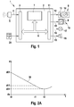
- FIG. 1 shows a device 1 with a distance and speed controller 2, which has an input circuit 3.
- a distance sensing device such as a radar or Lidarsensor 5
- the radar or lidar sensor 5 emits radar or laser radiation, which is reflected in part on objects. Reflected radiation is received by the radar or lidar sensor 5. In the case of a radar sensor, the radar radiation may have FMCW modulation or pulse modulation.
- the radar or Lidarsensor 5 generates output signals from measured received signals, which are supplied to the distance and speed controller 2 as input signals. These signals include magnitudes d of the objects as well as relative velocities Vrel of the objects with respect to the distance and speed controlled vehicle.
- the objects are also referred to as target objects or third-party vehicles. These quantities are supplied to the input circuit 3 and forwarded to a processing device 7 by means of a data exchange system 6, which may be, for example, a CAN bus.
- This processing device 7 may be, for example, a microprocessor or a signal processor in which variables and control variables are formed from the variables measured by the sensor 5.
- the processing device 7 determines from the relative position of the objects detected by the sensor 5 as well as their distance d and their relative speed Vrel at least one target object, which is of particular relevance for the distance and speed control, since this target object influences the output variables in a particular degree.
- the processing device 7 generates control signals for a deceleration device 8 of the vehicle, control signals for a performance-determining actuator 9 of a vehicle drive unit 10, which can be configured, for example, as a throttle actuator 9 or as a fuel injection pump 9, and signals for activating or deactivating a takeover request for the driver of the vehicle ,
- These output signals generated by the processing device 7 are output to an output circuit 11 by means of the data exchange system 6.
- a delay signal is output via an electrically conductive connection 12 to the delay device 8 of the vehicle.
- This delay signal is usually supplied to a brake drive device 13 which actuates brakes 14 of the vehicle in accordance with the deceleration signal.
- an acceleration signal which is the power-determining actuator 9 of the vehicle drive unit 10 is supplied.
- the vehicle drive unit 10 is influenced in a corresponding manner according to the controller output variables.
- a takeover request signal can be output to an electrically conductive connection 16 via the output circuit 11, which is supplied to an optical takeover request device 17.
- This optical takeover requesting device 17 consists, for example, of a light source in the driver's field of vision or of a plain text display which is mounted in the driver's field of vision and visually signals to the driver that the delay capability is insufficient to permit a critical approach of the own vehicle to a target object prevent.
- the output circuit 11 may output a further strobe request signal via an electrically conductive connection 18 to an acoustic handover requestor 19.
- This acoustic takeover request device 19 can be, for example, a buzzer or a ringtone in the vehicle interior, or it can be a voice output device that prompts the driver for a delay intervention.
- values for a desired driving speed can be entered by the driver and a comfort program can be set which permits sporty or relaxed driving.
- the distance and speed controller 2 is often designed as a comfort system and the deceleration dynamics that the distance and speed controller 2 can control is often limited to 2 to 3 m / sec 2 . It is assumed that the delay capability of the system is limited to a maximum of 3 m / sec 2 .
- a second deceleration capability is motor vehicle and driver dependent. It is determined experimentally and corresponds to a braking behavior of an average driver. It is therefore also referred to as medium delay. This can be designed as a constant or time-dependent.
- the absolute value of a mean deceleration is above the absolute value of 3 m / sec 2 and below the absolute value of full braking.
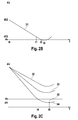
- FIG. 2A shows a graph with a graph 30, in which the distance between two vehicles is plotted over time.
- a first period of time defined by times t0 and t1 describes a reaction time of the driver. During this period, the other vehicle and the own vehicle approach each other by a distance d01-d11.
- a second period of time defined by times t1 and t3, describes an average deceleration in which the vehicle decelerates smoothly. At time t3, the two vehicles are closest, then they move away from each other again. The time t3 determines a culmination point.
- FIG. 2B shows a graph with a graph 31, in which the distance between two vehicles over time for a critical approach is plotted.
- the first time period defined by times t0 and t1
- the second period of time defined by times t1 and t3, also describes the average deceleration in which the vehicle decelerates smoothly.
- the time t3 describes a culmination point.
- the first two summands describe the distance between the two vehicles after the reaction time
- the third and the fourth summand describe the distance traveled during braking.
- a warning is issued when a safe distance is undershot, in particular when a collision can not be avoided if dmin is less than or equal to zero.
- the adjustable safety distance then forms the threshold, which must not be less than or should.
- the safety distance ds can also be set to zero.
- the approximation of the two vehicles is described by means of the two defined values, namely the reaction time treak and the mean delay ⁇ FZG, also referred to as application parameters.
- FIG. 2C shows a graph with graphs 32, 33 and 34.
- a constant ds is entered on the ordinate, which defines a safety distance.
- the graph 34 describes the distance between two vehicles, which are expected to approach a future time t4 to a safety distance of ds. Because the safety distance from ds is to be maintained, a warning is issued. A maximum approximation is given at a culmination point 35 at time t5 with a distance of dK.
Abstract
Description
Die vorliegende Erfindung betrifft ein Verfahren und eine Vorrichtung zur Benachrichtigung des Fahrers eines Kraftfahrzeugs, das mit einer Abstandsfühleinrichtung und einem adaptivem Abstands- und Geschwindigkeitsregler ausgestattet ist, in dem eine Übernahmeaufforderung aktiviert wird, die dem Fahrer mitteilt, dass eine kritische Annäherung an ein Zielobjekt erfolgt.The present invention relates to a method and a device for informing the driver of a motor vehicle, which is equipped with a distance sensing device and an adaptive distance and speed controller, in which a takeover request is activated, which notifies the driver that a critical approach to a target object takes place ,
Aus der
Aus der
Da insbesondere die Möglichkeit eines Spurwechsels des eigenen Fahrzeugs in den aktuellen Systemen nicht berücksichtigt wird, wird eine Übernahmeaufforderung in gewöhnlichen Fahrsituationen tendenziell zu früh ausgegeben. Die zur Verfügung stehenden Parameter für die Warnung aufgrund der Systemgrenze bieten lediglich die Möglichkeit, die Warnschwelle insgesamt abzusenken, was wiederum dazu führt, dass in wirklich kritischen Situationen zu spät gewarnt wird. Die Parametrierung der Warnung aufgrund des Abstandes zum Fremdfahrzeug beruht nicht auf physikalischen Grundsätzen und ist somit nur mit extrem hohem Zeitaufwand so einzustellen, dass sich die Übernahmeaufforderung in allen Fahrsituationen wie gewünscht verhält.In particular, since the possibility of a lane change of the own vehicle is not taken into account in the current systems, a takeover request in ordinary driving situations tends to be issued too early. The available parameters for the system limit warning only provide the opportunity to lower the warning threshold altogether, which in turn leads to being warned too late in truly critical situations. The parameterization of the warning due to the distance to the other vehicle is not based on physical principles and must therefore be set only with extremely high expenditure of time so that the takeover request behaves as desired in all driving situations.
Der Erfindung liegt von daher die Aufgabe zugrunde, ein verbessertes Verfahren und eine entsprechende Vorrichtung dazu anzugeben. Insbesondere soll eine Übernahmeaufforderung dargestellt werden, die basierend auf den Empfindungen des Fahrers genau in den Situationen warnt, in welchen ein über gewöhnliche Fahraufgaben mit ACC hinausgehendes Eingreifen des Fahrers notwendig wird. Gewöhnliche Fahraufgaben sind unter anderem die Lenkung des Fahrzeuges, Blinker setzen, Beobachtung des übrigen Verkehrs und so weiter.The invention is therefore based on the object to provide an improved method and a corresponding device thereto. In particular, a takeover request is to be presented which warns based on the driver's sensations precisely in the situations in which intervention by the driver beyond ordinary driving tasks with ACC becomes necessary. Common driving tasks include the steering of the vehicle, turn signals, observation of other traffic and so on.
Diese Aufgabe wird mit den Merkmalen der Hauptansprüche gelöst. Die Erfindung ist durch folgende Verfahrensschritte gekennzeichnet: ein Abstandswert für einen Abstand zwischen dem Kraftfahrzeug und einem Zielobjekt wird ermittelt, ein erster Streckenwert für eine Fahrerreaktionszeit wird ermittelt, ein zweiter Streckenwert für eine Verzögerung wird ermittelt, aus dem Abstandswert und den Streckenwerten wird ein voraussichtlicher Abstandswert ermittelt, der voraussichtlicher Abstandswert wird mit einem Schwellwert verglichen und unterschreitet der voraussichtlicher Abstandswert den Schwellwert, wird die Übernahmeaufforderungseinrichtung aktiviert. In der Abstandsfühleinrichtung der Vorrichtung ist also ein Abstandswert für einen Abstand zwischen dem Kraftfahrzeug und einem Zielobjekt ermittelbar, in dem adaptiven Abstands- und Geschwindigkeitsregler der Vorrichtung ist ein erster Streckenwert für eine Fahrerreaktionszeit, ein zweiter Streckenwert für eine Verzögerung, aus dem Abstandswert und den Streckenwerten ein voraussichtlicher Abstandswert ermittelbar und der voraussichtliche Abstandswert mit einem Schwellwert vergleichbar und die Übernahmeaufforderungseinrichtung der Vorrichtung ist dann aktivierbar, wenn der Abstandswert den Schwellwert unterschreitet. Der Kern der Erfindung basiert darauf, dass die Aktivierung der Übernahmeaufforderung in Abhängigkeit einer Fahrerreaktionszeit und einer Verzögerung erfolgt. Es wird dann gewarnt, wenn zur Vermeidung einer Kollision vom Fahrer eine Bremsung mit einer Verzögerung, auch als Mindestverzögerung bezeichnet, eingeleitet werden muss. Außerdem wird berücksichtigt, dass der Fahrer eine Reaktionszeit benötigt, um diese Bremsung zu beginnen. Die Reaktionszeit des Fahrers sowie die vom Fahrer zu erreichende Mindestverzögerung werden hierbei als Applikationsparameter zur Verfügung gestellt.This object is achieved with the features of the main claims. The invention is characterized by the following method steps: a distance value for a distance between the motor vehicle and a target object is determined, a first route value for a driver reaction time is determined, a second distance value for a deceleration is determined, an expected distance value is determined from the distance value and the distance values, the prospective distance value is compared with a threshold value, and if the prospective distance value falls below the threshold value, the transfer request device is activated. In the distance sensing device of the device, therefore, a distance value for a distance between the motor vehicle and a target object can be determined, in the adaptive distance and speed controller of the device is a first distance value for a driver reaction time, a second distance value for a delay, from the distance value and the distance values a probable distance value can be determined and the probable distance value can be compared to a threshold value, and the transfer request device of the device can be activated if the distance value falls below the threshold value. The gist of the invention is based on activating the takeover request in response to a driver response time and a delay. It is then warned if to avoid a collision by the driver braking with a delay, also referred to as a minimum delay, must be initiated. It also takes into account that the driver needs a response time to begin this braking. The reaction time of the driver as well as the minimum deceleration to be achieved by the driver are provided here as application parameters.
Der Fahrer erwartet eine Übernahmeaufforderung, wenn die aktuelle Fahrsituation ein sofortiges Eingreifen des Fahrers erfordert. Erkennt das System eine Situation, welche vom System zwar nicht beherrscht werden kann, in welcher jedoch ein Eingreifen des Fahrers zu einem späteren Zeitpunkt ausreicht, so soll noch keine Übernahmeaufforderung ausgegeben werden. Das Eingreifen des Fahrers kann durch Einleiten einer Bremsung oder durch ein Ausweichmanöver geschehen. Da vom ACC-System nicht erkannt werden kann, ob ein Ausweichmanöver möglich ist und ein Ausweichmanöver in kritischen Situationen auch später eingeleitet werden kann als ein Bremsmanöver, soll eine Warnung aufgrund einer notwendigen Bremsung erfolgen. Es wird ein typischer Bremsvorgang definiert. Reicht dieser definierte Bremsvorgang nicht aus, um eine Kollision zu vermeiden, soll eine Warnung ausgegeben werden. Damit wird erreicht, dass ein Fahrereingreifen über ein gewöhnliches Maß hinaus erforderlich ist. Das bedeutet, dass der Fahrer dem Verkehr wieder volle Aufmerksamkeit zu widmen hat.The driver expects a takeover request if the current driving situation requires immediate intervention by the driver. If the system detects a situation that can not be mastered by the system but in which intervention by the driver is sufficient at a later point in time, then no takeover request is yet to be issued. The intervention of the driver may be by initiating a braking or done by an evasive maneuver. Since the ACC system can not detect whether an evasive maneuver is possible and an evasive maneuver can be initiated later in critical situations than a braking maneuver, a warning should be given due to a necessary braking. A typical braking process is defined. If this defined braking process is not sufficient to avoid a collision, a warning should be issued. This ensures that driver intervention beyond an ordinary level is required. This means that the driver has to pay full attention to the traffic again.
In vorteilhafter Weise wird davon ausgegangen, dass die Verzögerung abhängig ist von der Geschwindigkeit des Fahrzeugs. Die Verzögerung bleibt während des Bremsvorganges konstant. Zugrunde gelegt wird allerdings die Geschwindigkeit, die während des Zeitpunktes der Detektion gefahren wird. Bei höherer Geschwindigkeit wird stärker abgebremst.Advantageously, it is assumed that the delay depends on the speed of the vehicle. The deceleration remains constant during the braking process. However, the speed that is used during the time of detection is taken as a basis. At higher speeds, braked more.
In vorteilhafter Weise wird anstelle einer Bremsung mit konstanter Verzögerung ein zeitabhängiger Bremsverlauf definiert. Mit zunehmender Zeit wird die negative Beschleunigung größer. Die Reaktionszeit kann in diesem Fall in diesem Verlauf integriert werden. In vorteilhafter Weise ist der Bremsverlauf sowohl abhängig von der Geschwindigkeit des Eigenfahrzeugs als auch zeitabhängig.Advantageously, a time-dependent braking process is defined instead of braking with a constant deceleration. As time goes on, the negative acceleration gets bigger. The reaction time can be integrated in this case in this process. Advantageously, the braking course is dependent both on the speed of the own vehicle and time-dependent.
In vorteilhafter Weise ist ein Schwellwert und damit ein Sicherheitsabstand einstellbar. Eine Warnung wird bereits ausgegeben, wenn der definierte Bremsverlauf nicht ausreicht, um innerhalb eines Sicherheitsabstandes zum Vordermann die Relativgeschwindigkeit abzubauen.Advantageously, a threshold and thus a safety distance is adjustable. A warning is already issued if the defined braking process is not sufficient to reduce the relative speed within a safety distance to the vehicle in front.
In vorteilhafter Weise wird als Ausgangsposition nicht davon ausgegangen, dass sich das Fremdfahrzeug mit konstanter Geschwindigkeit bewegt. Es wird eine maximal mögliche Änderung der Geschwindigkeit des Fremdfahrzeuges definiert. Dadurch ergibt sich ein Unsicherheitsbereich um die berechnete Position des Fremdfahrzeuges während des Bremsvorgangs des Eigenfahrzeugs. Als Bedingung für eine Warnung wird in diesem Fall ein Eintreten in diesen Unsicherheitsbereich verwendet.Advantageously, it is not assumed as the starting position that the other vehicle moves at a constant speed. A maximum possible change in the speed of the other vehicle is defined. This results in an area of uncertainty about the calculated position of the other vehicle during the braking process of the own vehicle. As a condition for a warning, an entry into this uncertainty area is used in this case.
Alternativ dazu kann auch von der aktuellen Relativgeschwindigkeit und - beschleunigung ausgegangen werden und eine maximal mögliche Änderung der Beschleunigung des Fremdfahrzeuges definiert werden. Daraus ergibt sich wiederum der Unsicherheitsbereich der Position des Fremdfahrzeuges innerhalb dessen sich das Fahrzeug in Zukunft befinden kann. Ein Eintreten in diesen Bereich führt zu einer Warnung.Alternatively, the current relative speed and acceleration can also be assumed, and a maximum possible change in the acceleration of the other vehicle can be defined. This in turn results in the uncertainty range of the position of the other vehicle within which the vehicle may be located in the future. Entering this area leads to a warning.
Die Fahrerübernahmeaufforderung kann mit wenigen Parametern auf unterschiedliche Verhaltenswünsche angepasst werden.The driver takeover request can be adapted to different behavioral requirements with a few parameters.
Zum besseren Verständnis der Erfindung werden nachstehend Ausführungsbeispiele anhand der Zeichnung näher erläutert.For a better understanding of the invention embodiments are explained below with reference to the drawing.
Es zeigen
- Fig. 1
- ein Blockschaltbild einer Vorrichtung mit einer Abstandsfühleinrichtung, einem Abstands- und Geschwindigkeitsregler, einer Verzögerungseinrichtung, einer Fahrzeugantriebseinheit, einem Sensor, einem Bedienfeld und zwei Übernahmeaufforderungseinrichtungen,
- Fig. 2A
- ein Diagramm mit einem Abstand zweier Fahrzeuge aufgetragen über die Zeit in einer unkritischen Situation,
- Fig. 2B
- ein zweites Diagramm mit einem Abstand zweier Fahrzeuge aufgetragen über die Zeit in einer kritischen Situation und
- Fig. 2C
- ein Diagramm mit einem Abstand zweier Fahrzeuge aufgetragen über die Zeit mit einem Sicherheitsabstand.
- Fig. 1
- 1 is a block diagram of a device having a distance sensor, a distance and speed controller, a deceleration device, a vehicle drive unit, a sensor, a control panel and two transfer request devices;
- Fig. 2A
- a diagram plotted with a distance of two vehicles over time in a noncritical situation,
- Fig. 2B
- a second graph plotted with a distance of two vehicles over time in a critical situation and
- Fig. 2C
- a diagram with a distance between two vehicles plotted over time with a safety margin.
Figur 1 zeigt eine Vorrichtung 1 mit einem Abstands- und Geschwindigkeitsregler 2, der über eine Eingangsschaltung 3 verfügt. Mittels elektrisch leitfähiger Verbindungen 4 werden der Eingangsschaltung 3 des Abstands- und Geschwindigkeitsreglers 2 Ausgangssignale von einer Abstandsfühleinrichtung wie einem Radar- oder Lidarsensor 5 zugeführt. Der Radar- oder Lidarsensor 5 sendet Radar- oder Laserstrahlung aus, die zum Teil an Objekten reflektiert wird. Reflektierte Strahlung wird von dem Radar- oder Lidarsensor 5 empfangen. Im Falle eines Radarsensors kann die Radarstrahlung eine FMCW-Modulation oder eine Pulsmodulation aufweisen. Der Radar- oder Lidarsensor 5 erzeugt aus gemessenen Empfangssignalen Ausgangssignale, die dem Abstands- und Geschwindigkeitsregler 2 als Eingangssignale zugeführt werden. Diese Signale beinhalten Größen Abstand d der Objekte sowie Relativgeschwindigkeiten Vrel der Objekte in Bezug auf das abstands- und geschwindigkeitsgeregelte Fahrzeug. Die Objekte sind auch als Zielobjekte oder Fremdfahrzeuge bezeichnet. Diese Größen werden der Eingangsschaltung 3 zugeführt und mittels eines Datenaustauschsystems 6, das beispielsweise ein CAN-Bus sein kann, an eine Verarbeitungseinrichtung 7 weitergeleitet. Diese Verarbeitungseinrichtung 7 kann beispielsweise ein Mikroprozessor oder ein Signalprozessor sein, in dem aus den vom Sensor 5 gemessenen Größen Stell- und Steuergrößen gebildet werden. Hierzu ermittelt die Verarbeitungseinrichtung 7 aus der relativen Position der vom Sensor 5 erkannten Objekte sowie deren Abstand d und deren Relativgeschwindigkeit Vrel mindestens ein Zielobjekt, das für die Abstands- und Geschwindigkeitsregelung von besonderer Relevanz ist, da dieses Zielobjekt in besonderem Maß die Ausgangsgrößen beeinflusst. So erzeugt die Verarbeitungseinrichtung 7 Steuersignale für eine Verzögerungseinrichtung 8 des Fahrzeugs, Steuersignale für ein leistungsbestimmendes Stellelement 9 einer Fahrzeugantriebseinheit 10, das beispielsweise als Drosselklappenstellglied 9 oder als Kraftstoffeinspritzpumpe 9 ausgebildet sein kann, sowie Signale zur Aktivierung bzw. Deaktivierung einer Übernahmeaufforderung für den Fahrer des Fahrzeugs. Diese von der Verarbeitungseinrichtung 7 erzeugten Ausgangssignale werden mittels des Datenaustauschsystems 6 auf eine Ausgangsschaltung 11 ausgegeben. Über die Ausgangsschaltung 11 wird ein Verzögerungssignal über eine elektrisch leitfähige Verbindung 12 an die Verzögerungseinrichtung 8 des Fahrzeugs ausgegeben. Dieses Verzögerungssignal wird üblicherweise einer Bremsenansteuereinrichtung 13 zugeführt, die Bremsen 14 des Fahrzeugs entsprechend dem Verzögerungssignal betätigt. Weiterhin wird von der Ausgangsschaltung 11 über eine elektrisch leitfähige Verbindung 15 ein Beschleunigungssignal ausgegeben, das dem leistungsbestimmenden Stellelement 9 der Fahrzeugantriebseinheit 10 zugeführt wird. Durch das Beschleunigungssignal wird die Fahrzeugantriebseinheit 10 in entsprechender Weise gemäß den Reglerausgangsgrößen beeinflusst. Weiterhin kann über die Ausgangsschaltung 11 ein Übernahmeaufforderungssignal auf eine elektrisch leitfähige Verbindung 16 ausgegeben werden, das einer optischen Übernahmeaufforderungseinrichtung 17 zugeführt wird. Diese optische Übernahmeaufforderungseinrichtung 17 besteht beispielsweise aus einer Lichtquelle im Sichtbereich des Fahrers oder aus einer Klartextanzeige, die im Sichtbereich des Fahrers angebracht ist und dem Fahrer visuell signalisiert, dass die Verzögerungsfähigkeit nicht ausreicht, um eine kritische Annäherung des eigenen Fahrzeugs an ein Zielobjekt zu verhindern. In ähnlicher Weise kann von der Ausgangsschaltung 11 ein weiteres Übernahmeaufforderungssignal über eine elektrisch leitfähige Verbindung 18 an eine akustische Übernahmeaufforderungseinrichtung 19 ausgegeben werden. Diese akustische Übernahmeaufforderungseinrichtung 19 kann beispielsweise ein Summer oder ein Klingelton im Fahrzeuginnenraum sein oder aber eine Sprachausgabeeinrichtung sein, die den Fahrer zu einem Verzögerungseingriff auffordert. Über ein Bedienfeld 20 sind seitens des Fahrers Werte für eine gewünschte Fahrgeschwindigkeit eingebbar und ein Komfortprogramm einstellbar, das ein sportliches oder ein entspanntes Fahren zulässt.FIG. 1 shows a device 1 with a distance and
Der Abstands- und Geschwindigkeitsregler 2 ist häufig als Komfortsystem ausgelegt und die Verzögerungsdynamik, die der Abstands- und Geschwindigkeitsregler 2 steuern kann, ist oftmals auf 2 bis 3 m/sek2 begrenzt. Es wird angenommen, dass die Verzögerungsfähigkeit des Systems also auf maximal 3 m/sek2 begrenzt ist. Eine zweite Verzögerungsfähigkeit ist kraftfahrzeug- und fahrerabhängig. Sie ist experimentell ermittelt und entspricht einem Bremsverhalten eines durchschnittlichen Fahrers. Sie wird deshalb auch als mittlere Verzögerung bezeichnet. Diese kann als Konstante oder zeitabhängig ausgelegt sein. Der absolute Wert einer mittleren Verzögerung liegt oberhalb des absoluten Wertes von 3 m/sek2 und unterhalb des absoluten Wertes einer Vollbremsung.The distance and
Das bedeutet, dass das System eine Verzögerung aufgrund eines vorausfahrenden Fremdfahrzeuges und der Systemverzögerungsfähigkeit einleitet, allerdings noch keine Übernahmeaufforderung ausgibt. Diese wird erst dann ausgegeben, wenn die mittlere Verzögerung nicht ausreicht, eine kritische Annäherung zu verhindern.This means that the system initiates a delay due to a preceding foreign vehicle and the system delay capability, but does not yet issue a takeover request. This is issued only when the mean delay is insufficient to prevent a critical approach.
Figur 2A zeigt ein Diagramm mit einem Graphen 30, in dem der Abstand zweier Fahrzeuge über die Zeit aufgetragen ist. Eine erste Zeitdauer, die durch die Zeitpunkte t0 und t1 definiert ist, beschreibt eine Reaktionszeit des Fahrers. Während dieser Zeitdauer nähern sich das Fremdfahrzeug und das eigene Fahrzeug um eine Strecke d01 - d11 aneinander an. Eine zweite Zeitdauer, die durch die Zeitpunkte t1 und t3 definiert ist, beschreibt eine mittlere Verzögerung, in der das Fahrzeug gleichmäßig abgebremst wird. Zum Zeitpunkt t3 sind sich die beiden Fahrzeuge am nächsten, danach entfernen sie sich wieder voneinander. Der Zeitpunkt t3 bestimmt einen Kulminationspunkt.FIG. 2A shows a graph with a
Figur 2B zeigt ein Diagramm mit einem Graphen 31, in dem der Abstand zweier Fahrzeuge über die Zeit für eine kritische Annäherung aufgetragen ist. Die erste Zeitdauer, die durch die Zeitpunkte t0 und t1 definiert ist, beschreibt ebenfalls die Reaktionszeit des Fahrers. Während dieser Zeitdauer nähern sich das Fremdfahrzeug und das eigene Fahrzeug um eine Strecke d02 - d12 aneinander an. Die zweite Zeitdauer, die durch die Zeitpunkte t1 und t3 definiert ist, beschreibt ebenfalls die mittlere Verzögerung, in der das Fahrzeug gleichmäßig abgebremst wird. Allerdings würden sich die Fahrzeuge zum Zeitpunkt t2 berühren. Eine solche kritische Annäherung soll verhindert sein. Der Zeitpunkt t3 beschreibt einen Kulminationspunkt.FIG. 2B shows a graph with a
Zum Zeitpunkt t0 beträgt der Abstand d0. Das Fremdfahrzeug bewegt sich vor dem eigenen Fahrzeug mit einer konstanten Relativgeschwindigkeit vrel, die kleiner als Null ist und damit nähern sich das Fremdfahrzeug und das eigene Fahrzeug aneinander an. Es wird eine Fahrerreaktionszeit treak und eine mittlere Verzögerung aFZG definiert, die einer negativen Relativverzögerung arel entspricht. Daraus ergibt sich eine erste Gleichung, die eine Distanz d zum Fahrzeug beschreibt. ![]()
![]()
Die ersten beiden Summanden beschreiben die Distanz zwischen beiden Fahrzeugen nach der Reaktionszeit, der dritte und der vierte Summand beschreiben die zurückgelegte Wegstrecke während der Bremsung.The first two summands describe the distance between the two vehicles after the reaction time, the third and the fourth summand describe the distance traveled during braking.
Daraus ergibt sich eine zweite Gleichung, die einen minimalen Abstand zum Fremdfahrzeug beschreibt: ![]()
![]()
Gewarnt wird, wenn ein Sicherheitsabstand unterschritten wird, insbesondere dann, wenn eine Kollision nicht vermieden werden kann, wenn dmin kleiner oder gleich Null ist. Der einstellbare Sicherheitsabstand bildet dann den Schwellwert, der nicht unterschritten werden darf beziehungsweise soll. Der Sicherheitsabstand ds ist auch zu Null setzbar.A warning is issued when a safe distance is undershot, in particular when a collision can not be avoided if dmin is less than or equal to zero. The adjustable safety distance then forms the threshold, which must not be less than or should. The safety distance ds can also be set to zero.
Damit ist die Näherung der beiden Fahrzeuge mittels der zwei definierten Werte, nämlich der Reaktionszeit treak und der mittleren Verzögerung äFZG, auch als Applikationsparameter bezeichnet, beschrieben.Thus, the approximation of the two vehicles is described by means of the two defined values, namely the reaction time treak and the mean delay αFZG, also referred to as application parameters.
Figur 2C zeigt ein Diagramm mit Graphen 32, 33 und 34. Auf der Ordinate ist eine Konstante ds eingetragen, die einen Sicherheitsabstand definiert. Der Graph 34 beschreibt den Abstand zweier Fahrzeuge, die sich voraussichtlich zu einem in der Zukunft liegenden Zeitpunkt t4 bis auf einen Sicherheitsabstand von ds annähern werden. Weil der Sicherheitsabstand von ds eingehalten werden soll, wird eine Warnung ausgegeben. Eine maximale Annäherung ist in einem Kulminationspunkt 35 zum Zeitpunkt t5 mit einem Abstand von dK gegeben.FIG. 2C shows a graph with
Claims (10)
Applications Claiming Priority (1)
| Application Number | Priority Date | Filing Date | Title |
|---|---|---|---|
| DE200510033522 DE102005033522A1 (en) | 2005-07-18 | 2005-07-18 | Method and device for informing the driver of a motor vehicle |
Publications (1)
| Publication Number | Publication Date |
|---|---|
| EP1746005A1 true EP1746005A1 (en) | 2007-01-24 |
Family
ID=36869854
Family Applications (1)
| Application Number | Title | Priority Date | Filing Date |
|---|---|---|---|
| EP06115653A Withdrawn EP1746005A1 (en) | 2005-07-18 | 2006-06-19 | Method and device for informing a driver of a motor vehicle |
Country Status (2)
| Country | Link |
|---|---|
| EP (1) | EP1746005A1 (en) |
| DE (1) | DE102005033522A1 (en) |
Families Citing this family (1)
| Publication number | Priority date | Publication date | Assignee | Title |
|---|---|---|---|---|
| DE102013225906A1 (en) * | 2013-12-13 | 2015-06-18 | Volkswagen Aktiengesellschaft | Motor vehicle with collision warning |
Citations (6)
| Publication number | Priority date | Publication date | Assignee | Title |
|---|---|---|---|---|
| US5014200A (en) * | 1990-02-20 | 1991-05-07 | General Motors Corporation | Adaptive cruise system |
| US5684473A (en) * | 1994-03-25 | 1997-11-04 | Nippondenso Co., Ltd. | Measuring apparatus for detecting distance between vehicles and related warning system |
| DE10015299A1 (en) | 2000-03-28 | 2001-10-04 | Bosch Gmbh Robert | Method and device for triggering a takeover request for ACC-controlled vehicles |
| FR2841518A1 (en) * | 2002-06-27 | 2004-01-02 | Peugeot Citroen Automobiles Sa | METHOD AND SYSTEM FOR ASSISTING THE DRIVING OF A MOTOR VEHICLE |
| DE10231687A1 (en) | 2002-07-10 | 2004-01-22 | Robert Bosch Gmbh | Method and device for notifying the driver of a motor vehicle |
| DE10335689A1 (en) * | 2002-08-01 | 2004-02-26 | Visteon Global Technologies, Inc., Dearborn | Driver alarm system for vehicles with adaptive cruise control |
-
2005
- 2005-07-18 DE DE200510033522 patent/DE102005033522A1/en not_active Withdrawn
-
2006
- 2006-06-19 EP EP06115653A patent/EP1746005A1/en not_active Withdrawn
Patent Citations (6)
| Publication number | Priority date | Publication date | Assignee | Title |
|---|---|---|---|---|
| US5014200A (en) * | 1990-02-20 | 1991-05-07 | General Motors Corporation | Adaptive cruise system |
| US5684473A (en) * | 1994-03-25 | 1997-11-04 | Nippondenso Co., Ltd. | Measuring apparatus for detecting distance between vehicles and related warning system |
| DE10015299A1 (en) | 2000-03-28 | 2001-10-04 | Bosch Gmbh Robert | Method and device for triggering a takeover request for ACC-controlled vehicles |
| FR2841518A1 (en) * | 2002-06-27 | 2004-01-02 | Peugeot Citroen Automobiles Sa | METHOD AND SYSTEM FOR ASSISTING THE DRIVING OF A MOTOR VEHICLE |
| DE10231687A1 (en) | 2002-07-10 | 2004-01-22 | Robert Bosch Gmbh | Method and device for notifying the driver of a motor vehicle |
| DE10335689A1 (en) * | 2002-08-01 | 2004-02-26 | Visteon Global Technologies, Inc., Dearborn | Driver alarm system for vehicles with adaptive cruise control |
Also Published As
| Publication number | Publication date |
|---|---|
| DE102005033522A1 (en) | 2007-01-25 |
Similar Documents
| Publication | Publication Date | Title |
|---|---|---|
| DE102004008888B4 (en) | Vehicle control system | |
| DE19514654B4 (en) | Collision alarm system for a motor vehicle | |
| EP1900589B1 (en) | Driver assistance system with warning function | |
| DE102009010006B4 (en) | Method and device for semi-autonomous or autonomous driving of a motor vehicle | |
| DE102007039039B4 (en) | Control of safety means of a motor vehicle | |
| EP3153376B1 (en) | Method and device for determining the adaptive reaction time of a driver of a motor vehicle | |
| DE102016101194A1 (en) | Vehicle brake control device | |
| DE102015122603A1 (en) | Advanced driver assistance system for vehicles | |
| DE102010049351A1 (en) | A method of operating a brake assist device and brake assist device for a vehicle | |
| DE102013102087A1 (en) | Method for operating a driver assistance system of a vehicle | |
| DE102015001971A1 (en) | Method and monitoring device for monitoring driver assistance systems | |
| EP3625092B1 (en) | Method for determining autonomous emergency braking, method for performing the emergency braking, and control device for a driving-dynamics system | |
| EP1521686B1 (en) | Method and device for notifying the driver of a motor vehicle | |
| DE102005014803A1 (en) | Collision avoiding system controlling method for motor vehicle, involves releasing signal by system when collision avoiding time falls below threshold value, and adapting value based on duration between warning signal and driver reaction | |
| DE102019108502B4 (en) | Method and control device for controlling an automatic emergency braking system | |
| EP1853454A1 (en) | Method for recognising an imminent overtake | |
| DE102010008208A1 (en) | A method for preventing collisions or reducing a collision strength of a vehicle | |
| EP3148855B1 (en) | Determining a critical vehicle state | |
| DE102018213262A1 (en) | Method for operating a motor vehicle, in particular a motorcycle, computer program | |
| DE102016224061A1 (en) | Lane change assistance system with relatively speed-dependent reaction area | |
| EP3475131B1 (en) | Emergency braking system for a vehicle and method for controlling the emergency braking system | |
| EP1665198B1 (en) | Method and device for emitting warning | |
| EP2054281B1 (en) | Actuation of safety means of a motor vehicle | |
| EP2054280B1 (en) | Actuation of safety means of a motor vehicle | |
| EP1426906A1 (en) | Warning strategy during lane recognition by a vehicle |
Legal Events
| Date | Code | Title | Description |
|---|---|---|---|
| PUAI | Public reference made under article 153(3) epc to a published international application that has entered the european phase |
Free format text: ORIGINAL CODE: 0009012 |
|
| AK | Designated contracting states |
Kind code of ref document: A1 Designated state(s): AT BE BG CH CY CZ DE DK EE ES FI FR GB GR HU IE IS IT LI LT LU LV MC NL PL PT RO SE SI SK TR |
|
| AX | Request for extension of the european patent |
Extension state: AL BA HR MK YU |
|
| 17P | Request for examination filed |
Effective date: 20070724 |
|
| AKX | Designation fees paid |
Designated state(s): DE FR GB IT |
|
| 17Q | First examination report despatched |
Effective date: 20070919 |
|
| STAA | Information on the status of an ep patent application or granted ep patent |
Free format text: STATUS: THE APPLICATION IS DEEMED TO BE WITHDRAWN |
|
| 18D | Application deemed to be withdrawn |
Effective date: 20080401 |