EP1745565B1 - Communication system, primary station and method of transmit power control - Google Patents
Communication system, primary station and method of transmit power control Download PDFInfo
- Publication number
- EP1745565B1 EP1745565B1 EP05733772.7A EP05733772A EP1745565B1 EP 1745565 B1 EP1745565 B1 EP 1745565B1 EP 05733772 A EP05733772 A EP 05733772A EP 1745565 B1 EP1745565 B1 EP 1745565B1
- Authority
- EP
- European Patent Office
- Prior art keywords
- signal
- indication
- station
- transmitting
- transmit power
- Prior art date
- Legal status (The legal status is an assumption and is not a legal conclusion. Google has not performed a legal analysis and makes no representation as to the accuracy of the status listed.)
- Active
Links
Images

Classifications
-
- H—ELECTRICITY
- H04—ELECTRIC COMMUNICATION TECHNIQUE
- H04W—WIRELESS COMMUNICATION NETWORKS
- H04W52/00—Power management, e.g. TPC [Transmission Power Control], power saving or power classes
- H04W52/04—TPC
- H04W52/30—TPC using constraints in the total amount of available transmission power
- H04W52/32—TPC of broadcast or control channels
- H04W52/327—Power control of multicast channels
-
- H—ELECTRICITY
- H04—ELECTRIC COMMUNICATION TECHNIQUE
- H04B—TRANSMISSION
- H04B7/00—Radio transmission systems, i.e. using radiation field
- H04B7/005—Control of transmission; Equalising
Definitions
- the invention relates to a communication system comprising a primary station and a plurality of secondary stations, to a primary station for use therein, and to a method of transmit power control in such a communication system.
- a radio communication system comprising a primary station and a plurality of secondary stations, for example a mobile phone system
- transmissions from a primary station to a secondary station take place on a downlink channel and transmissions from a secondary station to a primary station take place on an uplink channel.
- TPC transmit power control
- a separate power control loop is operated for each secondary station.
- Each secondary station determines the quality of its respective downlink signal and transmits TPC commands according to its prevailing channel conditions, and the transmit power is controlled individually for each secondary station.
- MBMS Multimedia Broadcast Multicast Service
- UMTS Universal Mobile Telecommunication System
- One way of operating point-to-multipoint transmission is to transmit at a constant power level on the downlink, at a power level sufficient for the secondary stations experiencing the poorest reception conditions to receive the data.
- Such a scheme is wasteful of power and may cause interference.
- a more efficient way of operating is to adapt the point-to-point downlink closed-loop transmit power control scheme to the point-to-multipoint scenario.
- One way of doing this is for each participating secondary station to measure the quality of a point-to-multipoint power-controlled downlink signal and to transmit TPC commands to the primary station.
- the primary station receives the TPC commands from each secondary station and decides on a transmit power level that will satisfy all, or at least the majority, of the secondary stations. Using such a scheme, the primary station may be able to use a lower transmit power when all the participating secondary stations are experiencing good reception conditions.
- sufficient channel resources i.e. time, frequency or codes, must be allocated for the participating secondary stations to transmit their TPC commands in individual channels.
- European Patent Application No. EP 0 999 656 discloses a communication system where mobile stations, after reception of a multicast message from a base station, transmit a power increment requesting signal when it is determined that the reception power of the multicast message is not sufficient.
- a plurality of receivers transmit power control information regarding a received multicast data signal. If all the receivers indicate that the transmission power level of the multicast message, the transmission power level is decreased.
- the US Patent Application US 2003/0119452 A1 describes a method for controlling transmission power of a plurality of user equipments (UEs) by a Node B to perform broadcasting in a mobile communication system including the Node B and the UEs capable of communicating with the Node B in a cell occupied by the Node B.
- the Node B is capable of broadcasting common information to specified UEs among the plurality of UEs.
- the US Patent Application US2003/0224813 A1 discloses a method for adjusting transmission power at a base station (BS) in a telecommunication network having a mobile terminal, such as a User Equipment (UE), operatively connected to the base station.
- the UE measures a signal-to-inference ratio (SIR) and according to this measurement sends a transmission power control (TPC) command to the base station.
- SIR signal-to-inference ratio
- TPC transmission power control
- the base station may adjust its transmission power according to the TPC command sent by the UE with a certain power control step.
- the step size for adjusting the transmission power is selected in the BS according to the received TPC command.
- An object of the present invention is to provide an improved point-to-multipoint data transmission service.
- a secondary station as claimed in claim 11 for use in a communication system comprising a primary station and a plurality of secondary stations.
- the secondary station transmits the second signal only if the measured parameter of the received first signal satisfies a predetermined criterion. In another embodiment, the secondary station transmits the second signal whatever the result of the measurement.
- This embodiment also allows second signals of a single type to be transmitted with different probabilities depending on the measured parameter values.
- a radio communication system 50 comprising a primary station 100 and a plurality of secondary stations 200.
- the primary station 100 comprises a transmitter 110 for transmitting a first signal on a downlink 310, for example a broadcast data signal, to each secondary station 200.
- the transmitter 110 has an output coupled to an antenna 120 via coupling means 130 which may be, for example, a circulator or changeover switch.
- the coupling means 130 is also coupled to an input of a receiver 140 for receiving uplink 320 signals from the antenna 120.
- Coupled to the transmitter 110 and the receiver 140 is a control means ( ⁇ C) 150, for example a processor, for processing signals received from the secondary stations 200 and for deriving from the signals a power control signal.
- Coupled to the control means ( ⁇ C) 150 and the transmitter 110 is a power control means 160 for controlling the transmit power of the transmitter 110 in response to the power control signals derived by the control means 150.
- the secondary station 200 comprises a receiver 240 for receiving signals transmitted by the primary station 100 on the downlink 310.
- the receiver 240 has an input coupled to an antenna 220 via coupling means 230 which may be, for example, a circulator or changeover switch.
- the coupling means 230 is also coupled to an output of a transmitter 210 for transmitting uplink signals via the antenna 220.
- a control means ( ⁇ C) 250 for example a processor, for making measurements on signals received from the primary station 100 and for deriving from the measurements a second signal which is transmitted on the uplink 320 by the transmitter 210 for effecting power control at the primary station 100.
- a power control means 260 for controlling the transmit power of the transmitter 210 in response to power control commands received from the primary station 200.
- the primary station commences transmission of the first signal, via its transmitter 110, to each secondary station 200.
- the information conveyed by the first signal is intended for receipt by a plurality of secondary stations 200.
- Each secondary station wishing to receive the information implements the following steps.
- the first signal is received via the receiver 230.
- control means 250 of the secondary station 200 measures a parameter of the received first signal.
- the measured parameter may take any of many forms. Some examples of the measured parameter are signal-to-noise ratio (SNR), signal-to-interference ratio (SIR), signal level, bit error rate, block error rate, or a combination of these. A skilled person can readily identify other parameters which may be used instead of, or in combination with, the above example parameters.
- SNR signal-to-noise ratio
- SIR signal-to-interference ratio
- bit error rate bit error rate
- block error rate or a combination of these.
- the control means 250 derives from the measured parameter a second signal for transmission to the primary station 200 for the purpose of transmit power control.
- the information content of the second signal depends on the parameter that was measured.
- the second signal is transmitted by the transmitter 210.
- the receiver 140 of the primary station 100 receives each of the second signals transmitted by the secondary stations 200.
- control means 150 processes the received second signals and derives a power control signal.
- the control means 150 determines whether to increase the transmit power of the primary station 100, or to decrease it. Optionally, it may decide to leave the transmit power unchanged.
- the algorithm used to derive the power control signal depends on the type of indication included in the second signal. Examples of possible algorithms are as follows:
- the power control means 160 controls the transmit power of the transmitter 110 according to the power control signal derived by the control means 150.
- the transmission of the respective second signals comprises a plurality of the secondary stations 200 transmitting common signals in a common time period in a common frequency allocation. All secondary stations 200 transmitting the same indication on the uplink transmit using common signals, in the same time period in the same frequency allocation. Because a plurality of secondary stations 200 use the same channel resources (i.e. code, time, and frequency) for transmission of their respective second signals, fewer channel resources are required.
- channel resources i.e. code, time, and frequency
- the common second signals received in a common time period and common frequency allocation will be combined by the receiver 140. Because it is the combined signals that are detected by the receiver 140, the transmit power level of the uplink signals may be reduced, for example by the secondary station power control means 260 in response to TPC commands transmitted by the primary station 200.
- the primary station 100 may transmit a downlink, third signal to terminate incomplete uplink second signals, or to pre-empt the transmission of uplink second signals that have not yet commenced.
- this option may be applied when secondary stations 200 increase the transmit power during the second signal, for example by transmitting the second signal a plurality of times with progressively increasing transmit power, while awaiting said third signal or the expiry of a time period.
- the power increase may be, for example, a ramped increase or a stepped increase.
- the information-bearing part of the second signal may be transmitted after a number of preamble signals of progressively increasing transmit power, and on ceasing the transmission of the preamble signals in response to receipt of the third signal the secondary stations may not terminate transmission of the second signal but continue to transmit the information-bearing part of the second signal.
- the invention has been described with respect to controlling the transmit power. However the invention is also applicable to controlling other transmission characteristics instead of, or in addition to, controlling the transmit power. Such other additional characteristics may be, for example, bit rate, error control coding, modulation scheme.
Description
- The invention relates to a communication system comprising a primary station and a plurality of secondary stations, to a primary station for use therein, and to a method of transmit power control in such a communication system.
- In a radio communication system comprising a primary station and a plurality of secondary stations, for example a mobile phone system, transmissions from a primary station to a secondary station take place on a downlink channel and transmissions from a secondary station to a primary station take place on an uplink channel. It is known to use downlink closed-loop transmit power control in which a secondary station measures the quality of a received, power controlled downlink signal and transmits transmit power control (TPC) commands to the primary station so that an adequate, but not excessive, received signal level is maintained at the secondary station despite fluctuations in downlink channel conditions.
- In point-to-point communication where a plurality of secondary stations receive individually addressed information signals on the downlink a separate power control loop is operated for each secondary station. Each secondary station determines the quality of its respective downlink signal and transmits TPC commands according to its prevailing channel conditions, and the transmit power is controlled individually for each secondary station.
- There is a requirement to introduce point-to-multipoint transmission for providing broadcast services, such as Multimedia Broadcast Multicast Service (MBMS) in the Universal Mobile Telecommunication System (UMTS), in which the same data is transmitted on a downlink from a primary station to a plurality of secondary stations.
- One way of operating point-to-multipoint transmission is to transmit at a constant power level on the downlink, at a power level sufficient for the secondary stations experiencing the poorest reception conditions to receive the data. However, such a scheme is wasteful of power and may cause interference.
- A more efficient way of operating is to adapt the point-to-point downlink closed-loop transmit power control scheme to the point-to-multipoint scenario. One way of doing this is for each participating secondary station to measure the quality of a point-to-multipoint power-controlled downlink signal and to transmit TPC commands to the primary station. The primary station receives the TPC commands from each secondary station and decides on a transmit power level that will satisfy all, or at least the majority, of the secondary stations. Using such a scheme, the primary station may be able to use a lower transmit power when all the participating secondary stations are experiencing good reception conditions. When using such a power control scheme, sufficient channel resources, i.e. time, frequency or codes, must be allocated for the participating secondary stations to transmit their TPC commands in individual channels. With a large number of participating secondary stations, a large number of resources must be allocated.
European Patent Application No.EP 0 999 656 discloses a communication system where mobile stations, after reception of a multicast message from a base station, transmit a power increment requesting signal when it is determined that the reception power of the multicast message is not sufficient.
In International Patent Application No.WO 2004/013981 , a plurality of receivers transmit power control information regarding a received multicast data signal. If all the receivers indicate that the transmission power level of the multicast message, the transmission power level is decreased. - The US Patent Application
US 2003/0119452 A1 describes a method for controlling transmission power of a plurality of user equipments (UEs) by a Node B to perform broadcasting in a mobile communication system including the Node B and the UEs capable of communicating with the Node B in a cell occupied by the Node B. The Node B is capable of broadcasting common information to specified UEs among the plurality of UEs. - The US Patent Application
US2003/0224813 A1 discloses a method for adjusting transmission power at a base station (BS) in a telecommunication network having a mobile terminal, such as a User Equipment (UE), operatively connected to the base station. The UE measures a signal-to-inference ratio (SIR) and according to this measurement sends a transmission power control (TPC) command to the base station. The base station may adjust its transmission power according to the TPC command sent by the UE with a certain power control step. The step size for adjusting the transmission power is selected in the BS according to the received TPC command. - An object of the present invention is to provide an improved point-to-multipoint data transmission service.
- According to a first aspect of the invention there is provided a method of transmit power control in a communication system as claimed in claim 1.
- According to a second aspect of the invention there is provided a secondary station as claimed in claim 11 for use in a communication system comprising a primary station and a plurality of secondary stations.
- By permitting a plurality of secondary stations to transmit a common second signal in a common time period in a common frequency allocation, in other words to use common channel resources, fewer channel resources are required for power control. This has the advantage of leaving more channel resources available for other services. Furthermore, the primary station will receive the combination of the common signals, so the transmit power of the secondary stations can be reduced. This has the advantage of reducing interference.
- In one embodiment, the secondary station transmits the second signal only if the measured parameter of the received first signal satisfies a predetermined criterion. In another embodiment, the secondary station transmits the second signal whatever the result of the measurement.
- In a further embodiment, the secondary station is adapted to transmit any of a plurality of different second signals, the signal being selected in dependence on the result of the measurement of the parameter of the received first signal. Each of these different second signals are distinguished by using different codes, or being transmitted in different time periods, or being transmitted in different frequency allocations. A combination of these distinguishing characteristics may be used. In contrast, identical second signals transmitted by different secondary stations are transmitted using a common code, in a common time period in a common frequency allocation.
- In another embodiment, the transmission of a particular second signal may take place with a non-unity probability, where the probability of transmission may be dependent on the value of a measured parameter of the received first signal. The relationship between the transmission probabilities and the measured parameter values may be pre-determined, or signalled to the secondary station, or the transmission probability may be directly signalled to the secondary station. This embodiment reduces the number of second signals transmitted, thus reducing interference. If different transmission probabilities are applied for different second signals, this embodiment allows second signals of one type, such as those corresponding to poor reception quality, to be transmitted more often than those of a different type, such as those corresponding to good reception quality. This has the advantage that information needed to control the downlink reception quality by changing transmission power, can be made available to the primary station with fewer uplink transmissions, thus reducing interference. This embodiment also allows second signals of a single type to be transmitted with different probabilities depending on the measured parameter values.
- The invention will now be described, by way of example only, with reference to the accompanying drawings wherein;
-
Figure 1 is a block schematic diagram of a communication system; -
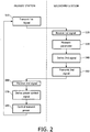
Figure 2 is a flow chart of a method of transmit power control; - Referring to
Figure 1 , there is illustrated aradio communication system 50 comprising aprimary station 100 and a plurality ofsecondary stations 200. Theprimary station 100 comprises atransmitter 110 for transmitting a first signal on adownlink 310, for example a broadcast data signal, to eachsecondary station 200. Thetransmitter 110 has an output coupled to anantenna 120 via coupling means 130 which may be, for example, a circulator or changeover switch. The coupling means 130 is also coupled to an input of areceiver 140 for receivinguplink 320 signals from theantenna 120. Coupled to thetransmitter 110 and thereceiver 140 is a control means (µC) 150, for example a processor, for processing signals received from thesecondary stations 200 and for deriving from the signals a power control signal. Coupled to the control means (µC) 150 and thetransmitter 110 is a power control means 160 for controlling the transmit power of thetransmitter 110 in response to the power control signals derived by the control means 150. - The
secondary station 200 comprises areceiver 240 for receiving signals transmitted by theprimary station 100 on thedownlink 310. Thereceiver 240 has an input coupled to anantenna 220 via coupling means 230 which may be, for example, a circulator or changeover switch. The coupling means 230 is also coupled to an output of atransmitter 210 for transmitting uplink signals via theantenna 220. Coupled to thetransmitter 210 and thereceiver 240 is a control means (µC) 250, for example a processor, for making measurements on signals received from theprimary station 100 and for deriving from the measurements a second signal which is transmitted on theuplink 320 by thetransmitter 210 for effecting power control at theprimary station 100. Optionally, coupled to the control means (µC) 250 and thetransmitter 210 is a power control means 260 for controlling the transmit power of thetransmitter 210 in response to power control commands received from theprimary station 200. - The operation of the
radio communication system 50 will now be described with reference to the flow chart ofFigure 2 . InFigure 2 , steps on the left hand side of the chart are performed by theprimary station 100, and steps on the right hand side are performed by eachsecondary station 200. - At
step 510 the primary station commences transmission of the first signal, via itstransmitter 110, to eachsecondary station 200. The information conveyed by the first signal is intended for receipt by a plurality ofsecondary stations 200. Each secondary station wishing to receive the information implements the following steps. - At
step 520 the first signal is received via thereceiver 230. - At
step 530 the control means 250 of thesecondary station 200 measures a parameter of the received first signal. - The measured parameter may take any of many forms. Some examples of the measured parameter are signal-to-noise ratio (SNR), signal-to-interference ratio (SIR), signal level, bit error rate, block error rate, or a combination of these. A skilled person can readily identify other parameters which may be used instead of, or in combination with, the above example parameters.
- At
step 540 the control means 250 derives from the measured parameter a second signal for transmission to theprimary station 200 for the purpose of transmit power control. The information content of the second signal depends on the parameter that was measured. Some examples, which can be used alone or in combination, are as follows: - a) Each uplink second signal may contain an indication, such as a TPC command, of whether the
secondary station 200 wants the downlink transmit power to be increased or decreased. Such an indication may be derived by comparing the value of the measured parameter with a threshold value. - b) Each uplink second signal may contain an indication of the value of the measured parameter, such as a bit error rate, block error rate, SNR, SIR, signal level; in some embodiments, the indication comprises an indication of whether the value of the measured parameter exceeds a threshold.
- c) Each uplink second signal may contain an indication of whether the
secondary station 200 decoded a downlink data packet successfully or with unrecoverable errors. - At
step 550 the second signal is transmitted by thetransmitter 210. - At
step 560 thereceiver 140 of theprimary station 100 receives each of the second signals transmitted by thesecondary stations 200. - At
step 570 the control means 150 processes the received second signals and derives a power control signal. At this step the control means 150 determines whether to increase the transmit power of theprimary station 100, or to decrease it. Optionally, it may decide to leave the transmit power unchanged. The algorithm used to derive the power control signal depends on the type of indication included in the second signal. Examples of possible algorithms are as follows: - a) The control means 150 may determine whether any
secondary station 200 requires a higher signal level in order to ensure reliable reception of the downlink first signal, and increase the transmit power if this is the case for anysecondary station 200. - b) The control means 150 may estimate the number of, or proportion of,
secondary stations 200 that require a higher signal level in order to ensure reliable reception of the downlink first signal, and increase the transmit power only if this number or proportion exceeds a threshold. Under these circumstances, somesecondary stations 200 experiencing poor reception conditions may remain with unreliable reception, at the choice of the control means 150. One way of distinguishing identical signals transmitted simultaneously from differentsecondary stations 200 is to examine the relative propagation delays indicated by different correlation peaks generated when detecting the second signals. - At
step 580 the power control means 160 controls the transmit power of thetransmitter 110 according to the power control signal derived by the control means 150. - Flow then returns to step 510 where the process is repeated while the first signal continues to be transmitted.
- According to the invention the transmission of the respective second signals comprises a plurality of the
secondary stations 200 transmitting common signals in a common time period in a common frequency allocation. Allsecondary stations 200 transmitting the same indication on the uplink transmit using common signals, in the same time period in the same frequency allocation. Because a plurality ofsecondary stations 200 use the same channel resources (i.e. code, time, and frequency) for transmission of their respective second signals, fewer channel resources are required. - The following examples illustrate some options for the uplink second signals:
- a) There may be two available uplink indications, corresponding to TPC commands. When a
secondary station 200 transmits a TPC command to either increase transmit power or decrease transmit power, the "up" command is transmitted as one second signal and the "down" command is transmitted as another second signal which is distinct from the "up" signal. The "up" command will be transmitted by all thosesecondary stations 200 requesting the power to be increased, and the "down" command will be transmitted by all thosesecondary stations 200 requesting the power to be decreased. These two different uplink second signals may be distinguished by using different codes, or being transmitted in different time periods, or by being transmitted in different frequency allocations. For example, the "up" and "down" commands may be transmitted in one time period and be distinguished by the use of different signal codes. As another example, the "up" commands may be transmitted in one time period and the "down" commands transmitted in a different time period, but use the same signal code. As another example, the "up" and "down" commands may be transmitted in one time period using the same signal code, and be distinguished by the use of different frequency allocations. A combination of these distinguishing characteristics may be used, for example different codes in combination with different time periods. - b) More than two distinct signals may be used, for example four, to represent different values of the measured parameter, such as four ranges of error rate or SIR. The signals may be distinguished by using four different codes, four different time periods, or four different frequency allocations.
- c) More than two distinct signals may be used, for example four, to represent "up" and "down" commands in combination with an indication of different grades of received signal level. In this example,
secondary stations 200 transmitting a "down" command transmit in a single time period, whereassecondary stations 200 transmitting an "up" command can indicate either a medium, low or a very low signal level and their transmissions may be segregated into three separate time periods, which can ease detection by theprimary station 100. - d) For one or more values of the measured parameter of the received first signal, the
secondary stations 200 may refrain from deriving or transmitting the second signal, which has the benefit of reducing interference and power consumption in thesecondary stations 200. For example, thesecondary stations 200 may transmit second signals corresponding to only "up" commands, refraining from transmitting "down" commands; in this case theprimary station 100 assumes a "down" value by default. As another example,secondary stations 200 may refrain from making an uplink transmission of the second signal if the measured parameter indicates that the quality of the received downlink first signal is below a threshold value; this can prevent the futile increase of transmit power and reduce interference when the reception conditions of thesecondary station 200 are too poor to be overcome by a power increase. Optionally, theprimary station 100 may transmit to thesecondary stations 200 an indication of a criterion that thesecondary stations 200 shall use to determine whether to refrain from deriving or transmitting the second signal. - e) The transmission of a particular second signal may take place with a sub-unity probability, which may be dependent on the value of a measured parameter of the received first signal. The relationship between the transmission probabilities and the measured parameter values may be pre-determined, or signalled to the secondary station.
- At the
primary station 200, the common second signals received in a common time period and common frequency allocation will be combined by thereceiver 140. Because it is the combined signals that are detected by thereceiver 140, the transmit power level of the uplink signals may be reduced, for example by the secondary station power control means 260 in response to TPC commands transmitted by theprimary station 200. - Optionally, when the
primary station 100 has received sufficient uplink information to decide on the downlink transmit power, theprimary station 100 may transmit a downlink, third signal to terminate incomplete uplink second signals, or to pre-empt the transmission of uplink second signals that have not yet commenced. In this way power consumption of thesecondary stations 200 can be reduced and interference reduced. In particular, this option may be applied whensecondary stations 200 increase the transmit power during the second signal, for example by transmitting the second signal a plurality of times with progressively increasing transmit power, while awaiting said third signal or the expiry of a time period. The power increase may be, for example, a ramped increase or a stepped increase. In some embodiments, the information-bearing part of the second signal may be transmitted after a number of preamble signals of progressively increasing transmit power, and on ceasing the transmission of the preamble signals in response to receipt of the third signal the secondary stations may not terminate transmission of the second signal but continue to transmit the information-bearing part of the second signal. - Throughout the specification and claims the invention has been described with respect to controlling the transmit power. However the invention is also applicable to controlling other transmission characteristics instead of, or in addition to, controlling the transmit power. Such other additional characteristics may be, for example, bit rate, error control coding, modulation scheme.
- In the present specification and claims the word "a" or "an" preceding an element does not exclude the presence of a plurality of such elements. Further, the word "comprising" does not exclude the presence of other elements or steps than those listed.
- The inclusion of reference signs in parentheses in the claims is intended to aid understanding and is not intended to be limiting.
Claims (18)
- A method of transmit power control for use in a communication system (50) comprising a primary station (100) and a plurality of secondary stations (200), the method comprising
at each secondary station (200):- receiving (520) a first signal transmitted by the primary station (100);- measuring (530) a parameter of the received first signal;- deriving (540) a second signal from the measured parameter;- transmitting (550) the second signal; andat the primary station (100):- transmitting (510) the first signal;- receiving (560) the second signals;- deriving (570) a power control signal from the received second signals;- controlling (580) the transmit power of the first signal in accordance with the power control signal;the method being characterized in that the transmission of the second signals comprises a plurality of the secondary stations (200) transmitting common signals in a common time period in a common frequency allocation, and wherein the transmitting of the second signal takes place with a sub-unity probability and wherein the probability is dependent on the value of the measured parameter of the received first signal. - A method as claimed in claim 1, wherein at each secondary station (200) deriving the second signal comprises selecting a combination of code, time period and frequency allocation from a plurality of combinations, the selection being dependent on a value of the measured parameter.
- A method as claimed in claim 2, wherein the plurality of combinations comprises different codes for transmission in a common time period.
- A method as claimed in claim 2, wherein the plurality of combinations comprises a common code for transmission in different time periods.
- A method as claimed in claim 2, wherein the plurality of combinations comprises a common code for transmission in a common time period using different frequency allocations.
- A method as claimed in any of claims 1 to 5, wherein each second signal comprises at least one of:- an indication to increase the transmit power;- an indication to decrease the transmit power;- an indication that the first signal was decoded successfully;- an indication that the first signal contained unrecoverable errors;- an indication that an error rate of the first signal exceeds a threshold value;- an indication of a quality level of the first signal.
- A method as claimed in claim 6, wherein the indication of a quality level comprises at least one of:- an indication of an error rate;- an indication of a signal-to-interference ratio;- an indication of a signal-to-noise ratio;- an indication of a signal level.
- A method as claimed in any of claims 1 to 7, comprising:at each secondary station (200), increasing transmit power during the second signal;at the primary station (100), in response to receiving a portion of the second signal, transmitting a third signal; andat each secondary station (200), in response to receiving the third signal, ceasing the power increase.
- A method as claimed in claim 8, wherein ceasing the power increase comprises ceasing transmission of the second signal.
- A secondary station (200), for use in a communication system comprising a primary station and a plurality of secondary stations, said secondary station comprising:- means (240) for receiving a first signal transmitted by the primary station (100);- means (250) for measuring a parameter of the received first signal;- means (250) for deriving a second signal from the measured parameter;means (210) for transmitting the second signal to the primary station for controlling the transmit power of the first signal; and
the secondary station being characterized in that the means (210) for transmitting the second signal are adapted to transmit a signal common to the plurality of secondary stations in a time period common to the plurality of secondary stations in a frequency allocation common to the plurality of secondary stations, wherein the means (210) for transmitting the second signal is adapted to transmit the second signal with a sub-unity probability and wherein the probability is dependent on the value of the measured parameter of the received first signal. - A communication system (50) comprising a primary station (100) and a plurality of secondary stations (200) as claimed in claim 10,
the primary station (100) comprising:- means (110) for transmitting the first signal;- means (140) for receiving the second signals;- means (150) for deriving a power control signal from the received second signals;- means (160) for controlling the transmit power of the first signal in accordance with the power control signal. - A communication system (50) as claimed in claim 11, wherein the means (250) for deriving the second signal is adapted to select a combination of code, time period and frequency allocation from a plurality of combinations, the selection being dependent on a value of the measured parameter.
- A communication system (50) as claimed in claim 12, wherein the plurality of combinations comprises different codes for transmission in a common time period.
- A communication system (50) as claimed in claim 12, wherein the plurality of combinations comprises a common code for transmission in different time periods.
- A communication system (50) as claimed in claim 12, wherein the plurality of combinations comprises a common code for transmission in a common time period using different frequency allocations.
- A communication system (50) as claimed in any of claims 11 to 15, wherein each second signal comprises at least one of:- an indication to increase the transmit power;- an indication to decrease the transmit power;- an indication that the first signal was decoded successfully;- an indication that the first signal contained unrecoverable errors;- an indication that an error rate of the first signal exceeds a threshold value;- an indication of a quality level of the first signal.
- A communication system (50) as claimed in claim 16, wherein the indication of a quality level comprises at least one of:- an indication of an error rate;- an indication of a signal-to-interference ratio;- an indication of a signal-to-noise ratio;- an indication of a signal level.
- A communication system (50) as claimed in any of claims 11 to 17, wherein:the secondary station means (210) for transmitting is adapted to increase its transmit power during the second signal;the primary station (100) comprises means (110, 140, 150), responsive to receiving a portion of the second signal, for transmitting a third signal; and the secondary station means (210) for transmitting is further adapted to, responsive to receiving the third signal, cease the power increase.
Applications Claiming Priority (3)
| Application Number | Priority Date | Filing Date | Title |
|---|---|---|---|
| GB0410109A GB0410109D0 (en) | 2004-05-06 | 2004-05-06 | Communication system, primary station and method of transit power control |
| GB0413394A GB0413394D0 (en) | 2004-05-06 | 2004-06-16 | Communication system, primary station and method of transmit power control |
| PCT/IB2005/051476 WO2005109674A1 (en) | 2004-05-06 | 2005-05-05 | Communication system, primary station and method of transmit power control |
Publications (2)
| Publication Number | Publication Date |
|---|---|
| EP1745565A1 EP1745565A1 (en) | 2007-01-24 |
| EP1745565B1 true EP1745565B1 (en) | 2017-08-02 |
Family
ID=34966278
Family Applications (1)
| Application Number | Title | Priority Date | Filing Date |
|---|---|---|---|
| EP05733772.7A Active EP1745565B1 (en) | 2004-05-06 | 2005-05-05 | Communication system, primary station and method of transmit power control |
Country Status (5)
| Country | Link |
|---|---|
| US (1) | US9078222B2 (en) |
| EP (1) | EP1745565B1 (en) |
| JP (1) | JP4977015B2 (en) |
| KR (1) | KR101158708B1 (en) |
| WO (1) | WO2005109674A1 (en) |
Families Citing this family (13)
| Publication number | Priority date | Publication date | Assignee | Title |
|---|---|---|---|---|
| US7409010B2 (en) | 2003-06-10 | 2008-08-05 | Shared Spectrum Company | Method and system for transmitting signals with reduced spurious emissions |
| KR100680958B1 (en) * | 2005-02-23 | 2007-02-09 | 주식회사 하이닉스반도체 | Method for manufacturing PMOS transistor |
| US8260340B2 (en) * | 2006-02-17 | 2012-09-04 | Alcatel Lucent | Methods of reverse link power control |
| US9538388B2 (en) * | 2006-05-12 | 2017-01-03 | Shared Spectrum Company | Method and system for dynamic spectrum access |
| US8326313B2 (en) * | 2006-05-12 | 2012-12-04 | Shared Spectrum Company | Method and system for dynamic spectrum access using detection periods |
| US8055204B2 (en) | 2007-08-15 | 2011-11-08 | Shared Spectrum Company | Methods for detecting and classifying signals transmitted over a radio frequency spectrum |
| US8027249B2 (en) | 2006-10-18 | 2011-09-27 | Shared Spectrum Company | Methods for using a detector to monitor and detect channel occupancy |
| US8997170B2 (en) | 2006-12-29 | 2015-03-31 | Shared Spectrum Company | Method and device for policy-based control of radio |
| US8184653B2 (en) | 2007-08-15 | 2012-05-22 | Shared Spectrum Company | Systems and methods for a cognitive radio having adaptable characteristics |
| WO2010022156A2 (en) | 2008-08-19 | 2010-02-25 | Shared Spectrum Company | Method and system for dynamic spectrum access using specialty detectors and improved networking |
| CN101860379B (en) * | 2010-06-02 | 2012-12-19 | 深圳国威电子有限公司 | Cordless telephone based on DECT and control method |
| GB2552783B (en) * | 2016-08-01 | 2022-09-21 | Dws Group Ltd | Communications method and system |
| US10936653B2 (en) | 2017-06-02 | 2021-03-02 | Apple Inc. | Automatically predicting relevant contexts for media items |
Citations (2)
| Publication number | Priority date | Publication date | Assignee | Title |
|---|---|---|---|---|
| US20030119452A1 (en) * | 2001-10-19 | 2003-06-26 | Samsung Electronics Co., Ltd. | Apparatus and method for controlling transmission power of downlink data channel in a mobile communication system supporting MBMS |
| US20030224813A1 (en) * | 2002-05-09 | 2003-12-04 | Nokia Corporation | Multiple level power control command signaling |
Family Cites Families (21)
| Publication number | Priority date | Publication date | Assignee | Title |
|---|---|---|---|---|
| DE3224691A1 (en) * | 1982-07-02 | 1984-01-05 | Chemische Werke Hüls AG, 4370 Marl | METHOD FOR PRODUCING HIGH MOLECULAR POLYPHENYLENE OXIDES |
| JPH0831838B2 (en) * | 1992-03-18 | 1996-03-27 | 国際電信電話株式会社 | Spread spectrum communication system |
| EP0846378B1 (en) * | 1995-08-22 | 1999-10-06 | Thomson-Csf | Method and device for spatial multiplexing-demultiplexing of radio signals for an sdma mobile radio system |
| JPH10173594A (en) * | 1996-12-06 | 1998-06-26 | Hitachi Ltd | Code division multiple access communication system and sending power control method |
| US6028851A (en) * | 1997-09-26 | 2000-02-22 | Telefonaktiebolaget L M Ericsson (Publ) | System and method for mobile assisted admission control |
| EP1013006A1 (en) * | 1998-07-13 | 2000-06-28 | Samsung Electronics Co., Ltd. | Power control device and method for reverse link common channel in mobile communication system |
| JP3248498B2 (en) | 1998-10-30 | 2002-01-21 | 日本電気株式会社 | Mobile communication system |
| EP1058407A1 (en) * | 1999-04-01 | 2000-12-06 | Alcatel | Transmit power correction in a mobile communication system |
| JP2001231062A (en) * | 2000-02-17 | 2001-08-24 | Nec Shizuoka Ltd | Mobile phone system and its hand-over method |
| GB0007337D0 (en) | 2000-03-28 | 2000-05-17 | Koninkl Philips Electronics Nv | Radio communication system |
| JP3424647B2 (en) * | 2000-04-04 | 2003-07-07 | 日本電気株式会社 | CDMA transceiver |
| JP2001292096A (en) * | 2000-04-06 | 2001-10-19 | Ntt Docomo Inc | Method for controlling outgoing transmission power in multi-cast transmission and base station |
| US6970438B2 (en) | 2001-02-16 | 2005-11-29 | Nokia Mobile Phones Ltd. | Method and device for downlink packet switching |
| US20030003905A1 (en) * | 2001-06-20 | 2003-01-02 | Shvodian William M. | System and method for providing signal quality feedback in a wireless network |
| JP3838487B2 (en) | 2001-08-10 | 2006-10-25 | 株式会社エヌ・ティ・ティ・ドコモ | Radio communication system, communication terminal apparatus, base station apparatus, and transmission power control method |
| US7006844B2 (en) | 2002-02-19 | 2006-02-28 | Nokia Corporation | Adaptive power control for multicast transmission |
| JP2003318816A (en) | 2002-04-18 | 2003-11-07 | Mitsubishi Electric Corp | Communication system, base station apparatus, mobile station apparatus and transmission power control method |
| JP2003333661A (en) * | 2002-05-15 | 2003-11-21 | Nec Corp | Mobile communication system, radio base station device and random access control method to be used therefor |
| KR20050026093A (en) | 2002-08-01 | 2005-03-14 | 인터디지탈 테크날러지 코포레이션 | Power control of point to multipoint physical channels |
| US20050232177A1 (en) | 2002-08-30 | 2005-10-20 | Koninklijke Philips Electronics N.V. | Method for transmission power control of a multicast signal |
| US8687607B2 (en) * | 2003-10-08 | 2014-04-01 | Qualcomm Incorporated | Method and apparatus for feedback reporting in a wireless communications system |
-
2005
- 2005-05-05 EP EP05733772.7A patent/EP1745565B1/en active Active
- 2005-05-05 WO PCT/IB2005/051476 patent/WO2005109674A1/en not_active Application Discontinuation
- 2005-05-05 KR KR1020067023154A patent/KR101158708B1/en active IP Right Grant
- 2005-05-05 JP JP2007512668A patent/JP4977015B2/en active Active
- 2005-05-05 US US11/568,544 patent/US9078222B2/en active Active
Patent Citations (2)
| Publication number | Priority date | Publication date | Assignee | Title |
|---|---|---|---|---|
| US20030119452A1 (en) * | 2001-10-19 | 2003-06-26 | Samsung Electronics Co., Ltd. | Apparatus and method for controlling transmission power of downlink data channel in a mobile communication system supporting MBMS |
| US20030224813A1 (en) * | 2002-05-09 | 2003-12-04 | Nokia Corporation | Multiple level power control command signaling |
Also Published As
| Publication number | Publication date |
|---|---|
| WO2005109674A1 (en) | 2005-11-17 |
| US9078222B2 (en) | 2015-07-07 |
| US20070165577A1 (en) | 2007-07-19 |
| JP2007536867A (en) | 2007-12-13 |
| KR101158708B1 (en) | 2012-06-22 |
| JP4977015B2 (en) | 2012-07-18 |
| EP1745565A1 (en) | 2007-01-24 |
| KR20070006892A (en) | 2007-01-11 |
Similar Documents
| Publication | Publication Date | Title |
|---|---|---|
| EP1745565B1 (en) | Communication system, primary station and method of transmit power control | |
| US11134520B2 (en) | Wireless communication system and method of controlling a transmission power | |
| US8271013B2 (en) | Method and arrangement for transmitting CQI on the uplink | |
| US7573838B2 (en) | Mobile communication system | |
| EP1630972B1 (en) | Communication terminal apparatus | |
| EP2364054B1 (en) | Communication terminal device, base station device and radio communication system | |
| EP1145461B1 (en) | Method and apparatus for power control based on the probability that the power control command is in error | |
| KR100533205B1 (en) | Mobile communication system, communication control method, base station and mobile station to be used in the same | |
| JP3248498B2 (en) | Mobile communication system | |
| EP1467499B1 (en) | Base station, mobile station, communication system, transmission control method, and mobile station control program | |
| US7680080B2 (en) | Method of using a mobile unit to determine whether to commence handover | |
| US20080037449A1 (en) | Method And System For Power Control During The Traffic Channel Initialization Period In A Cdma Network | |
| JP2011135595A (en) | Radio communication system, and method of controlling downlink transmission power or bit rate | |
| US20060166665A1 (en) | Radio communication system | |
| JP3526243B2 (en) | Base station apparatus and line quality deterioration prevention method | |
| KR100645511B1 (en) | Power/transmission-rate control method for shared forward link data channel in a cdma mobile communication system |
Legal Events
| Date | Code | Title | Description |
|---|---|---|---|
| PUAI | Public reference made under article 153(3) epc to a published international application that has entered the european phase |
Free format text: ORIGINAL CODE: 0009012 |
|
| 17P | Request for examination filed |
Effective date: 20061206 |
|
| AK | Designated contracting states |
Kind code of ref document: A1 Designated state(s): AT BE BG CH CY CZ DE DK EE ES FI FR GB GR HU IE IS IT LI LT LU MC NL PL PT RO SE SI SK TR |
|
| DAX | Request for extension of the european patent (deleted) | ||
| 17Q | First examination report despatched |
Effective date: 20091112 |
|
| RAP1 | Party data changed (applicant data changed or rights of an application transferred) |
Owner name: KONINKLIJKE PHILIPS N.V. |
|
| REG | Reference to a national code |
Ref country code: DE Ref legal event code: R079 Ref document number: 602005052448 Country of ref document: DE Free format text: PREVIOUS MAIN CLASS: H04B0007005000 Ipc: H04W0052320000 |
|
| GRAP | Despatch of communication of intention to grant a patent |
Free format text: ORIGINAL CODE: EPIDOSNIGR1 |
|
| RIC1 | Information provided on ipc code assigned before grant |
Ipc: H04W 52/32 20090101AFI20170206BHEP |
|
| INTG | Intention to grant announced |
Effective date: 20170224 |
|
| GRAS | Grant fee paid |
Free format text: ORIGINAL CODE: EPIDOSNIGR3 |
|
| GRAA | (expected) grant |
Free format text: ORIGINAL CODE: 0009210 |
|
| AK | Designated contracting states |
Kind code of ref document: B1 Designated state(s): AT BE BG CH CY CZ DE DK EE ES FI FR GB GR HU IE IS IT LI LT LU MC NL PL PT RO SE SI SK TR |
|
| REG | Reference to a national code |
Ref country code: GB Ref legal event code: FG4D |
|
| REG | Reference to a national code |
Ref country code: CH Ref legal event code: EP Ref country code: AT Ref legal event code: REF Ref document number: 915705 Country of ref document: AT Kind code of ref document: T Effective date: 20170815 |
|
| REG | Reference to a national code |
Ref country code: IE Ref legal event code: FG4D |
|
| REG | Reference to a national code |
Ref country code: DE Ref legal event code: R096 Ref document number: 602005052448 Country of ref document: DE |
|
| REG | Reference to a national code |
Ref country code: NL Ref legal event code: MP Effective date: 20170802 |
|
| REG | Reference to a national code |
Ref country code: AT Ref legal event code: MK05 Ref document number: 915705 Country of ref document: AT Kind code of ref document: T Effective date: 20170802 |
|
| REG | Reference to a national code |
Ref country code: LT Ref legal event code: MG4D |
|
| PG25 | Lapsed in a contracting state [announced via postgrant information from national office to epo] |
Ref country code: LT Free format text: LAPSE BECAUSE OF FAILURE TO SUBMIT A TRANSLATION OF THE DESCRIPTION OR TO PAY THE FEE WITHIN THE PRESCRIBED TIME-LIMIT Effective date: 20170802 Ref country code: SE Free format text: LAPSE BECAUSE OF FAILURE TO SUBMIT A TRANSLATION OF THE DESCRIPTION OR TO PAY THE FEE WITHIN THE PRESCRIBED TIME-LIMIT Effective date: 20170802 Ref country code: AT Free format text: LAPSE BECAUSE OF FAILURE TO SUBMIT A TRANSLATION OF THE DESCRIPTION OR TO PAY THE FEE WITHIN THE PRESCRIBED TIME-LIMIT Effective date: 20170802 Ref country code: NL Free format text: LAPSE BECAUSE OF FAILURE TO SUBMIT A TRANSLATION OF THE DESCRIPTION OR TO PAY THE FEE WITHIN THE PRESCRIBED TIME-LIMIT Effective date: 20170802 Ref country code: FI Free format text: LAPSE BECAUSE OF FAILURE TO SUBMIT A TRANSLATION OF THE DESCRIPTION OR TO PAY THE FEE WITHIN THE PRESCRIBED TIME-LIMIT Effective date: 20170802 |
|
| PG25 | Lapsed in a contracting state [announced via postgrant information from national office to epo] |
Ref country code: GR Free format text: LAPSE BECAUSE OF FAILURE TO SUBMIT A TRANSLATION OF THE DESCRIPTION OR TO PAY THE FEE WITHIN THE PRESCRIBED TIME-LIMIT Effective date: 20171103 Ref country code: BG Free format text: LAPSE BECAUSE OF FAILURE TO SUBMIT A TRANSLATION OF THE DESCRIPTION OR TO PAY THE FEE WITHIN THE PRESCRIBED TIME-LIMIT Effective date: 20171102 Ref country code: IS Free format text: LAPSE BECAUSE OF FAILURE TO SUBMIT A TRANSLATION OF THE DESCRIPTION OR TO PAY THE FEE WITHIN THE PRESCRIBED TIME-LIMIT Effective date: 20171202 Ref country code: PL Free format text: LAPSE BECAUSE OF FAILURE TO SUBMIT A TRANSLATION OF THE DESCRIPTION OR TO PAY THE FEE WITHIN THE PRESCRIBED TIME-LIMIT Effective date: 20170802 Ref country code: ES Free format text: LAPSE BECAUSE OF FAILURE TO SUBMIT A TRANSLATION OF THE DESCRIPTION OR TO PAY THE FEE WITHIN THE PRESCRIBED TIME-LIMIT Effective date: 20170802 |
|
| PG25 | Lapsed in a contracting state [announced via postgrant information from national office to epo] |
Ref country code: CZ Free format text: LAPSE BECAUSE OF FAILURE TO SUBMIT A TRANSLATION OF THE DESCRIPTION OR TO PAY THE FEE WITHIN THE PRESCRIBED TIME-LIMIT Effective date: 20170802 Ref country code: RO Free format text: LAPSE BECAUSE OF FAILURE TO SUBMIT A TRANSLATION OF THE DESCRIPTION OR TO PAY THE FEE WITHIN THE PRESCRIBED TIME-LIMIT Effective date: 20170802 Ref country code: DK Free format text: LAPSE BECAUSE OF FAILURE TO SUBMIT A TRANSLATION OF THE DESCRIPTION OR TO PAY THE FEE WITHIN THE PRESCRIBED TIME-LIMIT Effective date: 20170802 |
|
| REG | Reference to a national code |
Ref country code: DE Ref legal event code: R097 Ref document number: 602005052448 Country of ref document: DE |
|
| REG | Reference to a national code |
Ref country code: FR Ref legal event code: PLFP Year of fee payment: 14 |
|
| PG25 | Lapsed in a contracting state [announced via postgrant information from national office to epo] |
Ref country code: SK Free format text: LAPSE BECAUSE OF FAILURE TO SUBMIT A TRANSLATION OF THE DESCRIPTION OR TO PAY THE FEE WITHIN THE PRESCRIBED TIME-LIMIT Effective date: 20170802 Ref country code: EE Free format text: LAPSE BECAUSE OF FAILURE TO SUBMIT A TRANSLATION OF THE DESCRIPTION OR TO PAY THE FEE WITHIN THE PRESCRIBED TIME-LIMIT Effective date: 20170802 Ref country code: IT Free format text: LAPSE BECAUSE OF FAILURE TO SUBMIT A TRANSLATION OF THE DESCRIPTION OR TO PAY THE FEE WITHIN THE PRESCRIBED TIME-LIMIT Effective date: 20170802 |
|
| PLBE | No opposition filed within time limit |
Free format text: ORIGINAL CODE: 0009261 |
|
| STAA | Information on the status of an ep patent application or granted ep patent |
Free format text: STATUS: NO OPPOSITION FILED WITHIN TIME LIMIT |
|
| 26N | No opposition filed |
Effective date: 20180503 |
|
| PG25 | Lapsed in a contracting state [announced via postgrant information from national office to epo] |
Ref country code: SI Free format text: LAPSE BECAUSE OF FAILURE TO SUBMIT A TRANSLATION OF THE DESCRIPTION OR TO PAY THE FEE WITHIN THE PRESCRIBED TIME-LIMIT Effective date: 20170802 |
|
| REG | Reference to a national code |
Ref country code: CH Ref legal event code: PL |
|
| REG | Reference to a national code |
Ref country code: BE Ref legal event code: MM Effective date: 20180531 |
|
| PG25 | Lapsed in a contracting state [announced via postgrant information from national office to epo] |
Ref country code: MC Free format text: LAPSE BECAUSE OF FAILURE TO SUBMIT A TRANSLATION OF THE DESCRIPTION OR TO PAY THE FEE WITHIN THE PRESCRIBED TIME-LIMIT Effective date: 20170802 |
|
| REG | Reference to a national code |
Ref country code: IE Ref legal event code: MM4A |
|
| PG25 | Lapsed in a contracting state [announced via postgrant information from national office to epo] |
Ref country code: LI Free format text: LAPSE BECAUSE OF NON-PAYMENT OF DUE FEES Effective date: 20180531 Ref country code: CH Free format text: LAPSE BECAUSE OF NON-PAYMENT OF DUE FEES Effective date: 20180531 |
|
| PG25 | Lapsed in a contracting state [announced via postgrant information from national office to epo] |
Ref country code: LU Free format text: LAPSE BECAUSE OF NON-PAYMENT OF DUE FEES Effective date: 20180505 |
|
| PG25 | Lapsed in a contracting state [announced via postgrant information from national office to epo] |
Ref country code: IE Free format text: LAPSE BECAUSE OF NON-PAYMENT OF DUE FEES Effective date: 20180505 |
|
| PG25 | Lapsed in a contracting state [announced via postgrant information from national office to epo] |
Ref country code: BE Free format text: LAPSE BECAUSE OF NON-PAYMENT OF DUE FEES Effective date: 20180531 |
|
| PG25 | Lapsed in a contracting state [announced via postgrant information from national office to epo] |
Ref country code: TR Free format text: LAPSE BECAUSE OF FAILURE TO SUBMIT A TRANSLATION OF THE DESCRIPTION OR TO PAY THE FEE WITHIN THE PRESCRIBED TIME-LIMIT Effective date: 20170802 |
|
| PG25 | Lapsed in a contracting state [announced via postgrant information from national office to epo] |
Ref country code: PT Free format text: LAPSE BECAUSE OF FAILURE TO SUBMIT A TRANSLATION OF THE DESCRIPTION OR TO PAY THE FEE WITHIN THE PRESCRIBED TIME-LIMIT Effective date: 20170802 Ref country code: HU Free format text: LAPSE BECAUSE OF FAILURE TO SUBMIT A TRANSLATION OF THE DESCRIPTION OR TO PAY THE FEE WITHIN THE PRESCRIBED TIME-LIMIT; INVALID AB INITIO Effective date: 20050505 |
|
| PG25 | Lapsed in a contracting state [announced via postgrant information from national office to epo] |
Ref country code: CY Free format text: LAPSE BECAUSE OF FAILURE TO SUBMIT A TRANSLATION OF THE DESCRIPTION OR TO PAY THE FEE WITHIN THE PRESCRIBED TIME-LIMIT Effective date: 20170802 |
|
| PGFP | Annual fee paid to national office [announced via postgrant information from national office to epo] |
Ref country code: FR Payment date: 20230523 Year of fee payment: 19 Ref country code: DE Payment date: 20220628 Year of fee payment: 19 |
|
| PGFP | Annual fee paid to national office [announced via postgrant information from national office to epo] |
Ref country code: GB Payment date: 20230523 Year of fee payment: 19 |