EP1728533A1 - Medical device - Google Patents
Medical device Download PDFInfo
- Publication number
- EP1728533A1 EP1728533A1 EP06009378A EP06009378A EP1728533A1 EP 1728533 A1 EP1728533 A1 EP 1728533A1 EP 06009378 A EP06009378 A EP 06009378A EP 06009378 A EP06009378 A EP 06009378A EP 1728533 A1 EP1728533 A1 EP 1728533A1
- Authority
- EP
- European Patent Office
- Prior art keywords
- medical device
- modules
- selectively
- batteries
- control
- Prior art date
- Legal status (The legal status is an assumption and is not a legal conclusion. Google has not performed a legal analysis and makes no representation as to the accuracy of the status listed.)
- Granted
Links
Images


Classifications
-
- H—ELECTRICITY
- H02—GENERATION; CONVERSION OR DISTRIBUTION OF ELECTRIC POWER
- H02J—CIRCUIT ARRANGEMENTS OR SYSTEMS FOR SUPPLYING OR DISTRIBUTING ELECTRIC POWER; SYSTEMS FOR STORING ELECTRIC ENERGY
- H02J7/00—Circuit arrangements for charging or depolarising batteries or for supplying loads from batteries
- H02J7/0013—Circuit arrangements for charging or depolarising batteries or for supplying loads from batteries acting upon several batteries simultaneously or sequentially
- H02J7/0025—Sequential battery discharge in systems with a plurality of batteries
-
- H—ELECTRICITY
- H02—GENERATION; CONVERSION OR DISTRIBUTION OF ELECTRIC POWER
- H02J—CIRCUIT ARRANGEMENTS OR SYSTEMS FOR SUPPLYING OR DISTRIBUTING ELECTRIC POWER; SYSTEMS FOR STORING ELECTRIC ENERGY
- H02J7/00—Circuit arrangements for charging or depolarising batteries or for supplying loads from batteries
- H02J7/0029—Circuit arrangements for charging or depolarising batteries or for supplying loads from batteries with safety or protection devices or circuits
- H02J7/0031—Circuit arrangements for charging or depolarising batteries or for supplying loads from batteries with safety or protection devices or circuits using battery or load disconnect circuits
Definitions
- the present invention relates to medical devices, and more particularly to power distribution systems for medical devices such as pacemakers.
- Pacemaker systems typically include a controller, a battery, a pulse generator and one or more leads.
- the pulse generator produces pacing pulses for a heart.
- the leads deliver the impulses to the heart and sense contractions of the heart.
- a programming module that is separate from the pacemaker system can be used by the doctor to alter the operation of the pacemaker system after it has been installed in a patient.
- Some pacemaker systems operate on demand. In other words, the pacemaker system stands by until a natural rate of the upper and lower heart falls below a predetermined rate. When this situation occurs, the pacemaker system sends out pacing impulses to ensure that the heart contracts and pumps blood.
- the battery, controller, and pulse generator may be packaged in a sealed housing.
- the leads typically extend from the sealed housing and have ends that are connected within chambers of the patient's heart.
- the leads are also typically employed to carry feedback signals from the heart. Using the feedback signals, the controller is able to monitor the heart's activity and trigger the pulse generator appropriately.
- the battery may be sealed inside of the housing or another component of the pacemaker system. The housing and/or other component is typically removed and the battery is replaced when the stored energy in the battery falls below a threshold. As can be appreciated, replacing the battery requires a patient to undergo additional surgery.
- the leads typically include insulated wires that extend from the pulse generator in the housing through a vein to a heart chamber or chambers.
- the pacemaker system monitors the heart by sensing electrical signals received by the pulse generator through the leads. The signals that are received provide information relating to contraction of the heart chambers. This information is typically sufficient for the controller to decide when pulses are required.
- Pacemaker systems exist for single chamber and dual chamber applications.
- a single chamber pacemaker system usually employs a single lead to carry signals to and from one chamber of the heart.
- the lead is connected to the right atrium or the right ventricle.
- This type of pacemaker is often selected for patients having an SA (sinoatrial) node that sends out signals too slowly but whose electrical pathway to the lower heart is in good condition.
- SA sinoatrial
- a dual chamber pacemaker usually includes two leads. One lead is located in the right atrium and another lead is located in the right ventricle. This type of pacemaker system can monitor and deliver impulses to either or both of the heart chambers.
- the dual chamber pacemaker system is typically selected when the SA node signals are too slow and the electrical pathway is partly or completely blocked.
- Adaptive rate pacemakers may also be used.
- Adaptive rate pacemakers typically include additional sensors that monitor the body's need for blood flow. By monitoring this information, the pacemaker can increase and/or decrease the pace to correct for when the heart's natural rate does not increase sufficiently for an increased level of activity.
- a medical device comprises a pulse generator that selectively generates pulses.
- a control module selectively controls the pulses.
- a power distribution system supplies power to the medical device.
- the power distribution system includes N batteries, where N is an integer greater than one, a common node, and N protection modules that communicate with the control module.
- the N protection modules selectively connect a respective one of the N batteries to the common node based on control signals from the control module and monitor current provided by the respective one of the N batteries.
- the control module generates the respective control signals based upon the current.
- the medical device further comprises first switch modules that selectively connect the common node to the pulse generator and the control module.
- the medical device comprises a pacemaker system and the pulses include heart pacing pulses.
- the control module comprises M control modules and the medical device further comprises first switch modules that selectively connect one of the M control modules to the pulse generator, where M is an integer greater than one.
- the first switch modules also selectively connect the one of the M control modules to one of the N protection modules.
- the pulse generator comprises P pulse generators and the medical device further comprises second switch modules that selectively connect one of the P pulse generators to the one of the M control modules, where P is an integer greater than one.
- the medical device further comprises leads and third switch modules that selectively connect the one of the P pulse generators to the leads.
- the first switch modules comprise redundant switch modules.
- Each of the N protection modules comprises a current limiting module.
- the current limiting module comprises X transistors that are connected in parallel, where X is an integer greater than one, and wherein control terminals of the X transistors communicate with the control module.
- the current limiting module comprises a resistance element and a switch that is connected in parallel with the resistance element and that is selectively controlled by the control module.
- the resistance element comprises a variable resistance element and the control module selectively varies a resistance of the variable resistance element.
- a medical device comprises pulse generating means for selectively generating pulses.
- the medical device comprises control means for selectively controlling the pulses and power distribution means.
- the power distribution means comprises N charge storing means for delivering current, where N is an integer greater than one, a common node, and N protection means for selectively connecting a respective one of the N charge storing means to the common node based on respective control signals from the control means and for monitoring current flowing through the respective one of the N charge storing means.
- the control means selectively generates the respective control signals based upon the current flowing through the N charge storing means.
- the medical device further comprises first switching means for selectively connecting the common node to the pulse generator and the control module.
- the medical device comprises a pacemaker system and the pulses include heart pacing pulses.
- the control means comprises M control means for adjusting pulses and the medical device further comprises first switching means for selectively connecting one of the M control means to the pulse generating means, where M is an integer greater than one.
- the first switching means also selectively connects the one of the M control means to one of the N protection means.
- the pulse generating means comprises P pulse generating means and the medical device further comprises second switching means for selectively connecting one of the P pulse generating means to the one of the M control means, where P is an integer greater than one.
- the medical device further comprises leads and third switching means for selectively connecting one of the P pulse generating means to the leads.
- each of the N protection means comprises current limiting means for limiting current.
- Each of the current limiting means comprises X transistors that are connected in parallel, where X is an integer greater than one, and wherein control terminals of the X transistors communicate with the control means.
- the current limiting means comprises resistance means for providing resistance and switch means for switching that is connected in parallel with the resistance means and that is selectively controlled by the control means.
- the resistance means comprises variable resistance means for providing a variable resistance and wherein the control means selectively varies a resistance of the variable resistance means.
- a method for operating a medical device comprises selectively generating pulses using a pulse generator, controlling the pulses using a control module, selectively connecting at least one of a plurality of batteries to a common node, monitoring current flowing through each of the plurality of batteries, and selecting at least one of the plurality of batteries based upon the current flowing through the plurality of batteries.
- the medical device comprises a pacemaker system and the pulses include heart pacing pulses.
- the control module includes M control modules and the method further comprises selectively connecting one of the M control modules to the pulse generator, where M is an integer greater than one.
- the pulse generator includes P pulse generators and the method further comprises selectively connecting one of the P pulse generators to one of the M control modules, where P is an integer greater than one.
- the one of the P pulse generators is selectively connected to leads.
- a resistance value of a resistance element connected to one of the plurality of batteries is selectively adjusted to adjust current provided therefrom.
- a medical device comprises P pulse generators that selectively generate pulses for transmission to a patient.
- a power distribution system comprises N batteries.
- M control modules selectively control the pulses.
- L switch modules selectively connect a selected one of the P pulse generators, at least a selected one of the N batteries, and a selected one of the M control modules, wherein P, M, N and L are integers greater than one.
- control module monitors current supplied by the N batteries and selectively controls the L switch modules based thereon.
- N protection modules selectively vary current provided by the at least the selected one of the N batteries.
- N protection modules selectively limit current provided by the at least the selected one of the N batteries.
- the L switch modules include first switch modules that selectively connect the N batteries to a common node and second switch modules that selectively connect the common node to the P pulse generators and the M control modules.
- the medical device comprises a pacemaker system and the pulses include heart pacing pulses.
- the medical device further comprises leads and third switch modules that selectively connect the selected one of the P pulse generators to the leads.
- Each of the N protection modules comprise a current limiting module.
- the current limiting modules comprise X transistors that are connected in parallel, where X is an integer greater than one, and wherein control terminals of the X transistors communicate with at least one of the M control modules.
- the current limiting module comprises a resistance element and a switch module that is connected in parallel with the resistance element and that is selectively controlled by the control module.
- the resistance element comprises a variable resistance element and the control module selectively varies a resistance of the variable resistance element.
- a medical device comprises P pulse generating means for selectively generating pulses for transmission to a patient, a power distribution system comprising N current storing means for storing current, M control means for selectively controlling the pulses, and L switch means that selectively connect a selected one of the P pulse generating means, at least a selected one of the N current storing means, and a selected one of the M control means, wherein P, M, N and L are integers greater than one.
- control means monitors current supplied by the N current storing means and selectively controls the L switch means based thereon.
- the medical device further comprises N protection means for selectively varying current provided by the at least the selected one of the N current storing means.
- the medical device further comprises N protection means for selectively limiting current provided by the at least the selected one of the N current storing means.
- the L switch means include first switch means for selectively connecting the N current storing means to a common node and second switch means for selectively connecting the common node to the P pulse generating means and the M control means.
- the medical device comprises a pacemaker system and the pulses include heart pacing pulses.
- the medical device further comprises leads and third switch means for selectively connecting the selected one of the P pulse generating means to the leads.
- each of the N protection means comprise a current limiting means for limiting current.
- the current limiting means comprises X transistors that are connected in parallel, where X is an integer greater than one, and wherein control terminals of the X transistors communicate with at least one of the M control means.
- the current limiting means comprises resistance means for providing resistance and switch means that is connected in parallel with the resistance means and that is selectively controlled by the control means.
- the resistance means comprises a variable resistance element and the control means selectively varies a resistance of the variable resistance element.
- a method for operating a medical device comprises selectively generating pulses for transmission to a patient using P pulse generators, distributing power using N batteries, selectively controlling the pulse using M control modules, and selectively connecting a selected one of the P pulse generators, at least a selected one of the N batteries, and a selected one of the M control modules, wherein P, M, N and L are integers greater than one.
- current supplied by the N batteries is monitored and the L switch modules are selectively controlled based thereon.
- the current provided by the at least the selected one of the N batteries is selectively varied.
- the current provided by the at least the selected one of the N batteries is selectively limited.
- the N batteries are selectively connected to a common node and the common node is selectively connected to the P pulse generators and the M control modules.
- the medical device comprises a pacemaker system and the pulses include heart pacing pulses.
- the selected one of the P pulse generators is selectively connected to leads.
- FIG. 1A is a functional block diagram of a laptop computer including a battery pack with batteries that are connected in series according to the prior art
- FIG. 1 B is a functional block diagram of a plurality of batteries connected in series according to the prior art
- FIG. 1C is a functional block diagram of a laptop computer including a DC/DC converter and a battery pack according to the prior art
- FIG. 2A is a schematic diagram of a parallel battery arrangement for a battery pack and laptop computer loads according to the present invention
- FIG. 2B is a schematic diagram of a parallel battery arrangement for central processing unit (CPU), memory and graphics processing unit (GPU) loads according to one implementation of the present invention
- FIG. 3A is a functional block diagram of a parallel battery arrangement including battery terminals that are connected in parallel according to the present invention
- FIG. 3B illustrates the battery of FIG. 3A with a short circuit detecting module
- FIG. 3C is a functional block diagram of a parallel battery arrangement including battery terminals that are connected in parallel and DC/DC converters according to the present invention
- FIG. 3D illustrates the arrangement of battery packs having different dimensions in a mobile computing device
- FIG. 4A is a functional block diagram of a parallel battery arrangement incorporating terminal connecting conductors on a motherboard according to the present invention
- FIG. 4B is a functional block diagram of a parallel battery arrangement incorporating terminal connecting conductors on a motherboard and DC/DC converters according to the present invention
- FIG. 5A is a functional block diagram of a parallel battery arrangement incorporating shorting metal stiffeners to ground and power planes on a motherboard according to the present invention
- FIG. 5B is a functional block diagram of a parallel battery arrangement incorporating shorting metal stiffeners to ground and power planes on a motherboard and DC/DC converters according to the present invention
- FIG. 6 is a functional block diagram of a parallel battery arrangement that includes a DC/DC converter and a step-up converter according to the present invention
- FIG. 7 is a functional block diagram of a parallel battery arrangement that includes a DC/DC converter and step-up converter according to the present invention
- FIG. 8 is a functional block diagram of a parallel battery arrangement that includes a DC/DC converter and a step-up converter according to the present invention
- FIG. 9 is a functional block diagram of a parallel battery arrangement that includes peripheral devices and a step up converter
- FIG. 10 is a functional block diagram of a parallel battery arrangement that includes single and two-stage converters according to the present invention.
- FIG. 11 is a functional block diagram of a parallel battery arrangement that includes single and two-stage converters according to the present invention.
- FIG. 12 is a functional block diagram of a parallel battery arrangement that includes single and two-stage converters according to the present invention.
- FIG. 13 is a functional block diagram of an exemplary mobile computing device with loads
- FIG. 14 illustrates current surge in mismatched batteries according to the prior art
- FIG. 15 is a functional block diagram of a mobile computing device including a distributed power source and current sense and protection modules according to the present invention
- FIG. 16A is an exemplary electrical schematic of a current protection module
- FIG. 16B is an exemplary electrical schematic of another current protection module
- FIG. 16C is an exemplary electrical schematic of an active current protection module
- FIG. 17 is a functional block diagram of a power delivery system for medical device such as a pacemaker system
- FIG. 18 is a functional block diagram of an alternate power delivery system for a medical device such as a pacemaker system
- FIGs. 19A-19C are functional block diagrams of an exemplary switch modules
- FIG. 20 is a functional block diagram of an alternate power delivery system for a medical device.
- FIG. 21 is a functional block diagram of an alternate power delivery system for a medical device.
- module and/or device refers to an application specific integrated circuit (ASIC), an electronic circuit, a processor (shared, dedicated, or group) and memory that execute one or more software or firmware programs, a combinational logic circuit, and/or other suitable components that provide the described functionality. While the present invention will be described in conjunction with laptop computers and/or laptop loads, the present invention applies to any mobile digital computing device and/or mobile computing device load.
- ASIC application specific integrated circuit
- mobile computing device refers to digital devices that include at least one integrated circuit and that are capable of being powered by a mobile power source such as a battery or other portable power storage device.
- mobile computing devices include, but are not limited to, laptop computers, MP3 players, personal digital assistants (PDAs), and the like.
- a mobile computing device such as a laptop computer 10 includes one or more loads 12, such as laptop loads, and a battery pack 14 that powers the loads 12.
- the battery pack 14 includes batteries that are connected in series.
- the battery pack 14 functions as a centralized energy source for the laptop loads 12.
- the battery pack 14 provides current and voltage to the laptop loads 12 through conductors 16 and/or 18.
- One of the conductors 16 or 18 may be connected to a reference potential such as ground.
- the battery pack 14 includes batteries 20-1, 20-2,..., and 20-X (collectively, batteries 20) that are connected in series, where X is greater than 1.
- the batteries 20 are connected in series to increase voltage and decrease current.
- the laptop 10 may include a DC/DC converter 22 as shown in FIG. 1C.
- the DC/DC converter 22 communicates with the battery pack 14 via conductors 24 and/or 26.
- the laptop loads 12 communicate with the DC/DC converter 22 via conductors 28 and/or 30.
- One or more of the conductors may be connected to a reference potential such as ground.
- the DC/DC converter 22 receives a first voltage level from the battery pack 14 and outputs a second voltage level to the laptop loads 12.
- the battery pack 14 may output a battery pack voltage such as 12V.
- the DC/DC converter 22 converts the battery pack voltage to a lower voltage level such as a 1V supply voltage for use by the laptop loads 12.
- the DC/DC converter 22 in this example is a step-down converter with a 12:1 conversion ratio.
- high conversion ratios tend to have relatively high conversion loss.
- Increasing the battery pack voltage decreases energy loss associated with parasitic distribution resistance at the expense of increasing loss due to conversion inefficiency.
- a power distribution system 40 for a mobile computing device includes one or more distributed load centers 42-1, 42-2,..., and 42-M, (referred to collectively as load centers or loads 42).
- Each of the load centers 42 includes one or more loads.
- One or more distributed power sources such as batteries 44-1, 44-2,..., and 44-M, (referred to collectively as batteries 44) are connected in parallel with the loads 42.
- battery 44-1 is directly connected, and provides power, to the load 42-1.
- the battery 44-2 is directly connected, and provides power, to the load 42-2.
- the battery 44-M provides power to the load 42-M.
- the load centers 42 may include multiple loads. In other words, the number of batteries 44 and loads 42 need not be equal.
- each load 42 can receive power from an optimally-located battery 44.
- the loads 12 (as shown in FIGS 1A and 1 C) receive power from a single, centrally-located battery pack 14.
- the power distribution system 40 in one implementation includes one or more terminal connections 46 and 48.
- the terminal connections 46 and 48 may be any suitable conductive material that shorts the first terminals and the second terminals of the load centers 42 and/or batteries 44, respectively.
- the first terminal of the first battery is connected to the first terminals of other batteries in the battery pack.
- the terminal connections 46 and 48 may include, but are not limited to, conductive wire and/or metal stiffeners connected to printed circuit board (PCB), power traces/planes (PT/P), and/or ground traces/planes (GT/P).
- an exemplary power distribution system 50 includes a central processing unit (CPU) load 52, a memory load 54, and a graphics processing unit (GPU) load 56.
- the CPU load 52, the memory load 54, and the GPU load 56 may have different current requirements.
- the terminal connections 46 and 48 allow the different loads to receive power from one or more of the batteries 44.
- the laptop computer 60 includes loads 62 and batteries 64 that are connected in a parallel distribution arrangement.
- the batteries 64 are incorporated in a battery pack 66.
- the batteries 64 provide power to the loads 62 by way of multiple corresponding connections between the battery pack 66 and the loads 62.
- the batteries 64 are connected (as described in FIGs. 2A and 2B) within the battery pack 66.
- the battery pack 66 is shown located within the laptop computer 60, those skilled in the art can appreciate that the battery pack 66 may be located externally to the laptop computer 60. Further, the laptop computer 60 may include a plurality of battery packs 66 each including plural batteries connected in parallel as described above. For example, the laptop computer 60 may include battery packs 66 that are physically located on opposite sides of the laptop computer 60.
- a battery pack that is connected in series with a load typically includes a plurality of batteries that are connected in series.
- One or more of the batteries may have a smaller capacity than the other batteries in the battery pack.
- a smaller-capacity (i.e. weaker) battery may self-reverse charge when larger-capacity (i.e. stronger) batteries are discharging.
- the smaller-capacity battery is damaged, thereby decreasing the overall capacity of the battery pack.
- Each battery must be charged and discharged to determine actual storage capacities and to avoid including batteries with nonequivalent capacities within a battery pack.
- the parallel distribution arrangement of the present invention eliminates manufacturing time and costs that are associated with balancing battery capacity.
- current is naturally distributed from the battery pack 66 to the loads 62.
- a stronger battery will provide more current than a weaker battery within the same battery pack, negating the possibility of reverse charging the weaker battery.
- the overall battery pack lifetime will increase and the maximum capacity of the battery pack 66 is used more effectively.
- one or more of the batteries 64 may be discharged to a minimum voltage specification to fully exploit the energy of the battery pack and reverse charging will not occur.
- the parallel distribution arrangement provides increased reliability. When one of the batteries 64 weakens over time, the stronger battery is able to supplement or replace the energy output of the weaker battery. Therefore, the overall capacity of the battery pack 66 is not significantly reduced.
- the battery pack 66 may incorporate a short circuit detecting module 67 that isolates the batteries 64 when a short circuit condition is present.
- the short circuit detecting module 67 monitors the battery pack to determine if the terminals of a battery are shorted and/or if the first terminal of a battery is shorted to the second terminal of another battery.
- the short circuit detecting module 67 may selectively change a position of switches or contactors 69 to isolate a battery.
- the laptop computer 60 may also include one or more DC/DC converters 70 as shown in FIG. 3C.
- the DC/DC converters 70 convert the higher voltages of the batteries 64 to lower voltages suitable for the loads 62.
- the conversion ratio of the DC/DC converters 70 is reduced.
- the DC/DC converters 70 may have less than a 4:1 conversion ratio.
- the conversion ratio is less than or equal to 3:1, 2:1 and/pr 1:1.
- each of the DC/DC converters may have a different conversion ratio. As such, the overall efficiency of the laptop computer 60 is improved.
- Certain semiconductor loads of the laptop computer 60 may require higher operating frequencies. For example, at an operating frequency of approximately 1 MHz, external passive components may be smaller and less expensive than comparable components operating with low frequency DC/DC converters.
- the DC/DC converters 70 may operate at different frequencies. As a result, one of the DC/DC converters 70 may operate at a higher frequency (i.e. between 1 MHz and 4 MHz).
- the laptop computer 60 may include batteries of different sizes in a parallel arrangement to further take advantage of this feature.
- small form factor laptop computers may maximize available areas for fitting the batteries and/or battery packs 66 each with one or more batteries.
- the laptop computer 60 may include a first battery pack 66-1 having a first set of dimensions and/or shape, a second battery pack 66-2 having a second set of dimensions and/or shape, and an n th battery pack 66-N having an n th set of dimensions and/or shape.
- the battery packs are arranged adjacent to their primary loads 62.
- Each of the battery packs 66 includes one or more batteries.
- the battery packs 66 are connected together and/or to ground to allow load sharing as described above.
- the laptop computer 60 may include a battery and/or battery pack having an irregular size and/or shape.
- the laptop computer 60 may include multiple mounting positions for batteries and/or battery packs to allow flexible battery pack placement. For example, a first battery pack may be mounted on a top side of the laptop computer 60 and a second battery pack may be mounted on a bottom side of the laptop computer 60. Alternatively, a plurality of battery packs may be mounted along an edge of the laptop computer 60 and/or at corners of the laptop computer 60.
- a laptop computer 80 includes a motherboard 82.
- parallel connections between the batteries are incorporated on the motherboard 82.
- the terminal shorting connections may include connecting conductors 84 and 86 as shown in FIG. 4A.
- the terminal shorting connections may include metal stiffeners 88 that are connected to the PT/P and/or the GT/P of the motherboard 82.
- the laptop computer 80 may include one or more DC/DC converters 70 as described in previous implementations.
- a laptop computer 90 may also include a step-down DC/DC converter 92 and a step-up DC/DC converter 94.
- Semiconductor devices in laptop computers may have relatively low voltage requirements. However, certain semiconductor devices may require higher voltages.
- the laptop computer 90 may include a first load 96 and a second load 98.
- the first load 96 may require a first voltage, such as 1V.
- the second load 98 may require a second voltage that is greater than the first voltage, such as 5V. If the batteries provide a battery voltage output that is less than 5V and greater than 1V, step up and step down converters may be used.
- the step-up DC/DC converter 94 boosts the voltage of the battery pack 66 to a voltage suitable for the second load 98.
- the laptop computer 100 may include one or more peripheral devices 102 (e.g., a hard disk drive (HDD) or a DVD drive) that have more than one voltage requirement as shown in FIG. 9.
- the peripheral device 102 may require a first voltage of 5V for a mechanical element such as a motor 104.
- the peripheral device 102 may require a second, lower voltage for another electronic element 106.
- the electronic element 106 may be able to operate at a range of supply voltages.
- the electronic element 106 may operate on power from a single LiOn battery source or a supply voltage of 5V. In conventional systems that operate at 5V in a series arrangement, the electronic element 106, as well as the mechanical element 104, operate at 5V.
- the peripheral device 102 may also operate in a parallel distribution arrangement in the laptop computer 100.
- the laptop computer 100 includes a step-up DC/DC converter 108 that provides 5V to the mechanical element 104.
- a second step-up DC/DC converter is not required for the electronic element 106.
- the electronic element 106 is configured to operate at a lower supply voltage as well as operate at 5V, which negates the need for an additional step-up DC/DC converter.
- a laptop computer 110 converts a battery voltage to a 5V supply voltage according to a two-stage DC/DC conversion process.
- the battery is a Lithium-lon battery, although other types of batteries may be used.
- the laptop computer 110 includes a DC/DC converter 112, a step-down DC/DC converter 114, and a 1:n step-up DC/DC converter 116.
- the DC/DC converter 112 may be a step-down or step-up converter according to the voltage requirements of the load 118.
- the DC/DC converter 112 converts the voltage of a battery 120 as described in previous implementations.
- the use of a step-up boost converter may be less desirable for certain high current applications.
- the voltage of the battery 124 may be between 2.7V and 4.2V.
- the step-down DC/DC converter 114 first converts the voltage of a battery 124 to a lower voltage.
- the step-down DC/DC converter 114 converts the voltage of the battery 124 to 2.5V.
- the step-up DC/DC converter 116 subsequently converts the lower voltage to a higher voltage suitable for the load 122.
- the step-up DC/DC converter 116 has a 1:2 conversion ratio and converts the output of the step-down DC/DC converter 114 to 5V.
- the step-up DC/DC converter 116 may have a 1:n conversion ratio as necessary.
- a power supply or battery pack may implement a parallel battery distribution with universal serial bus (USB) technology according to any of the implementations described herein.
- USB universal serial bus
- the mobile computing device 200 includes a central processing unit (CPU) 204, memory 206 (such as random access memory, read only memory, and/or other suitable electronic storage) and an input/output (I/O) interface 210.
- the device 200 may further include a graphics processing unit (GPU) 212.
- the mobile computing device 200 may include one or more peripheral devices such as a DVD drive 214, which includes one or more motors 218 and control 220. Additional peripheral devices may include a hard disk drive (HDD) 224, which may include one or more motors 228 and a control module to 230.
- the device 200 may include an audio output 232 such as an audio output jack or speaker.
- the device may include a display 234, inputs 236, a disk drive 240 and/or a wireless local area network interface 242.
- the inputs 236 may include audio input, a microphone, a kepypad, buttons, touch pad and/or other inputs.
- Components of the device 200 may be grouped into one or more distributed load centers and supplied in the manner described above.
- a circuit 240 includes a first battery 244 and a second battery 248.
- the batteries 244 and 248 are connected in parallel and supply one or more loads 250.
- the first battery 244 is a new and/or fully charged battery and the second battery 248 is in old, defective and/or fully discharged battery, current flowing to the second battery 248 may be too high and cause damage and/or other hazards.
- a mobile computing device 300 includes a distributed power source 302 and current sense and protection modules according to the present invention.
- the device 300 includes batteries 304-1, 304-2, 304-3, and 304-4 (collectively batteries 304) that primarily supply loads 306-1, 306-2, 306-3, and 306-4 (collectively loads 306), respectively.
- Sensing and protection modules 310-1, 310-2, 310-3, and 310-4 are connected to the batteries 304-1, 304-2, 304-3, and 304-4, respectively.
- the sensing and protection modules 310-1, 310-2, 310-3, and 310-4 sense current flowing through the batteries 304-1, 304-2, 304-3, and 304-4 in any suitable manner and limit current as will be described below.
- a control module 320 communicates with the sensing and protection modules 310, receives a sensed current signal, and generates one or more control signals to control current flowing through the batteries 304. While four battery/load/sensing and protection module pairs are shown, additional or fewer pairs may be used in a particular implementation.
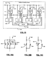
- the current protection module 330 includes a plurality of transistors 330-1, 330-2, 330-3, ..., and 330-N. When current flowing through a respective battery is sufficiently low, the transistors 330 are turned on. When current exceeds a threshold, the transistors 330 are modulated and/or turned off to adjust a resistance R DS provided by each transistor 330. Some of the transistors can be selectively turned on while others are off. While parallel arrangement is shown, a series arrangement can also be used.
- another current protection circuit 340 includes a resistance 342 and a parallel connected switch 344.
- the switch 344 is normally closed. When current through a respective battery increases above a threshold, the switch 344 is opened to increase series resistance by adding the resistance 342. As a result, current flowing through the battery decreases.
- the switch 354 is normally closed. When current through the battery increases above a threshold, the switch is opened to increase series resistance by adding the variable resistance 352. The resistance that is provided may be adjusted by the control module 320. As a result, current flowing through the battery decreases.
- the batteries may be single cell batteries.
- the resistances can be implemented using resistors, transistors or other suitable components.
- the switches may be implemented using transistors or other suitable components.
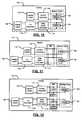
- a medical device such as a pacemaker system 400 is shown.
- the pacemaker system 400 is fully redundant.
- a bad or low battery can be isolated reliably from good or charged batteries.
- a bad or inoperable circuit such as a control module or pulse generator can be reliably isolated from good or operable circuits. Outputs of selected control modules and/or pulse generators can be reliably combined to allow redundancy. As a result, the reliability of the pacemaker system 400 can be improved.
- the pacemaker system 400 includes pulse generators 404A and 404B (collectively, pulse generators 404), switch modules 405-1, 405-2, ..., 405-6 (collectively, switch modules 405) and control modules 408A and 408B (collectively, control modules 404A and 404B).
- pulse generators 404A and 404B collectively, pulse generators 404
- switch modules 405-1, 405-2, ..., 405-6 collectively, switch modules 405
- control modules 408A and 408B collectively, control modules 404A and 404B
- One or more leads 412 connect a selected pulse generator 404 to a patient's heart 414.
- a sealed housing 424 may be used to house components of the medical device.
- the pulse generators 404 and control modules 408 may be integrated into one or more combination modules.
- the switch modules 405, control modules 408, and/or the pulse generators 404 can be combined into one or more integrated circuits.
- a selected one of the control modules 408 controls a first switch module 405-1, which selects an output of one of the pulse generators 404.
- the selected pulse generator 404 is then connected by the switch module 405-1 to the leads 412.
- the pulse generators 404 receive and process signals generated by the patient's heart 414 and selectively deliver heart pacing pulses to the heart 414 as directed by the selected one of the control modules 408.
- a second switch module 405-2 connects one of the switch and protection modules 430-1, 430-2, ... 430-K (collectively, switch and protection modules 430) to one or more of the control modules 408.
- switch modules 405-2 and 405-1 can be actuated to select the other pulse generator 404 or control module 408.
- a power distribution system 420 includes a plurality of batteries 450-1, 450-2, ..., and 450-K (collectively, batteries 450) that can be connected in parallel.
- the power distribution system 420 also includes the switch and protection modules 430.
- Each switch and protection module 430 communicates with one or more of the control modules 408 via the second switch module 405-2 and selectively connects one or more of the batteries 450 to a common voltage rail or node 456.
- the common voltage rail 456 provides power to switch modules 405-3, 405-4, 405-5 and 405-6, which selectively provide power to the pulse generators 404A and 404B and the control modules 408A and 408B, respectively, of the pacemaker system 400.
- the switch and protection modules 430 may sense current flowing from the respective battery 450 and/or voltage across the respective battery 450. This current and/or voltage information is communicated to the control modules 408.
- the control modules 408 direct the switch and protection modules 430 to connect and/or disconnect the respective batteries 450 as needed.
- the control modules 408 may also instruct the switch and protection modules 430 to actively adjust current flow from the batteries 450 using an approach described above in conjunction with FIGs. 16A-16C.
- the control modules 408 may test one of the batteries 450 to ensure sufficient charge prior to switching it onto the common voltage rail 456.
- the control modules 408 may measure, calculate, and store states of charge of each battery.
- the states of charge may be based on open circuit voltage, load testing (e.g., sequentially connecting and measuring high-resistance and low-resistance dummy loads), and/or other suitable approaches.
- the control modules 408 selectively connect respective batteries 450 to the common voltage rail 456 as needed.
- a single battery 450 is connected until its reserve power falls below a threshold.
- the control modules 408 then disconnects the battery 450 and simultaneously connects another battery.
- Capacitive and/or inductive circuits and/or filters may be provided to temporarily power the device during switching to another battery.
- more than one battery 450 can be active at a time, and the control modules 408 may then adjust and/or limit total power and/or total current to a predetermined level.
- the ability to provide additional batteries 450 in the pacemaker system 400 increases the life of the pacemaker system 400.
- the redundancy also improves reliability and increases battery life.
- the pacemaker system 400 may function in a patient for longer periods of time.
- the switch and protection modules 430 provide additional safety when using multiple batteries 450 by limiting excess current.
- the control modules 408A and 408B may be connected together and exchange information. For example, both can be active at all times.
- the watchdog processor may send predetermined data to the active processor and check the returned data to diagnose operability of the active processor. If the active processor does not respond correctly, the watchdog processor and/or another control module may become the active processor.
- an alternate pacemaker system 500 which includes the pulse generator modules 404, the switch modules 405, the control modules 408, the leads 412, a power distribution system 504, and the sealed housing 424 that are arranged in an alternate configuration.
- a first switch module 405-3 selects one of the pulse generators 404.
- the selected pulse generator 404 is connected to the leads 412.
- the pulse generators 404 receive and process signals generated by the patient's heart 414 and selectively deliver impulses to the heart 414 as directed by the control modules 408.
- the control modules 408A and 408B are connected to the switch modules 405, protection modules 520A and 520B (collectively, protection modules 520) and/or the pulse generators 404 as generally shown at "S", “P” and “PG” in FIG. 18.
- the protection modules 520A and 520B are connected by switch modules 405-1, 405-2, 405-4 and 405-5 to the pulse generators 404A and 404B and the control modules 408A and 408B.
- switch modules 405 can be adjusted to select another pulse generator 404 or control module 408.
- the power distribution system 504 includes the plurality of batteries 450 and switch modules 510.
- the batteries 450 are each selectively connected to the first protection module 520A by respective switch modules 510-1A, 510-2A, ..., and 510-KA. Additionally, the batteries 450 are each selectively connected to the second protection module 520B by respective switch modules 510-1B, 510-2B, ..., and 510-KB.
- the protection modules 520 provide power to the pacemaker system 500. Because both protection modules 520 are connected to the selected control module 408, if one protection module 520 fails, the other can be used. If one of the switch modules 510 fails, the other protection module 520 can be used. Furthermore, if for example switch modules 510-1A and 510-2B both fail, both protection modules 520 can be used to allow access to both batteries 450-1 and 450-2.
- the control modules 408 may selectively monitor current flowing through the switch modules 510 and/or protection modules 520 to determine when to selectively connect and/or disconnect batteries 450.
- the control modules 408 may also selectively limit current flowing from the batteries 450 using the protection modules 450, possibly in a manner similar to that described above with respect to FIGs 16A-16C.
- each battery 450 may have a measurement module (not shown) that measures current and/or voltage of the respective battery 450. This information may be transmitted to the control modules 408.
- Each battery 450 may additionally have an associated protection module (individual versions of the protection modules 520) to individually limit its current.
- the control modules 408 in FIG. 18 can also operate in a watchdog processing mode as described above.
- the redundant switch module 510 includes first and second switch modules 511-1 and 511-2 that are connected in series.
- the redundant switch module 510' includes an F by G array of switch modules 560, where F and G are integers greater than one. For example, F and G may both be equal to 2.
- the F switch modules 560-1-x, 560-2-x, ..., and 560-F-x are connected in series with one another. This is true for each x from 1 to G.
- the G sets of F switch modules are connected in parallel with each other. This built-in redundancy increases reliability.
- N switch modules 510 are combined to provide multiple line switch modules 510". While specific examples of the switch modules are shown, the switch modules may include one or more switches connected in any suitable configuration.
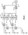
- the pacemaker system 600 which is fully redundant, includes batteries 602-1, 602-2, ..., and 602-C (collectively batteries 602), pulse generators 604-1, 604-2, ..., and 604-D (collectively, pulse generators 604), control modules 608-1, 608-2, ..., and 608-E (collectively, control modules 608), switch modules 610-1, 610-2, ..., and 610-F, and one or more leads 612 connected to a patient's heart 614.
- batteries 602-1, 602-2, ..., and 602-C collectively batteries 602
- pulse generators 604-1, 604-2, ..., and 604-D collectively, pulse generators 604
- control modules 608-1, 608-2, ..., and 608-E collectively, control modules 608-F
- switch modules 610-1, 610-2, ..., and 610-F and one or more leads 612 connected to a patient's heart 614.
- switch modules 610 When one of the batteries 602 fails, another of the batteries 602 can be connected using switch modules 610. When one of the pulse generators 604 or control modules 608 fails, another of the control modules 608 and/or pulse generators 604 can be connected using the switch modules 610. Additional levels of redundancy can be added using additional switch modules 610-1, 610-2, ..., and 610-G as shown in FIG. 21.
- control modules pulse generators, batteries and switch module can be varied depending upon the particular application.
Abstract
Description
- This application is a continuation in part of
U.S. Patent Application Serial No. 11/216,843, filed on August 31, 2005 U.S. Provisional Application No. 60/685,915, filed on May 31, 2005 U.S. Provisional Application No. 60/708,903, filed on August 17, 2005 - The present invention relates to medical devices, and more particularly to power distribution systems for medical devices such as pacemakers.
- Pacemaker systems typically include a controller, a battery, a pulse generator and one or more leads. The pulse generator produces pacing pulses for a heart. The leads deliver the impulses to the heart and sense contractions of the heart. A programming module that is separate from the pacemaker system can be used by the doctor to alter the operation of the pacemaker system after it has been installed in a patient.
- Some pacemaker systems operate on demand. In other words, the pacemaker system stands by until a natural rate of the upper and lower heart falls below a predetermined rate. When this situation occurs, the pacemaker system sends out pacing impulses to ensure that the heart contracts and pumps blood.
- The battery, controller, and pulse generator may be packaged in a sealed housing. The leads typically extend from the sealed housing and have ends that are connected within chambers of the patient's heart. The leads are also typically employed to carry feedback signals from the heart. Using the feedback signals, the controller is able to monitor the heart's activity and trigger the pulse generator appropriately. The battery may be sealed inside of the housing or another component of the pacemaker system. The housing and/or other component is typically removed and the battery is replaced when the stored energy in the battery falls below a threshold. As can be appreciated, replacing the battery requires a patient to undergo additional surgery.
- The leads typically include insulated wires that extend from the pulse generator in the housing through a vein to a heart chamber or chambers. The pacemaker system monitors the heart by sensing electrical signals received by the pulse generator through the leads. The signals that are received provide information relating to contraction of the heart chambers. This information is typically sufficient for the controller to decide when pulses are required.
- Pacemaker systems exist for single chamber and dual chamber applications. A single chamber pacemaker system usually employs a single lead to carry signals to and from one chamber of the heart. Typically, the lead is connected to the right atrium or the right ventricle. This type of pacemaker is often selected for patients having an SA (sinoatrial) node that sends out signals too slowly but whose electrical pathway to the lower heart is in good condition.
- A dual chamber pacemaker usually includes two leads. One lead is located in the right atrium and another lead is located in the right ventricle. This type of pacemaker system can monitor and deliver impulses to either or both of the heart chambers. The dual chamber pacemaker system is typically selected when the SA node signals are too slow and the electrical pathway is partly or completely blocked.
- Adaptive rate pacemakers may also be used. Adaptive rate pacemakers typically include additional sensors that monitor the body's need for blood flow. By monitoring this information, the pacemaker can increase and/or decrease the pace to correct for when the heart's natural rate does not increase sufficiently for an increased level of activity.
- A medical device comprises a pulse generator that selectively generates pulses. A control module selectively controls the pulses. A power distribution system supplies power to the medical device. The power distribution system includes N batteries, where N is an integer greater than one, a common node, and N protection modules that communicate with the control module. The N protection modules selectively connect a respective one of the N batteries to the common node based on control signals from the control module and monitor current provided by the respective one of the N batteries. The control module generates the respective control signals based upon the current.
- In other features, the medical device further comprises first switch modules that selectively connect the common node to the pulse generator and the control module. The medical device comprises a pacemaker system and the pulses include heart pacing pulses. The control module comprises M control modules and the medical device further comprises first switch modules that selectively connect one of the M control modules to the pulse generator, where M is an integer greater than one. The first switch modules also selectively connect the one of the M control modules to one of the N protection modules. The pulse generator comprises P pulse generators and the medical device further comprises second switch modules that selectively connect one of the P pulse generators to the one of the M control modules, where P is an integer greater than one. The medical device further comprises leads and third switch modules that selectively connect the one of the P pulse generators to the leads.
- In other features, the first switch modules comprise redundant switch modules. Each of the N protection modules comprises a current limiting module. The current limiting module comprises X transistors that are connected in parallel, where X is an integer greater than one, and wherein control terminals of the X transistors communicate with the control module. The current limiting module comprises a resistance element and a switch that is connected in parallel with the resistance element and that is selectively controlled by the control module. The resistance element comprises a variable resistance element and the control module selectively varies a resistance of the variable resistance element.
- A medical device comprises pulse generating means for selectively generating pulses. The medical device comprises control means for selectively controlling the pulses and power distribution means. The power distribution means comprises N charge storing means for delivering current, where N is an integer greater than one, a common node, and N protection means for selectively connecting a respective one of the N charge storing means to the common node based on respective control signals from the control means and for monitoring current flowing through the respective one of the N charge storing means. The control means selectively generates the respective control signals based upon the current flowing through the N charge storing means.
- In other features, the medical device further comprises first switching means for selectively connecting the common node to the pulse generator and the control module. The medical device comprises a pacemaker system and the pulses include heart pacing pulses. The control means comprises M control means for adjusting pulses and the medical device further comprises first switching means for selectively connecting one of the M control means to the pulse generating means, where M is an integer greater than one. The first switching means also selectively connects the one of the M control means to one of the N protection means. The pulse generating means comprises P pulse generating means and the medical device further comprises second switching means for selectively connecting one of the P pulse generating means to the one of the M control means, where P is an integer greater than one. The medical device further comprises leads and third switching means for selectively connecting one of the P pulse generating means to the leads.
- In other features, each of the N protection means comprises current limiting means for limiting current. Each of the current limiting means comprises X transistors that are connected in parallel, where X is an integer greater than one, and wherein control terminals of the X transistors communicate with the control means. The current limiting means comprises resistance means for providing resistance and switch means for switching that is connected in parallel with the resistance means and that is selectively controlled by the control means. The resistance means comprises variable resistance means for providing a variable resistance and wherein the control means selectively varies a resistance of the variable resistance means.
- A method for operating a medical device comprises selectively generating pulses using a pulse generator, controlling the pulses using a control module, selectively connecting at least one of a plurality of batteries to a common node, monitoring current flowing through each of the plurality of batteries, and selecting at least one of the plurality of batteries based upon the current flowing through the plurality of batteries.
- In other features, the medical device comprises a pacemaker system and the pulses include heart pacing pulses. The control module includes M control modules and the method further comprises selectively connecting one of the M control modules to the pulse generator, where M is an integer greater than one. The pulse generator includes P pulse generators and the method further comprises selectively connecting one of the P pulse generators to one of the M control modules, where P is an integer greater than one. The one of the P pulse generators is selectively connected to leads. A resistance value of a resistance element connected to one of the plurality of batteries is selectively adjusted to adjust current provided therefrom.
- A medical device comprises P pulse generators that selectively generate pulses for transmission to a patient. A power distribution system comprises N batteries. M control modules selectively control the pulses. L switch modules selectively connect a selected one of the P pulse generators, at least a selected one of the N batteries, and a selected one of the M control modules, wherein P, M, N and L are integers greater than one.
- In other features, the control module monitors current supplied by the N batteries and selectively controls the L switch modules based thereon. N protection modules selectively vary current provided by the at least the selected one of the N batteries. N protection modules selectively limit current provided by the at least the selected one of the N batteries. The L switch modules include first switch modules that selectively connect the N batteries to a common node and second switch modules that selectively connect the common node to the P pulse generators and the M control modules.
- In other features, the medical device comprises a pacemaker system and the pulses include heart pacing pulses. The medical device further comprises leads and third switch modules that selectively connect the selected one of the P pulse generators to the leads. Each of the N protection modules comprise a current limiting module. The current limiting modules comprise X transistors that are connected in parallel, where X is an integer greater than one, and wherein control terminals of the X transistors communicate with at least one of the M control modules. The current limiting module comprises a resistance element and a switch module that is connected in parallel with the resistance element and that is selectively controlled by the control module. The resistance element comprises a variable resistance element and the control module selectively varies a resistance of the variable resistance element.
- A medical device comprises P pulse generating means for selectively generating pulses for transmission to a patient, a power distribution system comprising N current storing means for storing current, M control means for selectively controlling the pulses, and L switch means that selectively connect a selected one of the P pulse generating means, at least a selected one of the N current storing means, and a selected one of the M control means, wherein P, M, N and L are integers greater than one.
- In other features, the control means monitors current supplied by the N current storing means and selectively controls the L switch means based thereon. The medical device further comprises N protection means for selectively varying current provided by the at least the selected one of the N current storing means. The medical device further comprises N protection means for selectively limiting current provided by the at least the selected one of the N current storing means. The L switch means include first switch means for selectively connecting the N current storing means to a common node and second switch means for selectively connecting the common node to the P pulse generating means and the M control means. The medical device comprises a pacemaker system and the pulses include heart pacing pulses. The medical device further comprises leads and third switch means for selectively connecting the selected one of the P pulse generating means to the leads.
- In other features, each of the N protection means comprise a current limiting means for limiting current. The current limiting means comprises X transistors that are connected in parallel, where X is an integer greater than one, and wherein control terminals of the X transistors communicate with at least one of the M control means. The current limiting means comprises resistance means for providing resistance and switch means that is connected in parallel with the resistance means and that is selectively controlled by the control means. The resistance means comprises a variable resistance element and the control means selectively varies a resistance of the variable resistance element.
- A method for operating a medical device comprises selectively generating pulses for transmission to a patient using P pulse generators, distributing power using N batteries, selectively controlling the pulse using M control modules, and selectively connecting a selected one of the P pulse generators, at least a selected one of the N batteries, and a selected one of the M control modules, wherein P, M, N and L are integers greater than one.
- In other features, current supplied by the N batteries is monitored and the L switch modules are selectively controlled based thereon. The current provided by the at least the selected one of the N batteries is selectively varied. The current provided by the at least the selected one of the N batteries is selectively limited. The N batteries are selectively connected to a common node and the common node is selectively connected to the P pulse generators and the M control modules. The medical device comprises a pacemaker system and the pulses include heart pacing pulses. The selected one of the P pulse generators is selectively connected to leads.
- Further areas of applicability of the present invention will become apparent from the detailed description provided hereinafter. It should be understood that the detailed description and specific examples, while indicating the preferred embodiment of the invention, are intended for purposes of illustration only and are not intended to limit the scope of the invention.
- The present invention will become more fully understood from the detailed description and the accompanying drawings, wherein:
- FIG. 1A is a functional block diagram of a laptop computer including a battery pack with batteries that are connected in series according to the prior art;
- FIG. 1 B is a functional block diagram of a plurality of batteries connected in series according to the prior art;
- FIG. 1C is a functional block diagram of a laptop computer including a DC/DC converter and a battery pack according to the prior art;
- FIG. 2A is a schematic diagram of a parallel battery arrangement for a battery pack and laptop computer loads according to the present invention;
- FIG. 2B is a schematic diagram of a parallel battery arrangement for central processing unit (CPU), memory and graphics processing unit (GPU) loads according to one implementation of the present invention;
- FIG. 3A is a functional block diagram of a parallel battery arrangement including battery terminals that are connected in parallel according to the present invention;
- FIG. 3B illustrates the battery of FIG. 3A with a short circuit detecting module;
- FIG. 3C is a functional block diagram of a parallel battery arrangement including battery terminals that are connected in parallel and DC/DC converters according to the present invention;
- FIG. 3D illustrates the arrangement of battery packs having different dimensions in a mobile computing device;
- FIG. 4A is a functional block diagram of a parallel battery arrangement incorporating terminal connecting conductors on a motherboard according to the present invention;
- FIG. 4B is a functional block diagram of a parallel battery arrangement incorporating terminal connecting conductors on a motherboard and DC/DC converters according to the present invention;
- FIG. 5A is a functional block diagram of a parallel battery arrangement incorporating shorting metal stiffeners to ground and power planes on a motherboard according to the present invention;
- FIG. 5B is a functional block diagram of a parallel battery arrangement incorporating shorting metal stiffeners to ground and power planes on a motherboard and DC/DC converters according to the present invention;
- FIG. 6 is a functional block diagram of a parallel battery arrangement that includes a DC/DC converter and a step-up converter according to the present invention;
- FIG. 7 is a functional block diagram of a parallel battery arrangement that includes a DC/DC converter and step-up converter according to the present invention;
- FIG. 8 is a functional block diagram of a parallel battery arrangement that includes a DC/DC converter and a step-up converter according to the present invention;
- FIG. 9 is a functional block diagram of a parallel battery arrangement that includes peripheral devices and a step up converter;
- FIG. 10 is a functional block diagram of a parallel battery arrangement that includes single and two-stage converters according to the present invention;
- FIG. 11 is a functional block diagram of a parallel battery arrangement that includes single and two-stage converters according to the present invention;
- FIG. 12 is a functional block diagram of a parallel battery arrangement that includes single and two-stage converters according to the present invention;
- FIG. 13 is a functional block diagram of an exemplary mobile computing device with loads;
- FIG. 14 illustrates current surge in mismatched batteries according to the prior art;
- FIG. 15 is a functional block diagram of a mobile computing device including a distributed power source and current sense and protection modules according to the present invention;
- FIG. 16A is an exemplary electrical schematic of a current protection module;
- FIG. 16B is an exemplary electrical schematic of another current protection module;
- FIG. 16C is an exemplary electrical schematic of an active current protection module;
- FIG. 17 is a functional block diagram of a power delivery system for medical device such as a pacemaker system;
- FIG. 18 is a functional block diagram of an alternate power delivery system for a medical device such as a pacemaker system;
- FIGs. 19A-19C are functional block diagrams of an exemplary switch modules;
- FIG. 20 is a functional block diagram of an alternate power delivery system for a medical device; and
- FIG. 21 is a functional block diagram of an alternate power delivery system for a medical device.
- The following description of the preferred embodiments is merely exemplary in nature and is in no way intended to limit the invention, its application, or uses. For purposes of clarity, the same reference numbers will be used in the drawings to identify similar elements. As used herein, the term module and/or device refers to an application specific integrated circuit (ASIC), an electronic circuit, a processor (shared, dedicated, or group) and memory that execute one or more software or firmware programs, a combinational logic circuit, and/or other suitable components that provide the described functionality. While the present invention will be described in conjunction with laptop computers and/or laptop loads, the present invention applies to any mobile digital computing device and/or mobile computing device load. As used herein, the term mobile computing device refers to digital devices that include at least one integrated circuit and that are capable of being powered by a mobile power source such as a battery or other portable power storage device. Examples of mobile computing devices include, but are not limited to, laptop computers, MP3 players, personal digital assistants (PDAs), and the like.
- Referring now to FIGs. 1 A, 1 B, and 1C, a mobile computing device according to the prior art, such as a
laptop computer 10, includes one ormore loads 12, such as laptop loads, and abattery pack 14 that powers theloads 12. Thebattery pack 14 includes batteries that are connected in series. Thebattery pack 14 functions as a centralized energy source for the laptop loads 12. In other words, thebattery pack 14 provides current and voltage to the laptop loads 12 throughconductors 16 and/or 18. One of theconductors battery pack 14 includes batteries 20-1, 20-2,..., and 20-X (collectively, batteries 20) that are connected in series, where X is greater than 1. In conventional battery pack designs, thebatteries 20 are connected in series to increase voltage and decrease current. - The
laptop 10 may include a DC/DC converter 22 as shown in FIG. 1C. The DC/DC converter 22 communicates with thebattery pack 14 viaconductors 24 and/or 26. The laptop loads 12 communicate with the DC/DC converter 22 viaconductors 28 and/or 30. One or more of the conductors may be connected to a reference potential such as ground. In this manner, the DC/DC converter 22 receives a first voltage level from thebattery pack 14 and outputs a second voltage level to the laptop loads 12. For example, thebattery pack 14 may output a battery pack voltage such as 12V. The DC/DC converter 22 converts the battery pack voltage to a lower voltage level such as a 1V supply voltage for use by the laptop loads 12. In other words, the DC/DC converter 22 in this example is a step-down converter with a 12:1 conversion ratio. As described above, high conversion ratios tend to have relatively high conversion loss. Increasing the battery pack voltage decreases energy loss associated with parasitic distribution resistance at the expense of increasing loss due to conversion inefficiency. - Referring now to FIG. 2A, a
power distribution system 40 for a mobile computing device according to the present invention includes one or more distributed load centers 42-1, 42-2,..., and 42-M, (referred to collectively as load centers or loads 42). Each of the load centers 42 includes one or more loads. One or more distributed power sources such as batteries 44-1, 44-2,..., and 44-M, (referred to collectively as batteries 44) are connected in parallel with theloads 42. In other words, battery 44-1 is directly connected, and provides power, to the load 42-1. The battery 44-2 is directly connected, and provides power, to the load 42-2. The battery 44-M provides power to the load 42-M. The load centers 42 may include multiple loads. In other words, the number ofbatteries 44 and loads 42 need not be equal. - The parallel distributed arrangement of the
batteries 44 allows power to be distributed to the loads in an optimal manner. For example, typical laptop computer subsystems include loads such as semiconductor loads and other types of loads that are physically dispersed throughout the laptop computer. In the present invention, eachload 42 can receive power from an optimally-locatedbattery 44. In contrast, the loads 12 (as shown in FIGS 1A and 1 C) receive power from a single, centrally-locatedbattery pack 14. - The current requirements of the
loads 42 may be imbalanced. For example, the load 42-1 may require more current than the load 42-2. To prevent uneven power consumption, thepower distribution system 40 in one implementation includes one or moreterminal connections terminal connections batteries 44, respectively. In other words, the first terminal of the first battery is connected to the first terminals of other batteries in the battery pack. A similar approach is used for the second terminals. For example, theterminal connections - Referring now to FIG. 2B, an exemplary
power distribution system 50 includes a central processing unit (CPU)load 52, amemory load 54, and a graphics processing unit (GPU)load 56. TheCPU load 52, thememory load 54, and theGPU load 56 may have different current requirements. Theterminal connections batteries 44. - Referring now to FIG. 3A, a
laptop computer 60 according to a first exemplary implementation of the present invention is shown. Thelaptop computer 60 includesloads 62 andbatteries 64 that are connected in a parallel distribution arrangement. Thebatteries 64 are incorporated in abattery pack 66. Thebatteries 64 provide power to theloads 62 by way of multiple corresponding connections between thebattery pack 66 and theloads 62. Thebatteries 64 are connected (as described in FIGs. 2A and 2B) within thebattery pack 66. - Although the
battery pack 66 is shown located within thelaptop computer 60, those skilled in the art can appreciate that thebattery pack 66 may be located externally to thelaptop computer 60. Further, thelaptop computer 60 may include a plurality of battery packs 66 each including plural batteries connected in parallel as described above. For example, thelaptop computer 60 may include battery packs 66 that are physically located on opposite sides of thelaptop computer 60. - The parallel distribution arrangement of the
loads 62 and thebatteries 64 is advantageous to the manufacture of thebattery pack 66. A battery pack that is connected in series with a load typically includes a plurality of batteries that are connected in series. One or more of the batteries may have a smaller capacity than the other batteries in the battery pack. In this arrangement, a smaller-capacity (i.e. weaker) battery may self-reverse charge when larger-capacity (i.e. stronger) batteries are discharging. As a result, the smaller-capacity battery is damaged, thereby decreasing the overall capacity of the battery pack. Each battery must be charged and discharged to determine actual storage capacities and to avoid including batteries with nonequivalent capacities within a battery pack. - The parallel distribution arrangement of the present invention eliminates manufacturing time and costs that are associated with balancing battery capacity. In a parallel battery pack arrangement, current is naturally distributed from the
battery pack 66 to theloads 62. A stronger battery will provide more current than a weaker battery within the same battery pack, negating the possibility of reverse charging the weaker battery. As a result, the overall battery pack lifetime will increase and the maximum capacity of thebattery pack 66 is used more effectively. For example, one or more of thebatteries 64 may be discharged to a minimum voltage specification to fully exploit the energy of the battery pack and reverse charging will not occur. Similarly, the parallel distribution arrangement provides increased reliability. When one of thebatteries 64 weakens over time, the stronger battery is able to supplement or replace the energy output of the weaker battery. Therefore, the overall capacity of thebattery pack 66 is not significantly reduced. - Referring now to FIG. 3B, the
battery pack 66 may incorporate a shortcircuit detecting module 67 that isolates thebatteries 64 when a short circuit condition is present. In other words, the shortcircuit detecting module 67 monitors the battery pack to determine if the terminals of a battery are shorted and/or if the first terminal of a battery is shorted to the second terminal of another battery. The shortcircuit detecting module 67 may selectively change a position of switches orcontactors 69 to isolate a battery. - The
laptop computer 60 may also include one or more DC/DC converters 70 as shown in FIG. 3C. As described above with respect to FIG. 1C, the DC/DC converters 70 convert the higher voltages of thebatteries 64 to lower voltages suitable for theloads 62. However, due to the parallel distribution arrangement of thelaptop computer 60, the conversion ratio of the DC/DC converters 70 is reduced. For example, the DC/DC converters 70 may have less than a 4:1 conversion ratio. In other implementations, the conversion ratio is less than or equal to 3:1, 2:1 and/pr 1:1. Further, each of the DC/DC converters may have a different conversion ratio. As such, the overall efficiency of thelaptop computer 60 is improved. - Certain semiconductor loads of the
laptop computer 60 may require higher operating frequencies. For example, at an operating frequency of approximately 1 MHz, external passive components may be smaller and less expensive than comparable components operating with low frequency DC/DC converters. In the parallel distribution arrangement, the DC/DC converters 70 may operate at different frequencies. As a result, one of the DC/DC converters 70 may operate at a higher frequency (i.e. between 1 MHz and 4 MHz). - Referring now to FIG 3D, the
laptop computer 60 may include batteries of different sizes in a parallel arrangement to further take advantage of this feature. For example, small form factor laptop computers may maximize available areas for fitting the batteries and/or battery packs 66 each with one or more batteries. In one implementation, thelaptop computer 60 may include a first battery pack 66-1 having a first set of dimensions and/or shape, a second battery pack 66-2 having a second set of dimensions and/or shape, and an nth battery pack 66-N having an nth set of dimensions and/or shape. The battery packs are arranged adjacent to theirprimary loads 62. Each of the battery packs 66 includes one or more batteries. The battery packs 66 are connected together and/or to ground to allow load sharing as described above. - In another implementation, the
laptop computer 60 may include a battery and/or battery pack having an irregular size and/or shape. In still another implementation, thelaptop computer 60 may include multiple mounting positions for batteries and/or battery packs to allow flexible battery pack placement. For example, a first battery pack may be mounted on a top side of thelaptop computer 60 and a second battery pack may be mounted on a bottom side of thelaptop computer 60. Alternatively, a plurality of battery packs may be mounted along an edge of thelaptop computer 60 and/or at corners of thelaptop computer 60. - Referring now to FIGs. 4A and 5A, a
laptop computer 80 includes amotherboard 82. In this implementation, parallel connections between the batteries (as described above) are incorporated on themotherboard 82. For example, the terminal shorting connections may include connectingconductors metal stiffeners 88 that are connected to the PT/P and/or the GT/P of themotherboard 82. Referring now to FIGs. 4B and 5B, thelaptop computer 80 may include one or more DC/DC converters 70 as described in previous implementations. - Referring now to FIGs. 6, 7, and 8, a
laptop computer 90 may also include a step-down DC/DC converter 92 and a step-up DC/DC converter 94. Semiconductor devices in laptop computers may have relatively low voltage requirements. However, certain semiconductor devices may require higher voltages. For example, thelaptop computer 90 may include afirst load 96 and asecond load 98. Thefirst load 96 may require a first voltage, such as 1V. Thesecond load 98 may require a second voltage that is greater than the first voltage, such as 5V. If the batteries provide a battery voltage output that is less than 5V and greater than 1V, step up and step down converters may be used. In the present implementation, the step-up DC/DC converter 94 boosts the voltage of thebattery pack 66 to a voltage suitable for thesecond load 98. - In another implementation, the
laptop computer 100 may include one or more peripheral devices 102 (e.g., a hard disk drive (HDD) or a DVD drive) that have more than one voltage requirement as shown in FIG. 9. For example, theperipheral device 102 may require a first voltage of 5V for a mechanical element such as amotor 104. Theperipheral device 102 may require a second, lower voltage for anotherelectronic element 106. In the present invention, theelectronic element 106 may be able to operate at a range of supply voltages. For example, theelectronic element 106 may operate on power from a single LiOn battery source or a supply voltage of 5V. In conventional systems that operate at 5V in a series arrangement, theelectronic element 106, as well as themechanical element 104, operate at 5V. - However, the
peripheral device 102 may also operate in a parallel distribution arrangement in thelaptop computer 100. In this manner, thelaptop computer 100 includes a step-up DC/DC converter 108 that provides 5V to themechanical element 104. A second step-up DC/DC converter is not required for theelectronic element 106. In other words, theelectronic element 106 is configured to operate at a lower supply voltage as well as operate at 5V, which negates the need for an additional step-up DC/DC converter. - Referring now to FIGs. 10-12, a
laptop computer 110 converts a battery voltage to a 5V supply voltage according to a two-stage DC/DC conversion process. In some implementations, the battery is a Lithium-lon battery, although other types of batteries may be used. Thelaptop computer 110 includes a DC/DC converter 112, a step-down DC/DC converter 114, and a 1:n step-up DC/DC converter 116. The DC/DC converter 112 may be a step-down or step-up converter according to the voltage requirements of theload 118. The DC/DC converter 112 converts the voltage of abattery 120 as described in previous implementations. - The use of a step-up boost converter may be less desirable for certain high current applications. For example, the voltage of the
battery 124 may be between 2.7V and 4.2V. The step-down DC/DC converter 114 first converts the voltage of abattery 124 to a lower voltage. For example, the step-down DC/DC converter 114 converts the voltage of thebattery 124 to 2.5V. The step-up DC/DC converter 116 subsequently converts the lower voltage to a higher voltage suitable for theload 122. For example, the step-up DC/DC converter 116 has a 1:2 conversion ratio and converts the output of the step-down DC/DC converter 114 to 5V. For higher voltage requirements, the step-up DC/DC converter 116 may have a 1:n conversion ratio as necessary. - Those skilled in the art can now appreciate from the foregoing description that the broad teachings of the present invention can be implemented in a variety of forms. The present invention may incorporate other known battery pack and/or power supply configurations in a parallel battery distribution. For example, a power supply or battery pack may implement a parallel battery distribution with universal serial bus (USB) technology according to any of the implementations described herein.
- Referring now to FIG. 13, an exemplary
mobile computing device 200 with loads is shown. Themobile computing device 200 includes a central processing unit (CPU) 204, memory 206 (such as random access memory, read only memory, and/or other suitable electronic storage) and an input/output (I/O)interface 210. Thedevice 200 may further include a graphics processing unit (GPU) 212. Themobile computing device 200 may include one or more peripheral devices such as aDVD drive 214, which includes one ormore motors 218 andcontrol 220. Additional peripheral devices may include a hard disk drive (HDD) 224, which may include one ormore motors 228 and a control module to 230. Thedevice 200 may include anaudio output 232 such as an audio output jack or speaker. The device may include adisplay 234,inputs 236, adisk drive 240 and/or a wireless localarea network interface 242. Theinputs 236 may include audio input, a microphone, a kepypad, buttons, touch pad and/or other inputs. Components of thedevice 200 may be grouped into one or more distributed load centers and supplied in the manner described above. - Referring now to FIG. 14, current surge in mismatched batteries according to the prior art is shown. A
circuit 240 includes afirst battery 244 and asecond battery 248. Thebatteries first battery 244 is a new and/or fully charged battery and thesecond battery 248 is in old, defective and/or fully discharged battery, current flowing to thesecond battery 248 may be too high and cause damage and/or other hazards. - Referring now to FIG. 15, a
mobile computing device 300 includes a distributedpower source 302 and current sense and protection modules according to the present invention. Thedevice 300 includes batteries 304-1, 304-2, 304-3, and 304-4 (collectively batteries 304) that primarily supply loads 306-1, 306-2, 306-3, and 306-4 (collectively loads 306), respectively. Sensing and protection modules 310-1, 310-2, 310-3, and 310-4 (collectively sensing and protection modules 310) are connected to the batteries 304-1, 304-2, 304-3, and 304-4, respectively. The sensing and protection modules 310-1, 310-2, 310-3, and 310-4 sense current flowing through the batteries 304-1, 304-2, 304-3, and 304-4 in any suitable manner and limit current as will be described below. Acontrol module 320 communicates with the sensing and protection modules 310, receives a sensed current signal, and generates one or more control signals to control current flowing through the batteries 304. While four battery/load/sensing and protection module pairs are shown, additional or fewer pairs may be used in a particular implementation. - Referring now to FIG. 16A, a
current protection module 330 is shown. Thecurrent protection module 330 includes a plurality of transistors 330-1, 330-2, 330-3, ..., and 330-N. When current flowing through a respective battery is sufficiently low, thetransistors 330 are turned on. When current exceeds a threshold, thetransistors 330 are modulated and/or turned off to adjust a resistance RDS provided by eachtransistor 330. Some of the transistors can be selectively turned on while others are off. While parallel arrangement is shown, a series arrangement can also be used. - Referring now to FIG. 16B, another
current protection circuit 340 includes aresistance 342 and a parallelconnected switch 344. Theswitch 344 is normally closed. When current through a respective battery increases above a threshold, theswitch 344 is opened to increase series resistance by adding theresistance 342. As a result, current flowing through the battery decreases. - Referring now to FIG. 16C, another current protection circuit 350 shown to include a
variable resistance 352 and a parallelconnected switch 354. Theswitch 354 is normally closed. When current through the battery increases above a threshold, the switch is opened to increase series resistance by adding thevariable resistance 352. The resistance that is provided may be adjusted by thecontrol module 320. As a result, current flowing through the battery decreases. - In some implementations, the batteries may be single cell batteries. The resistances can be implemented using resistors, transistors or other suitable components. The switches may be implemented using transistors or other suitable components.
- Referring now to FIG. 17, a medical device such as a
pacemaker system 400 is shown. Thepacemaker system 400 is fully redundant. In other words, a bad or low battery can be isolated reliably from good or charged batteries. A bad or inoperable circuit such as a control module or pulse generator can be reliably isolated from good or operable circuits. Outputs of selected control modules and/or pulse generators can be reliably combined to allow redundancy. As a result, the reliability of thepacemaker system 400 can be improved. - The
pacemaker system 400 includespulse generators control modules control modules heart 414. A sealedhousing 424 may be used to house components of the medical device. The pulse generators 404 and control modules 408 may be integrated into one or more combination modules. Furthermore, the switch modules 405, control modules 408, and/or the pulse generators 404 can be combined into one or more integrated circuits. - A selected one of the control modules 408 controls a first switch module 405-1, which selects an output of one of the pulse generators 404. The selected pulse generator 404 is then connected by the switch module 405-1 to the
leads 412. The pulse generators 404 receive and process signals generated by the patient'sheart 414 and selectively deliver heart pacing pulses to theheart 414 as directed by the selected one of the control modules 408. - A second switch module 405-2 connects one of the switch and protection modules 430-1, 430-2, ... 430-K (collectively, switch and protection modules 430) to one or more of the control modules 408. When problems are detected with one of the control modules 408 or one of the pulse generators 404, switch modules 405-2 and 405-1, respectively, can be actuated to select the other pulse generator 404 or control module 408.
- A
power distribution system 420 includes a plurality of batteries 450-1, 450-2, ..., and 450-K (collectively, batteries 450) that can be connected in parallel. Thepower distribution system 420 also includes the switch andprotection modules 430. Each switch andprotection module 430 communicates with one or more of the control modules 408 via the second switch module 405-2 and selectively connects one or more of thebatteries 450 to a common voltage rail ornode 456. Thecommon voltage rail 456 provides power to switch modules 405-3, 405-4, 405-5 and 405-6, which selectively provide power to thepulse generators control modules pacemaker system 400. - The switch and
protection modules 430 may sense current flowing from therespective battery 450 and/or voltage across therespective battery 450. This current and/or voltage information is communicated to the control modules 408. The control modules 408 direct the switch andprotection modules 430 to connect and/or disconnect therespective batteries 450 as needed. The control modules 408 may also instruct the switch andprotection modules 430 to actively adjust current flow from thebatteries 450 using an approach described above in conjunction with FIGs. 16A-16C. - The control modules 408 may test one of the
batteries 450 to ensure sufficient charge prior to switching it onto thecommon voltage rail 456. The control modules 408 may measure, calculate, and store states of charge of each battery. The states of charge may be based on open circuit voltage, load testing (e.g., sequentially connecting and measuring high-resistance and low-resistance dummy loads), and/or other suitable approaches. - The control modules 408 selectively connect
respective batteries 450 to thecommon voltage rail 456 as needed. In some implementations, asingle battery 450 is connected until its reserve power falls below a threshold. When the selectedbattery 450 fails to provide sufficient power, the control modules 408 then disconnects thebattery 450 and simultaneously connects another battery. Capacitive and/or inductive circuits and/or filters may be provided to temporarily power the device during switching to another battery. In other implementations, more than onebattery 450 can be active at a time, and the control modules 408 may then adjust and/or limit total power and/or total current to a predetermined level. - The ability to provide
additional batteries 450 in thepacemaker system 400 increases the life of thepacemaker system 400. The redundancy also improves reliability and increases battery life. As a result, thepacemaker system 400 may function in a patient for longer periods of time. The switch andprotection modules 430 provide additional safety when usingmultiple batteries 450 by limiting excess current. Thecontrol modules - Referring now to FIG. 18, an
alternate pacemaker system 500 is shown, which includes the pulse generator modules 404, the switch modules 405, the control modules 408, theleads 412, apower distribution system 504, and the sealedhousing 424 that are arranged in an alternate configuration. A first switch module 405-3 selects one of the pulse generators 404. The selected pulse generator 404 is connected to theleads 412. The pulse generators 404 receive and process signals generated by the patient'sheart 414 and selectively deliver impulses to theheart 414 as directed by the control modules 408. - The
control modules protection modules protection modules pulse generators control modules - The
power distribution system 504 includes the plurality ofbatteries 450 and switchmodules 510. Thebatteries 450 are each selectively connected to thefirst protection module 520A by respective switch modules 510-1A, 510-2A, ..., and 510-KA. Additionally, thebatteries 450 are each selectively connected to thesecond protection module 520B by respective switch modules 510-1B, 510-2B, ..., and 510-KB. - The protection modules 520 provide power to the
pacemaker system 500. Because both protection modules 520 are connected to the selected control module 408, if one protection module 520 fails, the other can be used. If one of theswitch modules 510 fails, the other protection module 520 can be used. Furthermore, if for example switch modules 510-1A and 510-2B both fail, both protection modules 520 can be used to allow access to both batteries 450-1 and 450-2. - The control modules 408 may selectively monitor current flowing through the
switch modules 510 and/or protection modules 520 to determine when to selectively connect and/or disconnectbatteries 450. The control modules 408 may also selectively limit current flowing from thebatteries 450 using theprotection modules 450, possibly in a manner similar to that described above with respect to FIGs 16A-16C. - In another implementation, each
battery 450 may have a measurement module (not shown) that measures current and/or voltage of therespective battery 450. This information may be transmitted to the control modules 408. Eachbattery 450 may additionally have an associated protection module (individual versions of the protection modules 520) to individually limit its current. The control modules 408 in FIG. 18 can also operate in a watchdog processing mode as described above. - Referring now to FIGs. 19A-19C, exemplary
redundant switch modules redundant switch module 510 includes first and second switch modules 511-1 and 511-2 that are connected in series. In FIG. 19B, the redundant switch module 510' includes an F by G array ofswitch modules 560, where F and G are integers greater than one. For example, F and G may both be equal to 2. The F switch modules 560-1-x, 560-2-x, ..., and 560-F-x are connected in series with one another. This is true for each x from 1 to G. The G sets of F switch modules are connected in parallel with each other. This built-in redundancy increases reliability. In FIG. 19C,N switch modules 510 are combined to provide multipleline switch modules 510". While specific examples of the switch modules are shown, the switch modules may include one or more switches connected in any suitable configuration. - Referring now to FIGs. 20 and 21, a medical device such as a
pacemaker system 600 is shown. Thepacemaker system 600, which is fully redundant, includes batteries 602-1, 602-2, ..., and 602-C (collectively batteries 602), pulse generators 604-1, 604-2, ..., and 604-D (collectively, pulse generators 604), control modules 608-1, 608-2, ..., and 608-E (collectively, control modules 608), switch modules 610-1, 610-2, ..., and 610-F, and one or more leads 612 connected to a patient'sheart 614. - When one of the
batteries 602 fails, another of thebatteries 602 can be connected usingswitch modules 610. When one of thepulse generators 604 orcontrol modules 608 fails, another of thecontrol modules 608 and/orpulse generators 604 can be connected using theswitch modules 610. Additional levels of redundancy can be added using additional switch modules 610-1, 610-2, ..., and 610-G as shown in FIG. 21. - As can be appreciated, the number of control modules, pulse generators, batteries and switch module can be varied depending upon the particular application.
- While this invention has been described in connection with particular examples thereof, the true scope of the invention should not be so limited since other modifications will become apparent to the skilled practitioner upon a study of the drawings, the specification and the following claims.
Claims (23)
- A medical device comprising:P pulse generators that selectively generate pulses for transmission to a patient;a power distribution system comprising N batteries;M control modules that selectively control said pulses; andL switch modules that selectively connect a selected one of said P pulse generators, at least a selected one of said N batteries, and a selected one of said M control modules, wherein P, M, N and L are integers greater than one.
- The medical device of Claim 1 wherein said M control modules monitor current supplied by said N batteries and selectively controls said L switch modules based thereon.
- The medical device of Claim 1 further comprising N protection modules that selectively vary current provided by said at least said selected one of said N batteries.
- The medical device of Claim 3 further comprising N protection modules that selectively limit current provided by said at least said selected one of said N batteries.
- The medical device of Claim 1 wherein said L switch modules include first switch modules that selectively connect said N batteries to a common node and second switch modules that selectively connect said common node to said P pulse generators and said M control modules.
- The medical device of Claim 1 wherein said medical device comprises a pacemaker system and said pulses include heart pacing pulses.
- The medical device of Claim 6 further comprising:leads; andthird switch modules that selectively connect said selected one of said P pulse generators to said leads.
- The medical device of Claim 3 wherein each of said N protection modules comprise a current limiting module.
- The medical device of Claim 8 wherein said current limiting modules comprise X transistors that are connected in parallel, where X is an integer greater than one, and wherein control terminals of said X transistors communicate with at least one of said M control modules.
- The medical device of Claim 8 wherein said current limiting module comprises:a resistance element; anda switch module that is connected in parallel with said resistance element and that is selectively controlled by said control module.
- The medical device of Claim 10 wherein said resistance element comprises a variable resistance element and wherein said control module selectively varies a resistance of said variable resistance element.
- A medical device comprising:a pulse generator that selectively generates pulses;a control module that selectively controls said pulses; anda power distribution system that supplies power to said medical device and that comprises:wherein said control module generates said respective control signals based upon said current.N batteries, where N is an integer greater than one;a common node; andN protection modules that communicate with said control module, that selectively connect a respective one of said N batteries to said common node based on control signals from said control module and that monitor current provided by said respective one of said N batteries;
- The medical device of Claim 12 further comprising first switch modules that selectively connect said common node to said pulse generator and said control module.
- The medical device of Claim 12 wherein said medical device comprises a pacemaker system and said pulses include heart pacing pulses.
- The medical device of Claim 12 wherein said control module comprises M control modules and said medical device further comprises first switch modules that selectively connect one of said M control modules to said pulse generator, where M is an integer greater than one.
- The medical device of Claim 15 wherein said first switch modules also selectively connect said one of said M control modules to one of said N protection modules.
- The medical device of Claim 15 wherein said pulse generator comprises P pulse generators and said medical device further comprises second switch modules that selectively connect one of said P pulse generators to said one of said M control modules, where P is an integer greater than one.
- The medical device of Claim 17 further comprising:leads; andthird switch modules that selectively connect said one of said P pulse generators to said leads.
- The medical device of Claim 13 wherein the first switch modules comprise redundant switch modules.
- The medical device of Claim 12 wherein each of said N protection modules comprises a current limiting module.
- The medical device of Claim 9 wherein said current limiting module comprises X transistors that are connected in parallel, where X is an integer greater than one, and wherein control terminals of said X transistors communicate with said control module.
- The medical device of Claim 20 wherein said current limiting module comprises:a resistance element; anda switch that is connected in parallel with said resistance element and that is selectively controlled by said control module.
- The medical device of Claim 22 wherein said resistance element comprises a variable resistance element and wherein said control module selectively varies a resistance of said variable resistance element.
Applications Claiming Priority (4)
| Application Number | Priority Date | Filing Date | Title |
|---|---|---|---|
| US68591505P | 2005-05-31 | 2005-05-31 | |
| US70890305P | 2005-08-17 | 2005-08-17 | |
| US11/216,843 US7610498B2 (en) | 2005-05-31 | 2005-08-31 | Very low voltage power distribution for mobile devices |
| US11/324,450 US7725182B2 (en) | 2005-05-31 | 2006-01-03 | Power distribution system for a medical device |
Publications (2)
| Publication Number | Publication Date |
|---|---|
| EP1728533A1 true EP1728533A1 (en) | 2006-12-06 |
| EP1728533B1 EP1728533B1 (en) | 2009-03-18 |
Family
ID=36940747
Family Applications (1)
| Application Number | Title | Priority Date | Filing Date |
|---|---|---|---|
| EP06009378A Expired - Fee Related EP1728533B1 (en) | 2005-05-31 | 2006-05-05 | Medical device |
Country Status (6)
| Country | Link |
|---|---|
| US (1) | US7725182B2 (en) |
| EP (1) | EP1728533B1 (en) |
| JP (1) | JP5080026B2 (en) |
| DE (1) | DE602006005739D1 (en) |
| SG (1) | SG127816A1 (en) |
| TW (1) | TWI389716B (en) |
Cited By (1)
| Publication number | Priority date | Publication date | Assignee | Title |
|---|---|---|---|---|
| CN103094939A (en) * | 2011-11-01 | 2013-05-08 | 宏碁股份有限公司 | Battery management circuit |
Families Citing this family (18)
| Publication number | Priority date | Publication date | Assignee | Title |
|---|---|---|---|---|
| US8035368B2 (en) * | 2006-02-13 | 2011-10-11 | Freescale Semiconductor, Inc. | Integrated circuit, universal serial bus on-the-go power source and methods for use therewith |
| US7496460B2 (en) * | 2006-09-06 | 2009-02-24 | Eastway Fair Company Limited | Energy source monitoring and control system for power tools |
| US8212412B1 (en) * | 2007-11-30 | 2012-07-03 | Northern Power Systems Utility Scale, Inc. | Energy storage connection system |
| WO2011060096A2 (en) * | 2009-11-11 | 2011-05-19 | Atieva, Inc. | Interlock mechanism for a multiple battery pack |
| EP2468354A3 (en) * | 2010-12-21 | 2012-09-05 | BIOTRONIK SE & Co. KG | Implantable device |
| KR101262524B1 (en) * | 2011-08-04 | 2013-05-08 | 주식회사 엘지화학 | Overcurrent protection apparatus for secondary bettery, protection method and battery pack |
| US10175735B2 (en) | 2011-08-24 | 2019-01-08 | Volcano Corporation | Medical communication hub and associated methods |
| US9543767B2 (en) * | 2012-02-09 | 2017-01-10 | Mitsubishi Electric Corporation | Parallel electricity-storage system and control method thereof |
| EP3424459B1 (en) | 2013-01-16 | 2023-12-13 | Stryker Corporation | Navigation systems for indicating line-of-sight errors |
| US9993273B2 (en) | 2013-01-16 | 2018-06-12 | Mako Surgical Corp. | Bone plate and tracking device using a bone plate for attaching to a patient's anatomy |
| KR102284482B1 (en) * | 2014-12-11 | 2021-08-02 | 삼성에스디아이 주식회사 | battery pack |
| JP6667339B2 (en) * | 2016-03-29 | 2020-03-18 | フクダ電子株式会社 | Intracardiac defibrillation system, connection device in intracardiac defibrillation system, and defibrillator |
| JP6613369B2 (en) * | 2016-04-26 | 2019-11-27 | マクセル株式会社 | Video output system, video output device, and connection cable |
| US10537395B2 (en) | 2016-05-26 | 2020-01-21 | MAKO Surgical Group | Navigation tracker with kinematic connector assembly |
| US10128648B2 (en) * | 2016-06-20 | 2018-11-13 | Lg Chem, Ltd. | Diagnostic system for a DC-DC voltage converter |
| US10177596B2 (en) | 2016-07-08 | 2019-01-08 | Hewlett Packard Enterprise Development Lp | Backup power manager |
| CN110474395A (en) * | 2019-08-27 | 2019-11-19 | 常州格力博有限公司 | Electric system |
| TW202137620A (en) * | 2020-03-25 | 2021-10-01 | 飛宏科技股份有限公司 | Dual port battery charging system for battery pack and the method thereof |
Citations (6)
| Publication number | Priority date | Publication date | Assignee | Title |
|---|---|---|---|---|
| US3866614A (en) * | 1972-04-04 | 1975-02-18 | Siemens Ag | Cardiac actuator |
| US4096866A (en) * | 1976-04-30 | 1978-06-27 | The Johns Hopkins University | Rechargeable body tissue stimulator with back-up battery and pulse generator |
| DE3823922A1 (en) * | 1987-07-15 | 1989-01-26 | Crouzet Sa | ELECTRONIC SWITCHING DEVICE WITH PERFORMANCE MONITORING AND INTEGRATED FUSE FOR ELECTRICAL CIRCUITS |
| US5411537A (en) * | 1993-10-29 | 1995-05-02 | Intermedics, Inc. | Rechargeable biomedical battery powered devices with recharging and control system therefor |
| WO2004025802A1 (en) * | 2002-09-12 | 2004-03-25 | Metallic Power, Inc. | Failure tolerant parallel power source configuration |
| US20040160213A1 (en) * | 2003-02-11 | 2004-08-19 | Stanesti Vlad Popescu | Selector circuit for power management in multiple battery systems |
Family Cites Families (18)
| Publication number | Priority date | Publication date | Assignee | Title |
|---|---|---|---|---|
| US3631860A (en) * | 1969-10-27 | 1972-01-04 | American Optical Corp | Variable rate pacemaker, counter-controlled, variable rate pacer |
| US3748500A (en) * | 1971-12-22 | 1973-07-24 | F Tam | Multiple redundant power supply |
| JP2959657B2 (en) * | 1993-05-13 | 1999-10-06 | キヤノン株式会社 | Electronics |
| JPH0749731A (en) | 1993-08-09 | 1995-02-21 | Toshiba Corp | Portable computer |
| JPH07307696A (en) * | 1994-05-12 | 1995-11-21 | Oki Electric Ind Co Ltd | Portable electronic device |
| US5571141A (en) * | 1994-09-30 | 1996-11-05 | Intermedics, Inc. | Device and method for cardiac arrhythmia therapy with failure detection and backup |
| JP3733554B2 (en) * | 1994-10-31 | 2006-01-11 | 富士通株式会社 | Battery-powered electronic equipment |
| SE519632C2 (en) | 1997-12-23 | 2003-03-25 | Ericsson Telefon Ab L M | Portable electronic device with thin film batteries and their use in the same |
| KR100290988B1 (en) * | 1997-12-29 | 2001-06-01 | 윤종용 | Multi-unit battery pack and device using the same |
| US6223077B1 (en) * | 1998-01-26 | 2001-04-24 | Physio-Control Manufacturing Corporation | Automatic power switching in a defibrillator |
| JP3580123B2 (en) * | 1998-03-20 | 2004-10-20 | 富士通株式会社 | Battery device |
| US6130813A (en) * | 1999-01-11 | 2000-10-10 | Dell U.S.A., L.P. | Protection circuit for electronic devices |
| JP4456194B2 (en) * | 1999-03-02 | 2010-04-28 | 富士通マイクロエレクトロニクス株式会社 | Output circuit and battery pack |
| JP2001298952A (en) | 2000-04-14 | 2001-10-26 | Cosel Co Ltd | Switching power supply unit |
| US6833983B2 (en) * | 2002-02-11 | 2004-12-21 | Intel Corporation | Current limiting super capacitor charger |
| US7791319B2 (en) * | 2003-02-21 | 2010-09-07 | Research In Motion Limited | Circuit and method of operation for an electrical power supply |
| US7209784B2 (en) * | 2003-03-31 | 2007-04-24 | Medtronic, Inc. | High power implantable battery with improved safety and method of manufacture |
| US7560829B2 (en) * | 2004-12-31 | 2009-07-14 | Intel Corporation | Power system using multiple battery pack types |
-
2006
- 2006-01-03 US US11/324,450 patent/US7725182B2/en not_active Expired - Fee Related
- 2006-05-05 DE DE602006005739T patent/DE602006005739D1/en active Active
- 2006-05-05 EP EP06009378A patent/EP1728533B1/en not_active Expired - Fee Related
- 2006-05-16 SG SG200603159A patent/SG127816A1/en unknown
- 2006-05-17 TW TW095117464A patent/TWI389716B/en not_active IP Right Cessation
- 2006-05-24 JP JP2006144471A patent/JP5080026B2/en not_active Expired - Fee Related
Patent Citations (6)
| Publication number | Priority date | Publication date | Assignee | Title |
|---|---|---|---|---|
| US3866614A (en) * | 1972-04-04 | 1975-02-18 | Siemens Ag | Cardiac actuator |
| US4096866A (en) * | 1976-04-30 | 1978-06-27 | The Johns Hopkins University | Rechargeable body tissue stimulator with back-up battery and pulse generator |
| DE3823922A1 (en) * | 1987-07-15 | 1989-01-26 | Crouzet Sa | ELECTRONIC SWITCHING DEVICE WITH PERFORMANCE MONITORING AND INTEGRATED FUSE FOR ELECTRICAL CIRCUITS |
| US5411537A (en) * | 1993-10-29 | 1995-05-02 | Intermedics, Inc. | Rechargeable biomedical battery powered devices with recharging and control system therefor |
| WO2004025802A1 (en) * | 2002-09-12 | 2004-03-25 | Metallic Power, Inc. | Failure tolerant parallel power source configuration |
| US20040160213A1 (en) * | 2003-02-11 | 2004-08-19 | Stanesti Vlad Popescu | Selector circuit for power management in multiple battery systems |
Cited By (1)
| Publication number | Priority date | Publication date | Assignee | Title |
|---|---|---|---|---|
| CN103094939A (en) * | 2011-11-01 | 2013-05-08 | 宏碁股份有限公司 | Battery management circuit |
Also Published As
| Publication number | Publication date |
|---|---|
| EP1728533B1 (en) | 2009-03-18 |
| JP5080026B2 (en) | 2012-11-21 |
| DE602006005739D1 (en) | 2009-04-30 |
| SG127816A1 (en) | 2006-12-29 |
| JP2006334401A (en) | 2006-12-14 |
| US20060267551A1 (en) | 2006-11-30 |
| US7725182B2 (en) | 2010-05-25 |
| TWI389716B (en) | 2013-03-21 |
| TW200700103A (en) | 2007-01-01 |
Similar Documents
| Publication | Publication Date | Title |
|---|---|---|
| EP1728533B1 (en) | Medical device | |
| EP1729203B1 (en) | Power distribution system for mobile computing devices | |
| ES2793924T3 (en) | Method and system for balancing electrical energy storage cells | |
| US20090218984A1 (en) | Battery charger | |
| US20050191528A1 (en) | Battery energy storage module | |
| US20180254641A1 (en) | Dynamic battery cell impedance monitoring | |
| US9077189B2 (en) | Battery protection circuit module device | |
| TWI502851B (en) | Lithium battery module | |
| US20160197496A1 (en) | Energy devices with ultra-capacitor structures and methods thereof | |
| CN101043146B (en) | Apparatus and method for managing power of battery packs in a portable device | |
| EP2990812A1 (en) | Battery monitoring device and battery system using same | |
| KR20200107614A (en) | Electronic device for determining State of Charge of battery device, and operating method of the electronic device | |
| CN106033908B (en) | Power supply circuit, working method thereof and electronic equipment | |
| JP4732897B2 (en) | Power storage device and wiring pattern | |
| EP2130707A2 (en) | Individual-charge and merged-discharge battery set | |
| US20170093184A1 (en) | Method, system and device for power cell management | |
| CN1872360B (en) | Medical device | |
| CN117134440A (en) | Battery protection circuit, battery protection board and electronic equipment | |
| WO2014039424A1 (en) | System and method of power control for a high-availability system | |
| CN110291679B (en) | Battery pack and data transmission method of battery pack | |
| CN116667506B (en) | Discharge circuit, discharge method thereof and electronic equipment | |
| TWI795149B (en) | Power module and power supplying method thereof | |
| CN115379603B (en) | Heating driving circuit, method and electronic equipment | |
| KR102291534B1 (en) | Battery Pack Having Smart Switching Function | |
| CN116470616A (en) | Analog control architecture and wearable electronic equipment |
Legal Events
| Date | Code | Title | Description |
|---|---|---|---|
| PUAI | Public reference made under article 153(3) epc to a published international application that has entered the european phase |
Free format text: ORIGINAL CODE: 0009012 |
|
| AK | Designated contracting states |
Kind code of ref document: A1 Designated state(s): AT BE BG CH CY CZ DE DK EE ES FI FR GB GR HU IE IS IT LI LT LU LV MC NL PL PT RO SE SI SK TR |
|
| AX | Request for extension of the european patent |
Extension state: AL BA HR MK YU |
|
| 17P | Request for examination filed |
Effective date: 20070525 |
|
| 17Q | First examination report despatched |
Effective date: 20070621 |
|
| AKX | Designation fees paid |
Designated state(s): DE FR GB |
|
| GRAP | Despatch of communication of intention to grant a patent |
Free format text: ORIGINAL CODE: EPIDOSNIGR1 |
|
| GRAS | Grant fee paid |
Free format text: ORIGINAL CODE: EPIDOSNIGR3 |
|
| GRAA | (expected) grant |
Free format text: ORIGINAL CODE: 0009210 |
|
| AK | Designated contracting states |
Kind code of ref document: B1 Designated state(s): DE FR GB |
|
| REG | Reference to a national code |
Ref country code: GB Ref legal event code: FG4D |
|
| REF | Corresponds to: |
Ref document number: 602006005739 Country of ref document: DE Date of ref document: 20090430 Kind code of ref document: P |
|
| PLBE | No opposition filed within time limit |
Free format text: ORIGINAL CODE: 0009261 |
|
| STAA | Information on the status of an ep patent application or granted ep patent |
Free format text: STATUS: NO OPPOSITION FILED WITHIN TIME LIMIT |
|
| 26N | No opposition filed |
Effective date: 20091221 |
|
| REG | Reference to a national code |
Ref country code: FR Ref legal event code: PLFP Year of fee payment: 11 |
|
| REG | Reference to a national code |
Ref country code: FR Ref legal event code: PLFP Year of fee payment: 12 |
|
| PGFP | Annual fee paid to national office [announced via postgrant information from national office to epo] |
Ref country code: DE Payment date: 20170530 Year of fee payment: 12 Ref country code: FR Payment date: 20170525 Year of fee payment: 12 Ref country code: GB Payment date: 20170530 Year of fee payment: 12 |
|
| REG | Reference to a national code |
Ref country code: DE Ref legal event code: R119 Ref document number: 602006005739 Country of ref document: DE |
|
| GBPC | Gb: european patent ceased through non-payment of renewal fee |
Effective date: 20180505 |
|
| PG25 | Lapsed in a contracting state [announced via postgrant information from national office to epo] |
Ref country code: DE Free format text: LAPSE BECAUSE OF NON-PAYMENT OF DUE FEES Effective date: 20181201 Ref country code: GB Free format text: LAPSE BECAUSE OF NON-PAYMENT OF DUE FEES Effective date: 20180505 Ref country code: FR Free format text: LAPSE BECAUSE OF NON-PAYMENT OF DUE FEES Effective date: 20180531 |