EP1722670B1 - Body fluid sampling device - Google Patents
Body fluid sampling device Download PDFInfo
- Publication number
- EP1722670B1 EP1722670B1 EP05715716.6A EP05715716A EP1722670B1 EP 1722670 B1 EP1722670 B1 EP 1722670B1 EP 05715716 A EP05715716 A EP 05715716A EP 1722670 B1 EP1722670 B1 EP 1722670B1
- Authority
- EP
- European Patent Office
- Prior art keywords
- fluid
- receiving means
- pathway
- test zone
- fluid pathway
- Prior art date
- Legal status (The legal status is an assumption and is not a legal conclusion. Google has not performed a legal analysis and makes no representation as to the accuracy of the status listed.)
- Active
Links
- 210000001124 body fluid Anatomy 0.000 title claims description 73
- 239000010839 body fluid Substances 0.000 title claims description 73
- 238000005070 sampling Methods 0.000 title claims description 47
- 239000012530 fluid Substances 0.000 claims description 251
- 238000012360 testing method Methods 0.000 claims description 109
- 230000037361 pathway Effects 0.000 claims description 81
- 230000003287 optical effect Effects 0.000 claims description 32
- 238000001514 detection method Methods 0.000 claims description 22
- 239000012491 analyte Substances 0.000 claims description 12
- 230000005291 magnetic effect Effects 0.000 claims description 11
- 238000012546 transfer Methods 0.000 claims description 10
- 238000006243 chemical reaction Methods 0.000 claims description 8
- 238000004458 analytical method Methods 0.000 claims description 7
- 238000011049 filling Methods 0.000 claims description 7
- 230000008859 change Effects 0.000 claims description 6
- 239000002699 waste material Substances 0.000 claims description 5
- 239000011248 coating agent Substances 0.000 claims description 4
- 238000000576 coating method Methods 0.000 claims description 4
- 238000006073 displacement reaction Methods 0.000 claims description 4
- 125000006850 spacer group Chemical group 0.000 claims description 4
- 238000011144 upstream manufacturing Methods 0.000 claims description 4
- 230000000994 depressogenic effect Effects 0.000 claims description 3
- 230000002209 hydrophobic effect Effects 0.000 claims description 3
- 230000008878 coupling Effects 0.000 claims description 2
- 238000010168 coupling process Methods 0.000 claims description 2
- 238000005859 coupling reaction Methods 0.000 claims description 2
- 239000013536 elastomeric material Substances 0.000 claims description 2
- 239000003302 ferromagnetic material Substances 0.000 claims description 2
- 238000001914 filtration Methods 0.000 claims description 2
- 238000002156 mixing Methods 0.000 claims description 2
- 230000005298 paramagnetic effect Effects 0.000 claims description 2
- 239000002907 paramagnetic material Substances 0.000 claims description 2
- 230000026683 transduction Effects 0.000 claims description 2
- 238000010361 transduction Methods 0.000 claims description 2
- 230000008054 signal transmission Effects 0.000 claims 1
- 210000003491 skin Anatomy 0.000 description 71
- 239000008280 blood Substances 0.000 description 33
- 210000004369 blood Anatomy 0.000 description 33
- 238000000034 method Methods 0.000 description 20
- 238000005259 measurement Methods 0.000 description 16
- 239000003153 chemical reaction reagent Substances 0.000 description 14
- 239000000463 material Substances 0.000 description 14
- 230000008569 process Effects 0.000 description 14
- 230000008901 benefit Effects 0.000 description 12
- WQZGKKKJIJFFOK-GASJEMHNSA-N Glucose Natural products OC[C@H]1OC(O)[C@H](O)[C@@H](O)[C@@H]1O WQZGKKKJIJFFOK-GASJEMHNSA-N 0.000 description 11
- 239000008103 glucose Substances 0.000 description 11
- 210000003722 extracellular fluid Anatomy 0.000 description 10
- 239000000758 substrate Substances 0.000 description 10
- 230000032258 transport Effects 0.000 description 9
- 238000009736 wetting Methods 0.000 description 9
- 206010012601 diabetes mellitus Diseases 0.000 description 7
- 238000005530 etching Methods 0.000 description 7
- 239000000835 fiber Substances 0.000 description 7
- 230000001960 triggered effect Effects 0.000 description 7
- 229910052751 metal Inorganic materials 0.000 description 6
- 239000002184 metal Substances 0.000 description 6
- 229920002120 photoresistant polymer Polymers 0.000 description 6
- 230000003247 decreasing effect Effects 0.000 description 5
- 238000013461 design Methods 0.000 description 5
- 238000005286 illumination Methods 0.000 description 5
- 239000007788 liquid Substances 0.000 description 5
- 238000001259 photo etching Methods 0.000 description 5
- XUIMIQQOPSSXEZ-UHFFFAOYSA-N Silicon Chemical compound [Si] XUIMIQQOPSSXEZ-UHFFFAOYSA-N 0.000 description 4
- 229910000831 Steel Inorganic materials 0.000 description 4
- 238000011156 evaluation Methods 0.000 description 4
- 238000004519 manufacturing process Methods 0.000 description 4
- 229910052710 silicon Inorganic materials 0.000 description 4
- 239000010703 silicon Substances 0.000 description 4
- VYPSYNLAJGMNEJ-UHFFFAOYSA-N silicon dioxide Inorganic materials O=[Si]=O VYPSYNLAJGMNEJ-UHFFFAOYSA-N 0.000 description 4
- 239000007787 solid Substances 0.000 description 4
- 239000010959 steel Substances 0.000 description 4
- PNEYBMLMFCGWSK-UHFFFAOYSA-N Alumina Chemical compound [O-2].[O-2].[O-2].[Al+3].[Al+3] PNEYBMLMFCGWSK-UHFFFAOYSA-N 0.000 description 3
- 238000005452 bending Methods 0.000 description 3
- 230000000694 effects Effects 0.000 description 3
- 239000011888 foil Substances 0.000 description 3
- 230000007246 mechanism Effects 0.000 description 3
- 238000012544 monitoring process Methods 0.000 description 3
- 238000003825 pressing Methods 0.000 description 3
- 239000000126 substance Substances 0.000 description 3
- 108090000790 Enzymes Proteins 0.000 description 2
- 102000004190 Enzymes Human genes 0.000 description 2
- GWEVSGVZZGPLCZ-UHFFFAOYSA-N Titan oxide Chemical compound O=[Ti]=O GWEVSGVZZGPLCZ-UHFFFAOYSA-N 0.000 description 2
- 230000009471 action Effects 0.000 description 2
- 238000010241 blood sampling Methods 0.000 description 2
- 238000000835 electrochemical detection Methods 0.000 description 2
- 238000005516 engineering process Methods 0.000 description 2
- 229940088598 enzyme Drugs 0.000 description 2
- 239000004744 fabric Substances 0.000 description 2
- 230000003993 interaction Effects 0.000 description 2
- RBTARNINKXHZNM-UHFFFAOYSA-K iron trichloride Chemical compound Cl[Fe](Cl)Cl RBTARNINKXHZNM-UHFFFAOYSA-K 0.000 description 2
- 150000002739 metals Chemical class 0.000 description 2
- 238000003801 milling Methods 0.000 description 2
- 239000000203 mixture Substances 0.000 description 2
- 239000002245 particle Substances 0.000 description 2
- 238000000206 photolithography Methods 0.000 description 2
- 229920000642 polymer Polymers 0.000 description 2
- 238000007781 pre-processing Methods 0.000 description 2
- 230000005855 radiation Effects 0.000 description 2
- 238000000926 separation method Methods 0.000 description 2
- 239000007858 starting material Substances 0.000 description 2
- 210000001519 tissue Anatomy 0.000 description 2
- 201000004569 Blindness Diseases 0.000 description 1
- 241000237970 Conus <genus> Species 0.000 description 1
- 206010017711 Gangrene Diseases 0.000 description 1
- 108010015776 Glucose oxidase Proteins 0.000 description 1
- 239000004366 Glucose oxidase Substances 0.000 description 1
- 208000013016 Hypoglycemia Diseases 0.000 description 1
- 229910001374 Invar Inorganic materials 0.000 description 1
- 229910021578 Iron(III) chloride Inorganic materials 0.000 description 1
- 206010040576 Shock hypoglycaemic Diseases 0.000 description 1
- 206010052428 Wound Diseases 0.000 description 1
- 238000010521 absorption reaction Methods 0.000 description 1
- 239000004411 aluminium Substances 0.000 description 1
- 229910052782 aluminium Inorganic materials 0.000 description 1
- XAGFODPZIPBFFR-UHFFFAOYSA-N aluminium Chemical compound [Al] XAGFODPZIPBFFR-UHFFFAOYSA-N 0.000 description 1
- 239000007864 aqueous solution Substances 0.000 description 1
- 230000005540 biological transmission Effects 0.000 description 1
- 239000000919 ceramic Substances 0.000 description 1
- 239000000470 constituent Substances 0.000 description 1
- 238000011109 contamination Methods 0.000 description 1
- 210000004207 dermis Anatomy 0.000 description 1
- 238000011161 development Methods 0.000 description 1
- 238000003745 diagnosis Methods 0.000 description 1
- 238000007598 dipping method Methods 0.000 description 1
- 238000009826 distribution Methods 0.000 description 1
- 239000003814 drug Substances 0.000 description 1
- 229940079593 drug Drugs 0.000 description 1
- 238000001035 drying Methods 0.000 description 1
- 239000000975 dye Substances 0.000 description 1
- 235000006694 eating habits Nutrition 0.000 description 1
- 238000006911 enzymatic reaction Methods 0.000 description 1
- 210000000245 forearm Anatomy 0.000 description 1
- 239000011521 glass Substances 0.000 description 1
- 229940116332 glucose oxidase Drugs 0.000 description 1
- 235000019420 glucose oxidase Nutrition 0.000 description 1
- 238000000227 grinding Methods 0.000 description 1
- 230000036541 health Effects 0.000 description 1
- 238000010438 heat treatment Methods 0.000 description 1
- 230000003345 hyperglycaemic effect Effects 0.000 description 1
- 201000001421 hyperglycemia Diseases 0.000 description 1
- 230000002218 hypoglycaemic effect Effects 0.000 description 1
- 230000006872 improvement Effects 0.000 description 1
- 238000010348 incorporation Methods 0.000 description 1
- 230000001678 irradiating effect Effects 0.000 description 1
- 230000007774 longterm Effects 0.000 description 1
- 238000003754 machining Methods 0.000 description 1
- 239000011159 matrix material Substances 0.000 description 1
- 230000005499 meniscus Effects 0.000 description 1
- 238000005459 micromachining Methods 0.000 description 1
- 235000013336 milk Nutrition 0.000 description 1
- 239000008267 milk Substances 0.000 description 1
- 210000004080 milk Anatomy 0.000 description 1
- 239000013307 optical fiber Substances 0.000 description 1
- 230000036961 partial effect Effects 0.000 description 1
- 238000000059 patterning Methods 0.000 description 1
- 230000035515 penetration Effects 0.000 description 1
- 239000004417 polycarbonate Substances 0.000 description 1
- 229920000515 polycarbonate Polymers 0.000 description 1
- 238000011176 pooling Methods 0.000 description 1
- 239000011148 porous material Substances 0.000 description 1
- 238000002203 pretreatment Methods 0.000 description 1
- 239000010453 quartz Substances 0.000 description 1
- 239000002994 raw material Substances 0.000 description 1
- 230000035484 reaction time Effects 0.000 description 1
- 208000037921 secondary disease Diseases 0.000 description 1
- 239000004065 semiconductor Substances 0.000 description 1
- 230000035945 sensitivity Effects 0.000 description 1
- 229910052814 silicon oxide Inorganic materials 0.000 description 1
- 239000002210 silicon-based material Substances 0.000 description 1
- 239000007921 spray Substances 0.000 description 1
- 238000005507 spraying Methods 0.000 description 1
- 238000003860 storage Methods 0.000 description 1
- 230000036962 time dependent Effects 0.000 description 1
- 239000004408 titanium dioxide Substances 0.000 description 1
- 238000007514 turning Methods 0.000 description 1
- 238000003466 welding Methods 0.000 description 1
Images


Classifications
-
- A—HUMAN NECESSITIES
- A61—MEDICAL OR VETERINARY SCIENCE; HYGIENE
- A61B—DIAGNOSIS; SURGERY; IDENTIFICATION
- A61B5/00—Measuring for diagnostic purposes; Identification of persons
- A61B5/145—Measuring characteristics of blood in vivo, e.g. gas concentration, pH value; Measuring characteristics of body fluids or tissues, e.g. interstitial fluid, cerebral tissue
- A61B5/14532—Measuring characteristics of blood in vivo, e.g. gas concentration, pH value; Measuring characteristics of body fluids or tissues, e.g. interstitial fluid, cerebral tissue for measuring glucose, e.g. by tissue impedance measurement
-
- A—HUMAN NECESSITIES
- A61—MEDICAL OR VETERINARY SCIENCE; HYGIENE
- A61B—DIAGNOSIS; SURGERY; IDENTIFICATION
- A61B5/00—Measuring for diagnostic purposes; Identification of persons
- A61B5/14—Devices for taking samples of blood ; Measuring characteristics of blood in vivo, e.g. gas concentration within the blood, pH-value of blood
- A61B5/1405—Devices for taking blood samples
- A61B5/1411—Devices for taking blood samples by percutaneous method, e.g. by lancet
-
- A—HUMAN NECESSITIES
- A61—MEDICAL OR VETERINARY SCIENCE; HYGIENE
- A61B—DIAGNOSIS; SURGERY; IDENTIFICATION
- A61B5/00—Measuring for diagnostic purposes; Identification of persons
- A61B5/15—Devices for taking samples of blood
- A61B5/150007—Details
- A61B5/150015—Source of blood
- A61B5/150022—Source of blood for capillary blood or interstitial fluid
-
- A—HUMAN NECESSITIES
- A61—MEDICAL OR VETERINARY SCIENCE; HYGIENE
- A61B—DIAGNOSIS; SURGERY; IDENTIFICATION
- A61B5/00—Measuring for diagnostic purposes; Identification of persons
- A61B5/15—Devices for taking samples of blood
- A61B5/150007—Details
- A61B5/150206—Construction or design features not otherwise provided for; manufacturing or production; packages; sterilisation of piercing element, piercing device or sampling device
- A61B5/150251—Collection chamber divided into at least two compartments, e.g. for division of samples
-
- A—HUMAN NECESSITIES
- A61—MEDICAL OR VETERINARY SCIENCE; HYGIENE
- A61B—DIAGNOSIS; SURGERY; IDENTIFICATION
- A61B5/00—Measuring for diagnostic purposes; Identification of persons
- A61B5/15—Devices for taking samples of blood
- A61B5/150007—Details
- A61B5/150206—Construction or design features not otherwise provided for; manufacturing or production; packages; sterilisation of piercing element, piercing device or sampling device
- A61B5/150274—Manufacture or production processes or steps for blood sampling devices
- A61B5/150297—Manufacture or production processes or steps for blood sampling devices for piercing devices, i.e. devices ready to be used for lancing or piercing
-
- A—HUMAN NECESSITIES
- A61—MEDICAL OR VETERINARY SCIENCE; HYGIENE
- A61B—DIAGNOSIS; SURGERY; IDENTIFICATION
- A61B5/00—Measuring for diagnostic purposes; Identification of persons
- A61B5/15—Devices for taking samples of blood
- A61B5/150007—Details
- A61B5/150358—Strips for collecting blood, e.g. absorbent
-
- A—HUMAN NECESSITIES
- A61—MEDICAL OR VETERINARY SCIENCE; HYGIENE
- A61B—DIAGNOSIS; SURGERY; IDENTIFICATION
- A61B5/00—Measuring for diagnostic purposes; Identification of persons
- A61B5/15—Devices for taking samples of blood
- A61B5/150007—Details
- A61B5/150374—Details of piercing elements or protective means for preventing accidental injuries by such piercing elements
- A61B5/150381—Design of piercing elements
- A61B5/150412—Pointed piercing elements, e.g. needles, lancets for piercing the skin
- A61B5/150419—Pointed piercing elements, e.g. needles, lancets for piercing the skin comprising means for capillary action
-
- A—HUMAN NECESSITIES
- A61—MEDICAL OR VETERINARY SCIENCE; HYGIENE
- A61B—DIAGNOSIS; SURGERY; IDENTIFICATION
- A61B5/00—Measuring for diagnostic purposes; Identification of persons
- A61B5/15—Devices for taking samples of blood
- A61B5/150007—Details
- A61B5/150374—Details of piercing elements or protective means for preventing accidental injuries by such piercing elements
- A61B5/150381—Design of piercing elements
- A61B5/150412—Pointed piercing elements, e.g. needles, lancets for piercing the skin
- A61B5/150435—Specific design of proximal end
-
- A—HUMAN NECESSITIES
- A61—MEDICAL OR VETERINARY SCIENCE; HYGIENE
- A61B—DIAGNOSIS; SURGERY; IDENTIFICATION
- A61B5/00—Measuring for diagnostic purposes; Identification of persons
- A61B5/15—Devices for taking samples of blood
- A61B5/150007—Details
- A61B5/150374—Details of piercing elements or protective means for preventing accidental injuries by such piercing elements
- A61B5/150381—Design of piercing elements
- A61B5/150503—Single-ended needles
-
- A—HUMAN NECESSITIES
- A61—MEDICAL OR VETERINARY SCIENCE; HYGIENE
- A61B—DIAGNOSIS; SURGERY; IDENTIFICATION
- A61B5/00—Measuring for diagnostic purposes; Identification of persons
- A61B5/145—Measuring characteristics of blood in vivo, e.g. gas concentration, pH value; Measuring characteristics of body fluids or tissues, e.g. interstitial fluid, cerebral tissue
- A61B5/1486—Measuring characteristics of blood in vivo, e.g. gas concentration, pH value; Measuring characteristics of body fluids or tissues, e.g. interstitial fluid, cerebral tissue using enzyme electrodes, e.g. with immobilised oxidase
-
- A—HUMAN NECESSITIES
- A61—MEDICAL OR VETERINARY SCIENCE; HYGIENE
- A61B—DIAGNOSIS; SURGERY; IDENTIFICATION
- A61B5/00—Measuring for diagnostic purposes; Identification of persons
- A61B5/15—Devices for taking samples of blood
- A61B5/151—Devices specially adapted for taking samples of capillary blood, e.g. by lancets, needles or blades
- A61B5/15101—Details
- A61B5/15103—Piercing procedure
- A61B5/15107—Piercing being assisted by a triggering mechanism
-
- A—HUMAN NECESSITIES
- A61—MEDICAL OR VETERINARY SCIENCE; HYGIENE
- A61B—DIAGNOSIS; SURGERY; IDENTIFICATION
- A61B5/00—Measuring for diagnostic purposes; Identification of persons
- A61B5/15—Devices for taking samples of blood
- A61B5/151—Devices specially adapted for taking samples of capillary blood, e.g. by lancets, needles or blades
- A61B5/15101—Details
- A61B5/15115—Driving means for propelling the piercing element to pierce the skin, e.g. comprising mechanisms based on shape memory alloys, magnetism, solenoids, piezoelectric effect, biased elements, resilient elements, vacuum or compressed fluids
- A61B5/15117—Driving means for propelling the piercing element to pierce the skin, e.g. comprising mechanisms based on shape memory alloys, magnetism, solenoids, piezoelectric effect, biased elements, resilient elements, vacuum or compressed fluids comprising biased elements, resilient elements or a spring, e.g. a helical spring, leaf spring, or elastic strap
Definitions
- the present invention relates to the field of body fluid analyses in order to make a diagnosis or to monitor the concentration of analytes such as the blood glucose concentration.
- a body fluid sampling device may comprise a skin piercing element with a fluid pathway for receiving body fluid therein. At least a portion of the fluid pathway is open to the environment.
- the sampling device further comprises a fluid receiving means which is separated from the fluid pathway so that fluid in the pathway will not contact the fluid receiving means in a first (separated) state.
- the device or system can be brought into a second state in which at least a portion of the pathway contacts the fluid receiving means so that fluid is transferred. Based on signals from a sensor of the fluid receiving means analyte concentration can be determined.
- Blood collection and analytical systems are e.g. known from the document EP 0 199 484 which comprise a disposable unit with a capillary to collect body fluid and to transport the body fluid into a detection area.
- EP 0 199 484 which comprise a disposable unit with a capillary to collect body fluid and to transport the body fluid into a detection area.
- the further development of this concept is described in WO 97/42888 .
- the arrangement described in this patent is particularly suitable for collecting relatively small amounts of body fluids which is primarily accomplished by pressing a ring onto the area surrounding a collection site and a pump movement.
- a system for analysis based on small amounts of interstitial fluid is known from EP 0 723 418 .
- a very thin closed hollow needle is inserted into the dermis and interstitial fluid is conveyed through the needle to a test zone by applying pressure to the area surrounding the puncture site.
- a highly miniaturized arrangement which also utilizes a closed needle to withdraw body fluid is known from US 5,801,057 .
- a particular advantage of this arrangement is the extremely thin needle which can be inserted into the arm region of a patient without essentially any pain.
- the prior art sampling and testing devices describe embodiments where sample from a capillary channel is directly transferred to a testing zone which is in contact with the channel. Contrary to that the present invention proposes body fluid sampling and testing devices where the fluid pathway in a phase in which sample is taken up is out of fluidic contact with a testing zone. After having taken up a fluid sample into the fluid pathway at least a portion of the fluid pathway is being contacted with a fluid receiving means that receives fluid from the pathway.
- the fluid receiving means may be a test zone or it may be a zone that transports sample to a test zone. Wetting of the test zone therefore can be initiated in a controlled manner by the contacting step. This triggering of test zone wetting has the advantage that the reaction time (i.e.
- a further advantage compared to the prior art sampling devices is that fluid sampling and contacting of the sampling device with a testing zone can be conducted at different locations. Fluid sampling for example can be done at the front end of a hand-held apparatus while contacting with a testing zone can be made within the apparatus. Due to this shuttle function of the skin piercing element optics or other evaluation means can be moved into the interior of a housing which is advantageous with view to the limited space at the front end.
- a further advantage of contacting the test zone or the fluid receiving means with sample already present in the fluid pathway is that contact can be made with a portion of the fluid pathway that does not contain the first fluid emerging the body. By this influences of plasma and substances from the body surface can be avoided or reduced.
- test zone Furthermore a physical separation of the test zone from blood during the sampling step avoids that test chemistry diffuses into the human body during sampling.
- Document EP 1 371 419 shows an analyte testing device wherein the passage between the testing chamber and the pre-treatment chamber can be sealed. However, the device does not sample body fluids itself. Thus, no contact with a patient takes place.
- the present invention therefore has significant advantages over the fluid sampling devices of the prior art.
- One particular field of application of systems and devices for withdrawing small amounts of body fluid is the so-called spot-monitoring in which the concentration of particular analytes present in body fluids is determined at a particular time. Such measurements can be carried out repeatedly at time intervals in order to monitor a change of analyte concentration.
- spot-monitoring in which the concentration of particular analytes present in body fluids is determined at a particular time. Such measurements can be carried out repeatedly at time intervals in order to monitor a change of analyte concentration.
- Such analysis employing disposable test elements has proven to be particularly advantageous especially in the field of blood sugar measurement by diabetics. If excessively high blood sugar values (hyperglycaemia) occur in a diabetic over a period of time, this can lead to serious long-term damage such as blindness and gangrene.
- a diabetic gets into a state of hypoglycaemia because he has for example injected too large a dose of insuline, this can become life-threatening if the diabetic falls into a so-called hypoglycaemic shock.
- a regular control of the blood sugar level enables the diabetic to avoid hyperglycaemic and hypoglycaemic states and also to learn how to coordinate his eating habits, bodily activity and insuline medication.
- regular blood sugar monitoring also has considerable overall economic advantages since high costs for secondary diseases can be avoided. The reasons which prevent a more widespread and consequent use of blood sugar monitoring are primarily the pain caused by the required body fluid collection and the multiple handling steps of systems currently in the market.
- the diabetic or medical staff must firstly obtain a drop of blood which is usually obtained from the finger pad.
- So-called lancing devices may be used to reduce pain.
- a lancing device must be firstly loaded with a lancet, tensioned, placed on the body surface and triggered. After the lancing process the user has to milk his finger in order to convey a drop of blood out of the puncture wound.
- the diabetic Before this procedure the diabetic has to already place a test strip in a blood sugar measuring instrument and activate it.
- the drop of blood can now be applied to the test strip and after for example 10 seconds a blood sugar measurement is available. Finally the user has to dispose of the spent lancet and test strip.
- the present invention enables the process of blood sugar measurement to be greatly simplified.
- Simplification is reached by employing a piercing element which receives body fluid in a fluid pathway and this fluid then can be automatically contacted with a fluid receiving means including a test zone.
- a simplification of blood glucose testing not only is advantageous for current users, it hopefully also has the effect that more people having diabetes will test their blood glucose concentration on a regular basis.
- a sampling device and system according to the present invention serves to withdraw small amounts of body fluid.
- body fluids are understood in particular as blood, interstitial fluid and mixtures of these body fluids.
- the collection system according to the invention can also be used to withdraw blood from alternate sites on the body such as the forearm and the palm.
- a skin piercing element for withdrawing small amounts of body fluid has a protruding portion with a sharpened end for piercing skin.
- a fluid pathway is located which has a capillary activity to transport body fluid.
- At least a part of the capillary structure, preferably the whole capillary, is open to the outside along its extension.
- a capillary structure is understood within the scope of the invention as a body which transports body fluid as a result of capillary forces towards the proximal end of the capillary structure when the distal area is contacted with body fluid.
- the capillary structure according to the invention is similar to the open needle structures described in US 2003/0018282 and US 2003/0028125 .
- an important difference is that these documents describe microneedles where the capillary channel is steadily in fluidic contact with a test zone so that body fluid received in the capillary channel is directly applied to the test zone and hence initiates reaction.
- the longitudinal extension of the skin piercing element extends from a proximal end which provides a holding area to a distal end having a protruding portion which is intended to be inserted into the skin.
- the hollow needles of the prior art have an opening at their distal end through which body fluid can enter and the fluid pathway then changes into a closed channel or chamber in which the test zone is located.
- the capillary structure according to the present invention preferably is open to the outside over its entire longitudinal extension and the fluid path is not closed by a test zone. Such a structure is also described in EP 1 284 121 .
- Open capillaries can be manufactured by photolithographic methods like those described in the document US 5,801,057 and which are known from the field of semiconductor technology. It is also possible to provide channels, grooves etc. which are open to the outside in solid needles by milling, etching and such like. Such depressions which provide the capillary channel may lead from the tip or at least from a region adjoining the tip of the skin piercing element to a proximal holding region which is connectable to a holding device.
- the depressions or capillaries do not necessarily have to run in straight lines, but can also for example be arranged in spirals, meanders etc.
- the capillaries may be arranged in a network with bifurcations, split capillaries, etc.
- the cross-section of the capillaries can for example be V-shaped, semi-circular or also rectangular.
- PCM photochemical milling
- PCM is the machining of metal structures without heating or mechanically milling the starting material.
- PCM is based on optical pattern transfer and etch processes. It is known to be a micromachining technology.
- the starting materials are metal sheets. There is a wide range of different materials to choose from, ranging from medical steel to aluminium and invar. In the case of steel, most of the standard medical types are available. When compared to silicon, glass or quartz, the cost of the raw material steel is much lower.
- PCM is a Photolithography based fabrication method, i.e. the outline of a structure to be machined is transferred optically.
- a photosensible polymer is applied onto the metal sheet in a film.
- the polymer is referred to as photoresist and comes in two types:
- the photoresist can be selectively removed from the substrate (which is often referred to as patterning).
- aqueous solution e.g. Iron (III) chloride for steel
- the material is selectively removed from the areas where there is no photoresist left (referred to as the "etch").
- the etch step is in its nature generally isotropic, i.e. the etch rate is approximately the same in all directions. Isotropicity can be influenced by a large number of parameters during the photolithography and during the etch, thus it is possible to control the etch profile within certain limits.
- Spray etching offers larger flexibility in controlling etch rates and profiles when compared to dip etching.
- photoresist layer is removed from the substrate to obtain the sampling devices. Removal of photoresist layer is normally a wet process.
- capillary channels In addition to the already mentioned methods for incorporating capillary channels into surfaces, it is also possible to generate the capillary channels by assembling bodies in a way that capillary gaps are created. Thus it is for example possible to fasten two or more solid needles together for example by welding such that the contact areas of the solid needles form capillary channels. In a corresponding manner it is also possible to twist wires together in the form of a stranded wire such that numerous contact areas are formed which generate the capillary channels. Further skin-piercing elements with fluid pathways can be created by applying one or more layer of materials (e.g. laminated foils) onto a flat needle in a way that a capillary gap is created between the layers or is provided in one such layer.
- materials e.g. laminated foils
- the capillary channels which provide the fluid pathway typically have a greater depth than width.
- the ratio of depth to width (generally referred to as aspect ratio) is preferably 0.3 to 3.
- the cross-section of the capillary channel is typically larger than 2500 ⁇ m 2 and less than 1 mm 2 .
- the capillary channel has a width in the range of 50 to 450 micrometers, most preferred around 200 micrometers.
- the capillary channels are open to the outside such that they can take up body fluid while the capillary structure is inserted into the body. In order to achieve a good uptake of body fluid the area of the capillary structure that is open to the outside should have a length of 0.5 mm or more.
- the shape of the skin piercing element is relatively uncritical. It can for example be in the form of a small cube. Special measures are usually not necessary to mount the skin piercing element in a drive unit but a holding region located at the proximal end of the skin piercing element is preferred.
- the holding area is formed integral with the other regions of the skin piercing element.
- Piercing element designs can be employed that are known for disposable lancets of conventional blood sampling systems.
- the holding region can have tapers into which spring elements of a holder of a drive unit engage in order to hold the piercing element.
- the piercing element is advantageously positioned within a holder in such a manner (for example by pressing the end of the piercing element facing away from the tip against a stop) that it allows a good control of the piercing depth.
- the document EP B 0 565 970 refers to such a holder and the interaction between the holder and the disposable lancing unit.
- the body fluid sampling device in addition to the skin piercing element has a fluid receiving means which is spatially separated from the fluid pathway of the skin piercing element so that fluid in that pathway will not contact the fluid receiving means during filling.
- the fluid receiving means and the pathway are contacted to each other after fluid sample has been received in at least a part of the fluid pathway and when start of the analytical reaction is desired.
- the spatial separation of skin piercing element and fluid receiving means enables embodiments where the skin piercing elements is employed as a shuttle to transport sampled fluid to a fluid receiving means.
- This is particularly advantageous when fluid sampling is made in a spatially restricted area (e.g. the front end of apparatus) and the fluid receiving means does not fit well into this limited space.
- the latter in particular is the case for fluid receiving means fixed to a tape as e.g. described in European patent application 1424040 , US 4,218,421 and EP 0 299 517 .
- the shuttle function enables a testing process with the steps of
- a magazine with fluid receiving means When a magazine with fluid receiving means is employed there further can be the steps of exposing a specific fluid receiving means from the stored fluid receiving means to contact the skin piercing element loaded with sample fluid. When the specific fluid receiving means has been evaluated a further fluid receiving means can be exposed to contact sample fluid on a skin piercing element.
- a system according to above shuttle concept therefore has one or more skin piercing elements, a drive for driving a skin piercing element to pierce skin, a transport means to transport the skin piercing means into contact with a fluid receiving means.
- the drive for piercing and the transport means may be employed in the same drive unit.
- the system may comprise a storage unit for multiple fluid receiving means.
- the system further may comprise an exposing unit for successively exposing fluid receiving means to receive fluid.
- the fluid receiving means is a structure that can take up fluid from a fluid pathway of the skin piercing element. This uptake of fluid e.g. can be accomplished by an electrical potential applied between fluid in the fluid pathway and the fluid receiving means.
- the fluid receiving means has a higher capillarity than the fluid pathway of the skin piercing element so that during contact fluid is automatically taken up.
- the fluid receiving means can be made from a fleece or fabric material that has a high capillarity and is hydrophilic (at least in areas for fluid take-up).
- the fluid receiving means may have a particular region which comprises such material of high capillarity or the whole area of the fluid receiving means can act as receiving means for fluid from the fluid channel.
- the fluid receiving means may be a test zone in itself which can be covered with a fabric or woven material or the fluid receiving means may be more complex and allows for pre-processing of sample fluid and /or transport of fluid to a sensor / test zone. Pre-processing may comprise filtration of fluid sample and / or a mixing with reagents.
- the fluid receiving means comprises a test zone with at least one chemistry layer that contains a reagent for detecting an analyte.
- the reagent undergoes a detectable change due to reaction with the analyte to be detected.
- Typical reagents for detecting glucose are based for example on glucose oxidase in conjunction with a chromogenic redox system.
- Reagents are well known in the prior art for optical evaluation which form a colour with glucose from the body fluid.
- reagents are also known from the field of blood sugar test strips which allow electrochemical detection of analytes.
- the reagent mixtures that are used are usually in a solid state and, due to their constituents (e.g. aluminium oxide, kieselguhr and such like), have such a high capillarity that they can take up body fluid from the capillary channel. Since these detection systems are well-known from the prior art they are not described in more detail herein. More information is provided in US 5,762,770 and US 36,268 .
- the body fluid collection system additionally has a drive unit which, when activated, moves the skin piercing element from a first into a second position such that it performs a lancing movement.
- Suitable drive units are well-known from the field of blood sampling systems. It can for example contain a spring which is cocked by the user and when released drives the skin piercing element.
- a particularly advantageous drive unit is described in EP B 0 565 970 .
- Systems / devices for body fluids analysis comprise a detection unit. If a sensor / test zone containing reagent is used which changes colour or forms a colour when an analyte is present, the system can have an optical detection unit comprising a light source and a detector to detect transmitted or reflected light. When electrochemical detection is employed, the system has electrodes which contact the test zone or the fluid receiving means. For evaluation of raw signals the system can have electronic devices known in the prior art in order to determine the concentration of analyte for example by measuring the so-called Cotrell current (see e. g. US 36,268 ).
- body fluid can be withdrawn while the protruding portion is inserted into the skin (i.e. withdrawal of sample directly from the body and / or from body fluid emerging on the body surface) or the protruding portion can be retracted from the body after piercing and takes up body fluid that emerges on the body surface.
- a partial withdrawal in which the protruding portion remains in the body but the lancing channel in the skin is opened to collect body fluid is especially suitable for sampling at the arm. This is due to the fact that small incisions on the arm close very rapidly such that no fluid or only very small amounts of fluid emerge after piercing.
- the sensitivity to pain is much less pronounced on the arm as compared for example to the finger and thus when the protruding portion remains in the body this is not felt to be painful.
- an advantage of a capillary structure that is open to the outside is that fluid can be taken up through the open fluid channel whereas the area for taking up liquids by hollow needles is limited to the front end of the needle.
- the latter is particularly disadvantageous when the needle opening becomes sealed by tissue (due to a stamped out tissue portion) during the piercing process such that no liquid or only an inadequate amount can be taken up.
- a withdrawal process can be carried out with the sampling device according to the invention which is a combination of the previously mentioned processes.
- piercing is carried out firstly, the protruding portion is pulled back over a part of the piercing path and is allowed to reside there for a collection period of few seconds.
- An advantage of this process is that the retraction of the protruding portion exposes a part of the lancing channel such that body fluid collects therein and can enter from there into the fluid pathway of the skin piercing element.
- Further such withdrawal process has the advantage that blood on the skin surface can be taken up by the open channel. Depending on the circumstances it may even be possible to remove residual blood almost completely so that no blood is seen by the user.
- a further decisive factor which is important for an efficient uptake of body fluid into the fluid pathway is the wettability of the capillary channel.
- capillary structures made of silicon these are usually adequately wettable due to a silicon oxide layer on the surface. If metals are used for the capillary structure, these are often relatively difficult to wet. This can be counteracted by a number of different measures such as silication of the surface.
- the wettability is usually adequate when the liquid in the capillaries has a concave meniscus which is the case when the wetting angle is less than 90°.
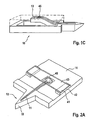
- Figure 1 shows a skin piercing element (10) which has a fluid pathway (11) which runs in an elongated portion (12,13) of the skin piercing element.
- This portion is connected to a holder (14) in form of a frame.
- the elongated portion has a protruding portion (12) which protrudes from the holder portion (14).
- a sharpened tip (15) is located at the front end of the protruding portion.
- the sharpened tip (15) enables penetration of the skin surface during pricking with the skin piercing element.
- the fluid pathway (11) starts in the front end region of the protruding portion and extends into a movable portion (13) which is located in the holder frame (14).
- the fluid pathway is an open capillary channel which permits body fluid which contacts the channel in the region of the protruding portion to move into the moveable portion (13) by means of capillary action.
- moveable portion and frame portion of the skin piercing element are formed integrally.
- the skin piercing element (10) can be made by etching processes. As well known in silicon manufacturing processes a wafer of silicon material can be etched to provide devices comprising tips and capillary channels. For mass production it is however advantageous to produce the skin piercing elements by etching of thin metal plates. It is particularly advantageous that the sharpened tip (15) of the protruding portion (12) can be formed during the etching process as well so as to avoid separate grinding steps.
- Figure 1B shows the skin piercing element (10) of figure 1A together with a fluid receiving means including a test zone.
- the fluid receiving means (40) is shown schematically.
- the fluid receiving means (40) is located on the upper side of the skin piercing element on which side the fluid channel (11) is open to the environment.
- the fluid receiving means (40) is, however, initially spaced from the fluid pathway (11) so that sample fluid within the fluid pathway does not contact the fluid receiving means. Therefore no fluid transfer from the fluid pathway onto the fluid receiving means occurs in this geometry of the fluid sampling device.
- the fluid receiving means essentially consists of a holding structure (41) which provides proper orientation and spacing of the fluid receiving means relative to the skin piercing element and a test zone (45).
- the test zone is a reagent chemistry which produces an optical signal based on the concentration of analyte in the body fluid. Due to the incorporation of porous materials as e.g. kieselguhr or titanium dioxide the reagent chemistry already has high capillarity that sucks fluid from capillary channel (11). The reagent chemistry is applied to a carrier surface. As shown in figure 1B initially the fluid pathway and the test zone (45) are spaced apart so that body fluid located in the capillary channel (11) will not be transferred to the test zone (45). After fluid has been received in the fluid pathway and has filled the moveable section (13) the body fluid sampling device is primed for measurement.
- porous materials e.g. kieselguhr or titanium dioxide
- the moveable section (13) can be bend in direction of the sensor (45) so that body fluid located in the fluid pathway contacts the test zone and wettes the reagent chemistry.
- This mode of contacting the sensor with sample fluid has several advantages over the prior art devices.
- a first advantage over the prior art is that measurement can be initiated at a specific point in time. This means that the time between wetting of the test zone and measurement of the final signal can be chosen at will. The time period, however, is shorter than the drying time of blood in the capillary. Knowing or controlling the time of reaction improves accuracy of the measurement. Further a signal can be measured beginning directly after wetting which allows to monitor reaction kinetics. Evaluation of this early signals can be used to improve accuracy of the measurement result as well.
- a further advantage can be seen from figure 1B . When the moveable section (13) is contacted with the test zone (45) it contacts an intermediate section of the fluid channel (11) but not the very end.
- the intermediate portion of the channel therefore contains fluid almost uncontaminated and without ISF. Since fluid from this region is transferred to the fluid receiving means and therefore needs to be accessible, this region is called the access region.
- This concept of transporting fluid from the capillary to the fluid receiving means serves to exclude disturbances of measurement by plasma or substances from the skin surface. It goes by its own that contamination by substances from the skin surface should be avoided if possible, in particular, when the amounts of sample for analysis are decreased to low amounts (e.g. below 1 microliter).
- this body fluid normally does not show the actual blood glucose concentration but a concentration from 5 to 30 minutes before. This is due to the time delay of exchange between the blood compartment and the interstitial fluid compartment.
- FIG 1C shows the moveable portion due to its shape in form of a tongue can be bent upwardly.
- the moveable section automatically will have enough flexibility if the skin piercing element is made from a ductile material. Suitable materials are e. g. metals, silicon and even ceramics which do not brake upon bending.
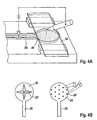
- Figure 2 shows a second embodiment where contact between the fluid channel and the fluid receiving means is accomplished by a moveable fluid receiving means.
- the skin piercing element has a protruding portion (12) with a tip (15) for piercing the skin.
- a fluid channel (11) in form of a capillary channel starts close to the piercing tip (15) and extends into an intermediate section of the holder portion (14).
- the fluid receiving means comprises a spacer (42) and a moveable carrier (43) fixed to the spacer.
- the moveable carrier (43) at its underside holds a test zone (45) in form of a reagent matrix for optical detection.
- the moveable carrier (43) When the capillary channel (11) is filled with sample fluid the moveable carrier (43) is depressed and the test zone (45) contacts the filled channel and takes up body fluid.
- the transparent carrier (43) now can be illuminated and radiation reflected by the back side of the test zone (45) can be measured to obtain a signal.
- Figure 2B shows the portion of the fluid channel (11) which contacts the sensor (45) in more detail.
- the channel has upstanding walls which protrude from the upper surface of the skin piercing element (14).
- the upstanding walls (11') have pointed edges. The function of these edges can better be seen in figure 2C which shows the interaction between test zone and fluid pathway (11).
- the left drawing of figure 2C shows the test zone (45) approaching the fluid pathway.
- the test zone (45) is located at the underside of a carrier (40).
- the body fluid (25) residing in the fluid pathway (11) has a depressed conus. This means that a slight contact between the test zone and the walls of the fluid pathway may not be sufficient to contact the body fluid with the testing material.
- Figure 3 depicts four embodiments showing cuts through piercing elements and test zones. This will illustrate a technical problem which has to be accounted for.
- a hydrophobic coating (16) has been applied on the body piercing element beside the fluid channel.
- contact of the test zone with the skin piercing element does not only bring the test zone and body fluid into contact but during the contact capillary spaces are generated between the test zone (or the carrier) on one hand and the portions beside the fluid pathway on the other hand.
- This normally creates a high capillarity which transfers sample fluid residing in the channel not only on the test zone but also into the small capillary spaces which are generated.
- the hydrophobic coating (16) avoids sample fluid from creeping between the upper surface of the skin piercing element (14) and the carrier or test zone. It is desired to transfer the sample onto a dedicated area of the testing material so that the transferred amounts of sample fluid are sufficient to wet the test zone in a way that an accurate measurement can be achieved. Loosing sample fluid to other regions of the test zone or to the carrier could mean that the testing material is not wetted sufficiently in the dedicated region and measurement cannot not be conducted properly.
- Figure 3B shows a further embodiment which avoids an unintentional creeping of sample fluid. Similary to figure 2 this embodiment has upstanding channel walls which contact the test zone or carrier. Due to this, fluid that creeps into spaces stops at the outer channel walls and a loss of sample fluid is largely reduced.
- the channel walls do not need to be square shaped as depicted in figure 3B but they may also be pointed as shown in figure 3C or 3D .
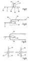
- Figure 4 shows the concept of electrical triggering a contact of sample fluid with the test zone.
- This general concept is shown in figure 4 with respect to a skin piercing element as special embodiment of a support structure having a channel.
- a skin piercing element for fluid triggering a high potential is applied between the sample fluid (25) and the carrier (40). This causes a movement of the carrier in direction of the channel. Wetting of the test zone by sample fluid can be triggered in a very short time frame by turning on the electrical potential.
- the channel beneath the test zone leads into a collecting zone (26) for providing a larger amount of fluid for wetting the test zone than the thin capillary channel would provide.
- FIG. 4B depicts preferred embodiments of collecting zones in more detail.
- the collecting zone (26) preferably has upstanding elements (26') which facilitate movement of fluid onto the test zone.
- These upstanding elements on one hand provoke high electrical charges at their end for transporting fluid and on the other hand they improve capillarity of the collecting zone (26) which improves filling with fluid.
- Figures 5A , B and C depict sampler designs for providing skin piercing element and test zone in a spaced apart geometry that allows contacting of test zone with sample fluid in the channel by actuation.
- the embodiment of figure 5A is similar to Figure 1 .
- the skin piercing element comprises a frame which is connected to an inner portion (13') in which runs the capillary channel (11). Inner portion and frame are connected by bendable portions (51). After filling of the capillary channel the inner portion is torsioned against the frame so that a portion of the capillary contacts the test zone beneath the carrier (43). By bending around the bendable portions the inner portion contacts the test zone in an angled manner. This has proven to be particularly advantageous since it provides a uniform wetting of the test zone without inclusion of air bubbles.
- Figure 5B shows an embodiment where the carrier (43) and its support are connected via bendable portions (51') to a main portion (14') which comprises the capillary. Again contact between capillary and test zone is accomplished in a tilted manner.
- Figure 5C shows an embodiment having an inner portion (13 ") which is connected at two ends to the frame portion (14"). When pressure is applied from the underside to the central part of the inner portion (13") this bends against the test zone beneath the carrier (43). By bowing this inner portion again an angled contacting is achieved.
- Figure 6 schematically depicts an improved shape of the capillary channel. It has been found that the fill level of fluid in the channel generally increases with decreasing width of the capillary.
- the capillary of figure 6 has a first region (a) which leads into the tip portion of the skin piercing element.
- a second region (b) of increased diameter is for providing an increased sample volume.
- Particularly useful is third region (c) of decreased width. Due to the decreased width the fill level is increased and therefore transfer of fluid from the channel to the test zone has a high success rate. Therefore it is preferred to contact the test zone with the capillary in a tilted manner so that it first contact region (c) and thereafter region (b). This ensures that fluid transfer will be initiated safely by region (c) and enough sample for testing is provided by region (b).
- Region (d) downstream region (c) may be employed to discharge contaminated sample fluid or ISF.
- Figure 7 shows a skin piercing element having a first region (a) leading into the tip region and a second region (b) of increased diameter.
- Picture A shows a status after skin has been pierced and blood was taken into region (a) of the capillary channel. Due to lower decreased capillarity of region (b) sample liquid fills region (a) but not region (b).
- the skin piercing element is contacted with a carrier (43) the open channel structure (a, b, d) in some portion is closed at its top and capillarity is hence increased in this portion so that collection region (b) is filled and a test zone on the underside of the carrier (43) gets into contact with sample fluid. It is advantageous to have a circular detection area with view to the geometry of optical elements.
- a skin piercing element according to figure 7 may be used in following exemplary method:
- Figure 8 shows a concept where the contact between the sensor 45 and fluid pathway or channel 11 can be established by employing magnetic forces 70.
- a paramagnetic or ferromagnetic material 72 is incorporated, deposited or attached to the sensor, or to the channel portion 13.
- a current carrying wire of appropriate geometry is incorporated or attached to the sensor or the channel portion.
- a magnetic field 72 provided by an electromagnet 74 (or permanent magnet, solenoid, or other suitable means) thus exerts an actuation force 70 on the sensor (or channel portion or both), bringing them into fluidic contact.
- the force magnitude and thus the time-dependent triggering of the fluidic contact is controlled by controlling the magnetic field strength, i.e. by switching the electro magnet 74 or approaching a permanent magnet.
- a magnetic dipole moment may be induced in a nonmagnetic ring (or similar geometry) deposited on the sensor or channel portion by time-varying magnetic fields at the location of the ring. This represents an alternative way to produce an actuation force for triggered fluidic contact.
- an optical index matching element 80 is employed for coupling the test zone (sensor 45) of the fluid receiving means 82 to an optical detection unit (not shown), and, at the same time, for exerting a mechanical force to bring the fluid pathway 11 and the sensor 45 of the fluid receiving means 82 into a contacting state.
- the glucose concentration is determined by a kinetic measurement of the colour change in the sensor 45 upon wetting with a sufficiently large amount of blood contained in the pathway or channel 11.
- a reflectometric measurement is performed by illuminating the sensor 45 with incident light 84 of appropriate wavelengths and detection of the reflected radiation 86.
- the limited detection area on the sensor 45 imposes severe constraints on the mechanical positioning tolerances of the wetted test zone with regard to the optical detection system. Furthermore, if only a small detection area is available, inhomogeneities in the sensor enzyme chemistry more severely influence the coefficient of variation for repeated glucose measurements. Simultaneous optical detection of the triggered actuation between blood and sensor 45 necessitates that there no interference between the triggering actuation mechanism and the optical detection system.
- An optical system consisting of appropriate light emitter and receiver and and optics such as lenses and/or optical fibres is employed for the reflectomertric measurement.
- the amount of light of a certain wavelength reflected from the sensor 45 gives a measure of the glucose concentration.
- the sensor 45 typically consists of an enzyme chemistry mixed with small particles providing diffuse reflection of the incoming light, deposited on a polycarbonate strip or foil 82 with well defined optical transmission properties.
- the irradiating light 84 is diffusely scattered by the particles in the strip, and absorbed by dyes activated by enzymatic reactions with blood glucose.
- the amount of reflected light 86 is reduced by increased absorption with increasing glucose concentration.
- the elastomeric optical element 80 has a refractive index closely matched to that of the sensor 45.
- the element 80 is employed as an intermediate layer or slab between the sensor 45 and the optics of the detection unit.
- the element 80 may have a means 88 which allow it to be used as a lever arm for the transduction of mechanical displacement for the triggered actuation of the sensor 45 (see Figure 9 ).
- the sensor 45 on its one side abuts the element 80, whereas the opposite site of the sensor is separated by means of spacers 90 form the channel 11, keeping free an air gap 92.
- the fluid receiving means 82 Upon actuation, the fluid receiving means 82 is bend downwards and blood in the micro channel 11 underneath the sensor 42 is transferred onto the sensor, and the kinetic colour change reaction takes place.
- an optical waveguide/fibre assembly 94 in conjunction with the intermediate matching element 80 is used to illuminate the sensor 45 and collect reflected light, while the waveguide/fibre 94 simultaneously serves to displace the element 80 and hence the sensor 45 against the fluid pathway or channel 11.
- the optical waveguide/fibre 90 may also directly actuate the sensor 45, if the index matching element is provided by a special coating.
- the optical waveguide/fibre bundle 94 is mechanically actuated by an actuation mechanism (a motor, or other drive unit, or a mechanism translating the microsampler movement into a displacement of the optical waveguide/fibre).
- the intermediate elastomeric material 80 translates the mechanical displacement of the optical fibre or other mechanical actuator directly to the sensor 45, thereby serving as a mediator for the triggered actuation/contact between the sensor 45 and the adjacent portion of the blood-filled micro fluidic channel 11.
- the bundle 94 of small diameter fibres 96 is furthermore used to address small regions on the sensor 45, since the cone of acceptance of light for each single fibre 96 in the bundle is limited by its numerical aperture.
- a densely packed bundle of fibres thus serves to sample discrete small regions on the sensor.
- a few of the fibres may actually sample parts of the wetted detection area on the sensor, while other fibres sample the non-wetted parts.
- the bundle of fibres may be coupled to a detector array or CCD for individual readout of the fibres, thus generating an image of the detection area. Individual sampling of the fibres enables the detection in a small sensor area, while mechanical positioning tolerances are largely relaxed.
- Each single fibre may either be addressed for illumination of the sensor, or for collection of the diffuse reflected light, or for simultaneous illumination and collection if an appropriate beam splitter is used.
- a randomized distribution of the fibres in the bundle is desirable to provide homogeneous illumination of the sensor and complete detection coverage of the sensor surface.
- Fig. 11 shows an example for a body fluid sampling device wherein the laterally open capillary channel 11 has a sampling section 100 and a discharge section 102 branching off upstream the sampling section for taking up a fraction of the body fluid entering the capillary first at the tip region 104.
- This again allows for discharge of contaminated sample fluid or ISF, as explained above in connection to Fig. 6 .
- the capillarity of discharge section 102 is higher than the capillarity of the inlet section 106 in the region of the branching 108.
- the discharge section 102 may be closed by a lid 110. In this case, it is important to leave open a vent 112 at the end of the discharge section.
- Fig. 12 depicts an embodiment in which the discharge section is extended to comprise a waste region 114 and a reservoir region 116 upstream the waste region.
- the sampling or target section 100 is not filled during an uptake phase due to the wide opening. Only in the contact phase where the sensor 118 is brought into contact with the sampling section 100 and closes this region as a lid, the capillarity is increased and blood is sucked out of the reservoir region 116 into the sampling section 100.
- the volume of the discharge section is sufficiently large in order to be able to fill the sampling section 100 and additionally to take up the waste fluid.
- multiple discharge sections 102 can be employed.
- Different intersecting configurations 120 can be used in order to direct the fluid under capillary action ( Fig. 14 ).
Description
- The present invention relates to the field of body fluid analyses in order to make a diagnosis or to monitor the concentration of analytes such as the blood glucose concentration.
- The invention concerns a device or system for sampling small amounts of body fluid. A body fluid sampling device may comprise a skin piercing element with a fluid pathway for receiving body fluid therein. At least a portion of the fluid pathway is open to the environment. The sampling device further comprises a fluid receiving means which is separated from the fluid pathway so that fluid in the pathway will not contact the fluid receiving means in a first (separated) state. The device or system can be brought into a second state in which at least a portion of the pathway contacts the fluid receiving means so that fluid is transferred. Based on signals from a sensor of the fluid receiving means analyte concentration can be determined.
- Systems for sampling body fluids are already known in the prior art in which body fluid is taken up into a disposable element. Blood collection and analytical systems are e.g. known from the document
EP 0 199 484 which comprise a disposable unit with a capillary to collect body fluid and to transport the body fluid into a detection area. The further development of this concept is described inWO 97/42888 EP 0 723 418 . For this purpose a very thin closed hollow needle is inserted into the dermis and interstitial fluid is conveyed through the needle to a test zone by applying pressure to the area surrounding the puncture site. A highly miniaturized arrangement which also utilizes a closed needle to withdraw body fluid is known fromUS 5,801,057 . A particular advantage of this arrangement is the extremely thin needle which can be inserted into the arm region of a patient without essentially any pain. - Whereas the arrangement described in
US 5,801,057 already fulfils numerous practical requirements, some features are in need of improvement. A general problem with the sampling devices according to the previously mentioned document is to manufacture the hollow needle cost-effectively and as small as possible. - With this aim body fluid samplers which have an open fluid pathway structure are contemplated. The documents
US 2003/0018282 andUS 2003/0028125 both describe skin piercing devices which have an open channel for body fluid sampling which at least partially is located in a region of a piercing needle. Body fluid sampled into the fluid pathway is transferred to a testing zone which is fixed to the skin piercing element. In particularUS 2003/0028125 describes that the skin piercing element is integral with a part of a test strip. A further document that contemplates a similar sampling and testing device with provision of a pooling area is described inUS 2002/0168290 . - The prior art sampling and testing devices describe embodiments where sample from a capillary channel is directly transferred to a testing zone which is in contact with the channel. Contrary to that the present invention proposes body fluid sampling and testing devices where the fluid pathway in a phase in which sample is taken up is out of fluidic contact with a testing zone. After having taken up a fluid sample into the fluid pathway at least a portion of the fluid pathway is being contacted with a fluid receiving means that receives fluid from the pathway. The fluid receiving means may be a test zone or it may be a zone that transports sample to a test zone. Wetting of the test zone therefore can be initiated in a controlled manner by the contacting step. This triggering of test zone wetting has the advantage that the reaction time (i.e. the time between contacting a test chemistry with sample fluid and reading of test results) can be controlled which leads to higher accuracy of analyte determination. A further advantage compared to the prior art sampling devices is that fluid sampling and contacting of the sampling device with a testing zone can be conducted at different locations. Fluid sampling for example can be done at the front end of a hand-held apparatus while contacting with a testing zone can be made within the apparatus. Due to this shuttle function of the skin piercing element optics or other evaluation means can be moved into the interior of a housing which is advantageous with view to the limited space at the front end. A further advantage of contacting the test zone or the fluid receiving means with sample already present in the fluid pathway is that contact can be made with a portion of the fluid pathway that does not contain the first fluid emerging the body. By this influences of plasma and substances from the body surface can be avoided or reduced.
- Furthermore a physical separation of the test zone from blood during the sampling step avoids that test chemistry diffuses into the human body during sampling.
- Document
EP 1 371 419 shows an analyte testing device wherein the passage between the testing chamber and the pre-treatment chamber can be sealed. However, the device does not sample body fluids itself. Thus, no contact with a patient takes place. - The present invention therefore has significant advantages over the fluid sampling devices of the prior art.
- One particular field of application of systems and devices for withdrawing small amounts of body fluid is the so-called spot-monitoring in which the concentration of particular analytes present in body fluids is determined at a particular time. Such measurements can be carried out repeatedly at time intervals in order to monitor a change of analyte concentration. Such analysis employing disposable test elements has proven to be particularly advantageous especially in the field of blood sugar measurement by diabetics. If excessively high blood sugar values (hyperglycaemia) occur in a diabetic over a period of time, this can lead to serious long-term damage such as blindness and gangrene. If, on the other hand, a diabetic gets into a state of hypoglycaemia because he has for example injected too large a dose of insuline, this can become life-threatening if the diabetic falls into a so-called hypoglycaemic shock. A regular control of the blood sugar level enables the diabetic to avoid hyperglycaemic and hypoglycaemic states and also to learn how to coordinate his eating habits, bodily activity and insuline medication. In addition to improving and maintaining the health of diabetics, regular blood sugar monitoring also has considerable overall economic advantages since high costs for secondary diseases can be avoided. The reasons which prevent a more widespread and consequent use of blood sugar monitoring are primarily the pain caused by the required body fluid collection and the multiple handling steps of systems currently in the market. With the currently used systems the diabetic or medical staff must firstly obtain a drop of blood which is usually obtained from the finger pad. So-called lancing devices may be used to reduce pain. A lancing device must be firstly loaded with a lancet, tensioned, placed on the body surface and triggered. After the lancing process the user has to milk his finger in order to convey a drop of blood out of the puncture wound. Before this procedure the diabetic has to already place a test strip in a blood sugar measuring instrument and activate it. The drop of blood can now be applied to the test strip and after for example 10 seconds a blood sugar measurement is available. Finally the user has to dispose of the spent lancet and test strip. The present invention enables the process of blood sugar measurement to be greatly simplified.
- Simplification is reached by employing a piercing element which receives body fluid in a fluid pathway and this fluid then can be automatically contacted with a fluid receiving means including a test zone. A simplification of blood glucose testing not only is advantageous for current users, it hopefully also has the effect that more people having diabetes will test their blood glucose concentration on a regular basis.
- A sampling device and system according to the present invention serves to withdraw small amounts of body fluid. In this context body fluids are understood in particular as blood, interstitial fluid and mixtures of these body fluids. Whereas in conventional blood collection systems this is usually carried out on the finger pad, the collection system according to the invention can also be used to withdraw blood from alternate sites on the body such as the forearm and the palm.
- A skin piercing element for withdrawing small amounts of body fluid according to the present invention has a protruding portion with a sharpened end for piercing skin. Within at least a region of the protruding portion a fluid pathway is located which has a capillary activity to transport body fluid. At least a part of the capillary structure, preferably the whole capillary, is open to the outside along its extension. A capillary structure is understood within the scope of the invention as a body which transports body fluid as a result of capillary forces towards the proximal end of the capillary structure when the distal area is contacted with body fluid. With regard to this function the capillary structure according to the invention is similar to the open needle structures described in
US 2003/0018282 andUS 2003/0028125 . However, an important difference is that these documents describe microneedles where the capillary channel is steadily in fluidic contact with a test zone so that body fluid received in the capillary channel is directly applied to the test zone and hence initiates reaction. - The longitudinal extension of the skin piercing element extends from a proximal end which provides a holding area to a distal end having a protruding portion which is intended to be inserted into the skin. The hollow needles of the prior art have an opening at their distal end through which body fluid can enter and the fluid pathway then changes into a closed channel or chamber in which the test zone is located. In contrast the capillary structure according to the present invention preferably is open to the outside over its entire longitudinal extension and the fluid path is not closed by a test zone. Such a structure is also described in
EP 1 284 121 . - Open capillaries can be manufactured by photolithographic methods like those described in the document
US 5,801,057 and which are known from the field of semiconductor technology. It is also possible to provide channels, grooves etc. which are open to the outside in solid needles by milling, etching and such like. Such depressions which provide the capillary channel may lead from the tip or at least from a region adjoining the tip of the skin piercing element to a proximal holding region which is connectable to a holding device. The depressions or capillaries do not necessarily have to run in straight lines, but can also for example be arranged in spirals, meanders etc. Furthermore the capillaries may be arranged in a network with bifurcations, split capillaries, etc. The cross-section of the capillaries can for example be V-shaped, semi-circular or also rectangular. - Such channels are preferably generated by etching processes as photochemical milling (PCM). PCM is the machining of metal structures without heating or mechanically milling the starting material. PCM is based on optical pattern transfer and etch processes. It is known to be a micromachining technology.
- The starting materials are metal sheets. There is a wide range of different materials to choose from, ranging from medical steel to aluminium and invar. In the case of steel, most of the standard medical types are available. When compared to silicon, glass or quartz, the cost of the raw material steel is much lower.
- PCM is a Photolithography based fabrication method, i.e. the outline of a structure to be machined is transferred optically. A photosensible polymer is applied onto the metal sheet in a film. The polymer is referred to as photoresist and comes in two types:
- 1. Dry resist (foil laminated onto the substrate)
- 2. Wet resist (liquid spread and cured on the substrate)
- Upon selective illumination of the photoresist via a shadow mask, the photoresist can be selectively removed from the substrate (which is often referred to as patterning).
- When the patterned substrate is exposed to aqueous solution (e.g. Iron (III) chloride for steel) which reacts with the substrate material, the material is selectively removed from the areas where there is no photoresist left (referred to as the "etch"). There are two main principles of how the substrate can be brought in contact with the substrate.
- 1. dipping of the substrate into a bath of etchant
- 2. spraying of the etchant on the substrate
- The etch step is in its nature generally isotropic, i.e. the etch rate is approximately the same in all directions. Isotropicity can be influenced by a large number of parameters during the photolithography and during the etch, thus it is possible to control the etch profile within certain limits.
- Spray etching offers larger flexibility in controlling etch rates and profiles when compared to dip etching.
- In most cases, it is imperative that the photoresist layer is removed from the substrate to obtain the sampling devices. Removal of photoresist layer is normally a wet process.
- In addition to the already mentioned methods for incorporating capillary channels into surfaces, it is also possible to generate the capillary channels by assembling bodies in a way that capillary gaps are created. Thus it is for example possible to fasten two or more solid needles together for example by welding such that the contact areas of the solid needles form capillary channels. In a corresponding manner it is also possible to twist wires together in the form of a stranded wire such that numerous contact areas are formed which generate the capillary channels. Further skin-piercing elements with fluid pathways can be created by applying one or more layer of materials (e.g. laminated foils) onto a flat needle in a way that a capillary gap is created between the layers or is provided in one such layer.
- The capillary channels which provide the fluid pathway typically have a greater depth than width. The ratio of depth to width (generally referred to as aspect ratio) is preferably 0.3 to 3. The cross-section of the capillary channel is typically larger than 2500 µm2 and less than 1 mm2. Preferably the capillary channel has a width in the range of 50 to 450 micrometers, most preferred around 200 micrometers. As already stated above it is advantageous that the capillary channels are open to the outside such that they can take up body fluid while the capillary structure is inserted into the body. In order to achieve a good uptake of body fluid the area of the capillary structure that is open to the outside should have a length of 0.5 mm or more.
- The shape of the skin piercing element is relatively uncritical. It can for example be in the form of a small cube. Special measures are usually not necessary to mount the skin piercing element in a drive unit but a holding region located at the proximal end of the skin piercing element is preferred. Advantageously the holding area is formed integral with the other regions of the skin piercing element. Piercing element designs can be employed that are known for disposable lancets of conventional blood sampling systems. For example the holding region can have tapers into which spring elements of a holder of a drive unit engage in order to hold the piercing element. The piercing element is advantageously positioned within a holder in such a manner (for example by pressing the end of the piercing element facing away from the tip against a stop) that it allows a good control of the piercing depth. The document
EP B 0 565 970 refers to such a holder and the interaction between the holder and the disposable lancing unit. - The body fluid sampling device in addition to the skin piercing element has a fluid receiving means which is spatially separated from the fluid pathway of the skin piercing element so that fluid in that pathway will not contact the fluid receiving means during filling. The fluid receiving means and the pathway, however, are contacted to each other after fluid sample has been received in at least a part of the fluid pathway and when start of the analytical reaction is desired.
- The spatial separation of skin piercing element and fluid receiving means enables embodiments where the skin piercing elements is employed as a shuttle to transport sampled fluid to a fluid receiving means. This is particularly advantageous when fluid sampling is made in a spatially restricted area (e.g. the front end of apparatus) and the fluid receiving means does not fit well into this limited space. The latter in particular is the case for fluid receiving means fixed to a tape as e.g. described in European patent application
1424040 ,US 4,218,421 andEP 0 299 517 . The shuttle function enables a testing process with the steps of - piercing skin with the skin piercing element
- sampling body fluid into the skin piercing element
- transporting sampled body fluid with the skin piercing element to a fluid receiving means
- contacting the fluid receiving means with body fluid on the skin piercing element,
- detecting a change of the fluid receiving means which relates to the concentration of an analyte.
- When a magazine with fluid receiving means is employed there further can be the steps of exposing a specific fluid receiving means from the stored fluid receiving means to contact the skin piercing element loaded with sample fluid. When the specific fluid receiving means has been evaluated a further fluid receiving means can be exposed to contact sample fluid on a skin piercing element.
- A system according to above shuttle concept therefore has one or more skin piercing elements, a drive for driving a skin piercing element to pierce skin, a transport means to transport the skin piercing means into contact with a fluid receiving means. The drive for piercing and the transport means may be employed in the same drive unit. Further the system may comprise a storage unit for multiple fluid receiving means. The system further may comprise an exposing unit for successively exposing fluid receiving means to receive fluid.
- The fluid receiving means is a structure that can take up fluid from a fluid pathway of the skin piercing element. This uptake of fluid e.g. can be accomplished by an electrical potential applied between fluid in the fluid pathway and the fluid receiving means. Preferably, however, the fluid receiving means has a higher capillarity than the fluid pathway of the skin piercing element so that during contact fluid is automatically taken up. In this regard the fluid receiving means can be made from a fleece or fabric material that has a high capillarity and is hydrophilic (at least in areas for fluid take-up). The fluid receiving means may have a particular region which comprises such material of high capillarity or the whole area of the fluid receiving means can act as receiving means for fluid from the fluid channel. The fluid receiving means may be a test zone in itself which can be covered with a fabric or woven material or the fluid receiving means may be more complex and allows for pre-processing of sample fluid and /or transport of fluid to a sensor / test zone. Pre-processing may comprise filtration of fluid sample and / or a mixing with reagents.
- The fluid receiving means comprises a test zone with at least one chemistry layer that contains a reagent for detecting an analyte.
- The reagent undergoes a detectable change due to reaction with the analyte to be detected. Typical reagents for detecting glucose are based for example on glucose oxidase in conjunction with a chromogenic redox system. Reagents are well known in the prior art for optical evaluation which form a colour with glucose from the body fluid. Furthermore reagents are also known from the field of blood sugar test strips which allow electrochemical detection of analytes. The reagent mixtures that are used are usually in a solid state and, due to their constituents (e.g. aluminium oxide, kieselguhr and such like), have such a high capillarity that they can take up body fluid from the capillary channel. Since these detection systems are well-known from the prior art they are not described in more detail herein. More information is provided in
US 5,762,770 andUS 36,268 . - The body fluid collection system according to the present invention additionally has a drive unit which, when activated, moves the skin piercing element from a first into a second position such that it performs a lancing movement. Suitable drive units are well-known from the field of blood sampling systems. It can for example contain a spring which is cocked by the user and when released drives the skin piercing element. A particularly advantageous drive unit is described in
EP B 0 565 970 . - Systems / devices for body fluids analysis comprise a detection unit. If a sensor / test zone containing reagent is used which changes colour or forms a colour when an analyte is present, the system can have an optical detection unit comprising a light source and a detector to detect transmitted or reflected light. When electrochemical detection is employed, the system has electrodes which contact the test zone or the fluid receiving means. For evaluation of raw signals the system can have electronic devices known in the prior art in order to determine the concentration of analyte for example by measuring the so-called Cotrell current (see e. g.
US 36,268 ). - With the skin piercing element according to the present invention body fluid can be withdrawn while the protruding portion is inserted into the skin (i.e. withdrawal of sample directly from the body and / or from body fluid emerging on the body surface) or the protruding portion can be retracted from the body after piercing and takes up body fluid that emerges on the body surface. A partial withdrawal in which the protruding portion remains in the body but the lancing channel in the skin is opened to collect body fluid is especially suitable for sampling at the arm. This is due to the fact that small incisions on the arm close very rapidly such that no fluid or only very small amounts of fluid emerge after piercing. On the other hand the sensitivity to pain is much less pronounced on the arm as compared for example to the finger and thus when the protruding portion remains in the body this is not felt to be painful. As described above an advantage of a capillary structure that is open to the outside is that fluid can be taken up through the open fluid channel whereas the area for taking up liquids by hollow needles is limited to the front end of the needle. The latter is particularly disadvantageous when the needle opening becomes sealed by tissue (due to a stamped out tissue portion) during the piercing process such that no liquid or only an inadequate amount can be taken up.
- Furthermore a withdrawal process can be carried out with the sampling device according to the invention which is a combination of the previously mentioned processes. In this combined process piercing is carried out firstly, the protruding portion is pulled back over a part of the piercing path and is allowed to reside there for a collection period of few seconds. An advantage of this process is that the retraction of the protruding portion exposes a part of the lancing channel such that body fluid collects therein and can enter from there into the fluid pathway of the skin piercing element. Further such withdrawal process has the advantage that blood on the skin surface can be taken up by the open channel. Depending on the circumstances it may even be possible to remove residual blood almost completely so that no blood is seen by the user.
- A further decisive factor which is important for an efficient uptake of body fluid into the fluid pathway is the wettability of the capillary channel. When capillary structures made of silicon are used, these are usually adequately wettable due to a silicon oxide layer on the surface. If metals are used for the capillary structure, these are often relatively difficult to wet. This can be counteracted by a number of different measures such as silication of the surface. The wettability is usually adequate when the liquid in the capillaries has a concave meniscus which is the case when the wetting angle is less than 90°.
- The invention is defined in the claims.
- The embodiments will be described in more detail with regard to the figures, in which:
-
Fig. 1 schematically shows a first embodiment of the invention with a moveable fluid pathway in a perspective view; -
Fig. 2 shows a further embodiment with a moveable fluid receiving means; -
Fig. 3 shows a further embodiment with cuts through piercing elements and test zones; -
Fig. 4 illustrates the concept of electrical triggering a contact of sample fluid; -
Fig. 5 depicts a design for providing skin piercing element and test zone in spaced apart geometry; -
Fig. 6 schematically shows an improved shape of the capillary channel; -
Fig. 7 shows a skin piercing element having regions with different cross section; -
Fig. 8 schematically shows a section of an embodiment for magnetic triggering of fluid contact; -
Fig. 9 and 10 schematically show sections of an embodiment with optical matching elements; -
Fig. 11 to 14 show top views of channel designs for additional fluid discharge. -
Figure 1 shows a skin piercing element (10) which has a fluid pathway (11) which runs in an elongated portion (12,13) of the skin piercing element. This portion is connected to a holder (14) in form of a frame. The elongated portion has a protruding portion (12) which protrudes from the holder portion (14). At the front end of the protruding portion a sharpened tip (15) is located. The sharpened tip (15) enables penetration of the skin surface during pricking with the skin piercing element. The fluid pathway (11) starts in the front end region of the protruding portion and extends into a movable portion (13) which is located in the holder frame (14). The fluid pathway is an open capillary channel which permits body fluid which contacts the channel in the region of the protruding portion to move into the moveable portion (13) by means of capillary action. As depicted infigure 1A protruding portion, moveable portion and frame portion of the skin piercing element are formed integrally. The skin piercing element (10) can be made by etching processes. As well known in silicon manufacturing processes a wafer of silicon material can be etched to provide devices comprising tips and capillary channels. For mass production it is however advantageous to produce the skin piercing elements by etching of thin metal plates. It is particularly advantageous that the sharpened tip (15) of the protruding portion (12) can be formed during the etching process as well so as to avoid separate grinding steps. - As can be seen from
figure 1A there is no reagent or sensor contacting the fluid channel which would receive body fluid immediately after the channel has been filled with sample fluid. The present invention contrary to that proposes to locate a test zone or sensor separately on a fluid receiving means. -
Figure 1B shows the skin piercing element (10) offigure 1A together with a fluid receiving means including a test zone. The fluid receiving means (40) is shown schematically. The fluid receiving means (40) is located on the upper side of the skin piercing element on which side the fluid channel (11) is open to the environment. The fluid receiving means (40) is, however, initially spaced from the fluid pathway (11) so that sample fluid within the fluid pathway does not contact the fluid receiving means. Therefore no fluid transfer from the fluid pathway onto the fluid receiving means occurs in this geometry of the fluid sampling device. In the depicted embodiment the fluid receiving means essentially consists of a holding structure (41) which provides proper orientation and spacing of the fluid receiving means relative to the skin piercing element and a test zone (45). In the depicted embodiment the test zone is a reagent chemistry which produces an optical signal based on the concentration of analyte in the body fluid. Due to the incorporation of porous materials as e.g. kieselguhr or titanium dioxide the reagent chemistry already has high capillarity that sucks fluid from capillary channel (11). The reagent chemistry is applied to a carrier surface. As shown infigure 1B initially the fluid pathway and the test zone (45) are spaced apart so that body fluid located in the capillary channel (11) will not be transferred to the test zone (45). After fluid has been received in the fluid pathway and has filled the moveable section (13) the body fluid sampling device is primed for measurement. By means of mechanical actuation the moveable section (13) can be bend in direction of the sensor (45) so that body fluid located in the fluid pathway contacts the test zone and wettes the reagent chemistry. This mode of contacting the sensor with sample fluid has several advantages over the prior art devices. - A first advantage over the prior art is that measurement can be initiated at a specific point in time. This means that the time between wetting of the test zone and measurement of the final signal can be chosen at will. The time period, however, is shorter than the drying time of blood in the capillary. Knowing or controlling the time of reaction improves accuracy of the measurement. Further a signal can be measured beginning directly after wetting which allows to monitor reaction kinetics. Evaluation of this early signals can be used to improve accuracy of the measurement result as well. A further advantage can be seen from
figure 1B . When the moveable section (13) is contacted with the test zone (45) it contacts an intermediate section of the fluid channel (11) but not the very end. Fluid contaminated by the skin surface or containing interstitial fluid (ISF) enters the capillary first and therefore resides after filling in the end portion of the capillary. Fluid in this end portion is not contacted with the fluid receiving means, therefore the end portion is called discharge region. The intermediate portion of the channel therefore contains fluid almost uncontaminated and without ISF. Since fluid from this region is transferred to the fluid receiving means and therefore needs to be accessible, this region is called the access region. This concept of transporting fluid from the capillary to the fluid receiving means serves to exclude disturbances of measurement by plasma or substances from the skin surface. It goes by its own that contamination by substances from the skin surface should be avoided if possible, in particular, when the amounts of sample for analysis are decreased to low amounts (e.g. below 1 microliter). For interstitial fluid it is known that this body fluid normally does not show the actual blood glucose concentration but a concentration from 5 to 30 minutes before. This is due to the time delay of exchange between the blood compartment and the interstitial fluid compartment. - It has to be understood that this concept which avoids to contact the fluid receiving means with (contaminated) fluid received first in the channel can be applied to a number of device designs and is not restricted to sampling devices having a skin piercing element. This invokes an exemplary method of sampling fluid comprising the steps of
- introducing fluid into an introduction region of a support structure which has a channel therein, said fluid filling an access region of the support structure which is accessible from the surrounding and the channel having a discharge region located downstream the access region
- contacting a fluid receiving means with fluid located in the access region to receive fluid but not contacting it with fluid in the discharge region.
- But now back to the embodiment shown in
figure 1 where the support structure is a skin piercing element. The contacting between the moveable portion (13) and the sensor (45) can be seen infigure 1C . As this figure shows the moveable portion due to its shape in form of a tongue can be bent upwardly. Based on the very thin structure of the skin piercing element the moveable section automatically will have enough flexibility if the skin piercing element is made from a ductile material. Suitable materials are e. g. metals, silicon and even ceramics which do not brake upon bending. - It has to be considered, that instead of bringing the capillary to the test zone it is also possible to bring the test zone to the capillary by e. g. bending the carrier.
-
Figure 2 shows a second embodiment where contact between the fluid channel and the fluid receiving means is accomplished by a moveable fluid receiving means. As in the first embodiment the skin piercing element has a protruding portion (12) with a tip (15) for piercing the skin. A fluid channel (11) in form of a capillary channel starts close to the piercing tip (15) and extends into an intermediate section of the holder portion (14). The fluid receiving means comprises a spacer (42) and a moveable carrier (43) fixed to the spacer. The moveable carrier (43) at its underside holds a test zone (45) in form of a reagent matrix for optical detection. When the capillary channel (11) is filled with sample fluid the moveable carrier (43) is depressed and the test zone (45) contacts the filled channel and takes up body fluid. The transparent carrier (43) now can be illuminated and radiation reflected by the back side of the test zone (45) can be measured to obtain a signal. -
Figure 2B shows the portion of the fluid channel (11) which contacts the sensor (45) in more detail. As can be seen the channel has upstanding walls which protrude from the upper surface of the skin piercing element (14). The upstanding walls (11') have pointed edges. The function of these edges can better be seen infigure 2C which shows the interaction between test zone and fluid pathway (11). The left drawing offigure 2C shows the test zone (45) approaching the fluid pathway. The test zone (45) is located at the underside of a carrier (40). The body fluid (25) residing in the fluid pathway (11) has a depressed conus. This means that a slight contact between the test zone and the walls of the fluid pathway may not be sufficient to contact the body fluid with the testing material. In the right hand drawing the function of the pointed edges can be seen which serves to depress the sensor material or even to cut it. Due to this the test zone on one hand is approaching the surface of body fluid more closely and on the other hand an intimate contact between the testing material and the channel walls is achieved. Both aspects improve transfer of body fluid from the fluid pathway onto the test zone. -
Figure 3 depicts four embodiments showing cuts through piercing elements and test zones. This will illustrate a technical problem which has to be accounted for. Infigure 3A an embodiment is shown where a hydrophobic coating (16) has been applied on the body piercing element beside the fluid channel. As can be seen infigure 3A contact of the test zone with the skin piercing element does not only bring the test zone and body fluid into contact but during the contact capillary spaces are generated between the test zone (or the carrier) on one hand and the portions beside the fluid pathway on the other hand. This normally creates a high capillarity which transfers sample fluid residing in the channel not only on the test zone but also into the small capillary spaces which are generated. The hydrophobic coating (16) avoids sample fluid from creeping between the upper surface of the skin piercing element (14) and the carrier or test zone. It is desired to transfer the sample onto a dedicated area of the testing material so that the transferred amounts of sample fluid are sufficient to wet the test zone in a way that an accurate measurement can be achieved. Loosing sample fluid to other regions of the test zone or to the carrier could mean that the testing material is not wetted sufficiently in the dedicated region and measurement cannot not be conducted properly. -
Figure 3B shows a further embodiment which avoids an unintentional creeping of sample fluid. Similary tofigure 2 this embodiment has upstanding channel walls which contact the test zone or carrier. Due to this, fluid that creeps into spaces stops at the outer channel walls and a loss of sample fluid is largely reduced. The channel walls, however, do not need to be square shaped as depicted infigure 3B but they may also be pointed as shown infigure 3C or 3D . -
Figure 4 shows the concept of electrical triggering a contact of sample fluid with the test zone. This general concept, however, is shown infigure 4 with respect to a skin piercing element as special embodiment of a support structure having a channel. For fluid triggering a high potential is applied between the sample fluid (25) and the carrier (40). This causes a movement of the carrier in direction of the channel. Wetting of the test zone by sample fluid can be triggered in a very short time frame by turning on the electrical potential. As can be seen by transparent drawing of the carrier the channel beneath the test zone leads into a collecting zone (26) for providing a larger amount of fluid for wetting the test zone than the thin capillary channel would provide. -
Figure 4B depicts preferred embodiments of collecting zones in more detail. As can be seen the collecting zone (26) preferably has upstanding elements (26') which facilitate movement of fluid onto the test zone. These upstanding elements on one hand provoke high electrical charges at their end for transporting fluid and on the other hand they improve capillarity of the collecting zone (26) which improves filling with fluid. -
Figures 5A , B and C depict sampler designs for providing skin piercing element and test zone in a spaced apart geometry that allows contacting of test zone with sample fluid in the channel by actuation. The embodiment offigure 5A is similar toFigure 1 . The skin piercing element comprises a frame which is connected to an inner portion (13') in which runs the capillary channel (11). Inner portion and frame are connected by bendable portions (51). After filling of the capillary channel the inner portion is torsioned against the frame so that a portion of the capillary contacts the test zone beneath the carrier (43). By bending around the bendable portions the inner portion contacts the test zone in an angled manner. This has proven to be particularly advantageous since it provides a uniform wetting of the test zone without inclusion of air bubbles. -
Figure 5B shows an embodiment where the carrier (43) and its support are connected via bendable portions (51') to a main portion (14') which comprises the capillary. Again contact between capillary and test zone is accomplished in a tilted manner. -
Figure 5C shows an embodiment having an inner portion (13 ") which is connected at two ends to the frame portion (14"). When pressure is applied from the underside to the central part of the inner portion (13") this bends against the test zone beneath the carrier (43). By bowing this inner portion again an angled contacting is achieved. -
Figure 6 schematically depicts an improved shape of the capillary channel. It has been found that the fill level of fluid in the channel generally increases with decreasing width of the capillary. The capillary offigure 6 has a first region (a) which leads into the tip portion of the skin piercing element. A second region (b) of increased diameter is for providing an increased sample volume. Particularly useful is third region (c) of decreased width. Due to the decreased width the fill level is increased and therefore transfer of fluid from the channel to the test zone has a high success rate. Therefore it is preferred to contact the test zone with the capillary in a tilted manner so that it first contact region (c) and thereafter region (b). This ensures that fluid transfer will be initiated safely by region (c) and enough sample for testing is provided by region (b). Region (d) downstream region (c) may be employed to discharge contaminated sample fluid or ISF. -
Figure 7 shows a skin piercing element having a first region (a) leading into the tip region and a second region (b) of increased diameter. Picture A shows a status after skin has been pierced and blood was taken into region (a) of the capillary channel. Due to lower decreased capillarity of region (b) sample liquid fills region (a) but not region (b). When the skin piercing element is contacted with a carrier (43) the open channel structure (a, b, d) in some portion is closed at its top and capillarity is hence increased in this portion so that collection region (b) is filled and a test zone on the underside of the carrier (43) gets into contact with sample fluid. It is advantageous to have a circular detection area with view to the geometry of optical elements. - A skin piercing element according to
figure 7 may be used in following exemplary method: - piercing skin
- sampling body fluid into a portion of the capillary channel (region (a)).
- contacting the capillary channel in a collecting region (b) with a test zone and / or a carrier so that region (b) fills with body fluid
- detecting changes of the test zone due to reaction with analyte from the body fluid.
-
Figure 8 shows a concept where the contact between thesensor 45 and fluid pathway orchannel 11 can be established by employingmagnetic forces 70. A paramagnetic orferromagnetic material 72 is incorporated, deposited or attached to the sensor, or to thechannel portion 13. Alternatively, a current carrying wire of appropriate geometry is incorporated or attached to the sensor or the channel portion. - A
magnetic field 72 provided by an electromagnet 74 (or permanent magnet, solenoid, or other suitable means) thus exerts anactuation force 70 on the sensor (or channel portion or both), bringing them into fluidic contact. The force magnitude and thus the time-dependent triggering of the fluidic contact is controlled by controlling the magnetic field strength, i.e. by switching theelectro magnet 74 or approaching a permanent magnet. - Furthermore, a magnetic dipole moment may be induced in a nonmagnetic ring (or similar geometry) deposited on the sensor or channel portion by time-varying magnetic fields at the location of the ring. This represents an alternative way to produce an actuation force for triggered fluidic contact.
- As shown in
Figures 9 and 10 , an opticalindex matching element 80 is employed for coupling the test zone (sensor 45) of the fluid receiving means 82 to an optical detection unit (not shown), and, at the same time, for exerting a mechanical force to bring thefluid pathway 11 and thesensor 45 of the fluid receiving means 82 into a contacting state. - As outlined above, the glucose concentration is determined by a kinetic measurement of the colour change in the
sensor 45 upon wetting with a sufficiently large amount of blood contained in the pathway orchannel 11. A reflectometric measurement is performed by illuminating thesensor 45 withincident light 84 of appropriate wavelengths and detection of the reflectedradiation 86. - The limited detection area on the
sensor 45 imposes severe constraints on the mechanical positioning tolerances of the wetted test zone with regard to the optical detection system. Furthermore, if only a small detection area is available, inhomogeneities in the sensor enzyme chemistry more severely influence the coefficient of variation for repeated glucose measurements. Simultaneous optical detection of the triggered actuation between blood andsensor 45 necessitates that there no interference between the triggering actuation mechanism and the optical detection system. - An optical system consisting of appropriate light emitter and receiver and and optics such as lenses and/or optical fibres is employed for the reflectomertric measurement. The amount of light of a certain wavelength reflected from the
sensor 45 gives a measure of the glucose concentration. - The
sensor 45 typically consists of an enzyme chemistry mixed with small particles providing diffuse reflection of the incoming light, deposited on a polycarbonate strip or foil 82 with well defined optical transmission properties. The irradiatinglight 84 is diffusely scattered by the particles in the strip, and absorbed by dyes activated by enzymatic reactions with blood glucose. Thus the amount of reflected light 86 is reduced by increased absorption with increasing glucose concentration. - The elastomeric
optical element 80 has a refractive index closely matched to that of thesensor 45. Theelement 80 is employed as an intermediate layer or slab between thesensor 45 and the optics of the detection unit. Theelement 80 may have ameans 88 which allow it to be used as a lever arm for the transduction of mechanical displacement for the triggered actuation of the sensor 45 (seeFigure 9 ). Thesensor 45 on its one side abuts theelement 80, whereas the opposite site of the sensor is separated by means ofspacers 90 form thechannel 11, keeping free anair gap 92. Upon actuation, the fluid receiving means 82 is bend downwards and blood in themicro channel 11 underneath thesensor 42 is transferred onto the sensor, and the kinetic colour change reaction takes place. - The aforesaid components thus:
- provide a means to actuate the element towards the
channel 11 for triggered blood-sensor contact; - allow the simultaneous illumination of the
sensor 45 and collection of reflected light intensity; - allow optical detection of a small sensor areas;
- reduce interference from Fresnel reflections at the sensor surface.
- Alternatively, as shown in
Figure 10 , an optical waveguide/fibre assembly 94 in conjunction with theintermediate matching element 80 is used to illuminate thesensor 45 and collect reflected light, while the waveguide/fibre 94 simultaneously serves to displace theelement 80 and hence thesensor 45 against the fluid pathway orchannel 11. The optical waveguide/fibre 90 may also directly actuate thesensor 45, if the index matching element is provided by a special coating. - The optical waveguide/
fibre bundle 94 is mechanically actuated by an actuation mechanism (a motor, or other drive unit, or a mechanism translating the microsampler movement into a displacement of the optical waveguide/fibre). The intermediateelastomeric material 80 translates the mechanical displacement of the optical fibre or other mechanical actuator directly to thesensor 45, thereby serving as a mediator for the triggered actuation/contact between thesensor 45 and the adjacent portion of the blood-filled microfluidic channel 11. - The
bundle 94 ofsmall diameter fibres 96 is furthermore used to address small regions on thesensor 45, since the cone of acceptance of light for eachsingle fibre 96 in the bundle is limited by its numerical aperture. A densely packed bundle of fibres thus serves to sample discrete small regions on the sensor. A few of the fibres may actually sample parts of the wetted detection area on the sensor, while other fibres sample the non-wetted parts. The bundle of fibres may be coupled to a detector array or CCD for individual readout of the fibres, thus generating an image of the detection area. Individual sampling of the fibres enables the detection in a small sensor area, while mechanical positioning tolerances are largely relaxed. - Each single fibre may either be addressed for illumination of the sensor, or for collection of the diffuse reflected light, or for simultaneous illumination and collection if an appropriate beam splitter is used. A randomized distribution of the fibres in the bundle is desirable to provide homogeneous illumination of the sensor and complete detection coverage of the sensor surface.
-
Fig. 11 shows an example for a body fluid sampling device wherein the laterally opencapillary channel 11 has asampling section 100 and adischarge section 102 branching off upstream the sampling section for taking up a fraction of the body fluid entering the capillary first at thetip region 104. This again allows for discharge of contaminated sample fluid or ISF, as explained above in connection toFig. 6 . In order to receive the first portion of the fluid, it is necessary that the capillarity ofdischarge section 102 is higher than the capillarity of theinlet section 106 in the region of the branching 108. In order to increase the capillarity, thedischarge section 102 may be closed by alid 110. In this case, it is important to leave open avent 112 at the end of the discharge section. -
Fig. 12 depicts an embodiment in which the discharge section is extended to comprise awaste region 114 and areservoir region 116 upstream the waste region. The sampling ortarget section 100 is not filled during an uptake phase due to the wide opening. Only in the contact phase where thesensor 118 is brought into contact with thesampling section 100 and closes this region as a lid, the capillarity is increased and blood is sucked out of thereservoir region 116 into thesampling section 100. Thus it is necessary that the volume of the discharge section is sufficiently large in order to be able to fill thesampling section 100 and additionally to take up the waste fluid. - As shown in
Fig. 13 , in order to accelerate the filling of the sampling section,multiple discharge sections 102 can be employed.Different intersecting configurations 120 can be used in order to direct the fluid under capillary action (Fig. 14 ).
Claims (42)
- Device for sampling body fluid comprising:- a fluid pathway (11) for receiving body fluid in a first state,- a fluid receiving means (40) being separately spaced apart from said fluid pathway (11) so that body fluid in said pathway (11) is out of fluidic contact with the fluid receiving means (40) in the first separated state,- the device being adapted to undergo a physical change upon actuation so as to assume a second contacting state in which a fluid in said fluid pathway (11) contacts said fluid receiving means (40), characterised by at least a portion of said fluid pathway (11) along its longitudinal extension being open to the environment and said device having a moveable portion (13) which can be moved and at least a portion of said fluid pathway (11) or fluid receiving means (40) being located on said moveable portion (13) to assume the contacting state.
- Device according to claim 1, further comprising a skin piercing element (10) having said fluid pathway (11).
- Device according to claim 1 or 2, wherein the fluid receiving means (40) comprises a test zone (45).
- Device according to claim 1, wherein the fluid receiving means (40) is separated from the fluid pathway (11) by an air gap (92).
- Device according to claim 4, wherein the air gap (92) is maintained by spacers (90).
- Device according to any one of claims 2 to 5, wherein said skin piercing element (10) has a fluid transfer region and at least a portion of said fluid pathway (11) in said fluid transfer region has pointed walls (11').
- Device according to claim 6, wherein said fluid receiving means (40) comprises a layer structure that can be depressed or cut by said pointed walls (11').
- Device according to any one of claims 1 to 7, comprising electrical actuation means adapted to move the body fluid received in said fluid pathway (11) onto the fluid receiving means (40).
- Device according to any one of claims 1 to 8, wherein the skin piercing element (10) has a collection zone (26) in which upstanding elements (26') are located.
- Device according to any one of claims 1 to 9, wherein the fluid pathway (11) or the fluid receiving means (40) have confining means for confining the area of fluid transfer from the fluid pathway (11) onto the fluid receiving means (40).
- Device according to any one of claims 1 to 10, wherein said fluid pathway (11) has protruding wall portions and a surface adjacent to the fluid pathway (11) is recessed with respect to the protruding wall portions.
- Device according to any one of claims 1 to 11, wherein a surface adjacent to the fluid pathway (11) is hydrophobic.
- Device according to any one of claims 1 to 12, wherein said fluid receiving means (40) comprises a test zone (45) and at least one of a reaction zone, a filtration zone and a mixing zone.
- Device according to claim 2, wherein said skin-piercing element has two or more fluid pathways (11).
- Device according to any one of claims 1 to 14, wherein said fluid pathway (11) in a first region (a) has a first width and in another region (c) has a second width which is smaller than the first width.
- Device according to any one of claims 1 to 15, wherein said fluid pathway (11) further comprises a collecting zone (b).
- Device according to any one of claims 3 to 16, wherein said test zone (45) is located in or contacted with an intermediate portion of the fluid pathway (11) so that the fluid portion entering the pathway first is not contacted with the test zone (45).
- Device according to any of the preceding claims, wherein the fluid pathway (11) has a sampling section (100) and at least one discharge section (102) located downstream the sampling section (100) and/or branching off upstream the sampling section (100) for receiving a fraction of the body fluid entering the pathway (11) first, and wherein the sampling section (100) is a test zone (45) or can be contacted with a test zone (45) for analysis of body fluid contained therein.
- Device according to claim 18, wherein the sampling section (100) is adapted to be filled through an inlet section (106) of the capillary channel (11), the capillarity of the inlet section (106) being smaller than the capillarity of the at least one discharge section (102) branching off the inlet section.
- Device according to claim 18 or 19, wherein the capillarity of the discharge section (102) is increased by means of a lid (110) closing an open side portion of the discharge section (102).
- Device according to any one of claims 18 to 20, wherein the discharge section (102) has a waste region (114) and a reservoir region (116) upstream of the waste region (114), and wherein body fluid from the reservoir region (116) is fed to the sampling section (100) after an uptake phase.
- Device according to any one of claims 18 to 21, wherein the capillarity of the sampling section (100) is increased through contact of a fluid receiving means (40) after filling of the discharge section (102).
- Device according to any one of claims 18 to 22, wherein the volume of the discharge section (102) is larger than the volume of the sampling section (100).
- Device according to any one of claims 3 to 23, comprising a meter with a detection unit for receiving signals from said test zone (45) to determine the presence and/or concentration of an analyte.
- Device according to claim 24, wherein said meter includes a holder adapted to receive said fluid receiving means (40) and to enable signal transmission from the test zone (45) to the detector.
- Device according to any one of claims 1 to 25, comprising a contacting means which contacts a portion of the fluid pathway (11) with the fluid receiving means (40) to provide the test zone (45) with sample fluid.
- Device according to claim 26, wherein said meter has a processing unit that is adapted to receive a signal indicating that the contacting means has contacted the fluid pathway (11) with the fluid receiving means (40) or that sample fluid has reached the test zone (45).
- Device according to claim 26, wherein said contacting means comprises voltage means for applying an electrical potential between said fluid pathway (11) and said fluid receiving means (40) so that fluid from the fluid pathway (11) contacts the fluid receiving means (40).
- Device according to claim 28, wherein said contacting means is adapted to applie a force to a moveable portion (13) of the fluid pathway (11) or the fluid receiving means (40) to bring the fluid pathway (11) and the fluid receiving means (40) into mutual contact.
- Device according to any of the preceding claims, comprising a magnetic contacting means (74,76) for applying a magnetic field (72) to bring the fluid pathway (11) and the fluid receiving means (40) into fluid transferring contact.
- Device according to claim 30, wherein the magnetic contacting means (74,76) includes a permanent magnet, an electromagnet (76), a solenoid or a current carrying wire.
- Device according to claim 30 or 31, wherein at least one of a paramagnetic or ferromagnetic material (74) or a current carrying element or a preferably ring-like element for producing a magnetic dipole moment under time-varying magnetic fields is incorporated or attached to a portion of the fluid pathway (11) and/or of the fluid receiving means (40).
- Device according to any one of claims 26 to 32, wherein the contacting means has an optical matching element (80) for coupling the test zone (45) to an optical detection unit, the optical matching element (80) being adapted for exerting a mechanical force to bring the fluid pathway (11) and the fluid receiving means (40) into a contacting state.
- Device according to claim 33, wherein the optical detection unit includes a reflectometer connected to the optical matching element (80) via an optics comprising lenses, optical waveguides and/or optical fibres (94).
- Device according to claim 33 or 34, wherein the optical matching element (80) is provided by a coating of the optics facing the test zone (45).
- Device according to any one of claims 33 to 35, wherein the optical matching element (80) has a refractive index matched to the refractive index of the test zone (45).
- Device according to any one of claims 33 to 36, wherein the optical matching element (80) consists of an elastomeric material.
- Device according to any one of claims 33 to 37, wherein the optical matching element (80) is arranged on a side of the test zone (45) opposite to the fluid pathway (11) and is designed preferably as a lever arm or ram for the transduction of mechanical displacement to assume a contacting state between the fluid pathway (11) and the test zone (45).
- Device according to any one of claims 2 to 38, comprising a drive means for driving the skin piercing element (10) into skin to pierce the skin for obtaining a body fluid sample.
- System for body fluid analysis comprising- a device according to any one of claims 1 to 39- a skin-piercing element having said fluid pathway (11) for receiving body fluid,- a transport means to transport the skin piercing element (10) into contact with the fluid receiving means (40).
- System according to claim 40, further comprising
a magazine storing multiple fluid receiving means (40). - System according to claim 41, further comprising an exposing unit for successively exposing fluid receiving means (40) from said magazine to receive fluid.
Priority Applications (4)
| Application Number | Priority Date | Filing Date | Title |
|---|---|---|---|
| EP13183580.3A EP2705792B1 (en) | 2004-03-06 | 2005-03-04 | Body fluid sampling device |
| PL05715716T PL1722670T3 (en) | 2004-03-06 | 2005-03-04 | Body fluid sampling device |
| EP05715716.6A EP1722670B1 (en) | 2004-03-06 | 2005-03-04 | Body fluid sampling device |
| PL13183580T PL2705792T3 (en) | 2004-03-06 | 2005-03-04 | Body fluid sampling device |
Applications Claiming Priority (3)
| Application Number | Priority Date | Filing Date | Title |
|---|---|---|---|
| EP04005385 | 2004-03-06 | ||
| EP05715716.6A EP1722670B1 (en) | 2004-03-06 | 2005-03-04 | Body fluid sampling device |
| PCT/EP2005/002273 WO2005084530A2 (en) | 2004-03-06 | 2005-03-04 | Body fluid sampling device |
Related Child Applications (1)
| Application Number | Title | Priority Date | Filing Date |
|---|---|---|---|
| EP13183580.3A Division EP2705792B1 (en) | 2004-03-06 | 2005-03-04 | Body fluid sampling device |
Publications (2)
| Publication Number | Publication Date |
|---|---|
| EP1722670A2 EP1722670A2 (en) | 2006-11-22 |
| EP1722670B1 true EP1722670B1 (en) | 2013-09-25 |
Family
ID=34917165
Family Applications (5)
| Application Number | Title | Priority Date | Filing Date |
|---|---|---|---|
| EP13183580.3A Active EP2705792B1 (en) | 2004-03-06 | 2005-03-04 | Body fluid sampling device |
| EP05715716.6A Active EP1722670B1 (en) | 2004-03-06 | 2005-03-04 | Body fluid sampling device |
| EP05715745.5A Active EP1725168B1 (en) | 2004-03-06 | 2005-03-04 | Body fluid sampling device |
| EP13004756.6A Withdrawn EP2727531A3 (en) | 2004-03-06 | 2005-03-07 | Body fluid sampling device |
| EP05715775.2A Active EP1725169B1 (en) | 2004-03-06 | 2005-03-07 | Body fluid sampling device |
Family Applications Before (1)
| Application Number | Title | Priority Date | Filing Date |
|---|---|---|---|
| EP13183580.3A Active EP2705792B1 (en) | 2004-03-06 | 2005-03-04 | Body fluid sampling device |
Family Applications After (3)
| Application Number | Title | Priority Date | Filing Date |
|---|---|---|---|
| EP05715745.5A Active EP1725168B1 (en) | 2004-03-06 | 2005-03-04 | Body fluid sampling device |
| EP13004756.6A Withdrawn EP2727531A3 (en) | 2004-03-06 | 2005-03-07 | Body fluid sampling device |
| EP05715775.2A Active EP1725169B1 (en) | 2004-03-06 | 2005-03-07 | Body fluid sampling device |
Country Status (16)
| Country | Link |
|---|---|
| US (4) | US8000762B2 (en) |
| EP (5) | EP2705792B1 (en) |
| JP (3) | JP4602398B2 (en) |
| KR (1) | KR101198054B1 (en) |
| CN (5) | CN1929784B (en) |
| AU (2) | AU2005220022B2 (en) |
| BR (2) | BRPI0508528B8 (en) |
| CA (5) | CA2557966C (en) |
| DK (1) | DK1722670T3 (en) |
| ES (4) | ES2438215T3 (en) |
| HK (3) | HK1104439A1 (en) |
| HU (1) | HUE025706T2 (en) |
| PL (4) | PL2705792T3 (en) |
| PT (3) | PT2705792E (en) |
| SG (1) | SG153808A1 (en) |
| WO (3) | WO2005084530A2 (en) |
Families Citing this family (145)
| Publication number | Priority date | Publication date | Assignee | Title |
|---|---|---|---|---|
| US6391005B1 (en) | 1998-03-30 | 2002-05-21 | Agilent Technologies, Inc. | Apparatus and method for penetration with shaft having a sensor for sensing penetration depth |
| US8641644B2 (en) | 2000-11-21 | 2014-02-04 | Sanofi-Aventis Deutschland Gmbh | Blood testing apparatus having a rotatable cartridge with multiple lancing elements and testing means |
| US9427532B2 (en) | 2001-06-12 | 2016-08-30 | Sanofi-Aventis Deutschland Gmbh | Tissue penetration device |
| US8337419B2 (en) | 2002-04-19 | 2012-12-25 | Sanofi-Aventis Deutschland Gmbh | Tissue penetration device |
| CA2448902C (en) | 2001-06-12 | 2010-09-07 | Pelikan Technologies, Inc. | Self optimizing lancing device with adaptation means to temporal variations in cutaneous properties |
| US9795747B2 (en) | 2010-06-02 | 2017-10-24 | Sanofi-Aventis Deutschland Gmbh | Methods and apparatus for lancet actuation |
| US7981056B2 (en) | 2002-04-19 | 2011-07-19 | Pelikan Technologies, Inc. | Methods and apparatus for lancet actuation |
| WO2002100254A2 (en) | 2001-06-12 | 2002-12-19 | Pelikan Technologies, Inc. | Method and apparatus for lancet launching device integrated onto a blood-sampling cartridge |
| US7025774B2 (en) | 2001-06-12 | 2006-04-11 | Pelikan Technologies, Inc. | Tissue penetration device |
| US9226699B2 (en) | 2002-04-19 | 2016-01-05 | Sanofi-Aventis Deutschland Gmbh | Body fluid sampling module with a continuous compression tissue interface surface |
| ES2352998T3 (en) | 2001-06-12 | 2011-02-24 | Pelikan Technologies Inc. | LANCETA ELECTRIC ACTUATOR. |
| US7004928B2 (en) | 2002-02-08 | 2006-02-28 | Rosedale Medical, Inc. | Autonomous, ambulatory analyte monitor or drug delivery device |
| US7297122B2 (en) | 2002-04-19 | 2007-11-20 | Pelikan Technologies, Inc. | Method and apparatus for penetrating tissue |
| US8360992B2 (en) | 2002-04-19 | 2013-01-29 | Sanofi-Aventis Deutschland Gmbh | Method and apparatus for penetrating tissue |
| US7491178B2 (en) | 2002-04-19 | 2009-02-17 | Pelikan Technologies, Inc. | Method and apparatus for penetrating tissue |
| US7547287B2 (en) | 2002-04-19 | 2009-06-16 | Pelikan Technologies, Inc. | Method and apparatus for penetrating tissue |
| US7331931B2 (en) | 2002-04-19 | 2008-02-19 | Pelikan Technologies, Inc. | Method and apparatus for penetrating tissue |
| US8267870B2 (en) | 2002-04-19 | 2012-09-18 | Sanofi-Aventis Deutschland Gmbh | Method and apparatus for body fluid sampling with hybrid actuation |
| US8784335B2 (en) | 2002-04-19 | 2014-07-22 | Sanofi-Aventis Deutschland Gmbh | Body fluid sampling device with a capacitive sensor |
| US9248267B2 (en) | 2002-04-19 | 2016-02-02 | Sanofi-Aventis Deustchland Gmbh | Tissue penetration device |
| US7976476B2 (en) | 2002-04-19 | 2011-07-12 | Pelikan Technologies, Inc. | Device and method for variable speed lancet |
| US7909778B2 (en) | 2002-04-19 | 2011-03-22 | Pelikan Technologies, Inc. | Method and apparatus for penetrating tissue |
| US7901362B2 (en) | 2002-04-19 | 2011-03-08 | Pelikan Technologies, Inc. | Method and apparatus for penetrating tissue |
| US8221334B2 (en) | 2002-04-19 | 2012-07-17 | Sanofi-Aventis Deutschland Gmbh | Method and apparatus for penetrating tissue |
| US7892183B2 (en) | 2002-04-19 | 2011-02-22 | Pelikan Technologies, Inc. | Method and apparatus for body fluid sampling and analyte sensing |
| US8579831B2 (en) | 2002-04-19 | 2013-11-12 | Sanofi-Aventis Deutschland Gmbh | Method and apparatus for penetrating tissue |
| US9795334B2 (en) | 2002-04-19 | 2017-10-24 | Sanofi-Aventis Deutschland Gmbh | Method and apparatus for penetrating tissue |
| US7674232B2 (en) | 2002-04-19 | 2010-03-09 | Pelikan Technologies, Inc. | Method and apparatus for penetrating tissue |
| US7713214B2 (en) | 2002-04-19 | 2010-05-11 | Pelikan Technologies, Inc. | Method and apparatus for a multi-use body fluid sampling device with optical analyte sensing |
| US7229458B2 (en) | 2002-04-19 | 2007-06-12 | Pelikan Technologies, Inc. | Method and apparatus for penetrating tissue |
| US9314194B2 (en) | 2002-04-19 | 2016-04-19 | Sanofi-Aventis Deutschland Gmbh | Tissue penetration device |
| US8702624B2 (en) | 2006-09-29 | 2014-04-22 | Sanofi-Aventis Deutschland Gmbh | Analyte measurement device with a single shot actuator |
| US7175642B2 (en) | 2002-04-19 | 2007-02-13 | Pelikan Technologies, Inc. | Methods and apparatus for lancet actuation |
| US8372016B2 (en) | 2002-04-19 | 2013-02-12 | Sanofi-Aventis Deutschland Gmbh | Method and apparatus for body fluid sampling and analyte sensing |
| US7232451B2 (en) | 2002-04-19 | 2007-06-19 | Pelikan Technologies, Inc. | Method and apparatus for penetrating tissue |
| US7815579B2 (en) | 2005-03-02 | 2010-10-19 | Roche Diagnostics Operations, Inc. | Dynamic integrated lancing test strip with sterility cover |
| US7214200B2 (en) | 2002-12-30 | 2007-05-08 | Roche Diagnostics Operations, Inc. | Integrated analytical test element |
| EP1581114B1 (en) | 2002-12-30 | 2014-04-30 | Roche Diagnostics GmbH | Flexible test strip lancet device |
| US8574895B2 (en) | 2002-12-30 | 2013-11-05 | Sanofi-Aventis Deutschland Gmbh | Method and apparatus using optical techniques to measure analyte levels |
| US7052652B2 (en) | 2003-03-24 | 2006-05-30 | Rosedale Medical, Inc. | Analyte concentration detection devices and methods |
| EP2238892A3 (en) | 2003-05-30 | 2011-02-09 | Pelikan Technologies Inc. | Apparatus for body fluid sampling |
| US7850621B2 (en) | 2003-06-06 | 2010-12-14 | Pelikan Technologies, Inc. | Method and apparatus for body fluid sampling and analyte sensing |
| WO2006001797A1 (en) | 2004-06-14 | 2006-01-05 | Pelikan Technologies, Inc. | Low pain penetrating |
| US7920906B2 (en) | 2005-03-10 | 2011-04-05 | Dexcom, Inc. | System and methods for processing analyte sensor data for sensor calibration |
| WO2005033659A2 (en) | 2003-09-29 | 2005-04-14 | Pelikan Technologies, Inc. | Method and apparatus for an improved sample capture device |
| WO2005037095A1 (en) | 2003-10-14 | 2005-04-28 | Pelikan Technologies, Inc. | Method and apparatus for a variable user interface |
| US9247900B2 (en) | 2004-07-13 | 2016-02-02 | Dexcom, Inc. | Analyte sensor |
| US8668656B2 (en) | 2003-12-31 | 2014-03-11 | Sanofi-Aventis Deutschland Gmbh | Method and apparatus for improving fluidic flow and sample capture |
| US7822454B1 (en) | 2005-01-03 | 2010-10-26 | Pelikan Technologies, Inc. | Fluid sampling device with improved analyte detecting member configuration |
| DK1722670T3 (en) | 2004-03-06 | 2014-01-06 | Hoffmann La Roche | Body fluid sampling device |
| US7819822B2 (en) | 2004-03-06 | 2010-10-26 | Roche Diagnostics Operations, Inc. | Body fluid sampling device |
| EP1751546A2 (en) | 2004-05-20 | 2007-02-14 | Albatros Technologies GmbH & Co. KG | Printable hydrogel for biosensors |
| US9775553B2 (en) | 2004-06-03 | 2017-10-03 | Sanofi-Aventis Deutschland Gmbh | Method and apparatus for a fluid sampling device |
| WO2005120365A1 (en) | 2004-06-03 | 2005-12-22 | Pelikan Technologies, Inc. | Method and apparatus for a fluid sampling device |
| US20070045902A1 (en) | 2004-07-13 | 2007-03-01 | Brauker James H | Analyte sensor |
| US8170803B2 (en) | 2004-07-13 | 2012-05-01 | Dexcom, Inc. | Transcutaneous analyte sensor |
| US7488298B2 (en) * | 2004-10-08 | 2009-02-10 | Roche Diagnostics Operations, Inc. | Integrated lancing test strip with capillary transfer sheet |
| EP1654985A1 (en) * | 2004-11-09 | 2006-05-10 | F. Hoffmann-La Roche Ag | Sampling device for sample liquid |
| US20090054811A1 (en) * | 2004-12-30 | 2009-02-26 | Dirk Boecker | Method and apparatus for analyte measurement test time |
| US8652831B2 (en) * | 2004-12-30 | 2014-02-18 | Sanofi-Aventis Deutschland Gmbh | Method and apparatus for analyte measurement test time |
| US20060281187A1 (en) | 2005-06-13 | 2006-12-14 | Rosedale Medical, Inc. | Analyte detection devices and methods with hematocrit/volume correction and feedback control |
| EP1759633A1 (en) * | 2005-09-01 | 2007-03-07 | F.Hoffmann-La Roche Ag | Device for sampling bodily fluids and its fabrication method |
| CA2624059C (en) | 2005-09-30 | 2019-04-02 | Intuity Medical, Inc. | Multi-site body fluid sampling and analysis cartridge |
| US8801631B2 (en) | 2005-09-30 | 2014-08-12 | Intuity Medical, Inc. | Devices and methods for facilitating fluid transport |
| EP1933695B1 (en) * | 2005-10-15 | 2015-05-27 | F. Hoffmann-La Roche AG | Test element and test system for examining a body fluid |
| US20090093735A1 (en) * | 2006-03-29 | 2009-04-09 | Stephan Korner | Test unit and test system for analyzing body fluids |
| EP1839576A1 (en) | 2006-03-29 | 2007-10-03 | F.Hoffmann-La Roche Ag | Test system with test unit for analysing body fluids |
| EP1878386A1 (en) | 2006-07-15 | 2008-01-16 | Roche Diagnostics GmbH | Process to produce lancet; lancet, lancet band and device for pricking the skin |
| EP1878387B1 (en) | 2006-07-15 | 2010-11-24 | Roche Diagnostics GmbH | Lancet, lancet feeder belt and pricking device for creating a puncture wound |
| EP1880671B1 (en) * | 2006-07-18 | 2010-09-08 | Roche Diagnostics GmbH | Lancet wheel |
| EP1894526A1 (en) * | 2006-09-04 | 2008-03-05 | F. Hoffmann-la Roche AG | Lancet |
| US8852124B2 (en) * | 2006-10-13 | 2014-10-07 | Roche Diagnostics Operations, Inc. | Tape transport lance sampler |
| ATE430514T1 (en) | 2006-10-14 | 2009-05-15 | Hoffmann La Roche | LANCET WITH CAPILLARY CHANNEL |
| EP1977686A1 (en) * | 2007-04-04 | 2008-10-08 | F.Hoffmann-La Roche Ag | Disposable diagnostic article |
| MX2009011627A (en) | 2007-04-30 | 2009-11-10 | Hoffmann La Roche | Instrument and system for producing a sample of a body liquid and for analysis thereof. |
| US20110092854A1 (en) | 2009-10-20 | 2011-04-21 | Uwe Kraemer | Instruments and system for producing a sample of a body fluid and for analysis thereof |
| DK2152417T3 (en) | 2007-05-04 | 2018-08-06 | Opko Diagnostics Llc | APPARATUS AND PROCEDURE FOR ANALYSIS IN MICROFLUID SYSTEMS |
| EP2150177B1 (en) | 2007-05-29 | 2018-04-25 | Roche Diabetes Care GmbH | Test system for measuring the concentration of an analyte in a body fluid |
| EP2025287A1 (en) * | 2007-08-16 | 2009-02-18 | F.Hoffmann-La Roche Ag | Diagnostic disposable part and method for its production |
| ES2376025T3 (en) * | 2007-09-17 | 2012-03-08 | F. Hoffmann-La Roche Ag | ONE-USE DEVICE FOR ANALYZING A BODY FLUID. |
| JP5554237B2 (en) | 2007-10-08 | 2014-07-23 | エフ ホフマン−ラ ロッシュ アクチェン ゲゼルシャフト | Analysis system for automated skin puncture analysis |
| EP2047798B1 (en) * | 2007-10-12 | 2010-11-17 | F. Hoffmann-La Roche AG | Test band device for investigating a bodily fluid |
| KR101009447B1 (en) * | 2007-11-12 | 2011-01-19 | 바디텍메드 주식회사 | Device for sampling and preprocessing biological fluids and method thereof |
| AU2013202929B2 (en) * | 2008-01-28 | 2016-05-26 | F. Hoffmann-La Roche Ag | System for detection of an analyte in a body fluid |
| US7766846B2 (en) | 2008-01-28 | 2010-08-03 | Roche Diagnostics Operations, Inc. | Rapid blood expression and sampling |
| EP2087840A1 (en) * | 2008-02-11 | 2009-08-12 | F.Hoffmann-La Roche Ag | Device and method for removing bodily fluids |
| EP2093284A1 (en) | 2008-02-19 | 2009-08-26 | F.Hoffmann-La Roche Ag | Stabilisation of dehydrogenases with stable coenzymes |
| EP2252196A4 (en) | 2008-02-21 | 2013-05-15 | Dexcom Inc | Systems and methods for processing, transmitting and displaying sensor data |
| CA2846168C (en) * | 2008-03-05 | 2016-12-13 | Becton, Dickinson And Company | Capillary action collection device and container assembly |
| US9386944B2 (en) | 2008-04-11 | 2016-07-12 | Sanofi-Aventis Deutschland Gmbh | Method and apparatus for analyte detecting device |
| WO2009145920A1 (en) | 2008-05-30 | 2009-12-03 | Intuity Medical, Inc. | Body fluid sampling device -- sampling site interface |
| CA2726067C (en) | 2008-06-06 | 2020-10-20 | Intuity Medical, Inc. | Detection meter and mode of operation |
| US10383556B2 (en) | 2008-06-06 | 2019-08-20 | Intuity Medical, Inc. | Medical diagnostic devices and methods |
| EP2316339A4 (en) * | 2008-08-01 | 2012-10-24 | Lightnix Inc | Sensor with fine needle having channel formed therein |
| US8118824B2 (en) * | 2008-09-16 | 2012-02-21 | Roche Diagnostics Operations, Inc. | Magnetic powered lancing drive |
| EP2181651A1 (en) | 2008-10-29 | 2010-05-05 | Roche Diagnostics GmbH | Instrument and system for producing a sample of a body liquid and for analysis thereof |
| RU2532359C2 (en) * | 2008-11-07 | 2014-11-10 | Ф.Хоффманн-Ля Рош Аг | Fine-grained fillers for photometric reactive films |
| EP2208459A1 (en) * | 2009-01-16 | 2010-07-21 | F. Hoffmann-Roche AG | System and method for analysing a body fluid |
| US9375169B2 (en) | 2009-01-30 | 2016-06-28 | Sanofi-Aventis Deutschland Gmbh | Cam drive for managing disposable penetrating member actions with a single motor and motor and control system |
| EP3278877B1 (en) | 2009-02-02 | 2020-06-03 | Opko Diagnostics, LLC | Structures for controlling light interaction with microfluidic devices |
| EP2218400A1 (en) | 2009-02-12 | 2010-08-18 | Roche Diagnostics GmbH | Lance with test area |
| EP2398909B1 (en) | 2009-02-19 | 2015-07-22 | F. Hoffmann-La Roche AG | Fast reaction kinetics of enzymes having low activity in dry chemistry layers |
| KR20130127555A (en) | 2009-02-19 | 2013-11-22 | 에프. 호프만-라 로슈 아게 | Fast reaction kinetics of enzymes having low activity in dry chemistry layers |
| EP2241252A1 (en) * | 2009-03-17 | 2010-10-20 | F. Hoffmann-La Roche AG | Testing device, in particular for blood sugar tests |
| US9176090B2 (en) | 2009-04-07 | 2015-11-03 | Panasonic Healthcare Holdings Co., Ltd. | Sensor chip, and measurement device and blood test device in which this sensor chip is used |
| EP2263526A1 (en) | 2009-06-19 | 2010-12-22 | Roche Diagnostics GmbH | Piercing system |
| EP2272429A1 (en) | 2009-07-10 | 2011-01-12 | Roche Diagnostics GmbH | Lancet |
| EP2283774A1 (en) | 2009-08-13 | 2011-02-16 | Roche Diagnostics GmbH | Test element for analysing a body fluid |
| EP2287605A1 (en) | 2009-08-20 | 2011-02-23 | Roche Diagnostics GmbH | Simplified magazining of integrated systems |
| EP2322924A1 (en) | 2009-10-15 | 2011-05-18 | F. Hoffmann-La Roche AG | Protection from hydrophobic agents |
| WO2011048200A2 (en) | 2009-10-22 | 2011-04-28 | Roche Diagnostics Gmbh | Micro-capillary system having increased sample volume |
| CN102068262B (en) * | 2009-11-23 | 2012-11-21 | 财团法人金属工业研究发展中心 | Sampling apparatus with flexible pressing zone |
| EP2506768B1 (en) | 2009-11-30 | 2016-07-06 | Intuity Medical, Inc. | Calibration material delivery devices and methods |
| EP2333544A1 (en) | 2009-12-11 | 2011-06-15 | F. Hoffmann-La Roche AG | Sterilisable chemistry for test elements |
| PL2513648T3 (en) | 2009-12-16 | 2015-11-30 | Hoffmann La Roche | Detection of the decomposition of enzymes in a test element through controlled release of protected analyte |
| US8965476B2 (en) | 2010-04-16 | 2015-02-24 | Sanofi-Aventis Deutschland Gmbh | Tissue penetration device |
| EP2382921A1 (en) | 2010-04-30 | 2011-11-02 | Roche Diagnostics GmbH | Lancing device with automatic disengagement |
| EP2584964B1 (en) | 2010-06-25 | 2021-08-04 | Intuity Medical, Inc. | Analyte monitoring devices |
| EP2417910B1 (en) * | 2010-08-11 | 2013-06-26 | Roche Diagnostics GmbH | Analytical test unit and test system |
| TWI532530B (en) * | 2010-10-29 | 2016-05-11 | 萬國商業機器公司 | Multilayer microfluidic probe head with immersion channels and fabrication thereof |
| TWI532468B (en) * | 2011-03-22 | 2016-05-11 | 福 赫夫曼 拉瑞奇股份有限公司 | Analytical aid with hydrophilic coating containing nanoparticles with silica structure |
| EP2520225B1 (en) | 2011-05-06 | 2014-05-21 | Roche Diagnostics GmbH | Lancet |
| EP4339613A2 (en) | 2011-08-03 | 2024-03-20 | Intuity Medical, Inc. | Body fluid sampling arrangement |
| CN103813750B (en) * | 2011-09-23 | 2016-08-17 | 霍夫曼-拉罗奇有限公司 | A kind of method piercing through element is etched for mask |
| US9289763B2 (en) | 2012-07-23 | 2016-03-22 | Tasso, Inc. | Methods, systems, and devices relating to open microfluidic channels |
| CN104364788B (en) | 2012-03-05 | 2018-02-06 | 阿克蒂克合伙公司 | Predict prostate cancer risk and the device of prostate gland volume |
| DK2892496T3 (en) * | 2012-09-06 | 2017-09-25 | Theranos Inc | BODY LIQUID SAMPLING DEVICES |
| WO2014078779A1 (en) * | 2012-11-16 | 2014-05-22 | Lightstat, Llc | Disposable sample collection method and apparatus |
| EP2777499B1 (en) * | 2013-03-15 | 2015-09-16 | Ortho-Clinical Diagnostics Inc | Rotatable fluid sample collection device |
| US9523653B2 (en) | 2013-05-09 | 2016-12-20 | Changsha Sinocare Inc. | Disposable test sensor with improved sampling entrance |
| US10729386B2 (en) | 2013-06-21 | 2020-08-04 | Intuity Medical, Inc. | Analyte monitoring system with audible feedback |
| US9518951B2 (en) | 2013-12-06 | 2016-12-13 | Changsha Sinocare Inc. | Disposable test sensor with improved sampling entrance |
| US9897566B2 (en) | 2014-01-13 | 2018-02-20 | Changsha Sinocare Inc. | Disposable test sensor |
| TWI548395B (en) * | 2014-01-28 | 2016-09-11 | 微凸科技股份有限公司 | Transdermal micrneedles continuous monitoring system |
| US9939401B2 (en) | 2014-02-20 | 2018-04-10 | Changsha Sinocare Inc. | Test sensor with multiple sampling routes |
| US10779757B2 (en) * | 2014-08-01 | 2020-09-22 | Tasso, Inc. | Devices, systems and methods for gravity-enhanced microfluidic collection, handling and transferring of fluids |
| EP4338669A2 (en) | 2014-08-01 | 2024-03-20 | Tasso, Inc. | Systems for gravity-enhanced microfluidic collection, handling and transferring of fluids |
| CN104874098B (en) * | 2015-04-08 | 2018-04-10 | 上海交通大学 | A kind of hollow metal micropin and its batch preparation |
| CN105738462A (en) * | 2016-02-24 | 2016-07-06 | 长沙金域医学检验所有限公司 | Detection method for microelements in peripheral blood |
| EP3711670B1 (en) * | 2016-05-04 | 2022-03-16 | midge medical GmbH | Body fluid extraction device |
| CN106137223B (en) * | 2016-08-12 | 2019-04-26 | 上海移宇科技股份有限公司 | The fully integrated bodily fluid sampling analyzer of single step |
| US10596591B2 (en) * | 2017-01-04 | 2020-03-24 | Red Devil Inc. | Material dispensing system and method |
| USD967402S1 (en) * | 2019-06-05 | 2022-10-18 | Aidian Oy | Blood collecting device |
| CN117783242A (en) * | 2019-08-20 | 2024-03-29 | 深圳硅基传感科技有限公司 | Working electrode of glucose sensor suitable for mass production |
| CN111956237B (en) * | 2020-07-31 | 2023-03-24 | 江苏麦酷博信息科技有限公司 | RFID blood collection card |
Citations (2)
| Publication number | Priority date | Publication date | Assignee | Title |
|---|---|---|---|---|
| EP1284121A2 (en) * | 2001-08-06 | 2003-02-19 | Lifescan, Inc. | Physiological sample collection devices and methods of using the same |
| EP1371419A1 (en) * | 2002-06-12 | 2003-12-17 | F. Hoffmann-La Roche AG | Method and device for detecting the presence of an analyte in a test sample |
Family Cites Families (95)
| Publication number | Priority date | Publication date | Assignee | Title |
|---|---|---|---|---|
| US6268A (en) * | 1849-04-03 | James h | ||
| US2728343A (en) | 1954-06-03 | 1955-12-27 | S & R J Everett & Co Ltd | Sewing needles |
| SE388280B (en) | 1972-04-28 | 1976-09-27 | Harco Electr Ltd | APPLIANCE FOR QUANTITY SATURATION OF FLUID IN PROVREMSOR |
| US4218421A (en) | 1978-08-18 | 1980-08-19 | Honeywell Inc. | Disposable container for a continuous band of test strips |
| US4627445A (en) | 1985-04-08 | 1986-12-09 | Garid, Inc. | Glucose medical monitoring system |
| US4935346A (en) * | 1986-08-13 | 1990-06-19 | Lifescan, Inc. | Minimum procedure system for the determination of analytes |
| US5077010A (en) | 1987-07-15 | 1991-12-31 | Fuji Photo Film Co., Ltd. | Long-test-film cassette for biochemical analysis, and system for loading the same |
| USRE36268E (en) | 1988-03-15 | 1999-08-17 | Boehringer Mannheim Corporation | Method and apparatus for amperometric diagnostic analysis |
| US4995402A (en) * | 1988-10-12 | 1991-02-26 | Thorne, Smith, Astill Technologies, Inc. | Medical droplet whole blood and like monitoring |
| JPH0810207B2 (en) * | 1989-11-08 | 1996-01-31 | 日本特殊陶業株式会社 | Biosensor |
| US5172701A (en) | 1990-02-28 | 1992-12-22 | Medical Device Technologies, Inc. | Single use automated soft tissue aspiration biopsy device |
| US5055203A (en) * | 1990-05-22 | 1991-10-08 | Eastman Kodak Company | Blood collection device with reduced serum dispensing volume and integral needle |
| US5163442A (en) * | 1991-07-30 | 1992-11-17 | Harry Ono | Finger tip blood collector |
| DE4212315A1 (en) * | 1992-04-13 | 1993-10-14 | Boehringer Mannheim Gmbh | Blood lancet device for drawing blood for diagnostic purposes |
| US5318514A (en) * | 1992-08-17 | 1994-06-07 | Btx, Inc. | Applicator for the electroporation of drugs and genes into surface cells |
| US5582184A (en) | 1993-10-13 | 1996-12-10 | Integ Incorporated | Interstitial fluid collection and constituent measurement |
| US5762770A (en) | 1994-02-21 | 1998-06-09 | Boehringer Mannheim Corporation | Electrochemical biosensor test strip |
| US5591139A (en) * | 1994-06-06 | 1997-01-07 | The Regents Of The University Of California | IC-processed microneedles |
| US5644177A (en) * | 1995-02-23 | 1997-07-01 | Wisconsin Alumni Research Foundation | Micromechanical magnetically actuated devices |
| CN1207056A (en) * | 1995-11-13 | 1999-02-03 | 科特克斯(英国)有限公司 | Diagnostic test apparatus |
| WO1997018036A1 (en) | 1995-11-13 | 1997-05-22 | Cortecs (Uk) Limited | Diagnostic test apparatus |
| US5801057A (en) | 1996-03-22 | 1998-09-01 | Smart; Wilson H. | Microsampling device and method of construction |
| DE29723371U1 (en) | 1996-05-17 | 1998-08-06 | Mercury Diagnostics Inc | Device for squeezing body fluid from a puncture |
| US6183434B1 (en) | 1996-07-03 | 2001-02-06 | Spectrx, Inc. | Multiple mechanical microporation of skin or mucosa |
| US6486947B2 (en) * | 1998-07-22 | 2002-11-26 | Ljl Biosystems, Inc. | Devices and methods for sample analysis |
| US5931794A (en) | 1997-10-21 | 1999-08-03 | Pitesky; Isadore | Allergy testing apparatus |
| DE19824036A1 (en) * | 1997-11-28 | 1999-06-02 | Roche Diagnostics Gmbh | Analytical measuring device with lancing device |
| US6063040A (en) | 1998-01-16 | 2000-05-16 | Specialized Health Products, Inc. | Self retracting needle apparatus and method for phlebotomy |
| CZ296644B6 (en) * | 1998-04-24 | 2006-05-17 | Roche Diagnostics Gmbh | Storage container for use in compact measuring instrument to hold analytical devices |
| US6214030B1 (en) | 1998-08-10 | 2001-04-10 | Mani, Inc. | Suture needle |
| US6132449A (en) * | 1999-03-08 | 2000-10-17 | Agilent Technologies, Inc. | Extraction and transportation of blood for analysis |
| US6660018B2 (en) * | 1999-03-08 | 2003-12-09 | Agilent Technologies, Inc. | Multiple lancet device |
| US6368563B1 (en) * | 1999-03-12 | 2002-04-09 | Integ, Inc. | Collection well for body fluid tester |
| US6252195B1 (en) | 1999-04-26 | 2001-06-26 | Ethicon, Inc. | Method of forming blind holes in surgical needles using a diode pumped Nd-YAG laser |
| EP1078602A3 (en) | 1999-08-26 | 2001-04-04 | Mani, Inc. | Suturing needle for medical use |
| US6364889B1 (en) | 1999-11-17 | 2002-04-02 | Bayer Corporation | Electronic lancing device |
| US7499745B2 (en) | 2000-02-28 | 2009-03-03 | Barbara Ann Karmanos Cancer Institute | Multidimensional bioelectrical tissue analyzer |
| ES2420279T3 (en) * | 2000-03-02 | 2013-08-23 | Microchips, Inc. | Microfabricated devices and methods for storage and selective exposure of chemicals |
| DE10010694A1 (en) | 2000-03-04 | 2001-09-06 | Roche Diagnostics Gmbh | Lancet including tipped needle with body surrounding tip |
| US6612111B1 (en) * | 2000-03-27 | 2003-09-02 | Lifescan, Inc. | Method and device for sampling and analyzing interstitial fluid and whole blood samples |
| US6506168B1 (en) * | 2000-05-26 | 2003-01-14 | Abbott Laboratories | Apparatus and method for obtaining blood for diagnostic tests |
| DE10026172A1 (en) | 2000-05-26 | 2001-11-29 | Roche Diagnostics Gmbh | Body fluid withdrawal system |
| AU2001275138A1 (en) * | 2000-06-02 | 2001-12-17 | The University Of Utah Research Foundation | Active needle devices with integrated functionality |
| US6540675B2 (en) | 2000-06-27 | 2003-04-01 | Rosedale Medical, Inc. | Analyte monitor |
| US8529743B2 (en) * | 2000-07-25 | 2013-09-10 | The Regents Of The University Of California | Electrowetting-driven micropumping |
| US6773566B2 (en) * | 2000-08-31 | 2004-08-10 | Nanolytics, Inc. | Electrostatic actuators for microfluidics and methods for using same |
| EP1203563A3 (en) | 2000-10-31 | 2004-01-02 | Boehringer Mannheim Gmbh | Analyzing mean with integrated lancet |
| DE60103924T2 (en) | 2000-11-06 | 2005-07-14 | Nanostream, Inc., Pasadena | MICROFLUID FLOW RATE DEVICE |
| US6638246B1 (en) | 2000-11-28 | 2003-10-28 | Scimed Life Systems, Inc. | Medical device for delivery of a biologically active material to a lumen |
| WO2002064193A2 (en) | 2000-12-14 | 2002-08-22 | Georgia Tech Research Corporation | Microneedle devices and production thereof |
| GB0030929D0 (en) * | 2000-12-19 | 2001-01-31 | Inverness Medical Ltd | Analyte measurement |
| DE10105549A1 (en) * | 2001-02-06 | 2002-08-29 | Roche Diagnostics Gmbh | System for monitoring the concentration of analytes in body fluids |
| KR100398309B1 (en) * | 2001-02-20 | 2003-09-19 | 한국과학기술원 | Micropump actuated by the movement of liquid drop induced by continuous electrowetting |
| ES2315961T3 (en) * | 2001-06-08 | 2009-04-01 | F. Hoffmann-La Roche Ag | BODY FLUID SAMPLE EXTRACTION DEVICE. |
| US7001344B2 (en) * | 2001-06-12 | 2006-02-21 | Pelikan Technologies, Inc. | Blood sampling device with diaphragm actuated lancet |
| US7025774B2 (en) * | 2001-06-12 | 2006-04-11 | Pelikan Technologies, Inc. | Tissue penetration device |
| US6837988B2 (en) | 2001-06-12 | 2005-01-04 | Lifescan, Inc. | Biological fluid sampling and analyte measurement devices and methods |
| US6875613B2 (en) | 2001-06-12 | 2005-04-05 | Lifescan, Inc. | Biological fluid constituent sampling and measurement devices and methods |
| US6793632B2 (en) | 2001-06-12 | 2004-09-21 | Lifescan, Inc. | Percutaneous biological fluid constituent sampling and measurement devices and methods |
| DE10134650B4 (en) | 2001-07-20 | 2009-12-03 | Roche Diagnostics Gmbh | System for taking small amounts of body fluid |
| US20030028087A1 (en) | 2001-08-01 | 2003-02-06 | Yuzhakov Vadim Vladimirovich | Devices for analyte concentration determination and methods of using the same |
| SE0102736D0 (en) | 2001-08-14 | 2001-08-14 | Patrick Griss | Side opened out-of-plane microneedles for microfluidic transdermal interfacing and fabrication process of side opened out-of-plane microneedles |
| US6966880B2 (en) * | 2001-10-16 | 2005-11-22 | Agilent Technologies, Inc. | Universal diagnostic platform |
| AU2002357166A1 (en) | 2001-12-12 | 2003-06-23 | Tissuelink Medical, Inc. | Fluid-assisted medical devices, systems and methods |
| US6840909B2 (en) | 2002-03-25 | 2005-01-11 | Acueity, Inc. | Apparatus and method for intraductal cytology |
| US7175642B2 (en) * | 2002-04-19 | 2007-02-13 | Pelikan Technologies, Inc. | Methods and apparatus for lancet actuation |
| US20030212344A1 (en) * | 2002-05-09 | 2003-11-13 | Vadim Yuzhakov | Physiological sample collection devices and methods of using the same |
| US20030143113A2 (en) | 2002-05-09 | 2003-07-31 | Lifescan, Inc. | Physiological sample collection devices and methods of using the same |
| US7343188B2 (en) | 2002-05-09 | 2008-03-11 | Lifescan, Inc. | Devices and methods for accessing and analyzing physiological fluid |
| ATE376800T1 (en) | 2002-05-31 | 2007-11-15 | Facet Technologies Llc | PRECISE GUIDED LANCET |
| US20030223906A1 (en) | 2002-06-03 | 2003-12-04 | Mcallister Devin | Test strip container system |
| WO2004010874A1 (en) | 2002-07-26 | 2004-02-05 | Brown Stuart B | Tissue and fluid sampling device |
| US7241420B2 (en) * | 2002-08-05 | 2007-07-10 | Palo Alto Research Center Incorporated | Capillary-channel probes for liquid pickup, transportation and dispense using stressy metal |
| AU2003275311A1 (en) | 2002-09-16 | 2004-04-30 | Sung-Yun Kwon | Solid micro-perforators and methods of use |
| US6989234B2 (en) * | 2002-09-24 | 2006-01-24 | Duke University | Method and apparatus for non-contact electrostatic actuation of droplets |
| US7192405B2 (en) | 2002-09-30 | 2007-03-20 | Becton, Dickinson And Company | Integrated lancet and bodily fluid sensor |
| EP1424040A1 (en) | 2002-11-26 | 2004-06-02 | Roche Diagnostics GmbH | Body fluid testing device |
| US20040193072A1 (en) * | 2003-03-28 | 2004-09-30 | Allen John J. | Method of analyte measurement using integrated lance and strip |
| EP1635700B1 (en) * | 2003-06-13 | 2016-03-09 | Sanofi-Aventis Deutschland GmbH | Apparatus for a point of care device |
| DE10327683A1 (en) | 2003-06-20 | 2005-01-20 | Bayer Technology Services Gmbh | Method and device for the quantitative electrical detection of analytes |
| US20050043597A1 (en) * | 2003-07-31 | 2005-02-24 | Skymoon Research And Development, Llc | Optical vivo probe of analyte concentration within the sterile matrix under the human nail |
| US7223248B2 (en) | 2003-08-13 | 2007-05-29 | Lifescan, Inc. | Packaged medical device with a deployable dermal tissue penetration member |
| US7361182B2 (en) * | 2003-12-19 | 2008-04-22 | Lightnix, Inc. | Medical lancet |
| US7410590B2 (en) * | 2003-12-19 | 2008-08-12 | Palo Alto Research Center Incorporated | Transferable micro spring structure |
| US7819822B2 (en) * | 2004-03-06 | 2010-10-26 | Roche Diagnostics Operations, Inc. | Body fluid sampling device |
| DK1722670T3 (en) | 2004-03-06 | 2014-01-06 | Hoffmann La Roche | Body fluid sampling device |
| US7351213B2 (en) * | 2004-04-15 | 2008-04-01 | Roche Diagnostics Operation, Inc. | Integrated spot monitoring device with fluid sensor |
| AU2005269766A1 (en) * | 2004-07-20 | 2006-02-09 | Bayer Healthcare Llc | Multiple tip lancet |
| US20060047309A1 (en) | 2004-08-25 | 2006-03-02 | Cichocki Frank R Jr | Metal injection molded suture needles |
| JP2006119401A (en) | 2004-10-22 | 2006-05-11 | Seiko Epson Corp | Method and device for manufacturing electrooptical device, electrooptical device, and electronic equipment |
| US7771803B2 (en) * | 2004-10-27 | 2010-08-10 | Palo Alto Research Center Incorporated | Oblique parts or surfaces |
| US20070270738A1 (en) | 2005-04-25 | 2007-11-22 | Wu Jeffrey M | Method of treating ACNE with stratum corneum piercing patch |
| CA2624059C (en) | 2005-09-30 | 2019-04-02 | Intuity Medical, Inc. | Multi-site body fluid sampling and analysis cartridge |
| US7453339B2 (en) * | 2005-12-02 | 2008-11-18 | Palo Alto Research Center Incorporated | Electromechanical switch |
| US7766846B2 (en) | 2008-01-28 | 2010-08-03 | Roche Diagnostics Operations, Inc. | Rapid blood expression and sampling |
-
2005
- 2005-03-04 DK DK05715716.6T patent/DK1722670T3/en active
- 2005-03-04 CN CN200580007255XA patent/CN1929784B/en not_active Expired - Fee Related
- 2005-03-04 JP JP2007501232A patent/JP4602398B2/en not_active Expired - Fee Related
- 2005-03-04 CN CNB2005800072564A patent/CN100563561C/en not_active Expired - Fee Related
- 2005-03-04 PT PT131835803T patent/PT2705792E/en unknown
- 2005-03-04 AU AU2005220022A patent/AU2005220022B2/en active Active
- 2005-03-04 ES ES05715716.6T patent/ES2438215T3/en active Active
- 2005-03-04 EP EP13183580.3A patent/EP2705792B1/en active Active
- 2005-03-04 WO PCT/EP2005/002273 patent/WO2005084530A2/en active Application Filing
- 2005-03-04 CN CN2009101795128A patent/CN101690665B/en not_active Expired - Fee Related
- 2005-03-04 PL PL13183580T patent/PL2705792T3/en unknown
- 2005-03-04 WO PCT/EP2005/002316 patent/WO2005084545A1/en not_active Application Discontinuation
- 2005-03-04 ES ES05715745.5T patent/ES2572775T3/en active Active
- 2005-03-04 JP JP2007501224A patent/JP4917013B2/en not_active Expired - Fee Related
- 2005-03-04 CA CA2557966A patent/CA2557966C/en not_active Expired - Fee Related
- 2005-03-04 EP EP05715716.6A patent/EP1722670B1/en active Active
- 2005-03-04 KR KR1020067016887A patent/KR101198054B1/en active IP Right Grant
- 2005-03-04 EP EP05715745.5A patent/EP1725168B1/en active Active
- 2005-03-04 BR BRPI0508528A patent/BRPI0508528B8/en not_active IP Right Cessation
- 2005-03-04 CA CA2558086A patent/CA2558086C/en not_active Expired - Fee Related
- 2005-03-04 ES ES13183580.3T patent/ES2541680T3/en active Active
- 2005-03-04 CA CA2773645A patent/CA2773645C/en not_active Expired - Fee Related
- 2005-03-04 PL PL05715745.5T patent/PL1725168T3/en unknown
- 2005-03-04 PT PT57157166T patent/PT1722670E/en unknown
- 2005-03-04 PL PL05715716T patent/PL1722670T3/en unknown
- 2005-03-04 HU HUE13183580A patent/HUE025706T2/en unknown
- 2005-03-07 CN CN201310004560.XA patent/CN103126689B/en not_active Expired - Fee Related
- 2005-03-07 WO PCT/EP2005/002357 patent/WO2005084546A2/en not_active Application Discontinuation
- 2005-03-07 PT PT57157752T patent/PT1725169E/en unknown
- 2005-03-07 AU AU2005220027A patent/AU2005220027B2/en active Active
- 2005-03-07 EP EP13004756.6A patent/EP2727531A3/en not_active Withdrawn
- 2005-03-07 CA CA2558121A patent/CA2558121C/en not_active Expired - Fee Related
- 2005-03-07 PL PL05715775T patent/PL1725169T3/en unknown
- 2005-03-07 SG SG200903875-3A patent/SG153808A1/en unknown
- 2005-03-07 ES ES05715775.2T patent/ES2470979T3/en active Active
- 2005-03-07 CA CA2837991A patent/CA2837991C/en not_active Expired - Fee Related
- 2005-03-07 BR BRPI0508515A patent/BRPI0508515B8/en not_active IP Right Cessation
- 2005-03-07 EP EP05715775.2A patent/EP1725169B1/en active Active
- 2005-03-07 CN CNA2005800072545A patent/CN1929783A/en active Pending
- 2005-03-07 JP JP2007501237A patent/JP4959545B2/en not_active Expired - Fee Related
-
2006
- 2006-08-31 US US11/469,123 patent/US8000762B2/en not_active Expired - Fee Related
- 2006-09-05 US US11/470,021 patent/US8162854B2/en active Active
-
2007
- 2007-09-05 HK HK07109666.7A patent/HK1104439A1/en not_active IP Right Cessation
- 2007-10-15 HK HK07111095.4A patent/HK1105847A1/en not_active IP Right Cessation
-
2010
- 2010-09-28 HK HK10109266.6A patent/HK1142790A1/en not_active IP Right Cessation
-
2011
- 2011-06-23 US US13/167,243 patent/US8369918B2/en active Active
-
2012
- 2012-03-15 US US13/421,163 patent/US9022952B2/en active Active
Patent Citations (2)
| Publication number | Priority date | Publication date | Assignee | Title |
|---|---|---|---|---|
| EP1284121A2 (en) * | 2001-08-06 | 2003-02-19 | Lifescan, Inc. | Physiological sample collection devices and methods of using the same |
| EP1371419A1 (en) * | 2002-06-12 | 2003-12-17 | F. Hoffmann-La Roche AG | Method and device for detecting the presence of an analyte in a test sample |
Also Published As
Similar Documents
| Publication | Publication Date | Title |
|---|---|---|
| EP1722670B1 (en) | Body fluid sampling device | |
| US8814808B2 (en) | Body fluid sampling device | |
| WO2004026130A1 (en) | Integrated lancing and analytic device | |
| MXPA06009307A (en) | Body fluid sampling device |
Legal Events
| Date | Code | Title | Description |
|---|---|---|---|
| PUAI | Public reference made under article 153(3) epc to a published international application that has entered the european phase |
Free format text: ORIGINAL CODE: 0009012 |
|
| 17P | Request for examination filed |
Effective date: 20060919 |
|
| AK | Designated contracting states |
Kind code of ref document: A2 Designated state(s): AT BE BG CH CY CZ DE DK EE ES FI FR GB GR HU IE IS IT LI LT LU MC NL PL PT RO SE SI SK TR |
|
| DAX | Request for extension of the european patent (deleted) | ||
| 17Q | First examination report despatched |
Effective date: 20120917 |
|
| GRAP | Despatch of communication of intention to grant a patent |
Free format text: ORIGINAL CODE: EPIDOSNIGR1 |
|
| INTG | Intention to grant announced |
Effective date: 20130418 |
|
| RAP1 | Party data changed (applicant data changed or rights of an application transferred) |
Owner name: ROCHE DIAGNOSTICS GMBH Owner name: F.HOFFMANN-LA ROCHE AG |
|
| GRAS | Grant fee paid |
Free format text: ORIGINAL CODE: EPIDOSNIGR3 |
|
| GRAA | (expected) grant |
Free format text: ORIGINAL CODE: 0009210 |
|
| AK | Designated contracting states |
Kind code of ref document: B1 Designated state(s): AT BE BG CH CY CZ DE DK EE ES FI FR GB GR HU IE IS IT LI LT LU MC NL PL PT RO SE SI SK TR |
|
| REG | Reference to a national code |
Ref country code: GB Ref legal event code: FG4D |
|
| REG | Reference to a national code |
Ref country code: DE Ref legal event code: R081 Ref document number: 602005041323 Country of ref document: DE Owner name: ROCHE DIABETES CARE GMBH, DE Free format text: FORMER OWNERS: ROCHE DIAGNOSTICS GMBH, 68305 MANNHEIM, DE; F. HOFFMANN-LA ROCHE AG, 4070 BASEL, CH |
|
| REG | Reference to a national code |
Ref country code: CH Ref legal event code: EP |
|
| REG | Reference to a national code |
Ref country code: AT Ref legal event code: REF Ref document number: 633411 Country of ref document: AT Kind code of ref document: T Effective date: 20131015 |
|
| REG | Reference to a national code |
Ref country code: IE Ref legal event code: FG4D |
|
| REG | Reference to a national code |
Ref country code: RO Ref legal event code: EPE |
|
| REG | Reference to a national code |
Ref country code: DE Ref legal event code: R096 Ref document number: 602005041323 Country of ref document: DE Effective date: 20131121 |
|
| REG | Reference to a national code |
Ref country code: PT Ref legal event code: SC4A Free format text: AVAILABILITY OF NATIONAL TRANSLATION Effective date: 20131120 |
|
| REG | Reference to a national code |
Ref country code: SE Ref legal event code: TRGR |
|
| REG | Reference to a national code |
Ref country code: NL Ref legal event code: T3 |
|
| REG | Reference to a national code |
Ref country code: DK Ref legal event code: T3 Effective date: 20131217 |
|
| REG | Reference to a national code |
Ref country code: ES Ref legal event code: FG2A Ref document number: 2438215 Country of ref document: ES Kind code of ref document: T3 Effective date: 20140116 |
|
| PG25 | Lapsed in a contracting state [announced via postgrant information from national office to epo] |
Ref country code: LT Free format text: LAPSE BECAUSE OF FAILURE TO SUBMIT A TRANSLATION OF THE DESCRIPTION OR TO PAY THE FEE WITHIN THE PRESCRIBED TIME-LIMIT Effective date: 20130925 |
|
| REG | Reference to a national code |
Ref country code: LT Ref legal event code: MG4D |
|
| REG | Reference to a national code |
Ref country code: GR Ref legal event code: EP Ref document number: 20130402666 Country of ref document: GR Effective date: 20140124 |
|
| PG25 | Lapsed in a contracting state [announced via postgrant information from national office to epo] |
Ref country code: SI Free format text: LAPSE BECAUSE OF FAILURE TO SUBMIT A TRANSLATION OF THE DESCRIPTION OR TO PAY THE FEE WITHIN THE PRESCRIBED TIME-LIMIT Effective date: 20130925 |
|
| PG25 | Lapsed in a contracting state [announced via postgrant information from national office to epo] |
Ref country code: IS Free format text: LAPSE BECAUSE OF FAILURE TO SUBMIT A TRANSLATION OF THE DESCRIPTION OR TO PAY THE FEE WITHIN THE PRESCRIBED TIME-LIMIT Effective date: 20140125 Ref country code: EE Free format text: LAPSE BECAUSE OF FAILURE TO SUBMIT A TRANSLATION OF THE DESCRIPTION OR TO PAY THE FEE WITHIN THE PRESCRIBED TIME-LIMIT Effective date: 20130925 |
|
| REG | Reference to a national code |
Ref country code: SK Ref legal event code: T3 Ref document number: E 15744 Country of ref document: SK |
|
| PG25 | Lapsed in a contracting state [announced via postgrant information from national office to epo] |
Ref country code: CY Free format text: LAPSE BECAUSE OF FAILURE TO SUBMIT A TRANSLATION OF THE DESCRIPTION OR TO PAY THE FEE WITHIN THE PRESCRIBED TIME-LIMIT Effective date: 20130925 |
|
| REG | Reference to a national code |
Ref country code: DE Ref legal event code: R097 Ref document number: 602005041323 Country of ref document: DE |
|
| PLBE | No opposition filed within time limit |
Free format text: ORIGINAL CODE: 0009261 |
|
| STAA | Information on the status of an ep patent application or granted ep patent |
Free format text: STATUS: NO OPPOSITION FILED WITHIN TIME LIMIT |
|
| 26N | No opposition filed |
Effective date: 20140626 |
|
| REG | Reference to a national code |
Ref country code: DE Ref legal event code: R097 Ref document number: 602005041323 Country of ref document: DE Effective date: 20140626 |
|
| PG25 | Lapsed in a contracting state [announced via postgrant information from national office to epo] |
Ref country code: LU Free format text: LAPSE BECAUSE OF FAILURE TO SUBMIT A TRANSLATION OF THE DESCRIPTION OR TO PAY THE FEE WITHIN THE PRESCRIBED TIME-LIMIT Effective date: 20140304 |
|
| REG | Reference to a national code |
Ref country code: HU Ref legal event code: AG4A Ref document number: E020413 Country of ref document: HU |
|
| REG | Reference to a national code |
Ref country code: FR Ref legal event code: PLFP Year of fee payment: 12 |
|
| REG | Reference to a national code |
Ref country code: DE Ref legal event code: R082 Ref document number: 602005041323 Country of ref document: DE Representative=s name: WOLF, PFIZ & GAUSS PATENTANWAELTE PARTNERSCHAF, DE Ref country code: DE Ref legal event code: R081 Ref document number: 602005041323 Country of ref document: DE Owner name: ROCHE DIABETES CARE GMBH, DE Free format text: FORMER OWNER: ROCHE DIAGNOSTICS GMBH, 68305 MANNHEIM, DE Ref country code: DE Ref legal event code: R082 Ref document number: 602005041323 Country of ref document: DE Representative=s name: PFIZ/GAUSS PATENTANWAELTE PARTMBB, DE |
|
| PG25 | Lapsed in a contracting state [announced via postgrant information from national office to epo] |
Ref country code: BG Free format text: LAPSE BECAUSE OF FAILURE TO SUBMIT A TRANSLATION OF THE DESCRIPTION OR TO PAY THE FEE WITHIN THE PRESCRIBED TIME-LIMIT Effective date: 20130925 Ref country code: MC Free format text: LAPSE BECAUSE OF FAILURE TO SUBMIT A TRANSLATION OF THE DESCRIPTION OR TO PAY THE FEE WITHIN THE PRESCRIBED TIME-LIMIT Effective date: 20130925 |
|
| REG | Reference to a national code |
Ref country code: FR Ref legal event code: PLFP Year of fee payment: 13 |
|
| REG | Reference to a national code |
Ref country code: FR Ref legal event code: PLFP Year of fee payment: 14 |
|
| PGFP | Annual fee paid to national office [announced via postgrant information from national office to epo] |
Ref country code: PL Payment date: 20201223 Year of fee payment: 17 |
|
| PGFP | Annual fee paid to national office [announced via postgrant information from national office to epo] |
Ref country code: FR Payment date: 20210219 Year of fee payment: 17 Ref country code: CH Payment date: 20210210 Year of fee payment: 17 Ref country code: FI Payment date: 20210223 Year of fee payment: 17 Ref country code: CZ Payment date: 20210212 Year of fee payment: 17 Ref country code: GR Payment date: 20210223 Year of fee payment: 17 Ref country code: IE Payment date: 20210223 Year of fee payment: 17 Ref country code: RO Payment date: 20210222 Year of fee payment: 17 Ref country code: NL Payment date: 20210212 Year of fee payment: 17 Ref country code: PT Payment date: 20210223 Year of fee payment: 17 |
|
| PGFP | Annual fee paid to national office [announced via postgrant information from national office to epo] |
Ref country code: BE Payment date: 20200212 Year of fee payment: 17 Ref country code: AT Payment date: 20210223 Year of fee payment: 17 Ref country code: TR Payment date: 20210303 Year of fee payment: 17 Ref country code: SE Payment date: 20210308 Year of fee payment: 17 Ref country code: HU Payment date: 20210222 Year of fee payment: 17 Ref country code: DE Payment date: 20210210 Year of fee payment: 17 Ref country code: GB Payment date: 20210311 Year of fee payment: 17 Ref country code: DK Payment date: 20210223 Year of fee payment: 17 |
|
| PGFP | Annual fee paid to national office [announced via postgrant information from national office to epo] |
Ref country code: SK Payment date: 20210217 Year of fee payment: 17 |
|
| PGFP | Annual fee paid to national office [announced via postgrant information from national office to epo] |
Ref country code: IT Payment date: 20210315 Year of fee payment: 17 |
|
| PGFP | Annual fee paid to national office [announced via postgrant information from national office to epo] |
Ref country code: ES Payment date: 20210401 Year of fee payment: 17 |
|
| REG | Reference to a national code |
Ref country code: DE Ref legal event code: R119 Ref document number: 602005041323 Country of ref document: DE |
|
| REG | Reference to a national code |
Ref country code: FI Ref legal event code: MAE |
|
| REG | Reference to a national code |
Ref country code: DK Ref legal event code: EBP Effective date: 20220331 |
|
| PG25 | Lapsed in a contracting state [announced via postgrant information from national office to epo] |
Ref country code: RO Free format text: LAPSE BECAUSE OF NON-PAYMENT OF DUE FEES Effective date: 20220304 Ref country code: PT Free format text: LAPSE BECAUSE OF NON-PAYMENT OF DUE FEES Effective date: 20220905 Ref country code: FI Free format text: LAPSE BECAUSE OF NON-PAYMENT OF DUE FEES Effective date: 20220304 Ref country code: CZ Free format text: LAPSE BECAUSE OF NON-PAYMENT OF DUE FEES Effective date: 20220304 |
|
| REG | Reference to a national code |
Ref country code: CH Ref legal event code: PL |
|
| REG | Reference to a national code |
Ref country code: NL Ref legal event code: MM Effective date: 20220401 |
|
| REG | Reference to a national code |
Ref country code: AT Ref legal event code: MM01 Ref document number: 633411 Country of ref document: AT Kind code of ref document: T Effective date: 20220304 |
|
| GBPC | Gb: european patent ceased through non-payment of renewal fee |
Effective date: 20220304 |
|
| REG | Reference to a national code |
Ref country code: SK Ref legal event code: MM4A Ref document number: E 15744 Country of ref document: SK Effective date: 20220304 |
|
| REG | Reference to a national code |
Ref country code: BE Ref legal event code: MM Effective date: 20220331 |
|
| PG25 | Lapsed in a contracting state [announced via postgrant information from national office to epo] |
Ref country code: SK Free format text: LAPSE BECAUSE OF NON-PAYMENT OF DUE FEES Effective date: 20220304 Ref country code: SE Free format text: LAPSE BECAUSE OF NON-PAYMENT OF DUE FEES Effective date: 20220305 Ref country code: NL Free format text: LAPSE BECAUSE OF NON-PAYMENT OF DUE FEES Effective date: 20220401 Ref country code: LI Free format text: LAPSE BECAUSE OF NON-PAYMENT OF DUE FEES Effective date: 20220331 Ref country code: IE Free format text: LAPSE BECAUSE OF NON-PAYMENT OF DUE FEES Effective date: 20220304 Ref country code: HU Free format text: LAPSE BECAUSE OF NON-PAYMENT OF DUE FEES Effective date: 20220305 Ref country code: GB Free format text: LAPSE BECAUSE OF NON-PAYMENT OF DUE FEES Effective date: 20220304 Ref country code: FR Free format text: LAPSE BECAUSE OF NON-PAYMENT OF DUE FEES Effective date: 20220331 Ref country code: DE Free format text: LAPSE BECAUSE OF NON-PAYMENT OF DUE FEES Effective date: 20221001 Ref country code: CH Free format text: LAPSE BECAUSE OF NON-PAYMENT OF DUE FEES Effective date: 20220331 Ref country code: AT Free format text: LAPSE BECAUSE OF NON-PAYMENT OF DUE FEES Effective date: 20220304 |
|
| PG25 | Lapsed in a contracting state [announced via postgrant information from national office to epo] |
Ref country code: GR Free format text: LAPSE BECAUSE OF NON-PAYMENT OF DUE FEES Effective date: 20221006 Ref country code: BE Free format text: LAPSE BECAUSE OF NON-PAYMENT OF DUE FEES Effective date: 20220331 |
|
| REG | Reference to a national code |
Ref country code: ES Ref legal event code: FD2A Effective date: 20230427 |
|
| PG25 | Lapsed in a contracting state [announced via postgrant information from national office to epo] |
Ref country code: DK Free format text: LAPSE BECAUSE OF NON-PAYMENT OF DUE FEES Effective date: 20220331 |
|
| PG25 | Lapsed in a contracting state [announced via postgrant information from national office to epo] |
Ref country code: IT Free format text: LAPSE BECAUSE OF NON-PAYMENT OF DUE FEES Effective date: 20220304 |
|
| PG25 | Lapsed in a contracting state [announced via postgrant information from national office to epo] |
Ref country code: ES Free format text: LAPSE BECAUSE OF NON-PAYMENT OF DUE FEES Effective date: 20220305 |
|
| PG25 | Lapsed in a contracting state [announced via postgrant information from national office to epo] |
Ref country code: PL Free format text: LAPSE BECAUSE OF NON-PAYMENT OF DUE FEES Effective date: 20220304 |