EP1710144B1 - Car body structure - Google Patents
Car body structure Download PDFInfo
- Publication number
- EP1710144B1 EP1710144B1 EP05255426A EP05255426A EP1710144B1 EP 1710144 B1 EP1710144 B1 EP 1710144B1 EP 05255426 A EP05255426 A EP 05255426A EP 05255426 A EP05255426 A EP 05255426A EP 1710144 B1 EP1710144 B1 EP 1710144B1
- Authority
- EP
- European Patent Office
- Prior art keywords
- car body
- body structure
- reinforcing plate
- roof construction
- plate
- Prior art date
- Legal status (The legal status is an assumption and is not a legal conclusion. Google has not performed a legal analysis and makes no representation as to the accuracy of the status listed.)
- Active
Links
Images


Classifications
-
- B—PERFORMING OPERATIONS; TRANSPORTING
- B61—RAILWAYS
- B61D—BODY DETAILS OR KINDS OF RAILWAY VEHICLES
- B61D17/00—Construction details of vehicle bodies
-
- B—PERFORMING OPERATIONS; TRANSPORTING
- B61—RAILWAYS
- B61D—BODY DETAILS OR KINDS OF RAILWAY VEHICLES
- B61D17/00—Construction details of vehicle bodies
- B61D17/04—Construction details of vehicle bodies with bodies of metal; with composite, e.g. metal and wood body structures
- B61D17/12—Roofs
-
- B—PERFORMING OPERATIONS; TRANSPORTING
- B61—RAILWAYS
- B61D—BODY DETAILS OR KINDS OF RAILWAY VEHICLES
- B61D17/00—Construction details of vehicle bodies
- B61D17/04—Construction details of vehicle bodies with bodies of metal; with composite, e.g. metal and wood body structures
- B61D17/041—Construction details of vehicle bodies with bodies of metal; with composite, e.g. metal and wood body structures with bodies characterised by use of light metal, e.g. aluminium
-
- B—PERFORMING OPERATIONS; TRANSPORTING
- B61—RAILWAYS
- B61D—BODY DETAILS OR KINDS OF RAILWAY VEHICLES
- B61D17/00—Construction details of vehicle bodies
- B61D17/04—Construction details of vehicle bodies with bodies of metal; with composite, e.g. metal and wood body structures
- B61D17/10—Floors
Landscapes
- Engineering & Computer Science (AREA)
- Mechanical Engineering (AREA)
- Life Sciences & Earth Sciences (AREA)
- Wood Science & Technology (AREA)
- Pressure Welding/Diffusion-Bonding (AREA)
- Body Structure For Vehicles (AREA)
- Butt Welding And Welding Of Specific Article (AREA)
- Buildings Adapted To Withstand Abnormal External Influences (AREA)
- Finger-Pressure Massage (AREA)
Abstract
Description
- The present invention relates to an arrangement of a car body structure of a railway car. a monorail car.
- Prior art car body structure according to the preamble of
claim DE-A-3318770 . - A railway car body structure is composed of a roof construction constituting the upper face thereof, two side constructions constituting the side walls thereof , an underframe constituting the lower face thereof, and two end constructions constituting the ends thereof. In recent years, in order to mainly reduce the weight of the car body and to improve the productivity thereof, hollow extrusions made of aluminum alloy are used to construct the roof construction, the side constructions and the underframe, and extrusions with ribs made of aluminum alloy are used to construct the end constructions. This art is disclosed in
Japanese Patent No. 2604226 - In a railway car, it is necessary to suppress the bending vibration in the up-down (vertical) direction so as to ensure a good riding quality. In order to suppress the bending vibration, it is effective to improve the flexural rigidity of the car body structure, and actual methods for doing so include "increasing the second moment of area of the car body structure" and "increasing the modulus of longitudinal elasticity of the material used for the car body structure".
- The most effective means for increasing the second moment of area of the car body structure is to expand the height and width of the car body structure. However, this is not practical since it causes interference with the surrounding infrastructure facilities.
- Thus, the practical and effective means for increasing the second moment of area of the car body structure is to increase the thickness of the members constituting the car body structure. However, if the thickness of all the members constituting the car body structure is increased, the mass of the whole structure is increased greatly. Moreover, similarly, if the modulus of longitudinal elasticity of all the material used for the car body structure is increased, the mass of the whole structure is also increased greatly. This is because in general, a material having high modulus of longitudinal elasticity also has high density.
-
DE-A-2452565 illustrates a railway car body having an underframe providing higher rigidity of a central portion between the longitudinal ends. - The object of the present invention is to provide a railway car body structure with a good riding quality by suppressing the bending vibration in the vertical direction of the railway car body, which is provided by a car body structure having an improved flexural rigidity and minimum mass increase.
- The invention provides the railway or monorail car body structures set out in
claims - The object is thus achieved by increasing the rigidity of the roof construction at the longitudinal center portion of the car body structure than the rigidity of the roof construction at other portions (by increasing the thickness or the modulus of longitudinal elasticity of the material), or by increasing the rigidity of the lower portion of the side constructions at the longitudinal center portion of the car body structure than the rigidity of the lower portion of the side constructions at other portions.
-
-
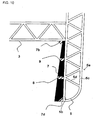
FIG. 1 is a perspective view of a railway car body structure according to a first embodiment of the present invention; -
FIG. 2 is a cross-sectional view taken at II-II ofFIG. 1 ; -
FIG. 3 is a view of a second embodiment of the present invention corresponding toFIG. 2 ; -
FIG. 4 is a perspective view of a railway car body structure according to a third embodiment of the present invention; -
FIG. 5 is a vertical cross-sectional view of a roof construction at portion V ofFIG. 4 ; -
FIG. 6 is a vertical cross-sectional view of a roof construction at portion VI ofFIG. 4 ; -
FIG. 7 is a view of a fourth embodiment of the present invention corresponding toFIG. 5 ; -
FIG. 8 is a view of the fourth embodiment of the present invention corresponding toFIG. 6 ; -
FIG. 9 is a perspective view of the railway car body structure according to a fifth embodiment of the present invention; -
FIG. 10 is a cross-sectional view taken at X-X ofFIG. 9 ; -
FIG. 11 is a view of a sixth embodiment of the present invention corresponding toFIG. 10 ; -
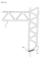
FIG. 12 is a perspective view of the railway car body structure according to a seventh embodiment of the present invention; -
FIG. 13 is a cross-sectional view taken at XIII-XIII ofFIG. 12 ; -
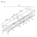
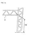
FIG. 14 is a perspective view of the railway car body structure according to an eighth embodiment of the present invention; -
FIG. 15 is a cross-sectional view taken at XV-XV ofFIG. 14 ; -
FIG. 16 is a cross-sectional view taken at XVI-XVI ofFIG. 14 ; -
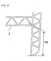
FIG. 17 is a view of a ninth embodiment of the present invention corresponding toFIG. 15 ; -
FIG. 18 is a view of a ninth embodiment of the present invention corresponding toFIG. 16 ; -
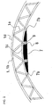
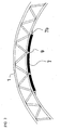
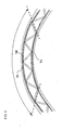
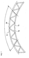
FIG. 19 is an explanatory view for describing the moment of the railway car body structure, wherein (a) is a side view of the railway car body structure, and (b) is a moment distribution diagram; and -
FIG. 20 is an explanatory view showing the distribution of strain in the perpendicular direction of the railway car body structure. - Various embodiments for carrying out the present invention are described hereafter. In the drawings, the same reference numbers as the preceding drawings used in the drawings that follow denote equivalent members, and the detailed descriptions thereof are omitted.
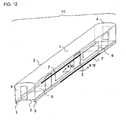
- The first embodiment of the present invention is described with reference to
FIGS. 1 and2 . A railwaycar body structure 10 is composed of aroof construction 1 constituting the upper face thereof, twoside constructions 2 constituting the side walls thereof, anunderframe 3 constituting the bottom face thereof, and twoend constructions 4 constituting the end faces thereof.Side sills 5 are disposed at the lower portion of theside constructions 2.Body bolsters 6 are disposed on theunderframe 3 for connecting theunderframe 3 and a running gear (not shown). - The
roof construction 1, theside constructions 2, theunderframe 3 and theend constructions 4 are each formed by welding plural extrusions. The extrusions used for forming theroof construction 1, theside constructions 2 and theunderframe 3 are hollow extrusions made of aluminum alloy, and their directions of extrusion correspond to the longitudinal direction of the railwaycar body structure 10. The extrusions used for forming theend construction 4 are extrusions with ribs made of aluminum alloy, and their directions of extrusion correspond to the vertical direction of the railwaycar body structure 10. - A deformed status of the railway
car body structure 10 will be described with reference toFIGS. 19 and 20. FIG. 19(a) is a side view of the railwaycar body structure 10. The railwaycar body structure 10 is supported by running gears (not shown) at the longitudinal center of thebody bolsters 6. - In addition to its own weight, the railway
car body structure 10 is loaded with aload 17 applied vertically to thecar body structure 10 by equipments such as electric appliances and passengers on board. Thevertical load 17 causes amoment distribution 18 in the railwaycar body structure 10. - In
FIG. 19(b) , the horizontal axis represents the longitudinal position in the railwaycar body structure 10, and the vertical axis represents the quantity of moment generated at the corresponding longitudinal position. In proportion to this quantity of moment, astrain distribution 19 is generated as shown inFIG. 20 . In this drawing, the vertical axis represents the position in the vertical direction of the railwaycar body structure 10, and the horizontal axis represents the quantity of strain generated at the corresponding position. - It can be seen from this drawing that the
roof construction 1 and theside sills 5 of the railwaycar body structure 10 are deformed greatly at the longitudinal center area of thestructure 10. In other words, in order to effectively improve the flexural rigidity of the railwaycar body structure 10, it is effective to suppress the deformation of theroof construction 1 and theside sills 5 at the longitudinal center portion of the railwaycar body structure 10. - Now, the structure of
FIG. 2 will be described. A reinforcingplate 7 is attached to a hollow extrusion 1b of theroof construction 1 on the inner side of the car body at the longitudinal center portion of the railwaycar body structure 10. The plate is attached by welding. The welding is performed at the outer circumference portion of the reinforcingplate 7 byfillet welding 7b, and at the inner portion of the reinforcingplate 7 by providing ahole 8 that passes through the reinforcingplate 7 and plugwelding 9 at thehole 8 to the hollow extrusion 1b. However, the inner portion subjected to plug welding does not necessarily have to have thehole 8 filled completely, as long as the plate is welded on in a strengthening manner, so the inner portion can also be attached via fillet welding. Thehole 8 is welded onto the crossing point of aface plate 1c of the hollow extrusion 1b facing the inner side of the car and a connectingplate 1e connecting theface plate 1c and theface plate 1d facing the outer side of the car of the hollow extrusion 1b The welding can be performed either continuously or intermittently at the crossing point along the longitudinal direction of the car body. - The range in which the reinforcing
plate 7 is adhered to the railwaycar body structure 10 in the longitudinal direction of the body is between the two body bolsters 6, substantially symmetric from the longitudinal center of the railwaycar body structure 10. - The range in which the reinforcing
plate 7 is adhered to the railwaycar body structure 10 in the width direction (width direction of the car body, which is equal to the orthogonal direction with respect to the longitudinal direction of the car body) is approximately half the length in the width direction of theroof construction 1, substantially symmetric from the width-direction center of theroof construction 1. - The above range and the thickness of the reinforcing
plate 7 can vary depending on the flexural rigidity required for the railwaycar body structure 10, the mass restriction for the railwaycar body structure 10, the allowable space, the work restriction and so on. The reinforcingplate 7 can be formed of plural plates. The change in thickness of the reinforcingplate 7 can be corresponded with by changing the plate thickness of theface plates - The thickness of the reinforcing
plate 7 is increased gradually toward the center of the car body in the width direction. In other words, the thickness of the reinforcingplate 7 is increased gradually corresponding to the increase in vertical height of theroof construction 1. - This is because the vertical height of the
roof construction 1 generally increases toward the center of width of the car body. The surface of the reinforcingplate 7 facing the outer side of the car (the surface arranged along theface plate 1c of the hollow extrusion constituting theroof construction 1 positioned facing the inner side of the car) is machined to correspond to the inner side of theroof construction 1 facing the inner side of the car, so that the surface can be in contact with theface plate 1c. The side of the reinforcingplate 7 on the inner side of the car is not machined from the view point of reducing processing costs. - The material of the reinforcing
plate 7 is aluminum alloy. Other materials such as steel can be used to form the reinforcingplate 7. If the reinforcingplate 7 is formed of material such as steel having a high modulus of longitudinal elasticity, the rigidity and space thereof are improved, but the recycle ability and the welding ability are deteriorated. If various materials are welded to form the car structure, the different materials must be separated before recycling. Further, it is difficult to mainly use welding as a means for bonding together various materials. - According to this arrangement, the deformation of the
roof construction 1 at the longitudinal center of the railwaycar body structure 10 is suppressed, and the flexural rigidity of the railwaycar body structure 10 can be improved effectively. Since the arrangement suppresses the bending vibration of the railway car body in the vertical direction, it enables to provide a railway car having a superior riding quality. - According to the present embodiment, the reinforcing
plate 7 is attached to the side of the roof construction facing the inner side of the car body, so it does not deteriorate the appearance of the car body compared to when the reinforcing plate is attached to the outer side of the car. - The second embodiment of the present invention will be described with reference to
FIG. 3. FIG. 3 illustrates an example in which a reinforcingplate 7 having a uniform thickness is provided. The reinforcingplate 7 is bent via machining. The fixing structure of the reinforcingplate 7 is the same as that ofFIG. 2 . - According to this embodiment, the machining of the side of the reinforcing
plate 7 facing the outer side of the car becomes unnecessary, by which the costs can be cut down. - The third embodiment of the present invention will be described with reference to
FIGS. 4 ,5 and6 . This embodiment does not utilize the reinforcingplate 7. - The thickness of the
face plate 1c of the hollow extrusion constituting theroof construction 1 facing the inner side of the car body and theface plate 1d facing the outer side thereof at the longitudinal center portion of the roof construction 1 (portion V of the drawing) is greater than the thickness of theface plates - According to this embodiment, the reinforcing
plate 7 becomes unnecessary, which is advantageous from the viewpoint of space, number of components, welding costs and so on. Further, it should be noted that the frames illustrated by the dashed lines between portions IV and portion V are for indicating sections, and no such frame is actually formed. - The fourth embodiment of the present invention will be described with reference to
FIGS. 7 and8 . InFIG. 4 , the material of thehollow extrusion 11 at the longitudinal center portion V of theroof construction 1 has a high modulus of longitudinal elasticity. Thehollow extrusions 12 constituting the longitudinal ends VI of theroof construction 1 are formed of normal hollow extrusion material. If the hollow extrusion at the longitudinal center portion V cannot be formed of hollow extrusions, it can be formed by welding or mechanically connecting a connecting plate (steel-based material) 1e to normal panels (steel-based material) 1c and 1d. - The fifth embodiment of the present invention will be described with reference to
FIGS. 9 and10 . Reinforcingplates 7 are adhered to faceplates 5b on perpendicular sides of the side sills lower than the horizontal plane of the underframe at the inner side of the car body (inner side does not mean that the side faces the interior of the car, but means that it does not face the outer side of the car) at the longitudinal center portion of the railwaycar body structure 10. The longitudinal range in which the reinforcingplate 7 is attached to the railwaycar body structure 10 is between the two body bolsters 6, substantially symmetric from the longitudinal center of the railwaycar body structure 10. The range in the vertical direction in which the reinforcingplate 7 is attached is theface plates 5b on the perpendicular plane of theside sills 5, and theplate 7 is attached by fillet welding 7c to the lower surface of theunderframe 3. It can be welded to theface plate 5b instead of welding to the lower surface of theunderframe 3. Furthermore, the lower end of the reinforcingplate 7 can reach and be welded to the lower end of the side sill, but it can also end at the middle of the perpendicular plane. A groove is formed to the lower end of the reinforcingplate 7, using which the plate can be welded viagroove welding 7d. - The middle area between the upper and lower portions of the reinforcing
plate 7 are attached by plug welding 9 to the crossing points between theface plate 5b of thehollow extrusion 5a on the inner side of the car body and the connectingplates 5d connecting theface plate 5b with theface plate 5c on the outer side of the car body.Holes 8 are formed to the reinforcingplate 7 corresponding to the areas to be subjected to plugwelding 9. Fillet welding can be performed instead ofplug welding 9. - The thickness of the reinforcing
plate 7 is thinner near the underframe than the lower end thereof. This varied thickness is formed via machining. The surface of the reinforcingplate 7 facing the outer side of the car body is machined to fit to the surface of the side sill facing the inner side of the car body. If the perpendicular surface of theside sill 5 facing the inner side of the car body is straight, the surface of the reinforcingplate 7 facing the outer side of the car body is not machined so as to reduce machining costs. The surface of the reinforcingplate 7 facing the inner side of the car body is machined to correspond to the necessary thickness. - The material of the reinforcing
plate 7 is aluminum alloy. Other materials such as steel can be used to form the reinforcingplate 7. If the reinforcingplate 7 is formed of material such as steel having a high modulus of longitudinal elasticity, the rigidity and space thereof are improved, but the recycle ability and the welding ability are deteriorated. If various materials are welded to form the car structure, the different materials must be separated before recycling. Further, it is difficult to mainly use welding as a means for bonding various materials. - The above range and the thickness of the reinforcing
plate 7 can vary depending on the flexural rigidity required for the railwaycar body structure 10, the mass restriction for the railwaycar body structure 10, the allowable space, the work restriction and so on. The reinforcingplate 7 can be formed of plural plates. - If the reinforcing
plate 7 is formed of plural panels, the plural panels are welded together via butt welding. If the reinforcingplate 7 is formed of plural panels, the shipping and handling properties thereof are improved but the required number of components and welding costs are disadvantageously increased. - The reinforcing
plate 7 can be attached to theroof construction 1 via other methods, such as riveting or bolt engagement. Such methods are mainly used when bonding different metals together. - According to this arrangement, the deformation of the
side sills 5 at the longitudinal center portion of the railwaycar body structure 10 is suppressed, by which the flexural rigidity of the railwaycar body structure 10 is improved effectively. Since the arrangement suppresses the bending vibration of the railway car body in the vertical direction, it provides a railway car having a superior riding quality. Since the reinforcingplate 7 is increased in thickness toward the lower end, it can correspond to the strain increasing away from the vertical center of the car body, as shown inFIG. 20 . - The sixth embodiment of the present invention will be described with reference to
FIG. 11. FIG. 11 illustrates an example in which the thickness of the reinforcingplate 7 is uniform. If theperpendicular surface 5b of theside sill 5 facing the inner side of the car body is curved, the reinforcingplate 7 is also curved to correspond to the curved inner surface. If the perpendicular surface of theside sill 5 facing the inner side of the car body is straight, the surface of the reinforcingplate 7 facing the outer side of the car body is not machined so as to reduce machining costs. - The seventh embodiment of the present invention will be described with reference to
FIGS. 12 and13 . According to this embodiment, the reinforcingplate 7 is curved in an arc to correspond to a curved surface at the lowermost surface of theside sill 5. The side of the reinforcingplate 7 facing the outer side of the car body is attached to the hollow extrusion viafillet welding 7e. A groove is provided to the reinforcing plate at a portion near the inner side of the car body between the hollow extrusion, which is used to performgroove welding 7g. - As shown in
FIG. 20 , since the strain increases away from the vertical center of the car body, the reinforcingplate 7 can be conveniently attached to areas where there is large strain. - According to this arrangement, the reinforcing plate can be downsized.
- The eighth embodiment of the present invention will be described with reference to
FIGS. 14 ,15 and16 . The present embodiment suppresses the deformation of theside sill 5 not by attaching a reinforcingplate 7 but by increasing the thickness of theside sill 5. The thickness of alower portion 16 of theside sill 5 at the longitudinal center portion (referred to as portion XV) of the railwaycar body structure 10 is thicker than alower portion 15 of theside sill 5 at the longitudinal ends (referred to as portion XVI) of the railwaycar body structure 10. - According to this arrangement, the attachment of a reinforcing
plate 7 is not necessary, which is advantageous from the viewpoint of effective space, number of components and welding costs. - The ninth embodiment of the present invention will be described with reference to
FIGS. 17 and18 . According to this embodiment, the modulus of longitudinal elasticity of the material forming thelower portion 16 of theside sill 5 at the longitudinal center portion (referred to as portion XV) of theside sill 5 is greater than the modulus of longitudinal elasticity of the material forming thelower portion 15 of theside sill 5 at the longitudinal ends (referred to as portion XVI) thereof. - According to this arrangement, there is no need to increase the thickness of the
lower portion 16 of theside sill 5 at the longitudinal center portion (portion XV) of theside sill 5, so the shape of theside sills 5, in other words, the shape of the railwaycar body structure 10, can be made uniform.
Claims (12)
- A railway or monorail car body structure having a roof construction (1) comprising a hollow extrusion (1b) whose extrusion direction corresponds to the longitudinal direction of the car body structure, characterised in that said roof construction (1) has a higher rigidity at a first portion of the car body structure, which first portion is at the centre of the car body structure with respect to the longitudinal direction thereof, than at the other portions of the roof construction (1), said other portions including end portions of the car body structure which are located in the longitudinal direction between said first portion and the respective longitudinal ends and extend from said first portion to the respective longitudinal ends.
- The car body structure according to claim 1, wherein to provide said higher rigidity at said first portion, a reinforcing plate (7) is adhered to a face plate (1c) of said hollow extrusion (1b) facing the inside of the car body structure.
- The car body structure according to claim 2, wherein said reinforcing plate (7) has a thickness which increases gradually towards the centre of the roof construction in the width direction thereof.
- The car body structure according to claim 2 or 3, wherein said hollow extrusion (1b) to which said reinforcing plate is adhered has an inner face plate (1c) facing the inside of the car body structure, an outer face plate (1d) and a connecting plate (1e) connecting said inner and outer face plates, and said reinforcing plate is welded to said inner face plate (1c) by fillet welding of the whole circumference of the reinforcing plate and by plug welding to a junction point of said inner face plate (1c) and said connecting plate (1e).
- The car body structure according to claim 1, wherein said hollow extrusion (1b) comprises an outer face plate (1d) and an inner face plate (1c); and
said face plates (1c, 1d) have a greater thickness at said centre portion of the car body structure than the thickness of said face plates of the longitudinal ends thereof. - The car body structure according to claim 1, wherein the material constituting said roof construction (1) at said first portion of the car body structure has a higher modulus of longitudinal elasticity than the material constituting the other portions of the roof construction.
- The car body structure according to claim 1, wherein the modulus of longitudinal elasticity of the material constituting the roof construction at said first portion increases toward the centre in a width direction of the roof construction.
- A railway or monorail car body structure having an underframe construction comprising a horizontal underframe body (3) and two side constructions (2) each including a side sill (5) extending downwardly from below a side edge of said horizontal underframe body (3), wherein said underframe body and said side constructions including said side sills are each formed of hollow extrusions which are welded together and have their extrusion directions corresponding to the longitudinal direction of the car body structure,
characterised in that
each said side sill has a higher rigidity at a first centre portion of the car body structure, which first portion is at the centre of the car body structure with respect to the longitudinal direction thereof, than at the other portions of the side sill, said other portions including end portions of the car body structure which are located in the longitudinal direction between said first portion and the respective longitudinal ends of the car body structure and extend from said first portion to the respective longitudinal ends. - The car body structure according to claim 8, wherein said higher rigidity is provided by adhering a reinforcing plate (7) to the side of each said side sill facing inwardly of the car body structure.
- The car body structure according to claim 9, wherein the thickness of said reinforcing plate (7) increases gradually towards the lower end of the side sill.
- The car body structure according to claim 9, wherein each said side sill is formed of one said hollow extrusion which has an inner face plate facing inwardly of said car body structure, an outer face plate and a connecting member connecting said inner and outer face plates, and said reinforcing plate is welded to said inner face plate by fillet welding of the whole circumference of the reinforcing plate and by plug welding to a junction point of said inner face plate and said connecting plate.
- The car body structure according to claim 8, wherein a modulus of longitudinal elasticity of a material forming a lower portion of each side sill at said longitudinal centre portion of the car body structure is increased gradually toward the lower end portion of the side sill.
Applications Claiming Priority (1)
| Application Number | Priority Date | Filing Date | Title |
|---|---|---|---|
| JP2005109591A JP2006290027A (en) | 2005-04-06 | 2005-04-06 | Vehicle body structure |
Publications (2)
| Publication Number | Publication Date |
|---|---|
| EP1710144A1 EP1710144A1 (en) | 2006-10-11 |
| EP1710144B1 true EP1710144B1 (en) | 2010-11-03 |
Family
ID=36643412
Family Applications (1)
| Application Number | Title | Priority Date | Filing Date |
|---|---|---|---|
| EP05255426A Active EP1710144B1 (en) | 2005-04-06 | 2005-09-05 | Car body structure |
Country Status (7)
| Country | Link |
|---|---|
| US (2) | US7438001B2 (en) |
| EP (1) | EP1710144B1 (en) |
| JP (1) | JP2006290027A (en) |
| KR (1) | KR100747139B1 (en) |
| CN (1) | CN100443340C (en) |
| AT (1) | ATE486756T1 (en) |
| DE (1) | DE602005024515D1 (en) |
Cited By (1)
| Publication number | Priority date | Publication date | Assignee | Title |
|---|---|---|---|---|
| DE102012209049A1 (en) * | 2012-05-30 | 2013-12-05 | Siemens Aktiengesellschaft | Car body construction for vehicles |
Families Citing this family (16)
| Publication number | Priority date | Publication date | Assignee | Title |
|---|---|---|---|---|
| JP4266024B2 (en) * | 2006-03-28 | 2009-05-20 | 株式会社日立製作所 | Rail vehicle, manufacturing method thereof, and hollow shape material used therefor |
| US8240255B2 (en) * | 2006-11-30 | 2012-08-14 | The Kinki Sharyo Co., Ltd. | Body frame structure of railway vehicle |
| US8297202B2 (en) * | 2006-12-06 | 2012-10-30 | The Kinki Sharyo Co., Ltd. | Body frame structure of railway vehicle |
| TWI395683B (en) * | 2009-03-30 | 2013-05-11 | Kawasaki Heavy Ind Ltd | Railway vehicle structure and manufacturing method thereof |
| JP5427092B2 (en) * | 2010-04-02 | 2014-02-26 | 日本車輌製造株式会社 | Railway vehicle |
| JP5466114B2 (en) * | 2010-09-02 | 2014-04-09 | 株式会社日立製作所 | Railway vehicle structure |
| WO2012111345A1 (en) * | 2011-02-17 | 2012-08-23 | 東日本旅客鉄道株式会社 | Railroad vehicle |
| JP5685494B2 (en) * | 2011-06-14 | 2015-03-18 | 株式会社日立製作所 | Railway vehicle body structure with wiring and piping modules |
| WO2013107023A1 (en) * | 2012-01-19 | 2013-07-25 | General Electric Company | Vehicle body and manufacturing method |
| US9499179B2 (en) * | 2012-02-23 | 2016-11-22 | Kawasaki Jukogyo Kabushiki Kaisha | Railroad vehicle provided with low roof structure |
| US9260117B2 (en) * | 2012-04-12 | 2016-02-16 | Trinity Industries, Inc. | Composite roof conversion |
| USD756843S1 (en) * | 2012-11-21 | 2016-05-24 | Central Japan Railway Company | Passenger carrying car |
| CN103386573B (en) * | 2013-07-26 | 2016-01-27 | 南车戚墅堰机车有限公司 | PN locomotive cooling chamber cooling fan installing plate assembly tool |
| US9440661B2 (en) * | 2014-03-06 | 2016-09-13 | Siemens Industry, Inc. | Integrated ceiling assembly for railcars |
| CN104015740A (en) * | 2014-06-23 | 2014-09-03 | 南车戚墅堰机车有限公司 | Car body structure of internal combustion locomotive with light weight and high carrying capacity |
| CN105035103B (en) * | 2015-09-08 | 2018-06-15 | 安徽安凯汽车股份有限公司 | Top plate press strip in car |
Family Cites Families (16)
| Publication number | Priority date | Publication date | Assignee | Title |
|---|---|---|---|---|
| US1679460A (en) | 1923-10-11 | 1928-08-07 | Chicago Cleveland Car Roofing | Car roof |
| US2083553A (en) * | 1934-07-16 | 1937-06-15 | Pullman Standard Car Mfg Co | Top sill |
| US2155677A (en) | 1937-03-10 | 1939-04-25 | P H Murphy Co | Car roof |
| US3102498A (en) | 1960-04-26 | 1963-09-03 | Budd Co | Sidewall-to-floor connection for vehicles |
| DE2452565A1 (en) * | 1974-11-06 | 1976-05-13 | Waggon Union Gmbh | Closed bogie mounted railway goods wagon body - with constant section continuous outside long bearers and centre lattice bearers (BR090376) |
| SE444921B (en) * | 1982-06-01 | 1986-05-20 | Asea Ab | CARBON BASKET FOR RAILWAY VEHICLES IN LIGHT METAL WITH FIBER COMPOSITION BAND UNITED WITH LIGHT METAL PROFILES |
| CN85101670B (en) * | 1985-04-02 | 1987-03-11 | 川崎重工业株式会社 | Vehicle body frame construction, more particularly for railsoad rolling stock |
| JPH0676060B2 (en) * | 1988-07-15 | 1994-09-28 | 日本車輌製造株式会社 | Railway vehicle structure |
| JP2604226B2 (en) | 1989-03-20 | 1997-04-30 | 財団法人 鉄道総合技術研究所 | Railcar structure |
| JP2821163B2 (en) * | 1989-03-22 | 1998-11-05 | 株式会社日立製作所 | Railcar roof structure |
| US5433151A (en) * | 1990-09-07 | 1995-07-18 | Hitachi, Ltd. | Railway car body structures and methods of making them using welded honeycomb panels connected in an edge to edge relation |
| JPH04368276A (en) * | 1991-06-14 | 1992-12-21 | Railway Technical Res Inst | Body damping mechanism in rolling stock |
| KR950008262A (en) * | 1993-09-20 | 1995-04-17 | 가나이 쯔도무 | Railway vehicle and its interior decoration method |
| NL1006199C1 (en) * | 1997-03-14 | 1998-09-15 | Fokker Special Products | Vehicle construction. |
| ES2281134T3 (en) * | 1998-09-28 | 2007-09-16 | Hitachi, Ltd. | BODYWORK. |
| US6550397B2 (en) * | 2001-03-27 | 2003-04-22 | Hitachi, Ltd. | Car body |
-
2005
- 2005-04-06 JP JP2005109591A patent/JP2006290027A/en active Pending
- 2005-08-31 KR KR1020050080496A patent/KR100747139B1/en not_active IP Right Cessation
- 2005-09-01 CN CNB2005100996691A patent/CN100443340C/en active Active
- 2005-09-02 US US11/217,288 patent/US7438001B2/en not_active Expired - Fee Related
- 2005-09-05 EP EP05255426A patent/EP1710144B1/en active Active
- 2005-09-05 DE DE602005024515T patent/DE602005024515D1/en active Active
- 2005-09-05 AT AT05255426T patent/ATE486756T1/en not_active IP Right Cessation
-
2008
- 2008-05-06 US US12/115,614 patent/US20080276831A1/en not_active Abandoned
Cited By (1)
| Publication number | Priority date | Publication date | Assignee | Title |
|---|---|---|---|---|
| DE102012209049A1 (en) * | 2012-05-30 | 2013-12-05 | Siemens Aktiengesellschaft | Car body construction for vehicles |
Also Published As
| Publication number | Publication date |
|---|---|
| KR100747139B1 (en) | 2007-08-07 |
| JP2006290027A (en) | 2006-10-26 |
| EP1710144A1 (en) | 2006-10-11 |
| US20060225604A1 (en) | 2006-10-12 |
| US20080276831A1 (en) | 2008-11-13 |
| KR20060106584A (en) | 2006-10-12 |
| CN100443340C (en) | 2008-12-17 |
| US7438001B2 (en) | 2008-10-21 |
| DE602005024515D1 (en) | 2010-12-16 |
| CN1843819A (en) | 2006-10-11 |
| ATE486756T1 (en) | 2010-11-15 |
Similar Documents
| Publication | Publication Date | Title |
|---|---|---|
| EP1710144B1 (en) | Car body structure | |
| US8297202B2 (en) | Body frame structure of railway vehicle | |
| US11021193B2 (en) | Side rail and manufacturing method for side rail | |
| JP4440832B2 (en) | Railway frame structure | |
| CN1101777C (en) | High-hardness floor for lift cage | |
| JP4979390B2 (en) | Vehicle structure | |
| JP4394921B2 (en) | Hollow member reinforcement structure | |
| JPH09254786A (en) | Vehicle body for railway rolling stock | |
| JP6706640B2 (en) | Vehicle rear opening structure | |
| CN209395881U (en) | Beam and automobile with the beam | |
| JP2008001363A (en) | Vehicle body structure | |
| JPH11139348A (en) | Structure for reinforcing partition panel of automobile | |
| JP2011143808A (en) | Railroad vehicle body structure | |
| CN219635337U (en) | Rear floor structure and vehicle | |
| JP2934582B2 (en) | Railcar structure | |
| CN217515240U (en) | Electric automobile front wall beam | |
| JP2010064505A (en) | Reinforcing structure of car body longitudinal member | |
| CN211893407U (en) | Automobile body structure on automobile | |
| JP2018052280A (en) | Vehicle structure | |
| EP4177129A1 (en) | Body bolster structure for railway vehicle, and railway vehicle | |
| JP2008024304A (en) | Vehicle structural body | |
| JPH09142299A (en) | Car body of rolling stock | |
| JP2007090960A (en) | Car body structure of railway vehicle | |
| JPH061235A (en) | Rolling stock body | |
| JP6332390B2 (en) | Lower body structure of the vehicle |
Legal Events
| Date | Code | Title | Description |
|---|---|---|---|
| PUAI | Public reference made under article 153(3) epc to a published international application that has entered the european phase |
Free format text: ORIGINAL CODE: 0009012 |
|
| 17P | Request for examination filed |
Effective date: 20050926 |
|
| AK | Designated contracting states |
Kind code of ref document: A1 Designated state(s): AT BE BG CH CY CZ DE DK EE ES FI FR GB GR HU IE IS IT LI LT LU LV MC NL PL PT RO SE SI SK TR |
|
| AX | Request for extension of the european patent |
Extension state: AL BA HR MK YU |
|
| AKX | Designation fees paid |
Designated state(s): AT BE BG CH CY CZ DE DK EE ES FI FR GB GR HU IE IS IT LI LT LU LV MC NL PL PT RO SE SI SK TR |
|
| 17Q | First examination report despatched |
Effective date: 20080723 |
|
| GRAP | Despatch of communication of intention to grant a patent |
Free format text: ORIGINAL CODE: EPIDOSNIGR1 |
|
| GRAS | Grant fee paid |
Free format text: ORIGINAL CODE: EPIDOSNIGR3 |
|
| GRAA | (expected) grant |
Free format text: ORIGINAL CODE: 0009210 |
|
| AK | Designated contracting states |
Kind code of ref document: B1 Designated state(s): AT BE BG CH CY CZ DE DK EE ES FI FR GB GR HU IE IS IT LI LT LU LV MC NL PL PT RO SE SI SK TR |
|
| REG | Reference to a national code |
Ref country code: GB Ref legal event code: FG4D |
|
| REG | Reference to a national code |
Ref country code: CH Ref legal event code: EP |
|
| REG | Reference to a national code |
Ref country code: IE Ref legal event code: FG4D |
|
| REF | Corresponds to: |
Ref document number: 602005024515 Country of ref document: DE Date of ref document: 20101216 Kind code of ref document: P |
|
| REG | Reference to a national code |
Ref country code: NL Ref legal event code: VDEP Effective date: 20101103 |
|
| LTIE | Lt: invalidation of european patent or patent extension |
Effective date: 20101103 |
|
| PG25 | Lapsed in a contracting state [announced via postgrant information from national office to epo] |
Ref country code: LT Free format text: LAPSE BECAUSE OF FAILURE TO SUBMIT A TRANSLATION OF THE DESCRIPTION OR TO PAY THE FEE WITHIN THE PRESCRIBED TIME-LIMIT Effective date: 20101103 |
|
| PG25 | Lapsed in a contracting state [announced via postgrant information from national office to epo] |
Ref country code: SI Free format text: LAPSE BECAUSE OF FAILURE TO SUBMIT A TRANSLATION OF THE DESCRIPTION OR TO PAY THE FEE WITHIN THE PRESCRIBED TIME-LIMIT Effective date: 20101103 Ref country code: SE Free format text: LAPSE BECAUSE OF FAILURE TO SUBMIT A TRANSLATION OF THE DESCRIPTION OR TO PAY THE FEE WITHIN THE PRESCRIBED TIME-LIMIT Effective date: 20101103 Ref country code: PT Free format text: LAPSE BECAUSE OF FAILURE TO SUBMIT A TRANSLATION OF THE DESCRIPTION OR TO PAY THE FEE WITHIN THE PRESCRIBED TIME-LIMIT Effective date: 20110303 Ref country code: IS Free format text: LAPSE BECAUSE OF FAILURE TO SUBMIT A TRANSLATION OF THE DESCRIPTION OR TO PAY THE FEE WITHIN THE PRESCRIBED TIME-LIMIT Effective date: 20110303 Ref country code: NL Free format text: LAPSE BECAUSE OF FAILURE TO SUBMIT A TRANSLATION OF THE DESCRIPTION OR TO PAY THE FEE WITHIN THE PRESCRIBED TIME-LIMIT Effective date: 20101103 Ref country code: FI Free format text: LAPSE BECAUSE OF FAILURE TO SUBMIT A TRANSLATION OF THE DESCRIPTION OR TO PAY THE FEE WITHIN THE PRESCRIBED TIME-LIMIT Effective date: 20101103 Ref country code: BG Free format text: LAPSE BECAUSE OF FAILURE TO SUBMIT A TRANSLATION OF THE DESCRIPTION OR TO PAY THE FEE WITHIN THE PRESCRIBED TIME-LIMIT Effective date: 20110203 Ref country code: LV Free format text: LAPSE BECAUSE OF FAILURE TO SUBMIT A TRANSLATION OF THE DESCRIPTION OR TO PAY THE FEE WITHIN THE PRESCRIBED TIME-LIMIT Effective date: 20101103 Ref country code: AT Free format text: LAPSE BECAUSE OF FAILURE TO SUBMIT A TRANSLATION OF THE DESCRIPTION OR TO PAY THE FEE WITHIN THE PRESCRIBED TIME-LIMIT Effective date: 20101103 |
|
| PG25 | Lapsed in a contracting state [announced via postgrant information from national office to epo] |
Ref country code: GR Free format text: LAPSE BECAUSE OF FAILURE TO SUBMIT A TRANSLATION OF THE DESCRIPTION OR TO PAY THE FEE WITHIN THE PRESCRIBED TIME-LIMIT Effective date: 20110204 |
|
| PG25 | Lapsed in a contracting state [announced via postgrant information from national office to epo] |
Ref country code: EE Free format text: LAPSE BECAUSE OF FAILURE TO SUBMIT A TRANSLATION OF THE DESCRIPTION OR TO PAY THE FEE WITHIN THE PRESCRIBED TIME-LIMIT Effective date: 20101103 Ref country code: CZ Free format text: LAPSE BECAUSE OF FAILURE TO SUBMIT A TRANSLATION OF THE DESCRIPTION OR TO PAY THE FEE WITHIN THE PRESCRIBED TIME-LIMIT Effective date: 20101103 Ref country code: BE Free format text: LAPSE BECAUSE OF FAILURE TO SUBMIT A TRANSLATION OF THE DESCRIPTION OR TO PAY THE FEE WITHIN THE PRESCRIBED TIME-LIMIT Effective date: 20101103 Ref country code: ES Free format text: LAPSE BECAUSE OF FAILURE TO SUBMIT A TRANSLATION OF THE DESCRIPTION OR TO PAY THE FEE WITHIN THE PRESCRIBED TIME-LIMIT Effective date: 20110214 |
|
| PG25 | Lapsed in a contracting state [announced via postgrant information from national office to epo] |
Ref country code: SK Free format text: LAPSE BECAUSE OF FAILURE TO SUBMIT A TRANSLATION OF THE DESCRIPTION OR TO PAY THE FEE WITHIN THE PRESCRIBED TIME-LIMIT Effective date: 20101103 Ref country code: DK Free format text: LAPSE BECAUSE OF FAILURE TO SUBMIT A TRANSLATION OF THE DESCRIPTION OR TO PAY THE FEE WITHIN THE PRESCRIBED TIME-LIMIT Effective date: 20101103 Ref country code: PL Free format text: LAPSE BECAUSE OF FAILURE TO SUBMIT A TRANSLATION OF THE DESCRIPTION OR TO PAY THE FEE WITHIN THE PRESCRIBED TIME-LIMIT Effective date: 20101103 Ref country code: RO Free format text: LAPSE BECAUSE OF FAILURE TO SUBMIT A TRANSLATION OF THE DESCRIPTION OR TO PAY THE FEE WITHIN THE PRESCRIBED TIME-LIMIT Effective date: 20101103 |
|
| PLBE | No opposition filed within time limit |
Free format text: ORIGINAL CODE: 0009261 |
|
| STAA | Information on the status of an ep patent application or granted ep patent |
Free format text: STATUS: NO OPPOSITION FILED WITHIN TIME LIMIT |
|
| 26N | No opposition filed |
Effective date: 20110804 |
|
| REG | Reference to a national code |
Ref country code: DE Ref legal event code: R097 Ref document number: 602005024515 Country of ref document: DE Effective date: 20110804 |
|
| PG25 | Lapsed in a contracting state [announced via postgrant information from national office to epo] |
Ref country code: IT Free format text: LAPSE BECAUSE OF FAILURE TO SUBMIT A TRANSLATION OF THE DESCRIPTION OR TO PAY THE FEE WITHIN THE PRESCRIBED TIME-LIMIT Effective date: 20101103 |
|
| PG25 | Lapsed in a contracting state [announced via postgrant information from national office to epo] |
Ref country code: MC Free format text: LAPSE BECAUSE OF NON-PAYMENT OF DUE FEES Effective date: 20110930 |
|
| REG | Reference to a national code |
Ref country code: CH Ref legal event code: PL |
|
| REG | Reference to a national code |
Ref country code: IE Ref legal event code: MM4A |
|
| PG25 | Lapsed in a contracting state [announced via postgrant information from national office to epo] |
Ref country code: IE Free format text: LAPSE BECAUSE OF NON-PAYMENT OF DUE FEES Effective date: 20110905 Ref country code: LI Free format text: LAPSE BECAUSE OF NON-PAYMENT OF DUE FEES Effective date: 20110930 Ref country code: CH Free format text: LAPSE BECAUSE OF NON-PAYMENT OF DUE FEES Effective date: 20110930 |
|
| PG25 | Lapsed in a contracting state [announced via postgrant information from national office to epo] |
Ref country code: CY Free format text: LAPSE BECAUSE OF EXPIRATION OF PROTECTION Effective date: 20101103 Ref country code: LU Free format text: LAPSE BECAUSE OF NON-PAYMENT OF DUE FEES Effective date: 20110905 |
|
| PG25 | Lapsed in a contracting state [announced via postgrant information from national office to epo] |
Ref country code: TR Free format text: LAPSE BECAUSE OF FAILURE TO SUBMIT A TRANSLATION OF THE DESCRIPTION OR TO PAY THE FEE WITHIN THE PRESCRIBED TIME-LIMIT Effective date: 20101103 |
|
| PG25 | Lapsed in a contracting state [announced via postgrant information from national office to epo] |
Ref country code: HU Free format text: LAPSE BECAUSE OF FAILURE TO SUBMIT A TRANSLATION OF THE DESCRIPTION OR TO PAY THE FEE WITHIN THE PRESCRIBED TIME-LIMIT Effective date: 20101103 |
|
| REG | Reference to a national code |
Ref country code: FR Ref legal event code: PLFP Year of fee payment: 12 |
|
| REG | Reference to a national code |
Ref country code: FR Ref legal event code: PLFP Year of fee payment: 13 |
|
| REG | Reference to a national code |
Ref country code: FR Ref legal event code: PLFP Year of fee payment: 14 |
|
| PGFP | Annual fee paid to national office [announced via postgrant information from national office to epo] |
Ref country code: GB Payment date: 20220728 Year of fee payment: 18 Ref country code: DE Payment date: 20220803 Year of fee payment: 18 |
|
| PGFP | Annual fee paid to national office [announced via postgrant information from national office to epo] |
Ref country code: FR Payment date: 20220808 Year of fee payment: 18 |