EP1705149A2 - Device for automatic opening and closing of reaction vessels - Google Patents
Device for automatic opening and closing of reaction vessels Download PDFInfo
- Publication number
- EP1705149A2 EP1705149A2 EP06014143A EP06014143A EP1705149A2 EP 1705149 A2 EP1705149 A2 EP 1705149A2 EP 06014143 A EP06014143 A EP 06014143A EP 06014143 A EP06014143 A EP 06014143A EP 1705149 A2 EP1705149 A2 EP 1705149A2
- Authority
- EP
- European Patent Office
- Prior art keywords
- openings
- gripper
- perforated plate
- reaction vessels
- gripping
- Prior art date
- Legal status (The legal status is an assumption and is not a legal conclusion. Google has not performed a legal analysis and makes no representation as to the accuracy of the status listed.)
- Granted
Links
- 238000006243 chemical reaction Methods 0.000 title claims abstract description 75
- 230000007246 mechanism Effects 0.000 claims abstract description 15
- 238000005520 cutting process Methods 0.000 claims description 17
- 238000006073 displacement reaction Methods 0.000 claims description 10
- 238000003780 insertion Methods 0.000 description 3
- 230000037431 insertion Effects 0.000 description 3
- 230000009471 action Effects 0.000 description 2
- 230000008901 benefit Effects 0.000 description 2
- 230000002093 peripheral effect Effects 0.000 description 2
- 238000011002 quantification Methods 0.000 description 2
- 238000005070 sampling Methods 0.000 description 2
- 125000006850 spacer group Chemical group 0.000 description 2
- 239000000126 substance Substances 0.000 description 2
- 241000711549 Hepacivirus C Species 0.000 description 1
- 241000713772 Human immunodeficiency virus 1 Species 0.000 description 1
- 238000010521 absorption reaction Methods 0.000 description 1
- 230000001154 acute effect Effects 0.000 description 1
- 230000032683 aging Effects 0.000 description 1
- 230000005540 biological transmission Effects 0.000 description 1
- 239000003153 chemical reaction reagent Substances 0.000 description 1
- 239000004020 conductor Substances 0.000 description 1
- 238000013461 design Methods 0.000 description 1
- 230000010354 integration Effects 0.000 description 1
- 239000007788 liquid Substances 0.000 description 1
- 230000014759 maintenance of location Effects 0.000 description 1
- 238000004519 manufacturing process Methods 0.000 description 1
- 239000000463 material Substances 0.000 description 1
- 238000000034 method Methods 0.000 description 1
- 230000004048 modification Effects 0.000 description 1
- 238000012986 modification Methods 0.000 description 1
- 238000002360 preparation method Methods 0.000 description 1
- 210000002966 serum Anatomy 0.000 description 1
- 229920002545 silicone oil Polymers 0.000 description 1
- 238000005476 soldering Methods 0.000 description 1
- 210000002023 somite Anatomy 0.000 description 1
- 238000012546 transfer Methods 0.000 description 1
Images


Classifications
-
- B—PERFORMING OPERATIONS; TRANSPORTING
- B01—PHYSICAL OR CHEMICAL PROCESSES OR APPARATUS IN GENERAL
- B01L—CHEMICAL OR PHYSICAL LABORATORY APPARATUS FOR GENERAL USE
- B01L9/00—Supporting devices; Holding devices
- B01L9/06—Test-tube stands; Test-tube holders
-
- B—PERFORMING OPERATIONS; TRANSPORTING
- B67—OPENING, CLOSING OR CLEANING BOTTLES, JARS OR SIMILAR CONTAINERS; LIQUID HANDLING
- B67B—APPLYING CLOSURE MEMBERS TO BOTTLES JARS, OR SIMILAR CONTAINERS; OPENING CLOSED CONTAINERS
- B67B7/00—Hand- or power-operated devices for opening closed containers
- B67B7/18—Hand- or power-operated devices for opening closed containers for removing threaded caps
- B67B7/182—Hand- or power-operated devices for opening closed containers for removing threaded caps power-operated
-
- B—PERFORMING OPERATIONS; TRANSPORTING
- B01—PHYSICAL OR CHEMICAL PROCESSES OR APPARATUS IN GENERAL
- B01L—CHEMICAL OR PHYSICAL LABORATORY APPARATUS FOR GENERAL USE
- B01L2200/00—Solutions for specific problems relating to chemical or physical laboratory apparatus
- B01L2200/02—Adapting objects or devices to another
- B01L2200/025—Align devices or objects to ensure defined positions relative to each other
-
- B—PERFORMING OPERATIONS; TRANSPORTING
- B01—PHYSICAL OR CHEMICAL PROCESSES OR APPARATUS IN GENERAL
- B01L—CHEMICAL OR PHYSICAL LABORATORY APPARATUS FOR GENERAL USE
- B01L2300/00—Additional constructional details
- B01L2300/08—Geometry, shape and general structure
- B01L2300/0809—Geometry, shape and general structure rectangular shaped
- B01L2300/0829—Multi-well plates; Microtitration plates
-
- G—PHYSICS
- G01—MEASURING; TESTING
- G01N—INVESTIGATING OR ANALYSING MATERIALS BY DETERMINING THEIR CHEMICAL OR PHYSICAL PROPERTIES
- G01N35/00—Automatic analysis not limited to methods or materials provided for in any single one of groups G01N1/00 - G01N33/00; Handling materials therefor
- G01N35/02—Automatic analysis not limited to methods or materials provided for in any single one of groups G01N1/00 - G01N33/00; Handling materials therefor using a plurality of sample containers moved by a conveyor system past one or more treatment or analysis stations
- G01N35/04—Details of the conveyor system
- G01N2035/0401—Sample carriers, cuvettes or reaction vessels
- G01N2035/0403—Sample carriers with closing or sealing means
- G01N2035/0405—Sample carriers with closing or sealing means manipulating closing or opening means, e.g. stoppers, screw caps, lids or covers
-
- G—PHYSICS
- G01—MEASURING; TESTING
- G01N—INVESTIGATING OR ANALYSING MATERIALS BY DETERMINING THEIR CHEMICAL OR PHYSICAL PROPERTIES
- G01N35/00—Automatic analysis not limited to methods or materials provided for in any single one of groups G01N1/00 - G01N33/00; Handling materials therefor
- G01N35/0099—Automatic analysis not limited to methods or materials provided for in any single one of groups G01N1/00 - G01N33/00; Handling materials therefor comprising robots or similar manipulators
-
- Y—GENERAL TAGGING OF NEW TECHNOLOGICAL DEVELOPMENTS; GENERAL TAGGING OF CROSS-SECTIONAL TECHNOLOGIES SPANNING OVER SEVERAL SECTIONS OF THE IPC; TECHNICAL SUBJECTS COVERED BY FORMER USPC CROSS-REFERENCE ART COLLECTIONS [XRACs] AND DIGESTS
- Y10—TECHNICAL SUBJECTS COVERED BY FORMER USPC
- Y10S—TECHNICAL SUBJECTS COVERED BY FORMER USPC CROSS-REFERENCE ART COLLECTIONS [XRACs] AND DIGESTS
- Y10S435/00—Chemistry: molecular biology and microbiology
- Y10S435/809—Incubators or racks or holders for culture plates or containers
Definitions
- the invention relates to a device for automatic opening and closing of reaction vessels, in particular the invention relates to a device for automatically opening and closing of reaction vessels with screwed onto the reaction vessel lid.
- the invention is intended to be particularly suitable for applications in a robot for carrying out chemical and / or biological reactions.
- reaction vessels There are devices for automatically opening and closing of reaction vessels which have a gripper which is operable to grip a lid and is provided with a rotating mechanism, so that by means of the gripper, the lid can be screwed onto a reaction vessel or from a reaction vessel.
- the reaction vessels usually have a special shape, so that they engage positively in a corresponding receiving area in a holder. As a result, a rotationally fixed arrangement of the reaction vessel is ensured.
- US 5,533,407 discloses an assembly for sampling liquid samples contained in screw-capped cups.
- the arrangement includes a gripper module for motor-operated gripping and holding the cup and a module for opening and closing the cup.
- a gripper module for motor-operated gripping and holding the cup and a module for opening and closing the cup.
- a motor operates gripping tongs whose lugs surround the cap.
- the cap is released.
- the grippers are released by operating the drive motor.
- US 4,674,340 discloses a system for determining a torque required to remove a screw cap located on a container.
- an article is disclosed, which has an inwardly tapering opening, are embedded in the longitudinal grooves.
- the longitudinal grooves serve to set between the notches of the longitudinally ribbed screw cap so as to prevent relative rotation between the screw cap and the cap.
- US 2003/0118487 A1 describes a device for screwing on lids.
- An attachment of the device has an inwardly tapered opening in which a plurality of chisel-like inner longitudinal edges is embedded, which when placed come on the screw cap in an increasingly strong contact with the screw cap. Due to the resulting multiple linear crimp, the cap can be released by rotation.
- the invention is therefore based on the object to provide a device for automatically opening and closing of reaction vessels, with which conventional, not specially trained reaction vessels can be safely opened and closed with a screw-lid.
- the apparatus for automatic opening and closing of reaction vessels comprises a holding device for non-rotatably holding at least one reaction vessel, a gripper for gripping a lid for the reaction vessel, wherein the gripper has gripping jaws for embracing the lid, and a holding arm with a rotatable mechanism for rotatable holding of the gripper.
- the device according to the invention is characterized in that the holding device comprises three perforated plates arranged one above the other, in which openings are formed for receiving the reaction vessels, wherein the upper and lower perforated plates are arranged stationary with the openings formed therein aligned, and the central perforated plate displaceable between a first position in which the openings of which are aligned with the openings of the upper and lower perforated plates, and a second position is formed, in which the openings are arranged slightly out of alignment with the openings of the upper and lower perforated plates, so that in the openings the perforated plates introduced reaction vessel is clamped against rotation, and that means are provided for fixing the central perforated plate in the second position.
- One or more reaction vessels can be inserted into corresponding openings in the perforated plates and clamped by moving the middle perforated plate in the second position in the perforated plates against rotation, wherein the reaction vessels are held by fixing the middle perforated plate in the second position accordingly.
- a projection projecting into the inner region of the opening is formed in the openings of the middle perforated plate, which projection is arranged approximately at the intersection between a center line of the respective opening and the edge of the opening in the direction of displacement.
- the upper and / or lower perforated plate of an opening are each formed with corresponding projections, which are arranged on the opening diametrically opposite to the projections of the central perforated plate. This increases the positive connection with which the reaction vessels are held in the perforated plates.
- an embodiment of the device is characterized in that the gripping jaws are arranged such that upon insertion of the lid in the area between the gripping jaws this is held by the jaws frictionally, and the gripper has no active actuator for opening and closing the gripping jaws ,
- the lid is thus held substantially by the frictional engagement between the gripping jaws and the lid. There is no additional adjusting mechanism for actuating the jaws necessary and not provided. Nevertheless, conventional lids can be grasped with the gripper without the lids having to be specially designed for this purpose.
- the gripping jaws have at least one transverse to the direction of rotation cutting edge on their gripping surfaces.
- This cutting land has a sharp cutting edge which engages the surface of the lid, thus allowing the transmission of significant torques from the gripper to the lid.
- the device according to the invention for the automatic opening and closing of reaction vessels is designed for use in a robot.
- a robot is shown schematically in FIG.
- the robot 1 has a working platform 2, a rear wall 3 and a robot arm 4.
- the robot arm 4 is movable along a rail (not shown) arranged horizontally on the upper edge area of the rear wall 3, so that it can remove the entire area of the work platform 2.
- On the robot arm three handling arms 5, 6, 7 are arranged, which extend in the vertical direction.
- the handling arms are movably mounted on rails (not shown) extending in the robot arm 4, so that they can be moved in the longitudinal direction of the robot arm 4.
- the handling arms are also movable in the vertical direction.
- the handling arm 5 has a pipette tip for pipetting chemical and / or biological reagents.
- a fork-shaped gripping element 9 with which microtiter plates can be handled.
- the handling arm 7 has at its lower end a rotary mechanism 10 to which a gripper 11 for gripping lid 12 for reaction vessels 13 is coupled. The gripper 11 will be explained in more detail below.
- thermoblock 15 is a cuboid body, made of good heat-conducting material, in which channels for passing a tempered heat medium, such as silicone oil, are formed.
- a tempered heat medium such as silicone oil
- the robot of this embodiment is for the direct quantification of the RNA of the hepatitis C virus (HCV RNA) in the serum or plasma of HCV-infected persons by means of the VERSANT TM HCV RNA 3.0 Essay (bDNA) or for the direct quantification of the human immunodeficiency virus type I RNA (HIV-I ) in plasma with HIV-I infected subjects using the VERSANT TM HIV-I RNA 3.0 Essay (bDNA).
- HCV RNA hepatitis C virus
- HCV-I human immunodeficiency virus type I RNA
- the robot 1 is arranged in a laboratory cabinet, wherein in the area below the robot, a unit for controlling the temperature and circulation of the heat medium is provided.
- the heat medium is in this unit by means of tubes 17 to the thermoblocks and discharged.
- the working platform 2 has a reservoir for disposable pipette tips and a container for used pipette tips.
- other workstations can be integrated, for example, a thermal cycler.
- a thermal cycler Regarding further configurations and the general structure of such a robot is on the WO 99/26070 Referenced, which is incorporated in the present specification.
- a first embodiment of the gripper 11 is shown.
- This gripper 11 has an approximately prism-shaped main body 18 with a regular hexagonal base and a corresponding top surface.
- main body 18 In the main body 18, three vertically extending grooves 19 are introduced at each aging sidewalls.
- each groove 19 each supports a jaw 20 which protrudes on the base body 18 a piece down.
- the jaws 20 are each penetrated by an axis 21, which are fastened to the base body 18.
- a spring element 22 is disposed in the region below the axes 21, so that the gripping jaws 20 are pressed with their lower ends to the outside.
- a threaded bore is introduced into the jaws 20, into which a set screw 23 is screwed, with which the distance of the lower end of the respective jaw 20 from a vertical axis of symmetry 24 is adjustable.
- the gripping jaws 20 each have a gripping surface 25 facing the symmetry axis 24 of the gripper 11.
- the gripping surface 25 is bounded at the top by a horizontal stop web 26.
- At the lower edge region of the gripping surface 25 is followed by a downwardly and radially outwardly extending insertion bevel 27.
- At least one vertically extending cutting bar 28 is formed on the gripping surfaces 25.
- a cutting web 28 is provided on each gripping surface 25 in each case. In the context of the invention, however, several Cutting webs per gripping surface be formed.
- the height at which the cutting webs 28 project on the gripping surface 25 is smaller than the wall thickness of a reaction vessel 13 (FIGS. 6a, 6b). In the present embodiment, this height is 0.5 mm.
- the cutting webs 28 are each formed tapering starting from the gripping surface 25, so that they form a vertically extending cutting edge.
- the device is intended for handling microtube 1.5 ml reaction tubes from Sarstedt, sold under article Nos. SAR-72692 and SAR-62692005, respectively (www.scimart.com/tubes/screwcap.html).
- the gripper 11 can be pushed with the blind hole 29 on a rotatably driven pin of the rotating mechanism 10 and fixed by means of two fixing screws 30 on the rotating mechanism 10 at the upper top surface of the base body 18.
- the three gripping jaws 20 with their gripping surfaces 25 define an area which is slightly smaller than the circumferential area of a lid 12 to be gripped.
- the limited by the lower edges of the chamfers 27 area is slightly larger than the peripheral region of a lid 12.
- the gripper 11 is pushed onto a cover 12, the lid is slightly elastically deformed and inserted into the area between the gripping jaws 20 until he abuts against the stop webs 26. Due to the frictional engagement between the gripping surfaces 25 and the cover casing wall, the lid is held by the gripper 11, so that it can be handled.
- the cutting webs 28 score slightly the cover shell wall and create a positive connection, whereby a significant torque from the gripper 11 can be transferred to the lid 12.
- 3a and 3b show a second embodiment of the gripper 11.
- this gripper 11 has a tubular portion 31 in which two threaded holes for introducing fixing screws 30 are provided to the gripper 11 on a rotatably driven pin of the rotating mechanism 10th to fix.
- a horizontally extending rail part 32 is formed at the lower end of the tubular portion 31.
- a dovetail-shaped groove 33 is formed at the bottom of this rail part 32.
- two gripping jaws 34 Slidably mounted in the dovetail groove 33 are two gripping jaws 34, which are connected to each other by means of a spring element 35 such that the gripping jaws 34 are prestressed in the direction of the axis of symmetry 24.
- a spacer 36 is provided, on which the gripping jaws 34 rest in the initial state, that is without a lid, because of the bias of the spring element 35.
- the jaws 34 each have a circular segment-shaped body, wherein the circle-segment center is in the vicinity of the axis of symmetry 24.
- a section is milled out on the inner surface of the gripping jaws 34, so that the gripping jaws 34 in this area have a gripping surface 37 facing the symmetry axis 24, which is bounded above by a stop step 38.
- a downwardly radially outwardly extending insertion bevel 39 At the lower edge region of the gripping surfaces 37 is followed in each case by a downwardly radially outwardly extending insertion bevel 39.
- At least one vertically extending cutting web 28 is formed on the gripping surfaces 37.
- three cutting ribs per gripping surface 37 are provided.
- the design of the cutting webs corresponds to the first embodiment of the gripper 11.
- the two gripping jaws 34 with their gripping surfaces 37 define an area which is slightly smaller than the circumferential area of a cover 12 to be gripped.
- the limited by the lower edges of the chamfers 39 area is slightly larger than the peripheral region of a lid 12.
- the frame 16 for accommodating the reaction vessels is explained in more detail below (FIGS. 4a, 4b, 4c).
- This frame 16 is inversely U-shaped with two side walls 40 and a top wall 41.
- the side walls are each bent outwardly, so that a narrow, strip-shaped foot portion 42 is formed protruding outwards.
- the top wall 41 is formed as a perforated plate, wherein openings 43 are introduced for receiving reaction vessels in a regular grid.
- a perforated plate below the top wall 41 at a predetermined distance, for example 5 to 10 mm, another perforated plate, which is referred to below as the lower perforated plate 44, is arranged.
- the lower perforated plate 44 is crimped downwards with its edge regions adjoining the side walls 40, and the crimped sections are fastened to the side walls 40, for example by soldering or by means of screw connections.
- the Dekkenwandung 41 which is also referred to below as the upper perforated plate 41, and the lower perforated plate 44 thus define a gap in which a further perforated plate 45 is arranged, which is referred to below as the middle perforated plate.
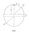
- the perforated plate 45 is shown in plan view in Fig. 5a.
- This perforated plate is formed in the plan view substantially rectangular with two Stimkanten 46 and two longitudinal edges 47. At the longitudinal edges 47 two lugs 48 are formed in each case.
- the lugs 48 engage corresponding slots 49 in the side walls 40 ( Figure 4a).
- the slots 49 are longer than the lugs 48, so that the middle perforated plate 45 is slidably mounted in the direction of its longitudinal edge 47, which define a direction of displacement.
- the middle perforated plate 45 has openings 43 which are formed in substantially the same shape, size and in the same grid as the openings 43 of the upper and lower perforated plates 41, 44.
- the openings of the upper and lower perforated plate 41, 44 are arranged in a straight line projection exactly one above the other.
- the central perforated plate 45 can be moved to a first position, in which the openings of all three perforated plates are arranged exactly one above the other, that is, the corresponding openings of the three perforated plates are aligned with each other.
- the central perforated plate 45 can be moved to a second position in which the openings of which are offset with respect to the openings of the lower and upper perforated plate 41, 44, so that the openings are no longer in alignment with each other.
- the openings 43 are slightly elongated in the direction of displacement and have the shape of two semicircular segments, which are a piece apart.
- the semicircular segments have a radius of 5.6 mm and are moved apart by 1.2 mm.
- a small projection 50 projecting into the region of the opening is formed. This projection is thus arranged at the intersection region between a center line, extending in the direction of displacement, of the opening 43 and the boundary edge of the opening.
- the projections 50 have in plan view only curves and no corners, so they do not perforate the reaction vessels.
- the openings of all three perforated plates 41, 44, 45 have corresponding protrusions 50, the protrusions of the upper and lower perforated plates 41, 44 being diametrically opposed at the openings respectively to the protrusions of the central perforated plate.
- adjusting devices 51 On a front side of the frame 16 two adjusting devices 51 are arranged, with which the middle perforated plate in the direction of displacement between the first and second position can be moved back and forth and fixed in the second position.
- These adjusting devices 51 each have a thumbscrew 52.
- the wing screws 52 have a central bore in which a rod connected to the central perforated plate 45 is supported. This rod has a threaded bore in the longitudinal direction, in which a screw 53 is screwed, which rests with its screw head on the wing screws 52.
- On the side facing the perforated plates side wing screws are each a corresponding stop element 54, which are fixedly connected to the upper and lower perforated plate 41, 44.
- the stop elements 54 are each penetrated by the rod connected to the middle perforated plate.
- the stop elements 54 and the wing screws 52 each have a contact surface 55, 56.
- the surfaces 55, 56 are arranged at an acute angle to a plane perpendicular to the direction of movement.
- a spring element (not shown) is provided, which presses the perforated plate 45 away from the stop elements 54. If the thumbscrews 52 lie with their contact surfaces 55 flat against the contact surfaces 56 of the stop elements 54, then the central perforated plate is in the maximally remote position with respect to the stop elements 54. By means of the screws 53, this position is set such that here the openings 43 of the middle perforated plate 45 to the openings 43 of the upper and lower perforated plate 41, 44 are aligned.
- the oblique contact surfaces cause an offset of the wing screws 52 with respect to the stop elements 54, whereby the middle perforated plate 45 is moved against the spring action of the spring element in the direction of the stop elements 54 and assumes its second position, in the openings 43 of which are offset from the openings of the upper and lower perforated plates 41, 44.
- the contact surfaces 55, 56 are provided with a small latching recess and a corresponding latching projection, so that the wing screws engage the stopper elements 54 when the central perforated plate is in its second position.
- a slider 58 is provided in each case directly above the holes 57.
- the slides 58 each have a slot which is widened at one end corresponding to the holes 57.
- corresponding pins are each provided with a head 60 which pass through the holes 57.
- connections 61 for the tubes 17 are arranged on the end face of the thermoblock 15. In the area between the terminals 61 there is an electrical line 62 to a temperature sensor arranged in the thermoblock 15.
- the frame 16 allows the preparation of a sample row outside the robot 1, wherein a plurality of reaction vessels can be arranged on the frame 16 and fixed thereto.
- the middle perforated plate is in its first position, in which the openings are aligned with the openings of the upper and lower perforated plate.
- the reaction vessels are then manually inserted into the openings 43, for example.
- the openings are dimensioned such that the reaction vessels 13 can not fall through the openings, but rest on the top of the upper perforated plate 41 with a ring web 63 formed on the reaction vessels 13.
- the middle perforated plate 45 is moved to its second position by turning the wing screws 52, wherein the reaction vessels 13 by the offset of the openings 43 of the central perforated plate with respect to the corresponding openings 43 of the upper and lower perforated plate in Rack to be clamped.
- the projections 50 press something into the elastically yielding plastic material of the reaction vessels 13, so that in addition to the clamping frictional engagement, a positive connection between the frame 16 and the reaction vessels 13 is produced.
- the middle and lower perforated plates 45, 44 are preferably arranged on the frame 16 so that they engage a portion 64 of the reaction vessels 13, are formed on the circumferentially vertical ribs.
- the thus stocked frame 16 can be easily handled and fixed on the Rüttelstation 14. It is also possible that the loaded rack may be used in other process steps, such as e.g. an autoclaving is supplied.
- the frame according to the invention fixes a plurality of reaction vessels rotationally and in the vertical direction.
- the frame according to the invention can be used very advantageously in conjunction with the gripper according to the invention, since large forces exerted when sliding the gripper on a lid on the reaction vessels and pulling a gripper from a screwed onto a reaction vessel lid, safely and without problems for the operation can be absorbed by the frame.
- the frame according to the invention is very simple and therefore can be manufactured inexpensively. Another advantage is that commercially available reaction vessels with screwable lid can be used.
- 51 quick-release elements may be provided instead of the adjusting devices 51 described above, as they are known from bicycle hubs.
- the robot it is also possible for the robot to have a plurality of robot arms running on a common horizontal rail.
Abstract
Description
Die Erfindung betrifft eine Vorrichtung zum automatischen Öffnen und Schließen von Reaktionsgefäßen, insbesondere betrifft die Erfindung eine Vorrichtung zum automatischen Öffnen und Schließen von Reaktionsgefäßen mit auf die Reaktionsgefäße schraubbaren Deckel. Die Erfindung soll insbesondere für Anwendungen in einem Roboter zur Durchführung chemischer und/oder biologischer Reaktionen geeignet sein.The invention relates to a device for automatic opening and closing of reaction vessels, in particular the invention relates to a device for automatically opening and closing of reaction vessels with screwed onto the reaction vessel lid. The invention is intended to be particularly suitable for applications in a robot for carrying out chemical and / or biological reactions.
Es sind Vorrichtungen zum automatischen Öffnen und Schließen von Reaktionsgefäßen bekannt, die einen Greifer aufweisen, der zum Greifen eines Deckels betätigbar ist und mit einem Drehmechanismus versehen ist, so dass mittels des Greifers der Deckel auf ein Reaktionsgefäß bzw. von einem Reaktionsgefäß geschraubt werden kann. Die Reaktionsgefäße haben meistens eine spezielle Form, so dass sie formschlüssig in einen entsprechenden Aufnahmebereich in einer Halterung eingreifen. Hierdurch wird eine drehfeste Anordnung des Reaktionsgefäßes sichergestellt.There are devices for automatically opening and closing of reaction vessels are known which have a gripper which is operable to grip a lid and is provided with a rotating mechanism, so that by means of the gripper, the lid can be screwed onto a reaction vessel or from a reaction vessel. The reaction vessels usually have a special shape, so that they engage positively in a corresponding receiving area in a holder. As a result, a rotationally fixed arrangement of the reaction vessel is ensured.
Aus der
Der Erfindung liegt deshalb die Aufgabe zugrunde, eine Vorrichtung zum automatischen Öffnen und Schließen von Reaktionsgefäßen zu schaffen, mit welcher übliche, nicht speziell ausgebildete Reaktionsgefäße sicher mit einem schraubbaren Deckel geöffnet und geschlossen werden können.The invention is therefore based on the object to provide a device for automatically opening and closing of reaction vessels, with which conventional, not specially trained reaction vessels can be safely opened and closed with a screw-lid.
Diese Aufgabe wird durch eine Vorrichtung mit dem Merkmal des Anspruchs 1 gelöst.This object is achieved by a device having the feature of
Vorteilhafte Ausgestaltungen der Erfindung sind in den jeweiligen Unteransprüchen angegeben.Advantageous embodiments of the invention are specified in the respective subclaims.
Die erfindungsgemäße Vorrichtung zum automatischen Öffnen und Schließen von Reaktionsgefäßen umfasst eine Halteeinrichtung zum verdrehsicheren Halten von zumindest einem Reaktionsgefäß, einen Greifer zum Greifen eines Deckels für das Reaktionsgefäß, wobei der Greifer Greifbacken zum Umfassen des Deckels aufweist, und einen Haltearm mit einem Drehmechanismus zum drehbaren Halten des Greifers.
Die erfindungsgemäße Vorrichtung zeichnet sich dadurch aus, dass die Halteeinrichtung drei übereinanderliegend angeordnete Lochplatten aufweist, in welchen Öffnungen zum Aufnehmen der Reaktionsgefäße ausgebildet sind, wobei die obere und die untere Lochplatte ortsfest mit den darin ausgebildeten Öffnungen zueinander fluchtend angeordnet sind, und die mittlere Lochplatte verschieblich zwischen einer ersten Position, in der deren Öffnungen mit den Öffnungen der oberen und unteren Lochplatten fluchten, und einer zweiten Position ausgebildet ist, in der deren Öffnungen zu den Öffnungen der oberen und unteren Lochplatten etwas außer Flucht angeordnet sind, so dass ein in die Öffnungen der Lochplatten eingebrachtes Reaktionsgefäß verdrehsicher geklemmt ist, und dass Mittel zum Fixieren der mittleren Lochplatte in der zweiten Position vorgesehen sind.The apparatus for automatic opening and closing of reaction vessels according to the invention comprises a holding device for non-rotatably holding at least one reaction vessel, a gripper for gripping a lid for the reaction vessel, wherein the gripper has gripping jaws for embracing the lid, and a holding arm with a rotatable mechanism for rotatable holding of the gripper.
The device according to the invention is characterized in that the holding device comprises three perforated plates arranged one above the other, in which openings are formed for receiving the reaction vessels, wherein the upper and lower perforated plates are arranged stationary with the openings formed therein aligned, and the central perforated plate displaceable between a first position in which the openings of which are aligned with the openings of the upper and lower perforated plates, and a second position is formed, in which the openings are arranged slightly out of alignment with the openings of the upper and lower perforated plates, so that in the openings the perforated plates introduced reaction vessel is clamped against rotation, and that means are provided for fixing the central perforated plate in the second position.
Ein oder mehrere Reaktionsgefäße können in entsprechende Öffnungen in den Lochplatten eingebracht werden und durch Verschieben der mittleren Lochplatte in die zweite Position in den Lochplatten verdrehsicher geklemmt werden, wobei durch das Fixieren der mittleren Lochplatte in der zweiten Position die Reaktionsgefäße entsprechend gehalten werden.One or more reaction vessels can be inserted into corresponding openings in the perforated plates and clamped by moving the middle perforated plate in the second position in the perforated plates against rotation, wherein the reaction vessels are held by fixing the middle perforated plate in the second position accordingly.
Bei einer bevorzugten Ausführungsform ist in den Öffnungen der mittleren Lochplatte jeweils ein in den Innenbereich der Öffnung vorstehender Vorsprung ausgebildet, der etwa am Schnittbereich zwischen einer in Verschieberichtung verlaufenden Mittellinie der jeweiligen Öffnung und dem Rand der Öffnung angeordnet ist. Beim Klemmen der Reaktionsgefäße in den Lochplatten wird dieser Vorsprung an die Wandung der Lochplatte gedrückt, so dass eine formschlüssige Halterung der Reaktionsgefäße bewerkstelligt wird.In a preferred embodiment, a projection projecting into the inner region of the opening is formed in the openings of the middle perforated plate, which projection is arranged approximately at the intersection between a center line of the respective opening and the edge of the opening in the direction of displacement. When clamping the reaction vessels in the perforated plates of this projection is pressed against the wall of the perforated plate, so that a positive retention of the reaction vessels is accomplished.
Vorzugsweise sind die obere und/oder untere Lochplatte einer Öffnung jeweils mit entsprechenden Vorsprüngen ausgebildet, die an der Öffnung diametral gegenüber liegend zu den Vorsprüngen der mittleren Lochplatte angeordnet sind. Dies erhöht den Formschluss, mit welcher die Reaktionsgefäße in den Lochplatten gehalten werden.Preferably, the upper and / or lower perforated plate of an opening are each formed with corresponding projections, which are arranged on the opening diametrically opposite to the projections of the central perforated plate. This increases the positive connection with which the reaction vessels are held in the perforated plates.
Vorzugsweise zeichnet sich eine Ausführungsform der Vorrichtung dadurch aus, dass die Greifbacken derart angeordnet sind, dass beim Einführen des Deckels in den Bereich zwischen den Greifbacken dieser von den Greifbacken durch Reibschluss gehalten wird, und der Greifer keine aktive Betätigungseinrichtung zum Öffnen und Schließen der Greifbacken aufweist.Preferably, an embodiment of the device is characterized in that the gripping jaws are arranged such that upon insertion of the lid in the area between the gripping jaws this is held by the jaws frictionally, and the gripper has no active actuator for opening and closing the gripping jaws ,
Der Deckel wird somit im wesentlichen durch den Reibschluss zwischen den Greifbacken und dem Deckel gehalten. Es ist kein zusätzlicher Stellmechanismus zum Betätigen der Greifbacken notwendig und auch nicht vorgesehen. Trotzdem können herkömmliche Deckel mit dem Greifer umgriffen werden, ohne dass die Deckel hierzu besonders ausgestaltet sein müssen.The lid is thus held substantially by the frictional engagement between the gripping jaws and the lid. There is no additional adjusting mechanism for actuating the jaws necessary and not provided. Nevertheless, conventional lids can be grasped with the gripper without the lids having to be specially designed for this purpose.
Aus der Kombination des
- Haltens der Deckel mit Reibschluss, und
- Haltens der Reaktionsgefäße durch Klemmen,
- Hold the lid with frictional engagement, and
- Holding the reaction vessels by clamping,
Durch das klemmende Halten der Reaktionsgefäße ist die Reibungskraft, mit welcher der Greifer auf einen Deckel aufgeschoben wird, alleine durch die mechanischen Eigenschaften der Einrichtung, mit welchen der Greifer bewegt wir, begrenzt. Das klemmende Halten erlaubt somit die Einstellung beträchtlicher Reibungskräfte zum Aufschieben des Greifers.Due to the clamping holding the reaction vessels, the frictional force with which the gripper is pushed onto a lid, limited solely by the mechanical properties of the device with which the gripper moves we. The clamped holding thus allows the setting of considerable frictional forces for pushing the gripper.
Vorzugsweise weisen die Greifbacken an ihren Greifflächen zumindest einen quer zur Drehrichtung verlaufenden Schneidsteg auf. Dieser Schneidsteg besitzt eine scharfe Schneidkante, die an der Oberfläche des Deckels eingreift und so die Übertragung erheblicher Drehmomente vom Greifer auf den Deckel erlaubt.Preferably, the gripping jaws have at least one transverse to the direction of rotation cutting edge on their gripping surfaces. This cutting land has a sharp cutting edge which engages the surface of the lid, thus allowing the transmission of significant torques from the gripper to the lid.
Die Erfindung wird nachfolgend näher anhand der Zeichnung erläutert. In den Zeichnungen zeigen:
- Fig. 1
- einen Roboter mit einer erfindungsgemäßen Vorrichtung zum automatischen Öffnen und Schließen von Reaktionsgefäßen,
- Fig.2a
- einen Greifer in perspektivischer Ansicht,
- Fig. 2b
- den Greifer aus Fig. 2a in einer Schnittansicht,
- Fig. 3a
- einen weiteren Greifer in perspektivischer Ansicht,
- Fig. 3b
- den Greifer aus Fig. 3a in einer Schnittansicht,
- Fig. 4a
- ein erfindungsgemäß ausgebildetes Gestell zum Halten von Reaktionsgefäßen zusammen mit einem Thermoblock und einer Rütteleinrichtung,
- Fig. 4b
- die Anordnung aus Fig. 4a in der der Draufsicht,
- Fig. 4c
- die Anordnung aus Fig. 4a im Teilschnitt,
- Fig. 5a
- eine Lochplatte des Gestells aus Fig. 4a in der Draufsicht,
- Fig. 5b
- eine Öffnung der Lochplatte in vergrößerter Darstellung,
- Fig. 6a
- ein Reaktionsgefäß mit Deckel in einer Seitenansicht, und
- Fig. 6b
- das Reaktionsgefäß und der Deckel aus Fig. 6a in perspektivischer Ansicht.
- Fig. 1
- a robot with a device according to the invention for the automatic opening and closing of reaction vessels,
- 2a
- a gripper in perspective view,
- Fig. 2b
- the gripper of Fig. 2a in a sectional view,
- Fig. 3a
- another gripper in perspective view,
- Fig. 3b
- the gripper of Fig. 3a in a sectional view,
- Fig. 4a
- an inventively designed frame for holding reaction vessels together with a thermoblock and a vibrator,
- Fig. 4b
- the arrangement of Fig. 4a in the plan view,
- Fig. 4c
- the arrangement of Fig. 4a in partial section,
- Fig. 5a
- a perforated plate of the frame of Fig. 4a in plan view,
- Fig. 5b
- an opening of the perforated plate in an enlarged view,
- Fig. 6a
- a reaction vessel with a lid in a side view, and
- Fig. 6b
- the reaction vessel and the lid of Fig. 6a in a perspective view.
Die erfindungsgemäße Vorrichtung zum automatischen Öffnen und Schließen von Reaktionsgefäßen ist zur Anwendung in einem Roboter ausgebildet. Ein solcher Roboter ist schematisch in Fig. 1 dargestellt. Der Roboter 1 weist eine Arbeitsplattform 2, eine Rückwand 3 und einen Roboterarm 4 auf. Der Roboterarm 4 ist entlang einer am oberen Randbereich der Rückwand 3 horizontal angeordneten Schiene (nicht dargestellt) verfahrbar, so dass er den gesamten Bereich der Arbeitsplattform 2 abstreichen kann. Am Roboterarm sind drei Handhabungsarme 5, 6, 7 angeordnet, die sich in vertikaler Richtung erstrecken. Die Handhabungsarme sind auf sich im Roboterarm 4 erstreckenden Schienen (nicht dargestellt) verfahrbar gelagert, so dass sie in Längsrichtung des Roboterarmes 4 verfahrbar sind. Die Handhabungsarme sind auch in vertikaler Richtung verfahrbar. Der Handhabungsarm 5 weist eine Pipettierspitze zum Pipettieren von chemischen und/oder biologischen Reagenzien auf. Der Handhabungsarm 6 ist mit einem gabelförmigen Greifelement 9 versehen, mit welchem Mikrotiterplatten gehandhabt werden können. Der Handhabungsarm 7 weist an seinem unteren Ende einen Drehmechanismus 10 auf, an dem ein Greifer 11 zum Greifen von Deckel 12 für Reaktionsgefäße 13 gekoppelt ist. Der Greifer 11 wird unten näher erläutert.The device according to the invention for the automatic opening and closing of reaction vessels is designed for use in a robot. Such a robot is shown schematically in FIG. The
Auf dem Roboter sind diverse Arbeitsstationen vorgesehen, wobei ein solcher Roboter je nach Bedarf eines Anwenders unterschiedlich konfigurierbar ist. Im vorliegenden Ausführungsbeispiel sind auf der Arbeitsplattform 2 zwei Rüttelstationen mit jeweils einer Rütteleinrichtung14 vorgesehen, an welchen jeweils ein Thermoblock 15 zum Aufnehmen von Reaktionsgefäßen angeordnet ist. Der Thermoblock 15 ist ein quaderförmiger Körper, aus gut wärmeleitendem Material, in dem Kanäle zum Durchleiten eines temperierten Wärmemediums, wie zum Beispiel von Silikonöl, ausgebildet sind. An der oberen Seitenfläche des Thermoblocks 15 sind Ausnehmungen ausgebildet, in welche der untere Bereich der Reaktionsgefäße 13 formschlüssig aufgenommen wird, so dass ein guter Wärmeübergang zwischen dem Thermoblock 15 und den Reaktionsgefäßen hergestellt wird. Auf diesen den Thermoblock 15 aufweisenden Rütteleinrichtungen 14 ist jeweils Gestell 16 angeordnet, das zum Handhaben eines Satzes von Reaktionsgefäßen 13 dient. Dieses Gestell wird unten näher erläutert.Various workstations are provided on the robot, whereby such a robot can be configured differently depending on the needs of a user. In the present embodiment, two vibrating stations, each with a
Der Roboter dieses Ausführungsbeispiels ist zur Direktquantifizierung der RNA des Hepatitis-C Virus (HCV RNA) im Serum oder Plasma HCV-infizierter Personen mittels des VERSANT™ HCV RNA 3.0 Essay (bDNA) beziehungsweise zur Direktquantifizierung der RNA des humanen Immunschwächenvirustyp I (HIV-I) im Plasma mit von HIV-I infizierten Personen mittels des VERSANT™ HIV-I RNA 3.0 Essay (bDNA) vorgesehen. Diesbezüglich wird auf die
Weiterhin weist die Arbeitsplattform 2 einen Vorratsbehälter für Einweg-Pipettenspitzen und einen Behälter für gebrauchte Pipettenspitzen auf. Bei einem solchen Roboter 1 können auch weitere Arbeitsstationen integriert werden, wobei zum Beispiel ein Thermocycler. Bezüglich weiterer Konfigurationen und den allgemeinen Aufbau eines solchen Roboters wird auf die
In Fig. 2a und 2b ist ein erstes Ausführungsbeispiel des Greifers 11 gezeigt. Dieser Greifer 11 weist einen etwa prismenförmigen Grundkörper 18 mit einer regelmäßigen sechseckigen Grundfläche und einer entsprechenden Deckfläche auf. In den Grundkörper 18 sind drei vertikal verlaufende Nuten 19 an jeweils altemierenden Seitenwandungen eingebracht. In jeder Nut 19 lagert jeweils eine Klemmbacke 20, die am Grundkörper 18 ein Stück nach unten vorsteht. Die Greifbacken 20 werden jeweils von einer Achse 21 durchgriffen, die am Grundkörper 18 befestigt sind.In Fig. 2a and 2b, a first embodiment of the
Zwischen den Greifbacken 20 und dem Grundkörper 18 ist jeweils ein Federelement 22 im Bereich unterhalb der Achsen 21 angeordnet, so dass die Greifbacken 20 mit ihren unteren Enden nach außen gedrückt werden. Oberhalb der Achsen 21 ist in den Greifbacken 20 jeweils eine Gewindebohrung eingebracht, in die ein Stellschraube 23 eingeschraubt ist, mit dem der Abstand des unteren Endes der jeweiligen Klemmbacke 20 von einer vertikalen Symmetrieachse 24 einstellbar ist.Between the
An dem unterhalb des Grundkörpers 18 vorstehenden Bereich weisen die Greifbakken 20 jeweils eine zur Symmetrieachse 24 des Greifers 11 weisende Greiffläche 25 auf. Die Greiffläche 25 ist nach oben jeweils durch einen horizontalen Anschlagsteg 26 begrenzt. Am unteren Randbereichbereich der Greiffläche 25 schließt sich ein nach unten und radial nach außen verlaufende Einführschräge 27 an.At the region protruding below the
An den Greifflächen 25 ist jeweils zumindest ein vertikal verlaufender Schneidsteg 28 ausgebildet. Im vorliegenden Ausführungsbeispiel ist auf jeder Greiffläche 25 jeweils ein Schneidsteg 28 vorgesehen. Im Rahmen der Erfindung können jedoch auch mehrere Schneidstege pro Greiffläche ausgebildet sein. Die Höhe, mit der die Schneidstege 28 an der Greiffläche 25 vorstehen, ist kleiner als die Wandstärke eines Reaktionsgefäßes 13 (Fig. 6a, 6b). Im vorliegenden Ausführungsbeispiel beträgt diese Höhe 0,5 mm. Die Schneidstege 28 sind jeweils ausgehend von der Greiffläche 25 spitz zulaufend ausgebildet, so dass sie eine vertikal verlaufende Schneidkante bilden.At least one vertically extending cutting
Die Vorrichtung ist zum Handhaben von Reaktionsgefäßen des Typs "Microtube 1.5 ml" von der Firma Sarstedt vorgesehen, die unter der Artikelbezeichnung SAR-72692 beziehungsweise SAR-62692005 vertrieben werden (www.scimart.com/tubes/screwcap.html).The device is intended for handling microtube 1.5 ml reaction tubes from Sarstedt, sold under article Nos. SAR-72692 and SAR-62692005, respectively (www.scimart.com/tubes/screwcap.html).
An der oberen Deckfläche des Grundkörpers 18 mündet ein mittig angeordnete Sacklochbohrung 29. Der Greifer 11 kann mit der Sacklochbohrung 29 auf einen drehbar angetriebenen Stift des Drehmechanismus 10 aufgeschoben und mittels zweier Fixierschrauben 30 am Drehmechanismus 10 fixiert werden.The
Im Ausgangszustand begrenzen die drei Greifbacken 20 mit ihren Greifflächen 25 einen Bereich, der geringfügig kleiner als der Umfangbereich eines zu greifenden Deckels 12 ist. Der durch die unteren Kanten der Einführschrägen 27 begrenzte Bereich ist etwas größer als der Umfangbereich eines Deckels 12. Wird somit der Greifer 11 auf einen Deckel 12 aufgeschoben, so wird der Deckel etwas elastisch verformt und in den Bereich zwischen den Greifbacken 20 eingeführt, bis er an den Anschlagstegen 26 anliegt. Durch den Reibschluss zwischen den Greifflächen 25 und der Deckelmantelwandung wird der Deckel vom Greifer 11 gehalten, so dass er gehandhabt werden kann. Zusätzlich kerben die Schneidstege 28 die Deckelmantelwandung etwas ein und erzeugen einen Formschluss, wodurch ein erhebliches Drehmoment vom Greifer 11 auf den Deckel 12 übertragen werden kann.In the initial state, the three
Fig. 3a und 3b zeigen ein zweites Ausführungsbeispiel des Greifers 11. Im oberen Bereich weist dieser Greifer 11 einen rohrförmigen Abschnitt 31 auf, in dem zwei Gewindebohrungen zum Einbringen von Fixierschrauben 30 vorgesehen sind, um den Greifer 11 an einem drehbar angetriebenen Stift des Drehmechanismus 10 zu fixieren. Am unteren Ende des rohrförmigen Abschnittes 31 ist ein horizontal verlaufendes Schienenteil 32 ausgebildet. An der Unterseite dieses Schienenteils 32 ist eine schwalbenschwanzförmige Nut 33 ausgebildet.3a and 3b show a second embodiment of the
In der schwalbenschwanzförmigen Nut 33 lagern verschieblich zwei Greifbacken 34, die mittels eines Federelementes 35 derart miteinander verbunden sind, dass die Greifbacken 34 in Richtung zur Symmetrieachse 24 vorgespannt sind. Im Bereich zwischen den beiden Greifbacken 34 ist ein Abstandselement 36 vorgesehen, an dem die Greifbacken 34 im Ausgangszustand, das heißt ohne Deckel, wegen der Vorspannung des Federelementes 35 anliegen.Slidably mounted in the
Die Greifbacken 34 besitzen jeweils einen kreissegmentförmigen Körper, wobei der Kreissegment-Mittelpunkt in der Nähe der Symmetrieachse 24 liegt. Im unteren Drittel ist an der Innenfläche der Greifbacken 34 ein Abschnitt ausgefräst, so dass die Greifbacken 34 in diesem Bereich eine zur Symmetrieachse 24 weisende Greiffläche 37 besitzen, die nach oben durch eine Anschlagstufe 38 begrenzt ist. Am unteren Randbereich der Greifflächen 37 schließt sich jeweils eine nach unten radial nach außen verlaufende Einführschräge 39 an.The jaws 34 each have a circular segment-shaped body, wherein the circle-segment center is in the vicinity of the axis of
An den Greifflächen 37 ist jeweils zumindest ein vertikal verlaufender Schneidsteg 28 ausgebildet. Im vorliegenden Ausführungsbeispiel sind drei Schneidstege pro Greiffläche 37 vorgesehen. Die Ausbildung der Schneidstege entspricht dem ersten Ausführungsbeispiel des Greifers 11.At least one vertically extending cutting
Im Ausgangszustand begrenzen die zwei Greifbacken 34 mit ihren Greifflächen 37 einen Bereich, der etwas kleiner als der Umfangbereich eines zu greifenden Deckels 12 ist. Der durch die unteren Kanten der Einführschrägen 39 begrenzte Bereich ist etwas größer als der Umfangbereich eines Deckels 12. Wird somit der Greifer 11 auf einen Deckel 12 aufgeschoben, so werden entgegen der Federwirkung des Federelementes 35 die Greifbacken 34 durch das Einführen des Deckels 12 an den Einführschrägen 39 auseinandergeschoben und der Deckel in dem Bereich zwischen den Greifbacken 34 eingeführt, bis er an den Anschlagstufen 38 anliegt. Durch einen Reibschluss zwischen den Greifflächen 37 und der Deckelmantelwandung wird der Deckel 12 vom Greifer 11 gehalten, so dass er gehandhabt werden kann. Die Schneidstege 28 erzeugen wiederum einen Formschluss zur Übertragung eines beträchtlichen Drehmomentes.In the initial state, the two gripping jaws 34 with their
Nachfolgend wird das Gestell 16 zum Aufnehmen der Reaktionsgefäße näher erläutert (Fig. 4a, 4b. 4c). Dieses Gestell 16 ist umgekehrt u-förmig ausgebildet mit zwei Seitenwandungen 40 und einer Deckenwandung 41. Die Seitenwandungen sind jeweils nach außen umgebogen, so dass ein schmaler, streifenförmiger Fußabschnitt 42 nach außen vorstehend ausgebildet ist. Die Deckenwandung 41 ist als Lochplatte ausgebildet, wobei in einem regelmäßigen Raster Öffnungen 43 zum Aufnehmen von Reaktionsgefäßen eingebracht sind. Unterhalb der Deckenwandung 41 ist in einem vorbestimmten Abstand, zum Beispiel 5 bis 10 mm, eine weitere Lochplatte, die nachfolgend als untere Lochplatte 44 bezeichnet wird, angeordnet. Die untere Lochplatte 44 ist mit ihren an den Seitenwandungen 40 angrenzenden Randbereichen nach unten gebördelt und die gebördelten Abschnitte sind an den Seitenwandungen 40 beispielsweise durch Löten oder mittels Schraubverbindungen befestigt. Die Dekkenwandung 41, die nachfolgend auch als obere Lochplatte 41 bezeichnet wird, und die untere Lochplatte 44 begrenzen somit einen Zwischenraum, in dem eine weitere Lochplatte 45 angeordnet ist, die im folgenden als mittlere Lochplatte bezeichnet wird.The
Die Lochplatte 45 ist in der Draufsicht in Fig. 5a dargestellt. Diese Lochplatte ist in der Draufsicht im wesentlichen rechteckförmig mit zwei Stimkanten 46 und zwei Längskanten 47 ausgebildet. An den Längskanten 47 sind jeweils zwei Nasen 48 angeformt. Die Nasen 48 greifen in entsprechende Schlitze 49 in den Seitenwandungen 40 (Fig. 4a) ein. Die Schlitze 49 sind länger als die Nasen 48, so dass die mittlere Lochplatte 45 in Richtung ihrer Längskante 47, die eine Verschieberichtung festlegen, verschieblich gelagert ist.The
Auch die mittlere Lochplatte 45 weist Öffnungen 43 auf, die im wesentlichen in der gleichen Form, Größe und im gleichen Raster wie die Öffnungen 43 der oberen und der unteren Lochplatte 41, 44 ausgebildet sind.The middle
Die Öffnungen der oberen und unteren Lochplatte 41, 44 sind in geradliniger Projektion exakt übereinander angeordnet. Die mittlere Lochplatte 45 kann in eine erste Position verschoben werden, in der die Öffnungen aller drei Lochplatten exakt übereinander angeordnet sind, das heißt, die korrespondierenden Öffnungen der drei Lochplatten fluchten zueinander. Die mittlere Lochplatte 45 kann in eine zweite Position verschoben werden, in der deren Öffnungen bezüglich der Öffnungen der unteren und oberen Lochplatte 41, 44 versetzt sind, so dass die Öffnungen nicht mehr in Flucht zueinander sind.The openings of the upper and lower
Die Öffnungen 43 (Fig. 5b) sind in Verschieberichtung etwas gestreckt und weisen die Form von zwei Halbkreissegmenten auf, die ein Stück voneinander entfernt sind. Im vorliegenden Ausführungsbeispiel besitzen die Halbkreissegmente einen Radius von 5,6 mm und sind um 1,2 mm auseinander gerückt. Am Scheitelpunkt eines der beiden Halbkreissegmente ist ein kleiner, in den Bereich der Öffnung vorstehender Vorsprung 50 ausgebildet. Dieser Vorsprung ist somit am Schnittbereich zwischen einer in Verschieberichtung verlaufenden Mittellinie der Öffnung 43 und dem Begrenzungsrand der Öffnung angeordnet. Die Vorsprünge 50 weisen in der Draufsicht nur Rundungen und kein Ecken auf, damit sie die Reaktionsgefäße nicht perforieren.The openings 43 (Fig. 5b) are slightly elongated in the direction of displacement and have the shape of two semicircular segments, which are a piece apart. In the present embodiment, the semicircular segments have a radius of 5.6 mm and are moved apart by 1.2 mm. At the apex of one of the two semicircular segments, a
Die Öffnungen aller drei Lochplatten 41, 44, 45 weisen entsprechende Vorsprünge 50 auf, wobei die Vorsprünge der oberen und unteren Lochplatte 41 ,44 an den Öffnungen jeweils zu den Vorsprüngen der mittleren Lochplatte diametral gegenüberliegend angeordnet sind.The openings of all three
An einer Stirnseite des Gestells 16 sind zwei Stelleinrichtungen 51 angeordnet, mit welchen die mittlere Lochplatte in Verschieberichtung zwischen der ersten und zweiten Position hin und her bewegt werden kann und in der zweiten Position fixiert werden kann. Diese Stelleinrichtungen 51 weisen jeweils eine Flügelschraube 52 auf. Die Flügelschrauben 52 besitzen eine mittige Bohrung, in der eine mit der mittleren Lochplatte 45 verbundene Stange lagert. Diese Stange weist in Längsrichtung eine Gewindebohrung auf, in die eine Schraube 53 eingeschraubt ist, die mit ihrem Schraubenkopf auf den Flügelschrauben 52 aufliegt. An der zu den Lochplatten weisenden Seite liegen die Flügelschrauben an jeweils einem korrespondierenden Anschlagelement 54 an, die mit der oberen und unteren Lochplatte 41, 44 fest verbunden sind. Die Anschlagelemente 54 werden jeweils von der mit der mittleren Lochplatte verbundenen Stange durchgriffen. Die Anschlagelemente 54 und die Flügelschrauben 52 weisen jeweils eine Kontaktfläche 55, 56 auf.On a front side of the
Die Flächen 55, 56 sind in einem spitzen Winkel zu einer zur Bewegungsrichtung senkrecht angeordneten Ebene angeordnet. Zwischen den Anschlagelementen 54 und der mittleren Lochplatte 45 ist ein Federelement (nicht dargestellt) vorgesehen, das die Lochplatte 45 weg von den Anschlagelementen 54 drückt. Liegen die Flügelschrauben 52 mit ihren Kontaktflächen 55 flächig an den Kontaktflächen 56 der Anschlagelemente 54 an, so befindet sich die mittlere Lochplatte in der maximal entfernten Position bezüglich der Anschlagelemente 54. Mittels der Schrauben 53 wird diese Position derart eingestellt, dass hier die Öffnungen 43 der mittleren Lochplatte 45 zu den Öffnungen 43 der oberen und unteren Lochplatte 41, 44 fluchten. Werden nun die Flügelschrauben 52 um 180° gedreht, so bewirken die schrägen Kontaktflächen einen Versatz der Flügelschrauben 52 bezüglich der Anschlagelemente 54, wodurch die mittlere Lochplatte 45 entgegen der Federwirkung des Federelementes in Richtung zu den Anschlagelementen 54 bewegt wird und ihre zweite Position einnimmt, in der deren Öffnungen 43 versetzt zu den Öffnungen der oberen und unteren Lochplatte 41, 44 sind. Die Kontaktflächen 55, 56 sind mit einer kleinen Rastausnehmung und einem korrespondierenden Rastvorsprung versehen, so dass die Flügelschrauben an den Anschlagelementen 54 einrasten, wenn sich die mittlere Lochplatte in ihrer zweiten Position befindet.The
An den beiden Fußabschnitten 42 sind jeweils vier Löcher 57 ausgebildet. An einem der beiden Fußabschnitte sind im Bereich unmittelbar über den Löchern 57 jeweils ein Schieber 58 vorgesehen. Die Schieber 58 weisen jeweils ein Langloch auf, das an einem Ende entsprechend den Löchern 57 aufgeweitet ist. An der Rüttelstation 14 sind korrespondierende Stifte mit jeweils einem Kopf 60 vorgesehen, die durch die Löcher 57 passen. Beim Aufsetzen des Gestells 16 auf die Rüttelstation 14 werden die Köpfe 60 durch die Löcher 57 und den erweiterten Bereich der Langlöcher 59 hindurchgeführt und danach werden die Schieber 58 derart verschoben, dass der schmälere Bereich der Langlöcher 59 die Köpfe 60 hintergreift und das Gestell auf der Rüttelstation 14 fixiert ist. Die Löcher 57 des anderen Fußabschnittes 42 werden von entsprechend hakenförmigen Elementen durchgriffen, die an der Rüttelstation 14 ausgebildet sind. Hierdurch wird das Gestell 16 auf der Rüttelstation 14 derart fixiert, dass es auch bei den von der Rüttelstation ausgeführten Rüttelbewegungen sicher an der Rüttelstation gehalten wird.At the two
Bei der in den Figuren 4a und 4b dargestellten Ausführungsform sind Anschlüsse 61 für die Schläuche 17 an der Stirnfläche des Thermoblocks 15 angeordnet. Im Bereich zwischen den Anschlüssen 61 befindet sich eine elektrische Leitung 62 zu einem im Thermoblock 15 angeordneten Temperatursensor.In the embodiment illustrated in FIGS. 4 a and 4 b,
Das erfindungsgemäße Gestell 16 erlaubt die Vorbereitung einer Probenreihe außerhalb der Roboters 1, wobei eine Vielzahl von Reaktionsgefäßen am Gestell 16 angeordnet und daran fixiert werden können. Hierbei befindet sich die mittlere Lochplatte in ihrer ersten Position, in der deren Öffnungen mit den Öffnungen der oberen und unteren Lochplatte fluchten. Die Reaktionsgefäße werden dann zum Beispiel manuell in die Öffnungen 43 eingeführt. Die Öffnungen sind so bemessen, dass die Reaktionsgefäße 13 nicht durch die Öffnungen hindurch fallen können, sondern mit einem an den Reaktionsgefäßen 13 ausgebildeten Ringsteg 63 an der Oberseite der oberen Lochplatte 41 aufliegen. Sind alle Reaktionsgefäße 13 im Gestell 16 angeordnet, so wird die mittlere Lochplatte 45 in ihre zweite Position durch Drehen der Flügelschrauben 52 verbracht, wobei die Reaktionsgefäße 13 durch den Versatz der Öffnungen 43 der mittleren Lochplatte bezüglich der korrespondierenden Öffnungen 43 der oberen und unteren Lochplatte im Gestell festgeklemmt werden. Insbesondere drücken die Vorsprünge 50 sich etwas in das elastisch nachgebende Kunststoffmaterial der Reaktionsgefäße 13 ein, so dass neben dem klemmenden Reibschluss auch ein Formschluss zwischen dem Gestell 16 und den Reaktionsgefäßen 13 hergestellt wird. Die mittlere und untere Lochplatte 45, 44 sind vorzugsweise derart am Gestell 16 angeordnet, dass sie an einem Abschnitt 64 der Reaktionsgefäße 13 angreifen, an dem umlaufend vertikal verlaufende Rippen ausgebildet sind.The
Das derart bestückte Gestell 16 kann einfach gehandhabt werden und auf der Rüttelstation 14 fixiert werden. Es ist auch möglich, dass das bestückte Gestell anderen Prozessschritten, wie z.B. einer Autoklavierung, zugeführt wird.The thus stocked
Das erfindungsgemäße Gestell fixiert eine Vielzahl von Reaktionsgefäßen verdrehfest und in vertikaler Richtung. Hierdurch ist das erfindungsgemäße Gestell sehr vorteilhaft in Verbindung mit dem erfindungsgemäßen Greifer einsetzbar, da große Kräfte, die beim Aufschieben des Greifers auf einen Deckel auf die Reaktionsgefäße und beim Abziehen eines Greifers von einem auf ein Reaktionsgefäß geschraubten Deckel ausgeübt werden, sicher und ohne Probleme für den Betrieb vom Gestell aufgenommen werden.The frame according to the invention fixes a plurality of reaction vessels rotationally and in the vertical direction. As a result, the frame according to the invention can be used very advantageously in conjunction with the gripper according to the invention, since large forces exerted when sliding the gripper on a lid on the reaction vessels and pulling a gripper from a screwed onto a reaction vessel lid, safely and without problems for the operation can be absorbed by the frame.
Zudem ist das erfindungsgemäße Gestell sehr einfach ausgebildet und kann deshalb kostengünstig hergestellt werden. Ein weiterer Vorteil liegt darin, dass handelsübliche Reaktionsgefäße mit schraubbaren Deckel verwendet werden können.In addition, the frame according to the invention is very simple and therefore can be manufactured inexpensively. Another advantage is that commercially available reaction vessels with screwable lid can be used.
Die Erfindung ist oben anhand eines Ausführungsbeispiels erläutert. im Rahmen der Erfindung ist es auch möglich, dass anstelle der drei Stellschrauben 23 des Greifers 11 nach dem ersten Ausführungsbeispiel im Bodenbereich des Sackloches 29 ein konischer Kegel vorgesehen ist, an dessen Kegelfläche die Greifbacken mit ihrem oberen Bereich anliegen. Der Kegel ist an einer Gewindestange angeordnet, die im Greifer in einer vertikalen Gewindebohrung lagert. Durch Drehen der Gewindestange wird die vertikale Position des Kegels verändert und die Greifbacken um die Achsen 21 geschwenkt, wodurch der Aufnahmebereich justiert wird.The invention is explained above with reference to an embodiment. in the context of the invention it is also possible that instead of the three adjusting
Gemäß einer weiteren Abwandlung der Erfindung können anstelle der oben beschriebenen Stelleinrichtungen 51 Schnellspannelemente vorgesehen werden, wie sie von Fahrradnaben bekannt sind.According to a further modification of the invention, 51 quick-release elements may be provided instead of the adjusting
Im Rahmen der Erfindung ist es auch möglich, dass der Roboter mehrere auf einer gemeinsamen horizontalen Schiene verlaufende Roboterarme aufweist.Within the scope of the invention, it is also possible for the robot to have a plurality of robot arms running on a common horizontal rail.
- 11
- Roboterrobot
- 22
- Arbeitsplattformworking platform
- 33
- Rückwandrear wall
- 44
- Roboterarmrobot arm
- 55
- Handhabungsarmhandling arm
- 66
- Handhabungsarmhandling arm
- 77
- Handhabungsarmhandling arm
- 88th
- Pipettierspitzepipette tip
- 99
- Greifelementgripping element
- 1010
- Drehmechanismusrotating mechanism
- 1111
- Greifergrab
- 1212
- Deckelcover
- 1313
- Reaktionsgefäßreaction vessel
- 1414
- Rüttelstationvibrating station
- 1515
- Thermoblockthermoblock
- 1616
- Gestellframe
- 1717
- Schläuchehoses
- 1818
- Grundkörperbody
- 1919
- Nutengroove
- 2020
- Greifbackejaw
- 2121
- Achseaxis
- 2222
- Federelementspring element
- 2323
- Stellschraubescrew
- 2424
- Symmetrieachseaxis of symmetry
- 2525
- Greifflächegripping surface
- 2626
- Anschlagstegstop web
- 2727
- Einführschrägechamfer
- 2828
- Schneidstegcutting bridge
- 2929
- SacklochbohrungBlind hole
- 3030
- Fixierschraubefixing screw
- 3131
- rohrförmiger Abschnitttubular section
- 3232
- Schienenteilrail part
- 3333
- Nutgroove
- 3434
- Greifbackenjaws
- 3535
- Federelementspring element
- 3636
- Abstandselementspacer
- 3737
- Greifflächegripping surface
- 3838
- Anschlagstufestop step
- 3939
- Einführschrägechamfer
- 4040
- Seitenwandungsidewall
- 4141
- Deckenwandungtop wall
- 4242
- Fußabschnittfoot section
- 4343
- Öffnungopening
- 4444
- untere Lochplattelower perforated plate
- 4545
- mittlere Lochplattemiddle perforated plate
- 4646
- Stimkanteend edge
- 4747
- Längskantelongitudinal edge
- 4848
- Nasenose
- 4949
- Schlitzslot
- 5050
- Vorsprunghead Start
- 5151
- Stelleinrichtungsetting device
- 5252
- Flügelschraubethumbscrew
- 5353
- Schraubescrew
- 5454
- Anschlagelementstop element
- 5555
- Kontaktflächecontact area
- 5656
- Kontaktflächecontact area
- 5757
- Lochhole
- 5858
- Schieberpusher
- 5959
- LanglochLong hole
- 6060
- Kopfhead
- 6161
- Anschlussconnection
- 6262
- Leitungmanagement
Claims (13)
dass die Halteeinrichtung (16) drei übereinanderliegend angeordnete Lochplatten (41, 44, 45) aufweist, in welchen Öffnungen (43) zum Aufnehmen der Reaktionsgefäße (13) ausgebildet sind, wobei die obere und die untere Lochplatte (41, 44) ortsfest mit den darin ausgebildeten Öffnungen (43) zueinander fluchtend angeordnet sind, und die mittlere Lochplatte (45) verschieblich zwischen einer ersten Position, in der deren Öffnungen (43) mit den Öffnungen (43) der weiteren Lochplatten fluchten, und einer zweiten Position angeordnet ist, in der deren Öffnungen (43) zu den Öffnungen (43) der weiteren Lochplatten etwas versetzt angeordnet sind, so dass ein in die Öffnungen (43) der Lochplatten (41, 44, 45) eingebrachtes Reaktionsgefäß (13) geklemmt ist, und
dass Mittel (51) zum Fixieren der mittleren Lochplatte (45) in der zweiten Position vorgesehen sind.Device for automatic opening and closing of reaction vessels, comprising
in that the holding device (16) has three perforated plates (41, 44, 45) arranged one above the other in which openings (43) are formed for receiving the reaction vessels (13), the upper and the lower perforated plates (41, 44) being stationary with the formed therein openings (43) are mutually aligned, and the central perforated plate (45) displaceable between a first position in which the openings (43) are aligned with the openings (43) of the further perforated plates, and a second position is arranged in the openings (43) of which are arranged offset somewhat to the openings (43) of the further perforated plates, so that a reaction vessel (13) introduced into the openings (43) of the perforated plates (41, 44, 45) is clamped, and
in that means (51) are provided for fixing the central perforated plate (45) in the second position.
dadurch gekennzeichnet,
dass die mittlere Lochplatte (45) nur in eine Richtung, der Verschieberichtung, verschieblich gelagert ist.Device according to claim 1,
characterized,
is displaceably mounted in one direction only, the direction of displacement that the middle perforated plate (45).
dadurch gekennzeichnet,
dass die Öffnungen (43) in Verschieberichtung eine größere Weite aufweisen als quer zur Verschieberichtung.Device according to claim 2,
characterized,
that the openings (43) in the direction of displacement have a greater width than transversely to the direction of displacement.
dadurch gekennzeichnet,
dass an der mittleren Lochplatte (45) an den Öffnungen (43) jeweils ein in den Innenbereich der Öffnungen (43) vorstehender Vorsprung (50) ausgebildet ist, der am Schnittbereich zwischen einer in Verschieberichtung verlaufenden Mittellinie der jeweiligen Öffnung (43) und dem Rand der Öffnung (43) angeordnet ist.Device according to claim 2 or 3,
characterized,
in that a projection (50) projecting into the inner region of the openings (43) is formed on the middle perforated plate (45) at the openings (43), which is located at the intersection between a center line of the respective opening (43) running in the direction of displacement and the edge the opening (43) is arranged.
dadurch gekennzeichnet,
dass an der oberen und/oder unteren Lochplatte (41, 44) an den Öffnungen (43) jeweils ein in den Innenbereich der Öffnungen (43) vorstehender Vorsprung (50) ausgebildet ist, der zu den Vorsprüngen (50) der mittleren Lochplatte (45) diametral gegenüberliegend angeordnet ist.Device according to claim 4,
characterized,
in that a projection (50) projecting into the inner region of the openings (43) is formed on the upper and / or lower perforated plate (41, 44) at the openings (43), which projection projects to the projections (50) of the central perforated plate (45 ) is arranged diametrically opposite one another.
dadurch gekennzeichnet,
dass Mittel zum Bewegen und Fixieren (51) der mittleren Lochplatte (45) in der zweiten Position vorgesehen sind.Device according to one of claims 1 to 5,
characterized,
in that means for moving and fixing (51) the central perforated plate (45) in the second position are provided.
: dadurch gekennzeichnet,
ass die Greifbacken (20, 34) derart angeordnet sind, dass beim Einführen des Dekkels (12) in den Bereich zwischen den Greifbacken (20, 34) dieser von den Greifbakken (20, 34) durch Reibschluss gehalten wird, und der Greifer (11) keine aktive Betätigungseinrichtung zum Öffnen und Schließen der Greifbacken (20, 34) aufweistDevice according to one of claims 1 to 6,
: characterized
the gripping jaws (20, 34) are arranged in such a way that when the cover (12) is inserted into the area between the gripping jaws (20, 34) it is held in a frictional engagement by the gripper jaws (20, 34), and the gripper (11 ) has no active actuator for opening and closing the jaws (20, 34)
dadurch gekennzeichnet,
dass die Greifbacken (20, 34) Einführschrägen (27, 39) aufweisen.Device according to claim 7,
characterized,
that the gripping jaws (20, 34) lead in chamfer (27, 39).
dadurch gekennzeichnet,
dass die Greifbacken (20, 34) an ihren Greifflächen (25, 37) zumindest einen quer zur Drehrichtung verlaufenden Schneidsteg (28) aufweisen.Device according to claim 7,
characterized,
that the gripping jaws (20, 34) have on their gripping surfaces (25, 37) at least one transverse to the direction of rotation of the cutting web (28).
dadurch gekennzeichnet,
dass die Höhe mit der der Schneidsteg (28) an der Greiffläche (25, 37) vorsteht kleiner als die Wandstärke der Reaktionsgefäße (13) ist und vorzugsweise nicht größer als 0,5 mm ist.Device according to claim 9,
characterized,
that the height of the cutting web (28) on the gripping surface (25, 37) protrude less than the wall thickness of the reaction vessels (13) and preferably not greater than 0.5 mm.
dadurch gekennzeichnet,
dass die Halteeinrichtung (16) einen Klemmmechanismus zum klemmenden Halten von Reaktionsgefäßen (13) aufweist.Device according to one of claims 1 to 10,
characterized,
that the holding device (16) comprises a clamping mechanism for clampingly holding of reaction vessels (13).
dadurch gekennzeichnet,
dass auf der Arbeitsplattform eine Aufnahme zum verdrehsicheren Aufnehmen der Halteeinrichtung (16), bspw. Mittels einer Fixiereinrichtung, vorgesehen ist.Robot according to claim 11,
characterized,
that on the work platform, a receptacle for the rotationally secure receiving the holding device (16), for example. By means of a fixing device, is provided.
Applications Claiming Priority (2)
| Application Number | Priority Date | Filing Date | Title |
|---|---|---|---|
| DE20310332U DE20310332U1 (en) | 2003-07-04 | 2003-07-04 | Device for automatic opening and closing of reaction vessels |
| EP04763068A EP1641705B1 (en) | 2003-07-04 | 2004-07-01 | Device for the automatic opening and closing of reaction vessels |
Related Parent Applications (1)
| Application Number | Title | Priority Date | Filing Date |
|---|---|---|---|
| EP04763068A Division EP1641705B1 (en) | 2003-07-04 | 2004-07-01 | Device for the automatic opening and closing of reaction vessels |
Publications (3)
| Publication Number | Publication Date |
|---|---|
| EP1705149A2 true EP1705149A2 (en) | 2006-09-27 |
| EP1705149A3 EP1705149A3 (en) | 2006-10-04 |
| EP1705149B1 EP1705149B1 (en) | 2008-12-24 |
Family
ID=33441920
Family Applications (2)
| Application Number | Title | Priority Date | Filing Date |
|---|---|---|---|
| EP04763068A Active EP1641705B1 (en) | 2003-07-04 | 2004-07-01 | Device for the automatic opening and closing of reaction vessels |
| EP06014143A Active EP1705149B1 (en) | 2003-07-04 | 2004-07-01 | Device for automatic opening and closing of reaction vessels |
Family Applications Before (1)
| Application Number | Title | Priority Date | Filing Date |
|---|---|---|---|
| EP04763068A Active EP1641705B1 (en) | 2003-07-04 | 2004-07-01 | Device for the automatic opening and closing of reaction vessels |
Country Status (7)
| Country | Link |
|---|---|
| US (1) | US7972579B2 (en) |
| EP (2) | EP1641705B1 (en) |
| JP (1) | JP4414430B2 (en) |
| AT (2) | ATE356778T1 (en) |
| DE (3) | DE20310332U1 (en) |
| ES (2) | ES2282886T3 (en) |
| WO (1) | WO2005002728A2 (en) |
Cited By (3)
| Publication number | Priority date | Publication date | Assignee | Title |
|---|---|---|---|---|
| WO2010054799A1 (en) * | 2008-11-14 | 2010-05-20 | Pvt Probenverteiltechnik Gmbh | Rack device for a sample distribution system |
| US7972579B2 (en) | 2003-07-04 | 2011-07-05 | F. Hoffmann-La Roche Ag | Device for the automatic opening and closing of reaction vessels |
| EP2886508A1 (en) * | 2013-12-20 | 2015-06-24 | CTC Analytics AG | Actuating device for screw-on cap |
Families Citing this family (24)
| Publication number | Priority date | Publication date | Assignee | Title |
|---|---|---|---|---|
| EP2031407B1 (en) * | 2007-08-29 | 2012-06-06 | F. Hoffmann-La Roche AG | Decapping system |
| ES2807324T3 (en) * | 2008-11-14 | 2021-02-22 | Becton Dickinson Co | Universal container capper / uncapper |
| ES2371983B1 (en) * | 2009-09-25 | 2012-11-19 | Sener Ingeniería Y Sistemas, S.A. | DEVICE AND PROCEDURE FOR THE PROCESSING OF BIOLOGICAL SAMPLES. |
| EP2538225A1 (en) * | 2011-06-20 | 2012-12-26 | F. Hoffmann-La Roche AG | System for processing closed sample tubes |
| EP2538227B1 (en) * | 2011-06-20 | 2015-02-18 | F. Hoffmann-La Roche AG | Device for decapping and recapping sample tubes |
| EP2546655B1 (en) | 2011-07-13 | 2019-12-04 | F. Hoffmann-La Roche AG | Instrument and process for the automated processing of liquid samples |
| DE102012103898A1 (en) * | 2012-05-03 | 2013-11-07 | Schott Ag | Supporting structure for simultaneously holding a plurality of medical or pharmaceutical containers and transport or packaging container with self |
| EP2882677B1 (en) * | 2012-08-07 | 2018-12-26 | Cedrex A/S | Test tube capping and de-capping apparatus and method |
| KR101240235B1 (en) * | 2012-11-02 | 2013-03-07 | 기성엠앤이 (주) | Automatic liquid filling machine |
| DE102013200193A1 (en) | 2013-01-09 | 2014-07-10 | Hamilton Bonaduz Ag | Sample processing system with dosing device and thermocycler |
| US20140290181A1 (en) * | 2013-04-01 | 2014-10-02 | Bottle Tree Water Corporation | System and Method for Eco-Friendly Beverage Dispensing Kiosk |
| CN106536371B (en) | 2014-07-16 | 2019-05-07 | 合成基因组股份有限公司 | Lid mechanism |
| CN105879951A (en) * | 2014-12-19 | 2016-08-24 | 贵州省黎平县黔香园油脂有限公司 | Test-tube taking and placing device |
| JP6413972B2 (en) * | 2015-07-31 | 2018-10-31 | 株式会社安川電機 | Sample processing method and sample processing system |
| EP3368465A1 (en) * | 2015-10-27 | 2018-09-05 | Hamilton Storage Technologies, Inc. | Automated bit exchange for laboratory sample tube capping and decapping machines |
| CA3197270A1 (en) | 2016-02-17 | 2017-08-24 | Becton, Dickinson And Company | Automated sample preparation system for diagnostic testing of same |
| CN207067156U (en) | 2016-04-22 | 2018-03-02 | 贝克顿·迪金森公司 | automated diagnostic analyzer |
| CN109073664B (en) * | 2016-04-22 | 2022-12-06 | 贝克顿·迪金森公司 | Automated diagnostic analyzer and method of operating the same |
| US11061044B2 (en) | 2016-08-03 | 2021-07-13 | Hitachi High-Tech Corporation | Plug processing device and specimen test automation system including same |
| JP2018128260A (en) * | 2017-02-06 | 2018-08-16 | 日清食品ホールディングス株式会社 | Automatic pretreatment apparatus for test specimen |
| JP7333569B2 (en) | 2017-02-06 | 2023-08-25 | 日清食品ホールディングス株式会社 | Automatic pretreatment device for test samples |
| US11858796B2 (en) | 2018-04-19 | 2024-01-02 | Bd Kiestra B.V. | Capper/decapper system and method |
| CN109939758A (en) * | 2019-03-28 | 2019-06-28 | 上海市嘉定区中心医院 | A kind of automatic blood pre-treatment of hemorheology detection and liquid relief platform |
| EP4312028A1 (en) * | 2022-07-29 | 2024-01-31 | F. Hoffmann-La Roche AG | Sample vessel closure method, movable cap gripper and sample vessel closure system for automatically closing an open end of a sample vessel with a closure cap |
Citations (6)
| Publication number | Priority date | Publication date | Assignee | Title |
|---|---|---|---|---|
| US4674340A (en) * | 1986-01-21 | 1987-06-23 | Adolph Coors Company | System for determining the torque required to loosen a threaded cap |
| US5533407A (en) * | 1993-10-14 | 1996-07-09 | Compagnie Generale Des Matieres Nucleaires | Assembly for taking liquid samples in jugs sealed by screw gaps |
| US6132684A (en) * | 1997-10-31 | 2000-10-17 | Becton Dickinson And Company | Sample tube holder |
| US6216340B1 (en) * | 1997-10-02 | 2001-04-17 | Roche Diagnostics Corporation | Automatic handling of sample cups closed with a screwable cap |
| US20020014443A1 (en) * | 2000-05-19 | 2002-02-07 | Hansen Timothy Roy | System and method for manipulating magnetically responsive particles fluid samples to collect DNA or RNA from a sample |
| US20030118487A1 (en) * | 2001-10-19 | 2003-06-26 | Monogen, Inc. | Article handling system and method |
Family Cites Families (17)
| Publication number | Priority date | Publication date | Assignee | Title |
|---|---|---|---|---|
| JPS626171A (en) * | 1985-07-03 | 1987-01-13 | Toa Medical Electronics Co Ltd | Plug attaching/detaching device for sample container |
| DE3538971C2 (en) * | 1985-11-02 | 1995-05-24 | Festo Kg | Device for applying and / or removing a screw cap on or from a container |
| US4868105A (en) | 1985-12-11 | 1989-09-19 | Chiron Corporation | Solution phase nucleic acid sandwich assay |
| DE4102479A1 (en) * | 1991-01-29 | 1992-07-30 | Kodak Ag | DEVICE FOR REMOVING PLUGS FROM CONTAINERS WITH A LIQUID |
| JPH05264418A (en) * | 1992-03-16 | 1993-10-12 | Aoyagi Kogyo Kk | Cap opening device for vacuum blood collecting tube |
| US5681697A (en) * | 1993-12-08 | 1997-10-28 | Chiron Corporation | Solution phase nucleic acid sandwich assays having reduced background noise and kits therefor |
| DE19521924C2 (en) * | 1994-06-24 | 1999-08-05 | Lange Gmbh Dr Bruno | Screw cap for a vessel and device for automatically closing the vessel |
| US5681702A (en) * | 1994-08-30 | 1997-10-28 | Chiron Corporation | Reduction of nonspecific hybridization by using novel base-pairing schemes |
| DE19512905A1 (en) * | 1995-04-06 | 1996-10-10 | Boehringer Mannheim Gmbh | Device for pulling or unscrewing closures from vessels |
| JPH09243643A (en) * | 1996-03-11 | 1997-09-19 | Hitachi Ltd | Automatic unstopping device for seal stopper |
| JP3914291B2 (en) | 1996-11-18 | 2007-05-16 | サッポロビール株式会社 | Cap jig |
| DE29720432U1 (en) | 1997-11-19 | 1999-03-25 | Mwg Biotech Gmbh | robot |
| US6257091B1 (en) * | 1998-07-14 | 2001-07-10 | Bayer Corporation | Automatic decapper |
| JP2002068376A (en) | 2000-09-04 | 2002-03-08 | Shimooka Kogyo:Kk | Cap remover |
| JP3752170B2 (en) * | 2001-09-20 | 2006-03-08 | アロカ株式会社 | Handling device |
| JP3973506B2 (en) * | 2002-07-19 | 2007-09-12 | 三洋電機株式会社 | Wireless receiving apparatus, wireless receiving method, and wireless receiving program |
| DE20310332U1 (en) | 2003-07-04 | 2004-11-11 | Mwg-Biotech Ag | Device for automatic opening and closing of reaction vessels |
-
2003
- 2003-07-04 DE DE20310332U patent/DE20310332U1/en not_active Expired - Lifetime
-
2004
- 2004-07-01 AT AT04763068T patent/ATE356778T1/en active
- 2004-07-01 JP JP2006516090A patent/JP4414430B2/en active Active
- 2004-07-01 US US10/561,424 patent/US7972579B2/en active Active
- 2004-07-01 EP EP04763068A patent/EP1641705B1/en active Active
- 2004-07-01 ES ES04763068T patent/ES2282886T3/en active Active
- 2004-07-01 DE DE502004003223T patent/DE502004003223D1/en active Active
- 2004-07-01 EP EP06014143A patent/EP1705149B1/en active Active
- 2004-07-01 DE DE502004008748T patent/DE502004008748D1/en active Active
- 2004-07-01 ES ES06014143T patent/ES2318623T3/en active Active
- 2004-07-01 WO PCT/EP2004/007179 patent/WO2005002728A2/en active IP Right Grant
- 2004-07-01 AT AT06014143T patent/ATE418522T1/en active
Patent Citations (6)
| Publication number | Priority date | Publication date | Assignee | Title |
|---|---|---|---|---|
| US4674340A (en) * | 1986-01-21 | 1987-06-23 | Adolph Coors Company | System for determining the torque required to loosen a threaded cap |
| US5533407A (en) * | 1993-10-14 | 1996-07-09 | Compagnie Generale Des Matieres Nucleaires | Assembly for taking liquid samples in jugs sealed by screw gaps |
| US6216340B1 (en) * | 1997-10-02 | 2001-04-17 | Roche Diagnostics Corporation | Automatic handling of sample cups closed with a screwable cap |
| US6132684A (en) * | 1997-10-31 | 2000-10-17 | Becton Dickinson And Company | Sample tube holder |
| US20020014443A1 (en) * | 2000-05-19 | 2002-02-07 | Hansen Timothy Roy | System and method for manipulating magnetically responsive particles fluid samples to collect DNA or RNA from a sample |
| US20030118487A1 (en) * | 2001-10-19 | 2003-06-26 | Monogen, Inc. | Article handling system and method |
Cited By (5)
| Publication number | Priority date | Publication date | Assignee | Title |
|---|---|---|---|---|
| US7972579B2 (en) | 2003-07-04 | 2011-07-05 | F. Hoffmann-La Roche Ag | Device for the automatic opening and closing of reaction vessels |
| WO2010054799A1 (en) * | 2008-11-14 | 2010-05-20 | Pvt Probenverteiltechnik Gmbh | Rack device for a sample distribution system |
| US8940252B2 (en) | 2008-11-14 | 2015-01-27 | Roche Diagnostics Operations, Inc. | Rack apparatus for a sample distribution system |
| EP2886508A1 (en) * | 2013-12-20 | 2015-06-24 | CTC Analytics AG | Actuating device for screw-on cap |
| US10494243B2 (en) | 2013-12-20 | 2019-12-03 | Ctc Analytics Ag | Activating device for screw caps |
Also Published As
| Publication number | Publication date |
|---|---|
| ATE418522T1 (en) | 2009-01-15 |
| ATE356778T1 (en) | 2007-04-15 |
| JP2007526983A (en) | 2007-09-20 |
| WO2005002728A3 (en) | 2005-07-21 |
| WO2005002728A2 (en) | 2005-01-13 |
| DE502004008748D1 (en) | 2009-02-05 |
| JP4414430B2 (en) | 2010-02-10 |
| US20070098597A1 (en) | 2007-05-03 |
| EP1705149B1 (en) | 2008-12-24 |
| US7972579B2 (en) | 2011-07-05 |
| ES2318623T3 (en) | 2009-05-01 |
| EP1705149A3 (en) | 2006-10-04 |
| EP1641705B1 (en) | 2007-03-14 |
| ES2282886T3 (en) | 2007-10-16 |
| DE502004003223D1 (en) | 2007-04-26 |
| DE20310332U1 (en) | 2004-11-11 |
| EP1641705A2 (en) | 2006-04-05 |
Similar Documents
| Publication | Publication Date | Title |
|---|---|---|
| EP1705149B1 (en) | Device for automatic opening and closing of reaction vessels | |
| EP3478418B1 (en) | Metering head, metering device comprising a metering head, and method for metering by means of a metering head | |
| DE102009013778B4 (en) | Positioning device for a sample carrier | |
| EP3083053B1 (en) | Covering device, in particular lid, for covering reaction vessels | |
| DE69835325T2 (en) | Automatic handling of sample containers enclosed with a removable cap | |
| EP2547431B1 (en) | Positioning unit for a functional unit | |
| EP1407861B1 (en) | Gripping tool, dosing tool and tool holder for laboratory analyzer | |
| EP3479129B1 (en) | Metering head, metering device comprising a metering head, and method for metering by means of a metering head | |
| DE102005023203B4 (en) | pipette | |
| DE10308362A1 (en) | System for automatic opening of test tubes | |
| EP3632568B1 (en) | Device for the thermal treatment of samples | |
| EP0299141B1 (en) | Machine tool, punching machine or suchlike machine with a tool holding device for automatic tool changing | |
| EP3666379A1 (en) | Pipetting head, pipette device comprising a pipetting head and method for pipetting by means of a pipetting head | |
| DE60125038T2 (en) | DEVICE AND METHOD FOR TRANSPORTING TITLE PLATES | |
| EP3632569B1 (en) | Temperature control block module and device for thermal processing of samples | |
| EP2566613B1 (en) | Connection for a temperature-controllable exchangeable block | |
| DE102004016154B4 (en) | Quick adjustable pliers | |
| EP2578317B1 (en) | Manual metering device | |
| DE19501298C1 (en) | Fitting of micro-dishes into and removal from carrier | |
| EP3826757B1 (en) | Mixing apparatus | |
| DE10011479A1 (en) | Clamping arrangement has basic body with inner passage, bar with lower end. fixture elements, clamping elements and pressure elements | |
| AT394804B (en) | HOLDING DEVICE, IN PARTICULAR FOR THE HOUSEHOLD AND KITCHEN AREA | |
| EP4169618A1 (en) | Specimen container handling system | |
| DD289221A5 (en) | CYTOBACCO FOR CYTOZENTRIFUGATION |
Legal Events
| Date | Code | Title | Description |
|---|---|---|---|
| PUAI | Public reference made under article 153(3) epc to a published international application that has entered the european phase |
Free format text: ORIGINAL CODE: 0009012 |
|
| PUAL | Search report despatched |
Free format text: ORIGINAL CODE: 0009013 |
|
| AC | Divisional application: reference to earlier application |
Ref document number: 1641705 Country of ref document: EP Kind code of ref document: P |
|
| AK | Designated contracting states |
Kind code of ref document: A2 Designated state(s): AT BE BG CH CY CZ DE DK EE ES FI FR GB GR HU IE IT LI LU MC NL PL PT RO SE SI SK TR |
|
| AX | Request for extension of the european patent |
Extension state: AL HR LT LV MK |
|
| AK | Designated contracting states |
Kind code of ref document: A3 Designated state(s): AT BE BG CH CY CZ DE DK EE ES FI FR GB GR HU IE IT LI LU MC NL PL PT RO SE SI SK TR |
|
| AX | Request for extension of the european patent |
Extension state: AL HR LT LV MK |
|
| 17P | Request for examination filed |
Effective date: 20061213 |
|
| AKX | Designation fees paid |
Designated state(s): AT BE BG CH CY CZ DE DK EE ES FI FR GB GR HU IE IT LI LU MC NL PL PT RO SE SI SK TR |
|
| GRAP | Despatch of communication of intention to grant a patent |
Free format text: ORIGINAL CODE: EPIDOSNIGR1 |
|
| GRAS | Grant fee paid |
Free format text: ORIGINAL CODE: EPIDOSNIGR3 |
|
| GRAA | (expected) grant |
Free format text: ORIGINAL CODE: 0009210 |
|
| AC | Divisional application: reference to earlier application |
Ref document number: 1641705 Country of ref document: EP Kind code of ref document: P |
|
| AK | Designated contracting states |
Kind code of ref document: B1 Designated state(s): AT BE BG CH CY CZ DE DK EE ES FI FR GB GR HU IE IT LI LU MC NL PL PT RO SE SI SK TR |
|
| REG | Reference to a national code |
Ref country code: GB Ref legal event code: FG4D Free format text: NOT ENGLISH |
|
| REG | Reference to a national code |
Ref country code: CH Ref legal event code: EP |
|
| REG | Reference to a national code |
Ref country code: CH Ref legal event code: NV Representative=s name: BOHEST AG |
|
| REG | Reference to a national code |
Ref country code: IE Ref legal event code: FG4D Free format text: LANGUAGE OF EP DOCUMENT: GERMAN |
|
| REF | Corresponds to: |
Ref document number: 502004008748 Country of ref document: DE Date of ref document: 20090205 Kind code of ref document: P |
|
| REG | Reference to a national code |
Ref country code: ES Ref legal event code: FG2A Ref document number: 2318623 Country of ref document: ES Kind code of ref document: T3 |
|
| PG25 | Lapsed in a contracting state [announced via postgrant information from national office to epo] |
Ref country code: FI Free format text: LAPSE BECAUSE OF FAILURE TO SUBMIT A TRANSLATION OF THE DESCRIPTION OR TO PAY THE FEE WITHIN THE PRESCRIBED TIME-LIMIT Effective date: 20081224 Ref country code: NL Free format text: LAPSE BECAUSE OF FAILURE TO SUBMIT A TRANSLATION OF THE DESCRIPTION OR TO PAY THE FEE WITHIN THE PRESCRIBED TIME-LIMIT Effective date: 20081224 Ref country code: SI Free format text: LAPSE BECAUSE OF FAILURE TO SUBMIT A TRANSLATION OF THE DESCRIPTION OR TO PAY THE FEE WITHIN THE PRESCRIBED TIME-LIMIT Effective date: 20081224 Ref country code: PL Free format text: LAPSE BECAUSE OF FAILURE TO SUBMIT A TRANSLATION OF THE DESCRIPTION OR TO PAY THE FEE WITHIN THE PRESCRIBED TIME-LIMIT Effective date: 20081224 |
|
| NLV1 | Nl: lapsed or annulled due to failure to fulfill the requirements of art. 29p and 29m of the patents act | ||
| REG | Reference to a national code |
Ref country code: IE Ref legal event code: FD4D |
|
| PG25 | Lapsed in a contracting state [announced via postgrant information from national office to epo] |
Ref country code: EE Free format text: LAPSE BECAUSE OF FAILURE TO SUBMIT A TRANSLATION OF THE DESCRIPTION OR TO PAY THE FEE WITHIN THE PRESCRIBED TIME-LIMIT Effective date: 20081224 Ref country code: IE Free format text: LAPSE BECAUSE OF FAILURE TO SUBMIT A TRANSLATION OF THE DESCRIPTION OR TO PAY THE FEE WITHIN THE PRESCRIBED TIME-LIMIT Effective date: 20081224 Ref country code: RO Free format text: LAPSE BECAUSE OF FAILURE TO SUBMIT A TRANSLATION OF THE DESCRIPTION OR TO PAY THE FEE WITHIN THE PRESCRIBED TIME-LIMIT Effective date: 20081224 Ref country code: BG Free format text: LAPSE BECAUSE OF FAILURE TO SUBMIT A TRANSLATION OF THE DESCRIPTION OR TO PAY THE FEE WITHIN THE PRESCRIBED TIME-LIMIT Effective date: 20090324 |
|
| PG25 | Lapsed in a contracting state [announced via postgrant information from national office to epo] |
Ref country code: PT Free format text: LAPSE BECAUSE OF FAILURE TO SUBMIT A TRANSLATION OF THE DESCRIPTION OR TO PAY THE FEE WITHIN THE PRESCRIBED TIME-LIMIT Effective date: 20090525 Ref country code: CZ Free format text: LAPSE BECAUSE OF FAILURE TO SUBMIT A TRANSLATION OF THE DESCRIPTION OR TO PAY THE FEE WITHIN THE PRESCRIBED TIME-LIMIT Effective date: 20081224 Ref country code: SE Free format text: LAPSE BECAUSE OF FAILURE TO SUBMIT A TRANSLATION OF THE DESCRIPTION OR TO PAY THE FEE WITHIN THE PRESCRIBED TIME-LIMIT Effective date: 20090324 |
|
| PG25 | Lapsed in a contracting state [announced via postgrant information from national office to epo] |
Ref country code: SK Free format text: LAPSE BECAUSE OF FAILURE TO SUBMIT A TRANSLATION OF THE DESCRIPTION OR TO PAY THE FEE WITHIN THE PRESCRIBED TIME-LIMIT Effective date: 20081224 |
|
| PG25 | Lapsed in a contracting state [announced via postgrant information from national office to epo] |
Ref country code: DK Free format text: LAPSE BECAUSE OF FAILURE TO SUBMIT A TRANSLATION OF THE DESCRIPTION OR TO PAY THE FEE WITHIN THE PRESCRIBED TIME-LIMIT Effective date: 20081224 |
|
| PLBE | No opposition filed within time limit |
Free format text: ORIGINAL CODE: 0009261 |
|
| STAA | Information on the status of an ep patent application or granted ep patent |
Free format text: STATUS: NO OPPOSITION FILED WITHIN TIME LIMIT |
|
| 26N | No opposition filed |
Effective date: 20090925 |
|
| BERE | Be: lapsed |
Owner name: F.HOFFMANN-LA ROCHE A.G. Effective date: 20090731 |
|
| PG25 | Lapsed in a contracting state [announced via postgrant information from national office to epo] |
Ref country code: MC Free format text: LAPSE BECAUSE OF NON-PAYMENT OF DUE FEES Effective date: 20090731 |
|
| PG25 | Lapsed in a contracting state [announced via postgrant information from national office to epo] |
Ref country code: BE Free format text: LAPSE BECAUSE OF NON-PAYMENT OF DUE FEES Effective date: 20090731 |
|
| PG25 | Lapsed in a contracting state [announced via postgrant information from national office to epo] |
Ref country code: GR Free format text: LAPSE BECAUSE OF FAILURE TO SUBMIT A TRANSLATION OF THE DESCRIPTION OR TO PAY THE FEE WITHIN THE PRESCRIBED TIME-LIMIT Effective date: 20090325 |
|
| PG25 | Lapsed in a contracting state [announced via postgrant information from national office to epo] |
Ref country code: LU Free format text: LAPSE BECAUSE OF NON-PAYMENT OF DUE FEES Effective date: 20090701 |
|
| PG25 | Lapsed in a contracting state [announced via postgrant information from national office to epo] |
Ref country code: HU Free format text: LAPSE BECAUSE OF FAILURE TO SUBMIT A TRANSLATION OF THE DESCRIPTION OR TO PAY THE FEE WITHIN THE PRESCRIBED TIME-LIMIT Effective date: 20090625 |
|
| PG25 | Lapsed in a contracting state [announced via postgrant information from national office to epo] |
Ref country code: TR Free format text: LAPSE BECAUSE OF FAILURE TO SUBMIT A TRANSLATION OF THE DESCRIPTION OR TO PAY THE FEE WITHIN THE PRESCRIBED TIME-LIMIT Effective date: 20081224 |
|
| PG25 | Lapsed in a contracting state [announced via postgrant information from national office to epo] |
Ref country code: CY Free format text: LAPSE BECAUSE OF FAILURE TO SUBMIT A TRANSLATION OF THE DESCRIPTION OR TO PAY THE FEE WITHIN THE PRESCRIBED TIME-LIMIT Effective date: 20081224 |
|
| REG | Reference to a national code |
Ref country code: DE Ref legal event code: R082 Ref document number: 502004008748 Country of ref document: DE Representative=s name: PATRONUS IP PATENT- & RECHTSANWAELTE BERNHARD , DE |
|
| REG | Reference to a national code |
Ref country code: CH Ref legal event code: PCAR Free format text: NEW ADDRESS: HOLBEINSTRASSE 36-38, 4051 BASEL (CH) |
|
| REG | Reference to a national code |
Ref country code: FR Ref legal event code: PLFP Year of fee payment: 13 |
|
| REG | Reference to a national code |
Ref country code: FR Ref legal event code: PLFP Year of fee payment: 14 |
|
| REG | Reference to a national code |
Ref country code: FR Ref legal event code: PLFP Year of fee payment: 15 |
|
| PGFP | Annual fee paid to national office [announced via postgrant information from national office to epo] |
Ref country code: IT Payment date: 20230620 Year of fee payment: 20 |
|
| PGFP | Annual fee paid to national office [announced via postgrant information from national office to epo] |
Ref country code: GB Payment date: 20230620 Year of fee payment: 20 Ref country code: ES Payment date: 20230801 Year of fee payment: 20 Ref country code: CH Payment date: 20230801 Year of fee payment: 20 Ref country code: AT Payment date: 20230622 Year of fee payment: 20 |
|
| PGFP | Annual fee paid to national office [announced via postgrant information from national office to epo] |
Ref country code: FR Payment date: 20230724 Year of fee payment: 20 Ref country code: DE Payment date: 20230620 Year of fee payment: 20 |