EP1703717A2 - Method and device for the colorimetric measurement of a two-dimensional document - Google Patents
Method and device for the colorimetric measurement of a two-dimensional document Download PDFInfo
- Publication number
- EP1703717A2 EP1703717A2 EP06011729A EP06011729A EP1703717A2 EP 1703717 A2 EP1703717 A2 EP 1703717A2 EP 06011729 A EP06011729 A EP 06011729A EP 06011729 A EP06011729 A EP 06011729A EP 1703717 A2 EP1703717 A2 EP 1703717A2
- Authority
- EP
- European Patent Office
- Prior art keywords
- color
- measuring head
- original
- template
- measurement
- Prior art date
- Legal status (The legal status is an assumption and is not a legal conclusion. Google has not performed a legal analysis and makes no representation as to the accuracy of the status listed.)
- Withdrawn
Links
- 238000005259 measurement Methods 0.000 title claims abstract description 58
- 238000000034 method Methods 0.000 title claims abstract description 46
- 230000003595 spectral effect Effects 0.000 claims description 45
- 238000005286 illumination Methods 0.000 claims description 22
- 238000012545 processing Methods 0.000 claims description 9
- 238000005070 sampling Methods 0.000 claims description 4
- 238000011109 contamination Methods 0.000 claims description 3
- 238000012360 testing method Methods 0.000 description 28
- 238000003384 imaging method Methods 0.000 description 15
- 230000005540 biological transmission Effects 0.000 description 12
- 238000006073 displacement reaction Methods 0.000 description 12
- 238000007639 printing Methods 0.000 description 8
- 238000004458 analytical method Methods 0.000 description 4
- 230000003993 interaction Effects 0.000 description 4
- 230000008569 process Effects 0.000 description 4
- 238000013519 translation Methods 0.000 description 4
- 238000011156 evaluation Methods 0.000 description 3
- 238000003672 processing method Methods 0.000 description 3
- 238000001228 spectrum Methods 0.000 description 3
- 230000007723 transport mechanism Effects 0.000 description 3
- 230000008901 benefit Effects 0.000 description 2
- 230000008859 change Effects 0.000 description 2
- 238000010276 construction Methods 0.000 description 2
- 238000001514 detection method Methods 0.000 description 2
- 239000011888 foil Substances 0.000 description 2
- 239000011521 glass Substances 0.000 description 2
- 238000012634 optical imaging Methods 0.000 description 2
- 230000002093 peripheral effect Effects 0.000 description 2
- 239000000523 sample Substances 0.000 description 2
- 238000012935 Averaging Methods 0.000 description 1
- 102100026064 Exosome complex component RRP43 Human genes 0.000 description 1
- 101001055989 Homo sapiens Exosome complex component RRP43 Proteins 0.000 description 1
- 206010039737 Scratch Diseases 0.000 description 1
- 230000004888 barrier function Effects 0.000 description 1
- 238000012512 characterization method Methods 0.000 description 1
- 238000006243 chemical reaction Methods 0.000 description 1
- 238000004737 colorimetric analysis Methods 0.000 description 1
- 230000001276 controlling effect Effects 0.000 description 1
- 230000002596 correlated effect Effects 0.000 description 1
- 230000001419 dependent effect Effects 0.000 description 1
- 238000013461 design Methods 0.000 description 1
- 238000011161 development Methods 0.000 description 1
- 230000018109 developmental process Effects 0.000 description 1
- 238000005516 engineering process Methods 0.000 description 1
- 230000005484 gravity Effects 0.000 description 1
- 238000003780 insertion Methods 0.000 description 1
- 230000037431 insertion Effects 0.000 description 1
- 230000007246 mechanism Effects 0.000 description 1
- 239000000203 mixture Substances 0.000 description 1
- XOFYZVNMUHMLCC-ZPOLXVRWSA-N prednisone Chemical compound O=C1C=C[C@]2(C)[C@H]3C(=O)C[C@](C)([C@@](CC4)(O)C(=O)CO)[C@@H]4[C@@H]3CCC2=C1 XOFYZVNMUHMLCC-ZPOLXVRWSA-N 0.000 description 1
- 230000011218 segmentation Effects 0.000 description 1
- 230000001360 synchronised effect Effects 0.000 description 1
- 238000012546 transfer Methods 0.000 description 1
- 230000001960 triggered effect Effects 0.000 description 1
Images


Classifications
-
- G—PHYSICS
- G01—MEASURING; TESTING
- G01N—INVESTIGATING OR ANALYSING MATERIALS BY DETERMINING THEIR CHEMICAL OR PHYSICAL PROPERTIES
- G01N21/00—Investigating or analysing materials by the use of optical means, i.e. using sub-millimetre waves, infrared, visible or ultraviolet light
- G01N21/17—Systems in which incident light is modified in accordance with the properties of the material investigated
- G01N21/59—Transmissivity
- G01N21/5907—Densitometers
-
- G—PHYSICS
- G01—MEASURING; TESTING
- G01J—MEASUREMENT OF INTENSITY, VELOCITY, SPECTRAL CONTENT, POLARISATION, PHASE OR PULSE CHARACTERISTICS OF INFRARED, VISIBLE OR ULTRAVIOLET LIGHT; COLORIMETRY; RADIATION PYROMETRY
- G01J3/00—Spectrometry; Spectrophotometry; Monochromators; Measuring colours
- G01J3/02—Details
- G01J3/0289—Field-of-view determination; Aiming or pointing of a spectrometer; Adjusting alignment; Encoding angular position; Size of measurement area; Position tracking
-
- G—PHYSICS
- G01—MEASURING; TESTING
- G01N—INVESTIGATING OR ANALYSING MATERIALS BY DETERMINING THEIR CHEMICAL OR PHYSICAL PROPERTIES
- G01N21/00—Investigating or analysing materials by the use of optical means, i.e. using sub-millimetre waves, infrared, visible or ultraviolet light
- G01N21/17—Systems in which incident light is modified in accordance with the properties of the material investigated
- G01N21/25—Colour; Spectral properties, i.e. comparison of effect of material on the light at two or more different wavelengths or wavelength bands
- G01N21/251—Colorimeters; Construction thereof
-
- H—ELECTRICITY
- H04—ELECTRIC COMMUNICATION TECHNIQUE
- H04N—PICTORIAL COMMUNICATION, e.g. TELEVISION
- H04N1/00—Scanning, transmission or reproduction of documents or the like, e.g. facsimile transmission; Details thereof
- H04N1/46—Colour picture communication systems
- H04N1/56—Processing of colour picture signals
- H04N1/60—Colour correction or control
- H04N1/603—Colour correction or control controlled by characteristics of the picture signal generator or the picture reproducer
- H04N1/6033—Colour correction or control controlled by characteristics of the picture signal generator or the picture reproducer using test pattern analysis
- H04N1/6047—Colour correction or control controlled by characteristics of the picture signal generator or the picture reproducer using test pattern analysis wherein the test pattern is part of an arbitrary user image
Definitions
- the invention relates to a method and a device for the colorimetric measurement of a two-dimensional original according to the preamble of independent claim 1 and independent claim 10, respectively.
- color management i. the mutual coordination of all color-suitable computer peripheral devices (monitor, scanner, printer, etc.) and the colorimetric control of output devices is becoming increasingly important.
- a central point of color management is the creation of device-specific or standard (e.g., ICC) device profiles. These device profiles enable the conversion of device-specific color values into device-independent and thus generally valid and therefore communicable color values.
- the creation of device profiles is based on the characterization of the colorimetric properties of input and output devices such as color printers and scanners. This requires the colorimetric evaluation of color test cards (so-called test charts), as described e.g. described in the ISO standard IT8. Such a test chart usually consists of several hundred test fields.
- the color fields are eg with a hand colorimeter, that is, a colorimeter or spectrometer such as in US Pat. No. 5,684,582 described individually, measured manually, which represents a considerable amount of work for several hundred fields.
- the color patches are scanned using a hand-held measuring device, such as in DE-A 197 19 066 measured by passing the meter manually over the lines of the test chart.
- a hand-held measuring device such as in DE-A 197 19 066 measured by passing the meter manually over the lines of the test chart.
- the effort is massively reduced compared to the method with manual single measurement.
- the quality of the measurement result depends on the manual operation of the capabilities of the user.
- a device in which a line printer is reconfigured to capture color readings of fields that are on the print, either simultaneously with the printing process or after printing with an integrated colorimeter.
- This method has several disadvantages. If measured during printing, the original is not dried and the color readings may still change after the measurement. When measured after printing, the paper must be rethreaded, which can cause problems with the positioning of the farm head on the original.
- a line printer can not be equipped with a light for transmission measurements for reasons of space.
- due to the non-straight path of the original by the printer only flexible templates can be measured. The evaluation of eg a relatively stiff printed carton of a package is not possible. Scanning measuring devices determine the positions of the color fields from the analysis of the measured values and therefore make special demands on the arrangement of the color patches. The swatches must be so large or the device must be moved so slowly that at least two whole measurements per field are achieved.
- Another known method is to use a measuring device mounted on an XY translation stage, which measures the test chart computer-controlled.
- a typical representative of such an arrangement is the combination of Applicant's devices sold under the names Spectrolino and SpectroScan.
- the user must indicate to the instrument the position of the corner points of the patch array, which is a potential source of error.
- a device which can spectrally capture the image information of a complete printing sheet by moving a measuring beam with many measuring heads arranged in a row over the original.
- Such a device may be referred to as a spectral scanner.
- a spectral scanner you can quickly gain maximum information from a template.
- Such a device can be realized only with very great technical and financial effort, has a large footprint and has a low spatial resolution.
- a method and a device of the generic type are to be improved and the constructional and conceptual prerequisites are created so that the complete procedure of measuring a remission or transmission template without any user interaction takes place within a short time with reasonable design effort while reducing the user's workload to a minimum while eliminating false manipulation.
- the image information of the original is recorded in high-resolution electronically and analyzed with methods of image processing and, to change, the information obtained from the analysis of the Template used to control the positioning of the colorimeter.
- the color measuring head serves to acquire colorimetric values at the measuring positions resulting from the respective application on the original.
- the scope of the invention is, for example, in the detection of the colorimetric values of the numerous color patches of a test chart, which can be used for the creation of ICC profiles, or the regulation of color-capable output devices directly from the measurement of colorimetric values in the template, which typically consists of a Picture exists.
- the complete process of measuring a remission or transmission test chart can be performed in a short time without user interaction. The workload of the user is reduced to a minimum, and mishandling can be excluded.
- this can also be used as self-calibrating and self-profiling and thus color-binding digital camera respectively scanner.
- the first embodiment of the measuring device comprises an XY translation table designated as a whole by 10 and a high-resolution color capable imaging unit or photoelectric scanning device in the form of a digital camera 20, which is mounted by means of a tripod 21 on the translation table 10. Further, a lighting device 22 is attached to the tripod 20.
- the translation stage 10 includes a substantially rectangular base 11 having a platen 12 for an original V to be measured (e.g., a color test chart) and a bridge 13 to which a spectral gauge 30 is mounted.
- the bridge 13 is displaceable parallel to the longitudinal side of the substructure by means of motor drive means, not shown, in the direction of the double arrow X.
- the spectral measuring head 30 is displaceably mounted on the bridge 13 parallel to the broad side of the substructure by means of motor drive means (not shown) in the direction of the double arrow Y.
- the spectral measuring head 30 can be moved to any measuring position on the document V located on the platen 12, wherein the control of the movement of the spectral measuring head by a computer R (Fig. 2), which contains the information about the measuring positions to be approached.
- the computer R also controls the triggering of the measuring operations of the spectral measuring head 30 and the transfer of the measured values determined here (in this case spectral measured values) into a memory of the computer.
- the spectral measuring head 30 is designed in a manner known per se as a combined remission / transmission measuring head.
- the support plate 12 is transparent, and in the substructure, a lighting arrangement, not shown here is provided which illuminates the usable, the spectral measuring head 30 can be painted over surface of the support plate 12 as homogeneously as possible.
- the computer-controlled displacement table 10 and the spectral measuring head 30 correspond fully and completely to the state the technique, so that the expert requires no further explanation.
- An example of a known spectral measuring head and a known displacement table are the devices marketed under the names "Spectrolino" and "SpectroScan" by the applicant.
- a suitable for the present invention known spectral measuring head is for example in the US Pat. No. 6,043,893 described. Instead of the spectral measuring head, a likewise conventional tristimulus or similar color measuring head could also be provided.
- the likewise conventional and color-compatible digital camera 20 connected to the computer R detects the original V lying on the support plate 12 and generates a high-resolution digital color representation of the entire or at least the relevant region of the original.
- the illumination device 22 serves to illuminate the original during scanning by the digital camera.
- the lighting arrangement in the substructure is used for this purpose.
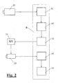
- FIG. 1 The interaction of the individual components of the measuring device and the basic principle of the measuring method according to the invention are shown schematically in FIG.
- the original V is pixel-wise photoelectrically scanned by the digital camera 20 and a digital color representation 41 of the original V is formed from the samples obtained and stored in the computer R-controlled by the computer R.
- the bridge 13 and the spectral measuring head 30 are in a rest position in which they are outside the detection range of the digital camera.
- the computer R determines, according to methods of image processing known per se, by means of suitable analysis software 42 and previously stored reference data from templates, the entirety of all measuring positions 43 at which the original is to be measured colorimetrically by means of the spectral measuring head 30. Further details will be explained below.
- the computer R then controls on the basis of these thus determined measuring positions 43 in a conventional manner to the total of 14 designated drive means for the displacement of the bridge 13 and the spectral measuring head 30 and thus moves the spectral measuring head 30 successively to all measuring positions. In every measuring position a measurement is triggered.
- the thereby obtained, generally designated 44 spectral measurement data are read into the computer R and stored there for further processing by a suitable processing program 45, such as one for creating device profiles.
- high-resolution is understood to mean that the size of the scanning points of the imaging unit, in this exemplary embodiment of the digital camera 20, is substantially smaller, in particular by a factor of> 10, than the measuring aperture of the color measuring head 30.
- FIGS. 3-5 schematically show an embodiment of the measuring device according to the invention constructed on the principle of a feed-in scanner.
- the illustrated measuring device comprises a housing 100 and on two opposite sides thereof a collection tray 101 and a discharge tray 102 which lie substantially in one plane.
- a document transport mechanism comprising two motor-driven roller pairs 103 and 104, guides 105 and 106 and two light barriers 107 and 108.
- the document transport mechanism is controlled by a conventional internal controller, not shown here, in combination with an external computer and allows a document V inserted into the input tray 101 in the direction of the arrow X along a substantially planar path defined by the guides 105 and 106 to be transported through the housing in the discharge tray 102 and vice versa.
- the imaging unit or line camera 120 can be constructed, for example, in a manner known per se as a color-capable CIS (contact image sensor). It typically comprises an opto-electrical line sensor 121, an optical imaging unit 122 and an illumination 123 for incident light measurement of opaque templates.
- the imaging unit 120 scans the document transversely to the transporting direction X thereof (in the direction of the arrow Y, FIG. 5) pointwise, wherein the second scanning dimension is detected by the advance of the document.
- the imaging unit is connected in a conventional manner with the internal control and the external computer, which reads in the scanning signals generated by it and forms a digital color representation of the template and stores it.
- the measuring device substantially corresponds to a conventional color-proof feed scanner for opaque templates, so that the expert in this regard requires no further explanation.
- a color or spectral measuring head 130 known per se is additionally provided in the housing 100 and by means of a displacement unit transverse to the transport direction X of the original V in the direction of the arrow Y (FIG Width of the template moved back and forth.
- the conventionally constructed displacement unit consists of a guide shaft 141, a support 142 and a motor-driven drive belt 143 (FIG. 5) and is controlled by the external computer in a manner also known per se.
- the shift unit allows the color or spectral measuring head 130 to be adjusted across the entire width of the document.
- the color or spectral measuring head 130 can be embodied with all technologies commonly used in colorimetry. It typically consists of a lighting unit; which is preferably designed as a 45 ° ring lighting, and a pick-up channel which supplies the light to be measured at 0 ° to a module which performs the spectral selection.
- the wavelength selection is preferably carried out with a diode array spectrometer or with a set of interference filters. Another method for wavelength selection is based on the use of LEDs with different ones Wavelengths as illumination and a spectrally broadband photoelectric receiver. Such a spectrometer is eg in the US Pat. No. 6,043,893 described.
- an additional illumination arrangement 150 is provided below the measuring aperture 131 of the color measuring head 130.
- the illumination arrangement 150 can at the same time also be embodied as transmission illumination for the imaging unit or line scan camera 120 and for this purpose comprises a deflection optics 153 and a further diffuser 154 which extends below the imaging unit along the same.
- a deflection optics 153 and a further diffuser 154 which extends below the imaging unit along the same.
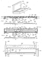
- FIGS. 6-9 schematically show an embodiment of the measuring device according to the invention constructed on the principle of a flatbed scanner. It consists on the one hand of a structure, as is customary in flatbed scanners, and on the other hand of a sliding over the entire template area color measuring head.
- the difference to a feeder scanner consists essentially only in that the template is stationary and for the scanning line is arranged to be movable relative to the original.
- the assembly 200 consists of a base 201 and a hinged lid 202 with a white insert 204, which serves as a background for remission measurements.
- the lower part 201 comprises a housing, which is closed at the top of a glass plate 203, on which the template to be measured V is placed.
- the line sensor extends in the Y direction and is arranged so that it can detect the entire width of the original.
- a spectrally operating color measuring head 230 with a measuring opening 231 is arranged displaceably on a displacement unit parallel to the scanning line 220, that is to say in the direction of the arrow Y.
- the displacement unit is essentially conventional and consists of a guide shaft 241, a support 242 and a motor-driven drive belt 243 (FIG. 8).
- the shift unit allows the color or spectral measuring head 230 to be adjusted across the entire width of the document.
- the imaging unit 220 and the colorimeter head 230 are in turn mounted on a second displacement unit which consists of a carriage 260, a guide shaft 261, a support 262, a roller 264 and a power driven drive belt 263 ( Figure 7).
- This second shifting unit allows the scanning line 220 to be displaced together with the color measuring head 230 in the direction of the arrow X, so that they can scan the entire original V.
- the shifting units, the scanning line and the color measuring head are, as in the preceding embodiment, in turn driven in a manner known per se by a conventional internal control, not shown here, in combination with an external computer.
- an additional illumination arrangement 250 is provided, which preferably - analogous to the exemplary embodiment of FIGS. 3-5 - simultaneously serves for the scanning line 220 and for the color measuring head 230.
- a transparent plate 205 is provided instead of the white insert 204.
- the illumination arrangement 250 comprises a light source 251 (eg a fluorescent tube) extending transversely across the template, a diffuser 252, a deflection optics 253 and a further diffuser 254, and black backgrounds 255 and 256.
- the illumination arrangement 250 is arranged on a further displacement unit which in the FIG is essentially the same as that for the common displacement of scanning line 220 and color measuring head 230 in the X direction and a guide shaft 271 and a motor-driven drive belt 273 consists.
- the additional illumination arrangement 250 is moved in parallel and synchronous with the scanning line 220 or with the color measuring head 230 in the direction of the arrow X during the scanning or colorimetric measurement.
- remission measurements with white or with a black background can be carried out.
- the measuring device essentially corresponds in structure and mode of operation to a conventional color-suitable flatbed scanner for opaque or transparent originals, so that the person skilled in the art needs no further explanation.
- the control of the individual components of this embodiment is analogous to the feed-scanner embodiment by the conventional internal control in combination with an external computer and therefore also requires no particular explanation.
- the measuring method according to the invention is described in more detail below with reference to the example of the measurement of an opaque color test chart (test chart) (remission measurement).
- the test chart to be measured is positioned on the measuring device according to the invention according to one of the described embodiments.
- a color image of the test chart is first recorded in a conventional manner and stored in the computer.
- This color image is taken with the calculator analyzed using image processing methods, whereby the type of test chart and the exact position of the individual color fields (measurement positions) are determined. Algorithms that can accomplish this task are well known today and described in the pertinent literature.
- a possible procedure for the analysis of the test chart is as follows: First the segmentation of the fields of the same color and the determination of their center of gravity are used to calculate a first approximation of the coordinates of the color fields. When segmenting the fields, the fact can be exploited that the color fields of a test card usually have the same size.
- the information thus obtained about the structure of the color test card (position and color of the color patches) is compared with the reference data of the color test cards (stored in the computer) and thus the type of color test chart is determined.
- the desired position of the color fields from the structure of the reference card is known, the previously calculated position of each color field can be checked and any artifacts in the image resulting Segment réellesirri and thus positioning errors can be eliminated.
- the colorimetric values and possibly the spectrum are determined with the color measuring head 30 or 130 or 230 at the measuring positions determined in this way and preferably stored in the computer in a format defined in a text file. From these colorimetric data of the original, it is then possible to use, for example, software known per se. an ICC profile can be calculated.
- the procedure for measuring a transmission test chart is analogous to the remission measurement described above.
- the inhomogeneity of the transmitted light illumination is measured with the scanner or the digital camera and the spectral measured values determined by the color measuring head are thereby compensated.
- the light distribution of the transmitted light illumination is measured and stored with the imaging unit. Thereafter, the test chart is placed in the scanner or on the measuring table and a picture taken of the same. This image is analyzed with a computer using image processing methods, determining the type of test chart and the exact location of each color field (see above). The colorimetric values and / or the spectrum of the color fields are subsequently determined with the color measuring head at the locations thus found.
- the artifacts in the spectral measurements which are caused by the locally non-constant (inhomogeneous) transmission illumination, can then be compensated with the previously recorded data of the image of the light distribution of the transmission illumination.
- an ICC profile of a foil printer can then be calculated from the colorimetric data determined in this way.
- Another important aspect of the invention is the possibility of measuring in the image to calculate rule recommendations for controlling output devices such as printing machines.
- spectral scanners are used today, which capture the complete spectrum of each pixel. While this is an elegant, but very expensive method due to the complex hardware of a spectral scanner.
- a suitable for this purpose spectral scanner the company Heidelberg printing machines is eg in EP-A 0 847 187 described.
- the prepress data of the original to be printed are transferred in digital form (eg in PDF or CIP3 format).
- digital form eg in PDF or CIP3 format.
- those points in the image are automatically determined in a manner known per se, which are best suited for the control because of their color composition (layer structure) and the homogeneity of the image hierarchy.
- the user can be given the opportunity to modify these points (add, delete or move points).
- a first sheet is now output and placed on the measuring device according to the invention.
- an image of the printed sheet is taken with a scanner or digital camera. This image is correlated with the prepress data, allowing the positions of the spectrally measured points on the template to be determined very accurately without user interaction.
- the colorimetric information is now determined with the spectral measuring head, and from this, using suitable algorithms, the rule recommendations for the output device are determined in a manner known per se. With the settings of the output device that are new according to these rule recommendations, another sheet is output and measured as described above, and the control parameters are adjusted, if necessary, until the required quality is achieved. Thereafter, only at certain intervals an arc is measured and, if appropriate, the control parameters adjusted to guarantee a consistent quality of the output.
- the user does not have to specify the position of the color patches (measurement positions) as well as the type of the test chart, since this information is determined by means of image processing methods from the image data of the template. This procedure increases user-friendliness and eliminates a potential source of error.
- the high local resolution of the scanner or the digital camera which can be achieved in comparison to a scanning color measuring head, makes the position of the color fields very accurate be determined.
- the smallest colorimetrically measurable color field size can only be selected to be insignificantly larger than the measuring aperture of the color measuring head, without erroneous measurements resulting from incorrect positioning and thus co-evaluation of the light from adjacent fields.
- Small boxes allow a large number of color patches for a given document size, which benefits the quality of the ICC profiles.
- the time required to acquire the colorimetric measured values is significantly shortened.
- test chart is not only colormetrically but also digitally as a high-resolution image after the measurement, artefacts resulting from contamination or scratches can be detected in the colorimetric measured values and ignored, corrected or measured again.
- the color measurement head can be used to significantly increase the accuracy of the colorimetric values by multiple measurements at various points in the field and subsequent averaging. From the analysis of the image data of the template, the homogeneity of the individual color fields can be determined. If this is low, the quality can be kept within acceptable limits automatically by multiple measurements.
- the measurement time can be significantly shortened.
Abstract
Description
Die Erfindung betrifft ein Verfahren und eine Vorrichtung zur farbmetrischen Ausmessung einer zweidimensionalen Vorlage gemäß dem Oberbegriff des unabhängigen Anspruchs 1 bzw. des unabhängigen Anspruchs 10.The invention relates to a method and a device for the colorimetric measurement of a two-dimensional original according to the preamble of independent claim 1 and independent claim 10, respectively.
Im Zuge der immer weiteren Verbreitung von farbtauglicher Computerperipherie und den allgemein steigenden Qualitätsansprüchen an die Farbechtheit von Druckerzeugnissen gewinnt auch das sog. Color Management, d.h. die gegenseitige Abstimmung aller farbtauglichen Computer-Peripherie-Geräte (Monitor, Scanner, Drucker etc.) sowie die farbmetrische Regelung von Ausgabegeräten eine immer stärkere Bedeutung.In the course of the ever-increasing use of color-capable computer peripherals and the generally increasing quality demands on the color fastness of printed products, so-called color management, i. the mutual coordination of all color-suitable computer peripheral devices (monitor, scanner, printer, etc.) and the colorimetric control of output devices is becoming increasingly important.
Ein zentraler Punkt des Color Management ist die Erstellung von herstellerspezifischen oder einer Norm (z.B. ICC) entsprechenden Geräteprofilen. Diese Geräteprofile ermöglichen die Umrechnung von gerätespezifischen Farbwerten in geräteunabhängige und somit allgemeingültige und somit kommunizierbare Farbwerte. Die Erstellung von Geräteprofilen basiert auf der Charakterisierung der farbmetrischen Eigenschaften der Ein- und Ausgabegeräte wie Farbdrucker und Scanner. Diese erfordert die farbmetrische Bewertung von Farbtestkarten (so genannten Testcharts), wie sie z.B. in der ISO Norm IT8 beschrieben sind. Eine solche Testchart setzt sich üblicherweise aus mehreren Hundert Testfeldern zusammen.A central point of color management is the creation of device-specific or standard (e.g., ICC) device profiles. These device profiles enable the conversion of device-specific color values into device-independent and thus generally valid and therefore communicable color values. The creation of device profiles is based on the characterization of the colorimetric properties of input and output devices such as color printers and scanners. This requires the colorimetric evaluation of color test cards (so-called test charts), as described e.g. described in the ISO standard IT8. Such a test chart usually consists of several hundred test fields.
Für das Einmessen der Farbfelder einer Testchart existieren heute eine. Reihe von Methoden.For measuring the color fields of a test chart, there is one today. Set of methods.
So werden die Farbfelder z.B. mit einem Hand-Farbmessgerät, das heißt einem Colorimeter oder Spektrometer wie z.B. in
Oder die Farbfelder werden mit einem scannenden Hand-Messgerät, wie z.B. in
Nach
In
Ein weiteres bekanntes Verfahren besteht darin, ein auf einem XY-Verschiebetisch montiertes Messgerät einzusetzen, welches die Testchart computergesteuert ausmisst. Ein typischer Vertreter einer solchen Anordnung ist die Kombination der unter den Bezeichnungen Spectrolino und SpectroScan vertriebenen Geräte der Anmelderin. Am Anfang des Einmessvorganges muss der Benutzer dem Gerät die Position der Eckpunkte der Messfeldanordnung angegeben, was eine potentielle Fehlerquelle darstellt.Another known method is to use a measuring device mounted on an XY translation stage, which measures the test chart computer-controlled. A typical representative of such an arrangement is the combination of Applicant's devices sold under the names Spectrolino and SpectroScan. At the beginning of the calibration process, the user must indicate to the instrument the position of the corner points of the patch array, which is a potential source of error.
Nach
Durch die vorliegende Erfindung sollen nun ein Verfahren und eine Vorrichtung der gattungsgemäßen Art dahingehend verbessert und die konstruktiven und konzeptionellen Voraussetzungen geschaffen werden, dass mit vertretbarem konstruktiven Aufwand der komplette Ablauf des Einmessens einer Remissions- oder Transmissions-Vorlage ohne Interaktion des Anwenders in kurzer Zeit ausgeführt werden kann, wobei der Arbeitsaufwand des Anwenders auf ein Minimum reduziert wird und gleichzeitig Fehlmanipulationen ausgeschlossen werden.By means of the present invention, a method and a device of the generic type are to be improved and the constructional and conceptual prerequisites are created so that the complete procedure of measuring a remission or transmission template without any user interaction takes place within a short time with reasonable design effort while reducing the user's workload to a minimum while eliminating false manipulation.
Die Lösung dieser der Erfindung zugrunde liegenden Aufgabe ergibt sich aus den im kennzeichnenden Teil des unabhängigen Anspruchs 1 bzw. des unabhängigen Anspruchs 10 beschriebenen Merkmalen. Besonders vorteilhafte Ausgestaltungen und Weiterbildungen sind Gegenstand der abhängigen Ansprüche.The solution of this problem underlying the invention results from the features described in the characterizing part of the independent claim 1 and the independent claim 10. Particularly advantageous embodiments and further developments are the subject of the dependent claims.
gemäß dem grundlegendsten Gedanken der Erfindung wird also zum einen die Bildinformation der Vorlage hochauflösend elektronisch erfasst und mit Methoden der Bildverarbeitung analysiert und zum ändern wird die aus der Analyse gewonnene Information über die Vorlage zur Steuerung der Positionierung des Farbmesskopfes eingesetzt. Der Farbmesskopf dient dabei der Erfassung von farbmetrisch Werten an den sich aus der jeweiligen Anwendung ergebenden Messpositionen auf der Vorlage.Thus, according to the most basic idea of the invention, on the one hand, the image information of the original is recorded in high-resolution electronically and analyzed with methods of image processing and, to change, the information obtained from the analysis of the Template used to control the positioning of the colorimeter. The color measuring head serves to acquire colorimetric values at the measuring positions resulting from the respective application on the original.
Der Anwendungsbereich der Erfindung liegt beispielsweise bei der Erfassung der farbmetrischen Werte der zahlreichen Farbfelder einer Testchart, welche für die Erstellung von ICC Profilen genutzt werden kann, oder dem Regeln von farbfähigen Ausgabegeräten direkt aus der Messung von farbmetrischen Werten in der Vorlage, welche typischerweise aus einem Bild besteht. Der komplette Ablauf des Einmessens einer Remissions- oder Transmissions-Testchart kann ohne Interaktion des Anwenders in kurzer Zeit ausgeführt werden. Der Arbeitsaufwand des Anwenders wird so auf ein Minimum reduziert, und Fehlmanipulationen können ausgeschlossen werden.The scope of the invention is, for example, in the detection of the colorimetric values of the numerous color patches of a test chart, which can be used for the creation of ICC profiles, or the regulation of color-capable output devices directly from the measurement of colorimetric values in the template, which typically consists of a Picture exists. The complete process of measuring a remission or transmission test chart can be performed in a short time without user interaction. The workload of the user is reduced to a minimum, and mishandling can be excluded.
Je nach Ausführungsform der Erfindung kann diese auch als selbst kalibrierende und selbst profilierende und somit farbverbindliche Digital-Kamera respektive Scanner eingesetzt werden.Depending on the embodiment of the invention, this can also be used as self-calibrating and self-profiling and thus color-binding digital camera respectively scanner.
Im folgenden wird die Erfindung anhand der Zeichnung näher erläutert. Es zeigen:
- Fig. 1
- eine Gesamtansicht eines ersten Ausführungsbeispiels der erfindungsgemäßen Messvorrichtung,
- Fig. 2
- ein Schema zur Erläuterung des erfindungsgemäßen Verfahrens,
- Fig. 3
- eine Gesamtansicht eines zweiten Ausführungsbeispiels der erfindungsgemäßen Messvorrichtung,
- Fig. 4
- einen schematischen Längsschnitt durch die Messvorrichtung der Fig. 3,
- Fig. 5
- eine Draufsicht auf die Messvorrichtung der Fig. 3 bei abgenommenem Gehäusedeckel,
- Fig. 6
- eine Gesamtansicht eines dritten Ausführungsbeispiels der erfindungsgemäßen Messvorrichtung,
- Fig. 7
- einen schematischen Längsschnitt durch die Messvorrichtung der Fig. 6 mit geschlossenem Deckel,
- Fig. 8
- eine schematische, um 90 DEG gedrehte Aufsicht nach der Linie VIII-VIII der Fig. 7 und
- Fig. 9
- einen schematischen Längsschnitt durch eine Variante der Messvorrichtung der Fig. 6 mit geschlossenem Deckel.
- Fig. 1
- an overall view of a first embodiment of the measuring device according to the invention,
- Fig. 2
- a scheme for explaining the method according to the invention,
- Fig. 3
- an overall view of a second embodiment of the measuring device according to the invention,
- Fig. 4
- a schematic longitudinal section through the measuring device of Fig. 3,
- Fig. 5
- 3 shows a top view of the measuring device of FIG. 3 with the housing cover removed;
- Fig. 6
- an overall view of a third embodiment of the measuring device according to the invention,
- Fig. 7
- a schematic longitudinal section through the measuring device of FIG. 6 with a closed lid,
- Fig. 8
- a schematic, rotated by 90 ° view on the line VIII-VIII of Fig. 7 and
- Fig. 9
- a schematic longitudinal section through a variant of the measuring device of FIG. 6 with a closed lid.
Die in Fig. 1 dargestellte erste Ausführungsform der erfindungsgemäßen Messvorrichtung umfasst einen als Ganzes mit 10 bezeichneten XY-Verschiebetisch und eine hochauflösende farbtaugliche bildgebende Einheit bzw. fotoelektrische Abtasteinrichtung in Form einer Digitalkamera 20, welche mittels eines Stativs 21 über dem Verschiebetisch 10 montiert ist. Ferner ist am Stativ 20 eine Beleuchtungseinrichtung 22 befestigt.The illustrated in Fig. 1 the first embodiment of the measuring device according to the invention comprises an XY translation table designated as a whole by 10 and a high-resolution color capable imaging unit or photoelectric scanning device in the form of a
Der Verschiebetisch 10 umfasst einen im wesentlichen rechteckigen Unterbau 11 mit einer Auflageplatte 12 für eine auszumessende Vorlage V (z.B. eine Farbtestkarte) sowie eine Brücke 13, an der ein Spektralmesskopf 30 montiert ist. Die Brücke 13 ist mittels nicht dargestellter motorischer Antriebsmittel in Richtung des Doppelpfeils X parallel zur Längsseite des Unterbaus verschiebbar. Der Spektralmesskopf 30 ist mittels nicht dargestellter motorischer Antriebsmittel in Richtung des Doppelpfeils Y parallel zur Breitseite des Unterbaus verschiebbar an der Brücke 13 gelagert. Durch Verschiebung der Brücke in X-Richtung und Verschiebung des Spektralmesskopfs an der Brücke in Y-Richtung kann der Spektralmesskopf 30 an jede beliebige Messposition auf der auf der Auflageplatte 12 befindlichen Vorlage V gefahren werden, wobei die Steuerung der Bewegung des Spektralmesskopfs durch einen Rechner R (Fig. 2) erfolgt, der die Angaben über die anzufahrenden Messpositionen enthält. Der Rechner R steuert auch die Auslösung der Messvorgänge des Spektralmesskopfs 30 und den Transfer der dabei ermittelten Messwerte (hier Spektralmesswerte) in einen Speicher des Rechners.The translation stage 10 includes a substantially
Der Spektralmesskopf 30 ist in an sich bekannter Weise als kombinierter Remissions/Transmissionsmesskopf ausgebildet. Für Transmissionsmessungen ist die Auflageplatte 12 transparent ausgebildet, und im Unterbau ist eine hier nicht dargestellte Beleuchtungsanordnung vorgesehen, welche die nutzbare, vom Spektralmesskopf 30 überstreichbare Fläche der Auflageplatte 12 möglichst homogen ausleuchtet. Der rechnergesteuerte Verschiebetisch 10 und der Spektralmesskopf 30 entsprechen soweit voll und ganz dem Stand der Technik, so dass der Fachmann keiner weiteren Erläuterung bedarf. Ein Beispiel für einen bekannten Spektralmesskopf und einen bekannten Verschiebetisch seien die unter den Bezeichnungen "Spectrolino" bzw. "SpectroScan" von der Anmelderin vertriebenen Geräte angeführt. Ein für die vorliegende Erfindung geeigneter bekannter Spektralmesskopf ist beispielsweise auch in der
Die ebenfalls konventionelle und an den Rechner R angeschlossene, farbtaugliche Digitalkamera 20 erfasst die auf der Auflageplatte 12 liegende Vorlage V und erzeugt eine hochaufgelöste digitale Farbdarstellung der gesamten oder zumindest des relevanten Bereichs der Vorlage. Bei opaken Vorlagen dient die Beleuchtungseinrichtung 22 zur Ausleuchtung der Vorlage während der Abtastung durch die Digitalkamera. Im Falle von transparenten Vorlagen wird dazu die im Unterbau befindliche Beleuchtungsanordnung eingesetzt.The likewise conventional and color-compatible
Das Zusammenwirken der einzelnen Komponenten der Messvorrichtung sowie das grundlegende Prinzip des erfindungsgemäßen Messverfahrens sind schematisch in Fig. 2 dargestellt.The interaction of the individual components of the measuring device and the basic principle of the measuring method according to the invention are shown schematically in FIG.
Zunächst wird - gesteuert durch den Rechner R - mittels der Digitalkamera 20 die Vorlage V pixelweise fotoelektrisch abgetastet und aus den dabei gewonnenen Abtastwerten eine digitale Farbdarstellung 41 der Vorlage V gebildet und im Rechner R abgespeichert. Die Brücke 13 und der Spektralmesskopf 30 befinden sich dabei in einer Ruheposition, in der sie außerhalb des Erfassungsbereichs der Digitalkamera liegen. Aus dieser Farbdarstellung 41 ermittelt dann der Rechner R nach an sich bekannten Methoden der Bildverarbeitung mittels einer passenden Analyse-Software 42 und anhand vorgängig gespeicherter Referenzdaten von Vorlagen die Gesamtheit aller Messpositionen 43, an denen die Vorlage mittels des Spektralmesskopfs 30 farbmetrisch ausgemessen werden soll. Näheres dazu wird weiter unten noch ausgeführt. Der Rechner R steuert dann aufgrund dieser so ermittelten Messpositionen 43 in an sich bekannter Weise die insgesamt mit 14 bezeichneten Antriebsmittel für die Verschiebung der Brücke 13 und des Spektralmesskopfs 30 an und verfährt damit den Spektralmesskopf 30 sukzessive an alle Messpositionen. In jeder Messposition wird eine Messung ausgelöst. Die dabei gewonnenen, gesamthaft mit 44 bezeichneten spektralen Messdaten werden in den Rechner R eingelesen und dort für die weitere Verarbeitung durch ein geeignetes Verarbeitungsprogramm 45, z.B. ein solches zur Erstellung von Geräteprofilen, gespeichert.First, the original V is pixel-wise photoelectrically scanned by the
Die beschriebenen Vorgänge gelten grundsätzlich in gleicher Weise für die Ausmessung von opaken wie auch von transparenten Vorlagen, der Unterschied liegt im wesentlichen lediglich in der Ausleuchtung der Vorlage während der bilderzeugenden Abtastung mittels der Digitalkamera und der spektralen Ausmessung mittels des Spektralmesskopfs.The described processes apply in principle in the same way for the measurement of opaque as well as of transparent originals, the difference lies essentially only in the illumination of the original during the image-forming scanning by means of the digital camera and the spectral measurement by means of the spectral measuring head.
Unter hochauflösend wird im Zusammenhang mit der vorliegenden Erfindung verstanden, dass die Größe der Abtastpunkte der bildgebenden Einheit, in diesem Ausführungsbeispiel also der Digitalkamera 20, wesentlich geringer, insbesondere um einen Faktor >10 geringer ist als die Messapertur des Farbmesskopfs 30.In the context of the present invention, high-resolution is understood to mean that the size of the scanning points of the imaging unit, in this exemplary embodiment of the
In den Figuren 3-5 ist schematisch eine nach dem Prinzip eines Einzug-Scanners aufgebaute Ausführungsform der erfindungsgemäßen Messvorrichtung dargestellt. Die dargestellte Messvorrichtung umfasst ein Gehäuse 100 und an zwei gegenüberliegenden Seiten desselben eine Einzugslade 101 und eine Ausgabelade 102, welche im wesentlichen in einer Ebene liegen. Im Inneren des Gehäuses 100 befindet sich ein Vorlagentransportmechanismus, der zwei motorisch angetriebene Walzenpaare 103 und 104, Führungen 105 und 106 und zwei Lichtschranken 107 und 108 umfasst. Der Vorlagentransportmechanismus wird von einer hier nicht dargestellten, konventionellen internen Steuerung in Kombination mit einem externen Rechner gesteuert und gestattet es, eine in die Einzugslade 101 eingeführte Vorlage V in Richtung des Pfeils X längs eines durch die Führungen 105 und 106 definierten, im wesentlichen ebenen Pfades durch das Gehäuse in die Ausgabelade 102 zu transportieren und umgekehrt.FIGS. 3-5 schematically show an embodiment of the measuring device according to the invention constructed on the principle of a feed-in scanner. The illustrated measuring device comprises a
Im Gehäuse 100 befindet sich ferner im Bewegungspfad der Vorlage V feststehend eine farbtaugliche bildgebende Einheit bzw. fotoelektrische Abtasteinrichtung in Form einer Abtastzeile (Zeilenkamera) 120, welche sich über die gesamte Breite (quer zur Vorschubrichtung X) der Vorlage V erstreckt, so dass sie die gesamte Breite der Vorlage erfassen kann. Die bildgebende Einheit bzw. Zeilenkamera 120 kann z.B. in an sich bekannter Weise als farbtauglicher CIS (Contact Image Sensor) aufgebaut sein. Sie umfasst typischerweise einen optoelektrischen Zeilensensor 121, eine optische Abbildungseinheit 122 und eine Beleuchtung 123 für die Auflichtmessung von opaken Vorlagen. Die bildgebende Einheit 120 tastet die Vorlage quer zur Transportrichtung X derselben (in Richtung des Pfeils Y, Fig. 5) punktweise ab, wobei die zweite Abtastdimension durch den Vorschub der Vorlage erfasst wird. Die bildgebende Einheit ist in an sich bekannter Weise mit der internen Steuerung und dem externen Rechner verbunden, der die von ihr erzeugten Abtastsignale einliest und daraus eine digitale Farbdarstellung der Vorlage bildet und abspeichert.In the
Soweit entspricht die Messvorrichtung im wesentlichen einem herkömmlichen farbtauglichen Einzug-Scanner für opake Vorlagen, so dass der Fachmann diesbezüglich keiner näheren Erläuterung bedarf.As far as the measuring device substantially corresponds to a conventional color-proof feed scanner for opaque templates, so that the expert in this regard requires no further explanation.
Gemäß einem wichtigen Aspekt der Erfindung ist im Gehäuse 100 neben der bildgebenden Einheit 120 zusätzlich ein an sich bekannter Farb- oder Spektralmesskopf 130 vorgesehen und mittels einer Verschiebeeinheit quer zur Transportrichtung X der Vorlage V in Richtung des Pfeils Y (Fig. 5) über die gesamte Breite der Vorlage hin und her bewegbar. Die konventionell aufgebaute Verschiebeeinheit besteht aus einer Führungswelle 141, einer Auflage 142 und einem motorisch angetrieben Antriebsriemen 143 (Fig. 5) und wird vom externen Rechner in ebenfalls an sich bekannter Weise angesteuert. Die Verschiebeeinheit erlaubt es, den Farb- bzw. Spektralmesskopf 130 quer über die gesamte Vorlagenbreite zu verstellen.According to an important aspect of the invention, in addition to the
Der Farb- bzw. Spektralmesskopf 130 kann mit allen üblicherweise in der Farbmetrik eingesetzten Technologien ausgeführt sein. Er besteht typischerweise aus einer Beleuchtungseinheit; welche vorzugsweise als 45° -Ringbeleuchtung ausgeführt ist, und einem Aufpickkanal, der unter 0° das zu messende Licht einem Modul, welches die spektrale Selektion vornimmt, zuführt. Die Wellenlängenselektion ist vorzugsweise mit einem Diodenzeilen-Spektrometer oder mit einem Satz von Interferenzfiltern ausgeführt. Eine weitere Methode zur Wellenlängenselektion basiert auf dem Einsatz von LED mit verschiedenen Wellenlängen als Beleuchtung und einem spektral breitbandigen fotoelektrischen Empfänger. Ein solches Spektrometer ist z.B. in der
Durch Querverstellung des Farbmesskopfs 130 in Y-Richtung mittels der Verschiebeeinheit und durch Längsbewegung der Vorlage in X-Richtung mittels des Vorlagentransportmechanismus kann der Farbmesskopf 130 an jeder beliebigen Messposition auf der Vorlage V positioniert werden und die Vorlage mittels des Messkopfs an diesen Messpositionen farbmetrisch (bzw. spektral) ausgemessen werden. Die Steuerung der Positionierung des Farbmesskopfs 130 erfolgt wie beim ersten Ausführungsbeispiel wiederum durch den Rechner aufgrund der von diesem aus der digitalen Farbdarstellung der Vorlage ermittelten Messpositionen.By transverse adjustment of the
Um auch Messungen an transparenten Vorlagen durchführen zu können, ist unterhalb der Messblende 131 des Farbmesskopfs 130 eine zusätzliche Beleuchtungsanordnung 150 vorgesehen. Diese umfasst eine sich quer über die Vorlage erstreckende Leuchtquelle 151 (z.B. eine Leuchtstoffröhre oder eine linienförmige Anordnung von Leuchtdioden) und einen Diffusor 152, der sich längs der Bewegungsbahn des Farbmesskopfs 130 unmittelbar gegenüber dessen Messblende erstreckt. Die Beleuchtungsanordnung 150 kann gleichzeitig auch als Transmissionsbeleuchtung für die bildgebende Einheit bzw. Zeilenkamera 120 ausgebildet sein und umfasst zu diesem Zweck eine Umlenkoptik 153 und einen weiteren Diffusor 154, der sich unter der bildgebenden Einheit längs derselben erstreckt. Selbstverständlich können z.B. aus Platzgründen für den Farbmesskopf 130 und die bildgebende Einheit 120 auch separate Transmissionsbeleuchtungen vorgesehen sein.In order to be able to carry out measurements on transparent documents, an
In den Figuren 6-9 ist schematisch eine nach dem Prinzip eines Flachbett-Scanners aufgebaute Ausführungsform der erfindungsgemäßen Messvorrichtung dargestellt. Sie besteht einerseits aus einem Aufbau, wie er bei Flachbettscannern üblich ist, und andererseits aus einem über den ganzen Vorlagenbereich verschiebbaren Farbmesskopf. Der Unterschied zu einem Einzug-Scanner besteht im wesentlichen nur darin, dass die Vorlage ortsfest und dafür die Abtastzeile relativ zur Vorlage beweglich angeordnet ist.FIGS. 6-9 schematically show an embodiment of the measuring device according to the invention constructed on the principle of a flatbed scanner. It consists on the one hand of a structure, as is customary in flatbed scanners, and on the other hand of a sliding over the entire template area color measuring head. The difference to a feeder scanner consists essentially only in that the template is stationary and for the scanning line is arranged to be movable relative to the original.
Der Aufbau 200 besteht aus einem Unterteil 201 und einem aufklappbaren Deckel 202 mit einer weißen Einlage 204, die als Hintergrund für Remissionsmessungen dient. Der Unterteil 201 umfasst ein Gehäuse, welches oben von einer Glassplatte 203 abgeschlossen ist, auf welche die zu messende Vorlage V gelegt wird. Unter der Glassplatte (Fig. 7) befindet sich eine bildgebende Einheit in Form einer Abtastzeile (Zeilenkamera) 220, welche vorzugsweise als CIS (Contact Image Sensor) ausgeführt ist und ihrerseits aus einem optoelektrischen Zeilensensor 221, einer optischen Abbildungseinheit 222 und einer Beleuchtungseinheit 223 für die Auflichtsmessung von opaken Vorlagen besteht. Der Zeilensensor erstreckt sich in Y-Richtung und ist so angeordnet, dass er die gesamte Breite der Vorlage erfassen kann.The
Neben der Abtastzeile 220 ist ein spektral arbeitender Farbmesskopf 230 mit einer Messöffnung 231 auf einer Verschiebeeinheit parallel zur Abtastzeile 220, also in Richtung des Pfeils Y verschiebbar angeordnet. Die Verschiebeeinheit ist im wesentlichen konventionell ausgebildet und besteht aus einer Führungswelle 241, einer Auflage 242 und einem motorisch angetrieben Antriebsriemen 243 (Fig. 8). Die Verschiebeeinheit erlaubt es, den Farb- bzw. Spektralmesskopf 230 quer über die gesamte Vorlagenbreite zu verstellen.In addition to the
Die bildgebende Einheit bzw. Abtastzeile 220 und der Farbmesskopf 230 sind ihrerseits auf einer zweiten Verschiebeeinheit montiert, welche aus einem Schlitten 260, einer Führungswelle 261, einer Auflage 262, einer Rolle 264 und einem motorisch angetrieben Antriebsriemen 263 (Fig. 7) besteht. Diese zweite Verschiebeeinheit erlaubt es, die Abtastzeile 220 zusammen mit dem Farbmesskopf 230 in Richtung des Pfeils X zu verschieben, so dass sie die ganze Vorlage V abtasten können.The
Die Verschiebeeinheiten, die Abtastzeile und der Farbmesskopf werden wie beim vorgehenden Ausführungsbeispiels wiederum von einer hier nicht dargestellten, konventionellen internen Steuerung in Kombination mit einem externen Rechner in an sich bekannter Weise angesteuert.The shifting units, the scanning line and the color measuring head are, as in the preceding embodiment, in turn driven in a manner known per se by a conventional internal control, not shown here, in combination with an external computer.
Um auch Messungen an transparenten Vorlagen durchführen zu können, ist bei der in Fig. 9 skizzierten Ausführungsvariante der erfindungsgemäßen Messvorrichtung im Deckel 202 des Aufbaus eine zusätzliche Beleuchtungsanordnung 250 vorgesehen, welche vorzugsweise - analog dem Ausführungsbeispiel der Figuren 3-5 - gleichzeitig für die Abtastzeile 220 und für den Farbmesskopf 230 dient. Außerdem ist anstelle der weißen Einlage 204 eine transparente Platte 205 vorgesehen. Die Beleuchtungsanordnung 250 umfasst eine sich quer über die Vorlage erstreckende Leuchtquelle 251 (z.B. eine Leuchtstoffröhre), einen Diffusor 252, eine Umlenkoptik 253 und einen weiteren Diffusor 254 sowie schwarze Hintergründe 255 und 256. Die Beleuchtungsanordnung 250 ist auf einer weiteren Verschiebeinheit angeordnet, welche im wesentlichen gleich aufgebaut ist wie diejenige zur gemeinsamen Verschiebung von Abtastzeile 220 und Farbmesskopf 230 in X-Richtung und aus einer Führungswelle 271 und einem motorisch angetrieben Antriebsriemen 273 besteht. Die zusätzliche Beleuchtungsanordnung 250 wird während der Abtastung bzw. farbmetrischen Ausmessung parallel und synchron zur Abtastzeile 220 bzw. zum Farbmesskopf 230 in Richtung des Pfeils X bewegt. Je nach Relativstellung der zusätzlichen Beleuchtungseinheit 250 können Remissionsmessungen mit weißem oder mit schwarzem Hintergrund durchgeführt werden.In order to be able to carry out measurements on transparent documents, the embodiment of the measuring device according to the invention in the
Mit Ausnahme des Vorhandenseins des Farbmesskopfs 230 entspricht die Messvorrichtung in Aufbau und Funktionsweise im wesentlichen einem herkömmlichen farbtauglichen Flachbett-Scanner für opake bzw. transparente Vorlagen, so dass der Fachmann diesbezüglich keiner näheren Erläuterung bedarf. Die Ansteuerung der einzelnen Komponenten dieser Ausführungsform erfolgt analog der Einzug-Scanner-Ausführungsform durch die konventionelle interne Steuerung in Kombination mit einem externen Rechner und bedarf deshalb ebenfalls keiner besonderen Erläuterung.With the exception of the presence of the
Im folgenden wird das erfindungsgemäße Messverfahren anhand des Beispiels der Ausmessung einer opaken Farbtestkarte (Testchart) näher beschrieben (Remissionsmessung).The measuring method according to the invention is described in more detail below with reference to the example of the measurement of an opaque color test chart (test chart) (remission measurement).
Die zu messende Testchart wird auf der erfindungsgemäßen Messvorrichtung gemäß einer der beschriebenen Ausführungsformen positioniert. Mit der Digitalkamera 20 oder der Abtastzeile 120 bzw. 220 wird zuerst in an sich konventioneller Weise ein Farbbild der Testchart aufgenommen und im Rechner abgespeichert. Dieses Farbbild wird mit dem Rechner mit Methoden der Bildverarbeitung analysiert, wobei der Typ der Testchart sowie die genaue Lage der einzelnen Farbfelder (Messpositionen) bestimmt werden. Algorithmen, die diese Aufgabe ausführen können, sind heute hinlänglich bekannt und in der einschlägigen Literatur beschrieben.The test chart to be measured is positioned on the measuring device according to the invention according to one of the described embodiments. With the
Ein mögliches Vorgehen für die Analyse der Testchart ist wie folgt: Zuerst wird mit der Segmentierung der Felder gleicher Farbe sowie der Bestimmung deren Schwerpunkts eine erste Näherung der Koordinaten der Farbfelder berechnet. Bei der Segmentierung der Felder kann die Tatsache ausgenutzt werden, dass die Farbfelder einer Testkarte üblicherweise die gleiche Größehaben. Die so gewonnene Information über den Aufbau der Farbtestkarte (Lage und Farbe der Farbfelder) wird mit den (im Rechner gespeicherten) Referenzdaten der Farbtestkarten verglichen und so der Typ der Farbtestkarte bestimmt. jetzt die Sollage der Farbfelder aus dem Aufbau der Referenzkarte bekannt ist, kann die zuvor berechnete Lage jedes einzelnen Farbfelds überprüft und allfällige durch Artefakte im Bild entstandene Segmentierungsfehler und somit Positionierungsfehler eliminiert werden.A possible procedure for the analysis of the test chart is as follows: First the segmentation of the fields of the same color and the determination of their center of gravity are used to calculate a first approximation of the coordinates of the color fields. When segmenting the fields, the fact can be exploited that the color fields of a test card usually have the same size. The information thus obtained about the structure of the color test card (position and color of the color patches) is compared with the reference data of the color test cards (stored in the computer) and thus the type of color test chart is determined. now the desired position of the color fields from the structure of the reference card is known, the previously calculated position of each color field can be checked and any artifacts in the image resulting Segmentierungsfehler and thus positioning errors can be eliminated.
Anschließend werden mit dem Farbmesskopf 30 bzw. 130 bzw. 230 an den so ermittelten Messpositionen die farbmetrischen Werte und ev. das Spektrum bestimmt und vorzugsweise in einem Textfile definierten Formates im Rechner abgespeichert. Aus diesen farbmetrischen Daten der Vorlage kann dann mit einer an sich bekannten Software z.B. ein ICC Profil berechnet werden.Subsequently, the colorimetric values and possibly the spectrum are determined with the
Der Ablauf zum Ausmessen einer Transmissions-Testchart ist analog wie bei der vorstehend beschrieben Remissionsmessung. Zusätzlich wird mit dem Scanner oder der digitalen Kamera die Inhomogenität der Durchlichtbeleuchtung ausgemessen und die vom Farbmesskopf ermittelten Spektralmesswerte werden damit kompensiert.The procedure for measuring a transmission test chart is analogous to the remission measurement described above. In addition, the inhomogeneity of the transmitted light illumination is measured with the scanner or the digital camera and the spectral measured values determined by the color measuring head are thereby compensated.
Vor dem Einlegen der Transnüssionstestchart (Dia, Film, Folie ..) in den Scanner gemäß den Figuren 3-9 oder auf den Messtisch gemäß Fig. 1 wird mit der bildgebenden Einheit die Lichtverteilung der Durchlichtbeleuchtung ausgemessen und abgespeichert. Danach wird die Testchart in den Scanner oder auf den Messtisch gelegt und ein Bild derselben aufgenommen. Dieses Bild wird mit einem Rechner mit Methoden der Bildverarbeitung analysiert, wobei der Typ der Testchart sowie die genaue Lage der einzelnen Farbfelder bestimmt werden (siehe oben). Anschließend werden mit dem Farbmesskopf an den so gefundenen Orten die farbmetrischen Werte und oder das Spektrum der Farbfelder bestimmt. Die Artefakte in den Spektralmesswerten, welche durch die örtlich nicht konstante (inhomogene) Transmissionbeleuchtung verursacht werden, können Anschließend mit den zuvor aufgenommenen Daten des Bildes der Lichtverteilung der Transmissionbeleuchtung kompensiert werden. Aus den so ermittelten farbmetrischen Daten kann dann beispielsweise ein ICC Profil eines Foliendruckers berechnet werden.Before inserting the Transnüssionstestchart (slide, film, foil ..) in the scanner according to Figures 3-9 or on the measuring table of FIG. 1, the light distribution of the transmitted light illumination is measured and stored with the imaging unit. Thereafter, the test chart is placed in the scanner or on the measuring table and a picture taken of the same. This image is analyzed with a computer using image processing methods, determining the type of test chart and the exact location of each color field (see above). The colorimetric values and / or the spectrum of the color fields are subsequently determined with the color measuring head at the locations thus found. The artifacts in the spectral measurements, which are caused by the locally non-constant (inhomogeneous) transmission illumination, can then be compensated with the previously recorded data of the image of the light distribution of the transmission illumination. For example, an ICC profile of a foil printer can then be calculated from the colorimetric data determined in this way.
Ein weiterer wichtiger Aspekt der Erfindung ist die Möglichkeit der Messung im Bild zur Berechnung von Regelempfehlungen zur Regelung von Ausgabegeräten wie zum Beispiel Druckmaschinen. Zur Regelung von Druckmaschinen mittels "Messung im Bild", wie z.B. in
Die erfindungsgemäße Kombination einer Digital-Kamera oder eines Scanners mit einem in X- und Y-Richtung verschiebbaren Farb- oder Spektralmesskopf kann mit deutlich geringerem technischen Aufwand, als für einen kompletten Spektralscanner nötig ist, realisiert werden und bei nur leicht größerem Zeitbedarf vergleichbare Resultate liefern.The inventive combination of a digital camera or a scanner with a displaceable in the X and Y direction color or spectral measuring head can be realized with significantly less technical effort than is necessary for a complete spectral scanner and provide comparable results with only slightly greater time requirements ,
Im folgenden ist ein typischer Ablauf der Regelung eines Ausgabegerätes durch spektrale Messung im Bild beschrieben.The following is a typical sequence of control of an output device by spectral measurement is described in the picture.
Die Prepress Daten der zu druckenden Vorlage werden in digitaler Form (z.B. im PDF- oder CIP3-Format) übernommen. Mittels geeigneter Algorithmen werden in an sich bekannter Weise diejenigen Punkte im Bild automatisch bestimmt, welche sich aufgrund ihrer farblichen Zusammensetzung (Schichtaufbau) und der Homogenität der Bildregiori für die Regelung am besten eignen. Dem Anwender kann die Möglichkeit gegeben werden diese Punkte zu modifizieren (Punkte hinzufügen, löschen oder verschieben). Ein erster Druckbogen wird jetzt ausgegeben und auf der erfindungsgemäßen Messvorrichtung platziert. Je nach Ausführungsform wird mit Scanner oder Digital-Kamera ein Bild des Druckbogens aufgenommen. Dieses Bild wird mit den Prepress Daten korreliert, wodurch die Positionen der spektral auszumessenden Punkte auf der Vorlage ohne Interaktion des Anwenders sehr genau bestimmt werden können. An den so gefundenen Messpositionen werden jetzt mit dem Spektralmesskopf die farbmetrischen Informationen bestimmt und daraus mit geeigneten Algorithmen in an sich bekannter Weise die Regelempfehlungen für das Ausgabegerät bestimmt. Mit den gemäß diesen Regelempfehlungen neuen Einstellungen des Ausgabegeräts wird ein weiterer Bogen ausgegeben und wie oben beschrieben ausgemessen und die Regelparameter gegebenen Falles angepasst, bis die erforderliche Qualität erreicht ist. Danach wird nur noch in bestimmten Intervallen ein Bogen ausgemessen und gegebenen Falls die Regelparameter angepasst, um eine gleich bleibende Qualität der Ausgabe zu garantieren.The prepress data of the original to be printed are transferred in digital form (eg in PDF or CIP3 format). By means of suitable algorithms, those points in the image are automatically determined in a manner known per se, which are best suited for the control because of their color composition (layer structure) and the homogeneity of the image hierarchy. The user can be given the opportunity to modify these points (add, delete or move points). A first sheet is now output and placed on the measuring device according to the invention. Depending on the embodiment, an image of the printed sheet is taken with a scanner or digital camera. This image is correlated with the prepress data, allowing the positions of the spectrally measured points on the template to be determined very accurately without user interaction. At the measuring positions thus found, the colorimetric information is now determined with the spectral measuring head, and from this, using suitable algorithms, the rule recommendations for the output device are determined in a manner known per se. With the settings of the output device that are new according to these rule recommendations, another sheet is output and measured as described above, and the control parameters are adjusted, if necessary, until the required quality is achieved. Thereafter, only at certain intervals an arc is measured and, if appropriate, the control parameters adjusted to guarantee a consistent quality of the output.
Die Anordnung eines Farbmesskopfs bzw. Spektralmesskopfs in einem im wesentlichen herkömmlichen Transmissions-Scanner gemäß den Ausführungsformen der Figuren 6-9 führt zu einem sehr kostengünstigen Aufbau eines spektralen XY-Transmissions-Scanners, da für die Abtastzeile des Scanners und den Spektralmesskopf die gleiche Beleuchtung und derselbe X-Verschiebemechanismus verwendet werden kann.The arrangement of a colorimeter head in a substantially conventional transmission scanner according to the embodiments of Figs. 6-9 results in a very low cost construction of a spectral XY transmission scanner since the scan line of the scanner and the spectral probe have the same illumination and the same X-displacement mechanism can be used.
Die erfindungsgemäße Kombination eines bildgebenden Gerätes (Scanner oder Digitalkamera) mit einem Farbmesskopf zur farbmetrischen Vermessung von Testcharts hat verglichen mit den bisher für diese Aufgabe eingesetzten, eingangs erläuterten Geräten eine Reihe von Vorteilen:The inventive combination of an imaging device (scanner or digital camera) with a colorimeter for colorimetric measurement of test charts has compared to the previously used for this task, initially explained devices a number of advantages:
Der Anwender muss keine Angabe über die Lage der Farbfelder (Messpositionen) sowie den Typ der Testchart machen, da diese Informationen mittels Bildverarbeitungsmethoden aus den Bilddaten der Vorlage bestimmt werden. Dieses Vorgehen erhöht die Bedienerfreundlichkeit und eliminiert eine potentielle Fehlerquelle.The user does not have to specify the position of the color patches (measurement positions) as well as the type of the test chart, since this information is determined by means of image processing methods from the image data of the template. This procedure increases user-friendliness and eliminates a potential source of error.
Durch die im Vergleich mit einem scannenden Farbmesskopf erreichbare hohe örtliche Auflösung des Scanners oder der digitalen Kamera kann die Lage der Farbfelder sehr genau bestimmt werden. Die kleinste farbmetrisch messbare Farbfeldgröße kann dadurch nur unwesentlich größer als die Messapertur des Farbmesskopfes gewählt werden, ohne dass Fehlmessungen durch falsche Positionierung und somit Mitbewertung des Lichts von benachbarten Feldern entstehen. Kleine Felder ermöglichen eine große Anzahl von Farbfeldem bei gegebener Vorlagengröße, was der Qualität der ICC Profile zugute kommt.The high local resolution of the scanner or the digital camera, which can be achieved in comparison to a scanning color measuring head, makes the position of the color fields very accurate be determined. As a result, the smallest colorimetrically measurable color field size can only be selected to be insignificantly larger than the measuring aperture of the color measuring head, without erroneous measurements resulting from incorrect positioning and thus co-evaluation of the light from adjacent fields. Small boxes allow a large number of color patches for a given document size, which benefits the quality of the ICC profiles.
Da die Lage der Farbfelder nicht durch Mehrfachmessungen mit dem Farbmesskopf detektiert werden muss, wie dies bei scannenden Handmessgeräten oder Streifenmessgeräten der Fall ist, wird die für die Erfassung der farbmetrischen Messwerte nötige Zeit signifikant verkürzt.Since the position of the color fields does not have to be detected by multiple measurements with the color measuring head, as is the case with scanning handheld measuring devices or strip measuring devices, the time required to acquire the colorimetric measured values is significantly shortened.
Es bestehen keine Anforderungen an eine spezielle Anordnung der Farbfelder wie beispielsweise einem minimalen Delta E zwischen zwei Feldern, wie dies bei Verwendung von scannenden Messgeräten Voraussetzung ist.There are no requirements for a special arrangement of the color patches, such as a minimum delta E between two fields, as is the case when using scanning measuring devices.
Da die Testchart nach der Messung nicht nur farbmetrisch sondern auch digital als hoch aufgelöstes Bild vorliegt, können durch Verschmutzung oder Kratzer entstandene Artefakte in den farbmetrischen Messwerten erkannt und ignoriert, korrigiert oder nochmals gemessen werden.Since the test chart is not only colormetrically but also digitally as a high-resolution image after the measurement, artefacts resulting from contamination or scratches can be detected in the colorimetric measured values and ignored, corrected or measured again.
Bei Testcharts, welche inhomogene Farbfelder (große farbmetrische Schwankungen innerhalb der einzelnen Messfelder) aufweisen, kann mit dem Farbmesskopf durch Mehrfachmessung an verschiedenen Stellen im Feld und der anschließenden Mittelwertbildung die Genauigkeit der farbmetrischen Werte deutlich erhöht werden. Aus der Analyse der Bilddaten der Vorlage kann die Homogenität der einzelnen Farbfelder bestimmt werden. Ist diese gering, kann automatisch durch Mehrfachmessung die Qualität in akzeptablem Rahmen gehalten werden.In the case of test charts which have inhomogeneous color patches (large colorimetric fluctuations within the individual measurement fields), the color measurement head can be used to significantly increase the accuracy of the colorimetric values by multiple measurements at various points in the field and subsequent averaging. From the analysis of the image data of the template, the homogeneity of the individual color fields can be determined. If this is low, the quality can be kept within acceptable limits automatically by multiple measurements.
Durch die Erfassung der Inhomogenität der Beleuchtung mit der bildgebenden Einheit (Abtastzeile oder Digitalkamera) anstatt (wie beim Stand der Technik) mit dem Spektralmesskopf kann die Messzeit signifikant verkürzt werden.By capturing the inhomogeneity of illumination with the imaging unit (scan line or digital camera) rather than (as in the prior art) with the spectral probe, the measurement time can be significantly shortened.
Nachfolgend werden noch weitere bevorzugte Ausführungsformen gemäß der Erfindung offenbart.
- A Verfahren zur farbmetrischen Ausmessung einer zweidimensionalen Vorlage, wobei ein relativ zur Vorlage zweidimensional beweglich angetriebener Farbmesskopf 30 rechnergesteuert an vorgegebene Messpositionen der Vorlage V gefahren wird und die Vorlage an diesen Messpositionen mittels des Farbmesskopfs farbmetrisch ausgemessen wird, dadurch gekennzeichnet, dass in einem ersten Schritt die Vorlage V mittels einer farbtauglichen fotoelektrischen Abtasteinrichtung 20 punktweise fotoelektrisch abgetastet und aus den dabei gewonnenen Abtastwerten eine digitale Farbdarstellung 41 der Vorlage erzeugt wird, dass in einem zweiten Schritt aus der digitalen Farbdarstellung 41 der
Vorlage die Messpositionen 43 ermittelt werden, und dass in einem dritten Schritt der Farbmesskopf 30 relativ zur Vorlage V an die so ermittelten Messpositionen 43 gefahren und die Vorlage V an diesen Messpositionen farbmetrisch ausgemessen wird. - B Verfahren nach Ausführungsform A, wobei die
Abtasteinrichtung 20 mit einer so hohen Auflösung arbeitet, dass die Abtastpunkte wesentlich kleiner sind als die Messapertur des Farbmesskopfs 30. - C Verfahren nach einer der vorangehenden Ausführungsformen, wobei als Abtasteinrichtung eine digitale Kamera 20 verwendet wird.
- D Verfahren nach einer der vorangehenden Ausführungsformen, wobei als Abtasteinrichtung ein insbesondere zeilenweise arbeitender Einzug-
oder Flachbettscanner 120; 220 verwendet wird. - E Verfahren nach einer der vorangehenden Ausführungsformen,
wobei als Farbmesskopf 30 ein Spektralmesskopf verwendet wird. - F Verfahren nach einer der vorangehenden Ausführungsformen, wobei die Ermittlung der Messpositionen (43) aus der digitalen Farbdarstellung (41) der Vorlage (V) unter Einbezug von Methoden der digitalen Bildverarbeitung erfolgt.
- G Verfahren nach einer der vorangehenden Ausführungsformen, wobei die Vorlage V eine opake oder transparente Farbmesskarte ist.
- H Verfahren nach einem der vorangehenden Ausführungsformen, wobei für die Ausmessung von transparenten Vorlagen mit der Abtasteinrichtung 20 die Lichtverteilung der Durchlichtbeleuchtung ausgemessen wird und dass die
vom Farbmesskopf 30 ermittelten Spektralmesswerte anhand der ausgemessenen Lichtverteilung so korrigiert werden, dass die Inhomogenität der Lichtverteilung der Durchlichtbeleuchtung kompensiert wird. - I Verfahren nach einem der vorangehenden Ansprüche, wobei z.B. durch Verschmutzung oder Kratzer der Vorlage entstandene Artefakte in der digitalen Farbdarstellung erkannt und bei der Verarbeitung der farbmetrischen Messwerte berücksichtigt werden.
- J Vorrichtung zur farbmetrischen Ausmessung einer zweidimensionalen Vorlage,
mit einem Farbmesskopf 30 zur farbmetrischen Ausmessung der Vorlage V an gewünschten Messpositionen, wobei die Vorlage V und der Farbmesskopf 30 relativ zueinander zweidimensional beweglich angetrieben sind, und mit einem Rechner R sowie von diesem angesteuerten Antriebsmitteln 14, umden Farbmesskopf 30 an die gewünschtenMesspositionen 43 zu bewegen, eine Messung auszulösen und die vom Farbmesskopf erzeugten Messwerte 44 einzulesen und zur weiteren Verwendung zu speichern, dadurch gekennzeichnet, dass eine farbtaugliche fotoelektrische Abtasteinrichtung 20 zur punktweisen fotoelektrischen Abtastung der gesamten Vorlage V vorgesehen ist und dass der Rechner R dazu ausgebildet ist, aus denvon der Abtasteinrichtung 20 erzeugten Abtastwerten eine digitale Farbdarstellung 41 der Vorlage zu erzeugen und aus dieser digitalen Farbdarstellung derVorlage die Messpositionen 43 zu ermitteln. - K Vorrichtung nach Ausführungsführungsform J,
wobei die Abtasteinrichtung 20 eine so hohe Auflösung aufweist, dass die Abtastpunkte wesentlich kleiner sind als die Messapertur des Farbmesskopfs 30. - L Vorrichtung nach einer der Ausführungsformen J bis K, wobei die Abtasteinrichtung eine digitale Kamera 20 ist.
- M Vorrichtung nach einer der Ausführungsformen J bis K, dadurch gekennzeichnet, dass die Abtasteinrichtung ein insbesondere zeilenweise arbeitender Einzug- oder Flachbett-
scanner 120; 220 ist. - N Vorrichtung nach einer der Ausfiihrungsformen J bis K M, wobei der Farbmesskopf 30 als Spektralmesskopf ausgebildet ist.
- O Vorrichtung nach einer der Ausführungsformen J bis N, wobei der Rechner R dazu ausgebildet ist, die
Messpositionen 43 aus der digitalen Farbdarstellung 41 der Vorlage unter Einbezug von Methoden der digitalen Bildverarbeitung zu ermitteln.
- A method for colorimetric measurement of a two-dimensional original, wherein a relative to the template two-dimensionally movable driven
color measuring head 30 is computer controlled to predetermined measuring positions of the original V and the template is measured colorimetrically at these measuring positions by means of the colorimeter, characterized in that in a first step Template V by means of a color-capable photoelectric scanningdevice 20 pointwise photoelectrically scanned and the samples obtained adigital color representation 41 of the template is generated, that in a second step from thedigital color representation 41 of the template, the measurement positions 43 are determined, and that in a third step thecolor measuring head 30 is moved relative to the original V to the thus determined measuringpositions 43 and the original V is measured colorimetrically at these measuring positions. - B method according to embodiment A, wherein the
scanning device 20 operates with such a high resolution that the sampling points are substantially smaller than the measuring aperture of the color measuring head 30th - C method according to one of the preceding embodiments, wherein a
digital camera 20 is used as the scanning device. - D method according to one of the preceding embodiments, wherein as a scanning device, in particular a line-wise operating feeder or
flatbed scanner 120; 220 is used. - A method according to one of the preceding embodiments, wherein a spectral measuring head is used as the
color measuring head 30. - F method according to one of the preceding embodiments, wherein the determination of the measuring positions (43) from the digital color representation (41) of the original (V) takes place with reference to methods of digital image processing.
- A method according to any one of the preceding embodiments, wherein the original V is an opaque or transparent color measurement card.
- H method according to one of the preceding embodiments, wherein for the measurement of transparent documents with the
scanning device 20, the light distribution of the transmitted light illumination is measured and that the determined by thecolor measuring head 30 Spectral measured values are corrected on the basis of the measured light distribution so that the inhomogeneity of the light distribution of the transmitted light illumination is compensated , - I Method according to one of the preceding claims, wherein, for example, artefacts resulting from contamination or scratches of the original are recognized in the digital color representation and taken into account during the processing of the colorimetric measured values.
- J Device for colorimetric measurement of a two-dimensional original, with a
colorimeter 30 for colorimetric measurement of the original V at desired measurement positions, wherein the original V and thecolorimeter head 30 are relatively movably driven in two dimensions, and with a computer R and driven by this drive means 14, in order to move thecolor measuring head 30 to the desired measuring positions 43, to trigger a measurement and to read the measuredvalues 44 generated by the color measuring head and store them for further use, characterized in that a color-capable photoelectric scanningdevice 20 is provided for pointwise photoelectric scanning of the entire original V and in that the computer R is designed to generate adigital color representation 41 of the original from the scanning values generated by thescanning device 20 and to determine the measuringpositions 43 from this digital color representation of the original. - K device according to embodiment J, wherein the
scanning device 20 has such a high resolution that the sampling points are substantially smaller than the measuring aperture of the color measuring head 30th - L device according to one of the embodiments J to K, wherein the scanning device is a
digital camera 20. - M Device according to one of the embodiments J to K, characterized in that the scanning device, in particular a line-wise operating feeder or
flatbed scanner 120; 220 is. - N device according to one of the embodiments J to KM, wherein the
color measuring head 30 is designed as a spectral measuring head. - O device according to one of the embodiments J to N, wherein the computer R is adapted to determine the measurement positions 43 from the
digital color representation 41 of the template with reference to methods of digital image processing.
Claims (15)
Applications Claiming Priority (1)
| Application Number | Priority Date | Filing Date | Title |
|---|---|---|---|
| EP00117208A EP1180898B1 (en) | 2000-08-11 | 2000-08-11 | Method and device for the colorimetric measurement of a two-dimensional document |
Related Parent Applications (1)
| Application Number | Title | Priority Date | Filing Date |
|---|---|---|---|
| EP00117208A Division EP1180898B1 (en) | 2000-08-11 | 2000-08-11 | Method and device for the colorimetric measurement of a two-dimensional document |
Publications (2)
| Publication Number | Publication Date |
|---|---|
| EP1703717A2 true EP1703717A2 (en) | 2006-09-20 |
| EP1703717A3 EP1703717A3 (en) | 2008-07-30 |
Family
ID=8169495
Family Applications (2)
| Application Number | Title | Priority Date | Filing Date |
|---|---|---|---|
| EP06011729A Withdrawn EP1703717A3 (en) | 2000-08-11 | 2000-08-11 | Method and device for the colorimetric measurement of a two-dimensional document |
| EP00117208A Expired - Lifetime EP1180898B1 (en) | 2000-08-11 | 2000-08-11 | Method and device for the colorimetric measurement of a two-dimensional document |
Family Applications After (1)
| Application Number | Title | Priority Date | Filing Date |
|---|---|---|---|
| EP00117208A Expired - Lifetime EP1180898B1 (en) | 2000-08-11 | 2000-08-11 | Method and device for the colorimetric measurement of a two-dimensional document |
Country Status (5)
| Country | Link |
|---|---|
| US (1) | US6765674B2 (en) |
| EP (2) | EP1703717A3 (en) |
| JP (1) | JP2002131134A (en) |
| CA (1) | CA2354881A1 (en) |
| DE (1) | DE50013566D1 (en) |
Families Citing this family (37)
| Publication number | Priority date | Publication date | Assignee | Title |
|---|---|---|---|---|
| EP1185081A1 (en) * | 2000-08-30 | 2002-03-06 | Gretag-Macbeth AG | Process and device for making a digital colour image |
| US7626724B2 (en) * | 2004-05-05 | 2009-12-01 | X-Rite, Inc. | Auto-tracking spectrophotometer |
| JP4511322B2 (en) * | 2004-11-25 | 2010-07-28 | 株式会社エルモ社 | Imaging device |
| US20060152542A1 (en) * | 2005-01-11 | 2006-07-13 | Dispoto Gary J | System and method for performing measurements on a target medium |
| US7301627B2 (en) * | 2005-04-05 | 2007-11-27 | X-Rite, Inc. | Systems and methods for monitoring a process output with a highly abridged spectrophotometer |
| WO2006110865A2 (en) * | 2005-04-12 | 2006-10-19 | X-Rite, Incorporated | Systems and methods for validating a security feature of an object |
| EP1922532B1 (en) * | 2005-08-15 | 2012-12-12 | X-Rite, Incorporated | Spectrophotometer with temperatur corrected system response |
| US7557925B2 (en) * | 2005-08-15 | 2009-07-07 | X-Rite, Inc. | Optical instrument and parts thereof for optimally defining light pathways |
| DE102007030571B4 (en) * | 2006-08-03 | 2020-04-09 | Heidelberger Druckmaschinen Ag | Color measuring device with two different measuring devices |
| US8553090B2 (en) * | 2006-09-08 | 2013-10-08 | Kingston Technology Corporation | Portable image capture and camera device |
| DE102006048539A1 (en) * | 2006-10-13 | 2008-04-17 | Heidelberger Druckmaschinen Ag | Color measuring head positioning device |
| CN100592202C (en) * | 2007-05-15 | 2010-02-24 | 鸿富锦精密工业(深圳)有限公司 | Camera module group image test system and method |
| DE102007041673A1 (en) * | 2007-06-29 | 2009-01-08 | Koenig & Bauer Aktiengesellschaft | Print image information producing method, involves converting sheet imaging data into portable data format and is compared with portable data format reference file and providing sheet imaging data with specific geometric resolution |
| EP2199765B1 (en) * | 2008-12-18 | 2013-10-16 | X-Rite Europe GmbH | Method and handheld colour measuring device for measuring a colour measuring table |
| JP5424957B2 (en) * | 2009-04-30 | 2014-02-26 | キヤノン株式会社 | Spectral colorimetry apparatus and image forming apparatus using the same |
| DE102009027262A1 (en) * | 2009-06-29 | 2011-03-03 | Manroland Ag | Color matching table for printing machine, has filling system, on which print copy is placeable, where light source is provided for lighting print copy with color matching light |
| JP2011060270A (en) * | 2009-08-10 | 2011-03-24 | Canon Inc | Printing system and method |
| CN102200427A (en) * | 2010-03-22 | 2011-09-28 | 鸿富锦精密工业(深圳)有限公司 | Image measuring machine |
| US8736840B1 (en) * | 2010-05-23 | 2014-05-27 | Arkady Ten | Method for finding an aim position of a measuring device |
| DE202011050535U1 (en) * | 2011-06-22 | 2012-09-24 | Eltromat Gmbh | Web inspection system for rotary printing machines |
| WO2013159812A1 (en) * | 2012-04-24 | 2013-10-31 | Hewlett-Packard Development Company, L.P. | Printing system and method of operation |
| JP5701837B2 (en) | 2012-10-12 | 2015-04-15 | 横河電機株式会社 | Displacement sensor, displacement measurement method |
| JP6323049B2 (en) * | 2014-02-19 | 2018-05-16 | セイコーエプソン株式会社 | Color measuring method, color measuring device and printing device |
| WO2015166798A1 (en) * | 2014-04-28 | 2015-11-05 | コニカミノルタ株式会社 | Color measurement device and color measurement method |
| JP6508198B2 (en) * | 2014-04-28 | 2019-05-08 | コニカミノルタ株式会社 | Color measuring device and color measuring method |
| WO2015170603A1 (en) * | 2014-05-07 | 2015-11-12 | コニカミノルタ株式会社 | Colour measurement device and colour measurement method |
| CN106461464B (en) * | 2014-05-13 | 2018-04-20 | 柯尼卡美能达株式会社 | Color measuring device and method for measuring color |
| US10254168B2 (en) | 2014-11-14 | 2019-04-09 | Konica Minolta, Inc. | Colorimeter device and colorimetery method |
| US10267683B2 (en) | 2014-11-14 | 2019-04-23 | Konica Minolta, Inc. | Colorimetry device and colorimetry method having a patch quantity comparison processing unit and a second position correction processing unit |
| WO2016152334A1 (en) * | 2015-03-26 | 2016-09-29 | コニカミノルタ株式会社 | Colorimetry device and colorimetry method |
| JP6669163B2 (en) | 2015-04-01 | 2020-03-18 | コニカミノルタ株式会社 | Colorimetric device and colorimetric method |
| WO2016163266A1 (en) * | 2015-04-06 | 2016-10-13 | コニカミノルタ株式会社 | Color measuring device and color measuring method |
| JP6733191B2 (en) * | 2016-01-29 | 2020-07-29 | セイコーエプソン株式会社 | Measuring device and measuring method |
| CN108293094B (en) | 2016-02-29 | 2021-12-31 | 惠普发展公司有限责任合伙企业 | Determining whether an image of an object is in a camera viewfinder using unidirectional and omnidirectional antennas |
| JP7187983B2 (en) | 2018-10-30 | 2022-12-13 | コニカミノルタ株式会社 | spectrophotometer |
| JP7229782B2 (en) * | 2019-01-09 | 2023-02-28 | キヤノン株式会社 | Measuring device and image forming system |
| CN114257736A (en) * | 2021-11-12 | 2022-03-29 | 北京京仪仪器仪表研究总院有限公司 | Self-adaptive shooting method for workpieces |
Citations (2)
| Publication number | Priority date | Publication date | Assignee | Title |
|---|---|---|---|---|
| EP0064024A1 (en) * | 1981-04-03 | 1982-11-03 | GRETAG Aktiengesellschaft | Method and device for the colorimetric analysis of a printed colour test scale |
| US6005968A (en) * | 1997-08-29 | 1999-12-21 | X-Rite, Incorporated | Scanner calibration and correction techniques using scaled lightness values |
Family Cites Families (21)
| Publication number | Priority date | Publication date | Assignee | Title |
|---|---|---|---|---|
| EP0281659B1 (en) * | 1987-03-13 | 1989-09-27 | Dr.-Ing. Rudolf Hell GmbH | Method and apparatus for white-level adjustment |
| US4933778A (en) * | 1988-09-19 | 1990-06-12 | Eastman Kodak Company | Calibration of platen registration edges in copiers |
| EP0475554B1 (en) * | 1990-02-05 | 1997-08-06 | Scitex Corporation Ltd. | Apparatus and method for colour calibration |
| US5191406A (en) * | 1990-04-20 | 1993-03-02 | Nikon Corporation | Method and apparatus for rapid scanning of color images |
| US5047861A (en) * | 1990-07-31 | 1991-09-10 | Eastman Kodak Company | Method and apparatus for pixel non-uniformity correction |
| IL98622A (en) * | 1991-06-25 | 1996-10-31 | Scitex Corp Ltd | Method and apparatus for employing neural networks in color image processing |
| US5149960B1 (en) * | 1991-07-03 | 1994-08-30 | Donnelly R R & Sons | Method of converting scanner signals into colorimetric signals |
| US5200817A (en) * | 1991-08-29 | 1993-04-06 | Xerox Corporation | Conversion of an RGB color scanner into a colorimetric scanner |
| DE4305693C2 (en) * | 1992-04-06 | 1996-12-19 | Hell Ag Linotype | Color calibration procedure |
| JP3086535B2 (en) * | 1992-06-05 | 2000-09-11 | 富士写真フイルム株式会社 | Image processing method and apparatus |
| US5956044A (en) * | 1993-05-07 | 1999-09-21 | Eastman Kodak Company | Imaging device to media compatibility and color appearance matching with flare, luminance, and white point comparison |
| US5537516A (en) * | 1994-03-15 | 1996-07-16 | Electronics For Imaging, Inc. | Method for calibrating a color printer using a scanner for color measurements |
| US5642202A (en) * | 1994-12-01 | 1997-06-24 | Xerox Corporation | Scan image target locator system for calibrating a printing system |
| US5754448A (en) * | 1995-07-12 | 1998-05-19 | Minnesota Mining And Manufacturing Company | System and method for color characterization and transformation |
| JPH09178564A (en) * | 1995-12-21 | 1997-07-11 | Shimadzu Corp | Spectrometric system |
| US6075888A (en) * | 1996-01-11 | 2000-06-13 | Eastman Kodak Company | System for creating a device specific color profile |
| DE19649797A1 (en) * | 1996-12-02 | 1998-06-04 | Hell Ag Linotype | Method of aligning a scanner |
| DE19650223A1 (en) * | 1996-12-04 | 1998-06-10 | Heidelberger Druckmasch Ag | Scanning device for pixel-by-pixel photoelectric measurement of a measurement object |
| US6088095A (en) * | 1998-11-12 | 2000-07-11 | Xerox Corporation | Model-based spectral calibration of color scanners |
| US6459825B1 (en) * | 1999-02-18 | 2002-10-01 | Phillips M. Lippincott | Method and apparatus for a self learning automatic control of photo capture and scanning |
| US20020122589A1 (en) * | 1999-11-29 | 2002-09-05 | Donald M. Reiman | Constructing profiles to compensate for non-linearities in image capture |
-
2000
- 2000-08-11 EP EP06011729A patent/EP1703717A3/en not_active Withdrawn
- 2000-08-11 DE DE50013566T patent/DE50013566D1/en not_active Expired - Lifetime
- 2000-08-11 EP EP00117208A patent/EP1180898B1/en not_active Expired - Lifetime
-
2001
- 2001-08-09 CA CA002354881A patent/CA2354881A1/en not_active Abandoned
- 2001-08-10 US US09/925,748 patent/US6765674B2/en not_active Expired - Lifetime
- 2001-08-13 JP JP2001245659A patent/JP2002131134A/en active Pending
Patent Citations (2)
| Publication number | Priority date | Publication date | Assignee | Title |
|---|---|---|---|---|
| EP0064024A1 (en) * | 1981-04-03 | 1982-11-03 | GRETAG Aktiengesellschaft | Method and device for the colorimetric analysis of a printed colour test scale |
| US6005968A (en) * | 1997-08-29 | 1999-12-21 | X-Rite, Incorporated | Scanner calibration and correction techniques using scaled lightness values |
Also Published As
| Publication number | Publication date |
|---|---|
| DE50013566D1 (en) | 2006-11-16 |
| US6765674B2 (en) | 2004-07-20 |
| EP1703717A3 (en) | 2008-07-30 |
| EP1180898A1 (en) | 2002-02-20 |
| EP1180898B1 (en) | 2006-10-04 |
| US20020054292A1 (en) | 2002-05-09 |
| JP2002131134A (en) | 2002-05-09 |
| CA2354881A1 (en) | 2002-02-11 |
Similar Documents
| Publication | Publication Date | Title |
|---|---|---|
| EP1180898B1 (en) | Method and device for the colorimetric measurement of a two-dimensional document | |
| EP1805979B1 (en) | Method for correcting measured image values | |
| EP0884178B1 (en) | Process for regulating the inking in a printing machine | |
| EP1936337B1 (en) | Colour measuring head fitted with scanning device | |
| DE19722073C2 (en) | Process and line printer for digital output and colorimetric measurement of colored images | |
| EP0713447B1 (en) | Device for image inspection of a printed product | |
| DE60216664T2 (en) | Spectrophotometer for color control of a color printing device, insensitive to angular, azimuth and distance change | |
| EP1744884B1 (en) | Method for determining colour values and/or density values, and printing device for implementing said method | |
| EP1501280B1 (en) | Digital printer | |
| DE102007030571B4 (en) | Color measuring device with two different measuring devices | |
| DE19802920B4 (en) | Method and device for color control in printing machines | |
| DE3714895A1 (en) | IMAGE INFORMATION SCAN WITH ADJUSTMENT DISPLAY FUNCTION | |
| EP1092972A1 (en) | Apparatus for automatic measurements on measuring fields | |
| DE69533802T2 (en) | ABTASTKOLORIMETER | |
| DE19939154A1 (en) | Selective colorimetric or densitometric analysis method for pixels of multicolor printed images, involves digitizing analog signal in matrix sensor to obtain characteristic values for color calculation | |
| DE102007041673A1 (en) | Print image information producing method, involves converting sheet imaging data into portable data format and is compared with portable data format reference file and providing sheet imaging data with specific geometric resolution | |
| DE60104458T2 (en) | Multi-resolution scanner with improved lamp brightness monitoring capabilities | |
| EP2199765B1 (en) | Method and handheld colour measuring device for measuring a colour measuring table | |
| DE60003018T2 (en) | METHOD FOR CALIBRATING THE CAMERA OF A COLOR MONITORING SYSTEM | |
| EP2034286B1 (en) | Method of controlling printing process using a spectral measuring system comprising spatial light modulator | |
| DE4131303A1 (en) | Optoelectronic image scanning and image prodn. method for offset printing machine - being for digital prodn. and-or correction of printing form also colour application and-or control or regulation of printing machine and image quality control | |
| DE102012108207A1 (en) | Color measuring device for printing machines | |
| DE19939162A1 (en) | Selective colorimetric or densiometry analysis method for multi-color printed product uses optical system for imaging measuring field onto 2-dimensional detector matrix sensor and line sensor |
Legal Events
| Date | Code | Title | Description |
|---|---|---|---|
| PUAI | Public reference made under article 153(3) epc to a published international application that has entered the european phase |
Free format text: ORIGINAL CODE: 0009012 |
|
| 17P | Request for examination filed |
Effective date: 20060607 |
|
| AC | Divisional application: reference to earlier application |
Ref document number: 1180898 Country of ref document: EP Kind code of ref document: P |
|
| AK | Designated contracting states |
Kind code of ref document: A2 Designated state(s): CH DE FR GB IT LI |
|
| PUAL | Search report despatched |
Free format text: ORIGINAL CODE: 0009013 |
|
| AK | Designated contracting states |
Kind code of ref document: A3 Designated state(s): CH DE FR GB IT LI |
|
| RIC1 | Information provided on ipc code assigned before grant |
Ipc: H04N 1/60 20060101AFI20060811BHEP Ipc: G01N 21/59 20060101ALI20080624BHEP |
|
| 17Q | First examination report despatched |
Effective date: 20090306 |
|
| AKX | Designation fees paid |
Designated state(s): CH DE FR GB IT LI |
|
| STAA | Information on the status of an ep patent application or granted ep patent |
Free format text: STATUS: THE APPLICATION IS DEEMED TO BE WITHDRAWN |
|
| 18D | Application deemed to be withdrawn |
Effective date: 20090917 |