EP1701482A1 - Access method and a relay station and terminals thereof - Google Patents
Access method and a relay station and terminals thereof Download PDFInfo
- Publication number
- EP1701482A1 EP1701482A1 EP06101229A EP06101229A EP1701482A1 EP 1701482 A1 EP1701482 A1 EP 1701482A1 EP 06101229 A EP06101229 A EP 06101229A EP 06101229 A EP06101229 A EP 06101229A EP 1701482 A1 EP1701482 A1 EP 1701482A1
- Authority
- EP
- European Patent Office
- Prior art keywords
- terminal
- control information
- information
- data
- relay station
- Prior art date
- Legal status (The legal status is an assumption and is not a legal conclusion. Google has not performed a legal analysis and makes no representation as to the accuracy of the status listed.)
- Granted
Links
Images


Classifications
-
- H—ELECTRICITY
- H04—ELECTRIC COMMUNICATION TECHNIQUE
- H04L—TRANSMISSION OF DIGITAL INFORMATION, e.g. TELEGRAPHIC COMMUNICATION
- H04L9/00—Cryptographic mechanisms or cryptographic arrangements for secret or secure communications; Network security protocols
- H04L9/40—Network security protocols
-
- H—ELECTRICITY
- H04—ELECTRIC COMMUNICATION TECHNIQUE
- H04B—TRANSMISSION
- H04B7/00—Radio transmission systems, i.e. using radiation field
- H04B7/24—Radio transmission systems, i.e. using radiation field for communication between two or more posts
- H04B7/26—Radio transmission systems, i.e. using radiation field for communication between two or more posts at least one of which is mobile
- H04B7/2603—Arrangements for wireless physical layer control
- H04B7/2606—Arrangements for base station coverage control, e.g. by using relays in tunnels
-
- H—ELECTRICITY
- H04—ELECTRIC COMMUNICATION TECHNIQUE
- H04W—WIRELESS COMMUNICATION NETWORKS
- H04W28/00—Network traffic management; Network resource management
- H04W28/16—Central resource management; Negotiation of resources or communication parameters, e.g. negotiating bandwidth or QoS [Quality of Service]
- H04W28/18—Negotiating wireless communication parameters
-
- H—ELECTRICITY
- H04—ELECTRIC COMMUNICATION TECHNIQUE
- H04W—WIRELESS COMMUNICATION NETWORKS
- H04W74/00—Wireless channel access, e.g. scheduled or random access
-
- H—ELECTRICITY
- H04—ELECTRIC COMMUNICATION TECHNIQUE
- H04W—WIRELESS COMMUNICATION NETWORKS
- H04W88/00—Devices specially adapted for wireless communication networks, e.g. terminals, base stations or access point devices
- H04W88/02—Terminal devices
- H04W88/04—Terminal devices adapted for relaying to or from another terminal or user
Abstract
Description
- This invention relates to an access method for bridge transfer in data transmission.
- A conventional data transmission system using wireless communication technology has been proposed in IEEE 802.11. This document was written by Wim Diepstraten, Phil Belanger and Greg Ennis, and titled "Distributed Foundation Wireless Medium Access Control", IEEE document, DOC:IEEE P802 11-93/190 (referred to as Reference 1) .
- The above data transmission system executes the procedure to cause an addressed receiving station to always return a response to the transmitting station (except broadcast communications).
- This system defines two types of network, Ad-Hoc Network and Infrastructure Network. The Infrastructure Network is a system provided with Access Points connected to wired networks. In this system, if the transmitting station cannot transmit signals directly to the destination station, it transmits the signal addressed to the destination station to the Access Point, from where the signal is transferred to the destination station.
- Fig.14 shows detailed operation of the access method described in
Reference 1. - It is provided with a procedure to exchange
control information data 83. - The
control information 81 is used for identifying the channel connectability to the destination terminal. Thecontrol information 82 is used for responding to the identification made by thecontrol information 81. Thecontrol information 84 is used for acknowledging the data reception. Thecontrol information - Each
time interval -
Data 823 is subjected to the succeeding procedure started by another terminal after confirming termination of the transmission procedure. - The
control information 86 is used by a relay station for the entire controlling. The precedingtime interval 815 is longer than thetime intervals - At a start point of the exchange procedure, each
time interval control information 81 anddata 823 is further longer than thetime interval 815. Eachtime interval time interval 815. Upon receiving thecontrol information - Each
field control information -
Reference 1 describes the following program showing detailed operations. - In this program, the term RTS corresponds to the
control information 81, CTS to thecontrol information 82, data for a unicast to thedata 83, Ack to thecontrol information 84, DIFS to thetime intervals time intervals fields - Each RTS, CTS, and Ack is required to have CRC added thereto. Backoff functions in suspending the process to move to succeeding operation for the period equivalent to the value derived from random number independently owned by each terminal.
- The timer T1 in the following program indicates the time interval from transmitting the
control information 81 to starting transmission of thedata 83. The timer T3 indicates the time interval from transmitting thedata 83 to terminating the transmission of thecontrol information 84. - When transmitting a unicast MPDU using RTS/CTS option:
- If medium free (No NAV and no CS) longer than DIFS, then transmit RTS.
Else defer until DIFS gap is detected and go into backoff. - If CTS is received within T1 after RTS, then transmit the DATA after SIFS.
Else go into Retransmit_Backoff. - If Ack not received within T3, then go into Retransmit_Backoff.
- If medium free (No NAV and no CS) longer than DIFS, then transmit DATA.
Else defer until DIFS gap is detected, and go into backoff. - If Ack not received within T3 then go into Retransmit_Backoff.
- If medium free (No NAV and no CS) longer than DIFS, then transmit DATA
Else defer until DIFS gap is detected, and go into backoff. - If RTS frame is detected but station is not the destination, Then:
Update the NAV with the Duration information and start a T1 timer. - Else
Return a CTS frame when medium free (No NAV and no CS) after SIFS. - If T1 timer expires, and CS is not active at that time, then clear the NAV.
- If station is the destination of a unicast DATA frame, Then;
Transmit Ack after SIFS when CRC was correct. - In the conventional system of the
aforementioned Reference 1, it is necessary to previously identify whether or not signals can be directly transmitted so as to determine the need to transfer the signal to the Access Point before transmitting signals to the destination station. - However channel of the wireless communication has instable nature, and each condition of the individual terminals is likely to change, such as being mobile, depending on the occasional environmental change. The aforementioned problems will make it difficult to update the information at every occasion.
- Features of an access method and a system to be described to illustrate the invention are that the need for making a determination at each terminal with respect to the possibility of carrying out direct data transmission to a destination terminal is avoided, and that no particular special operation of each terminal is required in operating a relaying function.
- In a particular arrangement to be described below, as an example, an access method for relaying and transferring data from a first terminal to a second terminal uses a relay station when the data cannot be directly transmitted from the first terminal to the second terminal in a data transmission system having a procedure for exchanging control information at least once between the first terminal and the second terminal to transmit the data from the first terminal to the second terminal, the access method including the steps of receiving the control information transmitted from the first terminal in the relay station, and of detecting the existence of the control information from the second terminal during a preset detection time interval from a time of reception of the control information in the relay station, a first sequence step of making the relay station exchange the control information with the first terminal instead of the second terminal and receiving the data from the first terminal when the response has not been detected during the detection time interval in the relay station, and a second sequence step of exchanging the control information with the second terminal and transferring the data to the second terminal in the relay station.
- In the arrangement to be described, after having received information from the first terminal, the relay station waits for a response from the second terminal during a preset time interval. If the second terminal does not respond during the preset time interval, the relay station exchanges the information with the first terminal instead of the second terminal, then it transfers to relay the information to the second terminal.
- In one particular arrangement to be described an access method for a transmission system having a plurality of terminals includes the steps of calculating a weight based on the product of the particular terminal's active period and the number of terminals that have been received by each terminal, of broadcasting the weighting information to each of the terminals and generating weighted information by adding the particular terminal's address to the weight, of receiving the weighting information and creating a weighting information list consisting of the upper n weighting information in each of the terminals, and of operating the particular terminal as a relay station when the particular terminal has the largest weight value based on the weighting information list in each of the terminals.
- The arrangement is provided with no particular relay station, instead a terminal which is determined to be best able to relay the signal of the station has a relay function allocated to it.
- The following description and drawings disclose, by means of examples, the invention which is characterised in the appended claims, whose terms determine the extent of the protection conferred hereby.
- In the drawings:-
- Fig.1 is a block diagram of a first embodiment;
- Fig.2 is a flowchart showing an operation of the first embodiment;
- Fig.3 is a flowchart showing an operation of the first embodiment;
- Fig.4 is a block diagram of the first embodiment;
- Fig.5 is a flowchart showing an operation of the first embodiment;
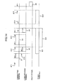
- Fig.6 is a time chart showing the first embodiment;
- Fig.7 is a flowchart showing an operation of a second embodiment;
- Fig.8 is a time chart showing the second embodiment;
- Fig.9 is a flowchart showing an operation of a third embodiment;
- Fig.10 is a time chart showing the third embodiment;
- Fig.11 is a block diagram of a fourth embodiment;
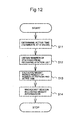
- Fig.12 is a flowchart showing an operation of the fourth embodiment;
- Fig.13 is a flowchart showing an operation of the fourth embodiment; and
- Fig. 14 is a time chart showing a previously described prior art arrangement.
- Embodiments are hereinafter described. For the purpose of easy comprehension, the explanation is made with respect to the data transmission from a first terminal to a second terminal among a plurality of terminals via a relay station.
- A first embodiment is explained.
- The first and the second terminals are described.
- Fig.1 is a block diagram of the first and the second terminals. Fig.2 is a flowchart showing an operation of the first terminal. Fig.3 is a flowchart showing an operation of the second terminals.
- Each of the first and the second terminals is provided with an
antenna 1, a receivingunit 2, a transmitting unit 3, CPU4, and atimer 5, respectively. - An explanation of the first terminal is described below.
- The
CPU 4 starts the timer 5 (111), which identifies whether or not the channel is unused for Time 1 (112). For this identification step, thetimer 5 is started by setting toTime 1 to check unused status on the channel until the expiration is detected (113). - If it is determined that the channel has been busy before detecting the expiration, it proceeds to defer mode (115). While if the expiration is detected with the channel kept unused, the transmitting unit 3 transmits data (114).
- When one or more terminals are waiting transmission data, supposing that all stations start transmitting simultaneously after the elapse of
Time 1, data conflict will be inevitable. In order to reduce such data conflict rate, generally each station is so set to defer for the period determined by adding random period at least toTime 1. - An explanation of the second terminal is described below.
- The
CPU 4 starts thetimer 5 in response to receiving data or control information addressed to its own terminal at the receiving unit 1(121), and defers untilTime 2 expires (122). TheTime 2 is so set to have shorter time interval than that of theaforementioned Time 1. - The
CPU 4 controls the transmitting unit 3 to transmit the control information as a response to the received data or control information (123). - The explanation of the relay station is described below.
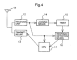
- Fig.4 is a block diagram of the relay station. Fig.5 is a flowchart showing an operation of the relay station.
- In Fig.5, a
reference numeral 11 is an antenna, 12 is a receiving unit, 13 is a transmitting unit, 14 is a judging means, 15 is a timer, 16 is a response detection means, and 17 is a CPU. - The signal from the first terminal received by the
antenna 11 is demodulated into control information or data through the receivingunit 12, then output to the judging means 14. - The judging means 14 determines whether or not the demodulated information is control information transmitted form the first terminal (211). If the information is determined as the control information, it starts the timer 15 (221). The time interval set for the
timer 15 is to be Time 3 that has shorter time interval thanTime 1 and longer time interval thanTime 2. - The response detection means 16 detects the response from the second terminal until the
timer 15 expires (222). In case it detects no response, the second terminal is determined to be in the area which is not connectable to the first terminal, and a signal containing such information is output to the CPU17 (223) . - The
CPU 17 starts to perform representative response to the first terminal in place of the second terminal based on a predetermined procedure (231). - The
CPU 17 representatively responds to the received control information. It determines whether or not the procedure has been finished(232). If it determines that the procedure has not been finished yet, it waits until receiving the next procedure (233). - Upon receiving the next procedure, it representatively responds to the corresponded control information until the procedure is finished. If the procedure is determined to have been finished (232), the process proceeds to relay process.
- At this relay process, the transmitting unit 3 transmits the transmission data of the first terminal (except control information) to the channel again for transferring the transmission data to the second terminal (242) .
- A series of operations are explained as an example combining the first embodiment and the prior art described in the
Reference 1. - In Fig.6,
time intervals Time 1.Time intervals Time 2.Time intervals - After confirming that the channel has been unused for Time 1 (time interval 611), the first terminal transmits
control information 61. - Supposing that the second terminal is out of field supported by the first terminal, the
control information 61 fails to reach the second terminal. - While the relay station receives the
control information 61 from the first terminal, where the judging means 14 performs judgment to start thetimer 15. In case of no response from the second terminal even after the elapse of Time 3 (time interval 616), the response detection means 16 detects expiration of the timer, then proceeding to the representative response. - The relay station serves to respond in place of the second terminal, by which control
information 62 indicating channel connectability is transmitted to the first terminal. - Receiving the
control information 62, the first terminal transmitsdata 63 after the elapse of Time 2 (time interval 617). Upon receiving the data, the relay station transmitscontrol information 64 to the first terminal. - The above correspondence between the relay station and the first terminal is referred to as a first sequence process.
- When the first sequence process is terminated, a second sequence process, i.e., relay process, is started.
- In order to prevent other terminals from starting the respective communication concurrently, the process uses Time 3 for a waiting time until start of relaying.
- The relay station transmits
control information 65 which contains the same information as that transmitted from the first terminal to the second terminal for checking connectability of the transmitting channel. - Upon receiving
control information 66 as a response to thecontrol information 65 from the second terminal, the relay station transmitsdata 67 which is the same as thedata 63 which has been already received thereby to the second terminal. - Upon receiving the
data 67, the second terminal finally transmitscontrol information 68 to terminate the relay process. - The
time intervals Time 2. However they may be set to Time 3, shorter thanTime 1, as far as they serve to prevent other stations from starting the respective data transmission procedures. - Other terminals delay the start of their transmission for the period required to use the channel contained in
control information - The first embodiment provides an advantage to eliminate the need to determine whether the transmitting terminal is able to transmit data directly to its addressed terminal, or relay process is required. This embodiment allows to prevent other terminals from starting their own transmission procedures during relay processing.
- This is the end of the explanation of the first embodiment.
- The second embodiment is described below.
- The second embodiment relates to a relay process in broadcast transmission.
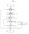
- Fig.7 is a flowchart showing an operation of the second embodiment, which is inserted to a point A of the first embodiment in Fig.5. The second embodiment assumes to have broadcast transmission to a plurality of terminals including the first and the second terminals.
- When the
timer 15 expires, a judging means 14 determines if information from the first terminal is subjected to broadcast transmission (411). If the information is determined to be on broadcast transmission, it starts broadcast relaying (412). The relay station informs a plurality of terminals including the second terminal that broadcast transmission has been executed. - The judging means 14 starts the timer 15 (413) to wait for receiving responses from the terminals including the second terminal (414). The
timer 15 is so set to Time 3. - The response detection means 16 detects whether broadcast relay request has been returned from a certain terminal, In case of no relay request until expiration of the
timer 15, no process is executed, thus returning to the point A. - While in case of receiving the relay request from some terminal before expiration is detected by the response detection means 16 (415), the
CPU 17 serves to transmit the received broadcast packet to the channel via the relay station, assuming that the destination terminal is out of the field supported by the first terminal. - If the destination terminal receives no broadcast transmission from the first terminal but broadcast information from the relay station, it determines to be out of the field supported by the transmitting terminal, thus transmitting the relay request to the relay station.
- The operation of the example combining the second embodiment and the prior art of the
Reference 1 is described in detail. - Fig.8 is a time chart showing the second embodiment.
- In the
Reference 1, the procedure for broadcast counts 0, which is intended for broadcast data transmission only.Broadcast data 71 are transmitted after confirming unused status of the channel for antime interval 711. A conventional method finishes its operation at the above stage, which fails in clarifying as to which station has received the data. - So the relay station defers for Time 3 (time interval 715) after receiving
data 71 from the first terminal, then broadcasts thecontrol information 72 that indicates execution of broadcast transmission to all terminals. This procedure sets the deferring period to Time 3 (time interval 715). However it may be set toTime 2 as far as keeping other terminals from starting their own transmission concurrently. - The relay station defers for the relay request within Time 3 (time interval 712).
- Upon receiving
control information 73 indicating relay request from the second terminal, the relay station transmitsdata 74 containing the receivedbroadcast transmission data 71 to the second terminal, and terminates the operation procedure. - After finishing the transmission, another terminal starts operating its
own transmission procedure 75 after the elapse of at least Time 1 (time interval 714). - The second embodiment provides an advantage to eliminate double transmission of the transmitting terminal in case there is a terminal that cannot be communicated with at least one station.
- This is the end of the explanation of the second embodiment.
- Following description is a program of the present invention to be added to that described in
Reference 1 for realizing the operation shown in Figs. 6 and 7. There is no change in algorithm for the transmitting station. While in the algorithm for the receiving station, the following program is added to that for the receiving station ofReference 1. - If the station is a broadcast receiving station stated in ATB frame and receives no broadcast data prior to receiving ATB,
then transmit RTB after SIFS when CRC was correct. - The relay station is provided with the following bridge algorithm as well as algorithm for the above transmitting and receiving stations.
- If RTS frame is detected but the station is not the destination,
then defer at PIFS. - If CS is not active and CTS frame is not detected,
then transmit CTS frame when the CRC was correct. - If the station receives data frame to be transmitted to the succeeding unicast,
then transmit Ack to be transmitted to transmission queue after SIFS when CRC was correct. - Else If station receives data frame subjected to multicast,
then transmit ATB after PIFS when CRC was correct. - If station receives RTB after SIFS or detects carrier sense,
then transmit received data frame.
The following terms of the program in the present invention correspond to the respective items shown in Fig.7. That is, ATB corresponds to 72R, RTB to 73, and PIFS to 715, respectively. Each definition of those items such as data, DIFS, SIFS, CRC, and the like is equivalent to that of the program described inReference 1.
An explanation of a third embodiment is described.
The third embodiment is a method which detects whether or not the response is made at every receipt of packet, and in case of no response, the received packet is relayed.
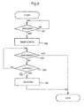
Fig.9 is a flowchart showing an operation of the third embodiment.
Upon receiving data from the first terminal via a receiving unit 12 (151), the judging means 14 starts the timer 15 (152). In this operation thetimer 15 is so set to Time 3 until it expires.
If receiving the response from the second terminal before the response detection means 16 detects expiration of the timer 15 (153), the operation is terminated.
If receiving no response from the second terminal before the response detection means 16 detects the expiration (154), theCPU 17 transmits the received packet on the channel again (155), assuming that the second terminal is out of the field supported by the first terminal. Then the packet is transferred via the relay station between the first and the second terminals.
As aforementioned, in the third embodiment, transmission data and control information transmitted for data transmission are not distinguished. In case the transmitting terminal further transmits additional control information to the response from the receiving terminal, it is assumed to be in the response to the preceding correspondence, thus, repeating the same process as shown in Fig.9.
The operation of the third embodiment is described in more detail.
Fig. 10 is a time chart showing the third embodiment. In Fig.10, atime interval 911 corresponds toTime Time 2, and 912 to Time 3.
When the first terminal transmitscontrol information 91, the relay station receives thecontrol information 91 to start thetimer 15, and defers for Time 3 (time interval 912). Incase control information 93 is not returned from the second terminal until the expiration of Time 3, the relay station determines that the second terminal is out of the field directly supported by the first terminal, and transmitscontrol information 92, which is the same as thecontrol information 91 to the second terminal.
Upon receiving thecontrol information 92, the second terminal transmitscontrol information 93 corresponding thereto.
Receiving thecontrol information 93 from the second terminal, the relay station transmits it ascontrol information 94 to the first terminal.
Receiving thecontrol information 94, the first terminal transmitsdata 95. Receiving thedata 95, the relay station relays thedata 95 asdata 96 to the second terminal.
The second terminal receives thedata 96, and transmitscontrol information 97.
The relay station receives thecontrol information 97, and transmitscontrol information 98.
Time intervals
This is the end of the explanation of the third embodiment.
An explanation of a fourth embodiment is described below.
In the fourth embodiment provided with only terminals and no relay station, a certain terminal is selected to have a relay function allocated thereto.
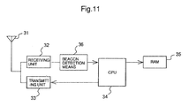
Fig.11 is a block diagram of each terminal. Figs. 12 and 13 are flowcharts showing the operation of the embodiment.
Each terminal obtains active period of its station with CPU 34 (511). The active period refers to the time interval from starting the terminal to the present time, which may have the upper limit if it will increase to substantially a great value.
The process is executed to count the number of stations currently contained in a receiving station list stored in RAM 35 (512). The receiving station list refers to the list which contains address of the terminal which has transmitted a Beacon and weighting information thereof (described later).
TheCPU 34 calculates the weighting information by multiplying the active period by the number of stations(513). A Beacon containing the weighting information is broadcasted from the transmitting unit 33(514). The above process is repeatedly executed.
When the Beacon detection means 36 detects the receipt of the Beacon, the following processes are executed (521).
TheCPU 34 determines whether the terminal corresponding to received Beacon has been already listed in the receiving station list stored in the RAM 35 (522). If it is determined not to have been listed, the address of the terminal is added to the receiving station list (523). The weighting information contained in the received Beacon is extracted. The oldest weighting information among those obtained n times in the past is erased. It then adds the weight and address of the newly received Beacon for updating the weighting list.
It is judged whether or not the address of the subject station is contained in n times of the weight list in the past (525). If it is not contained and yet the station employs the function of the relay station, the operation is terminated (528).
If it is contained, it is judged whether or not the subject station has the greatest weight among (n-1) weights as a result of excluding its own weight from the weight list obtained n times in the past (526). In case it is determined to have the greatest weight, it is regarded as a relay station (527) for executing relay process described in the first, second, and third embodiments.
The fourth embodiment provides no specific relay station, in which the terminal that can relay signals of the stations as many as possible is selected to have a relay function allocated thereto. This provides an effective relay function in distributed network.
Claims (23)
- An access method used for relaying and broadcasting a broadcast data in a data transmission system having a procedure to exchange control information at least one time between terminals to transmit not broadcast a data, said access method characterized in comprising:a step of broadcasting said broadcast data to a plurality of terminals in a first terminal;a step of broadcasting said broadcast information that informs fact of completion of broadcasting to said terminals when said broadcast data has been received in a relay station;a step of transmitting a relay request to said relay station when having received only said broadcast information in each of said terminals;a step of detecting said relay request during a preset detection time interval from the time when said broadcast information had been transmitted in said relay station; anda step of transferring said broadcast data to a terminal that had transmitted said relay request when said relay request has been detected during said detection time interval in said relay station.
- The access method of claim 1, characterized in that said detection time interval is set so as to be:shorter than a time needed for confirming channel occupation status before start of transmission by said first terminal; andlonger than a time from reception of said control information to transmission of a response to said control information.
- An access system used for relaying and broadcasting a broadcast data in a data transmission system having a procedure to exchange control information at least one time between terminals to transmit not broadcast a data, said access system characterized in comprising:a first terminal having means (4) for broadcasting said broadcast data;a relay station havingmeans (17) for broadcasting a broadcast information that informs fact of completion of broadcasting when said broadcast data has been received, means (15, 16) for detecting a relay request during a preset detection time interval from the time when said broadcast information had been transmitted, and means (17) for broadcasting said broadcast data to a terminal that had transmitted said relay request when said relay request has been detected during said detection time interval; andeach of said terminals having means (4) for transmitting said relay request to said relay station when having received only said broadcast information.
- The relay station of claim 3, characterized in further comprising said detection means (15, 16) having said detection time interval that is set so as to be:shorter than a time needed for confirming channel occupation status before start of transmission by said first terminal; andlonger than a time from reception of said control information to transmission of a response to said control information between said first terminal and said second terminal.
- An access method used for relaying and transferring data from a first terminal to a second terminal using a relay station when the data cannot be directly transmitted from said first terminal to said second terminal in a data transmission system having a procedure to exchange control information at least one time between said first terminal and said second terminal to transmit said data from said first terminal to said second terminal, said access method characterized in comprising:a step of receiving said control information transmitted from said first terminal in said relay station;a step of detecting a response of said control information from said second terminal during a preset detection time interval from a time of reception of said control information in said relay station;a first sequence step of exchanging, instead of said second terminal, control information with said first terminal and receiving said data from said first terminal when said response has not been detected during said detection time interval in said relay station; anda second sequence step of exchanging said control information with said second terminal and transferring said data to said second terminal in said relay station.
- The access method of claim 5, characterized in that said detection time interval is set so as to be:shorter than a time needed for confirming channel occupation status before start of transmission by said first terminal; andlonger than a time from reception of said control information to transmission of a response to said control information.
- The access method of claim 5, characterized in that a waiting time interval from said first sequence step to said second sequence step is set so as to be:shorter than a time needed for confirming channel occupation status before start of transmission by said first terminal; andlonger than a time from reception of said control information to transmission of a response to said control information.
- An access method used for relaying and transferring data from a first terminal to a second terminal using a relay station when the data cannot be directly transmitted from said first terminal to said second terminal in data information transmission system having a procedure to exchange control information at least one time between said first terminal and said second terminal to transmit said data information from said first terminal to said second terminal, said access method characterized in comprising:a step of receiving said information selected from the group consisting of said control information and said data information transmitted from said first terminal in said relay station;a step of detecting existence of a response of said information from said second terminal during a preset detection time interval from a time of reception of said information in said relay station;a step of transferring said information to said second terminal when said response has not been detected during said detection time interval in said relay station.
- The access method of claim 8, characterized in that said detection time interval is set so as to be:shorter than a time needed for confirming channel occupation status before start of transmission by said first terminal; andlonger than a time from reception of said control information to transmission of a response to said control information.
- An access method of a transmission system having a plurality of terminals, characterized in comprising:a step of calculating weight based on a product of an own terminal's active period and a number of terminals that have been received in each of said terminals;a step of generating a weighting information by adding own terminal's address to said weight;a step of broadcasting said weighting information in each terminal;a step of receiving said weighting information and creating a weighting information list consisting of upper n weighting information in each of said terminals; anda step of functioning own terminal as a relay station when own terminal has biggest weight based on said weighting information list in each of said terminals.
- The access method of claim 10, characterized in further comprising a step of suspending a function as a relay station when own terminal is not included in said weighting information list and own terminal is functioning as a relay station.
- The access method of claim 10, transferring data from a first terminal to a second terminal using a third terminal as a relay station when said data cannot be directly transmitted from said first terminal to said second terminal in a data transmission system having a procedure to exchange control information at least one time between said first terminal and said second terminal to transmit said data from said first terminal to said second terminal, said access method characterized in comprising:a step of receiving said control information transmitted from said first terminal in said third terminal;a step of detecting existence of control information from said second terminal during a preset detection time interval from a time of reception of said control information in said third terminal;a first sequence step of exchanging, instead of said second terminal, said control information with said first terminal and receiving said data from said first terminal when said control information has not been detected during said detection time interval in said third terminal; anda second sequence step of exchanging said control information with said second terminal and transferring said data to said second terminal in said third terminal.
- The access method of claim 12, characterized in that said detection time interval is set so as to be:shorter than a time needed for confirming channel occupation status before start of transmission by said first terminal; andlonger than a time from reception of said control information to transmission of a response to said control information.
- The access method of claim 12, characterized in that a weighting time interval between said first sequence step and said second sequence step is set so as to be:shorter than a time needed for confirming channel occupation status before start of transmission by said first terminal; andlonger than a time from reception of said control information to transmission of a response to said control information.
- The access method of claim 10, characterized in that a second terminal functions as a relay station when a first terminal broadcasts broadcast data to a plurality of terminals, said access method comprising:a step of broadcasting said broadcast data to said terminals in said first terminal;a step of broadcasting a broadcast information that informs fact of completion of broadcasting to said terminals when said broadcast data has been received in said second terminal;a step of transmitting a relay request to said second terminal when having received only said broadcast information in each of said terminals;a step of detecting said relay request during a preset detection time interval from the time when said broadcast information had been transmitted in said second terminal; anda step of transferring said broadcast data to a terminal that had transmitted said relay request when said relay request has been detected during said detection time interval in said second terminal.
- The access method of claim 10, transferring data information from a first terminal to a second terminal using a third terminal as a relay station when said data information cannot be directly transmitted from said first terminal to said second terminal in a data transmission system having a procedure to exchange control information at least one time between said first terminal and said second terminal to transmit said data from said first terminal to said second terminal, said access method characterized in comprising:a step of receiving information selected from the group consisting of said control information and said data information transmitted from said first terminal in said third terminal;a step of detecting a response of said information from said second terminal during a preset detection time interval from a time of reception of said information in said third terminal;a step of transferring said information when said response has not been detected during said detection time interval in said third terminal.
- The access method of claim 16, characterized in that said detection time interval is set so as to be:shorter than a time needed for confirming channel occupation status before start of transmission by said first terminal; andlonger than a time from reception of said control information to transmission of a response to said control information.
- A relay station for relaying and transferring data from a first terminal to a second terminal when said data cannot be directly transmitted from said first terminal to said second terminal in a data transmission system having a procedure to exchange control information at least one time between said first terminal and said second terminal to transmit said data from said first terminal to said second terminal, said relay station characterized in comprising:means (14) for receiving and judging said control information transmitted from said first terminal and judging said control information from among said information;means (15, 16) for detecting a response of said control information from said second terminal during a preset detection time interval from a time of reception of said control information;means (17) for exchanging, instead of said second terminal, said control information with said first terminal, receiving said data from said first terminal, exchanging said control information with said second terminal and transferring said data to said second terminal when said response has not been detected during said detection time interval.
- The relay station of claim 18, characterized in further comprising said detection means (15, 16) having said detection time interval that is set so as to be:shorter than a time needed for confirming channel occupation status before start of transmission by said first terminal; andlonger than a time from reception of said control information to transmission of a response to said control information between said first terminal and said second terminal.
- A relay station for relaying and transferring data information from a first terminal to a second terminal when said data information cannot be directly transmitted from said first terminal to said second terminal in a data transmission system having a procedure to exchange control information at least one time between said first terminal and said second terminal to transmit said data information from said first terminal to said second terminal, said relay station characterized in comprising:means (14) for receiving information selected from the group consisting of said control information and said data information transmitted from said first terminal;means (15, 16) for detecting a response of said information from said second terminal during a preset detection time interval from a time of reception of said information;means (17) for transferring said information to said second terminal when said response has not been detected during said detection time interval.
- The relay station of claim 20, characterized in further comprising said detection means (15, 16) having said detection time interval that is set so as to be:shorter than a time needed for confirming channel occupation status before start of transmission by said first terminal; andlonger than a time from reception of said control information to transmission of a response to said control information between said first terminal and said second terminal.
- A terminal device used for mobile communication systems characterized in comprising:means (4) for calculating weight based on a product of an own terminal's active period and a number of terminals that have been received and generating weighting information by adding own terminal's address to said weight;means (33) for broadcasting said weighting information;means (36, 34) for receiving said weighting information from other terminals and creating a weighting information list consisting of upper n weights;means (34) for setting own terminal as a relay station when own terminal has biggest weight among weights stored in said weighting information list
- The terminal device of claim 22, characterized in further comprising said setting means (34) for suspending a function as a relay station when own terminal is not included in said weighting information list and own terminal is functioning as a relay station.
Applications Claiming Priority (2)
| Application Number | Priority Date | Filing Date | Title |
|---|---|---|---|
| JP7829694A JP2591467B2 (en) | 1994-04-18 | 1994-04-18 | Access method |
| EP95302549A EP0680177B1 (en) | 1994-04-18 | 1995-04-18 | Access method and a relay station and terminals thereof |
Related Parent Applications (1)
| Application Number | Title | Priority Date | Filing Date |
|---|---|---|---|
| EP95302549A Division EP0680177B1 (en) | 1994-04-18 | 1995-04-18 | Access method and a relay station and terminals thereof |
Publications (2)
| Publication Number | Publication Date |
|---|---|
| EP1701482A1 true EP1701482A1 (en) | 2006-09-13 |
| EP1701482B1 EP1701482B1 (en) | 2007-08-15 |
Family
ID=13657971
Family Applications (2)
| Application Number | Title | Priority Date | Filing Date |
|---|---|---|---|
| EP95302549A Expired - Lifetime EP0680177B1 (en) | 1994-04-18 | 1995-04-18 | Access method and a relay station and terminals thereof |
| EP06101229A Expired - Lifetime EP1701482B1 (en) | 1994-04-18 | 1995-04-18 | Access method and system for relaying and broadcasting broadcast data |
Family Applications Before (1)
| Application Number | Title | Priority Date | Filing Date |
|---|---|---|---|
| EP95302549A Expired - Lifetime EP0680177B1 (en) | 1994-04-18 | 1995-04-18 | Access method and a relay station and terminals thereof |
Country Status (3)
| Country | Link |
|---|---|
| US (1) | US5621732A (en) |
| EP (2) | EP0680177B1 (en) |
| JP (1) | JP2591467B2 (en) |
Families Citing this family (113)
| Publication number | Priority date | Publication date | Assignee | Title |
|---|---|---|---|---|
| US6160992A (en) * | 1996-10-31 | 2000-12-12 | Lucent Technologies Inc. | Method and system for communicating with remote units in a communication system |
| JP3183224B2 (en) * | 1997-07-31 | 2001-07-09 | 日本電気株式会社 | Communication control method for multiple network terminals and apparatus therefor |
| DE19748681A1 (en) * | 1997-11-04 | 1999-05-12 | Innotech Gmbh | Network for the transmission of data with mobile data transmission devices |
| US6215799B1 (en) | 1997-11-24 | 2001-04-10 | 3Com Corporation | Analog telephone to ISDN interface apparatus and method therefor |
| JP3430057B2 (en) * | 1999-02-03 | 2003-07-28 | 松下電器産業株式会社 | Wireless communication system |
| US6628946B1 (en) * | 1999-05-20 | 2003-09-30 | Telefonaktiebolaget Lm Ericsson (Publ) | Method and apparatus for broadcasting system information in a cellular communications network |
| US6363062B1 (en) * | 1999-06-08 | 2002-03-26 | Caly Corporation | Communications protocol for packet data particularly in mesh topology wireless networks |
| JP4116212B2 (en) * | 1999-12-28 | 2008-07-09 | 株式会社東芝 | COMMUNICATION DEVICE AND ITS CONTROL METHOD |
| US7782363B2 (en) * | 2000-06-27 | 2010-08-24 | Front Row Technologies, Llc | Providing multiple video perspectives of activities through a data network to a remote multimedia server for selective display by remote viewing audiences |
| US7812856B2 (en) | 2000-10-26 | 2010-10-12 | Front Row Technologies, Llc | Providing multiple perspectives of a venue activity to electronic wireless hand held devices |
| US7149549B1 (en) | 2000-10-26 | 2006-12-12 | Ortiz Luis M | Providing multiple perspectives for a venue activity through an electronic hand held device |
| US7630721B2 (en) | 2000-06-27 | 2009-12-08 | Ortiz & Associates Consulting, Llc | Systems, methods and apparatuses for brokering data between wireless devices and data rendering devices |
| US8583027B2 (en) | 2000-10-26 | 2013-11-12 | Front Row Technologies, Llc | Methods and systems for authorizing computing devices for receipt of venue-based data based on the location of a user |
| US7796162B2 (en) * | 2000-10-26 | 2010-09-14 | Front Row Technologies, Llc | Providing multiple synchronized camera views for broadcast from a live venue activity to remote viewers |
| US20030112354A1 (en) * | 2001-12-13 | 2003-06-19 | Ortiz Luis M. | Wireless transmission of in-play camera views to hand held devices |
| US6577609B2 (en) * | 2000-09-29 | 2003-06-10 | Symbol Technologies, Inc. | Local addressing of mobile units in a WLAN with multicast packet addressing |
| KR100525381B1 (en) * | 2000-10-14 | 2005-11-02 | 엘지전자 주식회사 | Method for system information broadcast in 3GPP(The third generation partnership project |
| JP3796537B2 (en) | 2000-10-24 | 2006-07-12 | 独立行政法人情報通信研究機構 | Wireless communication terminal, wireless communication method, and information recording medium |
| US6807165B2 (en) | 2000-11-08 | 2004-10-19 | Meshnetworks, Inc. | Time division protocol for an ad-hoc, peer-to-peer radio network having coordinating channel access to shared parallel data channels with separate reservation channel |
| US6873839B2 (en) | 2000-11-13 | 2005-03-29 | Meshnetworks, Inc. | Prioritized-routing for an ad-hoc, peer-to-peer, mobile radio access system |
| US7072650B2 (en) * | 2000-11-13 | 2006-07-04 | Meshnetworks, Inc. | Ad hoc peer-to-peer mobile radio access system interfaced to the PSTN and cellular networks |
| US7301946B2 (en) * | 2000-11-22 | 2007-11-27 | Cisco Technology, Inc. | System and method for grouping multiple VLANs into a single 802.11 IP multicast domain |
| US7251232B1 (en) | 2000-11-22 | 2007-07-31 | Cisco Technology, Inc. | Point-controlled contention arbitration in multiple access wireless LANs |
| US7151769B2 (en) * | 2001-03-22 | 2006-12-19 | Meshnetworks, Inc. | Prioritized-routing for an ad-hoc, peer-to-peer, mobile radio access system based on battery-power levels and type of service |
| GB2375015A (en) * | 2001-04-27 | 2002-10-30 | Ericsson Telefon Ab L M | Communications networks |
| JP2004531971A (en) * | 2001-06-14 | 2004-10-14 | メッシュネットワークス インコーポレーティッド | A routing protocol embedded under the internet protocol routing layer of the software architecture protocol stack in mobile ad hoc networks |
| US7072323B2 (en) * | 2001-08-15 | 2006-07-04 | Meshnetworks, Inc. | System and method for performing soft handoff in a wireless data network |
| US7206294B2 (en) * | 2001-08-15 | 2007-04-17 | Meshnetworks, Inc. | Movable access points and repeaters for minimizing coverage and capacity constraints in a wireless communications network and a method for using the same |
| US7349380B2 (en) * | 2001-08-15 | 2008-03-25 | Meshnetworks, Inc. | System and method for providing an addressing and proxy scheme for facilitating mobility of wireless nodes between wired access points on a core network of a communications network |
| US7613458B2 (en) * | 2001-08-28 | 2009-11-03 | Meshnetworks, Inc. | System and method for enabling a radio node to selectably function as a router in a wireless communications network |
| JP2003078528A (en) * | 2001-09-04 | 2003-03-14 | Omron Corp | Radio equipment and communication system using the same |
| US7145903B2 (en) * | 2001-09-06 | 2006-12-05 | Meshnetworks, Inc. | Multi-master bus architecture for system-on-chip designs |
| JP4139775B2 (en) * | 2001-09-25 | 2008-08-27 | メシュネットワークス、インコーポレイテッド | Systems and methods employing algorithms and protocols for operating Carrier Sense Multiple Access (CSMA) protocols in wireless networks |
| US6754188B1 (en) | 2001-09-28 | 2004-06-22 | Meshnetworks, Inc. | System and method for enabling a node in an ad-hoc packet-switched wireless communications network to route packets based on packet content |
| US6768730B1 (en) | 2001-10-11 | 2004-07-27 | Meshnetworks, Inc. | System and method for efficiently performing two-way ranging to determine the location of a wireless node in a communications network |
| US6982982B1 (en) | 2001-10-23 | 2006-01-03 | Meshnetworks, Inc. | System and method for providing a congestion optimized address resolution protocol for wireless ad-hoc networks |
| US6771666B2 (en) | 2002-03-15 | 2004-08-03 | Meshnetworks, Inc. | System and method for trans-medium address resolution on an ad-hoc network with at least one highly disconnected medium having multiple access points to other media |
| US6937602B2 (en) * | 2001-10-23 | 2005-08-30 | Meshnetworks, Inc. | System and method for providing a congestion optimized address resolution protocol for wireless ad-hoc networks |
| US7181214B1 (en) | 2001-11-13 | 2007-02-20 | Meshnetworks, Inc. | System and method for determining the measure of mobility of a subscriber device in an ad-hoc wireless network with fixed wireless routers and wide area network (WAN) access points |
| US7136587B1 (en) | 2001-11-15 | 2006-11-14 | Meshnetworks, Inc. | System and method for providing simulated hardware-in-the-loop testing of wireless communications networks |
| US6728545B1 (en) | 2001-11-16 | 2004-04-27 | Meshnetworks, Inc. | System and method for computing the location of a mobile terminal in a wireless communications network |
| US7239648B1 (en) | 2001-11-27 | 2007-07-03 | Marvell International Ltd. | Extension mode for wireless lans complying with short interframe space requirement |
| US7221686B1 (en) | 2001-11-30 | 2007-05-22 | Meshnetworks, Inc. | System and method for computing the signal propagation time and the clock correction for mobile stations in a wireless network |
| US7190672B1 (en) | 2001-12-19 | 2007-03-13 | Meshnetworks, Inc. | System and method for using destination-directed spreading codes in a multi-channel metropolitan area wireless communications network |
| US7106707B1 (en) | 2001-12-20 | 2006-09-12 | Meshnetworks, Inc. | System and method for performing code and frequency channel selection for combined CDMA/FDMA spread spectrum communication systems |
| US7180875B1 (en) | 2001-12-20 | 2007-02-20 | Meshnetworks, Inc. | System and method for performing macro-diversity selection and distribution of routes for routing data packets in Ad-Hoc networks |
| US7280545B1 (en) | 2001-12-20 | 2007-10-09 | Nagle Darragh J | Complex adaptive routing system and method for a nodal communication network |
| US7072618B1 (en) | 2001-12-21 | 2006-07-04 | Meshnetworks, Inc. | Adaptive threshold selection system and method for detection of a signal in the presence of interference |
| US6674790B1 (en) | 2002-01-24 | 2004-01-06 | Meshnetworks, Inc. | System and method employing concatenated spreading sequences to provide data modulated spread signals having increased data rates with extended multi-path delay spread |
| US6862456B2 (en) * | 2002-03-01 | 2005-03-01 | Cognio, Inc. | Systems and methods for improving range for multicast wireless communication |
| EP1769585A4 (en) | 2002-03-01 | 2009-12-02 | Ipr Licensing Inc | System and method for joint maximal ratio combining using time-domain based signal processing |
| US6687492B1 (en) * | 2002-03-01 | 2004-02-03 | Cognio, Inc. | System and method for antenna diversity using joint maximal ratio combining |
| US6785520B2 (en) | 2002-03-01 | 2004-08-31 | Cognio, Inc. | System and method for antenna diversity using equal power joint maximal ratio combining |
| US7058018B1 (en) | 2002-03-06 | 2006-06-06 | Meshnetworks, Inc. | System and method for using per-packet receive signal strength indication and transmit power levels to compute path loss for a link for use in layer II routing in a wireless communication network |
| US6617990B1 (en) | 2002-03-06 | 2003-09-09 | Meshnetworks | Digital-to-analog converter using pseudo-random sequences and a method for using the same |
| US7130289B2 (en) * | 2002-03-14 | 2006-10-31 | Airmagnet, Inc. | Detecting a hidden node in a wireless local area network |
| DE60321895D1 (en) | 2002-03-15 | 2008-08-14 | Meshnetworks Inc | SYSTEM AND METHOD FOR SELF-CONFIGURATION AND DISCOVERY OF IP-TO-MAC ADDRESS PICTURES AND THE GATEWAY PRESENCE |
| US6904021B2 (en) | 2002-03-15 | 2005-06-07 | Meshnetworks, Inc. | System and method for providing adaptive control of transmit power and data rate in an ad-hoc communication network |
| US6871049B2 (en) * | 2002-03-21 | 2005-03-22 | Cognio, Inc. | Improving the efficiency of power amplifiers in devices using transmit beamforming |
| US6987795B1 (en) | 2002-04-08 | 2006-01-17 | Meshnetworks, Inc. | System and method for selecting spreading codes based on multipath delay profile estimation for wireless transceivers in a communication network |
| US7200149B1 (en) | 2002-04-12 | 2007-04-03 | Meshnetworks, Inc. | System and method for identifying potential hidden node problems in multi-hop wireless ad-hoc networks for the purpose of avoiding such potentially problem nodes in route selection |
| US6580981B1 (en) | 2002-04-16 | 2003-06-17 | Meshnetworks, Inc. | System and method for providing wireless telematics store and forward messaging for peer-to-peer and peer-to-peer-to-infrastructure a communication network |
| US7107498B1 (en) | 2002-04-16 | 2006-09-12 | Methnetworks, Inc. | System and method for identifying and maintaining reliable infrastructure links using bit error rate data in an ad-hoc communication network |
| US7142524B2 (en) * | 2002-05-01 | 2006-11-28 | Meshnetworks, Inc. | System and method for using an ad-hoc routing algorithm based on activity detection in an ad-hoc network |
| US7382756B2 (en) * | 2002-05-04 | 2008-06-03 | Broadcom Corporation | Integrated user and radio management in a wireless network environment |
| US6970444B2 (en) | 2002-05-13 | 2005-11-29 | Meshnetworks, Inc. | System and method for self propagating information in ad-hoc peer-to-peer networks |
| US7284268B2 (en) | 2002-05-16 | 2007-10-16 | Meshnetworks, Inc. | System and method for a routing device to securely share network data with a host utilizing a hardware firewall |
| US7016306B2 (en) * | 2002-05-16 | 2006-03-21 | Meshnetworks, Inc. | System and method for performing multiple network routing and provisioning in overlapping wireless deployments |
| US7167715B2 (en) * | 2002-05-17 | 2007-01-23 | Meshnetworks, Inc. | System and method for determining relative positioning in AD-HOC networks |
| US7106703B1 (en) | 2002-05-28 | 2006-09-12 | Meshnetworks, Inc. | System and method for controlling pipeline delays by adjusting the power levels at which nodes in an ad-hoc network transmit data packets |
| US6744766B2 (en) | 2002-06-05 | 2004-06-01 | Meshnetworks, Inc. | Hybrid ARQ for a wireless Ad-Hoc network and a method for using the same |
| US7610027B2 (en) * | 2002-06-05 | 2009-10-27 | Meshnetworks, Inc. | Method and apparatus to maintain specification absorption rate at a wireless node |
| US6687259B2 (en) | 2002-06-05 | 2004-02-03 | Meshnetworks, Inc. | ARQ MAC for ad-hoc communication networks and a method for using the same |
| US7054126B2 (en) * | 2002-06-05 | 2006-05-30 | Meshnetworks, Inc. | System and method for improving the accuracy of time of arrival measurements in a wireless ad-hoc communications network |
| AU2003238968A1 (en) * | 2002-06-11 | 2003-12-22 | Meshnetworks, Inc. | System and method for multicast media access in ad-hoc communication networks |
| US7215638B1 (en) | 2002-06-19 | 2007-05-08 | Meshnetworks, Inc. | System and method to provide 911 access in voice over internet protocol systems without compromising network security |
| US7072432B2 (en) * | 2002-07-05 | 2006-07-04 | Meshnetworks, Inc. | System and method for correcting the clock drift and maintaining the synchronization of low quality clocks in wireless networks |
| US7796570B1 (en) | 2002-07-12 | 2010-09-14 | Meshnetworks, Inc. | Method for sparse table accounting and dissemination from a mobile subscriber device in a wireless mobile ad-hoc network |
| US7046962B1 (en) | 2002-07-18 | 2006-05-16 | Meshnetworks, Inc. | System and method for improving the quality of range measurement based upon historical data |
| US7042867B2 (en) * | 2002-07-29 | 2006-05-09 | Meshnetworks, Inc. | System and method for determining physical location of a node in a wireless network during an authentication check of the node |
| US7522537B2 (en) * | 2003-01-13 | 2009-04-21 | Meshnetworks, Inc. | System and method for providing connectivity between an intelligent access point and nodes in a wireless network |
| WO2004084022A2 (en) * | 2003-03-13 | 2004-09-30 | Meshnetworks, Inc. | Real-time system and method for computing location of mobile subcriber in a wireless ad-hoc network |
| US7171220B2 (en) * | 2003-03-14 | 2007-01-30 | Meshnetworks, Inc. | System and method for analyzing the precision of geo-location services in a wireless network terminal |
| US20040196812A1 (en) * | 2003-04-07 | 2004-10-07 | Instant802 Networks Inc. | Multi-band access point with shared processor |
| US7397785B2 (en) * | 2003-05-28 | 2008-07-08 | Nokia Corporation | Method for enhancing fairness and performance in a multihop ad hoc network and corresponding system |
| EP1652207A4 (en) * | 2003-06-05 | 2011-12-28 | Meshnetworks Inc | System and method for determining synchronization point in ofdm modems for accurate time of flight measurement |
| WO2004110082A1 (en) * | 2003-06-05 | 2004-12-16 | Meshnetworks, Inc. | System and method for determining location of a device in a wireless communication network |
| US7734809B2 (en) * | 2003-06-05 | 2010-06-08 | Meshnetworks, Inc. | System and method to maximize channel utilization in a multi-channel wireless communication network |
| WO2004114690A1 (en) * | 2003-06-05 | 2004-12-29 | Meshnetworks, Inc. | Optimal routing in ad hac wireless communication network |
| EP1632093A2 (en) * | 2003-06-06 | 2006-03-08 | Meshnetworks, Inc. | System and method for identifying the floor number where a firefighter in need of help is located using received signal strength indicator and signal propagation time |
| WO2004109474A2 (en) * | 2003-06-06 | 2004-12-16 | Meshnetworks, Inc. | System and method for characterizing the quality of a link in a wireless network |
| WO2004109473A2 (en) | 2003-06-06 | 2004-12-16 | Meshnetworks, Inc. | System and method to provide fairness and service differentiation in ad-hoc networks |
| EP1632044B1 (en) * | 2003-06-06 | 2011-10-19 | Meshnetworks, Inc. | Method to improve the overall performance of a wireless communication network |
| KR100539980B1 (en) * | 2003-08-13 | 2005-12-29 | 삼성전자주식회사 | Method for transmitting a beacon and apparatus for performing the same, method for transmitting/receiving a frame and apparatus for performing the same |
| EP1665668B1 (en) * | 2003-09-08 | 2012-10-10 | Philips Intellectual Property & Standards GmbH | Method of providing a medium access protocol |
| SE0302654D0 (en) * | 2003-10-06 | 2003-10-06 | Ericsson Telefon Ab L M | Method and arrangement in a telecommunication system |
| US7167463B2 (en) * | 2004-10-07 | 2007-01-23 | Meshnetworks, Inc. | System and method for creating a spectrum agile wireless multi-hopping network |
| US7382758B2 (en) * | 2004-11-30 | 2008-06-03 | Motorola, Inc. | Medium access control for simultaneous channel communications |
| JP2006165623A (en) * | 2004-12-02 | 2006-06-22 | Nec Access Technica Ltd | Radio relay system, radio client, radio relay method and radio relay program |
| JP4911970B2 (en) | 2005-12-20 | 2012-04-04 | キヤノン株式会社 | Base station control method and base station |
| TWI392277B (en) * | 2006-09-29 | 2013-04-01 | Koninkl Philips Electronics Nv | Automatic partner selection in the cooperative mac protocol |
| EP1924009B1 (en) * | 2006-11-20 | 2009-05-20 | NTT DoCoMo Inc. | Relay apparatus for relaying a data packet to be transmitted from a first partner transceiver to a second partner transceiver |
| US8144723B2 (en) * | 2006-12-11 | 2012-03-27 | New Jersey Institute Of Technology | Method and system for stable throughput of cognitive radio |
| US8000283B2 (en) * | 2007-03-07 | 2011-08-16 | Motorola Solutions, Inc. | Method and apparatus for relay station neighbor discovery |
| US7873020B2 (en) | 2007-10-01 | 2011-01-18 | Cisco Technology, Inc. | CAPWAP/LWAPP multicast flood control for roaming clients |
| US8279794B2 (en) * | 2008-09-24 | 2012-10-02 | Qualcomm Incorporated | Opportunistic data forwarding and dynamic reconfiguration in wireless local area networks |
| JP5344986B2 (en) * | 2009-04-30 | 2013-11-20 | 株式会社エヌ・ティ・ティ・ドコモ | Wireless relay station |
| CN102804907B (en) * | 2009-06-19 | 2015-07-15 | 黑莓有限公司 | Downlink transmissions for type 2 relay |
| EP2443779B1 (en) | 2009-06-19 | 2020-08-05 | BlackBerry Limited | Uplink transmissions for type 2 relay |
| JP5482353B2 (en) * | 2009-07-06 | 2014-05-07 | 株式会社リコー | Relay device, relay method and program |
| JP5669178B2 (en) * | 2010-08-23 | 2015-02-12 | Necプラットフォームズ株式会社 | Communication control method and wireless communication apparatus |
| CN102404804B (en) * | 2011-09-26 | 2014-05-07 | 北京航空航天大学 | Transmission method of MAC (Media Access Control) layer in multi-relay competitive cooperative communication |
| JP7279388B2 (en) * | 2019-02-12 | 2023-05-23 | 日本電気株式会社 | Router system and packet transmission determination method |
Citations (7)
| Publication number | Priority date | Publication date | Assignee | Title |
|---|---|---|---|---|
| US3659085A (en) * | 1970-04-30 | 1972-04-25 | Sierra Research Corp | Computer determining the location of objects in a coordinate system |
| US4230989A (en) * | 1979-05-11 | 1980-10-28 | Engineered Systems, Inc. | Communications system with repeater stations |
| DE3528886A1 (en) * | 1985-08-12 | 1987-02-19 | Siemens Ag | Radiotelephony system |
| EP0523687A2 (en) * | 1991-07-18 | 1993-01-20 | Fujitsu Limited | Mobile telecommunication system having an expanded operational zone |
| EP0532485A2 (en) * | 1991-09-05 | 1993-03-17 | Telefonaktiebolaget L M Ericsson | Adaptive resource allocation in a mobile telephone system |
| EP0544337A1 (en) * | 1991-11-27 | 1993-06-02 | Symbol Technologies, Inc. | Packet data communications |
| DE4224422A1 (en) * | 1992-07-24 | 1994-01-27 | Sel Alcatel Ag | VHF relay radio system - enables broadcasting station to reach any other station directly using integrated repeaters |
Family Cites Families (7)
| Publication number | Priority date | Publication date | Assignee | Title |
|---|---|---|---|---|
| US3955140A (en) * | 1975-05-20 | 1976-05-04 | Public Systems, Inc. | Mobile radio extension unit with punch through operation |
| US4539706A (en) * | 1983-02-03 | 1985-09-03 | General Electric Company | Mobile vehicular repeater system which provides up-link acknowledgement signal to portable transceiver at end of transceiver transmission |
| DE3337648A1 (en) * | 1983-10-17 | 1987-02-26 | Licentia Gmbh | Radio network with a multiplicity of mobile stations |
| US4718081A (en) * | 1986-11-13 | 1988-01-05 | General Electric Company | Method and apparatus for reducing handoff errors in a cellular radio telephone communications system |
| US4882765A (en) * | 1987-05-22 | 1989-11-21 | Maxwell Ray F | Data transmission system |
| JP2887815B2 (en) * | 1990-08-08 | 1999-05-10 | アイシン精機株式会社 | Mobile station position monitoring system |
| US5434490A (en) * | 1992-07-31 | 1995-07-18 | Daifuku Co., Ltd. | Article transport system |
-
1994
- 1994-04-18 JP JP7829694A patent/JP2591467B2/en not_active Expired - Fee Related
-
1995
- 1995-04-18 EP EP95302549A patent/EP0680177B1/en not_active Expired - Lifetime
- 1995-04-18 US US08/423,105 patent/US5621732A/en not_active Expired - Lifetime
- 1995-04-18 EP EP06101229A patent/EP1701482B1/en not_active Expired - Lifetime
Patent Citations (7)
| Publication number | Priority date | Publication date | Assignee | Title |
|---|---|---|---|---|
| US3659085A (en) * | 1970-04-30 | 1972-04-25 | Sierra Research Corp | Computer determining the location of objects in a coordinate system |
| US4230989A (en) * | 1979-05-11 | 1980-10-28 | Engineered Systems, Inc. | Communications system with repeater stations |
| DE3528886A1 (en) * | 1985-08-12 | 1987-02-19 | Siemens Ag | Radiotelephony system |
| EP0523687A2 (en) * | 1991-07-18 | 1993-01-20 | Fujitsu Limited | Mobile telecommunication system having an expanded operational zone |
| EP0532485A2 (en) * | 1991-09-05 | 1993-03-17 | Telefonaktiebolaget L M Ericsson | Adaptive resource allocation in a mobile telephone system |
| EP0544337A1 (en) * | 1991-11-27 | 1993-06-02 | Symbol Technologies, Inc. | Packet data communications |
| DE4224422A1 (en) * | 1992-07-24 | 1994-01-27 | Sel Alcatel Ag | VHF relay radio system - enables broadcasting station to reach any other station directly using integrated repeaters |
Also Published As
| Publication number | Publication date |
|---|---|
| EP0680177B1 (en) | 2006-03-15 |
| EP0680177A2 (en) | 1995-11-02 |
| EP1701482B1 (en) | 2007-08-15 |
| US5621732A (en) | 1997-04-15 |
| JPH07288542A (en) | 1995-10-31 |
| JP2591467B2 (en) | 1997-03-19 |
| EP0680177A3 (en) | 2004-04-14 |
Similar Documents
| Publication | Publication Date | Title |
|---|---|---|
| US5621732A (en) | Access method and a relay station and terminals thereof | |
| CN102067515B (en) | Collision mitigation for multicast transmission in wireless local area networks | |
| JP3987800B2 (en) | Interference suppression method for 802.11 | |
| USRE43705E1 (en) | Method and system for optimally serving stations on wireless LANs using a controlled contention/resource reservation protocol of the IEEE 802.11E standard | |
| US7305004B2 (en) | Interference suppression methods for 802.11 | |
| US7522576B2 (en) | Distributed wireless access method based on network allocation vector table and apparatus of the same | |
| EP1168877B1 (en) | Access requests and paging messages in a wireless system | |
| US20020150095A1 (en) | Interference suppression methods for 802.11 | |
| EP0901253B1 (en) | Transmission control method | |
| US8279740B2 (en) | Dynamic transmission protection in the presence of multiple modulation schemes | |
| US20060120334A1 (en) | Enhanced direct link transmission method and system for wireless local area networks | |
| CN101803447A (en) | Management to the visit of medium | |
| JP2002064503A (en) | Wireless packet relay method | |
| Ye et al. | A jamming‐based MAC protocol to improve the performance of wireless multihop ad‐hoc networks | |
| CN102547785A (en) | Detection method and system for enhanced virtual carrier waves | |
| TW202320580A (en) | Method, apparatus, storage medium and program product for data transmission |
Legal Events
| Date | Code | Title | Description |
|---|---|---|---|
| PUAI | Public reference made under article 153(3) epc to a published international application that has entered the european phase |
Free format text: ORIGINAL CODE: 0009012 |
|
| AC | Divisional application: reference to earlier application |
Ref document number: 0680177 Country of ref document: EP Kind code of ref document: P |
|
| AK | Designated contracting states |
Kind code of ref document: A1 Designated state(s): AT BE BG CH CY CZ DE DK EE ES FI FR GB GR HU IE IS IT LI LT LU LV MC NL PL PT RO SE SI SK TR |
|
| AX | Request for extension of the european patent |
Extension state: AL BA HR MK YU |
|
| 17P | Request for examination filed |
Effective date: 20060829 |
|
| 17Q | First examination report despatched |
Effective date: 20061020 |
|
| GRAP | Despatch of communication of intention to grant a patent |
Free format text: ORIGINAL CODE: EPIDOSNIGR1 |
|
| RTI1 | Title (correction) |
Free format text: ACCESS METHOD AND SYSTEM FOR RELAYING AND BROADCASTING BROADCAST DATA |
|
| AKX | Designation fees paid |
Designated state(s): GB NL SE |
|
| REG | Reference to a national code |
Ref country code: DE Ref legal event code: 8566 |
|
| GRAS | Grant fee paid |
Free format text: ORIGINAL CODE: EPIDOSNIGR3 |
|
| GRAA | (expected) grant |
Free format text: ORIGINAL CODE: 0009210 |
|
| AC | Divisional application: reference to earlier application |
Ref document number: 0680177 Country of ref document: EP Kind code of ref document: P |
|
| AK | Designated contracting states |
Kind code of ref document: B1 Designated state(s): GB NL SE |
|
| REG | Reference to a national code |
Ref country code: GB Ref legal event code: FG4D |
|
| PG25 | Lapsed in a contracting state [announced via postgrant information from national office to epo] |
Ref country code: NL Free format text: LAPSE BECAUSE OF FAILURE TO SUBMIT A TRANSLATION OF THE DESCRIPTION OR TO PAY THE FEE WITHIN THE PRESCRIBED TIME-LIMIT Effective date: 20070815 |
|
| NLV1 | Nl: lapsed or annulled due to failure to fulfill the requirements of art. 29p and 29m of the patents act | ||
| PLBE | No opposition filed within time limit |
Free format text: ORIGINAL CODE: 0009261 |
|
| STAA | Information on the status of an ep patent application or granted ep patent |
Free format text: STATUS: NO OPPOSITION FILED WITHIN TIME LIMIT |
|
| PG25 | Lapsed in a contracting state [announced via postgrant information from national office to epo] |
Ref country code: SE Free format text: LAPSE BECAUSE OF FAILURE TO SUBMIT A TRANSLATION OF THE DESCRIPTION OR TO PAY THE FEE WITHIN THE PRESCRIBED TIME-LIMIT Effective date: 20071115 |
|
| 26N | No opposition filed |
Effective date: 20080516 |
|
| PGFP | Annual fee paid to national office [announced via postgrant information from national office to epo] |
Ref country code: GB Payment date: 20130417 Year of fee payment: 19 |
|
| GBPC | Gb: european patent ceased through non-payment of renewal fee |
Effective date: 20140418 |
|
| PG25 | Lapsed in a contracting state [announced via postgrant information from national office to epo] |
Ref country code: GB Free format text: LAPSE BECAUSE OF NON-PAYMENT OF DUE FEES Effective date: 20140418 |