EP1696204A2 - Method and apparatus for capturing, geolocating and measuring oblique images - Google Patents
Method and apparatus for capturing, geolocating and measuring oblique images Download PDFInfo
- Publication number
- EP1696204A2 EP1696204A2 EP06012675A EP06012675A EP1696204A2 EP 1696204 A2 EP1696204 A2 EP 1696204A2 EP 06012675 A EP06012675 A EP 06012675A EP 06012675 A EP06012675 A EP 06012675A EP 1696204 A2 EP1696204 A2 EP 1696204A2
- Authority
- EP
- European Patent Office
- Prior art keywords
- image
- capturing
- oblique
- path
- oblique images
- Prior art date
- Legal status (The legal status is an assumption and is not a legal conclusion. Google has not performed a legal analysis and makes no representation as to the accuracy of the status listed.)
- Granted
Links
- 238000000034 method Methods 0.000 title claims description 57
- 238000005259 measurement Methods 0.000 claims abstract description 54
- 230000001419 dependent effect Effects 0.000 claims description 7
- 238000004364 calculation method Methods 0.000 abstract description 9
- 238000000926 separation method Methods 0.000 abstract description 4
- 239000011295 pitch Substances 0.000 description 15
- 230000008569 process Effects 0.000 description 6
- 230000008901 benefit Effects 0.000 description 4
- 238000013459 approach Methods 0.000 description 3
- 230000008859 change Effects 0.000 description 2
- 238000012937 correction Methods 0.000 description 2
- 238000010586 diagram Methods 0.000 description 2
- 230000003993 interaction Effects 0.000 description 2
- 239000004973 liquid crystal related substance Substances 0.000 description 2
- 230000005055 memory storage Effects 0.000 description 2
- 230000006978 adaptation Effects 0.000 description 1
- 230000008878 coupling Effects 0.000 description 1
- 238000010168 coupling process Methods 0.000 description 1
- 238000005859 coupling reaction Methods 0.000 description 1
- 238000013461 design Methods 0.000 description 1
- 238000006073 displacement reaction Methods 0.000 description 1
- 230000000694 effects Effects 0.000 description 1
- 239000000446 fuel Substances 0.000 description 1
- 238000000691 measurement method Methods 0.000 description 1
- 238000012805 post-processing Methods 0.000 description 1
- 230000001105 regulatory effect Effects 0.000 description 1
- 238000009877 rendering Methods 0.000 description 1
- 238000012876 topography Methods 0.000 description 1
- 238000012549 training Methods 0.000 description 1
Images


Classifications
-
- G—PHYSICS
- G01—MEASURING; TESTING
- G01C—MEASURING DISTANCES, LEVELS OR BEARINGS; SURVEYING; NAVIGATION; GYROSCOPIC INSTRUMENTS; PHOTOGRAMMETRY OR VIDEOGRAMMETRY
- G01C11/00—Photogrammetry or videogrammetry, e.g. stereogrammetry; Photographic surveying
- G01C11/02—Picture taking arrangements specially adapted for photogrammetry or photographic surveying, e.g. controlling overlapping of pictures
Landscapes
- Engineering & Computer Science (AREA)
- Multimedia (AREA)
- Physics & Mathematics (AREA)
- General Physics & Mathematics (AREA)
- Radar, Positioning & Navigation (AREA)
- Remote Sensing (AREA)
- Image Processing (AREA)
- Length Measuring Devices By Optical Means (AREA)
Abstract
Description
- This application claims the benefit of U.S. Provisional Patent Application Serial No. 60/425,275, filed November 8, 2002.
- The present invention relates to photogrammetry. More particularly, the present invention relates to a method and apparatus for capturing oblique images and for measuring the objects and distances between the objects depicted therein.
- Photogrammetry is the science of making measurements of and between objects depicted within photographs, especially aerial photographs. Generally, photogrammetry involves taking images of terrestrial features and deriving data therefrom, such as, for example, data indicating relative distances between and sizes of objects within the images. Photogrammetry may also involve coupling the photographs with other data, such as data representative of latitude and longitude. In effect, the image is overlaid and conformed to a particular spatial coordinate system.
- Conventional photogrammetry involves the capture and/or acquisition of orthogonal images. The image-capturing device, such as a camera or sensor, is carried by a vehicle or platform, such as an airplane or satellite, and is aimed at a nadir point that is directly below and/or vertically downward from that platform. The point or pixel in the image that corresponds to the nadir point is the only point/pixel that is truly orthogonal to the image-capturing device. All other points or pixels in the image are actually oblique relative to the image-capturing device. As the points or pixels become increasingly distant from the nadir point they become increasingly oblique relative to the image-capturing device and the ground sample distance (i.e., the surface area corresponding to or covered by each pixel) also increases. Such obliqueness in an orthogonal image causes features in the image to be distorted, especially images relatively distant from the nadir point.
- Such distortion is removed, or compensated for, by the process of ortho-rectification which, in essence, removes the obliqueness from the orthogonal image by fitting or warping each pixel of an orthogonal image onto an orthometric grid or coordinate system. The process of ortho-rectification creates an image wherein all pixels have the same ground sample distance and are oriented to the north. Thus, any point on an ortho-rectified image can be located using an X, Y coordinate system and, so long as the image scale is known, the length and width of terrestrial features as well as the relative distance between those features can be calculated.
- Although the process of ortho-rectification compensates to a degree for oblique distortions in an orthogonal image, it introduces other undesirable distortions and/or inaccuracies in the ortho-rectified orthogonal image. Objects depicted in ortho-rectified orthogonal images may be difficult to recognize and/or identify since most observers are not accustomed to viewing objects, particularly terrestrial features, from above. To an untrained observer an ortho-rectified image has a number of distortions. Roads that are actually straight appear curved and buildings may appear to tilt. Further, ortho-rectified images contain substantially no information as to the height of terrestrial features. The interpretation and analysis of orthogonal and/or ortho-rectfified orthogonal images is typically performed by highly-trained analysts whom have undergone years of specialized training and experience in order to identify objects and terrestrial features in such images.
- Thus, although orthogonal and ortho-rectified images are useful in photogrammetry, they lack information as to the height of features depicted therein and require highly-trained analysts to interpret detail from what the images depict.
- Oblique images are images that are captured with the image-capturing device aimed or pointed generally to the side of and downward from the platform that carries the image-capturing device. Oblique images, unlike orthogonal images, display the sides of terrestrial features, such as houses, buildings and/or mountains, as well as the tops thereof. Thus, viewing an oblique image is more natural and intuitive than viewing an orthogonal or ortho-rectified image, and even casual observers are able to recognize and interpret terrestrial features and other objects depicted in oblique images. Each pixel in the foreground of an oblique image corresponds to a relatively small area of the surface or object depicted (i.e., each foreground pixel has a relatively small ground sample distance) whereas each pixel in the background corresponds to a relatively large area of the surface or object depicted (i.e., each background pixel has a relatively large ground sample distance). Oblique images capture a generally trapezoidal area or view of the subject surface or object, with the foreground of the trapezoid having a substantially smaller ground sample distance (i.e., a higher resolution) than the background of the trapezoid.
- Oblique images are considered to be of little or no use in photogrammetry. The conventional approach of forcing the variously-sized foreground and background pixels of an oblique image into a uniform size to thereby warp the image onto a coordinate system dramatically distorts the oblique image and thereby renders identification of objects and the taking of measurements of objects depicted therein a laborious and inaccurate task. Correcting for terrain displacement within an oblique image by using an elevation model further distorts the images thereby increasing the difficulty with which measurements can be made and reducing the accuracy of any such measurements.
- Thus, although oblique images are considered as being of little or no use in photogrammetry, they are easily interpreted and contain information as to the height of features depicted therein.
- Therefore, what is needed in the art is a method and apparatus for photogrammetry that enable geo-location and accurate measurements within oblique images.
- Moreover, what is needed in the art is a method and apparatus for photogrammetry that enable the measurement of heights and relative heights of objects within an image.
- Furthermore, what is needed in the art is a method and apparatus for photogrammetry that utilizes more intuitive and natural images.
- The present invention provides a method and apparatus for capturing, displaying, and making measurements of objects and distances between objects depicted within oblique images.
- The present invention comprises, in one form thereof, a computerized system for displaying, geolocating, and taking measurements from captured oblique images. The system includes a data file accessible by the computer system. The data file includes a plurality of image files corresponding to a plurality of captured oblique images, and positional data corresponding to the images. Image display and analysis software is executed by the system for reading the data file and displaying at least a portion of the captured oblique images. The software retrieves the positional data for one or more user-selected points on the displayed image, and calculates a separation distance between any two or more selected points. The separation distance calculation is user-selectable to determine various parameters including linear distance between, area encompassed within, relative elevation of, and height difference between selected points.
- The above-mentioned and other features and advantages of this invention, and the manner of attaining them, will become apparent and be more completely understood by reference to the following description of one embodiment of the invention when read in conjunction with the accompanying drawings, wherein:
- FIG. 1 illustrates one embodiment of a platform or vehicle carrying an image-capturing system of the present invention, and shows exemplary orthogonal and oblique images taken thereby;
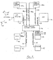
- FIG. 2 is a diagrammatic view of the image-capturing system of FIG. 1;
- FIG. 3 is a block diagram of the image-capturing computer system of Fig. 2;
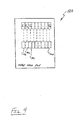
- FIG. 4 is a representation of an exemplary output data file of the image-capturing system of Fig. 1;
- FIG. 5 is a block diagram of one embodiment of an image display and measurement computer system of the present invention for displaying and taking measurements of and between objects depicted in the images captured by the image-capturing system of Fig. 1;
- FIG. 6 depicts an exemplary image displayed on the system of Fig. 5, and illustrates one embodiment of the method of the present invention for the measurement of and between objects depicted in such an image;
- FIGS. 7 and 8 illustrate one embodiment of a method for capturing oblique images of the present invention;
- FIGS. 9 and 10 illustrate a second embodiment of a method for capturing oblique images of the present invention.
- Corresponding reference characters indicate corresponding parts throughout the several views. The exemplifications set out herein illustrate one preferred embodiment of the invention, in one form, and such exemplifications are not to be construed as limiting the scope of the invention in any manner.
- Referring now to the drawings, and particularly to Fig. 1, one embodiment of an apparatus for capturing and geolocating oblique images of the present invention is shown.
Apparatus 10 includes a platform orvehicle 20 that carries image-capturing and geolocatingsystem 30. -
Platform 20, such as, for example, an airplane, space shuttle, rocket, satellite, or any other suitable vehicle, carries image-capturingsystem 30 over a predefined area of and at one or more predetermined altitudes abovesurface 31, such as, for example, the earth's surface or any other surface of interest. As such,platform 20 is capable of controlled movement or flight, either manned or unmanned, along a predefined flight path or course through, for example, the earth's atmosphere or outer space. Image-capturingplatform 20 includes a system for generating and regulating power (not shown) that includes, for example, one or more generators, fuel cells, solar panels, and/or batteries, for powering image-capturingsystem 30. - Image-capturing and geo-locating
system 30, as best shown in Fig. 2, includes image capturingdevices clock 38,gyroscope 40,compass 42 andaltimeter 44, each of which are interconnected with image-capturingcomputer system 46. - Image-capturing
devices devices devices computer system 46, as will be more particularly described hereinafter. - As best shown in Fig. 1, image-capturing
devices platform 20 such that axes A 1 and A 2 are each at an angle of declination θ relative to a horizontal plane P. Declination angle θ is virtually any oblique angle, but is preferably from approximately 20° (twenty degrees) to approximately 60° (sixty degrees) and is most preferably from approximately 40° (forty degrees) to approximately 50° (fifty degrees). - GPS receiver 34 receives global positioning system signals 52 that are transmitted by one or more global
positioning system satellites 54. The GPS signals 52, in known fashion, enable the precise location ofplatform 20 relative to surface 31 to be determined. GPS receiver 34 decodes GPS signals 52 and issues location signals/data 56, that are dependent at least in part upon GPS signals 52 and which are indicative of the precise location ofplatform 20 relative to surface 31. Location signals/data 56 corresponding to each image captured by image-capturingdevices computer system 46. -
INU 36 is a conventional inertial navigation unit that is coupled to and detects changes in the velocity, including translational and rotational velocity, of image-capturingdevices platform 20.INU 36 issues velocity signals/data 58 indicative of such velocities and/or changes therein to image-capturingcomputer system 46, which stores velocity signals/data 58 corresponding to each image captured by image-capturingdevices computer system 46. -
Clock 38 keeps a precise time measurement (time of validity) that is used to synchronize events within image-capturing and geo-locatingsystem 30.Clock 38 provides time data/clock signal 62 that is indicative of the precise time that an image is taken by image-capturingdevices Time data 62 is also provided to and stored by image-capturingcomputer system 46. Alternatively,clock 38 is integral with image-capturingcomputer system 46, such as, for example, a clock software program. -
Gyroscope 40 is a conventional gyroscope as commonly found on airplanes and/or within commercial navigation systems for airplanes.Gyroscope 40 provides signals includingpitch signal 64,roll signal 66 andyaw signal 68, which are respectively indicative of pitch, roll and yaw ofplatform 20.Pitch signal 64,roll signal 66 andyaw signal 68 corresponding to each image captured by mage-capturingdevices computer system 46. -
Compass 42, such as, for example, a conventional electronic compass, indicates the heading ofplatform 20.Compass 42 issues heading signal/data 72 that is indicative of the heading ofplatform 20. Image-capturingcomputer system 46 receives and stores the heading signals/data 72 that correspond to each image captured by image-capturingdevices -
Altimeter 44 indicates the altitude ofplatform 20.Altimeter 44 issues altitude signal/data 74, and image-capturingcomputer system 46 receives and stores the altitude signal/data 74 that correspond to each image captured by image-capturingdevices - As best shown in Fig. 3, image-capturing
computer system 46, such as, for example, a conventional laptop personal computer, includesmemory 82, input devices 84a and 84b,display device 86, and input and output (I/O)ports 88. Image-capturingcomputer system 46 executes image anddata acquiring software 90, which is stored inmemory 82.Memory 82 also stores data used and/or calculated by image-capturingcomputer system 46 during the operation thereof, and includes, for example, non-volatile read-only memory, random access memory, hard disk memory, removable memory cards and/or other suitable memory storage devices and/or media. Input devices 84a and 84b, such as, for example, a mouse, keyboard, joystick, or other such input devices, enable the input of data and interaction of a user with software being executed by image-capturingcomputer system 46.Display device 86, such as, for example, a liquid crystal display or cathode ray tube, displays information to the user of image-capturingcomputer system 46. I/O ports 88, such as, for example, serial and parallel data input and output ports, enable the input and/or output of data to and from image-capturingcomputer system 46. - Each of the above-described data signals is connected to image-capturing
computer system 46. More particularly, image data signals 48, location signals 56, velocity signals 58, time data signal 62, pitch, roll and yaw signals 64, 66 and 68, respectively, headingsignal 72 andaltitude signal 74 are received via I/O ports 88 by and stored withinmemory 82 of image-capturingcomputer system 46. - In use, image-capturing
computer system 46 executes image anddata acquiring software 90, which, in general, controls the reading, manipulation, and storing of the above-described data signals. More particularly, image anddata acquiring software 90 reads image data signals 48a and 48b and stores them withinmemory 82. Each of the location signals 56, velocity signals 58, time data signal 62, pitch, roll and yaw signals 64, 66 and 68, respectively, headingsignal 72 andaltitude signal 74 that represent the conditions existing at the instant an image is acquired or captured by image-capturingdevices computer system 46 via I/O ports 88. Image-capturingcomputer system 46 executing image anddata acquiring software 90 issues image-capture signal 92 to image-capturingdevices platform 20. - Image and
data acquiring software 90 decodes as necessary and stores the aforementioned signals withinmemory 82, and associates the data signals with the corresponding image signals 48a and 48b. Thus, the altitude, orientation in terms of roll, pitch, and yaw, and the location of image-capturingdevices devices -
Platform 20 is piloted or otherwise guided through an image-capturing path that passes over a particular area ofsurface 31, such as, for example, a predefined area of the surface of the earth or of another planet. Preferably, the image-capturing path ofplatform 20 is at right angles to at least one of the boundaries of the area of interest. I he number oftimes platform 20 and/or image-capturingdevices platform 20 are described more particularly hereinafter. - As
platform 20 passes over the area of interest a number of oblique images are captured by image-capturingdevices devices platform 20. - Image data signals 48a and 48b corresponding to each image acquired are received by and stored within
memory 82 of image-capturingcomputer system 46 via I/O ports 88. Similarly, the data signals (i.e., image data signals 48, location signals 56, velocity signals 58, time data signal 62, pitch, roll and yaw signals 64, 66 and 68, respectively, headingsignal 72 and altitude signal 74) corresponding to each captured image are received and stored withinmemory 82 of image-capturingcomputer system 46 via I/O ports 88. Thus, the location of image-capturingdevice memory 82 and associated with the corresponding captured image. - As best shown in Fig. 1, the location of image-capturing
devices orthogonal image 102. Thus, the exact geo-location of the nadir point N oforthogonal image 102 is indicated by iocation signals 56, velocity signals 58, time data signal 62, pitch, roll and yaw signals 64, 66 and 68, respectively, headingsignal 72 andaltitude signal 74. Once the nadir point N oforthogonal image 102 is known, the geo-location of any other pixel or point withinimage 102 is determinable in known manner. - When image-capturing
devices devices signal 72,altitude signal 74 and the known angle of declination θ of the primary axes A 1 and A 2 of image-capturingdevices - It should be particularly noted that a calibration process enables image and
data acquiring software 90 to incorporate correction factors and/or correct for any error inherent in or due to image-capturing device 32, such as, for example, error due to calibrated focal length, sensor size, radial distortion, principal point offset, and alignment. - Image and
data acquiring software 90 creates and stores inmemory 82 one or more output image and data files 120. More particularly, image anddata acquiring software 90 convertsimage data signals 48a, 48b and the orientation data signals (i.e., image data signals 48, location signals 56, velocity signals 58, time data signal 62, pitch, roll and yaw signals 64, 66 and 68, respectively, headingsignal 72 and altitude signal 74) into computer-readable output image and data files 120. As best shown in Fig. 4, output image and data file 120 contains a plurality of captured image files I 1 , I 2 , . .., I n corresponding to captured oblique images, and the positional data C PD1 , C PD2 , ... , C PDn corresponding thereto. - Image files I 1 , I 2 , ... , I n of the image and data file 120 are stored in virtually any computer-readable image or graphics file format, such as, for example, JPEG, TIFF, GIF, BMP, or PDF file formats, and are cross-referenced with the positional data C PD1 , C PD2 , ... , C PDn which is also stored as computer-readable data. Alternatively, positional data C PD1 , C PD2 , ..., C PDn is embedded within the corresponding image files I 1 , I 2 , ..., I n in known manner. Image data files 120 are then processed, either by image and
data acquiring software 90 or by post-processing, to correct for errors, such as, for example, errors due to flight path deviations and other errors known to one of ordinary skill in the art. Thereafter, image data files 120 are ready for use to display and make measurements of and between the objects depicted within the captured images, including measurements of the heights of such objects. - Referring now to Fig. 5, image display and
measurement computer system 130, such as, for example, a conventional desktop personal computer or a mobile computer terminal in a police car, includesmemory 132,input devices 134a and 134b,display device 136, andnetwork connection 138. Image-capturingcomputer system 130 executes image display andanalysis software 140, which is stored inmemory 132.Memory 132 includes, for example, non-volatile read-only memory, random access memory, hard disk memory, removable memory cards and/or other suitable memory storage devices and/or media.Input devices 134a and 134b, such as, for example, a mouse, keyboard, joystick, or other such input devices, enable the input of data and interaction of a user with image display andanalysis software 140 being executed by image display andmeasurement computer system 130.Display device 136, such as, for example, a liquid crystal display or cathode ray tube, displays information to the user of image display andmeasurement computer system 130.Network connection 138 connects image display andmeasurement computer system 130 to a network (not shown), such as, for example, a local-area network, wide-area network, the Internet and/or the World Wide Web. - In use, and referring now to Fig. 6, image display and
measurement computer system 130 executing image display andanalysis software 140 accesses one or more output image anddata files 120 that have been read intomemory 132, such as, for example, vianetwork connection 138, a floppy disk drive, removable memory card or other suitable means. One or more of the captured images I 1 , I 2 , ..., I n of output image and data files 120 is thereafter displayed as displayedoblique image 142 under the control of image display andanalysis software 140. At approximately the same time, one or more data portions C PD1 , C PD2 , ..., C PDn corresponding to displayedoblique image 142 are read into a readily-accessible portion ofmemory 132. - It should be particularly noted that displayed
oblique image 142 is displayed substantially as captured, i.e., displayedimage 142 is not warped or fitted to any coordinate system nor is displayedimage 142 ortho-rectified. Rather than warping displayedimage 142 to a coordinate system in order to enable measurement of objects depicted therein, image display andanalysis software 140, in general, determines the geo-locations of selected pixels only as needed, or "on the fly", by referencing data portions C PD1. C PD2 , ..., C PDn of output image anddata files 120 and calculating the position and/or geo-location of those selected pixels using one or more projection equations as is more particularly described hereinafter. - Generally, a user of display and
measurement computer system 130 takes measurements of and between objects depicted in displayedoblique image 142 by selecting one of several available measuring modes provided within image display andanalysis software 140. The user selects the desired measurement mode by accessing, for example, a series of pull-down menus or toolbars M, or via keyboard commands. The measuring modes provided by image display andanalysis software 140 include, for example, a distance mode that enables measurement of the distance between two or more selected points, an area mode that enables measurement of the area encompassed by several selected and interconnected points, a height mode that enables measurement of the height between two or more selected points, and an elevation mode that enables the measurement of the change in elevation of one selected point relative to one or more other selected points. - After selecting the desired measurement mode, the user of image display and
analysis software 140 selects with one ofinput devices 134a, 134b a starting point or startingpixel 152 and an ending point orpixel 154 on displayedimage 142, and image display andanalysis software 140 automatically calculates and displays the quantity sought, such as, for example, the distance between startingpixel 152 and endingpixel 154. - When the user selects starting point/
pixel 152, the geo-location of the point corresponding thereto onsurface 31 is calculated by image display andanalysis software 140 which executes one or more projection equations using the data portions C PD1 , C PD2 , ..., C PDn of output image anddata files 120 that correspond to the particular image being displayed. The longitude and latitude of the point onsurface 31 corresponding topixel 152 are then displayed by image display andanalysis software 140 ondisplay 136, such as, for example, by superimposing the longitude and latitude on displayedimage 142 adjacent the selected point/pixel or in pop-up display box elsewhere ondisplay 136. The same process is repeated by the user for the selection of the end pixel/point 154, and by image display andanalysis software 140 for the retrieval and display of the longitude and latitude information. - The calculation of the distance between starting and ending points/
pixels pixel surface 31 corresponding to each selected pixel are then determined. The difference between the geo-locations corresponding to the selected pixels determines the distance between the pixels. - As an example of how the geo-location of a given point or pixel within displayed
oblique image 142 is determined, we will assume that displayedimage 142 corresponds to orthogonal image 104a (Fig. 1). The user of image display andanalysis software 140 selectspixel 154 which, for simplicity, corresponds to center C (Fig. 1) of oblique image 104a. As shown in Fig. 1,line 106 extends along horizontal plane G from apoint 108 thereon that is directly below image-capturingdevice 32a to the center C of the near border or edge 108 of oblique image 104a. An extension of primary axis A 1 intersects with center C. Angle Ø is the angle formed betweenline 106 the extension of primary axis A 1 . Thus, a triangle (not referenced) is formed having vertices at image-capturingdevice 32a,point 108 and center C, and havingsides 106, the extension of primary axis A 1 and vertical (dashed)line 110 betweenpoint 108 and image-capturingdevice 32a. - Ground plane G is a substantially horizontal, flat or non-sloping ground plane (and which typically will have an elevation that reflects the average elevation of the terrain), and therefore the above-described triangle includes a right angle between side/
line 110 and side/line 106. Since angle Ø and the altitude of image-capturing device 32 (i.e., the length of side 110) are known, the hypotenuse (i.e., the length of the extension of primary axis A 1 ) and remaining other side of the right triangle are calculated by simple geometry. Further, since the exact position of image-capturingdevice 32a is known at the time the image corresponding to displayedimage 142 was captured, the latitude and longitude ofpoint 108 are also known. Knowing the length ofside 106, calculated as described above, enables the exact geo-location ofpixel 154 corresponding to center C of oblique image 104a to be determined by image display andanalysis software 140. Once the geo-location of the point corresponding topixel 154 is known, the geo-location of any other pixel in displayedoblique image 142 is determinable using the known camera characteristics, such as, for example, focal length, sensor size and aspect ratio, radial and other distortion terms, etc. - The distance between the two or more points corresponding to two or more selected pixels within displayed
image 142 is calculated by image display andanalysis software 140 by determining the difference between the geo-locations of the selected pixels using known algorithms, such as, for example, the Gauss formula and/or the vanishing point formula, dependent upon the selected measuring mode. The measurement of objects depicted or appearing in displayedimage 142 is conducted by a substantially similar procedure to the procedure described above for measuring distances between selected pixels. For example, the lengths, widths and heights of objects, such as, for example, buildings, rivers, roads, and virtually any other geographic or man-made structure, appearing within displayedimage 142 are measured by selecting the appropriate/desired measurement mode and selecting starting and ending pixels. - It should be particularly noted that in the distance measuring mode of image display and
analysis software 140 the distance between the starting and ending points/pixels - It should also be particularly noted that the distance measuring mode of image display and
analysis software 140 determines the distance between selected pixels according to a "walk the earth" method. The "walk the earth method" creates a series of interconnected line segments, represented collectively by paths P1 and P2, that extend between the selected pixels/points and which lie upon or conform to the planar faces of a series of interconnected facets that define a tessellated ground plane. The tessellated ground plane, as will be more particularly described hereinafter, closely follows or recreates the terrain ofsurface 31, and therefore paths P1 and P2 also closely follow the terrain ofsurface 31. By measuring the distance along the terrain simulated by the tessellated ground plane, the "walk the earth" method provides for a more accurate and useful measurement of the distance between selected points than the conventional approach, which warps the image onto a flat earth or average elevation plane system and measures the distance between selected points along the flat earth or plane and substantially ignores variations in terrain between the points. - For example, a contractor preparing to bid on a contract for paving a roadway over uneven or hilly terrain can determine the approximate amount or area of roadway involved using image display and
analysis software 140 and the "walk the earth" measurement method provided thereby. The contractor can obtain the approximate amount or area of roadway from his or her own office without having to send a surveying crew to the site to obtain the measurements necessary. - In contrast to the "walk the earth" method provided by the present invention, the "flat earth" or average elevation distance calculating approaches include inherent inaccuracies when measuring distances between points and/or objects disposed on uneven terrain and when measuring the sizes and/or heights of objects similarly disposed. Even a modest slope or grade in the surface being captured results in a difference in the elevation of the nadir point relative to virtually any other point of interest thereon. Thus, referring again to Fig. 1, the triangle formed by
line 106, the extension of primary axis A 1 and the vertical (dashed)line 110 betweenpoint 108 and image-capturingdevice 32a may not be a right triangle. If such is the case, any geometric calculations assuming that triangle to be a right triangle would contain errors, and such calculations would be reduced to approximations due to even a relatively slight gradient or slope between the points of interest. - For example, if
surface 31 slopes upward between nadir point N and center C at the near orbottom edge 108 of oblique image 104 thensecond line 110 intersectssurface 31 before the point at which such intersection would occur on a level ornon-sloping surface 31. If center C is fifteen feet higher than nadir point N and with a declination angle θ equal to 40° (forty degrees), the calculated location of center C would be off by approximately 17.8 feet without correction for the change in elevation between the points. - As generally discussed above, in order to compensate at least in part for changes in elevation and the resultant inaccuracies in the measurement of and between objects within
image 142, image display andanalysis software 140 references, as necessary, points within displayedimage 142 and onsurface 31 to a pre-calculated tessellated or faceted ground plane generally designated 160 in Fig. 6.Tessellated ground plane 160 includes a plurality of individual facets 162a, 162b, 162c, etc., each of which are interconnected to each other and are defined by four vertices (not referenced, but shown as points) having respective elevations. Adjacent pairs of facets 162a, 162b, 162c, etc., share two vertices. Each facet 162a, 162b, 162c, etc., has a respective pitch and slope.Tessellated ground plane 160 is created based upon various data and resources, such as, for example, topographical maps, and/or digital raster graphics, survey data, and various other sources. - Generally, the geo-location of a point of interest on displayed
image 142 is calculated by determining which of facets 162a, 162b, 162c, etc., correspond to that point of interest. Thus, the location of the point of interest is calculated based on the characteristics, i.e., elevation, pitch and slope, of facets 162a, 162b, 162c, etc., rather than based upon a flat or average-elevation ground plane. Error is introduced only in so far as the topography ofsurface 31 and the location of the point of interest thereon deviate from the planar surface of the facet 162a, 162b, 162c, etc, within which the point of interest lies. That error is reducible through a bilinear interpolation of the elevation of the point of interest within a particular one of facets 162a, 162b, 162c, etc., and using that interpolated elevation in the location calculation performed by image display andanalysis software 140. - To use
tessellated ground plane 160, image display andanalysis software 140 employs a modified ray-tracing algorithm to find the intersection of the ray projected from the image-capturingdevice surface 31 andtessellated ground plane 160. The algorithm determines not only which of facets 162a, 162b, 162c, etc., is intersected by the ray, but also where within the facet the intersection occurs. By use of bi-linear interpolation, a fairly precise ground location can be determined. For the reverse projection, tessellatedground plane 160 is used to find the ground elevation value for the input ground location also using bi-linear interpolation. The elevation and location are then used to project backwards through a model of the image-capturingdevice image 142 corresponds to the given location. - More particularly, and as an example, image display and
analysis software 140 performs and/or calculates the geo-location ofpoint 164 by superimposing and/or fittingtessellated ground plane 160 to at least a portion 166, such as, for example, a hill, ofsurface 31. It should be noted that only a small portion oftessellated ground plane 160 and facets 162a, 162b, 162c, etc., thereof is shown along the profile of portion 166 ofsurface 31. As discussed above, each of facets 162a, 162b, 162c, etc., are defined by four vertices, each of which have respective elevations, and each of the facets have respective pitches and slopes. The specific position ofpoint 164 upon the plane/surface of the facet 162a, 162b, 162c, etc., within which point 164 (or its projection) lies is determined as described above. -
Tessellated ground plane 160 is preferably created outside the operation of image display andmeasurement computer system 130 and image display andanalysis software 140. Rather, tessellatedground plane 160 takes the form of a relatively simple data table or look-up table 168 stored withinmemory 132 of and/or accessible to image display andmeasurement computer system 130. The computing resources required to calculate the locations of all the vertices of the many facets of a typical ground plane do not necessarily have to reside within image display andmeasurement computer system 130. Thus, image display andmeasurement computer system 130 is compatible for use with and executable by a conventional personal computer without requiring additional computing resources. - Calculating
tessellated ground plane 160 outside of image display andmeasurement computer system 130 enables virtually any level of detail to be incorporated into tessellatedground plane 160, i.e., the size and/or area covered by or corresponding to each of facets 162a, 162b, 162c, etc., can be as large or as small as desired, without significantly increasing the calculation time, slowing the operation of, nor significantly increasing the resources required by image display andmeasurement computer system 130 and/or image display andanalysis software 140. Display andmeasurement computer system 130 can therefore be a relatively basic and uncomplicated computer system. - The size of facets 162a, 162b, 162c, etc., are uniform in size throughout a particular displayed
image 142. For example, if displayedimage 142 corresponds to an area that is approximately 750 feet wide in the foreground by approximately 900 feet deep, the image can be broken into facets that are approximately 50 square feet, thus yielding about 15 facets in width and 18 facets in depth. Alternatively, the size of facets 162a, 162b, 162c, etc., are uniform in terms of the number of pixels contained therein, i.e., each facet is the same number of pixels wide and the same number of pixels deep. Facets in the foreground of displayedimage 142, where the pixel density is greatest, would therefore be dimensionally smaller than facets in the background of displayedimage 142 where pixel density is lowest. Since it is desirable to take most measurements in the foreground of a displayed image where pixel density is greatest, creating facets that are uniform in terms of the number of pixels they contain has the advantage of providing more accurate measurements in the foreground of displayedimage 142 relative to facets that are dimensionally uniform. - Another advantage of using pixels as a basis for defining the dimensions of facets 162a, 162b, 162c, etc., is that the location calculation (pixel location to ground location) is relatively simple. A user operates image display and
measurement computer system 130 to select a pixel within a given facet, image display andanalysis software 140 looks up the data for the facet corresponding to the selected pixel, the elevation of the selected pixel is calculated as discussed above, and that elevation is used within the location calculation. - Generally, the method of capturing oblique images of the present invention divides an area of interest, such as, for example, a county, into sectors of generally uniform size, such as, for example, sectors that are approximately one square mile in area. This is done to facilitate the creation of a flight plan to capture oblique images covering every inch of the area of interest, and to organize and name the sectors and/or images thereof for easy reference, storage and retrieval (a process known in the art as "sectorization"). Because the edges of any geographic area of interest, such as a county, rarely falls on even square mile boundaries, the method of capturing oblique images of the present invention provides more sectors than there are square miles in the area of interest ― how many more depends largely on the length of the county borders as well as how straight or jagged they are. Typically, you can expect one extra sector for every two to three miles of border. So if a county or other area of interest is roughly 20 miles by 35 miles, or 700 square miles, the area will be divided into approximately from 740 to 780 sectors.
- The method of capturing oblique images of the present invention, in general, captures the oblique images from at least two compass directions, and provides full coverage of the area of interest from at least those two compass directions. Referring now to Figs. 7 and 8, a first embodiment of a method for capturing oblique images of the present invention is shown. For sake of clarity, Fig. 7 and 8 is based on a system having only one image-capturing device. However, it is to be understood that two or more image-capturing devices can be used.
- The image-capturing device captures one or more oblique images during each pass over
area 200. The image-capturing device, as discussed above, is aimed at an angle overarea 200 to capture oblique images thereof.Area 200 is traversed in a back-and-forth pattern, similar to the way a lawn is mowed, by the image-carrying device and/or the platform to ensure double coverage ofarea 200. - More particularly,
area 200 is traversed by image-carrying device 32 and/orplatform 20 following afirst path 202 to thereby capture oblique images ofportions 202a, 202b, and 202c ofarea 200.Area 200 is then traversed by image-carrying device 32 and/orplatform 20 following asecond path 204 that is parallel and spaced apart from, and in an opposite direction to, i.e., 180° (one-hundred and eighty degrees) from,first path 202, to thereby capture oblique images ofportions area 200. By comparing Figs. 7 and 8, it is seen that a portion 207 (Fig. 8) ofarea 200 is covered by images 202a-c captured from a first direction or perspective, and byimages 204a-c captured from a second direction or perspective. As such, the middle portion ofarea 200 is 100% (one-hundred percent) double covered. The above-described pattern of traversing or passing overarea 200 along opposing paths that are parallel topaths area 200 is completely covered by at least one oblique image captured from paths that are parallel to, spaced apart from each other as dictated by the size ofarea 200, and in the same direction aspaths double cover area 200 from those perspectives/directions. - If desired, and for enhanced detail,
area 200 is covered by two additional opposing and parallel third andfourth paths paths Area 200 is therefore traversed by image-carrying device 32 and/orplatform 20 followingthird path 206 to capture oblique images of portions 206a, 206b and 206c ofarea 200, and is then traversed alongfourth path 208 that is parallel, spaced apart from, and opposite tothird path 206 to capture oblique images ofportions 208a, 208b and 208c ofarea 200. This pattern of traversing or passing overarea 200 along opposing paths that are parallel topaths area 200 is completely covered by at least one oblique image captured from paths that are parallel to, spaced apart from as dictated by the size ofarea 200, and in the same direction aspaths double cover area 200 from those directions/perspectives. - As described above, image-carrying device 32 and/or
platform 20, traverses or passes overarea 200 along a predetermined path. However, it is to be understood that image-carrying device and/orplatform 20 do not necessarily pass or traverse directly overarea 200 but rather may pass or traverse an area adjacent, proximate to, or even somewhat removed from,area 200 in order to ensure that the portion ofarea 200 that is being imaged falls within the image-capture field of the image-capturing device.Path 202, as shown in Fig. 7, is such a path that does not pass directly overarea 200 but yet captures oblique images thereof. - The present invention is capable of capturing images at various levels of resolution or ground sample distances. A first level of detail, hereinafter referred to as a community level, has a ground sample distance of, for example, approximately two-feet per pixel. For orthogonal community-level images, the ground sample distance remains substantially constant throughout the image. Orthogonal community-level images are captured with sufficient overlap to provide stereo pair coverage. For oblique community-level images, the ground sample distance varies from, for example, approximately one-foot per pixel in the foreground of the image to approximately two-feet per pixel in the mid-ground of the image, and to approximately four-feet per pixel in the background of the image. Oblique community-level images are captured with sufficient overlap such that each area of interest is typically covered by at least two oblique images from each compass direction captured. Approximately ten oblique community-level images are captured per sector.
- A second level of detail, hereinafter referred to as a neighborhood level, is significantly more detailed than the community-level images. Neighborhood-level images have a ground sample distance of, for example, approximately six-inches per pixel. For orthogonal neighborhood-level images, the ground sample distance remains substantially constant. Oblique neighborhood-level images have a ground sample distance of, for example, from approximately four-inches per pixel in the foreground of the image to approximately six-inches per pixel in the mid-ground of the image, and to approximately ten-inches per pixel in the background of the image. Oblique neighborhood-level images are captured with sufficient overlap such that each area of interest is typically covered by at least two oblique images from each compass direction captured, and such that opposing compass directions provide 100% overlap with each other. Approximately one hundred (100) oblique area images are captured per sector.
- It should be particularly noted that capturing oblique community and/or neighborhood-level images from all four compass directions ensures that every point in the image will appear in the foreground or lower portion of at least one of the captured oblique images, where ground sample distance is lowest and image detail is greatest.
- In the embodiment shown, image-capturing and geo-locating
system 30 includes a gyroscope, compass and altimeter. However, it is to be understood that the image-capturing and geo-locating system of the present invention can be alternately configured, such as, for example, to derive and/or calculate altitude, pitch, roll and yaw, and compass heading from the GPS and INU signals/data, thereby rendering one or more of the gyroscope, compass and altimeter unnecessary. In fact, - In the embodiment shown, image-capturing devices are at an equal angle of declination relative to a horizontal plane. However, it is to be understood that the declination angles of the image-capturing devices do not have to be equal.
- In the embodiment shown, image-capturing computer system executes image and data acquiring software that issues a common or single image-capture signal to the image-capturing devices to thereby cause those devices to acquire or capture an image. However, it is to be understood that the present invention can be alternately configured to separately cause the image-capturing devices to capture images at different instants and/or at different intervals.
- In the embodiment shown, the method of the present invention captures oblique images to provide double coverage of an area of interest from paths/perspectives that are substantially opposite to each other, i.e., 180° (one-hundred and eighty degrees) relative to each other. However, it is to be understood that the method of the present invention can be alternately configured to provide double coverage from paths/perspectives that are generally and/or substantially perpendicular relative to each other.
- While the present invention has been described as having a preferred design, the invention can be further modified within the spirit and scope of this disclosure. This disclosure is therefore intended to encompass any equivalents to the structures and elements disclosed herein. Further, this disclosure is intended to encompass any variations, uses, or adaptations of the present invention that use the general principles disclosed herein. Moreover, this disclosure is intended to encompass any departures from the subject matter disclosed that come within the known or customary practice in the pertinent art and which fall within the limits of the appended claims.
Claims (27)
- A method of capturing oblique images of an area of interest with an image-capturing device carried by a platform, each oblique image captured at a respective image-capturing event, said method comprising:subdividing the area of interest into a plurality of sectors;guiding the platform along a first path to thereby target one or more target sectors with the image-capturing device;capturing with the image-capturing device one or more oblique images to thereby cover an entirety of each said target sector in oblique images captured from a first perspective; guiding the platform along a second path to thereby target said target sectors;capturing with the image-capturing device one or more oblique images to thereby cover an entirety of each said target sector in oblique images captured from a second perspective; repeating said guiding and capturing steps along paths substantially parallel to and spaced apart from said first and second paths and capturing one or more oblique images to thereby cover an entirety of each of said plurality of sectors in oblique images captured from each of said first and second perspectives; andrecording positional data indicative of a geo-location of said image-capturing device at each image-capturing event.
- The method of claim 1, wherein said second path is substantially parallel relative to and 180° from said first path.
- The method of claim 1, wherein said second path is also spaced apart from said first path.
- The method of claim 1, comprising the further steps of:guiding the platform along a third path to thereby target one or more target sectors with the image-capturing device, said third path being substantially perpendicular to said first and second paths;capturing with the image-capturing device one or more oblique images to thereby capture an entirety of each said target sector in oblique images captured from a third perspective; andrepeating said guiding and capturing steps along paths substantially parallel to and spaced apart from said third path and capturing one or more oblique images to thereby cover an entirety of each of said plurality of sectors in oblique images captured from said third perspective.
- The method of claim 4, comprising the further steps of:guiding the platform along a fourth path to thereby target one or more target sectors with the image-capturing device, said fourth path being substantially parallel with said third path and 180° from said third path;capturing with the image-capturing device one or more oblique images to thereby capture an entirety of each said target sector in oblique images captured from a fourth perspective; andrepeating said guiding and capturing steps along paths substantially parallel to and spaced apart from said fourth path and capturing one or more oblique images to thereby cover an entirety of each of said plurality of sectors in oblique images captured from said fourth perspective.
- The method of claim 5, wherein said fourth path is also spaced apart from said third path.
- A computerized method for taking measurements from an oblique image displayed on a computer system, at least one input device connected to said computer system, an image data file accessible by said computer system, said image data file including captured images and positional data corresponding thereto, said computerized method comprising:placing the computer system into a desired one of a plurality of measurement modes, the desired measurement mode configured for calculating a desired measurement;selecting a starting point on the displayed image;retrieving the positional data corresponding to said starting point;selecting an end point on the displayed image;retrieving the positional data corresponding to said end point; andcalculating the desired measurement dependent at least in part upon said positional data of said starting and end points.
- The method of claim 7, comprising the further steps of:selecting one or more intermediate points on said displayed image; andretrieving the positional data corresponding to said intermediate points.
- The method of claim 7, wherein said plurality of measurement modes comprise a distance measuring mode calculating a distance between two or more selected points, a height measuring mode calculating a height difference between two or more selected points, a relative elevation measurement mode calculating the difference in elevation of two or more selected points, and an area measurement mode calculating the area encompassed by at least three points.
- A computerized method for taking measurements within a displayed oblique image, comprising:selecting with an input device a starting point and an end point on the displayed image; retrieving from a data file positional data corresponding to said starting point and said end point;referencing a ground plane data file corresponding to a tessellated ground plane having a plurality of facets, each of said facets having a respective pitch and slope, said tessellated ground plane closely matching a terrain of said displayed oblique image;connecting said starting and end points with line segments, said line segments conforming to said pitch and slope of said facets to thereby follow said terrain; andcalculating the linear distance along said line segments between said starting and end points thereby taking into account said pitch and slope of said facets.
- The method of claim 10, wherein said tessellated ground plane is superimposed upon said displayed oblique image.
- The method of claim 10, comprising the further steps of:selecting with an input device one or more intermediate points on the displayed image; retrieving from said data file positional data corresponding to said one or more intermediate points; andconnecting adjacent intermediate points to each other, and connecting said starting and end points to adjacent intermediate points, with line segments, said line segments conforming to said pitch and slope of said facets to thereby follow said terrain; andcalculating the distance along said line segments between said starting and end points.
- The method of claim 10, wherein said plurality of facets each correspond to equal areas of said displayed oblique image.
- The method of claim 10, wherein said plurality of facets each includes an equal number of pixels of said displayed oblique image.
- A computerized method for taking measurements within a displayed oblique image, comprising:displaying an oblique captured image with positional data;selecting with an input device two points including a starting point and an end point on the displayed image;calculating the geo-locations of the selected points in the displayed oblique image based at least in part the upon positional data of the displayed oblique image;referencing a tessellated ground plane representing at least a portion of the terrain depicted within said captured oblique images, said tessellated ground plane comprising a plurality of interconnected facets, each of said facets having a respective pitch and slope, said tessellated ground plane comprising a plurality of vertices, each vertex having an elevation and defining a corner of a facet, two of said vertices shared by each of said facets;identifying which of said plurality of facets corresponds to selected points on said displayed oblique image and calculating elevations of said selected points dependent at least in part upon the elevation of the vertices of the facet corresponding to the selected point; andcalculating the distance between the selected points.
- The method of claim 15 comprising the further step of superimposing an image of the upon said displayed oblique image.
- The method of claim 15, comprising the further steps of:selecting with an input device one or more intermediate points on the displayed image; retrieving from said data file positional data corresponding to said one or more intermediate points;connecting adjacent intermediate points to each other;connecting said starting and end points to adjacent intermediate points, with line segments, said line segments conforming to said pitch and slope of said facets to thereby follow said terrain; andcalculating the distance along said line segments between said starting and end points.
- The method of claim 15, wherein said plurality of facets each correspond to equal areas of said displayed oblique image.
- The method of claim 15, wherein said plurality of facets each includes an equal number of pixels of said displayed oblique image.
- The method of claim 15, comprising the further steps of:selecting one or more intermediate points on said displayed image; and retrieving the positional data corresponding to said intermediate points.
- The method of claim 15 wherein the step of calculating distance comprises measuring the different in elevation between two selected points or measuring area defined by at least three points.
- The method of claim 15 comprising the further steps of capturing oblique images of an area of interest with an image-capturing device carried by a platform, each oblique image captured at a respective image-capturing event, said method comprising:subdividing the area of interest into a plurality of sectors;guiding the platform along a first path to thereby target one or more target sectors with the image-capturing device;capturing with the image-capturing device one or more oblique images to thereby cover an entirety of each said target sector in oblique images captured from a first perspective;guiding the platform along a second path to thereby target said target sectors; capturing with the image-capturing device one or more oblique images to thereby cover an entirety of each said target sector in oblique images captured from a second perspective;repeating said guiding and capturing steps along paths substantially parallel to and spaced apart from said first and second paths and capturing one or more oblique images to thereby cover an entirety of each of said plurality of sectors in oblique images captured from each of said first and second perspectives; andrecording positional data indicative of a geo-location of said image-capturing device at each image-capturing event.
- The method of claim 22, wherein said second path is substantially parallel relative to and 180° from said first path;
- The method of claim 23, wherein said second path is also spaced apart from said first path.
- The method of claim 22, comprising the further steps of: guiding the platform along a third path to thereby target one or more target sectors with the image-capturing device, said third path being substantially perpendicular to said first and second paths;capturing with the image-capturing device one or more oblique images to thereby capture an entirety of each said target sector in oblique images captured from a third perspective; andrepeating said guiding and capturing steps along paths substantially parallel to and spaced apart from said third path and capturing one or more oblique images to thereby cover an entirety of each of said plurality of sectors in oblique images captured from said third perspective.
- The method of claim 25, comprising the further steps of:guiding the platform along a fourth path to thereby target one or more target sectors with the image-capturing device, said fourth path being substantially parallel with said third path and 180° from said third path;capturing with the image-capturing device one or more oblique images to thereby capture an entirety of each said target sector in oblique images captured from a fourth perspective; andrepeating said guiding and capturing steps along paths substantially parallel to and spaced apart from said fourth path and capturing one or more oblique images to thereby cover an entirety of each of said plurality of sectors in oblique images captured from said fourth perspective.
- The method of claim 26, wherein said fourth path is also spaced apart from said third path.
Priority Applications (1)
| Application Number | Priority Date | Filing Date | Title |
|---|---|---|---|
| EP10011757.1A EP2261600B1 (en) | 2002-11-08 | 2003-11-07 | Method and apparatus for capturing, geolocating and measuring oblique images |
Applications Claiming Priority (2)
| Application Number | Priority Date | Filing Date | Title |
|---|---|---|---|
| US42527502P | 2002-11-08 | 2002-11-08 | |
| EP03025702A EP1418402B1 (en) | 2002-11-08 | 2003-11-07 | Method and apparatus for capturing, geolocating and measuring oblique images |
Related Parent Applications (2)
| Application Number | Title | Priority Date | Filing Date |
|---|---|---|---|
| EP03025702.6 Division | 2003-11-07 | ||
| EP03025702A Division EP1418402B1 (en) | 2002-11-08 | 2003-11-07 | Method and apparatus for capturing, geolocating and measuring oblique images |
Related Child Applications (3)
| Application Number | Title | Priority Date | Filing Date |
|---|---|---|---|
| EP10011757.1A Division EP2261600B1 (en) | 2002-11-08 | 2003-11-07 | Method and apparatus for capturing, geolocating and measuring oblique images |
| EP10011757.1A Division-Into EP2261600B1 (en) | 2002-11-08 | 2003-11-07 | Method and apparatus for capturing, geolocating and measuring oblique images |
| EP10011757.1 Division-Into | 2010-09-29 |
Publications (3)
| Publication Number | Publication Date |
|---|---|
| EP1696204A2 true EP1696204A2 (en) | 2006-08-30 |
| EP1696204A3 EP1696204A3 (en) | 2011-01-26 |
| EP1696204B1 EP1696204B1 (en) | 2015-01-28 |
Family
ID=36693564
Family Applications (1)
| Application Number | Title | Priority Date | Filing Date |
|---|---|---|---|
| EP06012675.2A Expired - Lifetime EP1696204B1 (en) | 2002-11-08 | 2003-11-07 | Method for capturing, geolocating and measuring oblique images |
Country Status (1)
| Country | Link |
|---|---|
| EP (1) | EP1696204B1 (en) |
Cited By (27)
| Publication number | Priority date | Publication date | Assignee | Title |
|---|---|---|---|---|
| EP1965272A2 (en) | 2007-02-28 | 2008-09-03 | Brother Kogyo Kabushiki Kaisha | Cartridge comprising an engagement gear and a rotation body |
| US7787659B2 (en) | 2002-11-08 | 2010-08-31 | Pictometry International Corp. | Method and apparatus for capturing, geolocating and measuring oblique images |
| US7873238B2 (en) | 2006-08-30 | 2011-01-18 | Pictometry International Corporation | Mosaic oblique images and methods of making and using same |
| US7991226B2 (en) | 2007-10-12 | 2011-08-02 | Pictometry International Corporation | System and process for color-balancing a series of oblique images |
| US8385672B2 (en) | 2007-05-01 | 2013-02-26 | Pictometry International Corp. | System for detecting image abnormalities |
| US8401222B2 (en) | 2009-05-22 | 2013-03-19 | Pictometry International Corp. | System and process for roof measurement using aerial imagery |
| US8477190B2 (en) | 2010-07-07 | 2013-07-02 | Pictometry International Corp. | Real-time moving platform management system |
| US8497905B2 (en) | 2008-04-11 | 2013-07-30 | nearmap australia pty ltd. | Systems and methods of capturing large area images in detail including cascaded cameras and/or calibration features |
| US8520079B2 (en) | 2007-02-15 | 2013-08-27 | Pictometry International Corp. | Event multiplexer for managing the capture of images |
| US8531472B2 (en) | 2007-12-03 | 2013-09-10 | Pictometry International Corp. | Systems and methods for rapid three-dimensional modeling with real façade texture |
| US8588547B2 (en) | 2008-08-05 | 2013-11-19 | Pictometry International Corp. | Cut-line steering methods for forming a mosaic image of a geographical area |
| US8593518B2 (en) | 2007-02-01 | 2013-11-26 | Pictometry International Corp. | Computer system for continuous oblique panning |
| US8675068B2 (en) | 2008-04-11 | 2014-03-18 | Nearmap Australia Pty Ltd | Systems and methods of capturing large area images in detail including cascaded cameras and/or calibration features |
| US8823732B2 (en) | 2010-12-17 | 2014-09-02 | Pictometry International Corp. | Systems and methods for processing images with edge detection and snap-to feature |
| US9612598B2 (en) | 2014-01-10 | 2017-04-04 | Pictometry International Corp. | Unmanned aircraft structure evaluation system and method |
| US9633425B2 (en) | 2007-05-01 | 2017-04-25 | Pictometry International Corp. | System for detecting image abnormalities |
| US9753950B2 (en) | 2013-03-15 | 2017-09-05 | Pictometry International Corp. | Virtual property reporting for automatic structure detection |
| US9805059B2 (en) | 2013-03-15 | 2017-10-31 | Pictometry International Corp. | System and method for early access to captured images |
| US9881163B2 (en) | 2013-03-12 | 2018-01-30 | Pictometry International Corp. | System and method for performing sensitive geo-spatial processing in non-sensitive operator environments |
| US9953112B2 (en) | 2014-02-08 | 2018-04-24 | Pictometry International Corp. | Method and system for displaying room interiors on a floor plan |
| US9959667B2 (en) | 2009-10-26 | 2018-05-01 | Pictometry International Corp. | Method for the automatic material classification and texture simulation for 3D models |
| US10325350B2 (en) | 2011-06-10 | 2019-06-18 | Pictometry International Corp. | System and method for forming a video stream containing GIS data in real-time |
| US10338222B2 (en) | 2014-01-31 | 2019-07-02 | Pictometry International Corp. | Augmented three dimensional point collection of vertical structures |
| US10346935B2 (en) | 2012-03-19 | 2019-07-09 | Pictometry International Corp. | Medium and method for quick square roof reporting |
| US10402676B2 (en) | 2016-02-15 | 2019-09-03 | Pictometry International Corp. | Automated system and methodology for feature extraction |
| US10502813B2 (en) | 2013-03-12 | 2019-12-10 | Pictometry International Corp. | LiDAR system producing multiple scan paths and method of making and using same |
| US10671648B2 (en) | 2016-02-22 | 2020-06-02 | Eagle View Technologies, Inc. | Integrated centralized property database systems and methods |
Family Cites Families (2)
| Publication number | Priority date | Publication date | Assignee | Title |
|---|---|---|---|---|
| US3153784A (en) * | 1959-12-24 | 1964-10-20 | Us Industries Inc | Photo radar ground contour mapping system |
| AU9783798A (en) * | 1997-10-06 | 1999-04-27 | John A. Ciampa | Digital-image mapping |
-
2003
- 2003-11-07 EP EP06012675.2A patent/EP1696204B1/en not_active Expired - Lifetime
Non-Patent Citations (1)
| Title |
|---|
| None |
Cited By (78)
| Publication number | Priority date | Publication date | Assignee | Title |
|---|---|---|---|---|
| US10607357B2 (en) | 2002-11-08 | 2020-03-31 | Pictometry International Corp. | Method and apparatus for capturing, geolocating and measuring oblique images |
| US7787659B2 (en) | 2002-11-08 | 2010-08-31 | Pictometry International Corp. | Method and apparatus for capturing, geolocating and measuring oblique images |
| US9811922B2 (en) | 2002-11-08 | 2017-11-07 | Pictometry International Corp. | Method and apparatus for capturing, geolocating and measuring oblique images |
| US11069077B2 (en) | 2002-11-08 | 2021-07-20 | Pictometry International Corp. | Method and apparatus for capturing, geolocating and measuring oblique images |
| US7995799B2 (en) * | 2002-11-08 | 2011-08-09 | Pictometry International Corporation | Method and apparatus for capturing geolocating and measuring oblique images |
| US10489953B2 (en) | 2006-08-30 | 2019-11-26 | Pictometry International Corp. | Mosaic oblique images and methods of making and using same |
| US11080911B2 (en) | 2006-08-30 | 2021-08-03 | Pictometry International Corp. | Mosaic oblique images and systems and methods of making and using same |
| US9959653B2 (en) | 2006-08-30 | 2018-05-01 | Pictometry International Corporation | Mosaic oblique images and methods of making and using same |
| US7873238B2 (en) | 2006-08-30 | 2011-01-18 | Pictometry International Corporation | Mosaic oblique images and methods of making and using same |
| US9805489B2 (en) | 2006-08-30 | 2017-10-31 | Pictometry International Corp. | Mosaic oblique images and methods of making and using same |
| US8593518B2 (en) | 2007-02-01 | 2013-11-26 | Pictometry International Corp. | Computer system for continuous oblique panning |
| US8520079B2 (en) | 2007-02-15 | 2013-08-27 | Pictometry International Corp. | Event multiplexer for managing the capture of images |
| EP1965272A2 (en) | 2007-02-28 | 2008-09-03 | Brother Kogyo Kabushiki Kaisha | Cartridge comprising an engagement gear and a rotation body |
| US9633425B2 (en) | 2007-05-01 | 2017-04-25 | Pictometry International Corp. | System for detecting image abnormalities |
| US9959609B2 (en) | 2007-05-01 | 2018-05-01 | Pictometry International Corporation | System for detecting image abnormalities |
| US10198803B2 (en) | 2007-05-01 | 2019-02-05 | Pictometry International Corp. | System for detecting image abnormalities |
| US11100625B2 (en) | 2007-05-01 | 2021-08-24 | Pictometry International Corp. | System for detecting image abnormalities |
| US11514564B2 (en) | 2007-05-01 | 2022-11-29 | Pictometry International Corp. | System for detecting image abnormalities |
| US10679331B2 (en) | 2007-05-01 | 2020-06-09 | Pictometry International Corp. | System for detecting image abnormalities |
| US8385672B2 (en) | 2007-05-01 | 2013-02-26 | Pictometry International Corp. | System for detecting image abnormalities |
| US7991226B2 (en) | 2007-10-12 | 2011-08-02 | Pictometry International Corporation | System and process for color-balancing a series of oblique images |
| US11087506B2 (en) | 2007-10-12 | 2021-08-10 | Pictometry International Corp. | System and process for color-balancing a series of oblique images |
| US10580169B2 (en) | 2007-10-12 | 2020-03-03 | Pictometry International Corp. | System and process for color-balancing a series of oblique images |
| US8531472B2 (en) | 2007-12-03 | 2013-09-10 | Pictometry International Corp. | Systems and methods for rapid three-dimensional modeling with real façade texture |
| US9836882B2 (en) | 2007-12-03 | 2017-12-05 | Pictometry International Corp. | Systems and methods for rapid three-dimensional modeling with real facade texture |
| US11263808B2 (en) | 2007-12-03 | 2022-03-01 | Pictometry International Corp. | Systems and methods for rapid three-dimensional modeling with real façade texture |
| US10573069B2 (en) | 2007-12-03 | 2020-02-25 | Pictometry International Corp. | Systems and methods for rapid three-dimensional modeling with real facade texture |
| US10896540B2 (en) | 2007-12-03 | 2021-01-19 | Pictometry International Corp. | Systems and methods for rapid three-dimensional modeling with real façade texture |
| US10229532B2 (en) | 2007-12-03 | 2019-03-12 | Pictometry International Corporation | Systems and methods for rapid three-dimensional modeling with real facade texture |
| US9972126B2 (en) | 2007-12-03 | 2018-05-15 | Pictometry International Corp. | Systems and methods for rapid three-dimensional modeling with real facade texture |
| US10358234B2 (en) | 2008-04-11 | 2019-07-23 | Nearmap Australia Pty Ltd | Systems and methods of capturing large area images in detail including cascaded cameras and/or calibration features |
| US8497905B2 (en) | 2008-04-11 | 2013-07-30 | nearmap australia pty ltd. | Systems and methods of capturing large area images in detail including cascaded cameras and/or calibration features |
| US10358235B2 (en) | 2008-04-11 | 2019-07-23 | Nearmap Australia Pty Ltd | Method and system for creating a photomap using a dual-resolution camera system |
| US8675068B2 (en) | 2008-04-11 | 2014-03-18 | Nearmap Australia Pty Ltd | Systems and methods of capturing large area images in detail including cascaded cameras and/or calibration features |
| US9898802B2 (en) | 2008-08-05 | 2018-02-20 | Pictometry International Corp. | Cut line steering methods for forming a mosaic image of a geographical area |
| US8588547B2 (en) | 2008-08-05 | 2013-11-19 | Pictometry International Corp. | Cut-line steering methods for forming a mosaic image of a geographical area |
| US10839484B2 (en) | 2008-08-05 | 2020-11-17 | Pictometry International Corp. | Cut-line steering methods for forming a mosaic image of a geographical area |
| US10424047B2 (en) | 2008-08-05 | 2019-09-24 | Pictometry International Corp. | Cut line steering methods for forming a mosaic image of a geographical area |
| US11551331B2 (en) | 2008-08-05 | 2023-01-10 | Pictometry International Corp. | Cut-line steering methods for forming a mosaic image of a geographical area |
| US9933254B2 (en) | 2009-05-22 | 2018-04-03 | Pictometry International Corp. | System and process for roof measurement using aerial imagery |
| US8401222B2 (en) | 2009-05-22 | 2013-03-19 | Pictometry International Corp. | System and process for roof measurement using aerial imagery |
| US10198857B2 (en) | 2009-10-26 | 2019-02-05 | Pictometry International Corp. | Method for the automatic material classification and texture simulation for 3D models |
| US9959667B2 (en) | 2009-10-26 | 2018-05-01 | Pictometry International Corp. | Method for the automatic material classification and texture simulation for 3D models |
| US11483518B2 (en) | 2010-07-07 | 2022-10-25 | Pictometry International Corp. | Real-time moving platform management system |
| US8477190B2 (en) | 2010-07-07 | 2013-07-02 | Pictometry International Corp. | Real-time moving platform management system |
| US10621463B2 (en) | 2010-12-17 | 2020-04-14 | Pictometry International Corp. | Systems and methods for processing images with edge detection and snap-to feature |
| US8823732B2 (en) | 2010-12-17 | 2014-09-02 | Pictometry International Corp. | Systems and methods for processing images with edge detection and snap-to feature |
| US11003943B2 (en) | 2010-12-17 | 2021-05-11 | Pictometry International Corp. | Systems and methods for processing images with edge detection and snap-to feature |
| US10325350B2 (en) | 2011-06-10 | 2019-06-18 | Pictometry International Corp. | System and method for forming a video stream containing GIS data in real-time |
| US10346935B2 (en) | 2012-03-19 | 2019-07-09 | Pictometry International Corp. | Medium and method for quick square roof reporting |
| US10311238B2 (en) | 2013-03-12 | 2019-06-04 | Pictometry International Corp. | System and method for performing sensitive geo-spatial processing in non-sensitive operator environments |
| US10502813B2 (en) | 2013-03-12 | 2019-12-10 | Pictometry International Corp. | LiDAR system producing multiple scan paths and method of making and using same |
| US11525897B2 (en) | 2013-03-12 | 2022-12-13 | Pictometry International Corp. | LiDAR system producing multiple scan paths and method of making and using same |
| US9881163B2 (en) | 2013-03-12 | 2018-01-30 | Pictometry International Corp. | System and method for performing sensitive geo-spatial processing in non-sensitive operator environments |
| US10311089B2 (en) | 2013-03-15 | 2019-06-04 | Pictometry International Corp. | System and method for early access to captured images |
| US9753950B2 (en) | 2013-03-15 | 2017-09-05 | Pictometry International Corp. | Virtual property reporting for automatic structure detection |
| US9805059B2 (en) | 2013-03-15 | 2017-10-31 | Pictometry International Corp. | System and method for early access to captured images |
| US10037463B2 (en) | 2014-01-10 | 2018-07-31 | Pictometry International Corp. | Unmanned aircraft structure evaluation system and method |
| US11120262B2 (en) | 2014-01-10 | 2021-09-14 | Pictometry International Corp. | Unmanned aircraft structure evaluation system and method |
| US10204269B2 (en) | 2014-01-10 | 2019-02-12 | Pictometry International Corp. | Unmanned aircraft obstacle avoidance |
| US10181081B2 (en) | 2014-01-10 | 2019-01-15 | Pictometry International Corp. | Unmanned aircraft structure evaluation system and method |
| US11747486B2 (en) | 2014-01-10 | 2023-09-05 | Pictometry International Corp. | Unmanned aircraft structure evaluation system and method |
| US10181080B2 (en) | 2014-01-10 | 2019-01-15 | Pictometry International Corp. | Unmanned aircraft structure evaluation system and method |
| US9612598B2 (en) | 2014-01-10 | 2017-04-04 | Pictometry International Corp. | Unmanned aircraft structure evaluation system and method |
| US10037464B2 (en) | 2014-01-10 | 2018-07-31 | Pictometry International Corp. | Unmanned aircraft structure evaluation system and method |
| US10032078B2 (en) | 2014-01-10 | 2018-07-24 | Pictometry International Corp. | Unmanned aircraft structure evaluation system and method |
| US11087131B2 (en) | 2014-01-10 | 2021-08-10 | Pictometry International Corp. | Unmanned aircraft structure evaluation system and method |
| US10318809B2 (en) | 2014-01-10 | 2019-06-11 | Pictometry International Corp. | Unmanned aircraft structure evaluation system and method |
| US10338222B2 (en) | 2014-01-31 | 2019-07-02 | Pictometry International Corp. | Augmented three dimensional point collection of vertical structures |
| US10571575B2 (en) | 2014-01-31 | 2020-02-25 | Pictometry International Corp. | Augmented three dimensional point collection of vertical structures |
| US11686849B2 (en) | 2014-01-31 | 2023-06-27 | Pictometry International Corp. | Augmented three dimensional point collection of vertical structures |
| US10942276B2 (en) | 2014-01-31 | 2021-03-09 | Pictometry International Corp. | Augmented three dimensional point collection of vertical structures |
| US11100259B2 (en) | 2014-02-08 | 2021-08-24 | Pictometry International Corp. | Method and system for displaying room interiors on a floor plan |
| US9953112B2 (en) | 2014-02-08 | 2018-04-24 | Pictometry International Corp. | Method and system for displaying room interiors on a floor plan |
| US11417081B2 (en) | 2016-02-15 | 2022-08-16 | Pictometry International Corp. | Automated system and methodology for feature extraction |
| US10796189B2 (en) | 2016-02-15 | 2020-10-06 | Pictometry International Corp. | Automated system and methodology for feature extraction |
| US10402676B2 (en) | 2016-02-15 | 2019-09-03 | Pictometry International Corp. | Automated system and methodology for feature extraction |
| US10671648B2 (en) | 2016-02-22 | 2020-06-02 | Eagle View Technologies, Inc. | Integrated centralized property database systems and methods |
Also Published As
| Publication number | Publication date |
|---|---|
| EP1696204A3 (en) | 2011-01-26 |
| EP1696204B1 (en) | 2015-01-28 |
Similar Documents
| Publication | Publication Date | Title |
|---|---|---|
| US11069077B2 (en) | Method and apparatus for capturing, geolocating and measuring oblique images | |
| EP1696204B1 (en) | Method for capturing, geolocating and measuring oblique images |
Legal Events
| Date | Code | Title | Description |
|---|---|---|---|
| PUAI | Public reference made under article 153(3) epc to a published international application that has entered the european phase |
Free format text: ORIGINAL CODE: 0009012 |
|
| AC | Divisional application: reference to earlier application |
Ref document number: 1418402 Country of ref document: EP Kind code of ref document: P |
|
| AK | Designated contracting states |
Kind code of ref document: A2 Designated state(s): AT BE BG CH CY CZ DE DK EE ES FI FR GB GR HU IE IT LI LU MC NL PT RO SE SI SK TR |
|
| AX | Request for extension of the european patent |
Extension state: AL LT LV MK |
|
| REG | Reference to a national code |
Ref country code: HK Ref legal event code: DE Ref document number: 1095173 Country of ref document: HK |
|
| PUAL | Search report despatched |
Free format text: ORIGINAL CODE: 0009013 |
|
| AK | Designated contracting states |
Kind code of ref document: A3 Designated state(s): AT BE BG CH CY CZ DE DK EE ES FI FR GB GR HU IE IT LI LU MC NL PT RO SE SI SK TR |
|
| AX | Request for extension of the european patent |
Extension state: AL LT LV MK |
|
| 17P | Request for examination filed |
Effective date: 20110726 |
|
| AKX | Designation fees paid |
Designated state(s): AT BE BG CH CY CZ DE DK EE ES FI FR GB GR HU IE IT LI LU MC NL PT RO SE SI SK TR |
|
| 17Q | First examination report despatched |
Effective date: 20120222 |
|
| REG | Reference to a national code |
Ref country code: HK Ref legal event code: WD Ref document number: 1095173 Country of ref document: HK |
|
| GRAP | Despatch of communication of intention to grant a patent |
Free format text: ORIGINAL CODE: EPIDOSNIGR1 |
|
| INTG | Intention to grant announced |
Effective date: 20140910 |
|
| GRAS | Grant fee paid |
Free format text: ORIGINAL CODE: EPIDOSNIGR3 |
|
| GRAA | (expected) grant |
Free format text: ORIGINAL CODE: 0009210 |
|
| AC | Divisional application: reference to earlier application |
Ref document number: 1418402 Country of ref document: EP Kind code of ref document: P |
|
| AK | Designated contracting states |
Kind code of ref document: B1 Designated state(s): AT BE BG CH CY CZ DE DK EE ES FI FR GB GR HU IE IT LI LU MC NL PT RO SE SI SK TR |
|
| REG | Reference to a national code |
Ref country code: GB Ref legal event code: FG4D |
|
| REG | Reference to a national code |
Ref country code: CH Ref legal event code: EP |
|
| REG | Reference to a national code |
Ref country code: IE Ref legal event code: FG4D |
|
| REG | Reference to a national code |
Ref country code: DE Ref legal event code: R096 Ref document number: 60347287 Country of ref document: DE Effective date: 20150312 |
|
| REG | Reference to a national code |
Ref country code: AT Ref legal event code: REF Ref document number: 708422 Country of ref document: AT Kind code of ref document: T Effective date: 20150315 |
|
| REG | Reference to a national code |
Ref country code: AT Ref legal event code: MK05 Ref document number: 708422 Country of ref document: AT Kind code of ref document: T Effective date: 20150128 |
|
| REG | Reference to a national code |
Ref country code: NL Ref legal event code: VDEP Effective date: 20150128 |
|
| PG25 | Lapsed in a contracting state [announced via postgrant information from national office to epo] |
Ref country code: SE Free format text: LAPSE BECAUSE OF FAILURE TO SUBMIT A TRANSLATION OF THE DESCRIPTION OR TO PAY THE FEE WITHIN THE PRESCRIBED TIME-LIMIT Effective date: 20150128 Ref country code: BG Free format text: LAPSE BECAUSE OF FAILURE TO SUBMIT A TRANSLATION OF THE DESCRIPTION OR TO PAY THE FEE WITHIN THE PRESCRIBED TIME-LIMIT Effective date: 20150428 Ref country code: FI Free format text: LAPSE BECAUSE OF FAILURE TO SUBMIT A TRANSLATION OF THE DESCRIPTION OR TO PAY THE FEE WITHIN THE PRESCRIBED TIME-LIMIT Effective date: 20150128 Ref country code: ES Free format text: LAPSE BECAUSE OF FAILURE TO SUBMIT A TRANSLATION OF THE DESCRIPTION OR TO PAY THE FEE WITHIN THE PRESCRIBED TIME-LIMIT Effective date: 20150128 |
|
| PG25 | Lapsed in a contracting state [announced via postgrant information from national office to epo] |
Ref country code: AT Free format text: LAPSE BECAUSE OF FAILURE TO SUBMIT A TRANSLATION OF THE DESCRIPTION OR TO PAY THE FEE WITHIN THE PRESCRIBED TIME-LIMIT Effective date: 20150128 Ref country code: NL Free format text: LAPSE BECAUSE OF FAILURE TO SUBMIT A TRANSLATION OF THE DESCRIPTION OR TO PAY THE FEE WITHIN THE PRESCRIBED TIME-LIMIT Effective date: 20150128 Ref country code: GR Free format text: LAPSE BECAUSE OF FAILURE TO SUBMIT A TRANSLATION OF THE DESCRIPTION OR TO PAY THE FEE WITHIN THE PRESCRIBED TIME-LIMIT Effective date: 20150429 |
|
| REG | Reference to a national code |
Ref country code: FR Ref legal event code: PLFP Year of fee payment: 13 |
|
| REG | Reference to a national code |
Ref country code: DE Ref legal event code: R097 Ref document number: 60347287 Country of ref document: DE |
|
| PG25 | Lapsed in a contracting state [announced via postgrant information from national office to epo] |
Ref country code: CZ Free format text: LAPSE BECAUSE OF FAILURE TO SUBMIT A TRANSLATION OF THE DESCRIPTION OR TO PAY THE FEE WITHIN THE PRESCRIBED TIME-LIMIT Effective date: 20150128 Ref country code: DK Free format text: LAPSE BECAUSE OF FAILURE TO SUBMIT A TRANSLATION OF THE DESCRIPTION OR TO PAY THE FEE WITHIN THE PRESCRIBED TIME-LIMIT Effective date: 20150128 Ref country code: EE Free format text: LAPSE BECAUSE OF FAILURE TO SUBMIT A TRANSLATION OF THE DESCRIPTION OR TO PAY THE FEE WITHIN THE PRESCRIBED TIME-LIMIT Effective date: 20150128 Ref country code: SK Free format text: LAPSE BECAUSE OF FAILURE TO SUBMIT A TRANSLATION OF THE DESCRIPTION OR TO PAY THE FEE WITHIN THE PRESCRIBED TIME-LIMIT Effective date: 20150128 Ref country code: RO Free format text: LAPSE BECAUSE OF FAILURE TO SUBMIT A TRANSLATION OF THE DESCRIPTION OR TO PAY THE FEE WITHIN THE PRESCRIBED TIME-LIMIT Effective date: 20150128 |
|
| PLBE | No opposition filed within time limit |
Free format text: ORIGINAL CODE: 0009261 |
|
| STAA | Information on the status of an ep patent application or granted ep patent |
Free format text: STATUS: NO OPPOSITION FILED WITHIN TIME LIMIT |
|
| PG25 | Lapsed in a contracting state [announced via postgrant information from national office to epo] |
Ref country code: IT Free format text: LAPSE BECAUSE OF FAILURE TO SUBMIT A TRANSLATION OF THE DESCRIPTION OR TO PAY THE FEE WITHIN THE PRESCRIBED TIME-LIMIT Effective date: 20150128 |
|
| 26N | No opposition filed |
Effective date: 20151029 |
|
| PG25 | Lapsed in a contracting state [announced via postgrant information from national office to epo] |
Ref country code: SI Free format text: LAPSE BECAUSE OF FAILURE TO SUBMIT A TRANSLATION OF THE DESCRIPTION OR TO PAY THE FEE WITHIN THE PRESCRIBED TIME-LIMIT Effective date: 20150128 |
|
| PG25 | Lapsed in a contracting state [announced via postgrant information from national office to epo] |
Ref country code: BE Free format text: LAPSE BECAUSE OF FAILURE TO SUBMIT A TRANSLATION OF THE DESCRIPTION OR TO PAY THE FEE WITHIN THE PRESCRIBED TIME-LIMIT Effective date: 20150128 |
|
| PG25 | Lapsed in a contracting state [announced via postgrant information from national office to epo] |
Ref country code: LU Free format text: LAPSE BECAUSE OF FAILURE TO SUBMIT A TRANSLATION OF THE DESCRIPTION OR TO PAY THE FEE WITHIN THE PRESCRIBED TIME-LIMIT Effective date: 20151107 Ref country code: MC Free format text: LAPSE BECAUSE OF FAILURE TO SUBMIT A TRANSLATION OF THE DESCRIPTION OR TO PAY THE FEE WITHIN THE PRESCRIBED TIME-LIMIT Effective date: 20150128 |
|
| REG | Reference to a national code |
Ref country code: CH Ref legal event code: PL |
|
| PG25 | Lapsed in a contracting state [announced via postgrant information from national office to epo] |
Ref country code: LI Free format text: LAPSE BECAUSE OF NON-PAYMENT OF DUE FEES Effective date: 20151130 Ref country code: CH Free format text: LAPSE BECAUSE OF NON-PAYMENT OF DUE FEES Effective date: 20151130 |
|
| REG | Reference to a national code |
Ref country code: FR Ref legal event code: PLFP Year of fee payment: 14 |
|
| PG25 | Lapsed in a contracting state [announced via postgrant information from national office to epo] |
Ref country code: HU Free format text: LAPSE BECAUSE OF FAILURE TO SUBMIT A TRANSLATION OF THE DESCRIPTION OR TO PAY THE FEE WITHIN THE PRESCRIBED TIME-LIMIT; INVALID AB INITIO Effective date: 20031107 |
|
| PG25 | Lapsed in a contracting state [announced via postgrant information from national office to epo] |
Ref country code: CY Free format text: LAPSE BECAUSE OF FAILURE TO SUBMIT A TRANSLATION OF THE DESCRIPTION OR TO PAY THE FEE WITHIN THE PRESCRIBED TIME-LIMIT Effective date: 20150128 |
|
| PG25 | Lapsed in a contracting state [announced via postgrant information from national office to epo] |
Ref country code: TR Free format text: LAPSE BECAUSE OF FAILURE TO SUBMIT A TRANSLATION OF THE DESCRIPTION OR TO PAY THE FEE WITHIN THE PRESCRIBED TIME-LIMIT Effective date: 20150128 |
|
| REG | Reference to a national code |
Ref country code: FR Ref legal event code: PLFP Year of fee payment: 15 |
|
| PG25 | Lapsed in a contracting state [announced via postgrant information from national office to epo] |
Ref country code: PT Free format text: LAPSE BECAUSE OF FAILURE TO SUBMIT A TRANSLATION OF THE DESCRIPTION OR TO PAY THE FEE WITHIN THE PRESCRIBED TIME-LIMIT Effective date: 20150128 |
|
| REG | Reference to a national code |
Ref country code: FR Ref legal event code: PLFP Year of fee payment: 16 |
|
| PGFP | Annual fee paid to national office [announced via postgrant information from national office to epo] |
Ref country code: FR Payment date: 20221021 Year of fee payment: 20 |
|
| PGFP | Annual fee paid to national office [announced via postgrant information from national office to epo] |
Ref country code: IE Payment date: 20221024 Year of fee payment: 20 Ref country code: GB Payment date: 20221021 Year of fee payment: 20 Ref country code: DE Payment date: 20221020 Year of fee payment: 20 |
|
| REG | Reference to a national code |
Ref country code: DE Ref legal event code: R071 Ref document number: 60347287 Country of ref document: DE |
|
| REG | Reference to a national code |
Ref country code: GB Ref legal event code: PE20 Expiry date: 20231106 |
|
| PG25 | Lapsed in a contracting state [announced via postgrant information from national office to epo] |
Ref country code: GB Free format text: LAPSE BECAUSE OF EXPIRATION OF PROTECTION Effective date: 20231106 |
|
| PG25 | Lapsed in a contracting state [announced via postgrant information from national office to epo] |
Ref country code: IE Free format text: LAPSE BECAUSE OF EXPIRATION OF PROTECTION Effective date: 20231107 Ref country code: GB Free format text: LAPSE BECAUSE OF EXPIRATION OF PROTECTION Effective date: 20231106 |