EP1693158A2 - Combustion-type power tool having ignition proof arrangement - Google Patents
Combustion-type power tool having ignition proof arrangement Download PDFInfo
- Publication number
- EP1693158A2 EP1693158A2 EP06250878A EP06250878A EP1693158A2 EP 1693158 A2 EP1693158 A2 EP 1693158A2 EP 06250878 A EP06250878 A EP 06250878A EP 06250878 A EP06250878 A EP 06250878A EP 1693158 A2 EP1693158 A2 EP 1693158A2
- Authority
- EP
- European Patent Office
- Prior art keywords
- ignition
- combustion
- combustion chamber
- power tool
- type power
- Prior art date
- Legal status (The legal status is an assumption and is not a legal conclusion. Google has not performed a legal analysis and makes no representation as to the accuracy of the status listed.)
- Granted
Links
Images


Classifications
-
- B—PERFORMING OPERATIONS; TRANSPORTING
- B25—HAND TOOLS; PORTABLE POWER-DRIVEN TOOLS; MANIPULATORS
- B25C—HAND-HELD NAILING OR STAPLING TOOLS; MANUALLY OPERATED PORTABLE STAPLING TOOLS
- B25C1/00—Hand-held nailing tools; Nail feeding devices
- B25C1/08—Hand-held nailing tools; Nail feeding devices operated by combustion pressure
Definitions
- the present invention relates to a combustion-type power tool, and more particularly, to such power tool capable of driving a fastener of driving such as a nail, an anchor, and a staple into a workpiece by igniting a mixture of air and gaseous fuel, which in turn causes a linear momentum of a piston.
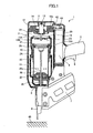
- the combustion-type power tool 1 has a housing 2 constituting an outer frame and including a main housing 2A and a canister housing 2B juxtaposed thereto.
- the main housing 2A is formed with an exhaust port (not shown).
- a head cover 3 formed with an intake port (not shown) is mounted on the top of the main housing 2A.
- a gas canister 4 is detachably accommodated in the canister housing 2B.
- the gas canister 4 contains therein a combustible liquidized gas and has a gauging section 4A and an injection rod 4C extending therefrom.
- a handle 5 extends from a side of the canister housing 2B.
- the handle 5 has a trigger switch 6.
- a magazine 7 and a tail cover 8 are disposed below the housing 2.
- the magazine 7 is adapted for containing therein nails (not shown), and the tail cover 8 is adapted for feeding the nail in the magazine 7 and setting the nail to a predetermined position.
- a push lever 9 is movably provided at a lower end of the main housing 2A.
- the push lever 9 has a tip end adapted to be pressed against a workpiece 40, and has an upper end portion associated with a link member 11 fixed to a combustion chamber frame 10 described later.
- a compression coil spring 30 is interposed between the link member 11 and a cylinder 20 (described later) for normally urging the push lever 9 in a protruding direction away from the head cover 3.
- a cylinder head 12 is secured to the top of the main housing 2A for closing the open top end of the main housing 2A.
- the cylinder head 12 supports a motor 13 at a position opposite to a combustion chamber 23 described later.
- an ignition plug 14 is also supported to the cylinder head 12 at a position adjacent to the motor 13.
- the ignition plug 14 has an ignition spot exposed to the combustion chamber 23.
- the cylinder head 12 has a gas canister side in which is formed a fuel injection passage 12a which allows a combustible gas to pass therethrough.
- One end of the fuel injection passage 12a serves as an injection port that opens at the lower surface of the cylinder head 12.
- Another end of the fuel injection passage 12a constitutes a gas canister connecting portion which is fluidly connected to the injection rod 4C.
- the cylinder head 12 is formed with a disk like, annular groove 12b having an end face 31.
- the end face 31 defines an upper contour of the combustion chamber 23.
- the cylinder head 12 has a disk like annular surface 12C surrounding the groove 12b.
- a motor boss 32 in which a motor 8 is stored protrudes from the end face 31 toward the combustion chamber 23.
- An ignition ground holding portion 33 protrudes from the end face 31 and extends in a generally radial direction.
- An ignition ground 34 is attached to the ignition ground holding portion 25 at a position in confrontation with the ignition plug 14.
- the ignition plug 14 is ignitable upon manipulation to the trigger switch 6 and upon movement of the combustion chamber frame 10 to its predetermined position because of the pressing of the push lever 9 against the workpiece 40.
- the motor 13 has a fan shaft 13A, and a fan 15 positioned in the combustion chamber 23 is fixed to a tip end of the fan shaft 13A.
- a head switch (not shown) is provided in the main housing 2A for detecting an uppermost stroke end position of the combustion chamber frame 10 when the combustion-type power tool 1 is pressed against the workpiece 40.
- the head switch can be turned ON when the push lever 9 is elevated to a predetermined position for starting rotation of the motor 13.
- the combustion chamber frame 10 is provided in the main housing 2A and is movable in the lengthwise direction thereof.
- the combustion chamber frame 10 is moved interlockingly in accordance with the movement of the push lever 9, since the lower end portion of the combustion chamber frame 10 is connected to the link member 11.
- the cylinder 20 is fixed to the main housing 2A.
- the combustion chamber frame 10 has an inner surface in sliding contact with the cylinder 20.
- the cylinder 20 guides movement of the combustion chamber frame 10.
- the cylinder 20 has an axially intermediate portion formed with an exhaust hole 20a.
- An exhaust-gas check valve (not shown) is provided to selectively close the exhaust hole 20a.
- a piston 21 is slidably and reciprocally provided in the cylinder 20.
- the piston 21 divides an inner space of the cylinder 20 into an upper space above the piston 21 and a lower space below the piston 21.
- a bumper 22 is provided on the bottom of the cylinder 20.
- the bumper 22 is made from a resilient material. When the piston 21 moves to its bottom dead center, the piston 21 is abuttable on the bumper 22.
- a first flow passage 24 in communication with an atmosphere is provided between the combustion chamber frame 10 and the cylinder head 12
- a second flow passage 25 in communication with the first flow passage 24 is also provided between the combustion chamber frame 10 and the upper end portion of the cylinder 20.
- These flow passages 24, 25 allow a combustion gas and a fresh air to pass along the outer peripheral surface of the cylinder 20 for discharging these gas through the exhaust port (not shown) of the main housing 2A.
- the above-described intake port (not shown) of the head cover 3 is formed for supplying a fresh air into the combustion chamber 23, and the exhaust hole 20a is adapted for discharging combustion gas generated in the combustion chamber 23.
- a plurality of ribs 10A protrudes radially inwardly from the portion of the combustion chamber frame 10, the portion defining the combustion chamber 23.
- Each rib 10A extends in the axial direction of the combustion chamber frame 10. The ribs 10A promote stirring and mixing of the air and the combustible gas in the combustion chamber 23 in cooperation with the fan 15.
- Rotation of the fan 15 performs the following three functions.
- the fan 15 stirs and mixes the air with the combustible gas as long as the combustion chamber frame 10 remains in abutment with the cylinder head 12.
- the fan 15 causes turbulent combustion of the air-fuel mixture, thus promoting the combustion of the air-fuel mixture in the combustion chamber 23.
- the fan 15 performs scavenging such that the exhaust gas in the combustion chamber 23 can be scavenged therefrom and also performs cooling to the combustion chamber frame 10 and the cylinder 20 when the combustion chamber frame 10 moves away from the cylinder head 12 and when the first and second flow passages 24, 25 are provided.
- a driver blade 26 extends downwards from a side of the piston 21, the side being at the cylinder space below the piston 21, toward the lower end of the main housing 2A.
- the driver blade 26 is positioned coaxially with the nail set in the tail cover 8, so that the driver blade 26 can strike against the nail during movement of the piston 21 toward its bottom dead center.
- the tip end of the driver blade 26 strikes against the nail, and the piston 21 abuts on the bumper 22 and stops. In this case, the bumper 22 absorbs a surplus energy of the piston 21.
- the push lever 9 is biased away from the cylinder head 12 as shown in Fig. 1 by the biasing force of the compression coil spring 30, so that the push lever 9 protrudes from the lower end of the tail cover 8.
- the uppermost end portion of the combustion chamber frame 10 is spaced away from the cylinder head 12 because the link member 11 connects the combustion chamber frame 10 to the push lever 9.
- a part of the combustion chamber frame 10 which the part defines the combustion chamber 23 is also spaced away from the top portion of the cylinder 20.
- the first and second flow passages 24 and 25 are provided. In this condition, the piston 21 stays at its top dead center in the cylinder 20.
- the gas canister 4 is tiltingly moved toward the cylinder head 12 by way of a cam mechanism (not shown).
- the injection rod 4C of the gas canister 4 is pressed against the gas canister connecting portion of the cylinder head 12, so that the combustible liquidized gas in the gas canister 4 is injected into the combustion chamber 23 through the gauging section 4A and the fuel injection passage 12a.
- the combustion chamber frame 10 reaches its uppermost stroke end whereupon the head switch is turned ON to energize the motor 13 for starting rotation of the fan 15.
- Rotation of the fan 15 stirs and mixes the combustible gas with air in the combustion chamber 23 in cooperation with the plurality of ribs 10A.
- the piston 21 strikes against the bumper 22, the cylinder space above the piston 21 becomes communicated with the exhaust hole 20a.
- the high pressure and high temperature combustion gas is discharged out of the cylinder 20 through the exhaust hole 20a of the cylinder 20 and through the check valve (not shown) provided at the exhaust hole 20a to the atmosphere to lower the pressure in the combustion chamber 23.
- the check valve is closed. Combustion gas still remaining in the cylinder 20 and the combustion chamber 23 has a high temperature at a phase immediately after the combustion.
- the high temperature can be absorbed into the walls of the cylinder 20 and the combustion chamber frame 10. Absorption of the heat into the cylinder 20 etc. causes rapid cooling to the combustion gas.
- the pressure in the sealed space in the cylinder 20 above the piston 21 further drops to less than the atmospheric pressure creating a so-called "thermal vacuum". Accordingly, the piston 21 can be moved back to the initial top dead center position.
- the trigger switch 6 is turned OFF, and the user lifts the combustion-type power tool 1 from the workpiece 40 for separating the push lever 9 from the workpiece 40.
- the push lever 9 and the combustion chamber frame 10 move away from the cylinder head 12 because of the biasing force of the compression coil spring 30 to restore a state shown in Fig. 1.
- the first and second flow passages 24 and 25 are provided.
- the fan 15 is configured to keep rotating for a predetermined period of time after the detection of the predetermined position of the combustion chamber frame 10 by the head switch in spite of OFF state of the trigger switch 6.
- fresh air is sucked into the combustion chamber 23 through the intake port formed at the head cover 3 by the rotation of the fan 15.
- the combustion gas is urged to flow through the first and second flow passages 24, 25, and is discharged to the atmosphere through the exhaust port formed in the main housing 2A.
- the combustion chamber 23 is scavenged.
- the rotation of the fan 15 is stopped to restore an initial stationary state. Thereafter, subsequent nail driving operation can be performed by repeating the above described operation process.
- the spark generated between the end of the ignition plug 14 and the ignition ground 34 must not be blown out by a flow of air-fuel mixture provided by the rotation of the fan 15.
- rotation number of the fan 15 or a configuration of blades of the fan 15 are configured to avoid accidental blow-out.
- air-fuel agitation performance, combustion energy and gas blowing performance may be lowered.
- an object of the present invention to provide a combustion type power tool provided with an arrangement that improves ignitability capable of maintaining a spark at the ignition plug against the fan flow of air-fuel mixture without lowering the performance of the fan.
- a combustion-type power tool including a housing, a cylinder, a piston, a combustion chamber frame, a fan, an ignition unit, and a protecting member.
- the housing has one end.
- the cylinder head is disposed at the one end and formed with a fuel injection passage.
- the cylinder is disposed in and fixed to the housing.
- the cylinder defines an axial direction.
- the piston is slidably disposed in the cylinder and reciprocally movable in the axial direction.
- the combustion chamber frame is disposed in the housing and movable in the axial direction.
- the combustion chamber frame is abuttable on the cylinder head to provide a combustion chamber in cooperation with the cylinder head and the piston.
- the fan is rotatably disposed in the combustion chamber for agitating and mixing an air with a combustible gas injected into the combustion chamber through the fuel injection passage.
- the ignition unit includes an ignition plug exposed to the combustion chamber, and an ignition ground.
- the ignition unit generates a spark between the ignition plug and the ignition ground to ignite a mixture of air and the combustible gas, to thus provide a fire.
- the protecting member protects the fire against a flow of the mixture of air and the combustible gas. The flow is provided by the rotation of the fan.
- an ignition arrangement in a combustion type power tool in which a fan is provided in a combustion chamber defined by a cylinder head, a movable combustion chamber frame, a cylinder and a piston, a motive power of the piston being generated upon combustion of a mixture of air and a combustible gas in the combustion chamber.
- the ignition arrangement includes an ignition plug, an ignition ground, and a protecting member. The ignition plug is exposed to the combustion chamber.
- the ignition ground is disposed in the combustion chamber and generates a spark between the ignition plug and the ignition ground to ignite the mixture to thus provide a fire.
- the protecting member is disposed in the combustion chamber that protects the fire against a flow of the mixture provided by the rotation of the fan.
- a combustion-type power tool including a housing, a combustion chamber, a fan, an ignition unit, and a flow speed decreasing member.
- the housing defines an outer frame.
- the combustion chamber is provided in the housing.
- the fan is provided in the combustion chamber and mixes an air with a combustible gas injected into the combustion chamber.
- the ignition unit includes an ignition plug and an ignition ground.
- the ignition unit is provided in the combustion chamber.
- the flow speed decreasing member decreases a flow speed of a mixture of the air and the combustion gas running through a area between the ignition plug and the ignition ground.
- a combustion type power tool according to a first embodiment of the present invention will be described with reference to Fig. 4.
- a structure of the power tool is substantially the same as that of the conventional power tool shown in Figs. 1 through 3 except for an arrangement for protecting a spark against a fan flow. Further, fundamental operation of combustion and scavenging are the same as those of the conventional operation. The same reference numeral is applied to each element as like element of the conventional power tool shown in Figs. 1 through 3.
- Fig. 4 is a perspective view particularly showing a head cover 12 as viewed from a side of a combustion chamber as indicated by an arrow A in Fig. 3.
- the motor boss 32 has an outer peripheral surface 32A and an end portion 32B from which the fan shaft 13A extends.
- a first shelter wall 35A and a second shelter wall 358 are disposed to partially surround an area between the ignition plug 14 and the ignition ground 34.
- Two gaps 36, 36 are provided between the first and second shelter walls 35A and 35B.
- the first shelter wall 35A extends radially outwardly from the outer peripheral surface 32A of the motor boss 32, and also protrudes from the end face 31 in an axial direction of the fan shaft 13A.
- the first shelter wall 35A has a lower end surface inclined such that an axial length between the end face 31 and the lower end surface is gradually reduced toward radially outer end of the first shelter wall 35A.
- the inclined end surface and the gaps 36 are required to perform cleaning to the ignition plug 9 and the ignition ground 24 and to a portion ambient thereto.
- the second shelter wall 35B extends in a circumferential direction and protrudes from the annular surface 12C in the axial direction.
- the second shelter wall 35B is joined to a radially outer end of the ignition ground holding portion 33 so that these are integral with each other. Since the first and second shelter walls 35A and 35B are adapted to mostly surround the area between the ignition plug 14 and the ignition ground 34, a speed of air-fuel mixture running through the area can be reduced. This can prevent a fire generated by the spark from being blown off by the fan flow of air-fuel mixture. Accordingly, stabilized ignitability is attainable, and stable combustion can result.
- FIG. 5 An essential portion of a combustion-type power tool according to a second embodiment is shown in Fig. 5, wherein the same reference numeral is applied to each element as like element in Fig. 4.
- one piece shelter wall 35C protrudes from the annular surface 12C in the axial direction of the fan shaft 13A.
- the shelter wall 35C is integral with an ignition ground holding portion 133 having the ignition ground 34.
- the ignition ground holding portion 13.3 extends radially outwardly from the outer peripheral surface 32A of the motor boss 32, and also protrudes from the end face 31 in an axial direction of the fan shaft 13A.
- the single shelter wall 35C surrounds the area between the ignition plug 14 and the ignition ground 34.
- An inverted U-shaped notched portion 35d is formed at a circumferentially extending portion of the shelter wall 35C, and another inverted U-shaped notched portion 35d is formed at a boundary between the shelter wall 35C and the ignition ground holding portion 133.
- the lower surface of the notched portion 35d is positioned at the lower side than the end face 31.
- the notched portions 35d is functionally equivalent to the gaps 36 of the first embodiment for facilitating cleaning to the ignition plug 14 and the ignition ground 34 and to a region ambient thereto.
- a head cover 12 is engraved from the side of the end face 31 to provide a recessed space 12d.
- the recess 12d is defined by a pair of side walls extending in the axial direction of the fan shaft 13A and a bottom wall.
- One of the side walls serves as an ignition ground holding portion 233 to which the ignition ground 34 is held.
- the ignition plug 14 is exposed to the combustion chamber 23 (Fig. 3) through the bottom of the recess 12d. Since the ignition point of the ignition plug 14 and the ignition ground 34 are disposed within the recessed space 12d, the side walls of the recess 12d can serves as shelter walls.
- a speed of air-fuel mixture running through the area between the ignition plug 14 and the ignition ground 34 can be reduced. This can prevent or restrain a fire generated by the spark from being blown off by the fan flow of air-fuel mixture. Accordingly, stabilized ignitability is attainable, and stable combustion can result.
- FIG. 7 An essential portion of a combustion type power tool according to a fourth embodiment is shown in Fig. 7.
- This embodiment pertains to an improvement on the third embodiment in that one of the side walls 38 of the recess 12d formed in a head cover 12 is formed of arcuate-shaped. Since one of the side walls 38 is formed of arcuate-shaped, a cross-sectional area of the ignition plug 14 side of the recess 12d in the axial direction of the fan shaft 13A is larger than that of the combustion chamber 23 side of the recess 12d. This arcuate side wall 38 of the recess 12d can facilitate cleaning to the ignition plug 14 and the ignition ground 34 and a portion ambient thereto.
- FIG. 8 An essential portion of a combustion type power tool according to a fifth embodiment is shown in Fig. 8.
- This embodiment pertains to an improvement on the fourth embodiment, such that an ignition ground 34 is attached to an outer peripheral surface 32A of the motor boss 32 and within the recess 12d. With this arrangement, the ignition ground 34 itself can also serve as a shelter wall.
- FIG. 9 An essential portion of a combustion type power tool according to a sixth embodiment is shown in Fig. 9.
- This embodiment includes the ignition plug 14, the ignition ground holding portion 33 and the ignition ground 34 those being the same as those shown in Fig. 2.
- This embodiment further includes a shelter cover 39 fixed to the outer peripheral surface 32A of the motor boss 32 for covering the ignition ground holding portion 33, the ignition ground 34, and an ignition point of the ignition plug 14.
- the shelter cover 39 is formed with a plurality of communication holes 39a.
- a gap 40 is provided between the end face 31 and the shelter cover 39. These communication holes 39a and the gap 40 are adapted for allowing air-fuel mixture to pass threrethrough in order to expose the ignition unit to the air-fuel mixture within the shelter cover 39.
- the shelter cover 39 can block a flow of air-fuel mixture that may blow off a flame generated between the ignition plug and the ignition ground.
- a combustion chamber frame 10 (Fig. 3) has an upper horizontal surface portion 10B.
- An ignition ground holding portion 633 radially outwardly extends from the outer peripheral surface of the motor boss 2.3, and the ignition ground 34 is attached to the ignition ground holding portion 633.
- a shelter wall 635 extends from the outer peripheral surface 32A of the motor boss 32 at a position opposite to the ignition ground holding portion 633 with respect to the ignition plug 14.
- Another shelter wall 41 protrudes from the upper horizontal surface portion 10B of the combustion chamber frame 10 in the axial direction of the fan shaft 13A.
- the other shelter wall 41 extends in the circumferential direction of the fan and has one end positioned close to the ignition ground holding portion 633 when the combustion chamber frame 10 is positioned to provide a sealed combustion chamber 23.
- blow-off of a fire generated by the spark by the fan flow of air-fuel mixture can be restrained thereby providing a stabilized ignitability, yet maintaining sufficient performance of the fan to provide high agitation performance, high combustion energy and high gas flowing performance.
- the foregoing embodiments would provide advantage over the conventional arrangement shown in Fig. 2 where only the ignition ground 34 and the ignition ground holding section 33 are provided around the ignition plug 14 without shelter wall(s). Only the ignition ground 34 and the ignition ground holding section 3.3 may be insufficient to prevent or restrain a flow of air-fuel mixture from directing toward the spark generated between the spark plug 14 and the ignition ground 34. Therefore, the flow of air-fuel mixture may blow out the spark.
- the present embodiments can obviate such conventional drawback.
- the side wall 38 may be in a form of arcuate-shaped. That is, a radial distance between the confronting side walls 233, 38 is gradually reduced in a direction away from the combustion chamber and in the axial direction of the fan shaft 13A.
Abstract
Description
- The present invention relates to a combustion-type power tool, and more particularly, to such power tool capable of driving a fastener of driving such as a nail, an anchor, and a staple into a workpiece by igniting a mixture of air and gaseous fuel, which in turn causes a linear momentum of a piston.
- Conventional combustion-type power tools are described in U.S. Patent Nos. USP5,194,646 and USP4,522,162. A conventional combustion-type power tool according will be described with reference to Figs. 1 through 3. Throughout the specification, the term "upper" and "lower" are used assuming that the combustion-type power tool is oriented in a vertical direction. The combustion-type power tool 1 has a
housing 2 constituting an outer frame and including amain housing 2A and acanister housing 2B juxtaposed thereto. Themain housing 2A is formed with an exhaust port (not shown). Ahead cover 3 formed with an intake port (not shown) is mounted on the top of themain housing 2A. A gas canister 4 is detachably accommodated in thecanister housing 2B. The gas canister 4 contains therein a combustible liquidized gas and has agauging section 4A and aninjection rod 4C extending therefrom. - A
handle 5 extends from a side of thecanister housing 2B. Thehandle 5 has a trigger switch 6. Amagazine 7 and atail cover 8 are disposed below thehousing 2. Themagazine 7 is adapted for containing therein nails (not shown), and thetail cover 8 is adapted for feeding the nail in themagazine 7 and setting the nail to a predetermined position. Apush lever 9 is movably provided at a lower end of themain housing 2A. Thepush lever 9 has a tip end adapted to be pressed against aworkpiece 40, and has an upper end portion associated with alink member 11 fixed to acombustion chamber frame 10 described later. Acompression coil spring 30 is interposed between thelink member 11 and a cylinder 20 (described later) for normally urging thepush lever 9 in a protruding direction away from thehead cover 3. - When the
housing 2 is pressed toward theworkpiece 40 while thepush lever 9 is in abutment with theworkpiece 40 against a biasing force of thecompression coil spring 30, an upper portion of thepush lever 9 is retractable into themain housing 2A. - A
cylinder head 12 is secured to the top of themain housing 2A for closing the open top end of themain housing 2A. Thecylinder head 12 supports amotor 13 at a position opposite to acombustion chamber 23 described later. Further, anignition plug 14 is also supported to thecylinder head 12 at a position adjacent to themotor 13. Theignition plug 14 has an ignition spot exposed to thecombustion chamber 23. Thecylinder head 12 has a gas canister side in which is formed afuel injection passage 12a which allows a combustible gas to pass therethrough. One end of thefuel injection passage 12a serves as an injection port that opens at the lower surface of thecylinder head 12. Another end of thefuel injection passage 12a constitutes a gas canister connecting portion which is fluidly connected to theinjection rod 4C. - As shown in Fig. 2, the
cylinder head 12 is formed with a disk like,annular groove 12b having anend face 31. Theend face 31 defines an upper contour of thecombustion chamber 23. Thecylinder head 12 has a disk likeannular surface 12C surrounding thegroove 12b. Amotor boss 32 in which amotor 8 is stored protrudes from theend face 31 toward thecombustion chamber 23. An ignitionground holding portion 33 protrudes from theend face 31 and extends in a generally radial direction. Anignition ground 34 is attached to the ignitionground holding portion 25 at a position in confrontation with theignition plug 14. - The
ignition plug 14 is ignitable upon manipulation to the trigger switch 6 and upon movement of thecombustion chamber frame 10 to its predetermined position because of the pressing of thepush lever 9 against theworkpiece 40. Themotor 13 has afan shaft 13A, and afan 15 positioned in thecombustion chamber 23 is fixed to a tip end of thefan shaft 13A. - A head switch (not shown) is provided in the
main housing 2A for detecting an uppermost stroke end position of thecombustion chamber frame 10 when the combustion-type power tool 1 is pressed against theworkpiece 40. The head switch can be turned ON when thepush lever 9 is elevated to a predetermined position for starting rotation of themotor 13. - The
combustion chamber frame 10 is provided in themain housing 2A and is movable in the lengthwise direction thereof. Thecombustion chamber frame 10 is moved interlockingly in accordance with the movement of thepush lever 9, since the lower end portion of thecombustion chamber frame 10 is connected to thelink member 11. Thecylinder 20 is fixed to themain housing 2A. Thecombustion chamber frame 10 has an inner surface in sliding contact with thecylinder 20. Thus, thecylinder 20 guides movement of thecombustion chamber frame 10. Thecylinder 20 has an axially intermediate portion formed with anexhaust hole 20a. An exhaust-gas check valve (not shown) is provided to selectively close theexhaust hole 20a. - A
piston 21 is slidably and reciprocally provided in thecylinder 20. Thepiston 21 divides an inner space of thecylinder 20 into an upper space above thepiston 21 and a lower space below thepiston 21. Further, abumper 22 is provided on the bottom of thecylinder 20. Thebumper 22 is made from a resilient material. When thepiston 21 moves to its bottom dead center, thepiston 21 is abuttable on thebumper 22. - As shown in Fig. 3, when the upper end of the
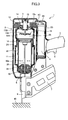
combustion chamber frame 10 abuts on thecylinder head 12, thecylinder head 12, thecombustion chamber frame 10, and the upper cylinder space above thepiston 21 define in combustion thecombustion chamber 23. - As shown in Fig. 3, when the upper end of the
combustion chamber frame 10 is separated from thecylinder head 12, afirst flow passage 24 in communication with an atmosphere is provided between thecombustion chamber frame 10 and thecylinder head 12, and asecond flow passage 25 in communication with thefirst flow passage 24 is also provided between thecombustion chamber frame 10 and the upper end portion of thecylinder 20. Theseflow passages cylinder 20 for discharging these gas through the exhaust port (not shown) of themain housing 2A. Further, the above-described intake port (not shown) of thehead cover 3 is formed for supplying a fresh air into thecombustion chamber 23, and theexhaust hole 20a is adapted for discharging combustion gas generated in thecombustion chamber 23. - A plurality of
ribs 10A protrudes radially inwardly from the portion of thecombustion chamber frame 10, the portion defining thecombustion chamber 23. Eachrib 10A extends in the axial direction of thecombustion chamber frame 10. Theribs 10A promote stirring and mixing of the air and the combustible gas in thecombustion chamber 23 in cooperation with thefan 15. - Rotation of the
fan 15 performs the following three functions. First, thefan 15 stirs and mixes the air with the combustible gas as long as thecombustion chamber frame 10 remains in abutment with thecylinder head 12. Second, after the mixed gas has been ignited, thefan 15 causes turbulent combustion of the air-fuel mixture, thus promoting the combustion of the air-fuel mixture in thecombustion chamber 23. Third, thefan 15 performs scavenging such that the exhaust gas in thecombustion chamber 23 can be scavenged therefrom and also performs cooling to thecombustion chamber frame 10 and thecylinder 20 when thecombustion chamber frame 10 moves away from thecylinder head 12 and when the first andsecond flow passages - A
driver blade 26 extends downwards from a side of thepiston 21, the side being at the cylinder space below thepiston 21, toward the lower end of themain housing 2A. Thedriver blade 26 is positioned coaxially with the nail set in thetail cover 8, so that thedriver blade 26 can strike against the nail during movement of thepiston 21 toward its bottom dead center. When thepiston 21 moves to its bottom dead center, the tip end of thedriver blade 26 strikes against the nail, and thepiston 21 abuts on thebumper 22 and stops. In this case, thebumper 22 absorbs a surplus energy of thepiston 21. - Next, operation of the combustion-type power tool 1 will be described. In the non-operational state of the combustion-type power tool 1, the
push lever 9 is biased away from thecylinder head 12 as shown in Fig. 1 by the biasing force of thecompression coil spring 30, so that thepush lever 9 protrudes from the lower end of thetail cover 8. Thus, the uppermost end portion of thecombustion chamber frame 10 is spaced away from thecylinder head 12 because thelink member 11 connects thecombustion chamber frame 10 to thepush lever 9. Further, a part of thecombustion chamber frame 10 which the part defines thecombustion chamber 23 is also spaced away from the top portion of thecylinder 20. Hence, the first andsecond flow passages piston 21 stays at its top dead center in thecylinder 20. - With this state, if the
push lever 9 is pushed onto theworkpiece 40 while holding thehandle 5 by a user as shown in Fig. 3, thepush lever 9 is moved toward thecylinder head 12 against the biasing force of thecompression coil spring 30. At the same time, thecombustion chamber frame 10 which is associated with thepush lever 9 through thelink member 11 is also moved toward thecylinder head 12, closing the above-describedflow passages combustion chamber 23 is provided. - In accordance with the movement of the
push lever 9, the gas canister 4 is tiltingly moved toward thecylinder head 12 by way of a cam mechanism (not shown). Thus, theinjection rod 4C of the gas canister 4 is pressed against the gas canister connecting portion of thecylinder head 12, so that the combustible liquidized gas in the gas canister 4 is injected into thecombustion chamber 23 through the gaugingsection 4A and thefuel injection passage 12a. - Further, in accordance with the movement of the
push lever 9, thecombustion chamber frame 10 reaches its uppermost stroke end whereupon the head switch is turned ON to energize themotor 13 for starting rotation of thefan 15. Rotation of thefan 15 stirs and mixes the combustible gas with air in thecombustion chamber 23 in cooperation with the plurality ofribs 10A. - In this state, when the trigger switch 6 provided at the
handle 5 is turned ON, spark is generated between the end of theignition plug 14 and the ignition ground 34 to ignite the combustible gas. The combusted and expanded gas pushes thepiston 21 to its bottom dead center. Therefore, a nail in thetail cover 8 is driven into theworkpiece 40 by thedriver blade 26 until thepiston 21 abuts on thebumper 22. - After the nail driving, the
piston 21 strikes against thebumper 22, the cylinder space above thepiston 21 becomes communicated with theexhaust hole 20a. Thus, the high pressure and high temperature combustion gas is discharged out of thecylinder 20 through theexhaust hole 20a of thecylinder 20 and through the check valve (not shown) provided at theexhaust hole 20a to the atmosphere to lower the pressure in thecombustion chamber 23. When the inner space of thecylinder 20 and thecombustion chamber 23 becomes the atmospheric pressure, the check valve is closed. Combustion gas still remaining in thecylinder 20 and thecombustion chamber 23 has a high temperature at a phase immediately after the combustion. However, the high temperature can be absorbed into the walls of thecylinder 20 and thecombustion chamber frame 10. Absorption of the heat into thecylinder 20 etc. causes rapid cooling to the combustion gas. Thus, the pressure in the sealed space in thecylinder 20 above thepiston 21 further drops to less than the atmospheric pressure creating a so-called "thermal vacuum". Accordingly, thepiston 21 can be moved back to the initial top dead center position. - Then, the trigger switch 6 is turned OFF, and the user lifts the combustion-type power tool 1 from the
workpiece 40 for separating thepush lever 9 from theworkpiece 40. As a result, thepush lever 9 and thecombustion chamber frame 10 move away from thecylinder head 12 because of the biasing force of thecompression coil spring 30 to restore a state shown in Fig. 1. Thus, the first andsecond flow passages fan 15 is configured to keep rotating for a predetermined period of time after the detection of the predetermined position of thecombustion chamber frame 10 by the head switch in spite of OFF state of the trigger switch 6. Thus, in the state shown in Fig. 1, fresh air is sucked into thecombustion chamber 23 through the intake port formed at thehead cover 3 by the rotation of thefan 15. Thus, the combustion gas is urged to flow through the first andsecond flow passages main housing 2A. Thus, thecombustion chamber 23 is scavenged. Then, the rotation of thefan 15 is stopped to restore an initial stationary state. Thereafter, subsequent nail driving operation can be performed by repeating the above described operation process. - In the conventional combustion-type power tool 1, the spark generated between the end of the
ignition plug 14 and theignition ground 34 must not be blown out by a flow of air-fuel mixture provided by the rotation of thefan 15. To this effect, conventionally, rotation number of thefan 15 or a configuration of blades of thefan 15 are configured to avoid accidental blow-out. However, air-fuel agitation performance, combustion energy and gas blowing performance may be lowered. - It is therefore, an object of the present invention to provide a combustion type power tool provided with an arrangement that improves ignitability capable of maintaining a spark at the ignition plug against the fan flow of air-fuel mixture without lowering the performance of the fan.
- This and other object of the present invention will be attained by a combustion-type power tool including a housing, a cylinder, a piston, a combustion chamber frame, a fan, an ignition unit, and a protecting member.
- The housing has one end. The cylinder head is disposed at the one end and formed with a fuel injection passage. The cylinder is disposed in and fixed to the housing. The cylinder defines an axial direction. The piston is slidably disposed in the cylinder and reciprocally movable in the axial direction. The combustion chamber frame is disposed in the housing and movable in the axial direction. The combustion chamber frame is abuttable on the cylinder head to provide a combustion chamber in cooperation with the cylinder head and the piston. The fan is rotatably disposed in the combustion chamber for agitating and mixing an air with a combustible gas injected into the combustion chamber through the fuel injection passage. The ignition unit includes an ignition plug exposed to the combustion chamber, and an ignition ground. The ignition unit generates a spark between the ignition plug and the ignition ground to ignite a mixture of air and the combustible gas, to thus provide a fire. The protecting member protects the fire against a flow of the mixture of air and the combustible gas. The flow is provided by the rotation of the fan.
- In another aspect of the invention, there is provided an ignition arrangement in a combustion type power tool in which a fan is provided in a combustion chamber defined by a cylinder head, a movable combustion chamber frame, a cylinder and a piston, a motive power of the piston being generated upon combustion of a mixture of air and a combustible gas in the combustion chamber. The ignition arrangement includes an ignition plug, an ignition ground, and a protecting member. The ignition plug is exposed to the combustion chamber. The ignition ground is disposed in the combustion chamber and generates a spark between the ignition plug and the ignition ground to ignite the mixture to thus provide a fire. The protecting member is disposed in the combustion chamber that protects the fire against a flow of the mixture provided by the rotation of the fan.
- In another aspect of the invention, there is provided a combustion-type power tool including a housing, a combustion chamber, a fan, an ignition unit, and a flow speed decreasing member.
- The housing defines an outer frame. The combustion chamber is provided in the housing. The fan is provided in the combustion chamber and mixes an air with a combustible gas injected into the combustion chamber. The ignition unit includes an ignition plug and an ignition ground. The ignition unit is provided in the combustion chamber. The flow speed decreasing member decreases a flow speed of a mixture of the air and the combustion gas running through a area between the ignition plug and the ignition ground.
- In the drawings;
- Fig. 1 is a schematic side view partly cross-sectioned showing a conventional combustion-type power tool and shows an initial state prior to fastener driving operation;
- Fig. 2 is a perspective view as viewed from the combustion chamber side as indicated by an arrow A in Fig. 1.
- Fig. 3 is a schematic side view partly cross-sectioned showing the conventional combustion-type power tool and shows a state where a sealed combustion chamber is provided in the fastener driving operation;
- Fig. 4 is a perspective view showing an arrangement for protecting a spark against a fan flow in a combustion-type power tool according to a first embodiment of the present invention;
- Fig. 5 is a perspective view showing an arrangement for protecting a spark against a fan flow in a combustion-type power tool according to a second embodiment of the present invention;
- Fig. 6 is a perspective view showing an arrangement for protecting a spark against a fan flow in a combustion-type power tool according to a third embodiment of the present invention;
- Fig. 7 is a perspective view showing an arrangement for protecting a spark against a fan flow in a combustion-type power tool according to a fourth embodiment of the present invention;
- Fig. 8 is a perspective view showing an arrangement for protecting a spark against a fan flow in a combustion-type power tool according to a fifth embodiment of the present invention;
- Fig. 9 is a perspective view showing an arrangement for protecting a spark against a fan flow in a combustion-type power tool according to a sixth embodiment of the present invention; and
- Fig. 10 is a perspective view showing an arrangement for protecting a spark against a fan flow in a combustion-type power tool according to a seventh embodiment of the present invention.
- A combustion type power tool according to a first embodiment of the present invention will be described with reference to Fig. 4. A structure of the power tool is substantially the same as that of the conventional power tool shown in Figs. 1 through 3 except for an arrangement for protecting a spark against a fan flow. Further, fundamental operation of combustion and scavenging are the same as those of the conventional operation. The same reference numeral is applied to each element as like element of the conventional power tool shown in Figs. 1 through 3.
- Fig. 4 is a perspective view particularly showing a
head cover 12 as viewed from a side of a combustion chamber as indicated by an arrow A in Fig. 3. Themotor boss 32 has an outerperipheral surface 32A and anend portion 32B from which thefan shaft 13A extends. Afirst shelter wall 35A and a second shelter wall 358 are disposed to partially surround an area between theignition plug 14 and theignition ground 34. Twogaps second shelter walls first shelter wall 35A extends radially outwardly from the outerperipheral surface 32A of themotor boss 32, and also protrudes from theend face 31 in an axial direction of thefan shaft 13A. Thefirst shelter wall 35A has a lower end surface inclined such that an axial length between theend face 31 and the lower end surface is gradually reduced toward radially outer end of thefirst shelter wall 35A. The inclined end surface and thegaps 36 are required to perform cleaning to theignition plug 9 and theignition ground 24 and to a portion ambient thereto. - The
second shelter wall 35B extends in a circumferential direction and protrudes from theannular surface 12C in the axial direction. Thesecond shelter wall 35B is joined to a radially outer end of the ignitionground holding portion 33 so that these are integral with each other. Since the first andsecond shelter walls ignition plug 14 and theignition ground 34, a speed of air-fuel mixture running through the area can be reduced. This can prevent a fire generated by the spark from being blown off by the fan flow of air-fuel mixture. Accordingly, stabilized ignitability is attainable, and stable combustion can result. - An essential portion of a combustion-type power tool according to a second embodiment is shown in Fig. 5, wherein the same reference numeral is applied to each element as like element in Fig. 4. In the second embodiment, one piece shelter wall 35C protrudes from the
annular surface 12C in the axial direction of thefan shaft 13A. The shelter wall 35C is integral with an ignitionground holding portion 133 having theignition ground 34. The ignition ground holding portion 13.3 extends radially outwardly from the outerperipheral surface 32A of themotor boss 32, and also protrudes from theend face 31 in an axial direction of thefan shaft 13A. - The single shelter wall 35C surrounds the area between the
ignition plug 14 and theignition ground 34. An inverted U-shaped notchedportion 35d is formed at a circumferentially extending portion of the shelter wall 35C, and another inverted U-shaped notchedportion 35d is formed at a boundary between the shelter wall 35C and the ignitionground holding portion 133. The lower surface of the notchedportion 35d is positioned at the lower side than theend face 31. The notchedportions 35d is functionally equivalent to thegaps 36 of the first embodiment for facilitating cleaning to theignition plug 14 and theignition ground 34 and to a region ambient thereto. - An essential portion of a combustion type power tool according to a third embodiment is shown in Fig. 6. In the third embodiment, a
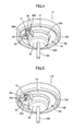
head cover 12 is engraved from the side of theend face 31 to provide a recessedspace 12d. Therecess 12d is defined by a pair of side walls extending in the axial direction of thefan shaft 13A and a bottom wall. One of the side walls serves as an ignitionground holding portion 233 to which theignition ground 34 is held. The ignition plug 14 is exposed to the combustion chamber 23 (Fig. 3) through the bottom of therecess 12d. Since the ignition point of theignition plug 14 and theignition ground 34 are disposed within the recessedspace 12d, the side walls of therecess 12d can serves as shelter walls. Thus, a speed of air-fuel mixture running through the area between theignition plug 14 and theignition ground 34 can be reduced. This can prevent or restrain a fire generated by the spark from being blown off by the fan flow of air-fuel mixture. Accordingly, stabilized ignitability is attainable, and stable combustion can result. - An essential portion of a combustion type power tool according to a fourth embodiment is shown in Fig. 7. This embodiment pertains to an improvement on the third embodiment in that one of the
side walls 38 of therecess 12d formed in ahead cover 12 is formed of arcuate-shaped. Since one of theside walls 38 is formed of arcuate-shaped, a cross-sectional area of theignition plug 14 side of therecess 12d in the axial direction of thefan shaft 13A is larger than that of thecombustion chamber 23 side of therecess 12d. Thisarcuate side wall 38 of therecess 12d can facilitate cleaning to theignition plug 14 and theignition ground 34 and a portion ambient thereto. - An essential portion of a combustion type power tool according to a fifth embodiment is shown in Fig. 8. This embodiment pertains to an improvement on the fourth embodiment, such that an
ignition ground 34 is attached to an outerperipheral surface 32A of themotor boss 32 and within therecess 12d. With this arrangement, theignition ground 34 itself can also serve as a shelter wall. - An essential portion of a combustion type power tool according to a sixth embodiment is shown in Fig. 9. This embodiment includes the
ignition plug 14, the ignitionground holding portion 33 and theignition ground 34 those being the same as those shown in Fig. 2. This embodiment further includes ashelter cover 39 fixed to the outerperipheral surface 32A of themotor boss 32 for covering the ignitionground holding portion 33, theignition ground 34, and an ignition point of theignition plug 14. Theshelter cover 39 is formed with a plurality ofcommunication holes 39a. Agap 40 is provided between theend face 31 and theshelter cover 39. Thesecommunication holes 39a and thegap 40 are adapted for allowing air-fuel mixture to pass threrethrough in order to expose the ignition unit to the air-fuel mixture within theshelter cover 39. Theshelter cover 39 can block a flow of air-fuel mixture that may blow off a flame generated between the ignition plug and the ignition ground. - An essential portion of a combustion type power tool according to a seventh embodiment is shown in Fig. 10. In this embodiment, a combustion chamber frame 10 (Fig. 3) has an upper
horizontal surface portion 10B. An ignitionground holding portion 633 radially outwardly extends from the outer peripheral surface of the motor boss 2.3, and theignition ground 34 is attached to the ignitionground holding portion 633. Ashelter wall 635 extends from the outerperipheral surface 32A of themotor boss 32 at a position opposite to the ignitionground holding portion 633 with respect to theignition plug 14. - Another
shelter wall 41 protrudes from the upperhorizontal surface portion 10B of thecombustion chamber frame 10 in the axial direction of thefan shaft 13A. Theother shelter wall 41 extends in the circumferential direction of the fan and has one end positioned close to the ignitionground holding portion 633 when thecombustion chamber frame 10 is positioned to provide a sealedcombustion chamber 23. - With this arrangement, blow-off of a fire generated by the spark by the fan flow of air-fuel mixture can be restrained thereby providing a stabilized ignitability, yet maintaining sufficient performance of the fan to provide high agitation performance, high combustion energy and high gas flowing performance.
- The foregoing embodiments would provide advantage over the conventional arrangement shown in Fig. 2 where only the
ignition ground 34 and the ignitionground holding section 33 are provided around theignition plug 14 without shelter wall(s). Only theignition ground 34 and the ignition ground holding section 3.3 may be insufficient to prevent or restrain a flow of air-fuel mixture from directing toward the spark generated between thespark plug 14 and theignition ground 34. Therefore, the flow of air-fuel mixture may blow out the spark. The present embodiments can obviate such conventional drawback. - While the invention has been described in detail with reference to specific embodiments thereof, it would be apparent to those skilled in the art that many modifications and variations may be made therein without departing from the spirit of the invention, the scope of which is defined by the attached claims.
- For example, as shown in Figs. 7 and 8, while the
side wall 38 is in a form of arcuate-shaped, theside wall 38 may be in a form of flat surface. That is, a radial distance between the confrontingside walls fan shaft 13A.
Claims (17)
- A combustion-type power tool comprising:a housing having one end;a cylinder head disposed at the one end and formed with a fuel injection passage;a cylinder disposed in and fixed to the housing, the cylinder defining an axial direction;a piston slidably disposed in the cylinder and reciprocally movable in the axial direction;a combustion chamber frame disposed in the housing and movable in the axial direction, the combustion chamber frame being abuttable on the cylinder head to provide a combustion chamber in cooperation with the cylinder head and the piston;a fan rotatably disposed in the combustion chamber for agitating and mixing an air with a combustible gas injected into the combustion chamber through the fuel injection passage;an ignition unit comprising an ignition plug exposed to the combustion chamber, and an ignition ground that generates a spark between the ignition plug and the ignition ground to ignite a mixture of air and the combustible gas, to thus provide a fire; anda protecting member that protects the fire against a flow of the mixture of air and the combustible gas, the flow being provided by the rotation of the fan.
- The combustion-type power tool according to claim 1, wherein the protecting member comprises a shelter wall disposed at a position adjacent to the ignition plug and the ignition ground.
- The combustion-type power tool according to claim 2, wherein the cylinder head is formed with a recess opening to the combustion chamber, a surface of the recess defining the shelter wall, and the ignition plug being exposed to the combustion chamber through a bottom of the recess.
- The combustion-type power tool according to claim 3, wherein the shelter wall has a part in a form of a slant surface that slants with respect to the axial direction of the piston.
- The combustion-type power tool according to claim 1, wherein the protecting member comprises a shelter wall disposed to partially surround an area between the ignition plug and the ignition ground.
- The combustion-type power tool according to claim 5, wherein the shelter wall is formed with a notched portion.
- The combustion-type power tool according to claim 5, wherein the shelter wall has a slant surface that slants with respect to the axial direction of the piston.
- The combustion-type power tool according to claim 1, wherein the protecting member comprises a cover that covers the ignition plug and the ignition ground, the cover providing a gap to allow the mixture to reach the spark.
- An ignition arrangement in a combustion type power tool in which a fan is provided in a combustion chamber defined by a cylinder head, a movable combustion chamber frame, a cylinder and a piston, a motive power of the piston being generated upon combustion of a mixture of air and a combustible gas in the combustion chamber, the arrangement comprising:an ignition plug exposed to the combustion chamber;an ignition ground disposed in the combustion chamber and generating a spark between the ignition plug and the ignition ground to ignite the mixture to thus provide a fire; anda protecting member disposed in the combustion chamber that protects the fire against a flow of the mixture provided by the rotation of the fan.
- The ignition arrangement in a combustion type power tool according to claim 9, wherein the protecting member comprises a shelter wall disposed at a position adjacent to the ignition plug and the ignition ground.
- The ignition arrangement in a combustion type power tool according to claim 10, wherein the cylinder head is formed with a recess opening to the combustion chamber, a surface of the recess defining the shelter wall, and the ignition plug being exposed to the combustion chamber through a bottom of the recess.
- The ignition arrangement in a combustion type power tool according to claim 10, wherein the shelter wall has a part in a form of a slant surface that slants with respect to the axial direction of the piston.
- The ignition arrangement in a combustion type power tool according to claim 9, wherein the protecting member comprises a shelter wall disposed to partially surround an area between the ignition plug and the ignition ground.
- The ignition arrangement in a combustion type power tool according to claim 13, wherein the shelter wall is formed with a notched portion.
- The ignition arrangement in a combustion type power tool according to claim 1.3, wherein the shelter wall has a slant surface that slants with respect to the axial direction of the piston.
- The ignition arrangement in a combustion type power tool according to claim 9, wherein the protecting member comprises a cover that covers the ignition plug and the ignition ground, the cover providing a gap to allow the mixture to reach the spark.
- A combustion-type power tool comprising:a housing defining an outer frame;a combustion chamber provided in the housinga fan provided in the combustion chamber and mixing an air with a combustible gas injected into the combustion chamber;an ignition unit comprising an ignition plug and an ignition ground, the ignition unit provided in the combustion chamber; anda flow speed decreasing member that decreases a flow speed of a mixture of the air and the combustion gas running through a area between the ignition plug and the ignition ground.
Applications Claiming Priority (1)
| Application Number | Priority Date | Filing Date | Title |
|---|---|---|---|
| JP2005043276A JP4446287B2 (en) | 2005-02-18 | 2005-02-18 | Combustion nailer |
Publications (3)
| Publication Number | Publication Date |
|---|---|
| EP1693158A2 true EP1693158A2 (en) | 2006-08-23 |
| EP1693158A3 EP1693158A3 (en) | 2010-04-28 |
| EP1693158B1 EP1693158B1 (en) | 2011-12-28 |
Family
ID=36405928
Family Applications (1)
| Application Number | Title | Priority Date | Filing Date |
|---|---|---|---|
| EP06250878A Expired - Fee Related EP1693158B1 (en) | 2005-02-18 | 2006-02-18 | Combustion-type power tool having ignition proof arrangement |
Country Status (3)
| Country | Link |
|---|---|
| US (1) | US7305940B2 (en) |
| EP (1) | EP1693158B1 (en) |
| JP (1) | JP4446287B2 (en) |
Cited By (2)
| Publication number | Priority date | Publication date | Assignee | Title |
|---|---|---|---|---|
| DE102008000167A1 (en) | 2008-01-29 | 2009-07-30 | Hilti Aktiengesellschaft | Internal combustion setting device |
| EP2397276A1 (en) * | 2007-04-02 | 2011-12-21 | Max Co., Ltd. | Gas internal combustion type nailing machine |
Families Citing this family (6)
| Publication number | Priority date | Publication date | Assignee | Title |
|---|---|---|---|---|
| JP4147403B2 (en) * | 2003-07-31 | 2008-09-10 | マックス株式会社 | Combustion chamber structure of gas-fired impact tool |
| JP5055793B2 (en) * | 2006-03-10 | 2012-10-24 | マックス株式会社 | Gas fired driving tool |
| JP4957897B2 (en) * | 2007-04-02 | 2012-06-20 | マックス株式会社 | Gas internal combustion nailer |
| JP5012176B2 (en) * | 2007-04-27 | 2012-08-29 | マックス株式会社 | Gas internal combustion nailer |
| US8265688B2 (en) * | 2007-12-31 | 2012-09-11 | Motorola Mobility Llc | Wireless communication device and split touch sensitive user input surface |
| FR2953752B1 (en) * | 2009-12-11 | 2012-01-20 | Prospection & Inventions | INTERNAL COMBUSTION ENGINE FIXING TOOL WITH SINGLE CHAMBER OPENING AND CLOSING |
Citations (2)
| Publication number | Priority date | Publication date | Assignee | Title |
|---|---|---|---|---|
| US4522162A (en) | 1981-01-22 | 1985-06-11 | Signode Corporation | Portable gas-powered tool with linear motor |
| US5194646A (en) | 1991-01-16 | 1993-03-16 | Mitsuo Yamada | Polymerizable silicones having acetylenic unsaturation |
Family Cites Families (18)
| Publication number | Priority date | Publication date | Assignee | Title |
|---|---|---|---|---|
| US4091774A (en) * | 1973-12-05 | 1978-05-30 | Minoru Kamiya | Stratified combustion type engine |
| US4176649A (en) * | 1976-05-10 | 1979-12-04 | Toyota Motor Company, Ltd. | Emission control |
| DE2746596C2 (en) * | 1977-10-15 | 1986-07-03 | Robert Bosch Gmbh, 7000 Stuttgart | Spark ignition internal combustion engine |
| US4542724A (en) * | 1982-09-22 | 1985-09-24 | Blais Gordon A | Flame injector for internal combustion engines |
| DE3889038T2 (en) * | 1987-02-19 | 1994-09-08 | Hi Tech International Lab Co L | COMBUSTION SYSTEM FOR AN INTERNAL COMBUSTION ENGINE AND BURNER USED THEREOF. |
| US5197648A (en) * | 1988-11-29 | 1993-03-30 | Gingold Bruce S | Surgical stapling apparatus |
| JPH0325307A (en) | 1989-06-22 | 1991-02-04 | Fuji Electric Co Ltd | External light triangular system distance measuring instrument |
| US5014656A (en) * | 1990-04-25 | 1991-05-14 | General Motors Corporation | Internal combustion engine having a permanent ground electrode and replaceable center electrode element |
| US5105780A (en) * | 1990-08-08 | 1992-04-21 | Caterpillar Inc. | Ignition assisting device for internal combustion engines |
| US5197646A (en) | 1992-03-09 | 1993-03-30 | Illinois Tool Works Inc. | Combustion-powered tool assembly |
| JPH0736985A (en) | 1993-07-15 | 1995-02-07 | Toray Ind Inc | Display body for managing washing and method for managing washing |
| US5799637A (en) * | 1996-05-01 | 1998-09-01 | Cifuni; Charles G. | Rocket effect sparking plug |
| US6138637A (en) * | 1997-09-18 | 2000-10-31 | Daimlerchrysler Ag | Internal combustion engine with direct fuel injection |
| DE10218194B4 (en) * | 2002-04-24 | 2004-05-13 | Hilti Ag | Setting tool that can be driven by expanding gases |
| JP4039269B2 (en) * | 2003-02-21 | 2008-01-30 | 日立工機株式会社 | Combustion power tool |
| EP1484138B1 (en) * | 2003-06-02 | 2009-11-11 | Makita Corporation | Combustion power tool |
| JP4147403B2 (en) * | 2003-07-31 | 2008-09-10 | マックス株式会社 | Combustion chamber structure of gas-fired impact tool |
| JP4144472B2 (en) * | 2003-08-11 | 2008-09-03 | 日立工機株式会社 | Combustion power tool |
-
2005
- 2005-02-18 JP JP2005043276A patent/JP4446287B2/en not_active Expired - Fee Related
-
2006
- 2006-02-17 US US11/356,102 patent/US7305940B2/en not_active Expired - Fee Related
- 2006-02-18 EP EP06250878A patent/EP1693158B1/en not_active Expired - Fee Related
Patent Citations (3)
| Publication number | Priority date | Publication date | Assignee | Title |
|---|---|---|---|---|
| US4522162A (en) | 1981-01-22 | 1985-06-11 | Signode Corporation | Portable gas-powered tool with linear motor |
| US4522162B1 (en) | 1981-01-22 | 1989-03-21 | ||
| US5194646A (en) | 1991-01-16 | 1993-03-16 | Mitsuo Yamada | Polymerizable silicones having acetylenic unsaturation |
Cited By (5)
| Publication number | Priority date | Publication date | Assignee | Title |
|---|---|---|---|---|
| EP2397276A1 (en) * | 2007-04-02 | 2011-12-21 | Max Co., Ltd. | Gas internal combustion type nailing machine |
| EP2397275A1 (en) * | 2007-04-02 | 2011-12-21 | Max Co., Ltd. | Gas internal combustion type nailing machine |
| DE102008000167A1 (en) | 2008-01-29 | 2009-07-30 | Hilti Aktiengesellschaft | Internal combustion setting device |
| EP2085189A2 (en) | 2008-01-29 | 2009-08-05 | HILTI Aktiengesellschaft | Combustion type fastener driving device |
| EP2085189A3 (en) * | 2008-01-29 | 2010-06-23 | HILTI Aktiengesellschaft | Combustion type fastener driving device |
Also Published As
| Publication number | Publication date |
|---|---|
| JP4446287B2 (en) | 2010-04-07 |
| EP1693158A3 (en) | 2010-04-28 |
| US20060186165A1 (en) | 2006-08-24 |
| EP1693158B1 (en) | 2011-12-28 |
| JP2006224268A (en) | 2006-08-31 |
| US7305940B2 (en) | 2007-12-11 |
Similar Documents
| Publication | Publication Date | Title |
|---|---|---|
| EP2061631B1 (en) | Combustion-type power tool | |
| US7305940B2 (en) | Combustion-type power tool having ignition proof arrangement | |
| US7225768B2 (en) | Combustion type power tool having buffer piece | |
| US7490582B2 (en) | Combustion type power tool having fin for effectively cooling cylinder | |
| US7305941B2 (en) | Combustion type power tool having motor suspension arrangement | |
| US7387092B2 (en) | Combustion-type power tool having cooling arrangement | |
| US7931181B2 (en) | Combustion-type power tool with trigger control arrangements | |
| US7458493B2 (en) | Combustion chamber arrangement in combustion type power tool | |
| JP4039269B2 (en) | Combustion power tool | |
| US20060042574A1 (en) | Combustion-type power tool providing specific spark energy | |
| US7131404B2 (en) | Combustion-type power tool having gas canister cooling arrangement | |
| EP1693157B1 (en) | Combustion-type power tool having ignition proof arrangement |
Legal Events
| Date | Code | Title | Description |
|---|---|---|---|
| PUAI | Public reference made under article 153(3) epc to a published international application that has entered the european phase |
Free format text: ORIGINAL CODE: 0009012 |
|
| AK | Designated contracting states |
Kind code of ref document: A2 Designated state(s): AT BE BG CH CY CZ DE DK EE ES FI FR GB GR HU IE IS IT LI LT LU LV MC NL PL PT RO SE SI SK TR |
|
| AX | Request for extension of the european patent |
Extension state: AL BA HR MK YU |
|
| 17P | Request for examination filed |
Effective date: 20090311 |
|
| PUAL | Search report despatched |
Free format text: ORIGINAL CODE: 0009013 |
|
| AK | Designated contracting states |
Kind code of ref document: A3 Designated state(s): AT BE BG CH CY CZ DE DK EE ES FI FR GB GR HU IE IS IT LI LT LU LV MC NL PL PT RO SE SI SK TR |
|
| AX | Request for extension of the european patent |
Extension state: AL BA HR MK YU |
|
| 17Q | First examination report despatched |
Effective date: 20101117 |
|
| AKX | Designation fees paid |
Designated state(s): DE FR GB |
|
| GRAP | Despatch of communication of intention to grant a patent |
Free format text: ORIGINAL CODE: EPIDOSNIGR1 |
|
| RIC1 | Information provided on ipc code assigned before grant |
Ipc: B25C 1/08 20060101AFI20110614BHEP |
|
| GRAS | Grant fee paid |
Free format text: ORIGINAL CODE: EPIDOSNIGR3 |
|
| GRAA | (expected) grant |
Free format text: ORIGINAL CODE: 0009210 |
|
| AK | Designated contracting states |
Kind code of ref document: B1 Designated state(s): DE FR GB |
|
| REG | Reference to a national code |
Ref country code: GB Ref legal event code: FG4D |
|
| REG | Reference to a national code |
Ref country code: DE Ref legal event code: R096 Ref document number: 602006026654 Country of ref document: DE Effective date: 20120308 |
|
| PLBE | No opposition filed within time limit |
Free format text: ORIGINAL CODE: 0009261 |
|
| STAA | Information on the status of an ep patent application or granted ep patent |
Free format text: STATUS: NO OPPOSITION FILED WITHIN TIME LIMIT |
|
| 26N | No opposition filed |
Effective date: 20121001 |
|
| REG | Reference to a national code |
Ref country code: DE Ref legal event code: R097 Ref document number: 602006026654 Country of ref document: DE Effective date: 20121001 |
|
| REG | Reference to a national code |
Ref country code: FR Ref legal event code: PLFP Year of fee payment: 11 |
|
| REG | Reference to a national code |
Ref country code: DE Ref legal event code: R082 Ref document number: 602006026654 Country of ref document: DE Representative=s name: WEICKMANN & WEICKMANN PATENTANWAELTE - RECHTSA, DE Ref country code: DE Ref legal event code: R082 Ref document number: 602006026654 Country of ref document: DE Representative=s name: WEICKMANN & WEICKMANN PATENT- UND RECHTSANWAEL, DE |
|
| PGFP | Annual fee paid to national office [announced via postgrant information from national office to epo] |
Ref country code: DE Payment date: 20160209 Year of fee payment: 11 |
|
| PGFP | Annual fee paid to national office [announced via postgrant information from national office to epo] |
Ref country code: GB Payment date: 20160217 Year of fee payment: 11 Ref country code: FR Payment date: 20160108 Year of fee payment: 11 |
|
| REG | Reference to a national code |
Ref country code: DE Ref legal event code: R119 Ref document number: 602006026654 Country of ref document: DE |
|
| GBPC | Gb: european patent ceased through non-payment of renewal fee |
Effective date: 20170218 |
|
| REG | Reference to a national code |
Ref country code: FR Ref legal event code: ST Effective date: 20171031 |
|
| PG25 | Lapsed in a contracting state [announced via postgrant information from national office to epo] |
Ref country code: DE Free format text: LAPSE BECAUSE OF NON-PAYMENT OF DUE FEES Effective date: 20170901 Ref country code: FR Free format text: LAPSE BECAUSE OF NON-PAYMENT OF DUE FEES Effective date: 20170228 |
|
| PG25 | Lapsed in a contracting state [announced via postgrant information from national office to epo] |
Ref country code: GB Free format text: LAPSE BECAUSE OF NON-PAYMENT OF DUE FEES Effective date: 20170218 |