EP1689062B1 - Apparatus and method for charging a battery through capacitive coupling - Google Patents
Apparatus and method for charging a battery through capacitive coupling Download PDFInfo
- Publication number
- EP1689062B1 EP1689062B1 EP05250617A EP05250617A EP1689062B1 EP 1689062 B1 EP1689062 B1 EP 1689062B1 EP 05250617 A EP05250617 A EP 05250617A EP 05250617 A EP05250617 A EP 05250617A EP 1689062 B1 EP1689062 B1 EP 1689062B1
- Authority
- EP
- European Patent Office
- Prior art keywords
- charger
- portable electronic
- electronic device
- capacitive electrodes
- charging
- Prior art date
- Legal status (The legal status is an assumption and is not a legal conclusion. Google has not performed a legal analysis and makes no representation as to the accuracy of the status listed.)
- Active
Links
Images


Classifications
-
- H—ELECTRICITY
- H02—GENERATION; CONVERSION OR DISTRIBUTION OF ELECTRIC POWER
- H02J—CIRCUIT ARRANGEMENTS OR SYSTEMS FOR SUPPLYING OR DISTRIBUTING ELECTRIC POWER; SYSTEMS FOR STORING ELECTRIC ENERGY
- H02J7/00—Circuit arrangements for charging or depolarising batteries or for supplying loads from batteries
- H02J7/0042—Circuit arrangements for charging or depolarising batteries or for supplying loads from batteries characterised by the mechanical construction
- H02J7/0044—Circuit arrangements for charging or depolarising batteries or for supplying loads from batteries characterised by the mechanical construction specially adapted for holding portable devices containing batteries
-
- H—ELECTRICITY
- H02—GENERATION; CONVERSION OR DISTRIBUTION OF ELECTRIC POWER
- H02J—CIRCUIT ARRANGEMENTS OR SYSTEMS FOR SUPPLYING OR DISTRIBUTING ELECTRIC POWER; SYSTEMS FOR STORING ELECTRIC ENERGY
- H02J50/00—Circuit arrangements or systems for wireless supply or distribution of electric power
- H02J50/05—Circuit arrangements or systems for wireless supply or distribution of electric power using capacitive coupling
-
- H—ELECTRICITY
- H02—GENERATION; CONVERSION OR DISTRIBUTION OF ELECTRIC POWER
- H02J—CIRCUIT ARRANGEMENTS OR SYSTEMS FOR SUPPLYING OR DISTRIBUTING ELECTRIC POWER; SYSTEMS FOR STORING ELECTRIC ENERGY
- H02J50/00—Circuit arrangements or systems for wireless supply or distribution of electric power
- H02J50/10—Circuit arrangements or systems for wireless supply or distribution of electric power using inductive coupling
-
- H—ELECTRICITY
- H02—GENERATION; CONVERSION OR DISTRIBUTION OF ELECTRIC POWER
- H02J—CIRCUIT ARRANGEMENTS OR SYSTEMS FOR SUPPLYING OR DISTRIBUTING ELECTRIC POWER; SYSTEMS FOR STORING ELECTRIC ENERGY
- H02J50/00—Circuit arrangements or systems for wireless supply or distribution of electric power
- H02J50/70—Circuit arrangements or systems for wireless supply or distribution of electric power involving the reduction of electric, magnetic or electromagnetic leakage fields
-
- H—ELECTRICITY
- H02—GENERATION; CONVERSION OR DISTRIBUTION OF ELECTRIC POWER
- H02J—CIRCUIT ARRANGEMENTS OR SYSTEMS FOR SUPPLYING OR DISTRIBUTING ELECTRIC POWER; SYSTEMS FOR STORING ELECTRIC ENERGY
- H02J50/00—Circuit arrangements or systems for wireless supply or distribution of electric power
- H02J50/80—Circuit arrangements or systems for wireless supply or distribution of electric power involving the exchange of data, concerning supply or distribution of electric power, between transmitting devices and receiving devices
Definitions
- the charger controller may comprise a charging signal generator, a switching circuit connected between the charging signal generator and the charger capacitive electrodes, and a control circuit connected to the switching circuit.
- the charger controller may further comprise a buffer connected between the charging signal generator and the switching circuit, and an impedance detector connected to the buffer and the control circuit.
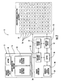
- the charger 14 illustratively includes a base 24 having an area larger than the device conductive footprint 22 and able to receive the portable electronic device 12 thereon in a plurality of different positions.
- the charger 14 may also include and an array of charger capacitive electrodes 26 and a base dielectric layer 25 carried by the base 24.
- the charger 14 further includes, for example, a charger controller 28 for selectively driving the charger capacitive electrodes 26 within the device conductive footprint 22 with a charging signal sufficient to capacitively charge the battery 18 of the portable electronic device 12, and not driving charger capacitive electrodes outside the device conductive footprint with the charging signal when the portable electronic device is positioned on the charger 14 to thereby capacitively charge the battery of the portable electronic device while reducing undesired (EMI).
- EMI undesired
- the charger controller 28 selectively drives the charger capacitive electrodes 26 within the device conductive footprint 22 with a charging signal while not driving the charger capacitive electrodes outside the device conductive footprint.
- the charger capacitive electrodes 26 being driven by the charging signal are covered by the device capacitive electrodes 20, the device capacitive electrodes function as an EMI shield as will be appreciated by those skilled in the art.
- a communication link 38 between the portable electronic device 12 and the computer 30 will be less likely to be disrupted by the operation of charger 14.
- the charger controller 28 may sense impedances, for example, of the charger capacitive electrodes 26 to determine whether a respective charger capacitive electrode is within the device conductive footprint 22 or not. Such sensing permits the charger controller 28 to accommodate the portable electronic device 12 if it is moved across the array of charger capacitive electrodes 26.
- the charger controller 28 may sequentially drive the charger capacitive electrodes 26 with a sensing signal to sense impedances thereof as will be appreciated by those skilled in the art.
- the charging signal may have an amplitude at least one hundred times greater than an amplitude of the sensing signal, for example.
- the control circuit 34 determines which charger capacitive electrodes 26 are within the device conductive footprint 22 by operating the charging signal generator 30 to generate a sensing signal.
- the impedance detector 36 senses a first impedance when a charger capacitive electrode 26 is within the device conductive footprint 22, and senses a second impedance when a charger capacitive electrode 26 is not. This sensing data is communicated to the control circuit 34
- FIG. 5 In addition to the processing device 1800, other parts of the mobile device 1000 are shown schematically in FIG. 5 . These include a communications subsystem 1001; a short-range communications subsystem 1020; the keyboard 1400 and the display 1600, along with other input/output devices 1060, 1080, 1100 and 1120; as well as memory devices 1160,1180 and various other device subsystems 1201.
- the mobile device 1000 is preferably a two-way RF communications device having voice and data communications capabilities.
- the mobile device 1000 preferably has the capability to communicate with other computer systems via the Internet.
Landscapes
- Engineering & Computer Science (AREA)
- Power Engineering (AREA)
- Computer Networks & Wireless Communication (AREA)
- Physics & Mathematics (AREA)
- Electromagnetism (AREA)
- Charge And Discharge Circuits For Batteries Or The Like (AREA)
Abstract
Description
- The invention relates to the field of portable electronic devices, and, more particularly, to portable electronic devices and battery chargers therefore and associated methods.
- Rechargeable batteries are used to power many of today's portable electronic devices. Rechargeable batteries make the portable electronic device more mobile than a device requiring a plug-in power source and this generally adds convenience for the user. However, recharging the batteries for a portable electronic device may be an inconvenience to the user.
- For example, a rechargeable battery may carry a limited charge and therefore a user may have to monitor the charge level. Also, a user may have to make arrangements to provide for the charging of the batteries such as by carrying chargers and/or power cords.
- Compounding these inconveniences for the user is the potential increased power consumption by modem portable electronic devices. Most portable electronic devices provide more functionality than their predecessors, which usually results in increased power consumption. This means more frequent recharging of the batteries of the portable electronic device, which may result in more recharging inconvenience for the user.
- A number of attempts have been made to address recharging for portable electronic devices. For instance,
U.S. Patent No. 6,756,765 to Bruning discloses a system for the contactless recharging of a portable device. The system includes a capacitive plate in a pad onto which the portable device is placed for recharging. - Similarly,
U.S. Patent No. 6,275,681 to Vega et al. discloses a system that includes capacitively coupled capacitor plates for generating an electrostatic field for electrostatic charging of a device like a smart card. The system also includes a charge controller in the rechargeable device for controlling the charging of the battery in the rechargeable device. Another patent to Vega et al. isU.S. Patent No. 6,282,407 , which discloses active and passive electrostatic transceivers that include capacitive charging plates for electrostatically charging. The system also includes an electrostatic reader that continuously generates and transmits an excitation signal to the medium surrounding the reader. In both of the Vega et al. patents, an embodiment is disclosed where a user can manually activate the electrostatic reader instead of having the reader radiating continuously.US 6 803744 discloses an inductive power transfer device for chargin high power cordless appliances. - Unfortunately for some of the above devices, a user may still need to monitor the charge level of the battery in his portable electronic device. In addition, some of the above devices may require the user to precisely align the electrodes of the charging device with the electrodes in the device being charged. Undesired electromagnetic interference (EMI) may also be generated by capacitive charging arrangements.
- In view of the foregoing background, it is therefore an object of the invention to provide an electronic apparatus and method for conveniently charging a portable electronic device battery while reducing undesired electromagnetic interference.
- This and other objects, features, and advantages in accordance with the invention are provided by the invention set out in the independent claims. Some optional features are set out in the claims dependent thereto. In one aspect, there is an electronic apparatus including a portable electronic device and a charger for capacitively charging the portable electronic device when the portable electronic device is temporarily placed adjacent the charger. The portable electronic device may include a housing, a battery carried by the housing, and at least one pair of device capacitive electrodes carried by the housing for charging the battery and defining a device conductive footprint. The charger may include a base having an area larger than the device conductive footprint and which is able to receive the portable electronic device thereon in a plurality of different positions, and an array of charger capacitive electrodes carried by the base. The charger may further include a charger controller for selectively driving the charger capacitive electrodes within the device conductive footprint with a charging signal sufficient to capacitively charge the battery of the portable electronic device. The charger controller may not drive charger capacitive electrodes outside the device conductive footprint with the charging signal when the portable electronic device is positioned on the charger. Accordingly, the charger may conveniently and capacitively charge the battery of the portable electronic device while reducing undesired electromagnetic interference (EMI). This is so since the device capacitive electrodes absorb the energy from the underlying driven charger capacitive electrodes.
- The charger controller may sense impedances of the charger capacitive electrodes to determine whether a respective charger capacitive electrode is within the device conductive footprint or not. The charger controller may sequentially drive the charger capacitive electrodes with a sensing signal to sense impedances thereof. The charging signal may have an amplitude at least one hundred times greater than an amplitude of the sensing signal. This also ensures efficient charging while reducing undesired EMI.
- The charger controller may comprise a charging signal generator, a switching circuit connected between the charging signal generator and the charger capacitive electrodes, and a control circuit connected to the switching circuit. The charger controller may further comprise a buffer connected between the charging signal generator and the switching circuit, and an impedance detector connected to the buffer and the control circuit.
- The control circuit may operate the charging signal generator at a reduced amplitude to serve as a signal generator for the sensing signal. The charger controller and the portable electronic device may also communicate via the charger capacitive electrodes, such as indicate that the battery needs charging or is fully charged.
- A method aspect of the invention is for capacitively charging a portable electronic device with a charger. The portable electronic device may include a housing, a battery carried by the housing, and at least one pair of device capacitive electrodes carried by the housing for charging the battery and defining a device conductive footprint. The charger may include a base having an area larger than the device conductive footprint and able to receive the portable electronic device thereon in a plurality of different positions, an array of charger capacitive electrodes carried by the base, and a charger controller connected to the charger capacitive electrodes. The method may include temporarily placing the portable electronic device adjacent the charger, and selectively driving, via the charger controller, the charger capacitive electrodes within the device conductive footprint with a charging signal sufficient to capacitively charge the battery of the portable electronic device, and not driving charger capacitive electrodes outside the device conductive footprint with the charging signal.
-
FIG. 1 is a schematic perspective view of the electronic apparatus for charging a portable electronic device in a typical work environment according to the invention. -
FIG. 2 is a block diagram of the electronic apparatus as shown inFIG.1 . -
FIG. 3 is a schematic cross-sectional view of the electronic apparatus as shown inFIG. 1 . -
FIG. 4 is a flow chart illustrating a method according to the invention. -
FIG. 5 is a block diagram of a mobile device. - The invention will now be described more fully hereinafter with reference to the accompanying drawings, in which preferred embodiments of the invention are shown. This invention may, however, be embodied in many different forms and should not be construed as limited to the embodiments set forth herein. Rather, these embodiments are provided so that this disclosure will be thorough and complete, and will fully convey the scope of the invention to those skilled in the art. Additionally, like numbers are used to refer to like elements throughout the drawings.
- Referring initially to
FIGS. 1-3 , anelectronic apparatus 10 including a portableelectronic device 12 and acharger 14 for capacitively charging the portable electronic device is now described. The portableelectronic device 12 illustratively includes ahousing 16, abattery 18 carried by the housing, and a pair of devicecapacitive electrodes 20 carried by the housing for charging the battery and defining a deviceconductive footprint 22. Thehousing 16 may further include a housingdielectric layer 17 adjacent the devicecapacitive electrodes 20. The devicecapacitive electrodes 20 are arranged in closely spaced, side-by-side relation. In other embodiments, more than one pair ofdevice electrodes 20 may be provided and/or these electrodes can be arranged in different configurations as will be appreciated by those skilled in the art. - The
charger 14 illustratively includes abase 24 having an area larger than the deviceconductive footprint 22 and able to receive the portableelectronic device 12 thereon in a plurality of different positions. Thecharger 14 may also include and an array of chargercapacitive electrodes 26 and a basedielectric layer 25 carried by thebase 24. Thecharger 14 further includes, for example, acharger controller 28 for selectively driving the chargercapacitive electrodes 26 within the deviceconductive footprint 22 with a charging signal sufficient to capacitively charge thebattery 18 of the portableelectronic device 12, and not driving charger capacitive electrodes outside the device conductive footprint with the charging signal when the portable electronic device is positioned on thecharger 14 to thereby capacitively charge the battery of the portable electronic device while reducing undesired (EMI). - To help control the undesired EMI, the
charger controller 28 selectively drives thecharger capacitive electrodes 26 within the deviceconductive footprint 22 with a charging signal while not driving the charger capacitive electrodes outside the device conductive footprint. In other words, because thecharger capacitive electrodes 26 being driven by the charging signal are covered by thedevice capacitive electrodes 20, the device capacitive electrodes function as an EMI shield as will be appreciated by those skilled in the art. As a result, for example, acommunication link 38 between the portableelectronic device 12 and thecomputer 30 will be less likely to be disrupted by the operation ofcharger 14. - The
charger controller 28 may sense impedances, for example, of thecharger capacitive electrodes 26 to determine whether a respective charger capacitive electrode is within the deviceconductive footprint 22 or not. Such sensing permits thecharger controller 28 to accommodate the portableelectronic device 12 if it is moved across the array ofcharger capacitive electrodes 26. Thecharger controller 28 may sequentially drive thecharger capacitive electrodes 26 with a sensing signal to sense impedances thereof as will be appreciated by those skilled in the art. To further reduce EMI while providing efficient charging, the charging signal may have an amplitude at least one hundred times greater than an amplitude of the sensing signal, for example. - The
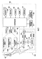
charger controller 28 illustratively comprises acharging signal generator 30, a switchingcircuit 32 connected between the charging signal generator and thecharger capacitive electrodes 26, and acontrol circuit 34 connected to the switching circuit. Thecharger controller 28 further comprises abuffer 36 connected between the chargingsignal generator 30 and the switchingcircuit 32, and animpedance detector 36 connected to the buffer and thecontrol circuit 34. Thecontrol circuit 34 may preferably operate thecharging signal generator 30 at a reduced amplitude to serve as a signal generator for the sensing signal, for example. - The
charger controller 28 and the portableelectronic device 12 can also communicate via thecharger capacitive electrodes 26 such as to indicate the state of charge of thebattery 18. Thecharger 14 is illustratively powered through awall transformer 40. In other embodiments, thecharger 14 can be powered by thecomputer 30 or other devices as will be appreciated by those skilled in the art. - The
control circuit 34 determines whichcharger capacitive electrodes 26 are within the deviceconductive footprint 22 by operating the chargingsignal generator 30 to generate a sensing signal. Theimpedance detector 36 senses a first impedance when acharger capacitive electrode 26 is within the deviceconductive footprint 22, and senses a second impedance when acharger capacitive electrode 26 is not. This sensing data is communicated to thecontrol circuit 34 - The
control circuit 34 uses this data to selectively drive thecharger capacitive electrodes 26 within the deviceconductive footprint 22 with the charging signal, which may be about 1 MHz, for example. The chargingsignal generator 30 generates the charging signal, which is relayed to thebuffer 36. Thebuffer 36 may be a differential buffer, for example, that generates the charging signal to have two components that are substantially 180 degrees out of phase with each other. The switchingcircuit 32 receives the charging signal and selects whichdevice capacitive electrodes 20 receive the charging signal. Thedevice capacitive electrodes 20 capacitively receive the charging signals to a charging circuit within thehousing 16, as will be appreciated by those skilled in the art, and the charging circuit charges thebattery 18. - Referring now additionally to the
flowchart 38 shown inFIG. 4 , a method aspect of the invention is now described. The method is for capacitively charging the portableelectronic device 12 with thecharger 14. The portableelectronic device 12 includes ahousing 16, abattery 18 carried by the housing, and at least one pair ofdevice capacitive electrodes 20 carried by the housing for charging the battery and defining a deviceconductive footprint 22. Thecharger 14 includes a base 24 having an area larger than the deviceconductive footprint 22 and able to receive the portableelectronic device 12 thereon in a plurality of different positions, an array ofcharger capacitive electrodes 26 carried by the base, and acharger controller 28 connected to the charger capacitive electrodes. The method starts atBlock 40 and includes temporarily placing the portableelectronic device 12 adjacent thecharger 14 atBlock 42. Thecharger controller 28 senses the portableelectronic device 12 atBlock 44. The charger controller then selectively drives, atBlock 46, thecharger capacitive electrodes 26 within the deviceconductive footprint 22 with a charging signal sufficient to capacitively charge thebattery 18 of the portableelectronic device 12 and not driving charger capacitive electrodes outside the device conductive footprint with the charging signal to thereby capacitively charge the battery of the portable electronic device while reducing undesired EMI. Thecharger controller 28 continues to sense thecharger capacitive electrodes 26 to monitor the location of the portable electronic device atBlock 48 and the method ends atBlock 50. - An example of the portable
electronic device 12 is a handheld mobilewireless communications device 1000 that may be used in accordance with the invention is further described with reference toFIG. 5 . Thedevice 1000 includes ahousing 1200, akeyboard 1400 and anoutput device 1600. The output device shown is adisplay 1600, which is preferably a full graphic LCD. Other types of output devices may alternatively be utilized. Aprocessing device 1800 is contained within thehousing 1200 and is coupled between thekeyboard 1400 and thedisplay 1600. Theprocessing device 1800 controls the operation of thedisplay 1600, as well as the overall operation of themobile device 1000, in response to actuation of keys on thekeyboard 1400 by the user. - The
housing 1200 may be elongated vertically, or may take on other sizes and shapes (including clamshell housing structures). The keyboard may include a mode selection key, or other hardware or software for switching between text entry and telephony entry. - In addition to the
processing device 1800, other parts of themobile device 1000 are shown schematically inFIG. 5 . These include acommunications subsystem 1001; a short-range communications subsystem 1020; thekeyboard 1400 and thedisplay 1600, along with other input/output devices memory devices other device subsystems 1201. Themobile device 1000 is preferably a two-way RF communications device having voice and data communications capabilities. In addition, themobile device 1000 preferably has the capability to communicate with other computer systems via the Internet. - Operating system software executed by the
processing device 1800 is preferably stored in a persistent store, such as theflash memory 1160, but may be stored in other types of memory devices, such as a read only memory (ROM) or similar storage element. In addition, system software, specific device applications, or parts thereof, may be temporarily loaded into a volatile store, such as the random access memory (RAM) 1180. Communications signals received by the mobile device may also be stored in theRAM 1180. - The
processing device 1800, in addition to its operating system functions, enables execution ofsoftware applications 1300A-1300N on thedevice 1000. A predetermined set of applications that control basic device operations, such as data andvoice communications device 1000 during manufacture. In addition, a personal information manager (PIM) application may be installed during manufacture. The PIM is preferably capable of organizing and managing data items, such as e-mail, calendar events, voice mails, appointments, and task items. The PIM application is also preferably capable of sending and receiving data items via awireless network 1401. Preferably, the PIM data items are seamlessly integrated, synchronized and updated via thewireless network 1401 with the device user's corresponding data items stored or associated with a host computer system. - Communication functions, including data and voice communications, are performed through the
communications subsystem 1001, and possibly through the short-range communications subsystem. Thecommunications subsystem 1001 includes areceiver 1500, atransmitter 1520, and one ormore antennas communications subsystem 1001 also includes a processing module, such as a digital signal processor (DSP) 1580, and local oscillators (LOs) 1601. The specific design and implementation of thecommunications subsystem 1001 is dependent upon the communications network in which themobile device 1000 is intended to operate. For example, amobile device 1000 may include acommunications subsystem 1001 designed to operate with the Mobitex™, Data TAC™ or General Packet Radio Service (GPRS) mobile data communications networks, and also designed to operate with any of a variety of voice communications networks, such as AMPS, TDMA, CDMA, PCS, GSM, etc. Other types of data and voice networks, both separate and integrated, may also be utilized with themobile device 1000. - Network access requirements vary depending upon the type of communication system. For example, in the Mobitex and DataTAC networks, mobile devices are registered on the network using a unique personal identification number or PIN associated with each device. In GPRS networks, however, network access is associated with a subscriber or user of a device. A GPRS device therefore requires a subscriber identity module, commonly referred to as a SIM card, in order to operate on a GPRS network.
- When required network registration or activation procedures have been completed, the
mobile device 1000 may send and receive communications signals over thecommunication network 1401. Signals received from thecommunications network 1401 by theantenna 1540 are routed to thereceiver 1500, which provides for signal amplification, frequency down conversion, filtering, channel selection, etc., and may also provide analog to digital conversion. Analog-to-digital conversion of the received signal allows theDSP 1580 to perform more complex communications functions, such as demodulation and decoding. In a similar manner, signals to be transmitted to thenetwork 1401 are processed (e.g. modulated and encoded) by theDSP 1580 and are then provided to thetransmitter 1520 for digital to analog conversion, frequency up conversion, filtering, amplification and transmission to the communication network 1401 (or networks) via theantenna 1560. - In addition to processing communications signals, the
DSP 1580 provides for control of thereceiver 1500 and thetransmitter 1520. For example, gains applied to communications signals in thereceiver 1500 andtransmitter 1520 may be adaptively controlled through automatic gain control algorithms implemented in theDSP 1580. - In a data communications mode, a received signal, such as a text message or web page download, is processed by the
communications subsystem 1001 and is input to theprocessing device 1800. The received signal is then further processed by theprocessing device 1800 for an output to thedisplay 1600, or alternatively to some other auxiliary I/O device 1060. A device user may also compose data items, such as e-mail messages, using thekeyboard 1400 and/or some other auxiliary I/O device 1060, such as a touchpad, a rocker switch, a thumb-wheel, or some other type of input device. The composed data items may then be transmitted over thecommunications network 1401 via thecommunications subsystem 1001. - In a voice communications mode, overall operation of the device is substantially similar to the data communications mode, except that received signals are output to a
speaker 1100, and signals for transmission are generated by amicrophone 1120. Alternative voice or audio I/O subsystems, such as a voice message recording subsystem, may also be implemented on thedevice 1000. In addition, thedisplay 1600 may also be utilized in voice communications mode, for example to display the identity of a calling party, the duration of a voice call, or other voice call related information. - The short-range communications subsystem enables communication between the
mobile device 1000 and other proximate systems or devices, which need not necessarily be similar devices. For example, the short-range communications subsystem may include an infrared device and associated circuits and components, or a Bluetooth communications module to provide for communication with similarly-enabled systems and devices. - Many modifications and other embodiments of the invention will come to the mind of one skilled in the art having the benefit of the teachings presented in the foregoing descriptions and the associated drawings. Therefore, it is understood that the invention is not to be limited to the specific embodiments disclosed.
Claims (13)
- A charger (14) for capacitively charging a battery (18) in a portable electronic device (12) when the portable electronic device (12) is temporarily placed adjacent the charger (14), the charger (14) comprising:a base (24) having an area larger than the portable electronic device (12) and able to receive the portable electronic device (12) thereon in a plurality of different positions;an array of charging capacitive electrodes (26) carried by said base (24); anda charger controller (28) including
a charging signal generator (30);
a switching circuit (32) connected between said charging signal generator (30) and said charger capacitive electrodes (26);
a control circuit (34) for determining which of the said charger capacitive electrodes (26) are covered by the portable electronic device (12) by operating the charging signal generator (30) to generate a sensing signal;
a buffer connected between said charging signal generator (30) and said switching circuit (32); and
an impedance detector (36) for sensing impedance of said charger capacitive electrodes (26);
wherein said control circuit (34) is connected to said switching circuit (12), and
said impedance detector (36) is connected to the buffer and the control circuit (34), and
said control circuit (34) is adapted to use said sensed impedance by said impedance detector (36) to selectively drive said charger capacitive electrodes (26) covered by the portable electronics device (12) with a charging signal sufficient to capacitively charge the battery (18) of the portable electronic device (12) and not driving charger capacitive electrodes (26) not covered by the portable electronic device (12) with the charging signal when the portable electronic device (12) is positioned on said charger (14). - The charger according to Claim 1 wherein said charger controller (28) sequentially drives said charger capacitive electrodes (26) with a sensing signal to sense impedances thereof.
- The charger according to Claim 1 wherein the charging signal has an amplitude at least one hundred times greater than an amplitude of the sensing signal.
- An electronic apparatus (10) comprising the charger of claim 1, in which;the portable electronic device (12) is capacitively chargeable by the charger (14) when said portable electronic device (17) is temporarily placed adjacent said charger (14),said portable electronic device comprising a housing (16), a battery (18) carried by the housing, and at least one pair of device capacitive electrodes (20) carried by said housing for charging said battery (18) and defining a device conductive footprint (22) and in which:the charger controller (28) is arranged for selectively driving said charger capacitive electrodes (26) within the device conductive footprint with a charging signal sufficient to capacitively charge the battery and not driving charger capacitive electrodes (26) outside the device conductive footprint with the charging signal when said portable electronic device (12) is positioned on said charger (14) to thereby capacitively charge said battery (18) of said portable electronic device (12) while reducing undesired electromagnetic interference (EMI).
- The electronic apparatus according to Claim 4 wherein said charger controller (28) senses impedances of said charger capacitive electrodes (26) to determine whether a respective charger capacitive electrode (26) is within the device conductive footprint or not.
- The electronic apparatus according to Claim 5 wherein said charger controller (28) sequentially drives said charger capacitive electrodes (26) with a sensing signal to sense impedances thereof.
- The electronic apparatus according to Claim 6 wherein the charging signal has an amplitude at least one hundred times greater than an amplitude of the sensing signal.
- The electronic apparatus according to Claim 4 wherein said control circuit operates said charging signal generator (30) at a reduced amplitude to serve as a signal generator for the sensing signal.
- The electronic apparatus according to Claim 4 wherein said charger controller (28) and said portable electronic device (12) also communicate via said charger capacitive electrodes (26).
- A method of capacitively charging a portable electronic device with a charger, the portable electronic device comprising a housing, a battery carried by the housing, and at least one pair of device capacitive electrodes carried by the housing for charging the battery and defining a device conductive footprint, and the charger comprising a base having an area larger than the device conductive footprint and able to receive the portable electronic device thereon in a plurality of different positions, an array of charger capacitive electrodes carried by the base, and a charger controller connected to the charger capacitive electrodes, the charger controller including a charging signal generator, a switching circuit connected between the charging signal generator and the charger capacitive electrodes, a control circuit connected to the switching circuit, a buffer connected between the charging signal generator and the switching circuit, and an impedance detector connected to the buffer and the control circuit, the method comprising:temporarily placing the portable electronic device adjacent the charger; andselectively driving, via the charger controller, the charger capacitive electrodes within the device conductive footprint with a charging signal sufficient to capacitively charge the battery of the portable electronic device and not driving charger capacitive electrodes outside the device conductive footprint with the charging signal to thereby capacitively charge the battery of the portable electronic device while reducing undesired electromagnetic interference (EMI).
- The method according to Claim 10 further comprising sensing, via the charger controller, the impedances of the charger capacitive electrodes to determine whether a respective charger capacitive electrode is within the device conductive footprint or not.
- The method according to Claim 11 further comprising sequentially driving, via the charger controller, the charger capacitive electrodes with a sensing signal to sense impedances thereof.
- The method according to Claim 12 wherein the charging signal has an amplitude at least one hundred times greater than an amplitude of the sensing signal.
Priority Applications (5)
| Application Number | Priority Date | Filing Date | Title |
|---|---|---|---|
| DE602005013635T DE602005013635D1 (en) | 2005-02-04 | 2005-02-04 | Device and method for charging a battery via capacitive coupling |
| US11/051,581 US7504802B2 (en) | 2005-02-04 | 2005-02-04 | Portable electronic device and capacitive charger therefor and associated methods |
| EP05250617A EP1689062B1 (en) | 2005-02-04 | 2005-02-04 | Apparatus and method for charging a battery through capacitive coupling |
| AT05250617T ATE427576T1 (en) | 2005-02-04 | 2005-02-04 | DEVICE AND METHOD FOR CHARGING A BATTERY VIA CAPACITIVE COUPLING |
| CA002526245A CA2526245C (en) | 2005-02-04 | 2005-12-06 | Portable electronic device and capacitive charger therefor and associated methods |
Applications Claiming Priority (1)
| Application Number | Priority Date | Filing Date | Title |
|---|---|---|---|
| EP05250617A EP1689062B1 (en) | 2005-02-04 | 2005-02-04 | Apparatus and method for charging a battery through capacitive coupling |
Publications (2)
| Publication Number | Publication Date |
|---|---|
| EP1689062A1 EP1689062A1 (en) | 2006-08-09 |
| EP1689062B1 true EP1689062B1 (en) | 2009-04-01 |
Family
ID=34940429
Family Applications (1)
| Application Number | Title | Priority Date | Filing Date |
|---|---|---|---|
| EP05250617A Active EP1689062B1 (en) | 2005-02-04 | 2005-02-04 | Apparatus and method for charging a battery through capacitive coupling |
Country Status (5)
| Country | Link |
|---|---|
| US (1) | US7504802B2 (en) |
| EP (1) | EP1689062B1 (en) |
| AT (1) | ATE427576T1 (en) |
| CA (1) | CA2526245C (en) |
| DE (1) | DE602005013635D1 (en) |
Cited By (2)
| Publication number | Priority date | Publication date | Assignee | Title |
|---|---|---|---|---|
| DE102010015510A1 (en) * | 2010-04-20 | 2011-10-20 | Gira Giersiepen Gmbh & Co. Kg | System comprising a mobile unit and a device for contactless charging of the mobile unit with electrical energy |
| JP2012095505A (en) * | 2010-10-29 | 2012-05-17 | Murata Mfg Co Ltd | Wireless power transmission system and power transmitter |
Families Citing this family (25)
| Publication number | Priority date | Publication date | Assignee | Title |
|---|---|---|---|---|
| US20090072782A1 (en) * | 2002-12-10 | 2009-03-19 | Mitch Randall | Versatile apparatus and method for electronic devices |
| JP4318044B2 (en) | 2005-03-03 | 2009-08-19 | ソニー株式会社 | Power supply system, power supply apparatus and method, power reception apparatus and method, recording medium, and program |
| KR100792308B1 (en) * | 2006-01-31 | 2008-01-07 | 엘에스전선 주식회사 | A contact-less power supply, contact-less charger systems and method for charging rechargeable battery cell |
| US7772802B2 (en) | 2007-03-01 | 2010-08-10 | Eastman Kodak Company | Charging display system |
| FR2920061A1 (en) * | 2007-08-17 | 2009-02-20 | Patrick Camurati | METHOD AND DEVICE FOR TRANSPORTING, DISTRIBUTING AND MANAGING ELECTRICAL ENERGY BY LONGITUDINAL COUPLING IN A CLOSE FIELD BETWEEN ELECTRIC DIPOLES |
| WO2009041058A1 (en) * | 2007-09-27 | 2009-04-02 | Panasonic Corporation | Electronic device, recharger and recharging system |
| JP4557049B2 (en) * | 2008-06-09 | 2010-10-06 | ソニー株式会社 | Transmission system, power supply apparatus, power reception apparatus, and transmission method |
| US8626249B2 (en) * | 2008-08-12 | 2014-01-07 | T-Mobile Usa, Inc. | Charging station that operates as an intermediary device between mobile devices and other devices |
| KR101510760B1 (en) * | 2009-01-19 | 2015-04-10 | 삼성전자 주식회사 | Display apparatus and control method thereof |
| KR101782083B1 (en) * | 2010-09-08 | 2017-09-27 | 삼성전자주식회사 | Roof type charging apparatus using resonant power transmission |
| JP5605153B2 (en) | 2010-10-15 | 2014-10-15 | ソニー株式会社 | Power supply device, power supply method, and power supply system |
| JP5772501B2 (en) * | 2011-10-25 | 2015-09-02 | 株式会社村田製作所 | Power transmission system |
| JP5839105B2 (en) | 2012-02-22 | 2016-01-06 | 株式会社村田製作所 | Power transmission device and power transmission control method |
| US10149711B2 (en) | 2012-03-30 | 2018-12-11 | Depuy Mitek, Llc | Surgical impact tool |
| KR101901720B1 (en) * | 2012-04-02 | 2018-11-13 | 삼성전자주식회사 | Method for interworing with dummy device and an electronic device thereof |
| US20140021798A1 (en) * | 2012-07-17 | 2014-01-23 | Witricity Corporation | Wireless energy transfer with repeater resonators |
| JP6170057B2 (en) * | 2012-09-25 | 2017-07-26 | 富士機械製造株式会社 | Electrostatic coupling type non-contact power feeding device and control method thereof |
| EP2903131B1 (en) * | 2012-09-26 | 2022-03-02 | FUJI Corporation | Electrostatic-coupling-type non-contact power supply apparatus |
| EP2903132B1 (en) * | 2012-09-28 | 2017-05-31 | Fuji Machine Mfg. Co., Ltd. | Capacitive-coupling-system non-contacting power-feed apparatus |
| US20140197782A1 (en) * | 2013-01-15 | 2014-07-17 | Lite-On It Corporation | Wireless charger with combined electric radiation shielding and capacitive sensing functions |
| JP6127777B2 (en) * | 2013-06-28 | 2017-05-17 | ソニー株式会社 | Power supply device and power supply system |
| US10050463B2 (en) * | 2013-08-15 | 2018-08-14 | Humavox Ltd. | Wireless charging device |
| US10014705B2 (en) | 2015-04-02 | 2018-07-03 | Apple Inc. | Signal quality dependent throttling of devices for reducing electromagnetic interference |
| US10283952B2 (en) | 2017-06-22 | 2019-05-07 | Bretford Manufacturing, Inc. | Rapidly deployable floor power system |
| US11456623B2 (en) | 2020-11-04 | 2022-09-27 | Lagree Technologies, Inc. | Wireless power system for an exercise machine |
Family Cites Families (30)
| Publication number | Priority date | Publication date | Assignee | Title |
|---|---|---|---|---|
| US31118A (en) * | 1861-01-15 | Improvement in seeding-cultivators | ||
| GB8625429D0 (en) * | 1986-10-23 | 1986-11-26 | Philp R | Contactless electronic connectors |
| US4688097A (en) * | 1986-10-30 | 1987-08-18 | Jerrold Electronics Corp. | D.C.-coupled video clamping circuit |
| DE3906349A1 (en) | 1989-03-01 | 1990-09-13 | Hartmut Hennige | METHOD AND DEVICE FOR SIMPLIFYING THE USE OF A VARIETY OF CREDIT CARDS AND THE LIKE |
| US5519262A (en) | 1992-11-17 | 1996-05-21 | Wood; Mark B. | Near field power coupling system |
| US5525843A (en) * | 1994-02-14 | 1996-06-11 | Ab Volvo | Seat occupant detection system |
| JP2671809B2 (en) * | 1994-06-30 | 1997-11-05 | 日本電気株式会社 | Non-contact charging device |
| DE19519881C1 (en) | 1995-05-31 | 1996-07-18 | Grundig Emv | Battery charging device for cordless telephone |
| US6067368A (en) | 1996-01-26 | 2000-05-23 | Authentec, Inc. | Fingerprint sensor having filtering and power conserving features and related methods |
| US5682032A (en) | 1996-02-22 | 1997-10-28 | Philipp; Harald | Capacitively coupled identity verification and escort memory apparatus |
| US5847447A (en) | 1996-07-09 | 1998-12-08 | Ambient Corporation | Capcitively coupled bi-directional data and power transmission system |
| JPH1092673A (en) | 1996-07-26 | 1998-04-10 | Tdk Corp | Non-contact power transmission device |
| US6331744B1 (en) | 1998-02-10 | 2001-12-18 | Light Sciences Corporation | Contactless energy transfer apparatus |
| US6173899B1 (en) | 1998-04-03 | 2001-01-16 | Alexander Rozin | Method and system for contactless energy transmission and data exchange between a terminal and IC card |
| US6275681B1 (en) | 1998-04-16 | 2001-08-14 | Motorola, Inc. | Wireless electrostatic charging and communicating system |
| US6282407B1 (en) | 1998-04-16 | 2001-08-28 | Motorola, Inc. | Active electrostatic transceiver and communicating system |
| US6380711B2 (en) | 1999-06-30 | 2002-04-30 | Research In Motion Limited | Battery recharging device and method and an automatic battery detection system and method therefor |
| US6803744B1 (en) * | 1999-11-01 | 2004-10-12 | Anthony Sabo | Alignment independent and self aligning inductive power transfer system |
| DE20004691U1 (en) | 2000-03-14 | 2000-06-29 | Yang Wen Chin | Charging device with USB interface for a GSM telephone battery |
| US6184651B1 (en) | 2000-03-20 | 2001-02-06 | Motorola, Inc. | Contactless battery charger with wireless control link |
| DE10026173A1 (en) | 2000-04-18 | 2001-10-31 | Schleifring Und Appbau Gmbh | Arrangement for transferring electrical energy/signals has voltage-isolated primary circuit at each central unit connection point, external unit secondary circuits |
| JP2004511191A (en) | 2000-04-18 | 2004-04-08 | シュライフリング ウント アパラーテバウ ゲゼルシャフト ミット ベシュレンクテル ハフツング | Devices for transmitting electrical energy or signals |
| JP4188680B2 (en) | 2000-05-26 | 2008-11-26 | オートモーティブ システムズ ラボラトリー インコーポレーテッド | Occupant sensor |
| TW479393B (en) | 2000-09-27 | 2002-03-11 | Acer Peripherals Inc | Automatic USB charging apparatus and its operating method |
| US6362610B1 (en) | 2001-08-14 | 2002-03-26 | Fu-I Yang | Universal USB power supply unit |
| GB0213374D0 (en) * | 2002-06-10 | 2002-07-24 | Univ City Hong Kong | Planar inductive battery charger |
| US6614206B1 (en) | 2002-05-23 | 2003-09-02 | Palm, Inc. | Universal USB charging accessory |
| JP3905005B2 (en) * | 2002-09-18 | 2007-04-18 | 富士通株式会社 | Portable device and semiconductor integrated circuit device |
| US6756765B2 (en) | 2002-10-08 | 2004-06-29 | Koninklijke Philips Electronics N.V. | System and method for charging users to recharge power supplies in portable devices |
| US7570994B2 (en) | 2003-04-25 | 2009-08-04 | Medtronic Physio-Control Corp. | Apparatus and method for maintaining a defibrillator battery charge and optionally communicating |
-
2005
- 2005-02-04 EP EP05250617A patent/EP1689062B1/en active Active
- 2005-02-04 AT AT05250617T patent/ATE427576T1/en not_active IP Right Cessation
- 2005-02-04 US US11/051,581 patent/US7504802B2/en active Active
- 2005-02-04 DE DE602005013635T patent/DE602005013635D1/en active Active
- 2005-12-06 CA CA002526245A patent/CA2526245C/en active Active
Cited By (3)
| Publication number | Priority date | Publication date | Assignee | Title |
|---|---|---|---|---|
| DE102010015510A1 (en) * | 2010-04-20 | 2011-10-20 | Gira Giersiepen Gmbh & Co. Kg | System comprising a mobile unit and a device for contactless charging of the mobile unit with electrical energy |
| EP2381558A2 (en) | 2010-04-20 | 2011-10-26 | GIRA GIERSIEPEN GmbH & Co. KG | System comprising a mobile unit and a device for contactless charging of the mobile unit with electrical energy |
| JP2012095505A (en) * | 2010-10-29 | 2012-05-17 | Murata Mfg Co Ltd | Wireless power transmission system and power transmitter |
Also Published As
| Publication number | Publication date |
|---|---|
| EP1689062A1 (en) | 2006-08-09 |
| US7504802B2 (en) | 2009-03-17 |
| DE602005013635D1 (en) | 2009-05-14 |
| US20060176015A1 (en) | 2006-08-10 |
| ATE427576T1 (en) | 2009-04-15 |
| CA2526245A1 (en) | 2006-02-20 |
| CA2526245C (en) | 2006-11-28 |
Similar Documents
| Publication | Publication Date | Title |
|---|---|---|
| EP1689062B1 (en) | Apparatus and method for charging a battery through capacitive coupling | |
| US7511452B2 (en) | Portable electronic device and capacitive charger providing data transfer and associated methods | |
| US7791311B2 (en) | Apparatus and method of wirelessly sharing power by inductive method | |
| CN104953626B (en) | Wireless power in local calculation environment uses | |
| KR102012972B1 (en) | Apparatus for transmitting and receiving wireless power | |
| US8368515B2 (en) | Dual mode RFID communication device operating as a reader or tag | |
| EP1834394B1 (en) | Method and apparatus for near field communications | |
| US20100038970A1 (en) | Short Range Efficient Wireless Power Transfer | |
| JP2003070187A (en) | Non-contacting data carrier device and method for charging built-in secondary battery | |
| CN101447684A (en) | Wirelss charging system | |
| EP2568531B1 (en) | Mobile wireless communications device including acoustic coupling based impedance adjustment and related methods | |
| KR101796788B1 (en) | Apparatus and method for trasmitting energy | |
| EP2579423B1 (en) | Wireless charging and communication with power source devices and power charge devices in a communication system | |
| US20210226668A1 (en) | Antenna activation method for a near-field communication device | |
| KR20100019208A (en) | Charge apparatus for using radio frequency | |
| CN111613762B (en) | Battery pack, electronic device, and charge/discharge control method | |
| KR20150028397A (en) | Wireless power transfer method inside vehicle using NFC | |
| EP2546997A1 (en) | Mobile wireless communications device to authenticate a removable power source via NFC communications and associated methods | |
| JP5749533B2 (en) | Electronics | |
| KR20170122906A (en) | The method of impedance matching at the wireless power transfer based on magnetic resonance coupling and Apparatus therefor | |
| KR20090072413A (en) | Contactless power suppy system |
Legal Events
| Date | Code | Title | Description |
|---|---|---|---|
| PUAI | Public reference made under article 153(3) epc to a published international application that has entered the european phase |
Free format text: ORIGINAL CODE: 0009012 |
|
| 17P | Request for examination filed |
Effective date: 20050215 |
|
| AK | Designated contracting states |
Kind code of ref document: A1 Designated state(s): AT BE BG CH CY CZ DE DK EE ES FI FR GB GR HU IE IS IT LI LT LU MC NL PL PT RO SE SI SK TR |
|
| AX | Request for extension of the european patent |
Extension state: AL BA HR LV MK YU |
|
| 17Q | First examination report despatched |
Effective date: 20070221 |
|
| AKX | Designation fees paid |
Designated state(s): AT BE BG CH CY CZ DE DK EE ES FI FR GB GR HU IE IS IT LI LT LU MC NL PL PT RO SE SI SK TR |
|
| AXX | Extension fees paid |
Extension state: YU Payment date: 20070122 Extension state: BA Payment date: 20070122 Extension state: AL Payment date: 20070122 Extension state: MK Payment date: 20070122 Extension state: HR Payment date: 20070122 Extension state: LV Payment date: 20070122 |
|
| GRAP | Despatch of communication of intention to grant a patent |
Free format text: ORIGINAL CODE: EPIDOSNIGR1 |
|
| GRAS | Grant fee paid |
Free format text: ORIGINAL CODE: EPIDOSNIGR3 |
|
| GRAA | (expected) grant |
Free format text: ORIGINAL CODE: 0009210 |
|
| AK | Designated contracting states |
Kind code of ref document: B1 Designated state(s): AT BE BG CH CY CZ DE DK EE ES FI FR GB GR HU IE IS IT LI LT LU MC NL PL PT RO SE SI SK TR |
|
| AX | Request for extension of the european patent |
Extension state: AL BA HR LV MK YU |
|
| REG | Reference to a national code |
Ref country code: GB Ref legal event code: FG4D |
|
| REG | Reference to a national code |
Ref country code: CH Ref legal event code: EP |
|
| REG | Reference to a national code |
Ref country code: IE Ref legal event code: FG4D |
|
| REF | Corresponds to: |
Ref document number: 602005013635 Country of ref document: DE Date of ref document: 20090514 Kind code of ref document: P |
|
| PG25 | Lapsed in a contracting state [announced via postgrant information from national office to epo] |
Ref country code: SI Free format text: LAPSE BECAUSE OF FAILURE TO SUBMIT A TRANSLATION OF THE DESCRIPTION OR TO PAY THE FEE WITHIN THE PRESCRIBED TIME-LIMIT Effective date: 20090401 |
|
| NLV1 | Nl: lapsed or annulled due to failure to fulfill the requirements of art. 29p and 29m of the patents act | ||
| PG25 | Lapsed in a contracting state [announced via postgrant information from national office to epo] |
Ref country code: FI Free format text: LAPSE BECAUSE OF FAILURE TO SUBMIT A TRANSLATION OF THE DESCRIPTION OR TO PAY THE FEE WITHIN THE PRESCRIBED TIME-LIMIT Effective date: 20090401 Ref country code: ES Free format text: LAPSE BECAUSE OF FAILURE TO SUBMIT A TRANSLATION OF THE DESCRIPTION OR TO PAY THE FEE WITHIN THE PRESCRIBED TIME-LIMIT Effective date: 20090712 Ref country code: EE Free format text: LAPSE BECAUSE OF FAILURE TO SUBMIT A TRANSLATION OF THE DESCRIPTION OR TO PAY THE FEE WITHIN THE PRESCRIBED TIME-LIMIT Effective date: 20090401 Ref country code: LT Free format text: LAPSE BECAUSE OF FAILURE TO SUBMIT A TRANSLATION OF THE DESCRIPTION OR TO PAY THE FEE WITHIN THE PRESCRIBED TIME-LIMIT Effective date: 20090401 Ref country code: AT Free format text: LAPSE BECAUSE OF FAILURE TO SUBMIT A TRANSLATION OF THE DESCRIPTION OR TO PAY THE FEE WITHIN THE PRESCRIBED TIME-LIMIT Effective date: 20090401 Ref country code: PT Free format text: LAPSE BECAUSE OF FAILURE TO SUBMIT A TRANSLATION OF THE DESCRIPTION OR TO PAY THE FEE WITHIN THE PRESCRIBED TIME-LIMIT Effective date: 20090902 |
|
| PG25 | Lapsed in a contracting state [announced via postgrant information from national office to epo] |
Ref country code: SE Free format text: LAPSE BECAUSE OF FAILURE TO SUBMIT A TRANSLATION OF THE DESCRIPTION OR TO PAY THE FEE WITHIN THE PRESCRIBED TIME-LIMIT Effective date: 20090701 Ref country code: NL Free format text: LAPSE BECAUSE OF FAILURE TO SUBMIT A TRANSLATION OF THE DESCRIPTION OR TO PAY THE FEE WITHIN THE PRESCRIBED TIME-LIMIT Effective date: 20090401 Ref country code: IS Free format text: LAPSE BECAUSE OF FAILURE TO SUBMIT A TRANSLATION OF THE DESCRIPTION OR TO PAY THE FEE WITHIN THE PRESCRIBED TIME-LIMIT Effective date: 20090801 Ref country code: PL Free format text: LAPSE BECAUSE OF FAILURE TO SUBMIT A TRANSLATION OF THE DESCRIPTION OR TO PAY THE FEE WITHIN THE PRESCRIBED TIME-LIMIT Effective date: 20090401 |
|
| PG25 | Lapsed in a contracting state [announced via postgrant information from national office to epo] |
Ref country code: CZ Free format text: LAPSE BECAUSE OF FAILURE TO SUBMIT A TRANSLATION OF THE DESCRIPTION OR TO PAY THE FEE WITHIN THE PRESCRIBED TIME-LIMIT Effective date: 20090401 Ref country code: DK Free format text: LAPSE BECAUSE OF FAILURE TO SUBMIT A TRANSLATION OF THE DESCRIPTION OR TO PAY THE FEE WITHIN THE PRESCRIBED TIME-LIMIT Effective date: 20090401 Ref country code: RO Free format text: LAPSE BECAUSE OF FAILURE TO SUBMIT A TRANSLATION OF THE DESCRIPTION OR TO PAY THE FEE WITHIN THE PRESCRIBED TIME-LIMIT Effective date: 20090401 |
|
| PLBE | No opposition filed within time limit |
Free format text: ORIGINAL CODE: 0009261 |
|
| STAA | Information on the status of an ep patent application or granted ep patent |
Free format text: STATUS: NO OPPOSITION FILED WITHIN TIME LIMIT |
|
| PG25 | Lapsed in a contracting state [announced via postgrant information from national office to epo] |
Ref country code: BE Free format text: LAPSE BECAUSE OF FAILURE TO SUBMIT A TRANSLATION OF THE DESCRIPTION OR TO PAY THE FEE WITHIN THE PRESCRIBED TIME-LIMIT Effective date: 20090401 Ref country code: SK Free format text: LAPSE BECAUSE OF FAILURE TO SUBMIT A TRANSLATION OF THE DESCRIPTION OR TO PAY THE FEE WITHIN THE PRESCRIBED TIME-LIMIT Effective date: 20090401 |
|
| 26N | No opposition filed |
Effective date: 20100105 |
|
| PG25 | Lapsed in a contracting state [announced via postgrant information from national office to epo] |
Ref country code: BG Free format text: LAPSE BECAUSE OF FAILURE TO SUBMIT A TRANSLATION OF THE DESCRIPTION OR TO PAY THE FEE WITHIN THE PRESCRIBED TIME-LIMIT Effective date: 20090701 |
|
| REG | Reference to a national code |
Ref country code: CH Ref legal event code: PL |
|
| PG25 | Lapsed in a contracting state [announced via postgrant information from national office to epo] |
Ref country code: GR Free format text: LAPSE BECAUSE OF FAILURE TO SUBMIT A TRANSLATION OF THE DESCRIPTION OR TO PAY THE FEE WITHIN THE PRESCRIBED TIME-LIMIT Effective date: 20090702 Ref country code: CH Free format text: LAPSE BECAUSE OF NON-PAYMENT OF DUE FEES Effective date: 20100228 Ref country code: LI Free format text: LAPSE BECAUSE OF NON-PAYMENT OF DUE FEES Effective date: 20100228 Ref country code: MC Free format text: LAPSE BECAUSE OF NON-PAYMENT OF DUE FEES Effective date: 20100301 |
|
| PG25 | Lapsed in a contracting state [announced via postgrant information from national office to epo] |
Ref country code: IE Free format text: LAPSE BECAUSE OF NON-PAYMENT OF DUE FEES Effective date: 20100204 |
|
| PG25 | Lapsed in a contracting state [announced via postgrant information from national office to epo] |
Ref country code: IT Free format text: LAPSE BECAUSE OF FAILURE TO SUBMIT A TRANSLATION OF THE DESCRIPTION OR TO PAY THE FEE WITHIN THE PRESCRIBED TIME-LIMIT Effective date: 20090401 |
|
| PG25 | Lapsed in a contracting state [announced via postgrant information from national office to epo] |
Ref country code: CY Free format text: LAPSE BECAUSE OF FAILURE TO SUBMIT A TRANSLATION OF THE DESCRIPTION OR TO PAY THE FEE WITHIN THE PRESCRIBED TIME-LIMIT Effective date: 20090401 |
|
| PG25 | Lapsed in a contracting state [announced via postgrant information from national office to epo] |
Ref country code: LU Free format text: LAPSE BECAUSE OF NON-PAYMENT OF DUE FEES Effective date: 20100204 Ref country code: HU Free format text: LAPSE BECAUSE OF FAILURE TO SUBMIT A TRANSLATION OF THE DESCRIPTION OR TO PAY THE FEE WITHIN THE PRESCRIBED TIME-LIMIT Effective date: 20091002 |
|
| PG25 | Lapsed in a contracting state [announced via postgrant information from national office to epo] |
Ref country code: TR Free format text: LAPSE BECAUSE OF FAILURE TO SUBMIT A TRANSLATION OF THE DESCRIPTION OR TO PAY THE FEE WITHIN THE PRESCRIBED TIME-LIMIT Effective date: 20090401 |
|
| REG | Reference to a national code |
Ref country code: DE Ref legal event code: R082 Ref document number: 602005013635 Country of ref document: DE Representative=s name: MERH-IP MATIAS ERNY REICHL HOFFMANN, DE |
|
| REG | Reference to a national code |
Ref country code: DE Ref legal event code: R082 Ref document number: 602005013635 Country of ref document: DE Representative=s name: MERH-IP MATIAS ERNY REICHL HOFFMANN, DE Effective date: 20140925 Ref country code: DE Ref legal event code: R081 Ref document number: 602005013635 Country of ref document: DE Owner name: BLACKBERRY LIMITED, WATERLOO, CA Free format text: FORMER OWNER: RESEARCH IN MOTION LTD., WATERLOO, ONTARIO, CA Effective date: 20140925 Ref country code: DE Ref legal event code: R082 Ref document number: 602005013635 Country of ref document: DE Representative=s name: MERH-IP MATIAS ERNY REICHL HOFFMANN PATENTANWA, DE Effective date: 20140925 |
|
| REG | Reference to a national code |
Ref country code: FR Ref legal event code: PLFP Year of fee payment: 12 |
|
| REG | Reference to a national code |
Ref country code: FR Ref legal event code: PLFP Year of fee payment: 13 |
|
| REG | Reference to a national code |
Ref country code: FR Ref legal event code: PLFP Year of fee payment: 14 |
|
| PGFP | Annual fee paid to national office [announced via postgrant information from national office to epo] |
Ref country code: FR Payment date: 20230223 Year of fee payment: 19 |
|
| PGFP | Annual fee paid to national office [announced via postgrant information from national office to epo] |
Ref country code: GB Payment date: 20230227 Year of fee payment: 19 Ref country code: DE Payment date: 20230223 Year of fee payment: 19 |