EP1683720A2 - Multi-mode searchlight - Google Patents
Multi-mode searchlight Download PDFInfo
- Publication number
- EP1683720A2 EP1683720A2 EP06112696A EP06112696A EP1683720A2 EP 1683720 A2 EP1683720 A2 EP 1683720A2 EP 06112696 A EP06112696 A EP 06112696A EP 06112696 A EP06112696 A EP 06112696A EP 1683720 A2 EP1683720 A2 EP 1683720A2
- Authority
- EP
- European Patent Office
- Prior art keywords
- housing
- sector
- lighthead
- visible light
- infrared
- Prior art date
- Legal status (The legal status is an assumption and is not a legal conclusion. Google has not performed a legal analysis and makes no representation as to the accuracy of the status listed.)
- Granted
Links
Images


Classifications
-
- B—PERFORMING OPERATIONS; TRANSPORTING
- B64—AIRCRAFT; AVIATION; COSMONAUTICS
- B64D—EQUIPMENT FOR FITTING IN OR TO AIRCRAFT; FLIGHT SUITS; PARACHUTES; ARRANGEMENTS OR MOUNTING OF POWER PLANTS OR PROPULSION TRANSMISSIONS IN AIRCRAFT
- B64D47/00—Equipment not otherwise provided for
- B64D47/02—Arrangements or adaptations of signal or lighting devices
-
- B—PERFORMING OPERATIONS; TRANSPORTING
- B64—AIRCRAFT; AVIATION; COSMONAUTICS
- B64D—EQUIPMENT FOR FITTING IN OR TO AIRCRAFT; FLIGHT SUITS; PARACHUTES; ARRANGEMENTS OR MOUNTING OF POWER PLANTS OR PROPULSION TRANSMISSIONS IN AIRCRAFT
- B64D2203/00—Aircraft or airfield lights using LEDs
Definitions
- a multi-mode lighthead system comprising a lighthead housing having front, rear, top, and bottom sectors; an imaging module positioned within the housing to capture an image from the front sector of the housing; a display for viewing and retaining the image from the imaging module; a positioning and control system for positioning and controlling the lighthead housing; an attachment portion connected with at least one of the sectors of the housing and interfacing with the positioning and control system; at least one high intensity infrared diode, the diode being installed into the housing from the rear sector of the housing and positioned to emit infrared light from the front sector of the housing; and at least one visible light source, the visible light source being installed within the housing from the rear sector of the housing such that the visible light source emits light from the front sector of the housing.
- FIG. 1 is a side view of a helicopter equipped with a multi-mode lighthead according to the present invention
- logic circuit 410 detects the presence of an electrical voltage on the "NVIS" logic line 422, the driver control 414 activates the driver 408.
- the driver 408, such as an electrical current limiter, supplies a controlled amount of electrical current to the infrared light sources 302, thereby causing the infrared light sources 302 to emit infrared light.
- the logic circuit 410 turns off both the visible light sources 200 and the infrared light sources 302 when no voltage is detected on either of the logic lines 420, 422.
- the logic circuit 410 also turns off both the visible light sources 200 and the infrared light sources 302 if an illegal logic condition exists, e.g., such as voltage present on both logic lines 420, 422.
- FIG. 12 is a schematic view of an exemplary wiring diagram for a multi-mode lighthead of the present invention having visible light, infrared light and/or infrared laser designator capabilities.
- the wiring diagram shown is directed toward a multi-mode lighthead system in which the IR laser 400 is mounted exterior to the housing of the canopy 2, e.g., the IR laser 400 is mounted in the vicinity of the canopy 2 with the use of an optical slip ring as described above.
- FIG. 14 is a block diagram of a multi-mode lighthead of the present invention incorporating fixed-target tracking searchlight capability.
- the fixed target tracking searchlight utilizes a searchlight controller 500 for processing feedback coordinates from a tracking system, e.g., data such as that shown in FIG. 13.
- a searchlight controller 500 for processing feedback coordinates from a tracking system, e.g., data such as that shown in FIG. 13.
- the searchlight controller can be utilized with modification or duplicated to support additional functions such as the imaging module 1, infrared module 302, etc.
- a first and second power driver circuit motor, a right/left motor, an extend/retract motor, respective gear assemblies with speed and torque scaling and an output shaft for controlling the absolute position sensing of the searchlight is provided and controlled via the searchlight controller 500.
Abstract
- a housing (102) having front, rear, top, and bottom sectors;
- a high power infrared laser (400) within the housing (102);
- a laser (400) aperture opening at the front sector (122) of the housing (102);
- at least one high intensity infrared diode (302), said diode being installed into said housing (102) from the rear sector (128) of said housing (102) and positioned to emit infrared light from the front sector (122) of said housing (102); and
- at least one visible light source (200), said visible light source (200) being installed within said housing (102) from the rear sector (128) of said housing (102) such that said visible light source (200) emits light from the front sector (122) of said housing (102).
Description
- The present invention is generally directed to a multi-mode searchlight, and more particularly to a multi-mode searchlight providing infrared, conventional, and/or other miscellaneous visual aids for an operator of a helicopter. Specifically, the present invention relates to a multi-mode visible and infrared lighthead for use with aircraft landing lights and searchlights, and for use with other vehicles and systems.
- The following discussion of the background art is a result of the present inventors analysis of the systems and features of searchlight technology of the background art. The present invention relates to limitations on a flight crew's ability to see areas outside the aircraft, such as areas that are blocked by the aircraft's structure. Aircraft generally have landing lights mounted thereon to provide illumination during taxi, take-off, and landing when visibility is reduced by darkness or adverse weather conditions.
- Landing lights may be mounted in a fixed position on the aircraft. Alternatively, the landing lights may be pivotable by a drive unit or device to extend from the aircraft when needed, and retracted to reduce drag when not in use. Searchlights are pivotable by a drive device similar to landing lights, but include an additional capability to rotate up to 360 degrees in a plane perpendicular to the extend-retract plane. Military and law enforcement helicopters commonly use searchlights to aim a beam of light in a desired direction to illuminate targets.
- With the advent of infrared based Night Vision Imaging Systems ("NVIS") for covert operations, a need has arisen for landing lights and searchlights that are compatible with NVIS by producing infrared light for illuminating the selected landing and search areas while eliminating visible light. Early NVIS-compatible landing and searchlights used infrared light filters installed over conventional visible lighting systems.
- A disadvantage of early NVIS-compatible lighting systems was that the flight crew could not switch from visible to NVIS modes during a mission, since the infrared filters were required to be installed and removed while the aircraft was on the ground. This disadvantage was overcome by prior dual mode lightheads containing both visible and infrared lighting elements.
- U.S. Patent No. 5,695,272 to Snyder et al., the entirety of which is hereby incorporated by reference, describes an exemplary visible and infrared lighting element of the background art. Snyder et al. describes a lamp head having a visible light section and an infrared section. An operator is able to switch between infrared and visible light filaments controlled on a lamp head that may be extended, retracted and rotated through the use of relays and a mode selector switch.
- Dual mode lightheads allow the flight crew to switch between visible and infrared lighting modes by simply applying electrical power to either the infrared or visible portions of the dual mode lighthead as desired. While prior dual mode lightheads offer significant advantages over early manually-installed filters, they suffer from several disadvantages. First, replacement of failed lamps is a cumbersome and difficult process owing to the segmented lens and filter assembly which must be removed and then re-sealed each time a lamp is replaced. This repair frequently causes damage to the reflectors, thereby reducing the optical efficiency of the lighthead.
- In addition, dual mode lightheads typically emit lower light intensity than dedicated infrared or visible lighting systems, since the surface area on the lighthead available for the lighting system is divided between the visible and infrared portions. Further, prior dual mode lightheads utilize visible light sources coupled with infrared filters to produce the infrared light, generating high temperatures within the lighthead that can limit the life of the light elements, lenses, and sealing materials.
- U.S. Patent No. 5,589,901 to Means, the entirety of which is hereby incorporated by reference, describes an apparatus and method for synchronizing control of separate search and surveillance devices, e.g. a searchlight and an infrared and/or video camera can be directly linked electronically so that a user's movement and positioning of one of the devices directly determines the movement and positioning of the other device. However, this system requires a relatively complex comparator to permit the synchronized operation of the separate devices. Accordingly, the present inventors have determined that there is a need for a dual or multi-mode lighthead that is easier to maintain, provides higher intensity light output, and operates at a lower temperature to extend lighthead component life.
- The present invention overcomes the shortcomings associated with the background art and achieves other advantages not realized by the background art.
- An aspect of the present invention, in part, is directed toward a multi-mode lighthead that is easier to re-lamp, provides improved light output, and generates less heat as compared to prior dual mode lightheads.
- An additional aspect of the present invention, in part, is to address flight crew visibility issues associated with aircraft operations during a wide range of operating conditions.
- An additional aspect of the present invention, in part, is to provide an imaging module affixed to the canopy of a searchlight.
- An additional aspect of the present invention, in part, is to provide a remotely articulating source of visual information to a flight crew or operator without the need to modify the aircraft's structure to separately accommodate an imaging module and/or synchronize separately installed devices.
- One or more of the foregoing aspects of the present invention is accomplished, in part, by a multi-mode lighthead, comprising a housing having front, rear, top, and bottom sectors; an attachment point connected with one of the sectors of the housing; a reflective device, the reflective device being mounted inside the housing and reflecting light from the front sector of the housing; an imaging module positioned within the housing to capture an image from the front sector of the housing; at least one high intensity infrared diode, the diode being installed into the housing from the rear sector of the housing and positioned to emit infrared light from the front sector of the housing; at least one visible light source, the visible light source being installed within the housing from the rear sector of the housing such that the visible light source projects through the reflective device and emits light from the front sector of the housing; and at least one lens affixed to the front sector of the housing through which at least one of emitted visible and infrared light passes.
- One or more of the foregoing aspects of the present invention is also accomplished, in part, by a multi-mode lighthead, comprising a housing having front, rear, top, and bottom sectors; an imaging module positioned within the housing to capture an image from the front sector of the housing; at least one high intensity infrared diode, the diode being installed into the housing from the rear sector of the housing and positioned to emit infrared light from the front sector of the housing; and at least one visible light source, the visible light source being installed within the housing from the rear sector of the housing such that the visible light source emits light from the front sector of the housing.
- One or more of the foregoing aspects of the present invention is also accomplished, in part, by a multi-mode lighthead, comprising a housing having front, rear, top, and bottom sectors; a high power infrared laser, e.g., a laser operating within a range of approximately 780 nm or greater, within the housing; a laser aperture opening at the front sector of the housing; at least one high intensity infrared diode, the diode being installed into the housing from the rear sector of the housing and positioned to emit infrared light from the front sector of the housing; and at least one visible light source, the visible light source being installed within the housing from the rear sector of the housing such that the visible light source emits light from the front sector of the housing.
- One or more of the foregoing aspects of the present invention is also accomplished, in part, by a multi-mode lighthead system, the system comprising a lighthead housing having front, rear, top, and bottom sectors; an imaging module positioned within the housing to capture an image from the front sector of the housing; a display for viewing and retaining the image from the imaging module; a positioning and control system for positioning and controlling the lighthead housing; an attachment portion connected with at least one of the sectors of the housing and interfacing with the positioning and control system; at least one high intensity infrared diode, the diode being installed into the housing from the rear sector of the housing and positioned to emit infrared light from the front sector of the housing; and at least one visible light source, the visible light source being installed within the housing from the rear sector of the housing such that the visible light source emits light from the front sector of the housing.
- One or more of the foregoing aspects of the present invention is accomplished, in part, by a multi-mode lighthead system, the system comprising a lighthead housing having front, rear, top, and bottom sectors; a positioning and control system for positioning and controlling the lighthead housing; an attachment portion connected with at least one of the sectors of the housing and interfacing with the positioning and control system; a high power infrared laser; a laser aperture opening at the front sector of the housing; at least one high intensity infrared diode, the diode being installed into the housing from the rear sector of the housing and positioned to emit infrared light from the front sector of the housing; and at least one visible light source, the visible light source being installed within the housing from the rear sector of the housing such that the visible light source emits light from the front sector of the housing.
- One or more of the foregoing aspects of the present invention is accomplished, in part, by a multi-mode lighthead system, the system comprising a lighthead housing having front, rear, top, and bottom sectors; a positioning and control system for positioning and controlling the lighthead housing; an attachment portion connected with at least one of the sectors of the housing and interfacing with the positioning and control system; at least one of a high intensity infrared diode, the diode being installed into the housing from the rear sector of the housing and positioned to emit infrared light from the front sector of the housing, a visible light source, the visible light source being installed within the housing from the rear sector of the housing such that the visible light source emits light from the front sector of the housing, a high power infrared laser having a laser aperture opening at the front sector of the housing, and an imaging module within the front sector of the housing for capturing an image; and a searchlight controller for controlling an acquisition and fixed-position tracking of a target, the searchlight controller including absolute position sensing capability and a rangefinder accepting position data from a GPS for tracking an absolute location of the target.
- One or more of the foregoing aspects of the present invention is accomplished, in part, by process for providing a multi-mode lighthead, comprising providing a housing having front, rear, top, and bottom sectors; providing an imaging module within the housing to capture an image from the front sector of the housing; providing at least one high intensity infrared diode into the housing from the rear sector of the housing to emit infrared light from the front sector of the housing; providing at least one visible light source within the housing from the rear sector of the housing such that the visible light source emits light from the front sector of the housing; and providing a positioning and control system for the lighthead, the positioning and control system controlling a position of the housing.
- One or more of the foregoing aspects of the present invention is accomplished, in part, by a process for providing a multi-mode lighthead, comprising providing a housing having front, rear, top, and bottom sectors; providing an advanced navigational and visual aid, wherein the advanced navigational and visual aid is at least one of an imaging module within the housing to capture an image from the front sector of the housing, a high power infrared laser, e.g., operating within a range of 780 nm or greater, and; providing at least one high intensity infrared diode into the housing from the rear sector of the housing to emit infrared light from the front sector of the housing; providing at least one visible light source within the housing from the rear sector of the housing such that the visible light source emits light from the front sector of the housing; and providing a positioning and control system for the lighthead, the positioning and control system controlling a position of the housing.
- One or more of the foregoing aspects of the present invention is accomplished, in part, by a lighthead comprising a housing having front, rear, top, and bottom sectors; an attachment portion connected with at least one of said sectors of said housing; and at least one of a high intensity infrared diode, a visible light source, a high power infrared laser, and an imaging module, said diode being installed into said housing from the rear sector of said housing and positioned to emit infrared light from the front sector of said housing, said visible light source being installed within said housing from the rear sector of said housing such that said visible light source emits light from the front sector of said housing, said high power infrared laser having a laser aperture opening at the front sector of the housing and operating at approximately 780 nm or greater, and said imaging module being positioned within said front sector of the housing for capturing an image.
- These and other features will become better understood with reference to the following description, appended claims, and accompanying drawings.
- The present invention will become more fully understood from the detailed description given hereinafter and the accompanying drawings that are given by way of illustration only, and thus do not limit the present invention.
- FIG. 1 is a side view of a helicopter equipped with a multi-mode lighthead according to the present invention;
- FIG. 2(a) is a rear view of a multi-mode lighthead according to an embodiment of the present invention;
- FIG. 2(b) is a side view of a rear cover for the multi-mode lighthead shown in FIG. 2(a);
- FIG. 3 is a perspective view of a visible light source for a multi-mode lighthead of the present invention;
- FIG. 4 is a front view of a multi-mode lighthead according to an embodiment of the present invention;
- FIG. 5 is a schematic view of an exemplary electrical circuit of a multi-mode lighthead according to an embodiment of the present invention;
- FIG. 6 is a front view of a multi-mode lighthead according to an embodiment of the present invention;
- FIG. 7 is a photographic view of the multi-mode lighthead shown in FIG. 6;
- FIG. 8 is a photographic view of the multi-mode lighthead shown in FIG. 6;
- FIG. 9 is a rear view of a multi-mode lighthead according to an embodiment of the present invention;
- FIG. 10 is a front view of the multi-mode lighthead shown in FIG. 9;
- FIG. 11 is a partial, side view of an optical slip ring assembly according to an embodiment of the present invention;
- FIG. 12 is a schematic view of an exemplary wiring diagram for a multi-mode lighthead of the present invention having visible light, infrared light and/or infrared laser designator capabilities;
- FIG. 13 is a vector diagram of the relationship between a target and a multi-mode, fixed tracking lighthead of the present invention;
- FIG. 14 is a block diagram of a multi-mode lighthead of the present invention incorporating fixed-target tracking searchlight capability; and
- FIG. 15 is a graphical view of a relationship between target and searchlight positions in terms of altitude and/or range.
- The present invention will now be described in detail with reference to the accompanying drawings. FIG. 1 is a side view of a helicopter equipped with a multi-mode searchlight according to the present invention. FIG. 2(a) is a rear view of a multi-mode searchlight according to an embodiment of the present invention. FIG. 2(b) is a side view of a rear cover for the multi-mode searchlight shown in FIG. 2(a). FIG. 3 is a perspective view of a visible light source for a multi-mode searchlight of the present invention. FIG. 4 is a front view of a multi-mode searchlight according to an embodiment of the present invention. FIG. 5 is a schematic view of an exemplary electrical circuit of a multi-mode searchlight according to an embodiment of the present invention.
- The present inventors have analyzed the needs of the background art and identified several shortcomings associated with the systems of the background art. For example, the present invention incorporates a modular design having a housing, preferably a cast aluminum housing. Specifically, the housing is designed to accommodate installation of lighting elements from the rear of the lighthead. This prevents contamination of the reflector with dirt, oil, or fingerprints that can reduce the optical efficiency of the reflector. Installing the lighting elements from the rear also reduces maintenance time, since the front lens does not have to be removed and then re-sealed as with systems of the background art.
- Replacement of front-mounted halogen lamps of the background art also involves grasping the glass envelope of the lamp to install it into a socket. Since the presence of contaminating agents such as dirt, oil and fingerprints on the lamp's glass envelope can reduce the life of the lamp, maintenance personnel must use cotton gloves or other protective materials when replacing lamps. The present invention utilizes a visible light source that includes a base that allows maintenance personnel to handle and install the lamp from the rear of the lighthead without touching or otherwise contaminating the glass envelope. Further, the lamp base allows the visible light source to be easily installed and removed without the need for tools.
- The present invention also utilizes high intensity infrared diodes in contrast to the filtered visible light sources used in prior lightheads. High intensity infrared diodes offer increased infrared light emission along with higher efficiency, reduced power consumption, longer life, and reduced heat generation. The high intensity infrared diodes also facilitate faster and simpler replacement due to their modular design. Although the present invention will be described in greater detail hereinafter with reference to aircraft, e.g., a helicopter, one of skill in the art will appreciate that the present invention is equally applicable to a plurality of land, aerospace and marine applications and systems.
- FIG. 1 is a side view of a helicopter equipped with a multi-mode searchlight according to the present invention. As seen in FIG. 1, a
multi-mode searchlight 3 may be installed into a lower fuselage of the helicopter. Images from an imaging module I are routed to a display 6 mounted within the helicopter cockpit. In addition, the multi-mode searchlight may be used to provide imaging information in addition to pilot-selectable visible and infrared illumination. - For daylight aircraft operations, the position of the
imaging module 1 in the present invention may be remotely directed by the flight crew through the use of existing "Extend-Retract" and "Rotate" cockpit controls used to adjust the position of acanopy 2. Images from theimaging module 1 are shown on the display 6 for providing the flight crew with visual information. For example, theimaging module 1 may be aimed below or aft of the helicopter, thereby allowing the flight crew to see areas that are normally blocked from view by the aircraft's structure. For nighttime operations, theimaging module 1 may be used in conjunction withvisible lighting elements 200 orinfrared lighting elements 302. The lighting elements of the searchlight will serve to illuminate the area to be observed with theimaging module 1 under a wide range of conditions. - U.S. Patent Nos. 6,315, 435 to Hamilton et al.; 4,115,841 to Alexander; 5,589,901 to Means; and 5,695,272 to Snyder et al., the entirety of each of which are hereby incorporated by reference, describe various methods and equipment for positioning, controlling and arranging multi-mode searchlights for aircraft that are commonly employed in the related art. One of skill in the art will appreciate that numerous variations and methods may be employed for controlling the multi-mode searchlight of the present invention.
- FIG. 4 is a front view of a multi-mode searchlight according to an embodiment of the present invention. Views of a rear side of a
multi-mode lighthead 100 are also shown in FIGs. 2(a) and 2(b), e.g., however, animaging module 1 is not shown. Themulti-mode lighthead 100 includes ahousing 102 having arear sector 128, atop sector 124, and abottom sector 126. Thehousing 102 also includes afront sector 122, shown in FIG. 4 and discussed in greater detail hereinafter. Thehousing 102 may be comprised of a cast or machined material, preferably aluminum, and may optionally include a plurality of coolingfins 104 to aid in the dispersion of heat generated by the light sources. - The
housing 102 further includesparabolic reflector cavities 106 shaped to optimize the optical design for the visible light portion of thelighthead 100, wherein the visible light is emitted from thefront sector 122 of thehousing 102.Lamp retainer slots 130 are cast or machined into thereflector cavities 106 to facilitate installation of the visiblelight sources 200, discussed in greater detail hereinafter.Cavities 106 may also optionally include a plurality of heat-sink ribs 108 to help carry away heat generated by the visible light sources. - As seen in FIGs. 2(a), 7 and 8, the
openings 110 accommodate the infraredlight sources 302 or theimaging module 1, and theopenings 112 accommodate the visiblelight sources 200 of thelighthead 100. Anattachment point 114 is affixed to thebottom sector 126 ofhousing 102 and facilitates mounting of thelighthead 100 directly to the aircraft structure, or optionally to the pivot device and components of a landing light or searchlight. Arear cover 116 secured with a plurality ofscrews 118 to thereceptacles 120 protects the interior of thelighthead 100 from the elements. - FIG. 3 is a perspective view of a visible light source for a multi-mode searchlight of the present invention. The visible
light source 200, shown in greater detail in FIG. 3, may include anincandescent lamp 202, preferably halogen, affixed to alamp base 204. Thelamp base 204 provides a convenient surface for handling the visiblelight source 200 without contaminating thelamp 202. One or more retaining springs 206 are attached to thelamp base 204 by conventional fasteners such asrivets 208 or retaining clips. The lamp leads 210 facilitate connection of electrical power to thelamp 202. - FIG. 4 is a front view of a
multi-mode searchlight 3 according to an embodiment of the present invention. As seen in FIGs. 2(a), 2(b), 3 and 4, the infraredlight sources 302, preferably high intensity infrared diodes, are installed into theopenings 110 from therear sector 128 of thehousing 102 and facing toward thefront sector 122. The visiblelight sources 200, preferably halogen lamps, are installed into theopenings 112 from therear sector 128 ofhousing 102 and facing toward thefront sector 122 ofhousing 102. As each visiblelight source 200 is pressed through anopening 112 ofhousing 102, the retaining springs 206 spread and then snap into thelamp retainer slots 130 for firmly holdingthe visiblelight source 200 in place. -
Cast aluminum reflectors 306 are installed intocavities 106 to optimize light emission from visiblelight sources 200. Thelenses 308 are installed onto thefront sector 122 of thehousing 102 and sealed to protect the interior of thelighthead 100 from the elements. Theattachment point 114 is affixed to thebottom sector 126 of thehousing 102 and facilitates mounting of thelighthead 100 directly to the aircraft structure, or optionally to the pivot mechanism orcanopy 2 of a landing light orsearchlight 3. - FIG. 5 is a schematic view of an exemplary electrical circuit of a multi-mode searchlight according to an embodiment of the present invention. As shown in FIG. 5, electrical power for the dual mode lighthead is supplied by power input lines 416, 418. One of skill in the art will appreciate that the circuitry of the multi-mode searchlight can easily be modified to accommodate a variety of devices and arrangements as described in greater detail hereinafter. In FIG. 5, electrical power is controlled by a
switch 402, which provides logical electrical input signals to thelogic circuit 410 of thecontrol circuit 400 via thelogic lines logic circuit 410 detects the presence of an electrical voltage on the "visible"logic line 420, theelectronic switch 412, such as a power metal oxide semiconductor field effect transistor (MOSFET), is activated, thereby causing the visiblelight sources 200 to emit visible light. - If
logic circuit 410 detects the presence of an electrical voltage on the "NVIS"logic line 422, thedriver control 414 activates thedriver 408. Thedriver 408, such as an electrical current limiter, supplies a controlled amount of electrical current to the infraredlight sources 302, thereby causing the infraredlight sources 302 to emit infrared light. Thelogic circuit 410 turns off both the visiblelight sources 200 and the infraredlight sources 302 when no voltage is detected on either of thelogic lines logic circuit 410 also turns off both the visiblelight sources 200 and the infraredlight sources 302 if an illegal logic condition exists, e.g., such as voltage present on bothlogic lines - A high-voltage protection filter 404 isolates electrical noise between the aircraft and the
control circuit 400. Thepower supply 406, such as a voltage regulator, conditions the power from the aircraft to a voltage level suitable for the components in theexemplary control circuit 400. Theimaging module 1 would be powered by either a common or separate power supply, and likely include a separate control circuit for positioning and operating theimaging module 1 and the information that is directed toward the cockpit display 6. - In operation, the
multi-mode mode searchlight 3 is mounted to a fixed or retractable landing light mechanism, or a searchlight mechanism. Acontrol switch 402, located in the cockpit, is typically in the "Off" position causing electrical power to be removed from both thevisible lamps 200 and the infraredlight sources 302. When the operator setscontrol switch 402 to the "visible" position,electronic switch 412 is activated, thereby applying power to the visiblelight sources 200 and causing them to emit a bright visible light. If the operator places switch 402 in the "NVIS" position,driver 408 is actuated, and the infraredlight sources 302 emit infrared light to facilitate searching, targeting, and landing during covert operations. - Although the present invention has been shown and described herein with reference to a particular embodiment for a particular application, the present invention is not limited to aviation uses. As aforementioned, the present invention is immediately applicable to hand-held and stationary fixtures as well as all types of vehicular traffic, including automotive, marine, and railroad.
- FIG. 6 is a front view of a multi-mode searchlight according to another embodiment of the present invention. FIG. 7 is a photographic view of the multi-mode searchlight shown in FIG. 6. FIG. 8 is a photographic view of the multi-mode searchlight shown in FIG. 6. As shown in FIG. 6, an
imaging module 1 that is sensitive in the near infrared ("IR") region, e.g., such as up to 1100 nm, is placed into acanopy 2 of amulti-mode searchlight 3. Thecanopy 2 is remotely movable over a wide range of positions by conventional electro-mechanical devices and systems such as motors and gears, including the additional positioning and control system(s) and methods of the background art described hereinabove and already incorporated by reference. - A separate connector 4 may be attached to the
multi-mode searchlight 3 to provide an interface to theimaging module 1. One or morevisible lighting elements 200 are used for illuminating a desired target with visible light during normal nighttime aircraft operations, and one or moreinfrared lighting elements 302 are compatible with Night Vision Imaging Systems (NVIS) and are used for illuminating a desired target with infrared light during covert nighttime aircraft operations. One of skill in the art will appreciate that only asingle imaging module 1, singleinfrared lighting element 302 and a pair ofvisible lighting elements 200 are shown in FIG. 6. However, the quantity, intensity and characteristics of each of the aforementioned elements can be easily modified to accommodate various applications and mission requirements. - It should also be noted that additional functions may be incorporated into the
canopy 2 in order to take advantage of the remote articulating capabilities of thecanopy 2. For example, a laser emitter may be attached to the canopy and used as a pointer for targeting and/or visual aid. In addition, the multi-mode searchlight of the present invention may incorporate control systems integrated with fixed targeting and/or navigational aids. - For example, the present inventors have determined that pilots have a need to operate an
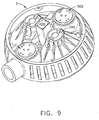
infrared laser designator 400 operated in conjunction with a visiblelight element 200 searchlight in order to covertly position the searchlight prior to illumination with visible light through thesearchlight 3. Alternatively, pilots may need to command and control aninfrared laser designator 400 for targeting purposes and/or for navigational purposes, e.g., to covertly illuminate or designate a building or landing area with or without a searchlight capability. - FIG. 9 is a rear view of a multi-mode lighthead according to an embodiment of the present invention. FIG. 10 is a front view of the multi-mode lighthead shown in FIG. 9. FIG. 11 is a partial, side view of an optical slip ring assembly according to an embodiment of the present invention. FIG. 12 is a schematic view of an exemplary wiring diagram for a multi-mode lighthead of the present invention having visible light, infrared light and/or infrared laser designator capabilities.
- Where an IR laser, e.g., operating at 780 nm or greater, is integrated into the
multi-mode searchlight 3 seen in FIG. 6, e.g., in place of theIR lighting element 302, a pilot or navigator can position thesearchlight 3 to immediately illuminate a target. The mechanical slewing system of the searchlight permits a covert beam to be directed onto the desired object or location. Alternatively, the searchlight can be used to communicate target location or navigational information even while the visiblelight element 200 is not being operated. For example, anIR laser 400 may communicate within a range of approximately 2 miles, thereby providing expanded communication and navigation in a variety of operating conditions. - FIGs. 9 and FIG. 10 are views of a
searchlight 3 incorporating a high power infrared laser, e.g., 50mW or greater and operating at approximately 780 nm or greater within acanopy 2. As seen in FIG. 9 and FIG. 10, theIR laser 400 is mounted in aninsulated housing 410 which in turn is installed in thesearchlight canopy 2, e.g., a PAR-46 NG canopy is used to illustrate this mounting configuration, although alternative canopy designs can be readily incorporated into the present invention as necessary. For example, acanopy 2 havinginfrared modules 302,visible lighting modules 200 and animaging module 1 is shown in FIGs. 9 and 10. However, one of skill in the art will appreciate that acanopy 2 can easily be equipped with alternative arrangements, e.g. a pair ofinfrared modules 302, a pair ofvisible lighting modules 200 and anIR laser 400, thereby excluding theimaging module 1. As seen in FIG. 10, an IR navigational and/or targetinglaser aperture 410 is provided on the front sector of thecanopy 2 for the operation of theIR laser 400. - However, the
IR laser 400 shown in FIGs. 9 and10 does not need to be located within thecanopy 2. Alternatively, thelaser 400 is instead first installed in aninsulated housing 410 and is in turn installed in a remote location away from thecanopy 2, e.g. such as thesearchlight 3 base or other portion on the fuselage of a helicopter or aircraft. One end of a fiber opticlight guide 440 may be attached to thelaser module 400 and the other end may be fed into thecanopy 2. Inside thecanopy 2, the energy from the end of the fiber can be optically re-collimated. - However, in order for the
searchlight 3 to have a 360 degree rotational capability, thefiber optic 440 must incorporate anoptical slip ring 450, such as the one shown in FIG. 11. Theoptical slip ring 450 shown includes a bearing assembly (shown but not labeled), a spherical lens 430, and thenecessary fiber optics 440 for operation in conjunction with aIR laser 400 androtating searchlight 3. However, any optical slip ring assembly having fiber optics, a lens device, a stationary portion, e.g. connecting to theIR laser 400, and a rotating portion, e.g:, connecting to thecanopy 2, may be incorporated into the present invention. - As aforementioned, FIG. 12 is a schematic view of an exemplary wiring diagram for a multi-mode lighthead of the present invention having visible light, infrared light and/or infrared laser designator capabilities. The wiring diagram shown is directed toward a multi-mode lighthead system in which the
IR laser 400 is mounted exterior to the housing of thecanopy 2, e.g., theIR laser 400 is mounted in the vicinity of thecanopy 2 with the use of an optical slip ring as described above. - An additional aspect of the present invention is directed toward a fixed-target tracking searchlight, e.g., employing visible 200 and/or
infrared modules 302 and absolute position sensing. As aforementioned, U.S. Patent No. 6,315, 435 to Hamilton et al., the entirety of which is hereby incorporated by reference, describes an electronically controlled, programmable multi-mode searchlight of the background art particularly useful for mounting on helicopters. This type of searchlight uses a digital electronic control circuit in conjunction with rotary potentiometers to control movement of the searchlight with preset positions. In addition, a micro-processor controlled electronic circuit for operating the searchlight is described by Hamilton et al. The lighthead operates within a predefined range of motion. However, the range of motion may be altered by reprogramming the microprocessor to adjust the corresponding circuit instead of manually adjusting a trimpot. The device described by Hamilton et al. partially sought to eliminate the awkward and time-consuming task of moving micro-switches. - Similarly, the present inventors have determined that helicopter pilots currently and disadvantageously use multi-position momentary switches to control one or more helicopter-mounted searchlights. In addition, the systems of the background art such as that described by Hamilton et al., provide a searchlight capability with absolute position sensing. However, the present invention includes advantageous features such as the implementation of GPS-type position and range data as well as processing and active control capability.
- In many cases, the pilot needs to illuminate a specific object or location on the ground or in the water beneath the helicopter while a search & rescue or other similar mission is performed. As the helicopter moves relative to the fixed target, the pilot must continuously adjust the searchlight position to compensate for this movement. This searchlight control provides additional work-load for the pilot or co-pilot.
- FIG. 13 is a vector diagram of the relationship between a target and a multi-mode, fixed tracking lighthead of the present invention. Upon initial illumination of a fixed-position target, the pilot activates an "acquire" switch. A controllable searchlight with absolute position sensing and a rangefinder accepts helicopter position data, for example GPS (Global Positioning System) data as an input and combines this with range data to the fixed target in order to calculate the absolute location of the fixed target. Active feedback and control of the searchlight provides a way to maintain the searchlight beam passing through this 3D point in space.
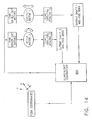
- FIG. 14 is a block diagram of a multi-mode lighthead of the present invention incorporating fixed-target tracking searchlight capability. The fixed target tracking searchlight utilizes a
searchlight controller 500 for processing feedback coordinates from a tracking system, e.g., data such as that shown in FIG. 13. One of skill in the art will appreciate that the searchlight controller can be utilized with modification or duplicated to support additional functions such as theimaging module 1,infrared module 302, etc. In the exemplary system shown in FIG. 14, a first and second power driver circuit motor, a right/left motor, an extend/retract motor, respective gear assemblies with speed and torque scaling and an output shaft for controlling the absolute position sensing of the searchlight is provided and controlled via thesearchlight controller 500. - The fixed-target tracking function is achieved by real-time feedback of the helicopter position location to the searchlight controller and combining this data with the helicopter altitude to establish the "reference" searchlight to target coordinate(X1,Y1,Z1) with a lock vector V1. As seen in FIG. 13 and FIG. 14, when the helicopter position changes, new real-time coordinates (Z2,Y2,Z2) will be updated and processed in combination with the reference (X1,Y1,Z1) coordinates to establish a position correction error which prompts the controller to activate the "extend/retract" and "rotate R/L" motors of the searchlight until a new lock vector V2 on the target with zero error is established. This process will continue as the helicopter moves to another position, e.g., (X3,Y3,Z3) with vector V3 , (X4,Y4,Z4) with vector V4, ...etc.
- If the multi-mode lighthead is employed as a
searchlight 3 for a helicopter, the position-locking searchlight will utilize GPS and rangefinder data to establish object location. The feedback system can automatically lock thesearchlight 3 on an object or target regardless of helicopter movement and without the necessity of pilot control. One of skill in the art will appreciate that the aforementioned embodiment will be particularly useful for SAR, for targeting applications and for generally reducing pilot workload while increasing flight crew safety. - FIG. 15 is a graphical view of a relationship between target and searchlight positions in terms of altitude and/or range. When equipped with rangefinding capability, an operator of the present invention will be able to determine the altitude difference Z2 between the position of a target and the altitude of the searchlight relative to earth. As seen in the FIG. 15, the range is shown as the hypotenuse of the right triangle shown and defined by the angle to target θ. An alternative variation on the embodiment shown in FIG. 15, e.g., ranging with altitude-independence, may be accomplished without rangefinding capabilities, e.g. same-altitude tracking .
- An alternative embodiment of the present invention accepts altitude and GPS-type position information to command the active searchlight to a specific predetermined target or 3D location, intuitively directing a pilot to a target's location. Additionally, the searchlight can be enabled to automatically sweep in a preprogrammed sequence for visual searches of terrain. Accordingly, the multi-mode lighthead and systems described with respect to the present invention provide various combinations of video, laser, visible and infrared lighting, rangefinder and positioning capability.
Claims (5)
- A multi-mode lighthead (100), comprising:a housing (102) having front, rear, top, and bottom sectors;a high power infrared laser (400) within the housing (102);a laser (400) aperture opening at the front sector (122) of the housing (102);at least one high intensity infrared diode (302), said diode being installed into said housing (102) from the rear sector (128) of said housing (102) and positioned to emit infrared light from the front sector (122) of said housing (102); andat least one visible light source (200), said visible light source (200) being installed within said housing (102) from the rear sector (128) of said housing (102) such that said visible light source (200) emits light from the front sector (122) of said housing (102).
- A multi-mode lighthead (100) system, said system comprising:a multi-mode lighthead according to claim 1;a positioning and control system for positioning and controlling the lighthead (100) housing (102); andan attachment portion connected with at least one of said sectors of said housing (102) and interfacing with said positioning and control system.
- A multi-mode light head system according to claim 2, further comprising:an imaging module (1) positioned within said housing (102) to capture an image from said front sector (122) of the housing (102); anda display for viewing and retaining the image from said imaging module (1).
- A multi-mode lighthead (100) system according to claim 2 or claim 3, further comprising:an insulated infrared laser (400) housing (102); andan optical slip ring assembly, said optical slip ring assembly including fiber optics, a lens (308) device, a stationary portion and a rotating portion, wherein said infrared laser (400) is positioned exterior to said housing (102) of said lighthead (100).
- A lighthead (100) comprising:a housing (102) having front, rear, top, and bottom sectors;an attachment portion connected with at least one of said sectors of said housing (102); andat least one of a high intensity infrared diode (302), a visible light source (200), a high power infrared laser (400), and an imaging module (1);said diode (302) being installed into said housing (102) from the rear sector (128) of said housing (102) and positioned to emit infrared light from the front sector (122) of said housing (102);said visible light source (200) being installed within said housing (102) from the rear sector (128) of said housing (102) such that said visible light source (200) emits light from the front sector (122) of said housing (102);said high power infrared laser (400) having a laser (400) aperture opening at the front sector (122) of the housing (102) and operating at approximately 780 nm or greater; andsaid imaging module (1) being positioned within said front sector (122) of the housing (102) for capturing an image.
Applications Claiming Priority (3)
| Application Number | Priority Date | Filing Date | Title |
|---|---|---|---|
| US33279301P | 2001-11-06 | 2001-11-06 | |
| US10/231,216 US6962423B2 (en) | 2001-11-06 | 2002-08-30 | Multi-mode searchlight |
| EP02789433A EP1441952B1 (en) | 2001-11-06 | 2002-11-05 | Multi-mode searchlight |
Related Parent Applications (1)
| Application Number | Title | Priority Date | Filing Date |
|---|---|---|---|
| EP02789433A Division EP1441952B1 (en) | 2001-11-06 | 2002-11-05 | Multi-mode searchlight |
Publications (3)
| Publication Number | Publication Date |
|---|---|
| EP1683720A2 true EP1683720A2 (en) | 2006-07-26 |
| EP1683720A3 EP1683720A3 (en) | 2007-06-27 |
| EP1683720B1 EP1683720B1 (en) | 2008-08-13 |
Family
ID=36589628
Family Applications (1)
| Application Number | Title | Priority Date | Filing Date |
|---|---|---|---|
| EP06112696A Expired - Fee Related EP1683720B1 (en) | 2001-11-06 | 2002-11-05 | Multi-mode searchlight |
Country Status (1)
| Country | Link |
|---|---|
| EP (1) | EP1683720B1 (en) |
Cited By (6)
| Publication number | Priority date | Publication date | Assignee | Title |
|---|---|---|---|---|
| EP1918204A1 (en) * | 2006-10-30 | 2008-05-07 | Honeywell International Inc. | Integrated searchlight lighthead |
| US8118452B2 (en) | 2008-09-11 | 2012-02-21 | Itt Manufacturing Enterprises, Inc. | Searchlight having rotational beam focus for marine applications |
| EP1998600A3 (en) * | 2007-06-01 | 2012-07-25 | Honeywell International Inc. | Dual mode searchlight dimming controller systems and methods |
| CN102897326A (en) * | 2011-07-29 | 2013-01-30 | 尤洛考普特公司 | Rotorcraft, and lighting device with a plurality of operable floodlights achieving functions of landing, hanging and detecting |
| CN106542106A (en) * | 2016-11-14 | 2017-03-29 | 中国南方电网有限责任公司超高压输电公司检修试验中心 | A kind of configurable helicopter laser radar gondola |
| US10882637B1 (en) | 2019-07-17 | 2021-01-05 | Honeywell International Inc. | Systems and methods for search and rescue light control for a rotorcraft |
Citations (4)
| Publication number | Priority date | Publication date | Assignee | Title |
|---|---|---|---|---|
| US4115841A (en) | 1976-12-02 | 1978-09-19 | Eli James Alexander | Searchlight |
| US5589901A (en) | 1995-05-15 | 1996-12-31 | Means; Kevin P. | Apparatus and method for synchronizing search and surveillance devices |
| US5695272A (en) | 1994-05-27 | 1997-12-09 | Grimes Aerospace Company | Search light for aircraft and other vehicles |
| US6315435B1 (en) | 1999-02-18 | 2001-11-13 | Alliedsignal Inc. | Electronically controlled searchlight having multiple preset positions |
Family Cites Families (4)
| Publication number | Priority date | Publication date | Assignee | Title |
|---|---|---|---|---|
| US4513356A (en) * | 1982-01-13 | 1985-04-23 | Ford Motor Company | Replaceable lamp assembly and locking mechanism for a sealable reflector housing |
| DE3622025C1 (en) * | 1986-07-01 | 1987-10-15 | Tele Security Foto Ueberwachun | Infrared luminaire |
| EP1140626B1 (en) * | 1998-12-21 | 2003-03-05 | AlliedSignal Inc. | Ir diode based high intensity light |
| ATE334877T1 (en) * | 2000-12-20 | 2006-08-15 | Honeywell Int Inc | HIGH INTENSITY LAMP WITH IR LASER DIODE |
-
2002
- 2002-11-05 EP EP06112696A patent/EP1683720B1/en not_active Expired - Fee Related
Patent Citations (4)
| Publication number | Priority date | Publication date | Assignee | Title |
|---|---|---|---|---|
| US4115841A (en) | 1976-12-02 | 1978-09-19 | Eli James Alexander | Searchlight |
| US5695272A (en) | 1994-05-27 | 1997-12-09 | Grimes Aerospace Company | Search light for aircraft and other vehicles |
| US5589901A (en) | 1995-05-15 | 1996-12-31 | Means; Kevin P. | Apparatus and method for synchronizing search and surveillance devices |
| US6315435B1 (en) | 1999-02-18 | 2001-11-13 | Alliedsignal Inc. | Electronically controlled searchlight having multiple preset positions |
Cited By (13)
| Publication number | Priority date | Publication date | Assignee | Title |
|---|---|---|---|---|
| EP1918204A1 (en) * | 2006-10-30 | 2008-05-07 | Honeywell International Inc. | Integrated searchlight lighthead |
| US7518133B2 (en) | 2006-10-30 | 2009-04-14 | Honeywell International Inc. | Integrated searchlight lighthead |
| EP1998600A3 (en) * | 2007-06-01 | 2012-07-25 | Honeywell International Inc. | Dual mode searchlight dimming controller systems and methods |
| US8118452B2 (en) | 2008-09-11 | 2012-02-21 | Itt Manufacturing Enterprises, Inc. | Searchlight having rotational beam focus for marine applications |
| US8297806B2 (en) | 2008-09-11 | 2012-10-30 | Xylem Ip Holdings Llc | Searchlight having pull-in bezel retention for marine applications |
| FR2978425A1 (en) * | 2011-07-29 | 2013-02-01 | Eurocopter France | GIRAVION EQUIPPED WITH LIGHTING EQUIPMENT WITH SEVERAL PROJECTORS OPERATED FOR LANDING, WINCHING AND RESEARCH |
| CN102897326A (en) * | 2011-07-29 | 2013-01-30 | 尤洛考普特公司 | Rotorcraft, and lighting device with a plurality of operable floodlights achieving functions of landing, hanging and detecting |
| EP2581310A1 (en) * | 2011-07-29 | 2013-04-17 | Eurocopter | Rotorcraft provided with a lighting apparatus with a plurality of projectors used for landing, hoisting and searching |
| US8836541B2 (en) | 2011-07-29 | 2014-09-16 | Airbus Helicopters | Rotorcraft having lighting equipment with a plurality of headlights operated for landing, winching, and searching |
| CN102897326B (en) * | 2011-07-29 | 2015-06-03 | 空客直升机 | Rotorcraft, and lighting device with a plurality of operable floodlights achieving functions of landing, hanging and detecting |
| CN106542106A (en) * | 2016-11-14 | 2017-03-29 | 中国南方电网有限责任公司超高压输电公司检修试验中心 | A kind of configurable helicopter laser radar gondola |
| US10882637B1 (en) | 2019-07-17 | 2021-01-05 | Honeywell International Inc. | Systems and methods for search and rescue light control for a rotorcraft |
| EP3766735A1 (en) * | 2019-07-17 | 2021-01-20 | Honeywell International Inc. | Systems and methods for search and rescue light control for a rotorcraft |
Also Published As
| Publication number | Publication date |
|---|---|
| EP1683720A3 (en) | 2007-06-27 |
| EP1683720B1 (en) | 2008-08-13 |
Similar Documents
| Publication | Publication Date | Title |
|---|---|---|
| EP1441952B1 (en) | Multi-mode searchlight | |
| AU2002363327A1 (en) | Multi-mode searchlight | |
| EP1343690B1 (en) | Dual mode visible and infrared lighthead | |
| US7690599B2 (en) | Method of illumination for in-flight refueling | |
| US5589901A (en) | Apparatus and method for synchronizing search and surveillance devices | |
| EP1343689B1 (en) | Ir laser diode based high intensity light | |
| EP1124090B1 (en) | Focus control for search lights | |
| WO2015073540A1 (en) | Lighting systems for aircraft operation in a degraded visual environment | |
| EP1683720B1 (en) | Multi-mode searchlight | |
| US5793164A (en) | Low intensity aircraft rotor tip illumination | |
| AU2006201435A1 (en) | Multi-mode searchlight | |
| US11724821B2 (en) | Helicopter search light and method of operating a helicopter search light | |
| US20240002069A1 (en) | Intelligent, steerable, and configurable light for aircraft |
Legal Events
| Date | Code | Title | Description |
|---|---|---|---|
| PUAI | Public reference made under article 153(3) epc to a published international application that has entered the european phase |
Free format text: ORIGINAL CODE: 0009012 |
|
| AC | Divisional application: reference to earlier application |
Ref document number: 1441952 Country of ref document: EP Kind code of ref document: P |
|
| AK | Designated contracting states |
Kind code of ref document: A2 Designated state(s): AT BE BG CH CY CZ DE DK EE ES FI FR GB GR IE IT LI LU MC NL PT SE SK TR |
|
| PUAL | Search report despatched |
Free format text: ORIGINAL CODE: 0009013 |
|
| AK | Designated contracting states |
Kind code of ref document: A3 Designated state(s): AT BE BG CH CY CZ DE DK EE ES FI FR GB GR IE IT LI LU MC NL PT SE SK TR |
|
| 17P | Request for examination filed |
Effective date: 20071213 |
|
| GRAP | Despatch of communication of intention to grant a patent |
Free format text: ORIGINAL CODE: EPIDOSNIGR1 |
|
| AKX | Designation fees paid |
Designated state(s): DE FR GB |
|
| GRAS | Grant fee paid |
Free format text: ORIGINAL CODE: EPIDOSNIGR3 |
|
| GRAA | (expected) grant |
Free format text: ORIGINAL CODE: 0009210 |
|
| AC | Divisional application: reference to earlier application |
Ref document number: 1441952 Country of ref document: EP Kind code of ref document: P |
|
| AK | Designated contracting states |
Kind code of ref document: B1 Designated state(s): DE FR GB |
|
| REG | Reference to a national code |
Ref country code: GB Ref legal event code: FG4D |
|
| REF | Corresponds to: |
Ref document number: 60228346 Country of ref document: DE Date of ref document: 20080925 Kind code of ref document: P |
|
| PGFP | Annual fee paid to national office [announced via postgrant information from national office to epo] |
Ref country code: FR Payment date: 20081106 Year of fee payment: 7 |
|
| PLBE | No opposition filed within time limit |
Free format text: ORIGINAL CODE: 0009261 |
|
| STAA | Information on the status of an ep patent application or granted ep patent |
Free format text: STATUS: NO OPPOSITION FILED WITHIN TIME LIMIT |
|
| 26N | No opposition filed |
Effective date: 20090514 |
|
| PGFP | Annual fee paid to national office [announced via postgrant information from national office to epo] |
Ref country code: GB Payment date: 20091007 Year of fee payment: 8 |
|
| REG | Reference to a national code |
Ref country code: FR Ref legal event code: ST Effective date: 20100730 |
|
| PG25 | Lapsed in a contracting state [announced via postgrant information from national office to epo] |
Ref country code: FR Free format text: LAPSE BECAUSE OF NON-PAYMENT OF DUE FEES Effective date: 20091130 |
|
| GBPC | Gb: european patent ceased through non-payment of renewal fee |
Effective date: 20101105 |
|
| PG25 | Lapsed in a contracting state [announced via postgrant information from national office to epo] |
Ref country code: GB Free format text: LAPSE BECAUSE OF NON-PAYMENT OF DUE FEES Effective date: 20101105 |
|
| PGFP | Annual fee paid to national office [announced via postgrant information from national office to epo] |
Ref country code: DE Payment date: 20180131 Year of fee payment: 16 |
|
| REG | Reference to a national code |
Ref country code: DE Ref legal event code: R119 Ref document number: 60228346 Country of ref document: DE |
|
| PG25 | Lapsed in a contracting state [announced via postgrant information from national office to epo] |
Ref country code: DE Free format text: LAPSE BECAUSE OF NON-PAYMENT OF DUE FEES Effective date: 20190601 |
|
| P01 | Opt-out of the competence of the unified patent court (upc) registered |
Effective date: 20230525 |