EP1669983A1 - System for suppressing rain noise - Google Patents
System for suppressing rain noise Download PDFInfo
- Publication number
- EP1669983A1 EP1669983A1 EP05026904A EP05026904A EP1669983A1 EP 1669983 A1 EP1669983 A1 EP 1669983A1 EP 05026904 A EP05026904 A EP 05026904A EP 05026904 A EP05026904 A EP 05026904A EP 1669983 A1 EP1669983 A1 EP 1669983A1
- Authority
- EP
- European Patent Office
- Prior art keywords
- noise
- rain
- signal
- detector
- input signal
- Prior art date
- Legal status (The legal status is an assumption and is not a legal conclusion. Google has not performed a legal analysis and makes no representation as to the accuracy of the status listed.)
- Withdrawn
Links
Images


Classifications
-
- G—PHYSICS
- G10—MUSICAL INSTRUMENTS; ACOUSTICS
- G10L—SPEECH ANALYSIS OR SYNTHESIS; SPEECH RECOGNITION; SPEECH OR VOICE PROCESSING; SPEECH OR AUDIO CODING OR DECODING
- G10L15/00—Speech recognition
- G10L15/20—Speech recognition techniques specially adapted for robustness in adverse environments, e.g. in noise, of stress induced speech
-
- G—PHYSICS
- G10—MUSICAL INSTRUMENTS; ACOUSTICS
- G10L—SPEECH ANALYSIS OR SYNTHESIS; SPEECH RECOGNITION; SPEECH OR VOICE PROCESSING; SPEECH OR AUDIO CODING OR DECODING
- G10L21/00—Processing of the speech or voice signal to produce another audible or non-audible signal, e.g. visual or tactile, in order to modify its quality or its intelligibility
- G10L21/02—Speech enhancement, e.g. noise reduction or echo cancellation
- G10L21/0208—Noise filtering
- G10L21/0216—Noise filtering characterised by the method used for estimating noise
- G10L21/0232—Processing in the frequency domain
Definitions
- This invention relates to acoustics, and more particularly, to a system that enhances the perceptual quality of sound by reducing interfering noise.
- Voice signals pass from one system to another through a communication medium.
- the clarity of a voice signal does not depend on the quality of the communication system or the quality of the communication medium.
- distortion may interfere with the voice signal, destroy information, and in some instances, masks the voice signal so that it cannot be recognized.
- Noise may come from many sources. In a vehicle, noise may be created by the engine, the road, the tires, or by the surrounding environment. When rain falls onto a vehicle it produces noise that may be heard across a broad frequency spectrum. Some aspects of this noise are predictable, while others are random.
- Some systems attempt to counteract the effects of rain noise by insulating vehicles with a variety of sound-suppressing and dampening materials. While these materials are effective in reducing some noises, the materials also absorb desired signals and do not block the rain noise that may mask a portion of the audio spectrum. Another problem with some speech enhancement systems is that of detecting rain noise. Yet another problem with some speech enhancement systems is that they do not easily adapt to other communication systems.
- This invention provides a voice enhancement logic that improves the perceptual quality of a processed voice.
- the system leams, encodes, and then dampens the noise associated with water striking a surface that includes the surface of a vehicle.
- the system includes a noise detector and a noise attenuator.
- the noise detector detects noise associated with falling water, such as the noise that may be heard during a rainstorm.
- the noise attenuator dampens or reduces some of the detected rain noise.
- Alternative voice enhancement logic includes time frequency transform logic, a background noise estimator, a rain noise detector, and a rain noise attenuator.
- the time frequency transform logic converts a time varying input signal into a frequency domain output signal.
- the background noise estimator measures the continuous noise that may accompany the input signal.
- the rain noise detector automatically identifies and models some of the noise associated with rain, which is then dampened or reduced by the rain noise attenuator.
- Figure 1 is a partial block diagram of voice enhancement logic.
- Figure 2 is a time series plot of noise associated with rain and other sources.
- Figure 3 is a is a time-frequency plot of noise associated with rain and other sources.
- Figure 4 is a waterfall plot of simulated noises of rain and other sources.
- Figure 5 is a block diagram of the voice enhancement logic of Figure 1.
- Figure 6 is a pre-processing system coupled to the voice enhancement logic of Figure 1.
- Figure 7 is an alternative pre-processing system coupled to the voice enhancement logic of Figure 1.
- Figure 8 is a block diagram of an alternative voice enhancement system.
- Figure 9 is a graph of a rain noise masking a portion of a voice signal.
- Figure 10 is a graph of a processed and reconstructed voice signal.
- Figure 11 is a flow diagram of a voice enhancement.
- Figure 12 is a block diagram of voice enhancement logic within a vehicle.
- Figure 13 is a block diagram of voice enhancement logic interfaced to an audio system and/or a navigation system and/or a communication system.
- Figure 14 are waterfall plots of simulated voice combined with noises of rain and other sources.
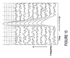
- Figure 15 is a simulated time-frequency plot showing a two-dimensional raindrop noise model.
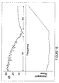
- Figure 16 is a combined frequency-magnitude and frequency-phase plot of a simulated frame containing raindrop noise.
- a voice enhancement logic improves the perceptual quality of a processed voice.
- the logic may automatically leam and encode the shape and form of the noise associated with rain in a real or a delayed time. By tracking selected attributes, the logic may substantially eliminate or dampen rain noise using a memory that temporarily stores the selected attributes of the noise. Alternatively, the logic may also dampen a continuous noise and/or the "musical noise,” squeaks, squawks, chirps, clicks, drips, pops, tones, or other sound artifacts that may be generated by some voice enhancement systems.
- FIG. 1 is a partial block diagram of the voice enhancement logic 100.
- the voice enhancement logic 100 may encompass hardware or software that is capable of running on one or more processors in conjunction with one or more operating systems.
- the highly portable logic includes a rain noise detector 102 and a noise attenuator 104.
- the rain noise detector 102 may identify and model a noise associated with rain that falls onto or strikes a surface. While rain noise may occur across a broad frequency spectrum, the rain noise detector 102 is configured to detect and model the rain noise that is perceived by the ear.
- the rain noise detector 102 receives incoming sound, that in the short term spectra, may be classified into three broad categories: (1) unvoiced, which exhibits noise-like characteristics that may include the noise associated with rain, e.g., it may have some spectral shape but no harmonic or formant structure; (2) fully voiced, which exhibits a regular harmonic structure, or peaks at pitch harmonics weighted by the spectral envelope that may describe the formant structure, and (3) mixed voice, which exhibits a mixture of the above two categories, some parts containing noise-like segments that may include rain noise, the rest exhibiting a regular harmonic structure and/or a formant structure.
- the rain noise detector 102 may separate the noise-like segments from the remaining signal in a real or in a delayed time no matter how complex or how loud an incoming noise segment may be.
- the separated noise-like segments are analyzed to detect the occurrence of rain noise, and in some instances, the presence of a continuous underlying noise.
- the spectrum is modeled, and the model is retained in a memory.
- the rain noise detector 102 may store an entire model of a rain noise signal, it also may store selected attributes in a memory. Some selected attributes may model the noise created by rain striking a surface, the peripheral noise (e.g. in vehicle noise) that may be heard in a rainstorm, or a combination thereof.
- the noise attenuator 104 substantially removes or dampens the rain noise and/or the continuous noise from the unvoiced and mixed voice signals.
- the voice enhancement logic 100 encompasses any system that substantially removes, dampens, or reduces rain noise across a desired frequency spectrum.
- Examples of systems that may dampen or remove rain noise include systems that use a signal and a noise estimate such as (1) systems which use a neural network mapping of a noisy signal and an estimate of the noise to a noise-reduced signal, (2) systems that subtract the noise estimate from a noisy-signal, (3) systems that use the noisy signal and the noise estimate to select a noise-reduced signal from a code-book, (4) systems that in any other way use the noisy signal and the noise estimate to create a noise-reduced signal based on a reconstruction of the masked signal. These systems may attenuate rain noise, and in some instances, attenuate the continuous noise that may be part of the short-term spectra.
- the noise attenuator 104 may also interface or include an optional residual attenuator 106 that removes or dampens artifacts that may be introduced into the processed signal.
- the residual attenuator 106 may remove the "musical noise,” squeaks, squawks, chirps, clicks, drips, pops, tones, or other sound artifacts.
- Figure 2 illustrates an exemplary frame of voice speech and a noisy signal created by water condensed from atmospheric vapor and falling in drops onto a surface.
- the rain pulses 202, 204, and 206 include the sound created by the rain striking a surface.
- the amplitudes of the rain pulses 202, 204, and 206 reflect the relative differences in power or intensity of rain striking a surface as detected by a receiver or a detector.
- the rain pulses 202, 204, and 206 may represent the sound created when natural flowing water strikes a surface such as a window or the sound created when water conveyed under a pressure strikes a surface.
- the continuous noise shown in Figure 2 may include an ambient noise, a noise associated with an engine, a noise created by a powertrain, a road noise, tire noise, other vehicle noises, or any other sounds.
- the continuous noise and rain pulses 202 204 and 206 may range from a substantially linear pulse to a curvilinear pulse.
- the substantially vertical lines of the raindrop transients shown in Figure 3 may not be perfectly straight. Variances may be due to inherent distortion in the rain noise detector 102, the acoustics of the vehicle, and other sources.
- the circuits or hardware that converts sound waves into analog signals or convert the sound waves into digital data may distort the rain drop data.
- the shape of the rain drop transients may change as the signal is detected by or processed by such circuits. This distortion may result in loss of information.
- the distortion may be learned and encoded allowing some of the noise attenuators 104 to substantially remove, dampen, or reduce the distortion.
- Rain drop detection may occur by monitoring segments of frequency forward and/or backward in time. Filter banks or Fast Fourier Transforms ("FFT") may transform sound into the log frequency domain.
- FFT Fast Fourier Transforms
- the rain noise detector 102 identifies the frames that have substantially more energy than their adjacent frequency bands or frames. If a frequency band in a frame has higher energy than in an adjacent frame, the rain noise detector 102 looks for other frequency bands that also have more energy than in their neighboring frames. When the energy within these frequency bands can fit to a model such as straight line as shown in Figure 4 or what may resemble a straight line, the rain noise detector 102 identifies the band as potential rain events.
- rain events may occur when the dispersion or variation of the energy relative to the line (e.g., the standard deviation) is within a predetermined or programmable range. Bands showing energy over neighbor but which are appreciably higher than the model may not be considered to be part of the rain drop noise.
- the noise attenuator 104 replaces the rain drop transient with an estimated value based on the values of adjacent frames.
- the interpolation method may occur with one or more frames positioned backward and/or forward in time and may impose predetermined restrictions and/or prior constraints.
- the noise attenuator 104 adds the learned positions and frequencies to a known or measured constant noise estimate. The noise attenuator 104 then subtracts the noise estimate that includes the modeled rain noise from the noisy signal.
- FIG. 5 is a block diagram of an example rain noise detector 102 that may receive or detect an unvoiced, fully voiced, or a mixed voice input signal.
- a received or detected signal is digitized at a predetermined frequency.
- the voice signal is converted to a pulse-code-modulated (PCM) signal by an analog-to-digital converter 502 (ADC) having any common sample rate.
- a smooth window 504 is applied to a block of data to obtain the windowed signal.
- the complex spectrum for the windowed signal may be obtained by means of a Fast Fourier Transform (FFT) 406 or a filter bank that separates the digitized signals into frequency bins, with each bin identifying an amplitude and phase across a small frequency range.
- FFT Fast Fourier Transform
- Each frequency bin may then be converted into the power-spectral domain 508 and logarithmic domain 510 to develop a rain noise estimate with or without a continuous noise estimate.
- the rain noise detector 102 may derive average rain noise estimates.
- a time-smoothed or weighted average may be used to estimate the rain noise with or without a continuous noise estimate for each frequency bin.
- a line may be fitted to a selected portion of the frequency spectrum.
- a best-fit line may measure the severity of the rain noise within a given block of data.
- a high correlation between the best-fit line and the selected frequency spectrum may identify a rain noise event. Whether or not a high correlation exists, may depend on variations in frequency and amplitude of the rain noise and the presence of voice or other noises.
- the fitting of the line to a suspected rain noise signal may be constrained by rules.
- Exemplary rules may prevent a calculated parametric description such as an offset, a slope, a curvature or a coordinate point in a rain noise model from exceeding an average value.
- Another rule may adjust or modulate the rain noise correction to prevent the noise attenuator 104 from applying a calculated rain noise correction when a vowel or another harmonic structure is detected.
- a harmonic may be identified by its narrow width and its sharp peak, or in conjunction with a voice or a pitch detector. If a vowel or another harmonic structure is detected, the rain noise detector 102 may limit the rain noise correction to values less than or equal to predetermined or average values.
- An additional rule may allow the average rain noise model or its attributes to be updated only during unvoiced segments. If a voiced or a mixed voice segment is detected, the average rain noise model or its attributes are not updated under this rule. If no voice is detected, the rain noise model or each attribute may be updated through any means, such as through a weighted average or a leaky integrator. Many other rules may also be applied to the model. The rules may provide a substantially good linear fit to a suspected rain noise event without masking a voice segment.
- a rain noise attenuator 104 may substantially remove or dampen the rain noise from the noisy spectrum by any method.
- One method may add the rain noise model to a recorded or modeled continuous noise 904. In the power spectrum, the modeled noise may then be subtracted from the unmodified spectrum. If an underlying peak 902 or valley is masked by rain noise as shown in Figure 9 or masked by a continuous noise, a conventional or modified interpolation method may be used to reconstruct the peak and/or valley as shown in Figure 10.
- a linear or step-wise interpolator may be used to reconstruct the missing part of the signal.
- An inverse FFT, filter bank may then be used to convert the signal power to the time domain, which provides a reconstructed voice signal. Alternatively, the signal may be transformed into another frequency transform such as Mel frequency cepstral coefficients.
- an optional residual attenuator 106 may also condition the voice signal before or after it is converted to the time domain.
- the residual attenuator 106 may track the power spectrum within a selected frequency range such as the mid to high frequency range (e.g., more than about 1000 Hz).
- a large increase in signal power is detected an improvement may be obtained by limiting or dampening the transmitted power in that range to a predetermined or calculated threshold.
- a calculated threshold may be equal to, or based on, the average spectral power of that same frequency range at an earlier period in time.
- pre-conditioning the input signal before the rain noise detector 102 processes it may exploit the lag time that a signal may arrive at different detectors that are positioned apart as shown in Figure 6. If multiple detectors or microphones 602 are used that convert sound into an electric signal, the pre-processing system may include control logic 604 that automatically selects the microphone 602 and channel that senses the least amount of rain noise. When another microphone 602 is selected, the electric signal may be combined with the previously generated signal before being processed by the rain noise detector 102.
- multiple rain noise detectors 102 may be used to analyze the input of each of the microphones 602 as shown in Figure 7. Spectral rain noise estimates may be made on each of the channels. A mixing of one or more channels may occur by switching between the outputs of the microphones 602. The signals may be evaluated and selected on a frequency-by-frequency basis. Alternatively, control logic 702 may combine the output signals of multiple rain noise detectors 102 at a specific frequency or frequency range through a weighting function.
- Figure 8 is alternative voice enhancement logic 800 that also improves the perceptual quality of a processed voice.
- the enhancement is accomplished by time-frequency transform logic 802 that digitizes and converts a time varying signal to the frequency domain.
- a background noise estimator 804 measures the continuous or ambient noise that occurs near a sound source or the receiver.
- the background noise estimator 804 may comprise a power detector that averages the acoustic power in each frequency bin.
- a transient detector 806 disables the noise estimation process during unexpected or unpredictable increases in power.
- the transient detector 806 may disable the background noise,estimator 704 when an instantaneous background noise B(f, i) exceeds an average background noise B (f) Ave by more than a selected decibel level ' c .
- This relationship may be expressed as: B ( f , i ) > B ( f ) A v e + c
- a rain noise detector 708 may fit a line to a selected portion of the spectrum. Through a regression, a best-fit line may model the severity of the rain noise 202. To limit any masking of voice, the fitting of the line to a suspected range of rain noise may be constrained by the rules described above.
- a rain event may be identified when a high correlation between a fitted line and the noise associated with rain is detected. Whether or not a high correlation exists, may depend on a desired clarity of a processed voice and the variations in frequency and amplitude of the rain noise.
- a rain event may be identified by the analysis of time varying spectral characteristics of the input signal that may be graphically displayed on a spectrogram.
- a spectrogram is a two dimensional pattern as shown in Figure 3 in which the vertical dimensions correspond to frequency and the horizontal dimensions correspond to time.
- a signal discriminator 810 may mark the voice and noise of the spectrum in real or delayed time. Any method may be used to distinguish voice from noise.
- voiced signals may be identified by (1) the narrow widths of their bands or peaks; (2) the resonant structure that may be harmonically related; (3) the resonances or broad peaks that correspond to formant frequencies; (4) characteristics that change relatively slowly with time; (5) their durations; and when multiple detectors or microphones are used, (6) the correlation of the output signals of the detectors or microphones, and many other attributes and/or combinations.
- a rain noise attenuator 812 may dampen or substantially remove the rain noise from the noisy spectrum by any method.
- One method may add the periodic rain noise pulses to a recorded or modeled continuous noise. In the power spectrum, the modeled noise may then be removed from the unmodified spectrum by the means described above. If an underlying peak or valley 902 is masked by rain noise 202 as shown in Figure 9 or masked by a continuous noise, a conventional or modified interpolation method may be used to reconstruct the peak and/or valley as shown in Figure 10. A linear or step-wise interpolator may be used to reconstruct the missing part of the signal. A time series synthesizer may then be used to convert the signal power to the time domain, which provides a reconstructed voice signal.
- an optional residual attenuator 814 may also be used.
- the residual attenuator 814 may track the power spectrum within a frequency range.
- a calculated threshold may be equal to or based on the average spectral power of that same frequency range at a period earlier or later in time.
- FIG 11 is a flow diagram of a voice enhancement that removes some rain noise and continuous noise to enhance the perceptual quality of a processed voice.
- a received or detected signal is digitized at a predetermined frequency.
- the voice signal may be converted to a PCM signal by an ADC.
- a complex spectrum for the windowed signal may be obtained by means of an FFT or filter bank that separates the digitized signals into frequency bins, with each bin identifying an amplitude and a phase across a small frequency range.
- the background noise estimate may comprise an average of the acoustic power in each frequency bin.
- the noise estimation process may be disabled during abnormal or unpredictable increases in power at act 1108.
- the transient detection act 1108 disables the background noise estimate when an instantaneous background noise exceeds an average background noise by more than a predetermined decibel level.
- a rain event may be detected when a high correlation exits between a best-fit line and a selected portion of the frequency spectrum.
- a rain event may be identified by the analysis of time varying spectral characteristics of the input signal.
- the fitting of the line to the suspected rain signal may be constrained by some optional acts. Exemplary optional acts may prevent a calculated offset, slope, or coordinate point in a rain noise model from exceeding an average value.
- Another optional act may prevent the rain noise detection method from applying a calculated rain noise correction when a vowel or another harmonic structure is detected. If a vowel or another harmonic structure is detected, the rain noise detection method may limit the rain noise correction to values less than or equal to predetermined or average values.
- An additional optional act may allow the average rain noise model or attributes to be updated only during unvoiced segments. If a voiced or mixed voice segment is detected, the average rain noise model or attributes are not updated under this act. If no voice is detected, the rain noise model or each attribute may be updated through many means, such as through a weighted average or a leaky integrator. Many other optional acts may also be applied to the model.
- a signal analysis may discriminate or mark the voice signal from the noise-like segments.
- Voiced signals may be identified by any means including, for example, (1) the narrow widths of their bands or peaks; (2) the resonant structure that may be harmonically related; (3) their harmonics that correspond to formant frequencies; (4) characteristics that change relatively slowly with time; (5) their durations; and when multiple detectors or microphones are used, (6) the correlation of the output signals of the detectors or microphones.
- a rain noise is substantially removed or dampened from the noisy spectrum by any act.
- One exemplary act 1114 adds the substantially periodic rain pulses to a recorded or modeled continuous noise. In the power spectrum, the modeled noise may then be substantially removed from the unmodified spectrum by the methods and systems described above. If an underlying peak or valley 902 is masked by a rain event 202 as shown in Figure 9 or masked by a continuous noise 902, a conventional or modified interpolation method may be used to reconstruct the peak and/or valley at act 1116. A time series synthesis may then be used to convert the signal power to the time domain at act 1120, which provides a reconstructed voice signal.
- a residual attenuation method may also be performed before the signal is converted back to the time domain.
- An optional residual attenuation method 1118 may track the power spectrum within a frequency range. When a large increase in signal power is detected an improvement may be obtained by limiting the transmitted power in that frequency range to a predetermined or calculated threshold. A calculated threshold may be equal to or based on the average spectral power of that same frequency range at a period earlier or later in time.
- the method shown in Figure 11 may be encoded in a signal bearing medium, a computer readable medium such as a memory, programmed within a device such as one or more integrated circuits, or processed by a controller or a computer. If the methods are performed by software, the software may reside in a memory resident to or interfaced to the rain noise detector 102, noise attenuator 104, a communication interface, or any other type of non-volatile or volatile memory interfaced or resident to the voice enhancement logic 100 or 800.
- the memory may include an ordered listing of executable instructions for implementing logical functions. A logical function may be implemented through digital circuitry, through source code, through analog circuitry, or through an analog source such through an analog electrical, audio, or video signal.
- the software may be embodied in any computer-readable or signal-bearing medium, for use by, or in connection with an instruction executable system, apparatus, or device.
- a system may include a computer-based system, a processor-containing system, or another system that may selectively fetch instructions from an instruction executable system, apparatus, or device that may also execute instructions.
- a “computer-readable medium,” “machine-readable medium,” “propagated-signal” medium, and/or “signal-bearing medium” may comprise any means that contains, stores, communicates, propagates, or transports software for use by or in connection with an instruction executable system, apparatus, or device.
- the machine-readable medium may selectively be, but not limited to, an electronic, magnetic, optical, electromagnetic, infrared, or semiconductor system, apparatus, device, or propagation medium.
- a non-exhaustive list of examples of a machine-readable medium would include: an electrical connection "electronic” having one or more wires, a portable magnetic or optical disk, a volatile memory such as a Random Access Memory “RAM” (electronic), a Read-Only Memory “ROM” (electronic), an Erasable Programmable Read-Only Memory (EPROM or Flash memory) (electronic), or an optical fiber (optical).
- a machine-readable medium may also include a tangible medium upon which software is printed, as the software may be electronically stored as an image or in another format (e.g., through an optical scan), then compiled, and/or interpreted or otherwise processed. The processed medium may then be stored in a computer and/or machine memory.
- a system may (1) detect periodic peaks in the spectra having a SNR greater than a predetermined threshold; (2) identify the peaks having a width greater than a predetermined threshold; (3) identify peaks that lack a harmonic relationships; (4) compare peaks with previous voiced spectra; and (5) compare signals detected from different microphones before differentiating the rain noise segments, other noise like segments, and regular harmonic structures.
- One or more of the systems described above may also be used in alternative voice enhancement logic.
- voice enhancement systems include combinations of the structure and functions described above. These voice enhancement systems are formed from any combination of structure and function described above or illustrated within the attached figures.
- the logic may be implemented in software or hardware.
- logic is intended to broadly encompass a hardware device or circuit, software, or a combination.
- the hardware may include a processor or a controller having volatile and/or non-volatile memory and may also include interfaces between devices through wireless and/or hardwire mediums.
- the wireless interfaces may utilize Zigbee, Wi-Fi, WiMax, Mobile-Fi, Ultrawideband, Bluetooth, cellular and any other wireless technologies or combination.
- the voice enhancement logic is easily adaptable to any technology or devices.
- Some voice enhancement systems or components interface or couple devices or structures for transporting people or things such as the vehicle shown in Figure 12.
- Some voice enhancement systems or components interface or couple instruments that convert voice and other sounds into a form that may be transmitted to remote locations, such as landline and wireless devices, audio equipment, navigation equipment as shown in Figure 13, and other communication systems that may be susceptible to rain noise.
- the voice enhancement logic improves the perceptual quality of a processed voice.
- the logic may automatically learn and encode the shape and form of the noise associated with the movement of water and/or the noise associated with water striking a surface in a real or a delayed time. By tracking substantially all or some of the selected attributes, the logic may eliminate, dampen, or reduce the water related noise using a memory that temporarily or permanently stores the attributes of that noise.
- the voice enhancement logic may also dampen a continuous noise and/or the squeaks, squawks, chirps, clicks, drips, pops, tones, or other sound artifacts that may be generated within some voice enhancement systems and may reconstruct voice when needed.
- FIG. 15 Another alternate method of rain drop detection uses a two-dimensional model of rain drop intensity in both time and frequency.
- An example of a possible time-frequency model for rain drop detection is shown in Figure 15.
- rain drop noise may be wide-band, substantially similar intensity-vs.-time profiles may be expected in the frequency ranges involved in the raindrop event. All frequencies involved in the rain may plot rise at approximately the same time, but may have different peak values, durations, and decay rates.
- the rain detector may also consider that part of the rain drop may be masked by louder sounds, such as voice harmonics, and may partially or fully exclude these frequency ranges from the rain model. This exclusion may be explicit, by scanning for probable non-rain features before modeling, or implicit, by choosing a modeling method that allows values to significantly exceed the selected model.
- Detection may involve fitting a predefined rain model to the spectrum and determining the quality of the match, as well as possibly identifying which frequency ranges are involved in the rain drop event.
- the included frequency ranges may be continuous or discontinuous; in addition, all or part of the spectrum may be identified as being only partially involved in the raindrop event.
- the parameters used to model the rain drop noise may be constrained to be within predetermined and/or adaptive limits, which may be a function of frequency, presence of voice, characteristics of recently detected raindrops, average time between raindrops, or any other internal or external data which can be made available to the rain detector.
- these parameters may include rain drop duration, peak intensity, rise and fall rates, allowable intensity variation between different frequency ranges.
- a further refinement of this rain detection method is a method for estimating the likelihood of a rapid rise being part of a raindrop and estimating the raindrop model parameters without complete future information.
- the rate of energy increase, and the range of frequencies involved in the increase may be used as a primary detection method.
- the expected duration and rate of decay in the estimated model may be used at a nearby future time to verify that the detected raindrop continues to fit the estimated model.
- the rain noise attenuator may discontinue or reduce attenuation if the raindrop does not behave as predicted.
- the rain drop model may simply decay as predicted and allow the signal to pass through unattenuated once the model drops below the level of the rain noise estimate.
- a further refinement uses additional observed properties of raindrop spectra to assist the detector in distinguishing between rain and non-rain signals.
- One distinguishing feature of the rain drop noise may be the continuity of the magnitude and/or phase of its spectrum across many adjacent frequency bins.
- the portion of the spectrum dominated by rain noise 1602 has a significantly smoother magnitude plot than the portion dominated by other noise sources 1601.
- Certain types of rain drop noise may have a significantly flatter and/or smoother magnitude than a spectrum containing voice or other speech sounds.
- One or more mathematical measures of a spectrum's flatness or smoothness may be used, on part or all of the spectrum, to improve the distinction between rain and voice spectra. This measure, which may be computed for the entire spectrum for predefined bands, or continuously using a sliding window across the entire spectrum, may be used to help decide whether a raindrop noise is present and how involved each frequency is in the raindrop.
- An example of a smoothness measure is the sum of absolute differences algorithm, which computes the absolute value of the difference in magnitude or logarithmic magnitude between adjacent frequency bins, and summing this over a number of bins to produce a value that is generally small for smooth spectra and greater for spectra with large variations between the intensity of adjacent frequency bins.
- An example of a flatness measure is the Spectral Flatness Measure (SFM) which may be found by computing the ratio of the geometric mean of the magnitude spectrum to its arithmetic mean.
- SFM Spectral Flatness Measure
- Phase continuity may also be used to distinguish rain drop noises from other sounds.
- the rain drop noise may be represented by a short high-energy burst in the time domain, and this may cause the unwrapped phases of the FFT result to be locally linear as illustrated in the phase plot in the portion of the spectrum dominated by rain noise 1602.
- One method for determining the local linearity of phases is to take the absolute value of the second derivative of the unwrapped phase, then smoothing this in frequency. This measure may produce values close to zero for regions of the spectrum dominated by impulse-like noise and values significantly greater than zero in regions dominated by other types of sound, such as tonal sound or longer-duration noise. This measure may be used to assist with distinguishing transients such as rain drop noise from tonal or speech sounds.
- the value of the slope in the linear part of the phase plot may be directly relatable to the position of the transient within the time-series signal, allowing a time-based detection or removal method to more precisely detect and/or remove the disturbance in the time domain.
- the rain detection module may communicate with other devices in the vehicle to adjust the behavior of the rain detector and remover depending on the status of other systems in the vehicle (e.g. the windshield wiper controller). It may, for example, be desirable to enable the rain detection logic 102 only when the windshield wipers are switched on and/or to adjust the parameters of the rain drop model depending on the speed of the wipers. Conversely, the rain detector may transmit information about the intensity and average time between raindrop-like noises to the wiper controller, which may enhance its ability to intelligently control the wipers without driver intervention.
Landscapes
- Engineering & Computer Science (AREA)
- Multimedia (AREA)
- Health & Medical Sciences (AREA)
- Audiology, Speech & Language Pathology (AREA)
- Human Computer Interaction (AREA)
- Physics & Mathematics (AREA)
- Acoustics & Sound (AREA)
- Computational Linguistics (AREA)
- Quality & Reliability (AREA)
- Signal Processing (AREA)
- Circuit For Audible Band Transducer (AREA)
- Measurement Of Mechanical Vibrations Or Ultrasonic Waves (AREA)
- Telephone Function (AREA)
- Noise Elimination (AREA)
Abstract
Description
- This application is a continuation in-part of U.S. Application No. 10/688,802 "System for Suppressing Wind Noise," filed October 16, 2003, which is a continuation in-part of U.S. Application No. 10/410,736, "Method and Apparatus for Suppressing Wind Noise," filed April 10, 2003, which claims priority to U.S. Application No. 60/449, 511 "Method for Suppressing Wind Noise" filed on February 21, 2003. The disclosures of the above applications are incorporated herein by reference.
- This invention relates to acoustics, and more particularly, to a system that enhances the perceptual quality of sound by reducing interfering noise.
- Many hands-free communication devices acquire, assimilate, and transfer a voice signal. Voice signals pass from one system to another through a communication medium. In some systems, including those used in vehicles, the clarity of a voice signal does not depend on the quality of the communication system or the quality of the communication medium. When noise occurs near a source or a receiver, distortion may interfere with the voice signal, destroy information, and in some instances, masks the voice signal so that it cannot be recognized.
- Noise may come from many sources. In a vehicle, noise may be created by the engine, the road, the tires, or by the surrounding environment. When rain falls onto a vehicle it produces noise that may be heard across a broad frequency spectrum. Some aspects of this noise are predictable, while others are random.
- Some systems attempt to counteract the effects of rain noise by insulating vehicles with a variety of sound-suppressing and dampening materials. While these materials are effective in reducing some noises, the materials also absorb desired signals and do not block the rain noise that may mask a portion of the audio spectrum. Another problem with some speech enhancement systems is that of detecting rain noise. Yet another problem with some speech enhancement systems is that they do not easily adapt to other communication systems.
- Therefore there is a need for a system that counteracts the noise associated with water striking a surface across a varying frequency range.
- This invention provides a voice enhancement logic that improves the perceptual quality of a processed voice. The system leams, encodes, and then dampens the noise associated with water striking a surface that includes the surface of a vehicle. The system includes a noise detector and a noise attenuator. The noise detector detects noise associated with falling water, such as the noise that may be heard during a rainstorm. The noise attenuator dampens or reduces some of the detected rain noise.
- Alternative voice enhancement logic includes time frequency transform logic, a background noise estimator, a rain noise detector, and a rain noise attenuator. The time frequency transform logic converts a time varying input signal into a frequency domain output signal. The background noise estimator measures the continuous noise that may accompany the input signal. The rain noise detector automatically identifies and models some of the noise associated with rain, which is then dampened or reduced by the rain noise attenuator.
- Other systems, methods, features and advantages of the invention will be, or will become, apparent to one with skill in the art upon examination of the following figures and detailed description. It is intended that all such additional systems, methods, features and advantages be included within this description, be within the scope of the invention, and be protected by the following claims.
- The invention can be better understood with reference to the following drawings and description. The components in the figures are not necessarily to scale, emphasis instead being placed upon illustrating the principles of the invention. Moreover, in the figures, like referenced numerals designate corresponding parts throughout the different views.
- Figure 1 is a partial block diagram of voice enhancement logic.
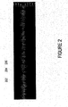
- Figure 2 is a time series plot of noise associated with rain and other sources.
- Figure 3 is a is a time-frequency plot of noise associated with rain and other sources.
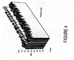
- Figure 4 is a waterfall plot of simulated noises of rain and other sources.
- Figure 5 is a block diagram of the voice enhancement logic of Figure 1.
- Figure 6 is a pre-processing system coupled to the voice enhancement logic of Figure 1.
- Figure 7 is an alternative pre-processing system coupled to the voice enhancement logic of Figure 1.
- Figure 8 is a block diagram of an alternative voice enhancement system.
- Figure 9 is a graph of a rain noise masking a portion of a voice signal.
- Figure 10 is a graph of a processed and reconstructed voice signal.
- Figure 11 is a flow diagram of a voice enhancement.
- Figure 12 is a block diagram of voice enhancement logic within a vehicle.
- Figure 13 is a block diagram of voice enhancement logic interfaced to an audio system and/or a navigation system and/or a communication system.
- Figure 14 are waterfall plots of simulated voice combined with noises of rain and other sources.
- Figure 15 is a simulated time-frequency plot showing a two-dimensional raindrop noise model.
- Figure 16 is a combined frequency-magnitude and frequency-phase plot of a simulated frame containing raindrop noise.
- A voice enhancement logic improves the perceptual quality of a processed voice. The logic may automatically leam and encode the shape and form of the noise associated with rain in a real or a delayed time. By tracking selected attributes, the logic may substantially eliminate or dampen rain noise using a memory that temporarily stores the selected attributes of the noise. Alternatively, the logic may also dampen a continuous noise and/or the "musical noise," squeaks, squawks, chirps, clicks, drips, pops, tones, or other sound artifacts that may be generated by some voice enhancement systems.
- Figure 1 is a partial block diagram of the
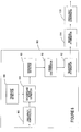
voice enhancement logic 100. Thevoice enhancement logic 100 may encompass hardware or software that is capable of running on one or more processors in conjunction with one or more operating systems. The highly portable logic includes arain noise detector 102 and anoise attenuator 104. - In Figure 1 the
rain noise detector 102 may identify and model a noise associated with rain that falls onto or strikes a surface. While rain noise may occur across a broad frequency spectrum, therain noise detector 102 is configured to detect and model the rain noise that is perceived by the ear. Therain noise detector 102 receives incoming sound, that in the short term spectra, may be classified into three broad categories: (1) unvoiced, which exhibits noise-like characteristics that may include the noise associated with rain, e.g., it may have some spectral shape but no harmonic or formant structure; (2) fully voiced, which exhibits a regular harmonic structure, or peaks at pitch harmonics weighted by the spectral envelope that may describe the formant structure, and (3) mixed voice, which exhibits a mixture of the above two categories, some parts containing noise-like segments that may include rain noise, the rest exhibiting a regular harmonic structure and/or a formant structure. - The
rain noise detector 102 may separate the noise-like segments from the remaining signal in a real or in a delayed time no matter how complex or how loud an incoming noise segment may be. The separated noise-like segments are analyzed to detect the occurrence of rain noise, and in some instances, the presence of a continuous underlying noise. When rain noise is detected, the spectrum is modeled, and the model is retained in a memory. While therain noise detector 102 may store an entire model of a rain noise signal, it also may store selected attributes in a memory. Some selected attributes may model the noise created by rain striking a surface, the peripheral noise (e.g. in vehicle noise) that may be heard in a rainstorm, or a combination thereof. - To overcome the effects of rain noise, and in some instances, the underlying continuous noise that may include ambient noise, the
noise attenuator 104 substantially removes or dampens the rain noise and/or the continuous noise from the unvoiced and mixed voice signals. Thevoice enhancement logic 100 encompasses any system that substantially removes, dampens, or reduces rain noise across a desired frequency spectrum. Examples of systems that may dampen or remove rain noise include systems that use a signal and a noise estimate such as (1) systems which use a neural network mapping of a noisy signal and an estimate of the noise to a noise-reduced signal, (2) systems that subtract the noise estimate from a noisy-signal, (3) systems that use the noisy signal and the noise estimate to select a noise-reduced signal from a code-book, (4) systems that in any other way use the noisy signal and the noise estimate to create a noise-reduced signal based on a reconstruction of the masked signal. These systems may attenuate rain noise, and in some instances, attenuate the continuous noise that may be part of the short-term spectra. Thenoise attenuator 104 may also interface or include an optionalresidual attenuator 106 that removes or dampens artifacts that may be introduced into the processed signal. Theresidual attenuator 106 may remove the "musical noise," squeaks, squawks, chirps, clicks, drips, pops, tones, or other sound artifacts. - Figure 2 illustrates an exemplary frame of voice speech and a noisy signal created by water condensed from atmospheric vapor and falling in drops onto a surface. The
rain pulses rain pulses rain pulses - In the frequency spectral domain shown in Figure 3, the continuous noise and
rain pulses 202 204 and 206 may range from a substantially linear pulse to a curvilinear pulse. The substantially vertical lines of the raindrop transients shown in Figure 3 may not be perfectly straight. Variances may be due to inherent distortion in therain noise detector 102, the acoustics of the vehicle, and other sources. In somerain noise detectors 102 or the devices that may interface therain noise detector 102, the circuits or hardware that converts sound waves into analog signals or convert the sound waves into digital data may distort the rain drop data. The shape of the rain drop transients may change as the signal is detected by or processed by such circuits. This distortion may result in loss of information. In some voice enhancement logic, the distortion may be learned and encoded allowing some of thenoise attenuators 104 to substantially remove, dampen, or reduce the distortion. - Rain drop detection may occur by monitoring segments of frequency forward and/or backward in time. Filter banks or Fast Fourier Transforms ("FFT") may transform sound into the log frequency domain. Through a comparison, the
rain noise detector 102 identifies the frames that have substantially more energy than their adjacent frequency bands or frames. If a frequency band in a frame has higher energy than in an adjacent frame, therain noise detector 102 looks for other frequency bands that also have more energy than in their neighboring frames. When the energy within these frequency bands can fit to a model such as straight line as shown in Figure 4 or what may resemble a straight line, therain noise detector 102 identifies the band as potential rain events. In somerain noise detectors 102 rain events may occur when the dispersion or variation of the energy relative to the line (e.g., the standard deviation) is within a predetermined or programmable range. Bands showing energy over neighbor but which are appreciably higher than the model may not be considered to be part of the rain drop noise. - Once the relative magnitudes and durations of the rain drop transients are learned, their removal may be accomplished by many methods. In one method, the
noise attenuator 104 replaces the rain drop transient with an estimated value based on the values of adjacent frames. The interpolation method may occur with one or more frames positioned backward and/or forward in time and may impose predetermined restrictions and/or prior constraints. In an alternative method, thenoise attenuator 104 adds the learned positions and frequencies to a known or measured constant noise estimate. Thenoise attenuator 104 then subtracts the noise estimate that includes the modeled rain noise from the noisy signal. - Figure 5 is a block diagram of an example
rain noise detector 102 that may receive or detect an unvoiced, fully voiced, or a mixed voice input signal. A received or detected signal is digitized at a predetermined frequency. To assure a good quality voice, the voice signal is converted to a pulse-code-modulated (PCM) signal by an analog-to-digital converter 502 (ADC) having any common sample rate. Asmooth window 504 is applied to a block of data to obtain the windowed signal. The complex spectrum for the windowed signal may be obtained by means of a Fast Fourier Transform (FFT) 406 or a filter bank that separates the digitized signals into frequency bins, with each bin identifying an amplitude and phase across a small frequency range. Each frequency bin may then be converted into the power-spectral domain 508 andlogarithmic domain 510 to develop a rain noise estimate with or without a continuous noise estimate. As more windows of sound are processed, therain noise detector 102 may derive average rain noise estimates. A time-smoothed or weighted average may be used to estimate the rain noise with or without a continuous noise estimate for each frequency bin. - To detect a rain event, a line may be fitted to a selected portion of the frequency spectrum. Through a regression, a best-fit line may measure the severity of the rain noise within a given block of data. A high correlation between the best-fit line and the selected frequency spectrum may identify a rain noise event. Whether or not a high correlation exists, may depend on variations in frequency and amplitude of the rain noise and the presence of voice or other noises.
- To limit a masking of voice, the fitting of the line to a suspected rain noise signal may be constrained by rules. Exemplary rules may prevent a calculated parametric description such as an offset, a slope, a curvature or a coordinate point in a rain noise model from exceeding an average value. Another rule may adjust or modulate the rain noise correction to prevent the
noise attenuator 104 from applying a calculated rain noise correction when a vowel or another harmonic structure is detected. A harmonic may be identified by its narrow width and its sharp peak, or in conjunction with a voice or a pitch detector. If a vowel or another harmonic structure is detected, therain noise detector 102 may limit the rain noise correction to values less than or equal to predetermined or average values. An additional rule may allow the average rain noise model or its attributes to be updated only during unvoiced segments. If a voiced or a mixed voice segment is detected, the average rain noise model or its attributes are not updated under this rule. If no voice is detected, the rain noise model or each attribute may be updated through any means, such as through a weighted average or a leaky integrator. Many other rules may also be applied to the model. The rules may provide a substantially good linear fit to a suspected rain noise event without masking a voice segment. - To overcome the effects of rain noise, a
rain noise attenuator 104 may substantially remove or dampen the rain noise from the noisy spectrum by any method. One method may add the rain noise model to a recorded or modeledcontinuous noise 904. In the power spectrum, the modeled noise may then be subtracted from the unmodified spectrum. If anunderlying peak 902 or valley is masked by rain noise as shown in Figure 9 or masked by a continuous noise, a conventional or modified interpolation method may be used to reconstruct the peak and/or valley as shown in Figure 10. A linear or step-wise interpolator may be used to reconstruct the missing part of the signal. An inverse FFT, filter bank, may then be used to convert the signal power to the time domain, which provides a reconstructed voice signal. Alternatively, the signal may be transformed into another frequency transform such as Mel frequency cepstral coefficients. - To minimize the "music noise," squeaks, squawks, chirps, clicks, drips, pops, tones, or other sound artifacts that may be generated in a selected frequency range by some rain noise attenuators, an optional residual attenuator 106 (shown in Figure 1) may also condition the voice signal before or after it is converted to the time domain. The
residual attenuator 106 may track the power spectrum within a selected frequency range such as the mid to high frequency range (e.g., more than about 1000 Hz). When a large increase in signal power is detected an improvement may be obtained by limiting or dampening the transmitted power in that range to a predetermined or calculated threshold. A calculated threshold may be equal to, or based on, the average spectral power of that same frequency range at an earlier period in time. - Further improvements to voice quality may be achieved by pre-conditioning the input signal before the
rain noise detector 102 processes it. One pre-processing system may exploit the lag time that a signal may arrive at different detectors that are positioned apart as shown in Figure 6. If multiple detectors ormicrophones 602 are used that convert sound into an electric signal, the pre-processing system may includecontrol logic 604 that automatically selects themicrophone 602 and channel that senses the least amount of rain noise. When anothermicrophone 602 is selected, the electric signal may be combined with the previously generated signal before being processed by therain noise detector 102. - Alternatively, multiple
rain noise detectors 102 may be used to analyze the input of each of themicrophones 602 as shown in Figure 7. Spectral rain noise estimates may be made on each of the channels. A mixing of one or more channels may occur by switching between the outputs of themicrophones 602. The signals may be evaluated and selected on a frequency-by-frequency basis. Alternatively,control logic 702 may combine the output signals of multiplerain noise detectors 102 at a specific frequency or frequency range through a weighting function. - Figure 8 is alternative
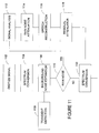
voice enhancement logic 800 that also improves the perceptual quality of a processed voice. The enhancement is accomplished by time-frequency transform logic 802 that digitizes and converts a time varying signal to the frequency domain. Abackground noise estimator 804 measures the continuous or ambient noise that occurs near a sound source or the receiver. Thebackground noise estimator 804 may comprise a power detector that averages the acoustic power in each frequency bin. To prevent biased noise estimations at non-periodic transients, atransient detector 806 disables the noise estimation process during unexpected or unpredictable increases in power. In Figure 8, thetransient detector 806 may disable the background noise,estimator 704 when an instantaneous background noise B(f, i) exceeds an average background noise B (f) Ave by more than a selected decibel level 'c. ' This relationship may be expressed as:
- To detect a rain event, a rain noise detector 708 may fit a line to a selected portion of the spectrum. Through a regression, a best-fit line may model the severity of the
rain noise 202. To limit any masking of voice, the fitting of the line to a suspected range of rain noise may be constrained by the rules described above. A rain event may be identified when a high correlation between a fitted line and the noise associated with rain is detected. Whether or not a high correlation exists, may depend on a desired clarity of a processed voice and the variations in frequency and amplitude of the rain noise. - Alternatively, a rain event may be identified by the analysis of time varying spectral characteristics of the input signal that may be graphically displayed on a spectrogram. A spectrogram is a two dimensional pattern as shown in Figure 3 in which the vertical dimensions correspond to frequency and the horizontal dimensions correspond to time.
- A
signal discriminator 810 may mark the voice and noise of the spectrum in real or delayed time. Any method may be used to distinguish voice from noise. In Figure 7, voiced signals may be identified by (1) the narrow widths of their bands or peaks; (2) the resonant structure that may be harmonically related; (3) the resonances or broad peaks that correspond to formant frequencies; (4) characteristics that change relatively slowly with time; (5) their durations; and when multiple detectors or microphones are used, (6) the correlation of the output signals of the detectors or microphones, and many other attributes and/or combinations. - To overcome the effects of rain noise, a
rain noise attenuator 812 may dampen or substantially remove the rain noise from the noisy spectrum by any method. One method may add the periodic rain noise pulses to a recorded or modeled continuous noise. In the power spectrum, the modeled noise may then be removed from the unmodified spectrum by the means described above. If an underlying peak orvalley 902 is masked byrain noise 202 as shown in Figure 9 or masked by a continuous noise, a conventional or modified interpolation method may be used to reconstruct the peak and/or valley as shown in Figure 10. A linear or step-wise interpolator may be used to reconstruct the missing part of the signal. A time series synthesizer may then be used to convert the signal power to the time domain, which provides a reconstructed voice signal. - To minimize the "musical noise," squeaks, squawks, chirps, clicks, drips, pops, tones, or other sound artifacts that may be generated in a selected frequency range by some rain noise attenuators, an optional
residual attenuator 814 may also be used. Theresidual attenuator 814 may track the power spectrum within a frequency range. When a large increase in signal power is detected an improvement may be obtained by limiting the transmitted power in the frequency range to a predetermined or calculated threshold. A calculated threshold may be equal to or based on the average spectral power of that same frequency range at a period earlier or later in time. - Figure 11 is a flow diagram of a voice enhancement that removes some rain noise and continuous noise to enhance the perceptual quality of a processed voice. At act 1102 a received or detected signal is digitized at a predetermined frequency. To assure a good quality voice, the voice signal may be converted to a PCM signal by an ADC. At act 1104 a complex spectrum for the windowed signal may be obtained by means of an FFT or filter bank that separates the digitized signals into frequency bins, with each bin identifying an amplitude and a phase across a small frequency range.
- At
act 1106, a continuous or ambient noise is measured. The background noise estimate may comprise an average of the acoustic power in each frequency bin. To prevent biased noise estimations at transients, the noise estimation process may be disabled during abnormal or unpredictable increases in power atact 1108. Thetransient detection act 1108 disables the background noise estimate when an instantaneous background noise exceeds an average background noise by more than a predetermined decibel level. - At act 1110, a rain event may be detected when a high correlation exits between a best-fit line and a selected portion of the frequency spectrum. Alternatively, a rain event may be identified by the analysis of time varying spectral characteristics of the input signal. When a line fitting detection method is used, the fitting of the line to the suspected rain signal may be constrained by some optional acts. Exemplary optional acts may prevent a calculated offset, slope, or coordinate point in a rain noise model from exceeding an average value. Another optional act may prevent the rain noise detection method from applying a calculated rain noise correction when a vowel or another harmonic structure is detected. If a vowel or another harmonic structure is detected, the rain noise detection method may limit the rain noise correction to values less than or equal to predetermined or average values. An additional optional act may allow the average rain noise model or attributes to be updated only during unvoiced segments. If a voiced or mixed voice segment is detected, the average rain noise model or attributes are not updated under this act. If no voice is detected, the rain noise model or each attribute may be updated through many means, such as through a weighted average or a leaky integrator. Many other optional acts may also be applied to the model.
- At
act 1112, a signal analysis may discriminate or mark the voice signal from the noise-like segments. Voiced signals may be identified by any means including, for example, (1) the narrow widths of their bands or peaks; (2) the resonant structure that may be harmonically related; (3) their harmonics that correspond to formant frequencies; (4) characteristics that change relatively slowly with time; (5) their durations; and when multiple detectors or microphones are used, (6) the correlation of the output signals of the detectors or microphones. - To overcome the effects of rain noise, a rain noise is substantially removed or dampened from the noisy spectrum by any act. One
exemplary act 1114 adds the substantially periodic rain pulses to a recorded or modeled continuous noise. In the power spectrum, the modeled noise may then be substantially removed from the unmodified spectrum by the methods and systems described above. If an underlying peak orvalley 902 is masked by arain event 202 as shown in Figure 9 or masked by acontinuous noise 902, a conventional or modified interpolation method may be used to reconstruct the peak and/or valley atact 1116. A time series synthesis may then be used to convert the signal power to the time domain atact 1120, which provides a reconstructed voice signal. - To minimize the "musical noise," squeaks, squawks, chirps, clicks, drips, pops, frequency tones, or other sound artifacts that may be generated in the selected frequency range by some rain noise removal processes, a residual attenuation method may also be performed before the signal is converted back to the time domain. An optional
residual attenuation method 1118 may track the power spectrum within a frequency range. When a large increase in signal power is detected an improvement may be obtained by limiting the transmitted power in that frequency range to a predetermined or calculated threshold. A calculated threshold may be equal to or based on the average spectral power of that same frequency range at a period earlier or later in time. - The method shown in Figure 11 may be encoded in a signal bearing medium, a computer readable medium such as a memory, programmed within a device such as one or more integrated circuits, or processed by a controller or a computer. If the methods are performed by software, the software may reside in a memory resident to or interfaced to the
rain noise detector 102,noise attenuator 104, a communication interface, or any other type of non-volatile or volatile memory interfaced or resident to thevoice enhancement logic - A "computer-readable medium," "machine-readable medium," "propagated-signal" medium, and/or "signal-bearing medium" may comprise any means that contains, stores, communicates, propagates, or transports software for use by or in connection with an instruction executable system, apparatus, or device. The machine-readable medium may selectively be, but not limited to, an electronic, magnetic, optical, electromagnetic, infrared, or semiconductor system, apparatus, device, or propagation medium. A non-exhaustive list of examples of a machine-readable medium would include: an electrical connection "electronic" having one or more wires, a portable magnetic or optical disk, a volatile memory such as a Random Access Memory "RAM" (electronic), a Read-Only Memory "ROM" (electronic), an Erasable Programmable Read-Only Memory (EPROM or Flash memory) (electronic), or an optical fiber (optical). A machine-readable medium may also include a tangible medium upon which software is printed, as the software may be electronically stored as an image or in another format (e.g., through an optical scan), then compiled, and/or interpreted or otherwise processed. The processed medium may then be stored in a computer and/or machine memory.
- From the foregoing descriptions it should be apparent that the above-described systems may also condition signals received from only one microphone or detector. It should also be apparent, that many combinations of systems may be used to identify and track rain events. Besides the fitting of a line to a suspected rain event, a system may (1) detect periodic peaks in the spectra having a SNR greater than a predetermined threshold; (2) identify the peaks having a width greater than a predetermined threshold; (3) identify peaks that lack a harmonic relationships; (4) compare peaks with previous voiced spectra; and (5) compare signals detected from different microphones before differentiating the rain noise segments, other noise like segments, and regular harmonic structures. One or more of the systems described above may also be used in alternative voice enhancement logic.
- Other alternative voice enhancement systems include combinations of the structure and functions described above. These voice enhancement systems are formed from any combination of structure and function described above or illustrated within the attached figures. The logic may be implemented in software or hardware. The term "logic" is intended to broadly encompass a hardware device or circuit, software, or a combination. The hardware may include a processor or a controller having volatile and/or non-volatile memory and may also include interfaces between devices through wireless and/or hardwire mediums. The wireless interfaces may utilize Zigbee, Wi-Fi, WiMax, Mobile-Fi, Ultrawideband, Bluetooth, cellular and any other wireless technologies or combination.
- The voice enhancement logic is easily adaptable to any technology or devices. Some voice enhancement systems or components interface or couple devices or structures for transporting people or things such as the vehicle shown in Figure 12. Some voice enhancement systems or components interface or couple instruments that convert voice and other sounds into a form that may be transmitted to remote locations, such as landline and wireless devices, audio equipment, navigation equipment as shown in Figure 13, and other communication systems that may be susceptible to rain noise.
- The voice enhancement logic improves the perceptual quality of a processed voice. The logic may automatically learn and encode the shape and form of the noise associated with the movement of water and/or the noise associated with water striking a surface in a real or a delayed time. By tracking substantially all or some of the selected attributes, the logic may eliminate, dampen, or reduce the water related noise using a memory that temporarily or permanently stores the attributes of that noise. The voice enhancement logic may also dampen a continuous noise and/or the squeaks, squawks, chirps, clicks, drips, pops, tones, or other sound artifacts that may be generated within some voice enhancement systems and may reconstruct voice when needed.
- Another alternate method of rain drop detection uses a two-dimensional model of rain drop intensity in both time and frequency. An example of a possible time-frequency model for rain drop detection is shown in Figure 15. Because rain drop noise may be wide-band, substantially similar intensity-vs.-time profiles may be expected in the frequency ranges involved in the raindrop event. All frequencies involved in the rain may plot rise at approximately the same time, but may have different peak values, durations, and decay rates. The rain detector may also consider that part of the rain drop may be masked by louder sounds, such as voice harmonics, and may partially or fully exclude these frequency ranges from the rain model. This exclusion may be explicit, by scanning for probable non-rain features before modeling, or implicit, by choosing a modeling method that allows values to significantly exceed the selected model.
- Detection may involve fitting a predefined rain model to the spectrum and determining the quality of the match, as well as possibly identifying which frequency ranges are involved in the rain drop event. The included frequency ranges may be continuous or discontinuous; in addition, all or part of the spectrum may be identified as being only partially involved in the raindrop event.
- Some or all of the parameters used to model the rain drop noise may be constrained to be within predetermined and/or adaptive limits, which may be a function of frequency, presence of voice, characteristics of recently detected raindrops, average time between raindrops, or any other internal or external data which can be made available to the rain detector. In particular, these parameters may include rain drop duration, peak intensity, rise and fall rates, allowable intensity variation between different frequency ranges.
- Because of the high intensity and short duration of a typical rain drop event, it may be desirable to attenuate or remove the raindrop before the entire event has been observed; furthermore, in a real-time setting there may be limited or no future information available. A further refinement of this rain detection method is a method for estimating the likelihood of a rapid rise being part of a raindrop and estimating the raindrop model parameters without complete future information. In this case, the rate of energy increase, and the range of frequencies involved in the increase, may be used as a primary detection method. The expected duration and rate of decay in the estimated model may be used at a nearby future time to verify that the detected raindrop continues to fit the estimated model. In order to minimize the unwanted attenuation of the speech signal, the rain noise attenuator may discontinue or reduce attenuation if the raindrop does not behave as predicted. Alternatively, when a noise estimate removal method is being used, the rain drop model may simply decay as predicted and allow the signal to pass through unattenuated once the model drops below the level of the rain noise estimate.
- A further refinement uses additional observed properties of raindrop spectra to assist the detector in distinguishing between rain and non-rain signals. One distinguishing feature of the rain drop noise may be the continuity of the magnitude and/or phase of its spectrum across many adjacent frequency bins. In Figure 16, the portion of the spectrum dominated by
rain noise 1602 has a significantly smoother magnitude plot than the portion dominated byother noise sources 1601. - Certain types of rain drop noise may have a significantly flatter and/or smoother magnitude than a spectrum containing voice or other speech sounds. One or more mathematical measures of a spectrum's flatness or smoothness may be used, on part or all of the spectrum, to improve the distinction between rain and voice spectra. This measure, which may be computed for the entire spectrum for predefined bands, or continuously using a sliding window across the entire spectrum, may be used to help decide whether a raindrop noise is present and how involved each frequency is in the raindrop.
- An example of a smoothness measure is the sum of absolute differences algorithm, which computes the absolute value of the difference in magnitude or logarithmic magnitude between adjacent frequency bins, and summing this over a number of bins to produce a value that is generally small for smooth spectra and greater for spectra with large variations between the intensity of adjacent frequency bins. An example of a flatness measure is the Spectral Flatness Measure (SFM) which may be found by computing the ratio of the geometric mean of the magnitude spectrum to its arithmetic mean.
- Phase continuity may also be used to distinguish rain drop noises from other sounds. The rain drop noise may be represented by a short high-energy burst in the time domain, and this may cause the unwrapped phases of the FFT result to be locally linear as illustrated in the phase plot in the portion of the spectrum dominated by
rain noise 1602. - One method for determining the local linearity of phases is to take the absolute value of the second derivative of the unwrapped phase, then smoothing this in frequency. This measure may produce values close to zero for regions of the spectrum dominated by impulse-like noise and values significantly greater than zero in regions dominated by other types of sound, such as tonal sound or longer-duration noise. This measure may be used to assist with distinguishing transients such as rain drop noise from tonal or speech sounds.
- In addition, the value of the slope in the linear part of the phase plot may be directly relatable to the position of the transient within the time-series signal, allowing a time-based detection or removal method to more precisely detect and/or remove the disturbance in the time domain.
- The rain detection module may communicate with other devices in the vehicle to adjust the behavior of the rain detector and remover depending on the status of other systems in the vehicle (e.g. the windshield wiper controller). It may, for example, be desirable to enable the
rain detection logic 102 only when the windshield wipers are switched on and/or to adjust the parameters of the rain drop model depending on the speed of the wipers. Conversely, the rain detector may transmit information about the intensity and average time between raindrop-like noises to the wiper controller, which may enhance its ability to intelligently control the wipers without driver intervention. - While various embodiments of the invention have been described, it will be apparent to those of ordinary skill in the art that many more embodiments and implementations are possible within the scope of the invention. Accordingly, the invention is not to be restricted except in light of the attached claims and their equivalents.
Claims (36)
- A system for suppressing rain noise from a voiced or unvoiced signal, comprising:a noise detector that detects and models a rain noise from an input signal; anda noise attenuator electrically connected to the noise detector to substantially remove the rain noise from the input signal.
- The system for suppressing rain noise of claim 1 where the noise detector models a portion of the input signal.
- The system of claim 2 where the noise detector is configured to fit a line to a portion of the input signal.
- The system of claim 1 where the noise detector is configured to model a rain event by calculating a correlation factor.
- The system of claim 1 where the noise detector is configured to prevent the attributes of the modeled rain noise from exceeding a predefined value.
- The system of claim 1 where the noise detector is configured to limit a rain noise correction when a vowel or a harmonic like structure is detected.
- The system of claim 1 where the noise detector is configured to derive an average rain noise model and the average rain noise model is not updated when a voiced or a mixed voice signal is detected.
- The system of claim 1 where the noise detector is configured to derive an average rain noise model that is derived by a weighted average of other modeled signals analyzed earlier in time.
- The system of claim 1 where the noise attenuator is configured to substantially remove the rain noise and a continuous noise from the input signal.
- The system of claim 1 further comprising a residual attenuator coupled to the noise detector and the noise attenuator to dampen signal power in a frequency range when a large increase in a signal power is detected in the frequency range.
- The system of claim 1 further including an input device coupled to the noise detector, the input device configured to convert sound waves into analog signals.
- The system of claim 1 further including a pre-processing system coupled to the noise detector, the pre-processing system configured to pre-condition the input signal before the rain noise detector processes it.
- The system of claim 12 where the pre-processing system comprises first and second microphones spaced apart and configured to exploit a lag time of a signal that may arrive at the different microphones.
- The system of claim 13 further comprising control logic that automatically selects a microphone and a channel that senses the least amount of noise in the input signal.
- The system of claim 13 further comprising a second noise detector coupled to the noise detector and the first microphone.
- A system for detecting rain noise from a voiced and unvoiced signal, comprising:a time frequency transform logic that converts a time varying input signal into the frequency domain;a background noise estimator coupled to the time frequency transform logic, the background noise estimator configured to measure the continuous noise that occurs near a receiver; anda rain noise detector coupled to the background noise estimator, the rain noise detector configured to automatically identify and model a noise associated with rain.
- The system of claim 16 further comprising a transient detector configured to disable the background noise estimator when a non-periodic transient signal is detected.
- The system of claim 16 where the rain noise detector is configured to derive a correlation between a line and a portion of the input signal.
- The system of claim 16 further comprising a signal discriminator coupled to the rain noise detector, the signal discriminator configured to identify the voice and the noise segments of the input signal.
- The system of claim 16 further comprising a rain noise attenuator coupled to the rain noise detector, the rain noise attenuator configured to reduce the noise associated with the rain that is sensed by the receiver.
- The system of claim 16 where the noise attenuator is configured to substantially remove the noise associated with the rain from the input signal.
- The system of claim 16 further comprising a residual attenuator coupled to the background noise estimator operable to dampen signal power in a frequency range when a large increase in signal power is detected in the frequency range.
- A system for suppressing rain noise from a voiced or unvoiced signal, comprising:a time frequency transform logic that converts a time varying input signal into the frequency domain;a background noise estimator coupled to the time frequency transform logic, the background noise estimator configured to measure the continuous noise that occurs near a receiver;a rain noise detector means coupled to the background noise estimator, the rain noise detector configured to fit a line to a portion of an input signal; anda rain noise attenuator coupled to the rain noise detector means, the rain noise attenuator being configured to remove a noise associated with rain that is sensed by the receiver.
- A method of removing a noise associated with rain from an input signal comprising:converting a time varying signal to a complex spectrum;estimating a background noise;detecting a noise associated with rain when a high correlation exists between a line and a portion of an input signal; anddampening the noise associated with rain from the input signal.
- The method of claim 24 where the act of estimating the background noise comprises estimating the background noise when a non-periodic transient is not detected.
- The method of claim 24 where the act of removing the noise associated with rain comprises substantially removing a rain noise from the input signal.
- A method of removing rain noise from an input signal comprising:converting a time varying signal to a complex spectrum;estimating a background noise;detecting a rain noise when a high correlation exists between a line and a portion of an input signal; and ,removing the rain noise from the input signal.
- A signal-bearing medium having software that controls a detection of a noise associated with water falling through the air comprising:a detector that converts sound waves into electrical signals;a spectral conversion logic that converts the electrical signals from a first domain to a second domain; anda signal analysis logic that models a portion of the sound waves that are associated with a rain.
- The signal-bearing medium of claim 28 further comprising logic that derives a portion of a voiced signal masked by the noise.
- The signal-bearing medium of claim 28 further comprising logic that attenuates portion of the sound waves.
- The signal-bearing medium of claim 28 further comprising attenuator logic operable to limit a power in a selected frequency range.
- The signal-bearing medium of claim 28 further comprising noise estimation logic that measures a continuous or ambient noise sensed by the detector.
- The signal-bearing medium of claim 32 further comprising a transient logic that disables the estimation logic when an increase in power is detected.
- The signal-bearing medium of claim 28 where the signal analysis logic is coupled to a vehicle.
- The signal-bearing medium of claim 28 where the signal analysis logic is coupled to an audio system.
- The signal-bearing medium of claim 28 where the signal analysis logic models only the sound waves that are associated with the rain.
Applications Claiming Priority (1)
| Application Number | Priority Date | Filing Date | Title |
|---|---|---|---|
| US11/006,935 US7949522B2 (en) | 2003-02-21 | 2004-12-08 | System for suppressing rain noise |
Publications (1)
| Publication Number | Publication Date |
|---|---|
| EP1669983A1 true EP1669983A1 (en) | 2006-06-14 |
Family
ID=36101635
Family Applications (1)
| Application Number | Title | Priority Date | Filing Date |
|---|---|---|---|
| EP05026904A Withdrawn EP1669983A1 (en) | 2004-12-08 | 2005-12-08 | System for suppressing rain noise |
Country Status (6)
| Country | Link |
|---|---|
| US (2) | US7949522B2 (en) |
| EP (1) | EP1669983A1 (en) |
| JP (1) | JP2006163417A (en) |
| KR (1) | KR20060064554A (en) |
| CN (1) | CN1808570A (en) |
| CA (1) | CA2529594C (en) |
Cited By (29)
| Publication number | Priority date | Publication date | Assignee | Title |
|---|---|---|---|---|
| EP1855272A1 (en) * | 2006-05-12 | 2007-11-14 | QNX Software Systems (Wavemakers), Inc. | Robust noise estimation |
| US7680652B2 (en) | 2004-10-26 | 2010-03-16 | Qnx Software Systems (Wavemakers), Inc. | Periodic signal enhancement system |
| US7716046B2 (en) | 2004-10-26 | 2010-05-11 | Qnx Software Systems (Wavemakers), Inc. | Advanced periodic signal enhancement |
| US7725315B2 (en) | 2003-02-21 | 2010-05-25 | Qnx Software Systems (Wavemakers), Inc. | Minimization of transient noises in a voice signal |
| US7885420B2 (en) | 2003-02-21 | 2011-02-08 | Qnx Software Systems Co. | Wind noise suppression system |
| US7895036B2 (en) | 2003-02-21 | 2011-02-22 | Qnx Software Systems Co. | System for suppressing wind noise |
| US7949520B2 (en) | 2004-10-26 | 2011-05-24 | QNX Software Sytems Co. | Adaptive filter pitch extraction |
| US7949522B2 (en) | 2003-02-21 | 2011-05-24 | Qnx Software Systems Co. | System for suppressing rain noise |
| US7957967B2 (en) | 1999-08-30 | 2011-06-07 | Qnx Software Systems Co. | Acoustic signal classification system |
| US8027833B2 (en) | 2005-05-09 | 2011-09-27 | Qnx Software Systems Co. | System for suppressing passing tire hiss |
| US8073689B2 (en) | 2003-02-21 | 2011-12-06 | Qnx Software Systems Co. | Repetitive transient noise removal |
| CN101853666B (en) * | 2009-03-30 | 2012-04-04 | 华为技术有限公司 | Speech enhancement method and device |
| US8165880B2 (en) | 2005-06-15 | 2012-04-24 | Qnx Software Systems Limited | Speech end-pointer |
| US8170879B2 (en) | 2004-10-26 | 2012-05-01 | Qnx Software Systems Limited | Periodic signal enhancement system |
| US8209514B2 (en) | 2008-02-04 | 2012-06-26 | Qnx Software Systems Limited | Media processing system having resource partitioning |
| US8271279B2 (en) | 2003-02-21 | 2012-09-18 | Qnx Software Systems Limited | Signature noise removal |
| US8284947B2 (en) | 2004-12-01 | 2012-10-09 | Qnx Software Systems Limited | Reverberation estimation and suppression system |
| US8306821B2 (en) | 2004-10-26 | 2012-11-06 | Qnx Software Systems Limited | Sub-band periodic signal enhancement system |
| US8311819B2 (en) | 2005-06-15 | 2012-11-13 | Qnx Software Systems Limited | System for detecting speech with background voice estimates and noise estimates |
| US8326621B2 (en) | 2003-02-21 | 2012-12-04 | Qnx Software Systems Limited | Repetitive transient noise removal |
| US8326620B2 (en) | 2008-04-30 | 2012-12-04 | Qnx Software Systems Limited | Robust downlink speech and noise detector |
| US8335685B2 (en) | 2006-12-22 | 2012-12-18 | Qnx Software Systems Limited | Ambient noise compensation system robust to high excitation noise |
| US8543390B2 (en) | 2004-10-26 | 2013-09-24 | Qnx Software Systems Limited | Multi-channel periodic signal enhancement system |
| US8694310B2 (en) | 2007-09-17 | 2014-04-08 | Qnx Software Systems Limited | Remote control server protocol system |
| US8850154B2 (en) | 2007-09-11 | 2014-09-30 | 2236008 Ontario Inc. | Processing system having memory partitioning |
| US8904400B2 (en) | 2007-09-11 | 2014-12-02 | 2236008 Ontario Inc. | Processing system having a partitioning component for resource partitioning |
| US9858946B2 (en) | 2013-03-05 | 2018-01-02 | Nec Corporation | Signal processing apparatus, signal processing method, and signal processing program |
| CN109102475A (en) * | 2018-08-13 | 2018-12-28 | 北京飞搜科技有限公司 | A kind of image rain removing method and device |
| EP3757993A1 (en) * | 2019-06-28 | 2020-12-30 | Nokia Technologies Oy | Pre-processing for automatic speech recognition |
Families Citing this family (100)
| Publication number | Priority date | Publication date | Assignee | Title |
|---|---|---|---|---|
| US6910011B1 (en) * | 1999-08-16 | 2005-06-21 | Haman Becker Automotive Systems - Wavemakers, Inc. | Noisy acoustic signal enhancement |
| KR101008022B1 (en) * | 2004-02-10 | 2011-01-14 | 삼성전자주식회사 | Voiced sound and unvoiced sound detection method and apparatus |
| KR100555852B1 (en) * | 2004-06-15 | 2006-03-03 | 삼성전자주식회사 | Apparatus for measuring noise in a image signal and method thereof |
| US7610196B2 (en) * | 2004-10-26 | 2009-10-27 | Qnx Software Systems (Wavemakers), Inc. | Periodic signal enhancement system |
| US8520861B2 (en) * | 2005-05-17 | 2013-08-27 | Qnx Software Systems Limited | Signal processing system for tonal noise robustness |
| US7457756B1 (en) * | 2005-06-09 | 2008-11-25 | The United States Of America As Represented By The Director Of The National Security Agency | Method of generating time-frequency signal representation preserving phase information |
| US7880748B1 (en) * | 2005-08-17 | 2011-02-01 | Apple Inc. | Audio view using 3-dimensional plot |
| US8553088B2 (en) * | 2005-11-23 | 2013-10-08 | Mobileye Technologies Limited | Systems and methods for detecting obstructions in a camera field of view |
| US8126706B2 (en) * | 2005-12-09 | 2012-02-28 | Acoustic Technologies, Inc. | Music detector for echo cancellation and noise reduction |
| US8345890B2 (en) | 2006-01-05 | 2013-01-01 | Audience, Inc. | System and method for utilizing inter-microphone level differences for speech enhancement |
| US8204252B1 (en) | 2006-10-10 | 2012-06-19 | Audience, Inc. | System and method for providing close microphone adaptive array processing |
| US8194880B2 (en) * | 2006-01-30 | 2012-06-05 | Audience, Inc. | System and method for utilizing omni-directional microphones for speech enhancement |
| US9185487B2 (en) | 2006-01-30 | 2015-11-10 | Audience, Inc. | System and method for providing noise suppression utilizing null processing noise subtraction |
| US8744844B2 (en) * | 2007-07-06 | 2014-06-03 | Audience, Inc. | System and method for adaptive intelligent noise suppression |
| DE102006017280A1 (en) | 2006-04-12 | 2007-10-18 | Fraunhofer-Gesellschaft zur Förderung der angewandten Forschung e.V. | Ambience signal generating device for loudspeaker, has synthesis signal generator generating synthesis signal, and signal substituter substituting testing signal in transient period with synthesis signal to obtain ambience signal |
| US8204253B1 (en) | 2008-06-30 | 2012-06-19 | Audience, Inc. | Self calibration of audio device |
| US8949120B1 (en) * | 2006-05-25 | 2015-02-03 | Audience, Inc. | Adaptive noise cancelation |
| JP4757158B2 (en) * | 2006-09-20 | 2011-08-24 | 富士通株式会社 | Sound signal processing method, sound signal processing apparatus, and computer program |
| US8259926B1 (en) | 2007-02-23 | 2012-09-04 | Audience, Inc. | System and method for 2-channel and 3-channel acoustic echo cancellation |
| JP5791092B2 (en) * | 2007-03-06 | 2015-10-07 | 日本電気株式会社 | Noise suppression method, apparatus, and program |
| US20080231557A1 (en) * | 2007-03-20 | 2008-09-25 | Leadis Technology, Inc. | Emission control in aged active matrix oled display using voltage ratio or current ratio |
| JP4594960B2 (en) * | 2007-05-18 | 2010-12-08 | 日本電信電話株式会社 | Background noise interpolation apparatus and background noise interpolation method |
| US8189766B1 (en) | 2007-07-26 | 2012-05-29 | Audience, Inc. | System and method for blind subband acoustic echo cancellation postfiltering |
| US8195453B2 (en) * | 2007-09-13 | 2012-06-05 | Qnx Software Systems Limited | Distributed intelligibility testing system |
| US8180064B1 (en) | 2007-12-21 | 2012-05-15 | Audience, Inc. | System and method for providing voice equalization |
| KR101405956B1 (en) * | 2007-12-28 | 2014-06-12 | 엘지전자 주식회사 | Method for processing for an audio signal, and apparatus for implementing the same |
| US8194882B2 (en) * | 2008-02-29 | 2012-06-05 | Audience, Inc. | System and method for providing single microphone noise suppression fallback |
| US8355511B2 (en) * | 2008-03-18 | 2013-01-15 | Audience, Inc. | System and method for envelope-based acoustic echo cancellation |
| US8521530B1 (en) * | 2008-06-30 | 2013-08-27 | Audience, Inc. | System and method for enhancing a monaural audio signal |
| EP2151822B8 (en) * | 2008-08-05 | 2018-10-24 | Fraunhofer-Gesellschaft zur Förderung der angewandten Forschung e.V. | Apparatus and method for processing an audio signal for speech enhancement using a feature extraction |
| KR20100106738A (en) * | 2009-03-24 | 2010-10-04 | 주식회사 팬택 | System and method for cognition of wind using mike |
| FR2945696B1 (en) * | 2009-05-14 | 2012-02-24 | Parrot | METHOD FOR SELECTING A MICROPHONE AMONG TWO OR MORE MICROPHONES, FOR A SPEECH PROCESSING SYSTEM SUCH AS A "HANDS-FREE" TELEPHONE DEVICE OPERATING IN A NOISE ENVIRONMENT. |
| US8433564B2 (en) * | 2009-07-02 | 2013-04-30 | Alon Konchitsky | Method for wind noise reduction |
| US9192773B2 (en) * | 2009-07-17 | 2015-11-24 | Peter Forsell | System for voice control of a medical implant |
| FR2948484B1 (en) * | 2009-07-23 | 2011-07-29 | Parrot | METHOD FOR FILTERING NON-STATIONARY SIDE NOISES FOR A MULTI-MICROPHONE AUDIO DEVICE, IN PARTICULAR A "HANDS-FREE" TELEPHONE DEVICE FOR A MOTOR VEHICLE |
| US20110125497A1 (en) * | 2009-11-20 | 2011-05-26 | Takahiro Unno | Method and System for Voice Activity Detection |
| US8576083B2 (en) * | 2009-12-10 | 2013-11-05 | Enterprise Electronics, Llc | Rain detector |
| US20110178800A1 (en) * | 2010-01-19 | 2011-07-21 | Lloyd Watts | Distortion Measurement for Noise Suppression System |
| US9008329B1 (en) | 2010-01-26 | 2015-04-14 | Audience, Inc. | Noise reduction using multi-feature cluster tracker |
| US8718290B2 (en) | 2010-01-26 | 2014-05-06 | Audience, Inc. | Adaptive noise reduction using level cues |
| JP5387459B2 (en) * | 2010-03-11 | 2014-01-15 | 富士通株式会社 | Noise estimation device, noise reduction system, noise estimation method, and program |
| US8473287B2 (en) | 2010-04-19 | 2013-06-25 | Audience, Inc. | Method for jointly optimizing noise reduction and voice quality in a mono or multi-microphone system |
| US8798290B1 (en) | 2010-04-21 | 2014-08-05 | Audience, Inc. | Systems and methods for adaptive signal equalization |
| US9558755B1 (en) | 2010-05-20 | 2017-01-31 | Knowles Electronics, Llc | Noise suppression assisted automatic speech recognition |
| EP2405634B1 (en) * | 2010-07-09 | 2014-09-03 | Google, Inc. | Method of indicating presence of transient noise in a call and apparatus thereof |
| KR101739942B1 (en) * | 2010-11-24 | 2017-05-25 | 삼성전자주식회사 | Method for removing audio noise and Image photographing apparatus thereof |
| US8922645B1 (en) | 2010-12-22 | 2014-12-30 | Google Inc. | Environmental reproduction system for representing an environment using one or more environmental sensors |
| US8849663B2 (en) | 2011-03-21 | 2014-09-30 | The Intellisis Corporation | Systems and methods for segmenting and/or classifying an audio signal from transformed audio information |
| US9142220B2 (en) | 2011-03-25 | 2015-09-22 | The Intellisis Corporation | Systems and methods for reconstructing an audio signal from transformed audio information |
| FR2976111B1 (en) * | 2011-06-01 | 2013-07-05 | Parrot | AUDIO EQUIPMENT COMPRISING MEANS FOR DEBRISING A SPEECH SIGNAL BY FRACTIONAL TIME FILTERING, IN PARTICULAR FOR A HANDS-FREE TELEPHONY SYSTEM |
| US9858942B2 (en) * | 2011-07-07 | 2018-01-02 | Nuance Communications, Inc. | Single channel suppression of impulsive interferences in noisy speech signals |
| US8548803B2 (en) | 2011-08-08 | 2013-10-01 | The Intellisis Corporation | System and method of processing a sound signal including transforming the sound signal into a frequency-chirp domain |
| US9183850B2 (en) | 2011-08-08 | 2015-11-10 | The Intellisis Corporation | System and method for tracking sound pitch across an audio signal |
| US8620646B2 (en) | 2011-08-08 | 2013-12-31 | The Intellisis Corporation | System and method for tracking sound pitch across an audio signal using harmonic envelope |
| US8880393B2 (en) * | 2012-01-27 | 2014-11-04 | Mitsubishi Electric Research Laboratories, Inc. | Indirect model-based speech enhancement |
| JP5939004B2 (en) | 2012-04-11 | 2016-06-22 | ソニー株式会社 | LIGHT EMITTING DEVICE, DISPLAY DEVICE, AND LIGHTING DEVICE |
| AU2013300143A1 (en) * | 2012-05-31 | 2014-11-27 | University Of Mississippi | Systems and methods for detecting transient acoustic signals |
| US9173041B2 (en) * | 2012-05-31 | 2015-10-27 | Purdue Research Foundation | Enhancing perception of frequency-lowered speech |
| US9640194B1 (en) | 2012-10-04 | 2017-05-02 | Knowles Electronics, Llc | Noise suppression for speech processing based on machine-learning mask estimation |
| JP2014085609A (en) * | 2012-10-26 | 2014-05-12 | Sony Corp | Signal processor, signal processing method, and program |
| WO2014136629A1 (en) * | 2013-03-05 | 2014-09-12 | 日本電気株式会社 | Signal processing device, signal processing method, and signal processing program |
| US9275638B2 (en) * | 2013-03-12 | 2016-03-01 | Google Technology Holdings LLC | Method and apparatus for training a voice recognition model database |
| US9058820B1 (en) | 2013-05-21 | 2015-06-16 | The Intellisis Corporation | Identifying speech portions of a sound model using various statistics thereof |
| US9484044B1 (en) | 2013-07-17 | 2016-11-01 | Knuedge Incorporated | Voice enhancement and/or speech features extraction on noisy audio signals using successively refined transforms |
| US9530434B1 (en) | 2013-07-18 | 2016-12-27 | Knuedge Incorporated | Reducing octave errors during pitch determination for noisy audio signals |
| US9536540B2 (en) | 2013-07-19 | 2017-01-03 | Knowles Electronics, Llc | Speech signal separation and synthesis based on auditory scene analysis and speech modeling |
| US9208794B1 (en) | 2013-08-07 | 2015-12-08 | The Intellisis Corporation | Providing sound models of an input signal using continuous and/or linear fitting |
| CN103440871B (en) * | 2013-08-21 | 2016-04-13 | 大连理工大学 | A kind of method that in voice, transient noise suppresses |
| CN103456310B (en) * | 2013-08-28 | 2017-02-22 | 大连理工大学 | Transient noise suppression method based on spectrum estimation |
| US10276178B2 (en) * | 2013-08-30 | 2019-04-30 | Nec Corporation | Signal processing apparatus, signal processing method, and signal processing program |
| US10236019B2 (en) | 2013-08-30 | 2019-03-19 | Nec Corporation | Signal processing apparatus, signal processing method, and signal processing program |
| CN104882145B (en) * | 2014-02-28 | 2019-10-29 | 杜比实验室特许公司 | It is clustered using the audio object of the time change of audio object |
| US9721580B2 (en) * | 2014-03-31 | 2017-08-01 | Google Inc. | Situation dependent transient suppression |
| WO2016033364A1 (en) | 2014-08-28 | 2016-03-03 | Audience, Inc. | Multi-sourced noise suppression |
| EP2996352B1 (en) * | 2014-09-15 | 2019-04-17 | Nxp B.V. | Audio system and method using a loudspeaker output signal for wind noise reduction |
| US9576583B1 (en) * | 2014-12-01 | 2017-02-21 | Cedar Audio Ltd | Restoring audio signals with mask and latent variables |
| US9842611B2 (en) | 2015-02-06 | 2017-12-12 | Knuedge Incorporated | Estimating pitch using peak-to-peak distances |
| US9922668B2 (en) | 2015-02-06 | 2018-03-20 | Knuedge Incorporated | Estimating fractional chirp rate with multiple frequency representations |
| US9870785B2 (en) | 2015-02-06 | 2018-01-16 | Knuedge Incorporated | Determining features of harmonic signals |
| TWI569263B (en) * | 2015-04-30 | 2017-02-01 | 智原科技股份有限公司 | Method and apparatus for signal extraction of audio signal |
| EP3311558B1 (en) | 2015-06-16 | 2020-08-12 | Dolby Laboratories Licensing Corporation | Post-teleconference playback using non-destructive audio transport |
| US9787884B2 (en) * | 2015-07-02 | 2017-10-10 | Gopro, Inc. | Drainage channel for sports camera |
| US11343413B2 (en) | 2015-07-02 | 2022-05-24 | Gopro, Inc. | Automatically determining a wet microphone condition in a camera |
| US9721581B2 (en) * | 2015-08-25 | 2017-08-01 | Blackberry Limited | Method and device for mitigating wind noise in a speech signal generated at a microphone of the device |
| US9807501B1 (en) | 2016-09-16 | 2017-10-31 | Gopro, Inc. | Generating an audio signal from multiple microphones based on a wet microphone condition |
| US11045118B2 (en) * | 2017-04-06 | 2021-06-29 | Dean Robert Gary Anderson | Systems, devices, and methods for determining hearing ability and treating hearing loss |
| US11056129B2 (en) * | 2017-04-06 | 2021-07-06 | Dean Robert Gary Anderson | Adaptive parametrically formulated noise systems, devices, and methods |
| KR102338881B1 (en) * | 2017-08-18 | 2021-12-14 | 한국단자공업 주식회사 | System for reducing of rain noise |
| CN109429142B (en) * | 2017-08-30 | 2021-05-25 | 上海三菱电梯有限公司 | Voice broadcasting system |
| US10360895B2 (en) | 2017-12-21 | 2019-07-23 | Bose Corporation | Dynamic sound adjustment based on noise floor estimate |
| US11011162B2 (en) | 2018-06-01 | 2021-05-18 | Soundhound, Inc. | Custom acoustic models |
| KR102244676B1 (en) * | 2018-08-02 | 2021-04-27 | 경북대학교 산학협력단 | Implantable hearing aid device and mastication noise reduction device of fully implantable hearing aid |
| US10937443B2 (en) | 2018-09-04 | 2021-03-02 | Babblelabs Llc | Data driven radio enhancement |
| EP3629240B1 (en) * | 2018-09-07 | 2023-08-23 | Panasonic Intellectual Property Corporation of America | Generative adversarial networks for local noise removal from an image |
| US11338816B2 (en) * | 2019-02-02 | 2022-05-24 | Ford Global Technologies, Llc | Over-the-air flashing and reproduction of calibration data using data regression techniques |
| KR102260216B1 (en) * | 2019-07-29 | 2021-06-03 | 엘지전자 주식회사 | Intelligent voice recognizing method, voice recognizing apparatus, intelligent computing device and server |
| CN111901550A (en) * | 2020-07-21 | 2020-11-06 | 陈庆梅 | Signal restoration system using content analysis |
| CN112097891B (en) * | 2020-09-15 | 2022-05-06 | 广州汽车集团股份有限公司 | Wind vibration noise evaluation method and system and vehicle |
| US20230296409A1 (en) * | 2020-09-29 | 2023-09-21 | Nec Corporation | Signal processing device, signal processing method, and non-transitory computer-readable storage medium |
| KR102481362B1 (en) * | 2021-11-22 | 2022-12-27 | 주식회사 코클 | Method, apparatus and program for providing the recognition accuracy of acoustic data |
Citations (2)
| Publication number | Priority date | Publication date | Assignee | Title |
|---|---|---|---|---|
| EP1450353A1 (en) * | 2003-02-21 | 2004-08-25 | Harman Becker Automotive Systems-Wavemakers, Inc. | System for suppressing wind noise |
| EP1450354A1 (en) * | 2003-02-21 | 2004-08-25 | Harman Becker Automotive Systems-Wavemakers, Inc. | System for suppressing wind noise |
Family Cites Families (133)
| Publication number | Priority date | Publication date | Assignee | Title |
|---|---|---|---|---|
| US4454609A (en) | 1981-10-05 | 1984-06-12 | Signatron, Inc. | Speech intelligibility enhancement |
| US4531228A (en) | 1981-10-20 | 1985-07-23 | Nissan Motor Company, Limited | Speech recognition system for an automotive vehicle |
| US4486900A (en) | 1982-03-30 | 1984-12-04 | At&T Bell Laboratories | Real time pitch detection by stream processing |
| US5146539A (en) | 1984-11-30 | 1992-09-08 | Texas Instruments Incorporated | Method for utilizing formant frequencies in speech recognition |
| US4630305A (en) | 1985-07-01 | 1986-12-16 | Motorola, Inc. | Automatic gain selector for a noise suppression system |
| US4630304A (en) | 1985-07-01 | 1986-12-16 | Motorola, Inc. | Automatic background noise estimator for a noise suppression system |
| GB8613327D0 (en) | 1986-06-02 | 1986-07-09 | British Telecomm | Speech processor |
| US4843562A (en) | 1987-06-24 | 1989-06-27 | Broadcast Data Systems Limited Partnership | Broadcast information classification system and method |
| US4845466A (en) | 1987-08-17 | 1989-07-04 | Signetics Corporation | System for high speed digital transmission in repetitive noise environment |
| US4811404A (en) * | 1987-10-01 | 1989-03-07 | Motorola, Inc. | Noise suppression system |
| IL84902A (en) | 1987-12-21 | 1991-12-15 | D S P Group Israel Ltd | Digital autocorrelation system for detecting speech in noisy audio signal |
| IL84948A0 (en) | 1987-12-25 | 1988-06-30 | D S P Group Israel Ltd | Noise reduction system |
| US5027410A (en) | 1988-11-10 | 1991-06-25 | Wisconsin Alumni Research Foundation | Adaptive, programmable signal processing and filtering for hearing aids |
| CN1013525B (en) | 1988-11-16 | 1991-08-14 | 中国科学院声学研究所 | Real-time phonetic recognition method and device with or without function of identifying a person |
| US5140541A (en) | 1989-11-07 | 1992-08-18 | Casio Computer Co., Ltd. | Digital filter system with changeable cutoff frequency |
| JP2974423B2 (en) | 1991-02-13 | 1999-11-10 | シャープ株式会社 | Lombard Speech Recognition Method |
| US5680508A (en) | 1991-05-03 | 1997-10-21 | Itt Corporation | Enhancement of speech coding in background noise for low-rate speech coder |
| JP3094517B2 (en) | 1991-06-28 | 2000-10-03 | 日産自動車株式会社 | Active noise control device |
| US5809152A (en) | 1991-07-11 | 1998-09-15 | Hitachi, Ltd. | Apparatus for reducing noise in a closed space having divergence detector |
| US5251263A (en) | 1992-05-22 | 1993-10-05 | Andrea Electronics Corporation | Adaptive noise cancellation and speech enhancement system and apparatus therefor |
| US5426704A (en) | 1992-07-22 | 1995-06-20 | Pioneer Electronic Corporation | Noise reducing apparatus |
| US5617508A (en) | 1992-10-05 | 1997-04-01 | Panasonic Technologies Inc. | Speech detection device for the detection of speech end points based on variance of frequency band limited energy |
| US5442712A (en) | 1992-11-25 | 1995-08-15 | Matsushita Electric Industrial Co., Ltd. | Sound amplifying apparatus with automatic howl-suppressing function |
| DE4243831A1 (en) | 1992-12-23 | 1994-06-30 | Daimler Benz Ag | Procedure for estimating the runtime on disturbed voice channels |
| US5400409A (en) | 1992-12-23 | 1995-03-21 | Daimler-Benz Ag | Noise-reduction method for noise-affected voice channels |
| US5692104A (en) | 1992-12-31 | 1997-11-25 | Apple Computer, Inc. | Method and apparatus for detecting end points of speech activity |
| US5583961A (en) | 1993-03-25 | 1996-12-10 | British Telecommunications Public Limited Company | Speaker recognition using spectral coefficients normalized with respect to unequal frequency bands |
| DE69421077T2 (en) | 1993-03-31 | 2000-07-06 | British Telecomm | WORD CHAIN RECOGNITION |
| AU682177B2 (en) | 1993-03-31 | 1997-09-25 | British Telecommunications Public Limited Company | Speech processing |
| US5526466A (en) | 1993-04-14 | 1996-06-11 | Matsushita Electric Industrial Co., Ltd. | Speech recognition apparatus |
| US6208268B1 (en) | 1993-04-30 | 2001-03-27 | The United States Of America As Represented By The Secretary Of The Navy | Vehicle presence, speed and length detecting system and roadway installed detector therefor |
| CA2125220C (en) | 1993-06-08 | 2000-08-15 | Joji Kane | Noise suppressing apparatus capable of preventing deterioration in high frequency signal characteristic after noise suppression and in balanced signal transmitting system |
| NO941999L (en) | 1993-06-15 | 1994-12-16 | Ontario Hydro | Automated intelligent monitoring system |
| JP3626492B2 (en) | 1993-07-07 | 2005-03-09 | ポリコム・インコーポレイテッド | Reduce background noise to improve conversation quality |
| US5651071A (en) | 1993-09-17 | 1997-07-22 | Audiologic, Inc. | Noise reduction system for binaural hearing aid |
| US5485522A (en) | 1993-09-29 | 1996-01-16 | Ericsson Ge Mobile Communications, Inc. | System for adaptively reducing noise in speech signals |
| US5495415A (en) | 1993-11-18 | 1996-02-27 | Regents Of The University Of Michigan | Method and system for detecting a misfire of a reciprocating internal combustion engine |
| JP3235925B2 (en) | 1993-11-19 | 2001-12-04 | 松下電器産業株式会社 | Howling suppression device |
| CA2153170C (en) | 1993-11-30 | 2000-12-19 | At&T Corp. | Transmitted noise reduction in communications systems |
| US5586028A (en) | 1993-12-07 | 1996-12-17 | Honda Giken Kogyo Kabushiki Kaisha | Road surface condition-detecting system and anti-lock brake system employing same |
| US5568559A (en) | 1993-12-17 | 1996-10-22 | Canon Kabushiki Kaisha | Sound processing apparatus |
| US5574824A (en) | 1994-04-11 | 1996-11-12 | The United States Of America As Represented By The Secretary Of The Air Force | Analysis/synthesis-based microphone array speech enhancer with variable signal distortion |
| US5502688A (en) | 1994-11-23 | 1996-03-26 | At&T Corp. | Feedforward neural network system for the detection and characterization of sonar signals with characteristic spectrogram textures |
| EP0796489B1 (en) | 1994-11-25 | 1999-05-06 | Fleming K. Fink | Method for transforming a speech signal using a pitch manipulator |
| JP3453898B2 (en) | 1995-02-17 | 2003-10-06 | ソニー株式会社 | Method and apparatus for reducing noise of audio signal |
| US5727072A (en) | 1995-02-24 | 1998-03-10 | Nynex Science & Technology | Use of noise segmentation for noise cancellation |
| US5878389A (en) | 1995-06-28 | 1999-03-02 | Oregon Graduate Institute Of Science & Technology | Method and system for generating an estimated clean speech signal from a noisy speech signal |
| US5701344A (en) | 1995-08-23 | 1997-12-23 | Canon Kabushiki Kaisha | Audio processing apparatus |
| US5584295A (en) | 1995-09-01 | 1996-12-17 | Analogic Corporation | System for measuring the period of a quasi-periodic signal |
| US5949888A (en) | 1995-09-15 | 1999-09-07 | Hughes Electronics Corporaton | Comfort noise generator for echo cancelers |
| FI99062C (en) | 1995-10-05 | 1997-09-25 | Nokia Mobile Phones Ltd | Voice signal equalization in a mobile phone |
| US6434246B1 (en) | 1995-10-10 | 2002-08-13 | Gn Resound As | Apparatus and methods for combining audio compression and feedback cancellation in a hearing aid |
| FI100840B (en) | 1995-12-12 | 1998-02-27 | Nokia Mobile Phones Ltd | Noise attenuator and method for attenuating background noise from noisy speech and a mobile station |
| US5859420A (en) | 1996-02-12 | 1999-01-12 | Dew Engineering And Development Limited | Optical imaging device |
| DE19629132A1 (en) | 1996-07-19 | 1998-01-22 | Daimler Benz Ag | Method of reducing speech signal interference |
| US6130949A (en) | 1996-09-18 | 2000-10-10 | Nippon Telegraph And Telephone Corporation | Method and apparatus for separation of source, program recorded medium therefor, method and apparatus for detection of sound source zone, and program recorded medium therefor |
| JP3152160B2 (en) | 1996-11-13 | 2001-04-03 | ヤマハ株式会社 | Howling detection prevention circuit and loudspeaker using the same |
| US5920834A (en) | 1997-01-31 | 1999-07-06 | Qualcomm Incorporated | Echo canceller with talk state determination to control speech processor functional elements in a digital telephone system |
| US5933495A (en) | 1997-02-07 | 1999-08-03 | Texas Instruments Incorporated | Subband acoustic noise suppression |
| US6167375A (en) | 1997-03-17 | 2000-12-26 | Kabushiki Kaisha Toshiba | Method for encoding and decoding a speech signal including background noise |
| FI113903B (en) | 1997-05-07 | 2004-06-30 | Nokia Corp | Speech coding |
| WO1999001942A2 (en) | 1997-07-01 | 1999-01-14 | Partran Aps | A method of noise reduction in speech signals and an apparatus for performing the method |
| US6122384A (en) | 1997-09-02 | 2000-09-19 | Qualcomm Inc. | Noise suppression system and method |
| US20020071573A1 (en) | 1997-09-11 | 2002-06-13 | Finn Brian M. | DVE system with customized equalization |
| US6173074B1 (en) | 1997-09-30 | 2001-01-09 | Lucent Technologies, Inc. | Acoustic signature recognition and identification |
| DE19747885B4 (en) | 1997-10-30 | 2009-04-23 | Harman Becker Automotive Systems Gmbh | Method for reducing interference of acoustic signals by means of the adaptive filter method of spectral subtraction |
| US6192134B1 (en) | 1997-11-20 | 2001-02-20 | Conexant Systems, Inc. | System and method for a monolithic directional microphone array |
| SE515674C2 (en) | 1997-12-05 | 2001-09-24 | Ericsson Telefon Ab L M | Noise reduction device and method |
| US6163608A (en) | 1998-01-09 | 2000-12-19 | Ericsson Inc. | Methods and apparatus for providing comfort noise in communications systems |
| US6415253B1 (en) | 1998-02-20 | 2002-07-02 | Meta-C Corporation | Method and apparatus for enhancing noise-corrupted speech |
| US6175602B1 (en) | 1998-05-27 | 2001-01-16 | Telefonaktiebolaget Lm Ericsson (Publ) | Signal noise reduction by spectral subtraction using linear convolution and casual filtering |
| US7072831B1 (en) | 1998-06-30 | 2006-07-04 | Lucent Technologies Inc. | Estimating the noise components of a signal |
| US6453285B1 (en) | 1998-08-21 | 2002-09-17 | Polycom, Inc. | Speech activity detector for use in noise reduction system, and methods therefor |
| US6507814B1 (en) | 1998-08-24 | 2003-01-14 | Conexant Systems, Inc. | Pitch determination using speech classification and prior pitch estimation |
| US6122610A (en) | 1998-09-23 | 2000-09-19 | Verance Corporation | Noise suppression for low bitrate speech coder |
| US6108610A (en) | 1998-10-13 | 2000-08-22 | Noise Cancellation Technologies, Inc. | Method and system for updating noise estimates during pauses in an information signal |
| US6711536B2 (en) | 1998-10-20 | 2004-03-23 | Canon Kabushiki Kaisha | Speech processing apparatus and method |
| US6768979B1 (en) | 1998-10-22 | 2004-07-27 | Sony Corporation | Apparatus and method for noise attenuation in a speech recognition system |
| US6289309B1 (en) | 1998-12-16 | 2001-09-11 | Sarnoff Corporation | Noise spectrum tracking for speech enhancement |
| US6591234B1 (en) | 1999-01-07 | 2003-07-08 | Tellabs Operations, Inc. | Method and apparatus for adaptively suppressing noise |
| US7062049B1 (en) | 1999-03-09 | 2006-06-13 | Honda Giken Kogyo Kabushiki Kaisha | Active noise control system |
| US6618701B2 (en) | 1999-04-19 | 2003-09-09 | Motorola, Inc. | Method and system for noise suppression using external voice activity detection |
| JP3454190B2 (en) | 1999-06-09 | 2003-10-06 | 三菱電機株式会社 | Noise suppression apparatus and method |
| US6910011B1 (en) | 1999-08-16 | 2005-06-21 | Haman Becker Automotive Systems - Wavemakers, Inc. | Noisy acoustic signal enhancement |
| US7117149B1 (en) | 1999-08-30 | 2006-10-03 | Harman Becker Automotive Systems-Wavemakers, Inc. | Sound source classification |
| US6405168B1 (en) | 1999-09-30 | 2002-06-11 | Conexant Systems, Inc. | Speaker dependent speech recognition training using simplified hidden markov modeling and robust end-point detection |
| JP3454206B2 (en) | 1999-11-10 | 2003-10-06 | 三菱電機株式会社 | Noise suppression device and noise suppression method |
| US20030123644A1 (en) | 2000-01-26 | 2003-07-03 | Harrow Scott E. | Method and apparatus for removing audio artifacts |
| JP2001215992A (en) | 2000-01-31 | 2001-08-10 | Toyota Motor Corp | Voice recognition device |
| US6615170B1 (en) * | 2000-03-07 | 2003-09-02 | International Business Machines Corporation | Model-based voice activity detection system and method using a log-likelihood ratio and pitch |
| US6766292B1 (en) | 2000-03-28 | 2004-07-20 | Tellabs Operations, Inc. | Relative noise ratio weighting techniques for adaptive noise cancellation |
| TW466471B (en) | 2000-04-07 | 2001-12-01 | Ind Tech Res Inst | Method for performing noise adaptation in voice recognition unit |
| DE10017646A1 (en) | 2000-04-08 | 2001-10-11 | Alcatel Sa | Noise suppression in the time domain |
| AU2001257333A1 (en) * | 2000-04-26 | 2001-11-07 | Sybersay Communications Corporation | Adaptive speech filter |
| US6647365B1 (en) | 2000-06-02 | 2003-11-11 | Lucent Technologies Inc. | Method and apparatus for detecting noise-like signal components |
| US6741873B1 (en) * | 2000-07-05 | 2004-05-25 | Motorola, Inc. | Background noise adaptable speaker phone for use in a mobile communication device |
| US6587816B1 (en) | 2000-07-14 | 2003-07-01 | International Business Machines Corporation | Fast frequency-domain pitch estimation |
| DE10041456A1 (en) * | 2000-08-23 | 2002-03-07 | Philips Corp Intellectual Pty | Method for controlling devices using voice signals, in particular in motor vehicles |
| DE10045197C1 (en) | 2000-09-13 | 2002-03-07 | Siemens Audiologische Technik | Operating method for hearing aid device or hearing aid system has signal processor used for reducing effect of wind noise determined by analysis of microphone signals |
| US7117145B1 (en) | 2000-10-19 | 2006-10-03 | Lear Corporation | Adaptive filter for speech enhancement in a noisy environment |
| US7260236B2 (en) | 2001-01-12 | 2007-08-21 | Sonionmicrotronic Nederland B.V. | Wind noise suppression in directional microphones |
| FR2820227B1 (en) | 2001-01-30 | 2003-04-18 | France Telecom | NOISE REDUCTION METHOD AND DEVICE |
| US7206418B2 (en) | 2001-02-12 | 2007-04-17 | Fortemedia, Inc. | Noise suppression for a wireless communication device |
| US7617099B2 (en) * | 2001-02-12 | 2009-11-10 | FortMedia Inc. | Noise suppression by two-channel tandem spectrum modification for speech signal in an automobile |
| DE10118653C2 (en) | 2001-04-14 | 2003-03-27 | Daimler Chrysler Ag | Method for noise reduction |
| US6782363B2 (en) | 2001-05-04 | 2004-08-24 | Lucent Technologies Inc. | Method and apparatus for performing real-time endpoint detection in automatic speech recognition |
| US6859420B1 (en) * | 2001-06-26 | 2005-02-22 | Bbnt Solutions Llc | Systems and methods for adaptive wind noise rejection |
| US7092877B2 (en) | 2001-07-31 | 2006-08-15 | Turk & Turk Electric Gmbh | Method for suppressing noise as well as a method for recognizing voice signals |
| FR2830145B1 (en) | 2001-09-27 | 2004-04-16 | Cit Alcatel | OPTICAL DEMULTIPLEXING SYSTEM OF WAVELENGTH BANDS |
| US6959276B2 (en) | 2001-09-27 | 2005-10-25 | Microsoft Corporation | Including the category of environmental noise when processing speech signals |
| US6937980B2 (en) * | 2001-10-02 | 2005-08-30 | Telefonaktiebolaget Lm Ericsson (Publ) | Speech recognition using microphone antenna array |
| US7165028B2 (en) | 2001-12-12 | 2007-01-16 | Texas Instruments Incorporated | Method of speech recognition resistant to convolutive distortion and additive distortion |
| US7386217B2 (en) | 2001-12-14 | 2008-06-10 | Hewlett-Packard Development Company, L.P. | Indexing video by detecting speech and music in audio |
| US7171008B2 (en) | 2002-02-05 | 2007-01-30 | Mh Acoustics, Llc | Reducing noise in audio systems |
| DE60305232T2 (en) | 2002-04-23 | 2007-03-08 | Aisin Seiki K.K., Kariya | Device for estimating the adhesion factor of a vehicle wheel |
| US20030216907A1 (en) | 2002-05-14 | 2003-11-20 | Acoustic Technologies, Inc. | Enhancing the aural perception of speech |
| US7047047B2 (en) * | 2002-09-06 | 2006-05-16 | Microsoft Corporation | Non-linear observation model for removing noise from corrupted signals |
| US7146316B2 (en) | 2002-10-17 | 2006-12-05 | Clarity Technologies, Inc. | Noise reduction in subbanded speech signals |
| JP4352790B2 (en) | 2002-10-31 | 2009-10-28 | セイコーエプソン株式会社 | Acoustic model creation method, speech recognition device, and vehicle having speech recognition device |
| SG128434A1 (en) | 2002-11-01 | 2007-01-30 | Nanyang Polytechnic | Embedded sensor system for tracking moving objects |
| US7340068B2 (en) | 2003-02-19 | 2008-03-04 | Oticon A/S | Device and method for detecting wind noise |
| US8073689B2 (en) | 2003-02-21 | 2011-12-06 | Qnx Software Systems Co. | Repetitive transient noise removal |
| US7725315B2 (en) | 2003-02-21 | 2010-05-25 | Qnx Software Systems (Wavemakers), Inc. | Minimization of transient noises in a voice signal |
| US7949522B2 (en) | 2003-02-21 | 2011-05-24 | Qnx Software Systems Co. | System for suppressing rain noise |
| EP1631954B1 (en) | 2003-05-27 | 2007-02-14 | Koninklijke Philips Electronics N.V. | Audio coding |
| US7492889B2 (en) | 2004-04-23 | 2009-02-17 | Acoustic Technologies, Inc. | Noise suppression based on bark band wiener filtering and modified doblinger noise estimate |
| US7139701B2 (en) | 2004-06-30 | 2006-11-21 | Motorola, Inc. | Method for detecting and attenuating inhalation noise in a communication system |
| US7433463B2 (en) | 2004-08-10 | 2008-10-07 | Clarity Technologies, Inc. | Echo cancellation and noise reduction method |
| US7383179B2 (en) | 2004-09-28 | 2008-06-03 | Clarity Technologies, Inc. | Method of cascading noise reduction algorithms to avoid speech distortion |
| US7716046B2 (en) | 2004-10-26 | 2010-05-11 | Qnx Software Systems (Wavemakers), Inc. | Advanced periodic signal enhancement |
| US8284947B2 (en) | 2004-12-01 | 2012-10-09 | Qnx Software Systems Limited | Reverberation estimation and suppression system |
| US8027833B2 (en) | 2005-05-09 | 2011-09-27 | Qnx Software Systems Co. | System for suppressing passing tire hiss |
| US8170875B2 (en) | 2005-06-15 | 2012-05-01 | Qnx Software Systems Limited | Speech end-pointer |
-
2004
- 2004-12-08 US US11/006,935 patent/US7949522B2/en active Active
-
2005
- 2005-12-07 CA CA2529594A patent/CA2529594C/en active Active
- 2005-12-07 JP JP2005353445A patent/JP2006163417A/en not_active Withdrawn
- 2005-12-08 EP EP05026904A patent/EP1669983A1/en not_active Withdrawn
- 2005-12-08 CN CNA2005100034687A patent/CN1808570A/en active Pending
- 2005-12-08 KR KR1020050119546A patent/KR20060064554A/en not_active Application Discontinuation
-
2011
- 2011-05-19 US US13/111,274 patent/US8374855B2/en not_active Expired - Lifetime
Patent Citations (2)
| Publication number | Priority date | Publication date | Assignee | Title |
|---|---|---|---|---|
| EP1450353A1 (en) * | 2003-02-21 | 2004-08-25 | Harman Becker Automotive Systems-Wavemakers, Inc. | System for suppressing wind noise |
| EP1450354A1 (en) * | 2003-02-21 | 2004-08-25 | Harman Becker Automotive Systems-Wavemakers, Inc. | System for suppressing wind noise |
Cited By (49)
| Publication number | Priority date | Publication date | Assignee | Title |
|---|---|---|---|---|
| US7957967B2 (en) | 1999-08-30 | 2011-06-07 | Qnx Software Systems Co. | Acoustic signal classification system |
| US8428945B2 (en) | 1999-08-30 | 2013-04-23 | Qnx Software Systems Limited | Acoustic signal classification system |
| US8165875B2 (en) | 2003-02-21 | 2012-04-24 | Qnx Software Systems Limited | System for suppressing wind noise |
| US7725315B2 (en) | 2003-02-21 | 2010-05-25 | Qnx Software Systems (Wavemakers), Inc. | Minimization of transient noises in a voice signal |
| US9373340B2 (en) | 2003-02-21 | 2016-06-21 | 2236008 Ontario, Inc. | Method and apparatus for suppressing wind noise |
| US7885420B2 (en) | 2003-02-21 | 2011-02-08 | Qnx Software Systems Co. | Wind noise suppression system |
| US7895036B2 (en) | 2003-02-21 | 2011-02-22 | Qnx Software Systems Co. | System for suppressing wind noise |
| US8271279B2 (en) | 2003-02-21 | 2012-09-18 | Qnx Software Systems Limited | Signature noise removal |
| US7949522B2 (en) | 2003-02-21 | 2011-05-24 | Qnx Software Systems Co. | System for suppressing rain noise |
| US8326621B2 (en) | 2003-02-21 | 2012-12-04 | Qnx Software Systems Limited | Repetitive transient noise removal |
| US8374855B2 (en) | 2003-02-21 | 2013-02-12 | Qnx Software Systems Limited | System for suppressing rain noise |
| US8073689B2 (en) | 2003-02-21 | 2011-12-06 | Qnx Software Systems Co. | Repetitive transient noise removal |
| US8612222B2 (en) | 2003-02-21 | 2013-12-17 | Qnx Software Systems Limited | Signature noise removal |
| US8150682B2 (en) | 2004-10-26 | 2012-04-03 | Qnx Software Systems Limited | Adaptive filter pitch extraction |
| US8543390B2 (en) | 2004-10-26 | 2013-09-24 | Qnx Software Systems Limited | Multi-channel periodic signal enhancement system |
| US8306821B2 (en) | 2004-10-26 | 2012-11-06 | Qnx Software Systems Limited | Sub-band periodic signal enhancement system |
| US8170879B2 (en) | 2004-10-26 | 2012-05-01 | Qnx Software Systems Limited | Periodic signal enhancement system |
| US7680652B2 (en) | 2004-10-26 | 2010-03-16 | Qnx Software Systems (Wavemakers), Inc. | Periodic signal enhancement system |
| US7716046B2 (en) | 2004-10-26 | 2010-05-11 | Qnx Software Systems (Wavemakers), Inc. | Advanced periodic signal enhancement |
| US7949520B2 (en) | 2004-10-26 | 2011-05-24 | QNX Software Sytems Co. | Adaptive filter pitch extraction |
| US8284947B2 (en) | 2004-12-01 | 2012-10-09 | Qnx Software Systems Limited | Reverberation estimation and suppression system |
| US8521521B2 (en) | 2005-05-09 | 2013-08-27 | Qnx Software Systems Limited | System for suppressing passing tire hiss |
| US8027833B2 (en) | 2005-05-09 | 2011-09-27 | Qnx Software Systems Co. | System for suppressing passing tire hiss |
| US8311819B2 (en) | 2005-06-15 | 2012-11-13 | Qnx Software Systems Limited | System for detecting speech with background voice estimates and noise estimates |
| US8170875B2 (en) | 2005-06-15 | 2012-05-01 | Qnx Software Systems Limited | Speech end-pointer |
| US8554564B2 (en) | 2005-06-15 | 2013-10-08 | Qnx Software Systems Limited | Speech end-pointer |
| US8165880B2 (en) | 2005-06-15 | 2012-04-24 | Qnx Software Systems Limited | Speech end-pointer |
| US8457961B2 (en) | 2005-06-15 | 2013-06-04 | Qnx Software Systems Limited | System for detecting speech with background voice estimates and noise estimates |
| US8078461B2 (en) | 2006-05-12 | 2011-12-13 | Qnx Software Systems Co. | Robust noise estimation |
| EP1855272A1 (en) * | 2006-05-12 | 2007-11-14 | QNX Software Systems (Wavemakers), Inc. | Robust noise estimation |
| US7844453B2 (en) | 2006-05-12 | 2010-11-30 | Qnx Software Systems Co. | Robust noise estimation |
| US8374861B2 (en) | 2006-05-12 | 2013-02-12 | Qnx Software Systems Limited | Voice activity detector |
| US8260612B2 (en) | 2006-05-12 | 2012-09-04 | Qnx Software Systems Limited | Robust noise estimation |
| US8335685B2 (en) | 2006-12-22 | 2012-12-18 | Qnx Software Systems Limited | Ambient noise compensation system robust to high excitation noise |
| US9123352B2 (en) | 2006-12-22 | 2015-09-01 | 2236008 Ontario Inc. | Ambient noise compensation system robust to high excitation noise |
| US8904400B2 (en) | 2007-09-11 | 2014-12-02 | 2236008 Ontario Inc. | Processing system having a partitioning component for resource partitioning |
| US8850154B2 (en) | 2007-09-11 | 2014-09-30 | 2236008 Ontario Inc. | Processing system having memory partitioning |
| US9122575B2 (en) | 2007-09-11 | 2015-09-01 | 2236008 Ontario Inc. | Processing system having memory partitioning |
| US8694310B2 (en) | 2007-09-17 | 2014-04-08 | Qnx Software Systems Limited | Remote control server protocol system |
| US8209514B2 (en) | 2008-02-04 | 2012-06-26 | Qnx Software Systems Limited | Media processing system having resource partitioning |
| US8554557B2 (en) | 2008-04-30 | 2013-10-08 | Qnx Software Systems Limited | Robust downlink speech and noise detector |
| US8326620B2 (en) | 2008-04-30 | 2012-12-04 | Qnx Software Systems Limited | Robust downlink speech and noise detector |
| CN101853666B (en) * | 2009-03-30 | 2012-04-04 | 华为技术有限公司 | Speech enhancement method and device |
| US9858946B2 (en) | 2013-03-05 | 2018-01-02 | Nec Corporation | Signal processing apparatus, signal processing method, and signal processing program |
| CN109102475A (en) * | 2018-08-13 | 2018-12-28 | 北京飞搜科技有限公司 | A kind of image rain removing method and device |
| CN109102475B (en) * | 2018-08-13 | 2021-03-09 | 苏州飞搜科技有限公司 | Image rain removing method and device |
| EP3757993A1 (en) * | 2019-06-28 | 2020-12-30 | Nokia Technologies Oy | Pre-processing for automatic speech recognition |
| GB2585086A (en) * | 2019-06-28 | 2020-12-30 | Nokia Technologies Oy | Pre-processing for automatic speech recognition |
| US11580966B2 (en) | 2019-06-28 | 2023-02-14 | Nokia Technologies Oy | Pre-processing for automatic speech recognition |
Also Published As
| Publication number | Publication date |
|---|---|
| US20110282660A1 (en) | 2011-11-17 |
| KR20060064554A (en) | 2006-06-13 |
| US7949522B2 (en) | 2011-05-24 |
| CA2529594C (en) | 2014-01-28 |
| US20050114128A1 (en) | 2005-05-26 |
| JP2006163417A (en) | 2006-06-22 |
| CA2529594A1 (en) | 2006-06-08 |
| CN1808570A (en) | 2006-07-26 |
| US8374855B2 (en) | 2013-02-12 |
Similar Documents
| Publication | Publication Date | Title |
|---|---|---|
| US7949522B2 (en) | System for suppressing rain noise | |
| US8073689B2 (en) | Repetitive transient noise removal | |
| EP1450353B1 (en) | System for suppressing wind noise | |
| US8027833B2 (en) | System for suppressing passing tire hiss | |
| CA2562981C (en) | Minimization of transient noises in a voice signal | |
| US8612222B2 (en) | Signature noise removal | |
| EP2056296B1 (en) | Dynamic noise reduction | |
| US6289309B1 (en) | Noise spectrum tracking for speech enhancement | |
| US8326621B2 (en) | Repetitive transient noise removal | |
| US10854220B2 (en) | Pitch detection algorithm based on PWVT of Teager energy operator | |
| US8150682B2 (en) | Adaptive filter pitch extraction | |
| Shao et al. | A generalized time–frequency subtraction method for robust speech enhancement based on wavelet filter banks modeling of human auditory system | |
| US20150255083A1 (en) | Speech enhancement | |
| Shao et al. | A generalized time–frequency subtraction method for |
Legal Events
| Date | Code | Title | Description |
|---|---|---|---|
| PUAI | Public reference made under article 153(3) epc to a published international application that has entered the european phase |
Free format text: ORIGINAL CODE: 0009012 |
|
| AK | Designated contracting states |
Kind code of ref document: A1 Designated state(s): AT BE BG CH CY CZ DE DK EE ES FI FR GB GR HU IE IS IT LI LT LU LV MC NL PL PT RO SE SI SK TR |
|
| AX | Request for extension of the european patent |
Extension state: AL BA HR MK YU |
|
| 17P | Request for examination filed |
Effective date: 20061214 |
|
| 17Q | First examination report despatched |
Effective date: 20070110 |
|
| AKX | Designation fees paid |
Designated state(s): DE FR GB IT |
|
| RAP1 | Party data changed (applicant data changed or rights of an application transferred) |
Owner name: QNX SOFTWARE SYSTEMS (WAVEMAKERS), INC. |
|
| STAA | Information on the status of an ep patent application or granted ep patent |
Free format text: STATUS: THE APPLICATION IS DEEMED TO BE WITHDRAWN |
|
| 18D | Application deemed to be withdrawn |
Effective date: 20090701 |