EP1656905A1 - Method for attaching radiopaque markers to a stent - Google Patents
Method for attaching radiopaque markers to a stent Download PDFInfo
- Publication number
- EP1656905A1 EP1656905A1 EP05019459A EP05019459A EP1656905A1 EP 1656905 A1 EP1656905 A1 EP 1656905A1 EP 05019459 A EP05019459 A EP 05019459A EP 05019459 A EP05019459 A EP 05019459A EP 1656905 A1 EP1656905 A1 EP 1656905A1
- Authority
- EP
- European Patent Office
- Prior art keywords
- marker
- recess
- stent
- stent structure
- polymer
- Prior art date
- Legal status (The legal status is an assumption and is not a legal conclusion. Google has not performed a legal analysis and makes no representation as to the accuracy of the status listed.)
- Granted
Links
Images


Classifications
-
- A—HUMAN NECESSITIES
- A61—MEDICAL OR VETERINARY SCIENCE; HYGIENE
- A61F—FILTERS IMPLANTABLE INTO BLOOD VESSELS; PROSTHESES; DEVICES PROVIDING PATENCY TO, OR PREVENTING COLLAPSING OF, TUBULAR STRUCTURES OF THE BODY, e.g. STENTS; ORTHOPAEDIC, NURSING OR CONTRACEPTIVE DEVICES; FOMENTATION; TREATMENT OR PROTECTION OF EYES OR EARS; BANDAGES, DRESSINGS OR ABSORBENT PADS; FIRST-AID KITS
- A61F2/00—Filters implantable into blood vessels; Prostheses, i.e. artificial substitutes or replacements for parts of the body; Appliances for connecting them with the body; Devices providing patency to, or preventing collapsing of, tubular structures of the body, e.g. stents
- A61F2/82—Devices providing patency to, or preventing collapsing of, tubular structures of the body, e.g. stents
- A61F2/86—Stents in a form characterised by the wire-like elements; Stents in the form characterised by a net-like or mesh-like structure
- A61F2/90—Stents in a form characterised by the wire-like elements; Stents in the form characterised by a net-like or mesh-like structure characterised by a net-like or mesh-like structure
- A61F2/91—Stents in a form characterised by the wire-like elements; Stents in the form characterised by a net-like or mesh-like structure characterised by a net-like or mesh-like structure made from perforated sheet material or tubes, e.g. perforated by laser cuts or etched holes
- A61F2/915—Stents in a form characterised by the wire-like elements; Stents in the form characterised by a net-like or mesh-like structure characterised by a net-like or mesh-like structure made from perforated sheet material or tubes, e.g. perforated by laser cuts or etched holes with bands having a meander structure, adjacent bands being connected to each other
-
- A—HUMAN NECESSITIES
- A61—MEDICAL OR VETERINARY SCIENCE; HYGIENE
- A61F—FILTERS IMPLANTABLE INTO BLOOD VESSELS; PROSTHESES; DEVICES PROVIDING PATENCY TO, OR PREVENTING COLLAPSING OF, TUBULAR STRUCTURES OF THE BODY, e.g. STENTS; ORTHOPAEDIC, NURSING OR CONTRACEPTIVE DEVICES; FOMENTATION; TREATMENT OR PROTECTION OF EYES OR EARS; BANDAGES, DRESSINGS OR ABSORBENT PADS; FIRST-AID KITS
- A61F2/00—Filters implantable into blood vessels; Prostheses, i.e. artificial substitutes or replacements for parts of the body; Appliances for connecting them with the body; Devices providing patency to, or preventing collapsing of, tubular structures of the body, e.g. stents
- A61F2/82—Devices providing patency to, or preventing collapsing of, tubular structures of the body, e.g. stents
- A61F2/86—Stents in a form characterised by the wire-like elements; Stents in the form characterised by a net-like or mesh-like structure
- A61F2/90—Stents in a form characterised by the wire-like elements; Stents in the form characterised by a net-like or mesh-like structure characterised by a net-like or mesh-like structure
- A61F2/91—Stents in a form characterised by the wire-like elements; Stents in the form characterised by a net-like or mesh-like structure characterised by a net-like or mesh-like structure made from perforated sheet material or tubes, e.g. perforated by laser cuts or etched holes
-
- A—HUMAN NECESSITIES
- A61—MEDICAL OR VETERINARY SCIENCE; HYGIENE
- A61B—DIAGNOSIS; SURGERY; IDENTIFICATION
- A61B90/00—Instruments, implements or accessories specially adapted for surgery or diagnosis and not covered by any of the groups A61B1/00 - A61B50/00, e.g. for luxation treatment or for protecting wound edges
- A61B90/39—Markers, e.g. radio-opaque or breast lesions markers
-
- A—HUMAN NECESSITIES
- A61—MEDICAL OR VETERINARY SCIENCE; HYGIENE
- A61F—FILTERS IMPLANTABLE INTO BLOOD VESSELS; PROSTHESES; DEVICES PROVIDING PATENCY TO, OR PREVENTING COLLAPSING OF, TUBULAR STRUCTURES OF THE BODY, e.g. STENTS; ORTHOPAEDIC, NURSING OR CONTRACEPTIVE DEVICES; FOMENTATION; TREATMENT OR PROTECTION OF EYES OR EARS; BANDAGES, DRESSINGS OR ABSORBENT PADS; FIRST-AID KITS
- A61F2250/00—Special features of prostheses classified in groups A61F2/00 - A61F2/26 or A61F2/82 or A61F9/00 or A61F11/00 or subgroups thereof
- A61F2250/0058—Additional features; Implant or prostheses properties not otherwise provided for
- A61F2250/0096—Markers and sensors for detecting a position or changes of a position of an implant, e.g. RF sensors, ultrasound markers
- A61F2250/0098—Markers and sensors for detecting a position or changes of a position of an implant, e.g. RF sensors, ultrasound markers radio-opaque, e.g. radio-opaque markers
Definitions
- the present invention relates to a stent with a marker for improving the radiopacity of the stent and to a method for producing such a stent.
- Stents are used to connect different channels of living bodies, such as e.g. Protect blood vessels, esophagus, urethra, kidney ducts from collapse or occlusion by expanding a tubular stent structure inside the duct and / or to allow at least local therapy as carriers of medicaments in body ducts.
- stents can be used as aneurysm stents or endoprosthesis for intracerebral vessel evacuations or as an intraluminal stent.
- the stent must be radially expandable in the channel to support the channel wall.
- the stent in the expanded state must be flexible or hose-like, to allow the support function in curved channel or wire areas.
- the stent must be flexible even in the compressed state in order to be able to pass through curved or curved channels and blood vessels.
- stents various functional geometric elements are combined as wall sections to form a multiplicity of cells which adjoin one another.
- the individual wall sections are designed in a specific manner, for example curved or straight, in order to give the stent the desired deformation properties.
- so-called zig-zag structures are formed by Bridges are connected. The bridges may become deformed or flattened as the zigzag structures are stretched, allowing for a tangent-like bending line of the stent.
- Stents are inserted into a living body to support or expand a vessel.
- these stents are loaded into a catheter and introduced into the vessel. After placement in the vessel, the stent is expanded by its shape memory properties or with the aid of a balloon catheter.
- Nitinol nickel-titanium alloy
- the stent is expanded by its shape memory properties or with the aid of a balloon catheter.
- Nitinol nickel-titanium alloy
- balloon-expandable stents are particularly stainless steel and cobalt-chromium. However, these materials are insufficiently visible in an X-ray examination.
- a nitinol, stainless steel or cobalt-chromium stent must be provided with markers to improve radiopacity.
- US Pat. No. 6,355,058 discloses a stent with a radiopaque coating for this purpose.
- WO 02/15820 discloses a stent with tantalum markers which are laser welded to the stent structure.
- US 2002/01 93 867 discloses a stent in which a tantalum marker insert is embedded in a marker housing of the stent structure.
- US Pat. No. 6,635,082 discloses a stent structure with microdeposits in a truncated cone shape into which is introduced a radiopaque metal suspended in a polymer solution.
- the object of the invention is to provide a stent with improved radiopacity and a production method of such a stent.
- the invention provides a stent for implantation in a living body having a radiopaque marker received in a recess of the stent structure, and wherein a residual volume of the recess is filled with a polymer.
- the radiopacity is improved. Further, by filling a residual volume of the recess of the stent structure with a polymer, the marker is easily fixed to the stent structure.
- the marker can be formed from a strip material with a rectangular cross section or a strip material with a circular cross section or a wire. This wire or tape has a high radiopacity.
- the marker has a circular cross-section and the recess of the stent structure has a wedge shape, so that the marker is automatically centered in the recess.
- the marker has a circular cross-section and the recess of the structure has a wedge shape, the marker can, due to its gravity, automatically center in the recess on the bevels of the wedge shape. An adjustment of the marker in the recess is therefore not necessary.
- the wedge-shaped recess opens into an opening having a passage to an opposite side of the stent structure.
- the recess has a substantially uniform width and an area of reduced width for clamping the marker.
- either the recess or the marker has a projection and the other element of the recess and the marker has a recess for a snap connection of the marker in the recess.
- the marker is bar-shaped and side walls of the recess have a plurality of projections for clamping the marker in a longitudinal direction.
- the projections are preferably arranged wave-shaped.
- the marker By the marker is clamped in the recess or via a snap connection with this engages, the marker is automatically adjusted in the recess. A step of adjusting the marker in the recess in the production of the stent can thus be omitted. As a result, the manufacturing costs can be reduced due to the simplified production.
- the present invention provides a method for improving the radiopacity of a stent comprising the steps of: forming a recess in the stent structure; Inserting a marker into the recess; and filling the recess with a polymer.
- this method still has the step of forming a clamping or snap connection of the marker in the recess.
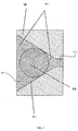
- FIG. 1 shows the section through a stent structure with a marker 3 incorporated therein in accordance with a first exemplary embodiment. It is a wedge-shaped recess formed with a slope 7 in a stent wall 4. In addition, the wedge-shaped recess 5 opens into an opening 2, which forms a passage to an opposite side of the stent structure.
- the recess 5 and the opening 2 can be formed for example by a laser processing of the stent structure.
- a cooled liquid or a fluid is passed through the tubular stent, so that a laser beam passing through the tube wall of the stent is refracted inside the tube.
- a mechanical machining method such as milling, drilling and grinding or eroding can also be used.
- a suitable strip material as a X-ray-visible marker 3 are inserted.
- This strip material has a rectangular or a circular cross-sectional shape.
- the cross section of the strip material is not limited thereto. In particular, it may also have an ellipse shape or a triangular shape, or other polygonal shape.
- the ribbon-like marker 3 abuts the bevels 7 of the wedge shape of the recess 5.
- the marker 3 is self-centering, so that an adjustment of the marker 3 within the recess 5 is superfluous.
- the marker 3 consists for example of tantalum or another radiopaque material.
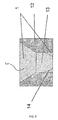
- Fig. 2 shows a second embodiment similar to the first embodiment shown in Fig. 1. The same features of the second embodiment will therefore not be explained again.
- the difference of the second embodiment from the first embodiment is that the opening 2 of the first embodiment is not formed in the second embodiment of FIG. This has the advantage that the polymer material 1 must be introduced only from one side.
- the recess 5 has a substantially rectangular shape with a uniform width B.
- the recess 5 is reduced in its width to a smaller width b in a central region.
- the width b is slightly less than the thickness of the strip material of the marker 3, so that the marker 3 can be clamped in the recess 5. In this way, in turn, an automatic centering of the marker within the stent structure.
- the marker 3 need not have a circular cross-sectional shape, but may also have a rectangular or square or any other shape as long as the sides of the Marker 3, which engage with the walls 8 of the stent structure, are slightly rounded to engage with the recess 5 at the narrowed location with the width b in the press fit.
- the advantage of this embodiment lies in a uniformly acting fixing force of the polymer 1 in both an upward and in a downward direction. Since this embodiment leads to a symmetrical cross-sectional shape of the stent structure, the radiopacity is particularly advantageous pronounced.
- the recess 5 in a central region on a projection 31 and the marker 10 is provided with a recess 11.
- the shape of the projection 31 of the recess 5 is adapted to the shape of the recess 11 of the marker 10 so that the marker 10 can snap into the projection 31 of the recess 5.
- the marker 10 is already fixed in the recess 5 of the stent structure.
- the final fixation is then in turn by introducing a polymer material 1.
- By snapping the marker 10 in the recess 5 is a pre-fixing, so that a fixation of the marker 10 during casting with the polymer material 1 is not necessary.
- the production of the stent with the marker 10 fixed therein can be simplified.
- the cross section of the stent structure of the fourth embodiment has a symmetrical shape, the radiopacity is particularly advantageous.
- the pre-fixing of the fourth embodiment is not limited to the formation of the projection 31 and the recess 11. Any other snap connection between the strip material of the marker 10 and the recess 5 of the stent structure may also be used.
- the strip material 10 may have a projection and the recess 5 a recess.
- a band material having a substantially square cross section is used as a marker 13.
- the square cross section of the marker 13 is provided in a direction of insertion of the marker 13 with a slope 14 for facilitating the insertion of the marker 13.
- the recess 5 of the stent structure is wedge-shaped in an upper region and formed in a lower region with a uniform width.
- the width of the recess 5 is preferably dimensioned slightly smaller than the width of the marker 13, so that a clamping connection between the marker 13 and the recess 5 of the stent structure comes about.
- a residual volume of the recess 5 is in turn potted by a polymer material 1.
- Polytetrafluoroethylene, fluoroethylene propylene, polyvinyl fluoride, polyether urethane, polyester urethane, polycarbonate urethane, silicone, polyphosphazenes, polyphosphoric esters, polyactides, polyanhydrides, polyimide, polyethylene, polypropylene, ethylene vinyl acetate, polyether ketones, polyaryl ether ketones or polysulfones are particularly suitable as a polymer material for all embodiments 1 to 5 described hitherto.
- Tungsten, tantalum, gold, platinum, niobium, palladium, silver, iridium and alloys thereof are particularly suitable as the material for the markers 3, 10, 13.
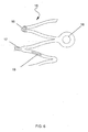
- the recesses 5 within the stent structure may be attached to various locations of a stent. As shown in Fig. 6, the recesses 5 may be attached to a vertex 16, a ridge or cell connector 17 or to a web 19 of a stent structure. In addition, the recesses 5 can be attached to stent ends 18.
- FIG. 7 shows a view AA of FIG. 2.
- the recess 5 has different shapes in the longitudinal direction.
- the recess 5 may have at its ends a region of increased width.
- the width of the recess 5 may vary wavy, so that the marker 3, 6, 13, 20 is clamped to the wave projections of the recess 5.
- the recess 5 may have a sawtooth profile, so that the marker 3, 6, 13, 20 is clamped with the teeth of the recess.
- the recess 5 may have any other shape.
- the marker should only be clamped at spaced apart locations in the longitudinal direction of the stent structure by protrusions of the recess so that pre-fixation can be achieved prior to casting with the polymer 1.
- a zig-zag profile is also suitable for this purpose.
- band material offers the advantage that not only individual sites such as ends of the stent structure can be made visible by the marker, but the entire stent structure can be made visible when the band material extends over a greater length of the webs of a stent structure.
- the invention is not limited to nitinol stents, but may be applied to stents of other materials. Examples include stents made of stainless steel or cobalt-chromium.
- the invention offers the particular advantage that the strip material for the formation of the marker over a marker made of a polymer with X-ray-visible powder has an increased improved radiopacity. Compared with attaching a marker by laser welding and coating the stent structure, the present invention provides a simplified method of attaching a marker to a stent structure.
- the marker is not limited to the tape material described here.
- the marker may have any other shape, such as the shape of a ball, a pin or a cone. All that matters is that a solid of a radiopaque material is placed in a recess of the stent structure and potted with a polymer.
- the recess may have any suitable shape to the solid form, for example a cylindrical shape, a conical shape or a shape with projections and / or depressions to form a snap connection.
Abstract
Description
Die vorliegende Erfindung betrifft einen Stent mit einem Marker zur Verbesserung der Röntgensichtbarkeit des Stents sowie ein Verfahren zum Herstellen eines derartigen Stents.The present invention relates to a stent with a marker for improving the radiopacity of the stent and to a method for producing such a stent.
Stents werden verwendet, um verschieden Kanäle lebender Körper, wie z.B. Blutgefäße, Speiseröhre, Harnröhre, Nierengänge, durch Expandieren einer röhrenförmigen Stentstruktur im Inneren des Kanals gegen Kollabieren oder Verschließen zu schützen und/oder als Träger von Medikamenten in Körperkanälen eine zumindest lokale Therapie zu ermöglichen. Stents können darüber hinaus als Aneurismen-Stents bzw. Endoprothese für intrazelebrale Gefäßaussackungen oder als intraluminaler Stent eingesetzt werden.Stents are used to connect different channels of living bodies, such as e.g. Protect blood vessels, esophagus, urethra, kidney ducts from collapse or occlusion by expanding a tubular stent structure inside the duct and / or to allow at least local therapy as carriers of medicaments in body ducts. In addition, stents can be used as aneurysm stents or endoprosthesis for intracerebral vessel evacuations or as an intraluminal stent.
Der Stent muß radial im Kanal expandierbar sein, um die Kanalwand zu stützen. Darüber hinaus muß der Stent im expandierten Zustand flexibel bzw. schlauchartig sein, um die Stützfunktion auch in gebogenen Kanal- bzw. Aderbereichen zu ermöglichen. Weiterhin muß der Stent auch im komprimierten Zustand flexibel sein, um durch gebogene bzw. kurvige Kanäle und Blutgefäße gelangen zu können.The stent must be radially expandable in the channel to support the channel wall. In addition, the stent in the expanded state must be flexible or hose-like, to allow the support function in curved channel or wire areas. Furthermore, the stent must be flexible even in the compressed state in order to be able to pass through curved or curved channels and blood vessels.
Um dies zu erreichen werden bei bekannten Stents verschiedene funktionale Geometrieelemente als Wandabschnitte zu einer Vielzahl Zellen kombiniert, die aneinander angrenzen. Die einzelnen Wandabschnitte sind in bestimmter Weise, beispielsweise gekrümmt oder gerade, ausgebildet, um dem Stent die gewünschten Deformationseigenschaften zu verleihen. Damit eine radiale Expansion des Stents ermöglicht ist, sind sogenannten Zick-Zack-Strukturen ausgebildet, die durch Brücken verbunden sind. Die Brücken können sich beim Strecken der Zick-Zack-Strukturen verformen bzw. abflachen und ermöglichen so eine tangentenähnliche Biegelinie des Stents.In order to achieve this, in known stents various functional geometric elements are combined as wall sections to form a multiplicity of cells which adjoin one another. The individual wall sections are designed in a specific manner, for example curved or straight, in order to give the stent the desired deformation properties. So that a radial expansion of the stent is made possible, so-called zig-zag structures are formed by Bridges are connected. The bridges may become deformed or flattened as the zigzag structures are stretched, allowing for a tangent-like bending line of the stent.
Stents werden in einen lebenden Körper eingeführt, um ein Gefäß zu stützen oder zu erweitern. Hierzu werden diese Stents in einen Katheter geladen und in das Gefäß eingeführt. Nach der Plazierung in dem Gefäß wird der Stent durch seine Formgedächtniseigenschaften oder mit Hilfe eines Ballonkätheders erweitert. Als Stentmaterial mit geeigneten Formgedächtniseigenschaften eignet sich insbesondere Nitinol (Nickel-Titan-Legierung). Für ballonexpandierbare Stents eignen sich insbesondere Edelstahl und Kobalt-Chrom. Jedoch sind diese Materialien bei einer Röntgenuntersuchung ungenügend sichtbar.Stents are inserted into a living body to support or expand a vessel. For this purpose, these stents are loaded into a catheter and introduced into the vessel. After placement in the vessel, the stent is expanded by its shape memory properties or with the aid of a balloon catheter. Nitinol (nickel-titanium alloy) is particularly suitable as a stent material with suitable shape memory properties. For balloon-expandable stents are particularly stainless steel and cobalt-chromium. However, these materials are insufficiently visible in an X-ray examination.
Deshalb muß ein aus Nitinol, Edelstahl oder Cobalt-Chrom bestehender Stent mit Markern zur Verbesserung der Röntgensichtbarkeit versehen werden.Therefore, a nitinol, stainless steel or cobalt-chromium stent must be provided with markers to improve radiopacity.
US 6,355,058 offenbart hierzu einen Stent mit einer röntgensichtbaren Beschichtung. WO 02/15820 offenbart einen Stent mit Tantalmarkern, die durch Laserschweißen an der Stentstruktur angebracht werden. US 2002/01 93 867 offenbart einen Stent, bei dem ein Markereinsatz aus Tantal in einem Markergehäuse der Stentstruktur eingebettet ist. Schließlich offenbart US 6,635,082 eine Stentstruktur mit Mikrodepots in einer Kegelstumpfform, in die ein röntgensichtbares Metall eingebracht wird, das in einer Polymerlösung suspendiert ist.US Pat. No. 6,355,058 discloses a stent with a radiopaque coating for this purpose. WO 02/15820 discloses a stent with tantalum markers which are laser welded to the stent structure. US 2002/01 93 867 discloses a stent in which a tantalum marker insert is embedded in a marker housing of the stent structure. Finally, US Pat. No. 6,635,082 discloses a stent structure with microdeposits in a truncated cone shape into which is introduced a radiopaque metal suspended in a polymer solution.
Die Aufgabe der Erfindung besteht in der Schaffung eines Stents mit einer verbesserten Röntgensichtbarkeit sowie eines Herstellverfahrens eines derartigen Stents.The object of the invention is to provide a stent with improved radiopacity and a production method of such a stent.
Diese Aufgabe wird durch einen Stent nach Anspruch 1 und ein Verfahren nach Anspruch 10 gelöst. Vorteilhafte Weiterbildungen der Erfindung sind in den abhängigen Ansprüchen angeführt.This object is achieved by a stent according to
Die Erfindung schafft einen Stent zum Implantieren in einen lebenden Körper mit einem röntgensichtbaren Marker, der in einer Ausnehmung der Stentstruktur aufgenommen ist und wobei ein Restvolumen der Ausnehmung mit einem Polymer aufgefüllt ist.The invention provides a stent for implantation in a living body having a radiopaque marker received in a recess of the stent structure, and wherein a residual volume of the recess is filled with a polymer.
Indem ein röntgensichtbarer Marker aus einem Bandmaterial bzw. einem Draht an dem Stent angebracht wird, ist die Röntgensichtbarkeit verbessert. Indem des weiteren ein Restvolumen der Ausnehmung der Stentstruktur mit einem Polymer aufgefüllt wird, wird der Marker auf einfache Weise an der Stentstruktur fixiert. Der Marker kann dabei aus einem Bandmaterial mit rechteckigem Querschnitt oder einem Bandmaterial mit kreisrundem Querschnitt bzw. einem Draht gebildet werden. Dieser Draht bzw. das Band hat eine hohe Röntgensichtbarkeit.By attaching an X-ray visible marker of a ribbon or wire to the stent, the radiopacity is improved. Further, by filling a residual volume of the recess of the stent structure with a polymer, the marker is easily fixed to the stent structure. The marker can be formed from a strip material with a rectangular cross section or a strip material with a circular cross section or a wire. This wire or tape has a high radiopacity.
Vorzugsweise hat der Marker einen kreisrunden Querschnitt und die Ausnehmung der Stentstruktur eine Keilform, so dass der Marker sich in der Ausnehmung selbsttätig zentriert.Preferably, the marker has a circular cross-section and the recess of the stent structure has a wedge shape, so that the marker is automatically centered in the recess.
Indem der Marker einen kreisrunden Querschnitt aufweist und die Ausnehmung der Struktur eine Keilform aufweist, kann sich der Marker aufgrund seiner Schwerkraft selbsttätig in der Ausnehmung an den Schrägen der Keilform zentrieren. Eine Justierung des Markers in der Ausnehmung ist deshalb nicht nötig.Because the marker has a circular cross-section and the recess of the structure has a wedge shape, the marker can, due to its gravity, automatically center in the recess on the bevels of the wedge shape. An adjustment of the marker in the recess is therefore not necessary.
Vorzugsweise mündet die keilförmige Ausnehmung in eine Öffnung, die einen Durchlass nach einer entgegengesetzten Seite der Stentstruktur aufweist.Preferably, the wedge-shaped recess opens into an opening having a passage to an opposite side of the stent structure.
Indem die keilförmige Ausnehmung in eine Öffnung mündet mit einem Durchlaß nach einer entgegengesetzten Seite der Stentstruktur, kann überschüssiges Polymer beim Vergießen des Markers abfließen.By the wedge-shaped recess opens into an opening with a passage to an opposite side of the stent structure, excess polymer can flow during the casting of the marker.
Vorzugsweise hat die Ausnehmung eine im wesentlichen gleichmäßige Breite sowie einen Bereich mit verringerter Breite zum Klemmen des Markers.Preferably, the recess has a substantially uniform width and an area of reduced width for clamping the marker.
Vorzugsweise hat entweder die Ausnehmung oder der Marker einen Vorsprung und das andere Element aus der Ausnehmung und dem Marker eine Vertiefung für eine Schnappverbindung des Markers in der Ausnehmung.Preferably, either the recess or the marker has a projection and the other element of the recess and the marker has a recess for a snap connection of the marker in the recess.
Vorzugsweise ist der Marker stangenförmig ausgebildet und Seitenwände der Ausnehmung weisen in einer Längsrichtung eine Vielzahl an Vorsprüngen zum Klemmen des Markers auf. Die Vorsprünge sind vorzugweise wellenförmig angeordnet.Preferably, the marker is bar-shaped and side walls of the recess have a plurality of projections for clamping the marker in a longitudinal direction. The projections are preferably arranged wave-shaped.
Indem der Marker in der Ausnehmung geklemmt wird bzw. über eine Schnappverbindung mit dieser in Eingriff tritt, wird der Marker selbsttätig in der Ausnehmung justiert. Ein Schritt des Justierens des Markers in der Ausnehmung bei der Herstellung des Stents kann somit entfallen. Hierdurch können die Herstellkosten aufgrund der vereinfachten Fertigung reduziert werden.By the marker is clamped in the recess or via a snap connection with this engages, the marker is automatically adjusted in the recess. A step of adjusting the marker in the recess in the production of the stent can thus be omitted. As a result, the manufacturing costs can be reduced due to the simplified production.
Des weiteren schafft die vorliegende Erfindung ein Verfahren zur Verbesserung der Röntgensichtbarkeit eines Stents mit den Schritten: Bilden einer Ausnehmung in der Stentstruktur; Einsetzen eines Markers in die Ausnehmung; und Auffüllen der Ausnehmung mit einem Polymer.Furthermore, the present invention provides a method for improving the radiopacity of a stent comprising the steps of: forming a recess in the stent structure; Inserting a marker into the recess; and filling the recess with a polymer.
Vorzugsweise weist dieses Verfahren noch den Schritt des Bildens einer Klemm- oder Schnappverbindung des Markers in der Ausnehmung auf.Preferably, this method still has the step of forming a clamping or snap connection of the marker in the recess.
Die Erfindung wird unter Bezugnahme auf die Zeichnungen nachfolgend näher erläutert.
- Fig. 1 zeigt einen Schnitt durch eine Stentstruktur mit einem darin aufgenommenen Marker gemäß einem ersten Ausführungsbeispiel.
- Fig. 2 zeigt einen Schnitt durch eine erfindungsgemäße Stentstruktur mit einem darin aufgenommenen Marker gemäß einem zweiten Ausführungsbeispiel.
- Fig. 3 zeigt einen Schnitt durch eine erfindungsgemäße Stentstruktur mit einem darin aufgenommenen Marker gemäß einem dritten Ausführungsbeispiel.
- Fig. 4 zeigt einen Schnitt durch eine erfindungsgemäße Stentstruktur mit einem darin aufgenommenen Marker gemäß einem vierten Ausführungsbeispiel.
- Fig. 5 zeigt einen Schnitt durch eine erfindungsgemäße Stentstruktur mit einem darin aufgenommenen Marker gemäß einem fünften Ausführungsbeispiel.
- Fig. 6 zeigt eine erfindungsgemäße Stentstruktur mit an unterschiedlichen Stellen der Stentstruktur angeordneten Markern.
- Fig. 7a bis c zeigen eine Ansicht A-A von Fig. 2 von unterschiedlichen. Stentstrukturen zur Aufnahme eines Markers.
- 1 shows a section through a stent structure with a marker received therein according to a first exemplary embodiment.
- 2 shows a section through a stent structure according to the invention with a marker received therein according to a second exemplary embodiment.
- 3 shows a section through a stent structure according to the invention with a marker received therein according to a third exemplary embodiment.
- 4 shows a section through a stent structure according to the invention with a marker received therein according to a fourth exemplary embodiment.
- 5 shows a section through a stent structure according to the invention with a marker received therein according to a fifth exemplary embodiment.
- FIG. 6 shows a stent structure according to the invention with markers arranged at different points of the stent structure.
- Figs. 7a to c show a view AA of Fig. 2 of different. Stent structures for receiving a marker.
Die Erfindung wird nachfolgend anhand bevorzugter Ausführungsbeispiele näher erläutert. Fig. 1 zeigt den Schnitt durch eine Stentstruktur mit einem darin eingelagerten Marker 3 gemäß einem ersten Ausführungsbeispiel. Es ist eine keilförmige Ausnehmung mit einer Schräge 7 in einer Stentwand 4 ausgeformt. Darüber hinaus mündet die keilförmige Ausnehmung 5 in einer Öffnung 2, die einen Durchlaß zu einer entgegengesetzten Seite der Stentstruktur bildet.The invention will be explained in more detail below with reference to preferred embodiments. 1 shows the section through a stent structure with a
Die Ausnehmung 5 sowie die Öffnung 2 können beispielsweise durch eine Laserbearbeitung der Stentstruktur gebildet werden. Vorzugsweise wird dabei eine gekühlte Flüssigkeit oder ein Fluid durch den rohrförmigen Stent hindurchgeleitet, so dass ein durch die Rohrwandung des Stents hindurchtretender Laserstrahl im Inneren des Rohrs refraktiert wird. Es kann jedoch auch ein mechanisches Bearbeitungsverfahren, wie Fräsen, Bohren und Schleifen oder Erodieren zum Einsatz kommen.The
In diese keilförmige Ausnehmung 5 kann eine geeignetes Bandmaterial als ein röntgensichtbarer Marker 3 eingelegt werden. Dieses Bandmaterial hat einen rechteckige oder eine kreisrunde Querschnittsform. Jedoch ist der Querschnitt des Bandmaterials nicht hierauf beschränkt. Insbesondere kann es auch eine Elipsenform oder eine Dreiecksform, oder andere Polygonform haben. Wie in Fig. 1 gezeigt ist, liegt der bandartige Marker 3 an den Schrägen 7 der Keilform der Ausnehmung 5 an. Hierdurch zentriert sich der Marker 3 selbsttätig, so daß eine Justierung des Markers 3 innerhalb der Ausnehmung 5 überflüssig ist. Der Marker 3 besteht beispielsweise aus Tantal oder einem anderen röntgensichtbaren Material.In this wedge-shaped
Nach dem Einlegen des Markers 3 in die Ausnehmung 5 wird ein Restvolumen der Ausnehmung 5 mit einem Polymer 1 gefüllt, wodurch der Marker 3 in der Ausnehmung 5 fixiert wird. Überschüssiges Polymer 1 kann dabei über die Öffnung 2 zu der entgegengesetzten Seite der Stentstruktur abfließen.After inserting the
Fig. 2 zeigt ein zweites Ausführungsbeispiel ähnlich dem ersten Ausführungsbeispiel, das in Fig. 1 gezeigt ist. Gleiche Merkmale des zweiten Ausführungsbeispiels werden deshalb nicht nochmals erläutert. Der Unterschied des zweiten Ausführungsbeispiels zu dem ersten Ausführungsbeispiel besteht darin, daß die Öffnung 2 des ersten Ausführungsbeispiels in dem zweitem Ausführungsbeispiel von Fig. 2 nicht ausgebildet ist. Hierdurch ergibt sich der Vorteil, daß das Polymermaterial 1 nur von einer Seite eingebracht werden muß.Fig. 2 shows a second embodiment similar to the first embodiment shown in Fig. 1. The same features of the second embodiment will therefore not be explained again. The difference of the second embodiment from the first embodiment is that the opening 2 of the first embodiment is not formed in the second embodiment of FIG. This has the advantage that the
Unter Bezugnahme auf Fig. 3 wird ein drittes Ausführungsbeispiel der vorliegenden Erfindung erläutert. Bei diesem Ausführungsbeispiel hat die Ausnehmung 5 im wesentlichen eine rechteckige Form mit gleichmäßiger Breite B. Darüber hinaus ist die Ausnehmung 5 in einem zentralen Bereich in ihrer Breite auf eine geringere Breite b verringert. Die Breite b ist dabei etwas geringer als die Dicke des Bandmaterials des Markers 3, so daß der Marker 3 in der Ausnehmung 5 festgeklemmt werden kann. Hierdurch erfolgt wiederum eine selbsttätige Zentrierung des Markers innerhalb der Stentstruktur. Der Marker 3 muß hierbei keine kreisförmige Querschnittsform haben, sondern kann auch eine rechteckige oder quadratische oder beliebige andere Form haben, solange wie die Seiten des Markers 3, die mit den Wänden 8 der Stentstruktur in Eingriff treten, etwas abgerundet sind, um mit der Ausnehmung 5 an der verengten Stelle mit der Breite b im Klemmsitz in Eingriff zu treten. Der Vorteil dieses Ausführungsbeispiels liegt in einer gleichmäßig wirkenden Fixierkraft des Polymers 1 sowohl in einer Aufwärts- als auch in einer Abwärtsrichtung. Da diese Ausführungsform zu einer symmetrischen Querschnittsform der Stentstruktur führt, ist die Röntgensichtbarkeit besonders vorteilhaft ausgeprägt.Referring to Fig. 3, a third embodiment of the present invention will be explained. In this embodiment, the
Unter Bezugnahme auf Fig. 4 wird ein viertes bevorzugtes Ausführungsbeispiel erläutert. Bei diesem Ausführungsbeispiel weist die Ausnehmung 5 in einem zentralen Bereich einen Vorsprung 31 auf und der Marker 10 ist mit einer Vertiefung 11 versehen. Die Form des Vorsprungs 31 der Ausnehmung 5 ist so an die Form der Vertiefung 11 des Markers 10 angepaßt, daß der Marker 10 in den Vorsprung 31 der Ausnehmung 5 einschnappen kann. Hierdurch wird der Marker 10 bereits in der Ausnehmung 5 der Stentstruktur fixiert. Die endgültige Fixierung erfolgt dann wiederum durch Einbringen eines Polymermaterials 1. Durch das Einschnappen des Markers 10 in der Ausnehmung 5 erfolgt eine Vor-Fixierung, so daß eine Fixierung des Markers 10 während dem Vergießen mit dem Polymermaterial 1 nicht notwendig ist. Hierdurch kann die Herstellung des Stents mit dem darin fixierten Marker 10 vereinfacht werden. Da der Querschnitt der Stentstruktur des vierten Ausführungsbeispiels darüber hinaus eine symmetrische Form hat, ist die Röntgensichtbarkeit besonders vorteilhaft.Referring to Fig. 4, a fourth preferred embodiment will be explained. In this embodiment, the
Die Vor-Fixierung des vierten Ausführungsbeispiels ist jedoch nicht auf die Ausbildung des Vorsprungs 31 und die Vertiefung 11 beschränkt. Es kann auch jede andere Einschnappverbindung zwischen dem Bandmaterial des Markers 10 und der Ausnehmung 5 der Stentstruktur zur Anwendung kommen. Beispielsweise kann das Bandmaterial 10 einen Vorsprung haben und die Ausnehmung 5 eine Vertiefung.However, the pre-fixing of the fourth embodiment is not limited to the formation of the
Unter Bezugnahme auf Fig. 5 wird ein fünftes Ausführungsbeispiel der vorliegenden Erfindung erläutert. Bei diesem Ausführungsbeispiel wird ein Bandmaterial mit einem im wesentlichen quadratischen Querschnitt als ein Marker 13 verwendet. Der quadratische Querschnitt des Markers 13 ist jedoch in einer Einsetzrichtung des Markers 13 mit einer Schräge 14 zum Erleichtern des Einsetzens des Markers 13 versehen. Darüber hinaus ist die Ausnehmung 5 der Stentstruktur in einem oberen Bereich keilförmig ausgebildet und in einem unteren Bereich mit gleichmäßiger Breite ausgebildet. Die Breite der Ausnehmung 5 ist dabei vorzugsweise geringfügig kleiner dimensioniert als die Breite des Markers 13, so daß eine Klemmverbindung zwischem dem Marker 13 und der Ausnehmung 5 der Stentstruktur zustande kommt. Ein Restvolumen der Ausnehmung 5 wird wiederum- durch ein Polymermaterial 1 vergossen.Referring to Fig. 5, a fifth embodiment of the present invention will be explained. In this embodiment, a band material having a substantially square cross section is used as a
Als ein Polymermaterial für alle bisher beschriebenen Ausführungsbeispiele 1 bis 5 eignet sich insbesondere Polytetrafluorethylen, Fluorethylenpropylen, Polyvinylfluorid, Polyetherurethan, Polyesterurethan, Polycarbonaturethan, Silikon, Polyphosphazene, Polyphosphorester, Polyactide, Polyanhydride, Polyimid, Polyethylen, Polypropylen, Ethylenvinylacetat, Polyetherketone, Polyaryletherketone oder Polysulfone. Als das Material für den Marker 3, 10, 13 eignet sich insbesondere Wolfram, Tantal, Gold, Platin, Niob, Palladium, Silber, Iridium sowie Legierungen hiervon.Polytetrafluoroethylene, fluoroethylene propylene, polyvinyl fluoride, polyether urethane, polyester urethane, polycarbonate urethane, silicone, polyphosphazenes, polyphosphoric esters, polyactides, polyanhydrides, polyimide, polyethylene, polypropylene, ethylene vinyl acetate, polyether ketones, polyaryl ether ketones or polysulfones are particularly suitable as a polymer material for all
Die Ausnehmungen 5 innerhalb der Stentstruktur können an verschiedenen Stellen eines Stents angebracht werden. Wie in Fig. 6 gezeigt ist, können die Ausnehmungen 5 an einem Scheitelpunkt 16, einem Steg oder Zellenverbinder 17 oder an einem Steg 19 einer Stentstruktur angebracht werden. Darüber hinaus können die Ausnehmungen 5 an Stentenden 18 angebracht werden.The
Fig. 7 zeigt eine Ansicht A-A von Fig. 2. Gemäß Fig. 7a bis c hat die Ausnehmung 5 in der Längsrichtung unterschiedliche Formen. Wie in Fig. 7a gezeigt ist, kann die Ausnehmung 5 an ihren Enden einen Bereich mit vergrößerter Breite aufweisen. Wie in Fig. 7b gezeigt ist, kann die Breite der Ausnehmung 5 wellenförmig variieren, so daß der Marker 3, 6, 13, 20 an den Wellenerhebungen der Ausnehmung 5 geklemmt wird. Wie in Fig. 7c gezeigt ist, kann die Ausnehmung 5 ein Sägezahnprofil haben, so daß der Marker 3, 6, 13, 20 mit den Zähnen der Ausnehmung geklemmt wird. Die Erfindung ist jedoch nicht auf die hier gezeigten Beispiele beschränkt. Die Ausnehmung 5 kann jede andere Form haben. Der Marker sollte lediglich an voneinander beabstandeten Stellen in der Längsrichtung der Stentstruktur durch Vorsprünge der Ausnehmung geklemmt werden, so daß eine Vor-Fixierung vor dem Vergießen mit dem Polymer 1 erzielt werden kann. Hierzu eignet sich insbesondere auch ein Zick-Zack-Profil.FIG. 7 shows a view AA of FIG. 2. According to FIGS. 7a to c, the
Der Einsatz eines Bandmaterials bietet den Vorteil, dass nicht nur einzelne Stellen wie Enden der Stentstruktur durch den Marker sichtbar gemacht werden können, sondern die gesamte Stentstruktur sichtbar gemacht werden kann, wenn sich das Bandmaterial über eine größere Länge der Stege einer Stentstruktur erstreckt.The use of a band material offers the advantage that not only individual sites such as ends of the stent structure can be made visible by the marker, but the entire stent structure can be made visible when the band material extends over a greater length of the webs of a stent structure.
Die Erfindung ist auch nicht auf Stents aus Nitinol beschränkt, sondern kann auf Stents aus anderen Materialien angewandt werden. Beispiels hierfür sind Stents aus Edelstahl oder Kobalt-Chrom. Die Erfindung bietet insbesondere den Vorteil, daß das Bandmaterial für die Ausbildung des Markers gegenüber einem Marker aus einem Polymer mit röntgensichtbarem Pulver eine erhöhte verbesserte Röntgensichtbarkeit aufweist. Gegenüber dem Anbringen eines Markers mittels Laserschweißen und Beschichten der Stentstruktur bietet die vorliegende Erfindung ein vereinfachtes Verfahren zum Anbringen eines Markers an einer Stentstruktur.The invention is not limited to nitinol stents, but may be applied to stents of other materials. Examples include stents made of stainless steel or cobalt-chromium. The invention offers the particular advantage that the strip material for the formation of the marker over a marker made of a polymer with X-ray-visible powder has an increased improved radiopacity. Compared with attaching a marker by laser welding and coating the stent structure, the present invention provides a simplified method of attaching a marker to a stent structure.
Der Marker ist jedoch nicht auf das hier beschriebene Bandmaterial beschränkt. Der Marker kann jede beliebige andere Form haben, beispielsweise die Form einer Kugel, eines Stifts oder eines Kegels. Es kommt lediglich darauf an, dass ein Festkörper aus einem röntgensichtbaren Material in einer Ausnehmung der Stentstruktur plaziert wird und mit einem Polymer vergossen wird.However, the marker is not limited to the tape material described here. The marker may have any other shape, such as the shape of a ball, a pin or a cone. All that matters is that a solid of a radiopaque material is placed in a recess of the stent structure and potted with a polymer.
Vorteilhaft ist dabei ein Klemmsitz oder eine Schnappverbindung des Festkörpers innerhalb der Ausnehmung. Hierzu kann die Ausnehmung jede beliebige zu der Festkörperform passende Form haben, beispielsweise eine zylindrische Form, eine konische Form oder eine Form mit Vorsprüngen und/oder Vertiefungen zum Bilden einer Schnappverbindung.A clamping seat or a snap connection of the solid within the recess is advantageous. For this purpose, the recess may have any suitable shape to the solid form, for example a cylindrical shape, a conical shape or a shape with projections and / or depressions to form a snap connection.
- 11
- Polymerpolymer
- 22
- Öffnungopening
- 33
- Markermarker
- 44
- Stentwandstent wall
- 55
- Ausnehmungrecess
- 66
- Stentwandstent wall
- 77
- Schrägeslope
- 88th
- Stentwandstent wall
- 99
- Stentwandstent wall
- 1010
- Markermarker
- 1111
- Vertiefungdeepening
- 1212
- Stentwandstent wall
- 1313
- Markermarker
- 1414
- Schrägeslope
- 1515
- Stentstrukturstent structure
- 1616
- Markermarker
- 1717
- Markermarker
- 1818
- Markermarker
- 1919
- Markermarker
- 2020
- Markermarker
- 3131
- Vorsprunghead Start
Claims (11)
Applications Claiming Priority (1)
| Application Number | Priority Date | Filing Date | Title |
|---|---|---|---|
| DE102004054084A DE102004054084B4 (en) | 2004-11-09 | 2004-11-09 | Stent with a marker for improving the radiopacity, the use and a method for producing such a stent |
Publications (2)
| Publication Number | Publication Date |
|---|---|
| EP1656905A1 true EP1656905A1 (en) | 2006-05-17 |
| EP1656905B1 EP1656905B1 (en) | 2006-12-27 |
Family
ID=35431529
Family Applications (1)
| Application Number | Title | Priority Date | Filing Date |
|---|---|---|---|
| EP05019459A Active EP1656905B1 (en) | 2004-11-09 | 2005-09-07 | Method for attaching radiopaque markers to a stent |
Country Status (3)
| Country | Link |
|---|---|
| EP (1) | EP1656905B1 (en) |
| AT (1) | ATE349189T1 (en) |
| DE (2) | DE102004054084B4 (en) |
Cited By (11)
| Publication number | Priority date | Publication date | Assignee | Title |
|---|---|---|---|---|
| WO2007081551A1 (en) * | 2006-01-04 | 2007-07-19 | Abbot Cardiovascular Systems Inc. | Stents with radiopaque markers |
| WO2008036380A1 (en) | 2006-09-21 | 2008-03-27 | Boston Scientific Limited | Stent with support element |
| FR2957240A1 (en) * | 2010-03-10 | 2011-09-16 | Philippe Laheurte | Medical device i.e. surgical tray, for receiving set of associated elements e.g. basket, has blocking unit cooperating with retaining portion of cavity to prevent withdrawn of insert outside of cavity in blocking position of blocking unit |
| EP2881088A1 (en) * | 2013-12-04 | 2015-06-10 | Admedes Schuessler GmbH | Implant comprising a marker element |
| US9694116B2 (en) | 2006-05-26 | 2017-07-04 | Abbott Cardiovascular Systems Inc. | Stents with radiopaque markers |
| US9737368B2 (en) | 2015-02-24 | 2017-08-22 | Abbott Cardiovascular Systems Inc. | System and method for attaching a radiopaque marker bead to an endoprosthesis |
| US9763818B2 (en) | 2010-01-30 | 2017-09-19 | Abbott Cardiovascular Systems Inc. | Method of crimping stent on catheter delivery assembly |
| US9827119B2 (en) | 2010-01-30 | 2017-11-28 | Abbott Cardiovascular Systems Inc. | Polymer scaffolds having a low crossing profile |
| US9999527B2 (en) | 2015-02-11 | 2018-06-19 | Abbott Cardiovascular Systems Inc. | Scaffolds having radiopaque markers |
| US10307274B2 (en) | 2011-07-29 | 2019-06-04 | Abbott Cardiovascular Systems Inc. | Methods for uniform crimping and deployment of a polymer scaffold |
| US10610387B2 (en) | 2015-06-12 | 2020-04-07 | Abbott Cardiovascular Systems Inc. | Scaffolds having a radiopaque marker and methods for attaching a marker to a scaffold |
Families Citing this family (4)
| Publication number | Priority date | Publication date | Assignee | Title |
|---|---|---|---|---|
| DE102007031796A1 (en) * | 2007-07-07 | 2009-01-08 | WRW Consulting GbR (Vertretungsberechtigter Gesellschafter: Dr. Walter Reith, 66424 Homburg) | Radially expandable system for use in body tubes |
| DE102010021962A1 (en) * | 2010-05-28 | 2011-12-01 | Siemens Aktiengesellschaft | Medical implant for e.g. transplantation of tissue during surgery, has recesses forming geometrical pattern for determining location and position of implant based on two-dimensional X-ray images and independent of fluoroscopy direction |
| DE102012107261B4 (en) * | 2012-08-08 | 2015-11-12 | Acandis Gmbh & Co. Kg | Medical device for import into a living body and method of manufacturing such a device |
| US11147694B1 (en) | 2021-03-26 | 2021-10-19 | Vesper Medical, Inc. | Medical implants with structural members having barbs for retaining radiopaque markers |
Citations (6)
| Publication number | Priority date | Publication date | Assignee | Title |
|---|---|---|---|---|
| US6293966B1 (en) * | 1997-05-06 | 2001-09-25 | Cook Incorporated | Surgical stent featuring radiopaque markers |
| WO2002026162A2 (en) * | 2000-09-26 | 2002-04-04 | Advanced Cardiovascular Systems, Inc. | A method of loading a substance onto an implantable device |
| DE10064596A1 (en) * | 2000-12-18 | 2002-06-20 | Biotronik Mess & Therapieg | Application of a marker element to an implant, especially a stent, comprises introducing a solidifiable material into a recess and solidifying the material in the recess |
| WO2003015664A1 (en) * | 2001-08-20 | 2003-02-27 | Conor Medsystems, Inc. | Expandable medical device for delivery of beneficial agent |
| US20040088039A1 (en) * | 2002-11-01 | 2004-05-06 | Lee Nathan T. | Method of securing radiopaque markers to an implant |
| DE202004014789U1 (en) * | 2004-09-22 | 2005-01-27 | Campus Medizin & Technik Gmbh | Stent for implantation into or onto a hollow organ comprises a cutout serving as receptacle for a conical marker element which is X-ray opaque and is oriented radially relative to the stent axis |
Family Cites Families (4)
| Publication number | Priority date | Publication date | Assignee | Title |
|---|---|---|---|---|
| US6022374A (en) * | 1997-12-16 | 2000-02-08 | Cardiovasc, Inc. | Expandable stent having radiopaque marker and method |
| US6585765B1 (en) * | 2000-06-29 | 2003-07-01 | Advanced Cardiovascular Systems, Inc. | Implantable device having substances impregnated therein and a method of impregnating the same |
| US6863685B2 (en) * | 2001-03-29 | 2005-03-08 | Cordis Corporation | Radiopacity intraluminal medical device |
| US6945995B2 (en) * | 2002-08-29 | 2005-09-20 | Boston Scientific Scimed, Inc. | Stent overlap point markers |
-
2004
- 2004-11-09 DE DE102004054084A patent/DE102004054084B4/en active Active
-
2005
- 2005-09-07 EP EP05019459A patent/EP1656905B1/en active Active
- 2005-09-07 AT AT05019459T patent/ATE349189T1/en active
- 2005-09-07 DE DE502005000264T patent/DE502005000264D1/en active Active
Patent Citations (6)
| Publication number | Priority date | Publication date | Assignee | Title |
|---|---|---|---|---|
| US6293966B1 (en) * | 1997-05-06 | 2001-09-25 | Cook Incorporated | Surgical stent featuring radiopaque markers |
| WO2002026162A2 (en) * | 2000-09-26 | 2002-04-04 | Advanced Cardiovascular Systems, Inc. | A method of loading a substance onto an implantable device |
| DE10064596A1 (en) * | 2000-12-18 | 2002-06-20 | Biotronik Mess & Therapieg | Application of a marker element to an implant, especially a stent, comprises introducing a solidifiable material into a recess and solidifying the material in the recess |
| WO2003015664A1 (en) * | 2001-08-20 | 2003-02-27 | Conor Medsystems, Inc. | Expandable medical device for delivery of beneficial agent |
| US20040088039A1 (en) * | 2002-11-01 | 2004-05-06 | Lee Nathan T. | Method of securing radiopaque markers to an implant |
| DE202004014789U1 (en) * | 2004-09-22 | 2005-01-27 | Campus Medizin & Technik Gmbh | Stent for implantation into or onto a hollow organ comprises a cutout serving as receptacle for a conical marker element which is X-ray opaque and is oriented radially relative to the stent axis |
Cited By (18)
| Publication number | Priority date | Publication date | Assignee | Title |
|---|---|---|---|---|
| US10070975B2 (en) | 2006-01-04 | 2018-09-11 | Abbott Cardiovascular Systems Inc. | Stents with radiopaque markers |
| WO2007081551A1 (en) * | 2006-01-04 | 2007-07-19 | Abbot Cardiovascular Systems Inc. | Stents with radiopaque markers |
| US9694116B2 (en) | 2006-05-26 | 2017-07-04 | Abbott Cardiovascular Systems Inc. | Stents with radiopaque markers |
| WO2008036380A1 (en) | 2006-09-21 | 2008-03-27 | Boston Scientific Limited | Stent with support element |
| US7875069B2 (en) | 2006-09-21 | 2011-01-25 | Boston Scientific Scimed, Inc. | Stent with support element |
| US9770351B2 (en) | 2010-01-30 | 2017-09-26 | Abbott Cardiovascular Systems Inc. | Crush recoverable polymer scaffolds |
| US9763818B2 (en) | 2010-01-30 | 2017-09-19 | Abbott Cardiovascular Systems Inc. | Method of crimping stent on catheter delivery assembly |
| US9827119B2 (en) | 2010-01-30 | 2017-11-28 | Abbott Cardiovascular Systems Inc. | Polymer scaffolds having a low crossing profile |
| US9867728B2 (en) | 2010-01-30 | 2018-01-16 | Abbott Cardiovascular Systems Inc. | Method of making a stent |
| US10123894B2 (en) | 2010-01-30 | 2018-11-13 | Abbott Cardiovascular Systems Inc. | Method of crimping stent on catheter delivery assembly |
| US11324614B2 (en) | 2010-01-30 | 2022-05-10 | Abbott Cardiovascular Systems Inc. | Balloon expanded polymer stent |
| FR2957240A1 (en) * | 2010-03-10 | 2011-09-16 | Philippe Laheurte | Medical device i.e. surgical tray, for receiving set of associated elements e.g. basket, has blocking unit cooperating with retaining portion of cavity to prevent withdrawn of insert outside of cavity in blocking position of blocking unit |
| US10307274B2 (en) | 2011-07-29 | 2019-06-04 | Abbott Cardiovascular Systems Inc. | Methods for uniform crimping and deployment of a polymer scaffold |
| EP2881088A1 (en) * | 2013-12-04 | 2015-06-10 | Admedes Schuessler GmbH | Implant comprising a marker element |
| US9999527B2 (en) | 2015-02-11 | 2018-06-19 | Abbott Cardiovascular Systems Inc. | Scaffolds having radiopaque markers |
| US9737368B2 (en) | 2015-02-24 | 2017-08-22 | Abbott Cardiovascular Systems Inc. | System and method for attaching a radiopaque marker bead to an endoprosthesis |
| US10610387B2 (en) | 2015-06-12 | 2020-04-07 | Abbott Cardiovascular Systems Inc. | Scaffolds having a radiopaque marker and methods for attaching a marker to a scaffold |
| US11478370B2 (en) | 2015-06-12 | 2022-10-25 | Abbott Cardiovascular Systems Inc. | Scaffolds having a radiopaque marker and methods for attaching a marker to a scaffold |
Also Published As
| Publication number | Publication date |
|---|---|
| EP1656905B1 (en) | 2006-12-27 |
| DE102004054084B4 (en) | 2007-08-02 |
| DE102004054084A1 (en) | 2006-05-11 |
| ATE349189T1 (en) | 2007-01-15 |
| DE502005000264D1 (en) | 2007-02-08 |
Similar Documents
| Publication | Publication Date | Title |
|---|---|---|
| EP1656905B1 (en) | Method for attaching radiopaque markers to a stent | |
| DE69731514T2 (en) | Expandable stent | |
| DE102005039136B4 (en) | Improving the radiopacity and corrosion resistance of NiTi stents using sandwiched rivets | |
| DE69732992T2 (en) | Stent with variable properties for support optimization | |
| EP1023008B1 (en) | Expanded spreader and a method for producing the same | |
| DE69732229T2 (en) | Stent and manufacturing process for it | |
| DE602004009994T2 (en) | Stent with an attached marker in the form of a sleeve | |
| DE69630379T2 (en) | ENDOVASCULAR BRANCHED STENT | |
| DE60101046T2 (en) | STENT MATRIX | |
| EP2134302B1 (en) | Implant for influencing blood flow | |
| DE60031490T2 (en) | Stents for angioplasty | |
| DE69738023T2 (en) | INTRAVASCULAR STENT | |
| DE69934244T2 (en) | SPIRAL STONE | |
| DE69831575T2 (en) | STENT WITH VARIABLE SPREAD POWER | |
| EP2257248B1 (en) | Stent and method for the production of such a stent | |
| DE102004045994A1 (en) | Stent for implantation in or around a hollow organ with marker elements made from a radiopaque material | |
| DE102018131269B4 (en) | Medical device for insertion into a hollow body organ and manufacturing process | |
| DE10317241A1 (en) | stent | |
| DE202004014789U1 (en) | Stent for implantation into or onto a hollow organ comprises a cutout serving as receptacle for a conical marker element which is X-ray opaque and is oriented radially relative to the stent axis | |
| EP1844740B1 (en) | Self-expanding stent with spring structure | |
| DE102010046408B4 (en) | feed | |
| DE102018133345B4 (en) | Stent | |
| DE102011115238B4 (en) | A body implant with improved radiopacity, combination of a catheter, a guide wire, and a body implant and method for increasing the radiopacity of a body implant | |
| DE102012109736A1 (en) | Medical, intravascularly insertable device e.g. stent, has marker element having a ridge made of second material having higher radiopacity than first material and groove-like recess whose inner contour corresponds to web outer contour | |
| DE102013113271B4 (en) | Medical implant, treatment system with such an implant and method for producing an implant |
Legal Events
| Date | Code | Title | Description |
|---|---|---|---|
| PUAI | Public reference made under article 153(3) epc to a published international application that has entered the european phase |
Free format text: ORIGINAL CODE: 0009012 |
|
| 17P | Request for examination filed |
Effective date: 20060216 |
|
| AK | Designated contracting states |
Kind code of ref document: A1 Designated state(s): AT BE BG CH CY CZ DE DK EE ES FI FR GB GR HU IE IS IT LI LT LU LV MC NL PL PT RO SE SI SK TR |
|
| AX | Request for extension of the european patent |
Extension state: AL BA HR MK YU |
|
| GRAP | Despatch of communication of intention to grant a patent |
Free format text: ORIGINAL CODE: EPIDOSNIGR1 |
|
| GRAS | Grant fee paid |
Free format text: ORIGINAL CODE: EPIDOSNIGR3 |
|
| GRAA | (expected) grant |
Free format text: ORIGINAL CODE: 0009210 |
|
| AK | Designated contracting states |
Kind code of ref document: B1 Designated state(s): AT BE BG CH CY CZ DE DK EE ES FI FR GB GR HU IE IS IT LI LT LU LV MC NL PL PT RO SE SI SK TR |
|
| PG25 | Lapsed in a contracting state [announced via postgrant information from national office to epo] |
Ref country code: CZ Free format text: LAPSE BECAUSE OF FAILURE TO SUBMIT A TRANSLATION OF THE DESCRIPTION OR TO PAY THE FEE WITHIN THE PRESCRIBED TIME-LIMIT Effective date: 20061227 Ref country code: LT Free format text: LAPSE BECAUSE OF FAILURE TO SUBMIT A TRANSLATION OF THE DESCRIPTION OR TO PAY THE FEE WITHIN THE PRESCRIBED TIME-LIMIT Effective date: 20061227 Ref country code: DK Free format text: LAPSE BECAUSE OF FAILURE TO SUBMIT A TRANSLATION OF THE DESCRIPTION OR TO PAY THE FEE WITHIN THE PRESCRIBED TIME-LIMIT Effective date: 20061227 Ref country code: SI Free format text: LAPSE BECAUSE OF FAILURE TO SUBMIT A TRANSLATION OF THE DESCRIPTION OR TO PAY THE FEE WITHIN THE PRESCRIBED TIME-LIMIT Effective date: 20061227 Ref country code: PL Free format text: LAPSE BECAUSE OF FAILURE TO SUBMIT A TRANSLATION OF THE DESCRIPTION OR TO PAY THE FEE WITHIN THE PRESCRIBED TIME-LIMIT Effective date: 20061227 Ref country code: FI Free format text: LAPSE BECAUSE OF FAILURE TO SUBMIT A TRANSLATION OF THE DESCRIPTION OR TO PAY THE FEE WITHIN THE PRESCRIBED TIME-LIMIT Effective date: 20061227 Ref country code: RO Free format text: LAPSE BECAUSE OF FAILURE TO SUBMIT A TRANSLATION OF THE DESCRIPTION OR TO PAY THE FEE WITHIN THE PRESCRIBED TIME-LIMIT Effective date: 20061227 Ref country code: NL Free format text: LAPSE BECAUSE OF FAILURE TO SUBMIT A TRANSLATION OF THE DESCRIPTION OR TO PAY THE FEE WITHIN THE PRESCRIBED TIME-LIMIT Effective date: 20061227 Ref country code: SK Free format text: LAPSE BECAUSE OF FAILURE TO SUBMIT A TRANSLATION OF THE DESCRIPTION OR TO PAY THE FEE WITHIN THE PRESCRIBED TIME-LIMIT Effective date: 20061227 |
|
| REG | Reference to a national code |
Ref country code: GB Ref legal event code: FG4D Free format text: NOT ENGLISH |
|
| AKX | Designation fees paid |
Designated state(s): AT BE BG CH CY CZ DE DK EE ES FI FR GB GR HU IE IS IT LI LT LU LV MC NL PL PT RO SE SI SK TR |
|
| REG | Reference to a national code |
Ref country code: IE Ref legal event code: FG4D Free format text: LANGUAGE OF EP DOCUMENT: GERMAN |
|
| REF | Corresponds to: |
Ref document number: 502005000264 Country of ref document: DE Date of ref document: 20070208 Kind code of ref document: P |
|
| PG25 | Lapsed in a contracting state [announced via postgrant information from national office to epo] |
Ref country code: BG Free format text: LAPSE BECAUSE OF FAILURE TO SUBMIT A TRANSLATION OF THE DESCRIPTION OR TO PAY THE FEE WITHIN THE PRESCRIBED TIME-LIMIT Effective date: 20070327 Ref country code: SE Free format text: LAPSE BECAUSE OF FAILURE TO SUBMIT A TRANSLATION OF THE DESCRIPTION OR TO PAY THE FEE WITHIN THE PRESCRIBED TIME-LIMIT Effective date: 20070327 |
|
| PG25 | Lapsed in a contracting state [announced via postgrant information from national office to epo] |
Ref country code: ES Free format text: LAPSE BECAUSE OF FAILURE TO SUBMIT A TRANSLATION OF THE DESCRIPTION OR TO PAY THE FEE WITHIN THE PRESCRIBED TIME-LIMIT Effective date: 20070407 |
|
| GBT | Gb: translation of ep patent filed (gb section 77(6)(a)/1977) |
Effective date: 20070315 |
|
| PG25 | Lapsed in a contracting state [announced via postgrant information from national office to epo] |
Ref country code: IS Free format text: LAPSE BECAUSE OF FAILURE TO SUBMIT A TRANSLATION OF THE DESCRIPTION OR TO PAY THE FEE WITHIN THE PRESCRIBED TIME-LIMIT Effective date: 20070427 |
|
| ET | Fr: translation filed | ||
| PG25 | Lapsed in a contracting state [announced via postgrant information from national office to epo] |
Ref country code: PT Free format text: LAPSE BECAUSE OF FAILURE TO SUBMIT A TRANSLATION OF THE DESCRIPTION OR TO PAY THE FEE WITHIN THE PRESCRIBED TIME-LIMIT Effective date: 20070528 |
|
| NLV1 | Nl: lapsed or annulled due to failure to fulfill the requirements of art. 29p and 29m of the patents act | ||
| PLBE | No opposition filed within time limit |
Free format text: ORIGINAL CODE: 0009261 |
|
| STAA | Information on the status of an ep patent application or granted ep patent |
Free format text: STATUS: NO OPPOSITION FILED WITHIN TIME LIMIT |
|
| 26N | No opposition filed |
Effective date: 20070928 |
|
| PG25 | Lapsed in a contracting state [announced via postgrant information from national office to epo] |
Ref country code: LV Free format text: LAPSE BECAUSE OF FAILURE TO SUBMIT A TRANSLATION OF THE DESCRIPTION OR TO PAY THE FEE WITHIN THE PRESCRIBED TIME-LIMIT Effective date: 20061227 |
|
| PG25 | Lapsed in a contracting state [announced via postgrant information from national office to epo] |
Ref country code: MC Free format text: LAPSE BECAUSE OF NON-PAYMENT OF DUE FEES Effective date: 20070930 Ref country code: GR Free format text: LAPSE BECAUSE OF FAILURE TO SUBMIT A TRANSLATION OF THE DESCRIPTION OR TO PAY THE FEE WITHIN THE PRESCRIBED TIME-LIMIT Effective date: 20070328 |
|
| PG25 | Lapsed in a contracting state [announced via postgrant information from national office to epo] |
Ref country code: EE Free format text: LAPSE BECAUSE OF FAILURE TO SUBMIT A TRANSLATION OF THE DESCRIPTION OR TO PAY THE FEE WITHIN THE PRESCRIBED TIME-LIMIT Effective date: 20061227 |
|
| PG25 | Lapsed in a contracting state [announced via postgrant information from national office to epo] |
Ref country code: LU Free format text: LAPSE BECAUSE OF NON-PAYMENT OF DUE FEES Effective date: 20070907 Ref country code: CY Free format text: LAPSE BECAUSE OF FAILURE TO SUBMIT A TRANSLATION OF THE DESCRIPTION OR TO PAY THE FEE WITHIN THE PRESCRIBED TIME-LIMIT Effective date: 20061227 |
|
| PG25 | Lapsed in a contracting state [announced via postgrant information from national office to epo] |
Ref country code: HU Free format text: LAPSE BECAUSE OF FAILURE TO SUBMIT A TRANSLATION OF THE DESCRIPTION OR TO PAY THE FEE WITHIN THE PRESCRIBED TIME-LIMIT Effective date: 20070628 Ref country code: TR Free format text: LAPSE BECAUSE OF FAILURE TO SUBMIT A TRANSLATION OF THE DESCRIPTION OR TO PAY THE FEE WITHIN THE PRESCRIBED TIME-LIMIT Effective date: 20061227 |
|
| PGFP | Annual fee paid to national office [announced via postgrant information from national office to epo] |
Ref country code: CH Payment date: 20140829 Year of fee payment: 10 |
|
| PGFP | Annual fee paid to national office [announced via postgrant information from national office to epo] |
Ref country code: AT Payment date: 20140630 Year of fee payment: 10 |
|
| PGFP | Annual fee paid to national office [announced via postgrant information from national office to epo] |
Ref country code: BE Payment date: 20140715 Year of fee payment: 10 |
|
| PGFP | Annual fee paid to national office [announced via postgrant information from national office to epo] |
Ref country code: IT Payment date: 20140926 Year of fee payment: 10 |
|
| PG25 | Lapsed in a contracting state [announced via postgrant information from national office to epo] |
Ref country code: IT Free format text: LAPSE BECAUSE OF NON-PAYMENT OF DUE FEES Effective date: 20150907 |
|
| REG | Reference to a national code |
Ref country code: CH Ref legal event code: PL |
|
| REG | Reference to a national code |
Ref country code: AT Ref legal event code: MM01 Ref document number: 349189 Country of ref document: AT Kind code of ref document: T Effective date: 20150907 |
|
| PG25 | Lapsed in a contracting state [announced via postgrant information from national office to epo] |
Ref country code: LI Free format text: LAPSE BECAUSE OF NON-PAYMENT OF DUE FEES Effective date: 20150930 Ref country code: CH Free format text: LAPSE BECAUSE OF NON-PAYMENT OF DUE FEES Effective date: 20150930 |
|
| PG25 | Lapsed in a contracting state [announced via postgrant information from national office to epo] |
Ref country code: AT Free format text: LAPSE BECAUSE OF NON-PAYMENT OF DUE FEES Effective date: 20150907 |
|
| REG | Reference to a national code |
Ref country code: FR Ref legal event code: PLFP Year of fee payment: 12 |
|
| PG25 | Lapsed in a contracting state [announced via postgrant information from national office to epo] |
Ref country code: BE Free format text: LAPSE BECAUSE OF NON-PAYMENT OF DUE FEES Effective date: 20150930 |
|
| REG | Reference to a national code |
Ref country code: FR Ref legal event code: PLFP Year of fee payment: 13 |
|
| REG | Reference to a national code |
Ref country code: FR Ref legal event code: PLFP Year of fee payment: 14 |
|
| PGFP | Annual fee paid to national office [announced via postgrant information from national office to epo] |
Ref country code: IE Payment date: 20220919 Year of fee payment: 18 Ref country code: GB Payment date: 20220923 Year of fee payment: 18 Ref country code: DE Payment date: 20220622 Year of fee payment: 18 |
|
| PGFP | Annual fee paid to national office [announced via postgrant information from national office to epo] |
Ref country code: FR Payment date: 20220923 Year of fee payment: 18 |