EP1650495A2 - Corner lamp - Google Patents
Corner lamp Download PDFInfo
- Publication number
- EP1650495A2 EP1650495A2 EP05023032A EP05023032A EP1650495A2 EP 1650495 A2 EP1650495 A2 EP 1650495A2 EP 05023032 A EP05023032 A EP 05023032A EP 05023032 A EP05023032 A EP 05023032A EP 1650495 A2 EP1650495 A2 EP 1650495A2
- Authority
- EP
- European Patent Office
- Prior art keywords
- luminaire
- base
- ceiling
- wall
- fastened
- Prior art date
- Legal status (The legal status is an assumption and is not a legal conclusion. Google has not performed a legal analysis and makes no representation as to the accuracy of the status listed.)
- Granted
Links
Images


Classifications
-
- F—MECHANICAL ENGINEERING; LIGHTING; HEATING; WEAPONS; BLASTING
- F21—LIGHTING
- F21V—FUNCTIONAL FEATURES OR DETAILS OF LIGHTING DEVICES OR SYSTEMS THEREOF; STRUCTURAL COMBINATIONS OF LIGHTING DEVICES WITH OTHER ARTICLES, NOT OTHERWISE PROVIDED FOR
- F21V21/00—Supporting, suspending, or attaching arrangements for lighting devices; Hand grips
- F21V21/02—Wall, ceiling, or floor bases; Fixing pendants or arms to the bases
- F21V21/025—Elongated bases having a U-shaped cross section
-
- F—MECHANICAL ENGINEERING; LIGHTING; HEATING; WEAPONS; BLASTING
- F21—LIGHTING
- F21S—NON-PORTABLE LIGHTING DEVICES; SYSTEMS THEREOF; VEHICLE LIGHTING DEVICES SPECIALLY ADAPTED FOR VEHICLE EXTERIORS
- F21S4/00—Lighting devices or systems using a string or strip of light sources
- F21S4/20—Lighting devices or systems using a string or strip of light sources with light sources held by or within elongate supports
- F21S4/28—Lighting devices or systems using a string or strip of light sources with light sources held by or within elongate supports rigid, e.g. LED bars
-
- F—MECHANICAL ENGINEERING; LIGHTING; HEATING; WEAPONS; BLASTING
- F21—LIGHTING
- F21S—NON-PORTABLE LIGHTING DEVICES; SYSTEMS THEREOF; VEHICLE LIGHTING DEVICES SPECIALLY ADAPTED FOR VEHICLE EXTERIORS
- F21S8/00—Lighting devices intended for fixed installation
- F21S8/03—Lighting devices intended for fixed installation of surface-mounted type
- F21S8/033—Lighting devices intended for fixed installation of surface-mounted type the surface being a wall or like vertical structure, e.g. building facade
- F21S8/037—Lighting devices intended for fixed installation of surface-mounted type the surface being a wall or like vertical structure, e.g. building facade for mounting in a corner, i.e. between adjacent walls or wall and ceiling
-
- F—MECHANICAL ENGINEERING; LIGHTING; HEATING; WEAPONS; BLASTING
- F21—LIGHTING
- F21V—FUNCTIONAL FEATURES OR DETAILS OF LIGHTING DEVICES OR SYSTEMS THEREOF; STRUCTURAL COMBINATIONS OF LIGHTING DEVICES WITH OTHER ARTICLES, NOT OTHERWISE PROVIDED FOR
- F21V17/00—Fastening of component parts of lighting devices, e.g. shades, globes, refractors, reflectors, filters, screens, grids or protective cages
- F21V17/10—Fastening of component parts of lighting devices, e.g. shades, globes, refractors, reflectors, filters, screens, grids or protective cages characterised by specific fastening means or way of fastening
- F21V17/16—Fastening of component parts of lighting devices, e.g. shades, globes, refractors, reflectors, filters, screens, grids or protective cages characterised by specific fastening means or way of fastening by deformation of parts; Snap action mounting
- F21V17/164—Fastening of component parts of lighting devices, e.g. shades, globes, refractors, reflectors, filters, screens, grids or protective cages characterised by specific fastening means or way of fastening by deformation of parts; Snap action mounting the parts being subjected to bending, e.g. snap joints
-
- F—MECHANICAL ENGINEERING; LIGHTING; HEATING; WEAPONS; BLASTING
- F21—LIGHTING
- F21V—FUNCTIONAL FEATURES OR DETAILS OF LIGHTING DEVICES OR SYSTEMS THEREOF; STRUCTURAL COMBINATIONS OF LIGHTING DEVICES WITH OTHER ARTICLES, NOT OTHERWISE PROVIDED FOR
- F21V21/00—Supporting, suspending, or attaching arrangements for lighting devices; Hand grips
- F21V21/02—Wall, ceiling, or floor bases; Fixing pendants or arms to the bases
-
- F—MECHANICAL ENGINEERING; LIGHTING; HEATING; WEAPONS; BLASTING
- F21—LIGHTING
- F21V—FUNCTIONAL FEATURES OR DETAILS OF LIGHTING DEVICES OR SYSTEMS THEREOF; STRUCTURAL COMBINATIONS OF LIGHTING DEVICES WITH OTHER ARTICLES, NOT OTHERWISE PROVIDED FOR
- F21V3/00—Globes; Bowls; Cover glasses
Landscapes
- Engineering & Computer Science (AREA)
- General Engineering & Computer Science (AREA)
- Architecture (AREA)
- Non-Portable Lighting Devices Or Systems Thereof (AREA)
- Securing Globes, Refractors, Reflectors Or The Like (AREA)
- Fastening Of Light Sources Or Lamp Holders (AREA)
- Optical Integrated Circuits (AREA)
- Glass Compositions (AREA)
Abstract
Description
Die vorliegende Erfindung betrifft eine Leuchte gemäß dem Oberbegriff des Anspruches 1, welche zur Montage im Eckbereich zwischen zwei aneinandergrenzenden Wänden oder zwischen einer Wand und einer Raumdecke vorgesehen ist. Ferner betrifft die vorliegende Erfindung ein Trägerelement, welches für die Montage von Leuchten im Eckbereich zwischen zwei aneinandergrenzenden Wänden bzw. einer Wand und einer Raumdecke genutzt wird.The present invention relates to a luminaire according to the preamble of
Eckleuchten sind bereits seit längerer Zeit bekannt und werden dazu genutzt, die Bereiche aneinandergrenzender Wände und/oder Decken auszuleuchten. Die Leuchten werden hierbei in den Ecken der aneinandergrenzenden Wände montiert und weisen Reflektoren auf, die derart ausgestaltet sind, dass das von den Lichtquellen der Leuchten abgegebene Licht seitlich auf die Wände oder die Decke geworfen wird. Grundsätzlich wäre es zwar denkbar, die Leuchten derart zu gestalten, dass das Licht auch in den Raum hineinstrahlt, die primäre Aufgaben derartiger Leuchten besteht allerdings darin, die benachbarten Wandbereiche aufzuhellen.Corner lights have been known for some time and are used to illuminate the areas of adjoining walls and / or ceilings. In this case, the luminaires are mounted in the corners of the adjoining walls and have reflectors which are designed such that the light emitted by the light sources of the luminaires is thrown laterally onto the walls or the ceiling. In principle, it would indeed be conceivable to design the luminaires in such a way that the light radiates into the room, but the primary task of such luminaires is to lighten the adjacent wall areas.
Werden Eckleuchten der oben beschriebenen Art zur Raumbeleuchtung verwendet, so werden diese in der Regel derart angeordnet, dass sie die beiden aneinandergrenzenden Wandbereiche über die im wesentlichen gesamte Länge des Eckbereichs hinweg ausleuchten. Es müssen dementsprechend mehrere Leuchten nebeneinander oder übereinander angeordnet werden, die dann allerdings im Hinblick auf ihre Lichtabgabe alle derart justiert werden sollten, dass eine gleichmäßige Abstrahlung in beide Richtungen über die gesamte Länge der Anordnung hinweg erfolgt. Hierbei ist allerdings problematisch, dass aufgrund von Unebenheiten der Raumwände in den Eckenbereichen eine gleichmäßig Montage der Leuchtenkörper nur schwer möglich ist. Es besteht dementsprechend die Gefahr, dass zwei nebeneinander oder übereinander angeordnete Leuchten Licht in unterschiedlicher Weise abstrahlen, was zu optisch negativen Effekten führt.Corner lights of the type described above are used for room lighting, they are usually arranged so that they illuminate the two adjoining wall areas over the substantially entire length of the corner. Accordingly, a plurality of luminaires must be arranged side by side or one above the other, which should, however, all be adjusted with respect to their light output in such a way that uniform radiation takes place in both directions over the entire length of the array. However, this is problematic that due to unevenness of the room walls in the corner areas a uniform installation of the lamp body is difficult. There is accordingly the danger that two luminaires arranged next to one another or above one another radiate light in different ways, which leads to optically negative effects.
Die Problematik, mehrere Leuchten nacheinander bzw. übereinander anordnen zu müssen, stellt sich auch in anderen Beleuchtungssituationen. Für derartige Situationen wurden sog. Lichtbandsysteme entwickelt, wie sie bspw. in der DE 100 25 647 A1 der Anmelderin beschrieben sind. Derartige Lichtbänder bestehen aus einem Tragelement bzw. einer Tragschiene, in der zur Stromversorgung vorgesehene Leitungen verlaufen, wobei an diese Tragschiene dann mehrere sog. Leuchtenmodule angeschlossen werden können, welche den Strom abgreifen und jeweils Lichtquellen sowie die Lichtabgabe beeinflussende Elemente wie Reflektoren und dgl. aufweisen. Insbesondere das in der oben genannten Offenlegungsschrift der Anmelderin beschriebene System bietet hierbei die Möglichkeit, die Leuchtenmodule über die gesamte Länge der Tragschiene hinweg frei zu positionieren.The problem of having to arrange several lights in succession or one above the other is also present in other lighting situations. For such Situations have been developed so-called light band systems, as described, for example, in DE 100 25 647 A1 of the applicant. Such light bands consist of a support element or a mounting rail, run in the power supply lines provided, which can then be connected to this support rail several so-called. Light modules, which tap the current and each light sources and the light output influencing elements such as reflectors and the like , In particular, the system described in the above-mentioned published patent application of the Applicant hereby offers the possibility of freely positioning the luminaire modules over the entire length of the mounting rail.
Zur Verwendung als Eckleuchte(n) würde sich dementsprechend insbesondere auch ein Lichtbandsystem der oben beschriebenen Art anbieten. Auf der anderen Seite besteht auch hier die Problematik darin, dass die Tragschiene exakt ausgerichtet in der Ecke des Raumes montiert werden muß, da andernfalls die Gefahr besteht, dass sich die Lichtabgabe über die Länge des Eckbereichs hinweg verändert, was - wie bereits erwähnt - unerwünscht ist.For use as a corner lamp (s) accordingly, in particular, a lighting system of the type described above would offer. On the other hand, the problem here is that the mounting rail must be mounted exactly aligned in the corner of the room, otherwise there is a risk that the light output over the length of the corner changed away, which - as already mentioned - undesirable is.
Der vorliegenden Erfindung liegt dementsprechend die Aufgabe zugrunde, eine Möglichkeit anzugeben, Eckleuchten möglichst exakt im Eckbereich zwischen zwei aneinandergrenzenden Wänden oder zwischen einer Wand und einer Raumdecke anzuordnen.The present invention is therefore based on the object to provide a way to arrange corner lights as accurately as possible in the corner between two adjacent walls or between a wall and a ceiling.
Eine weitere Aufgabenstellung besteht ferner darin, eine Lösung anzugeben, sog. Dekorabdeckungen, welche den unmittelbaren Blick auf die Eckleuchte verhindern sollen, möglichst einfach an einer Eckleuchte montieren zu können. Bislang war es lediglich möglich, derartige Elemente in aufwendigen Montageverfahren an die Leuchten anzuschrauben.Another task is further to provide a solution, so-called decorative covers, which should prevent the immediate view of the corner light, as easy as possible to assemble a corner light. So far, it was only possible to screw such elements in elaborate assembly process to the lights.
Die oben genannten Aufgaben werden durch die in den unabhängigen Ansprüchen definierte Erfindung gelöst. Vorteilhafte Weiterbildungen der Erfindung sind Gegenstand der Unteransprüche.The above objects are achieved by the invention defined in the independent claims. Advantageous developments of the invention are the subject of the dependent claims.
Ein erster Aspekt der vorliegenden Erfindung betrifft dabei eine Möglichkeit, die Montage einer Leuchte im Eckbereich zwischen zwei Wänden bzw. einer Wand und einer Decke zu optimieren. Erfindungsgemäß wird hierzu ein Trägerelement vorgeschlagen, welches aus einem an den Wänden bzw. der Wand und der Decke zu befestigenden Grundelement sowie einem an dem Grundelement befestigten und einen Leuchtenkörper haltenden Trageteil besteht, wobei das Trageteil gegenüber dem Grundelement verstellbar ist.A first aspect of the present invention relates to a way to optimize the installation of a luminaire in the corner between two walls or a wall and a ceiling. According to the invention, a carrier element is proposed for this purpose, which comprises a base element to be fastened to the walls or the wall and the ceiling and a support member fixed to the base member and holding a lamp body, wherein the support member is adjustable relative to the base member.
Gemäß Anspruch 1 wird somit eine Leuchte vorgeschlagen, die zur Montage im Eckbereich zwischen zwei aneinandergrenzenden Wänden oder zwischen einer Wand oder einer Raumdecke vorgesehen ist, wobei die Leuchte einen Basiskörper aufweist, der mittels mindestens einem Trägerelement an den Wänden bzw. der Wand und der Decke zu befestigen ist, wobei an dem Basiskörper oder weiteren Anbauelementen Anschlussmittel für eine Lichtquelle sowie einen Reflektor zur Ausleuchtung der an den Eckbereich angrenzenden Decken- bzw. Wandbereiche angeordnet sind. Das Trägerelement ist wie oben besprochen erfindungsgemäß ausgestaltet und besteht also aus einem an der Wand bzw. Decke zu befestigenden Grundelement sowie einem an dem Grundelement befestigten Trageteil, welches den Basiskörper der Leuchte hält, wobei das Trageteil gegenüber dem Grundelement verstellbar ist.According to
Entsprechend dem ersten erfindungsgemäßen Gedanken wird mit Hilfe des zweiteilig ausgestalteten Trägerelements also eine Konsole zur Montage der Leuchte geschaffen, welche in einfacher Weise einstellbar ist und somit die Möglichkeit eröffnet, Leuchtenkörper exakt im Eckbereich zwischen zwei Wänden auszurichten. Hierdurch wird insbesondere auch die Möglichkeit geschaffen, aneinandergrenzende Leuchten in einfacher Weise identisch auszurichten, um damit die gemeinsame Lichtabgabe zu optimieren.According to the first inventive idea, a console for mounting the lamp is thus created with the help of the two-piece support element, which is adjustable in a simple manner and thus opens up the possibility to align the lamp body exactly in the corner between two walls. In this way, in particular, the possibility is created to align adjacent luminaires in a simple manner identical, in order to optimize the common light output.
Bei dem Basiskörper, der an dem Trägerelement zu befestigen ist, kann es sich insbesondere auch um eine Tragschiene eines Stromschienensystems bzw. eines Lichtbandsystems handeln, an der ein oder mehrere Leuchtenmodule befestigt sein können, welche die Anschlussmittel für die Lichtquellen sowie die entsprechenden Reflektoren zur Ausleuchtung der sich an den Eckbereich anschließenden Wand- bzw. Deckenbereiche aufweisen. Auch in diesem Fall kommen die Vorteile des erfindungsgemäßen Trägerelements zum Tragen, da durch die Möglichkeit der Justierung des Trageteils nunmehr sichergestellt ist, dass die Tragschiene exakt zu den sich an den Eckbereich anschließenden Wänden ausgerichtet werden kann und dementsprechend über die gesamte Länge des Eckbereichs hinweg eine konstant gleichmäßige Lichtabgabe erzielt wird.The base body which is to be fastened to the carrier element may in particular also be a mounting rail of a busbar system or a lighting system to which one or more lighting modules can be fastened, which the connection means for the light sources and the corresponding reflectors for illumination which have adjoining the corner area wall or ceiling areas. In this case too, the advantages of the carrier element according to the invention come into play, since it is now ensured by the possibility of adjusting the carrier part that the carrier rail can be aligned exactly with the walls adjoining the corner region and accordingly over the entire length of the corner region constant uniform light output is achieved.
Das Grundelement des erfindungsgemäßen Trägerelements kann C-förmig ausgestaltet sein und zwei Seitenschenkel aufweisen, welche zur Befestigung an jeweils einer der beiden Wände bzw. der Wand und der Decke vorgesehen sind. Das Trageteil kann dann insbesondere an einem der beiden Seitenschenkel befestigt und entlang diesem Schenkel in einer Richtung senkrecht zu einer Längsachse der Leuchte verstellbar sein. Vorzugsweise ist das Trageteil ebenfalls C-förmig ausgestaltet, wobei ein erster Seitenschenkel des Trageteils an dem Grundelement befestigt ist und ein zweiter Schenkel dazu dient, den Basiskörper der Leuchte zu tragen. Die Verstellung des Trägerelements gegenüber dem Grundelement kann dann bspw. über einen Schraubenantrieb erfolgen, der eine besonders genaue Einstellung der Montageposition für die Leuchte ermöglicht, wobei die Verstellung insbesondere auch nach bereits erfolgter Montage der Leuchte durchgeführt werden kann.The basic element of the carrier element according to the invention may be C-shaped and have two side legs, which are provided for attachment to one of the two walls or the wall and the ceiling. The support member may then in particular attached to one of the two side legs and be adjustable along this leg in a direction perpendicular to a longitudinal axis of the lamp. Preferably, the support member is also C-shaped configured, wherein a first side legs of the support member is attached to the base member and a second leg serves to support the base body of the lamp. The adjustment of the support member relative to the base element can then, for example, via a screw drive, which allows a particularly accurate adjustment of the mounting position for the lamp, wherein the adjustment can be carried out in particular after the mounting of the lamp already done.
Andere Weiterbildungen der vorliegenden Erfindung betreffen Möglichkeiten, die verschiedenen Komponenten der erfindungsgemäßen Eckleuchte in möglichst einfacher Weise zu montieren.Other developments of the present invention relate to ways to assemble the various components of the corner lamp according to the invention in the simplest possible way.
So ist vorzugsweise vorgesehen, dass der Basiskörper der Leuchte mit dem Trageteil des Trägerelements verrastbar ist, was bspw. mittels einer Klemmfeder erfolgen kann, die an dem Trageteil angeordnet ist und welche mit dem Basiskörper zusammenwirkende Rastvorsprünge aufweist. Für den Fall, dass es sich bei dem Basiskörper um die Tragschiene eines Stromschienensystems handelt, kann dann vorgesehen sein, dass das Profil der Tragschiene in Längsrichtung verlaufende Nuten aufweist, in welche die Rastvorsprünge der Klemmfeder eingreifen, wodurch eine besonders einfache und flexible Montage erzielt wird.Thus, it is preferably provided that the base body of the lamp with the support member of the support member can be latched, which, for example, can be done by means of a clamping spring, which is arranged on the support member and which has cooperating with the base body locking projections. In the event that it is the base body to the support rail of a busbar system, it can then be provided that the profile of the support rail has longitudinally extending grooves, in which engage the locking projections of the clamping spring, whereby a particularly simple and flexible assembly is achieved ,
Auch die weiteren Komponenten der Leuchte sind vorzugsweise mittels entsprechender Rastvorrichtungen an dem Leuchtenmodul bzw. dem Basiskörper der Leuchte befestigt. Insbesondere kann auch der zur Ausleuchtung der Wände bzw. Decken vorgesehene Reflektor mit dem Leuchtenmodul verrastbar sein, wobei hierzu bspw. eine besondere Haltefeder zum Einsatz kommen kann, wie sie in der DE 101 04 266 A1 der Anmelderin beschrieben ist. Eine entsprechende Feder gestattet ein einfaches Aufklippsen des Reflektors auf den Leuchtenkörper, wodurch eine einfache und werkzeuglose Montage erzielt wird.The other components of the lamp are preferably secured by means of corresponding locking devices on the lamp module or the base body of the lamp. In particular, the reflector provided for illuminating the walls or ceilings can also be latched to the luminaire module, for which purpose, for example, a special retaining spring can be used, as described in DE 101 04 266 A1 of the Applicant. A corresponding spring allows a simple Aufklippsen the reflector on the lamp body, whereby a simple and tool-free installation is achieved.
Weitere Komponenten, die an dem Leuchtenmodul bzw. dem Basiskörper befestigt werden können, sind bspw. ein zusätzlicher Kopfreflektor, der gegenüber dem zur Ausleuchtung der Wände vorgesehenen Hauptreflektor der Eckleuchte angeordnet ist und eine verbesserte Nutzung des von den Lichtquellen abgegebenen Lichts ermöglicht. Ferner kann auch eine Dekorabdeckung an dem Basisteil befestigt sein, welche einen direkten Blick auf die Komponenten der Eckleuchte verhindert. Hierbei ist insbesondere vorgesehen, dass die Dekorabdeckung wiederum mit dem Basisteil verrastbar ist, was vorzugsweise mit Hilfe eines speziellen Halterungselements erfolgt, welches an dem Basisteil zu befestigen ist und zwei Ausnehmungen aufweist, in welche in Längsrichtung verlaufende Rastvorsprünge der Dekorabdeckung eingreifen können. Hierdurch wird die Möglichkeit eröffnet, den Ort der Anbindung der Dekorabdeckung in Längsrichtung der Leuchte bzw. der Tragschiene frei zu wählen. Ferner können auf einfache Weise unterschiedlichste Dekorabdeckungen montiert werden, so dass das Erscheinungsbild der erfindungsgemäßen Eckleuchte in einfacher Weise beeinflusst werden kann.Other components that can be attached to the lamp module or the base body are, for example, an additional head reflector, which is arranged opposite to the main reflector provided for illuminating the corner lamp and allows improved use of the light emitted by the light sources. Furthermore, a decorative cover can be attached to the base part, which prevents a direct view of the components of the corner lamp. In this case, it is provided in particular that the decorative cover in turn can be latched to the base part, which is preferably carried out with the aid of a special support member which is to be attached to the base part and has two recesses, in which extending in the longitudinal direction locking projections of the decorative cover can intervene. This opens up the possibility of freely choosing the location of the connection of the decorative cover in the longitudinal direction of the luminaire or the mounting rail. Furthermore, very different decor covers can be mounted in a simple manner, so that the appearance of the corner lamp according to the invention can be influenced in a simple manner.
Die soeben beschriebene Anordnung der Dekorabdeckung an einer Eckleuchte ist unabhängig davon, in welcher Weise die Leuchte in dem Eckbereich montiert wird, und stellt dementsprechend einen zweiten Aspekt der vorliegenden Erfindung dar.The just described arrangement of the decorative cover on a corner light is independent of how the light is mounted in the corner region, and accordingly constitutes a second aspect of the present invention.
Nachfolgend soll die Erfindung anhand der beiliegenden Zeichnung näher erläutert werden. Es zeigen:
- Fig. 1
- die Gesamtansicht eines ersten Ausführungsbeispiels einer erfindungsgemäß ausgestalteten Eckleuchte;
- Fig. 2a und 2b
- die Ausgestaltung eines erfindungsgemäßen Trägerelements zur Montage der Eckleuchte;
- Fig. 3a und 3b
- die Ausgestaltung eines Halterungselements zur Montage einer Dekorabdeckung;
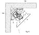
- Fig. 4
- die Schnittdarstellung eines zweiten Ausführungsbeispiels einer erfindungsgemäßen Eckleuchte;
- Fig. 5
- ein drittes Ausführungsbeispiel einer erfindungsgemäßen Leuchte in Schnittdarstellung und
- Fig. 6
- eine Frontalansicht der Leuchte von Fig. 5.
- Fig. 1
- the overall view of a first embodiment of an inventively designed corner lamp;
- Fig. 2a and 2b
- the embodiment of a carrier element according to the invention for mounting the corner lamp;
- Fig. 3a and 3b
- the embodiment of a support member for mounting a decorative cover;
- Fig. 4
- the sectional view of a second embodiment of a corner lamp according to the invention;
- Fig. 5
- a third embodiment of a luminaire according to the invention in a sectional view and
- Fig. 6
- a frontal view of the lamp of FIG. 5th
Fig. 1 zeigt die Seitenansicht einer allgemein mit dem Bezugszeichen 1 versehenen Leuchte, welche im Eckbereich zwischen der Decke 100a und einer Wand 100b eines zu beleuchtenden Raumes angeordnet ist. Die Leuchte 1 soll dazu genutzt werden, die an den Eckbereich angrenzenden Bereiche der Decke 100a und der Wand 100b gleichmäßig auszuleuchten, was mit Hilfe speziell angeordneter Lichtquellen und optischer Elemente erzielt wird, die später noch näher erläutert werden. Angemerkt werden soll zunächst allerdings, dass die erfindungsgemäße Leuchte 1 selbstverständlich auch vertikal in dem Eckbereich zwischen zwei Seitenwänden angeordnet werden kann, um die Bereiche der beiden aneinandergrenzenden Wände auszuleuchten.
Die erfindungsgemäße Leuchte 1 ist im dargestellten Ausführungsbeispiel als Lichtband ausgestaltet, welches im wesentlichen entsprechend dem aus der DE 100 25 647 A1 bekannten Lichtbandsystem ausgeführt ist. Basiselement bzw. Basiskörper der Leuchte 1 ist in diesem Fall eine längliche Tragschiene 20, innerhalb der (nicht dargestellte) Leitungen zur Stromversorgung sowie zur evtl. Übermittlung von Steuerinformationen verlaufen. Auf diese Tragschiene 20 werden einzelne sog. Leuchtenmodule 30 aufgesetzt, welche Fassungen 32 zum Anschließen von länglichen Leuchtstofflampen aufweisen sowie einen Reflektor 25 tragen, der zur Ausleuchtung der an den Eckbereichen angrenzenden Decken- und Wandbereiche ausgestaltet ist. Wie bspw. den Darstellungen in den Fig. 4 und 5 näher entnommen werden kann, besteht der Reflektor 25 aus zwei seitlichen Flügeln 25a und 25b die in Abstrahlrichtung gesehen seitlich hinter den Lichtquellen angeordnet und derart geschwungen sind, dass das von den Lichtquellen auf die Reflektorflügel 25a, 25b fallende Licht in Richtung der zur beleuchtenden Decken- und Wandbereiche abgegeben wird. Wie ferner den Darstellungen in den Fig. 4 und 5 entnommen werden kann, ist dem Reflektor 25 gegenüberliegend noch ein zusätzlicher Kopfreflektor 33 angeordnet, der das von der Lichtquelle abgegebene Licht zurück auf den Hauptreflektor 25 wirft und damit für eine optimale Nutzung des erzeugten Lichts sorgt.Fig. 1 shows a side view of a generally provided with the
The
Die Stromversorgung des Leuchtenmoduls 30 erfolgt mit Hilfe eines als Drehknebel ausgestalteten Stromabgriffs 31, der in die U-förmig gestaltete Tragschiene 20 eingeführt wird, um die verschiedenen Stromversorgungs- und Steuerleitungen zu kontaktieren. Hinsichtlich der speziellen Ausgestaltung dieses Drehknebels kann wiederum auf die zuvor erwähnte DE 100 25 647 A1 verwiesen werden. Insbesondere ist der Drehknebel 31 auch derart ausgestaltet, dass bei einem Verdrehen und entsprechenden Kontaktieren der Leitungen gleichzeitig auch eine mechanische Verrastung zwischen dem Leuchtenmodul 30 und der Tragschiene 20 erfolgt.The power supply of the
Die Befestigung des Reflektors 25 an dem Leuchtenmodul erfolgt vorzugsweise mit Hilfe einer speziell ausgestalteten Befestigungsfeder, die in der DE 101 04 266 A1 beschrieben ist und ein einfaches Aufschnappen des Reflektors 25 auf das Leuchtenmodul 30 ermöglicht. Der Kopfreflektor 33 wiederum kann an den Fassungen 32 mit Hilfe eines Kunststoffklipps befestigt werden. Das an die Tragschiene 20 anzusetzende Leuchtenmodul 30 weist damit zumindest den Stromabgriff 31, die Lampenfassungen 32, den Hauptreflektor 25 sowie den Kopfreflektor 33 auf. Beide Reflektoren 25 und 33 bestehen dabei vorzugsweise aus mattem Aluminium oder einem weiß vorlackierten Blech. Ferner kann das Leuchtenmodul 30 auch ein Betriebsgerät zum Betreiben der als Lichtquellen verwendeten Gasentladungs- bzw. Leuchtstofflampen aufweisen.The attachment of the
Der Hauptreflektor 25 ist wie bereits erwähnt derart ausgestaltet, dass die angrenzenden Raumflächen der Decke 100a sowie der Wand 100b relativ gleichmäßig ausgeleuchtet werden. Dies ist allerdings lediglich dann möglich, wenn der Reflektor 25, also genau genommen die den Basiskörper der Leuchte 1 bildende Tragschiene 20 in geeigneter Weise in dem Eckbereich zwischen der Decke 100a und der Wand 100b angeordnet und ausgerichtet ist. Um diese genaue Anordnung sicherzustellen, ist nunmehr ein erfindungsgemäßes Trägerelement vorgesehen, mittels dem die Tragschiene 20 in dem Eckbereich montiert ist und welches näher in den Fig. 2a und 2b dargestellt ist.The
Das allgemein mit dem Bezugszeichen 5 versehene Trägerelement besteht aus zwei C-förmigen Teilen, einem Grundelement 10 sowie einem Trageteil 15. Das Grundelement 10 weist zwei versteifte Seitenwände 12a und 12b auf, welche zur Befestigung an den jeweiligen Wandbereichen vorgesehen sind, einen rechten Winkel miteinander einschließen und über eine diagonal verlaufende Bodenseite 11 miteinander verbunden sind. Das Grundelement 10 wird also unmittelbar an den Wänden bzw. der Decke und der Wand montiert und sorgt für eine feste Verankerung der Leuchte 1 an den Wänden.The carrier element generally designated by the
Aufgabe des Trageteils 15 ist es, die Tragschiene bzw. allgemein den Basiskörper der Eckleuchte 1 zu halten. Wiederum besteht das Trageteil aus zwei Seitenwänden 17a und 17b, welche über eine Bodenwand 16 miteinander verbunden sind, wobei nun allerdings die beiden Seitenwände 17a und 17b unterschiedliche Aufgaben besitzen. Die erste Seitenwand 17a ist nämlich mit der entsprechenden Seitenwand 12a des Grundelements 10 verbunden, während hingegen die zweite Seitenwand 17b frei zur Innenseite ragt und zur Halterung des Basiskörpers der Leuchte, also im dargestellten Fall der Tragschiene 20 vorgesehen ist.The task of the
Wesentlich ist, dass die erste Seitenwand 17a nicht fest mit der Seitenwand 12a des Grundelements 10 verbunden ist, sondern stattdessen gegenüber dieser Seitenwand 12a verstellbar ist. Hierzu ist ein Schraubenantrieb 13 vorgesehen, der mit beiden Seitenwänden 12a und 17a zusammenwirkt und über eine Schraube 14 an der Stirnseite des Grundelements 10 betätigt werden kann. Entsprechend der Darstellung in Fig. 1 kann somit das Trageteil 15 im Vergleich zu dem Grundelement 10 in Pfeilrichtung, also in einer Richtung, die senkrecht zur Längsachse der Tragschiene 20 verläuft, bewegt werden. Hierdurch wird letztendlich die Möglichkeit geschaffen, eine genaue Justierung der Leuchtenposition in dem Eckbereich vorzunehmen. Dies ist sowohl für den Fall wichtig, dass mehrere getrennte Leuchten nacheinander bzw. übereinander angeordnet werden müssen, als auch für den dargestellten Fall, dass nämliche eine längere Stromschiene 20 in dem Eckbereich montiert werden soll, an der mehrere Leuchtenmodule montiert werden können. In beiden Fällen ist es wichtig, die Leuchten bzw. die Stromschiene 20 exakt fluchtend in der Diagonale zwischen der Decke 100a und der 100b anzuordnen, um eine gleichmäßig Aufhellung beider Raumflächen zu ermöglichen. Das erfindungsgemäß ausgestaltete Trägerelement 5 gestattet dies auf eine sehr einfache und elegante Weise und sorgt trotz allem für eine sichere Halterung der Leuchte an der Decke bzw. Wand. Hierbei ist insbesondere auch zu beachten, dass die Verstellung des Trageteils 15 und damit die Justage der Leuchtenposition auch noch nach Montage der Leuchten erfolgen kann.It is essential that the
Die Halterung der Tragschiene 20 an dem Trageteil 15 des Trägerelements 5 erfolgt vorzugsweise mittels einer Klemmfeder 60, deren Ausgestaltung ebenfalls den Darstellungen in den Fig. 2a und 2b entnommen werden kann. Die Feder 60, die bspw. mittels zweier Schrauben an der Seitenwand 17b des Trageteils 15 befestigt ist, weist obere und untere Rastvorsprünge 61 und 62 auf, welche mit entsprechenden Profilnuten der Tragschiene 20 zusammenwirken und für eine sichere Verrastung zwischen der Tragschiene und dem Trägerteil 5 sorgen. Gleichzeitig sind die Federn 60 derart ausgestaltet, dass die Tragschiene in einfacher Weise und werkzeuglos montiert und demontiert kann.The support of the
Eine letzte Komponente der erfindungsgemäßen Eckleuchte 1, die bislang noch nicht besprochen wurde, ist eine Dekorabdeckung 50, welche dazu vorgesehen ist, einen direkten Blick auf die verschiedenen Elemente der Leuchte 1 zu verhindern. Die in Fig. 1 dargestellte Dekorabdeckung 50 besteht aus einem bogenförmig geschwungenen, lichtundurchlässigen Element, welches an der Eckleuchte 1 befestigt wird und in Lichtabstrahlrichtung gesehen unterhalb der Lampenfassungen 32 angeordnet ist. Die seitliche Lichtabgabe zum Aufhellen der Wandbereiche wird durch die Dekorabdeckung 50 selbstverständlich nicht beeinträchtigt. Zwar wird durch die Dekorabdeckung 50 unmittelbar im Eckbereich zwischen beiden Wänden bzw. der Decke 100a und der Wand 100b ein dunkler Streifen erzeugt, von dem seitlich Licht ausgeht, dies wird allerdings in Kauf genommen, da andernfalls Blendeffekte auftreten könnten. Selbstverständlich wäre es allerdings auch denkbar, zumindest teilweise Licht über die Dekorabdeckung 50 durch entsprechende Öffnungen abzugeben.A final component of the
Wesentlich ist wiederum, dass auch die Dekorabdeckung 50 in sehr einfacher Weise an der Leuchte 1, insbesondere an der Tragschiene 20 befestigt werden kann. Dies erfolgt mit Hilfe eines besonderen Halterungselements 40, dessen Ausgestaltung näher den Fig. 3a und 3b entnommen werden kann. Das als Haltebügel ausgestaltete Halterungselement 40 besteht zum einen aus einem Flügelteil 42 sowie zum anderen aus einem Befestigungsteil 41, welches mittels einer Schraube an dem Flügelteil 42 befestigt ist und wiederum zur Halterung einer Klemmfeder 60 vorgesehen ist, die identisch zu der bereits im Zusammenhang mit der Halterung der Tragschiene 20 an dem Trägerelement 5 besprochenen Klemmfeder 60 ausgestaltet ist. Wie der Darstellung in Fig. 1 entnommen werden kann, wird nämlich mit Hilfe der Klemmfeder 60 das Halterungselement 40 an der anderen Seite der Tragschiene 20 verrastet, wobei die Vorsprünge 61 und 62 der Klemmfeder 60 wieder in die entsprechenden in Längsrichtung verlaufenden Nuten der Profilierung der Tragschiene 20 eingreifen.It is essential again that the
Das Flügelteil 42 des Halterungselements 40 weist nun zwei seitliche Arme 44 und 45 auf, die in ihren Endbereich jeweils eine Ausnehmung bzw. einen Schlitz 44a und 45a aufweisen. Wie der Darstellung in Fig. 1 entnommen werden kann, können in diese Ausnehmungen 44a und 45a in Längsrichtung verlaufende Vorsprünge Dekorabdeckung 50 eingreifen, wodurch eine einfache Verrastung zwischen beiden Elementen erzielt wird. Wesentlich an dieser Ausgestaltung ist, dass hiermit eine freie Anordnung der Dekorabdeckung 50 über die gesamte Länge der Tragschiene 20 hinweg ermöglicht wird.The
Insgesamt gesehen gestaltet sich damit eine Montage der erfindungsgemäßen Eckleuchte 1 wie folgt. Nach der Montage der Trägerelemente 5 in dem Eckbereich kann die Tragschiene 20 mit Hilfe der Klemmfedern 60 an den Trägerelementen 5 aufgeklemmt werden. Anschließend werden auf die Tragschiene 20 die verschiedenen Leuchtenmodule 30 aufgesetzt, wobei in einem weiteren Schritt dann mehrere Halterungselemente 40 an der Tragschiene 20 verrastet werden. Anschließend wird der Hauptreflektor 25 mittels der speziellen Klemmfeder an den Leuchtenmodulen befestigt. Entsprechend der Länge des Reflektors werden nunmehr die Halterungselemente 40 für die Dekorabdeckung 50 in Längsrichtung positioniert. Nachdem die Leuchtmittel, also bspw. die Leuchtstofflampen in die Fassungen eingesetzt und der Kopfreflektor 33 angesetzt wurden, wird schließlich in einem abschließenden Montageschritt die Dekorabdeckung 50 an den Halterungselementen 40 eingehängt. Festzustellen ist also, dass abgesehen von der Montage der Trägerelemente 5 die gesamte Montage der Eckleuchte 1 werkzeuglos und dementsprechend sehr einfach und schnell erfolgt.Overall, thus designed for mounting the
Abschließend ist noch darauf hinzuweisen, dass durch die spezielle Ausgestaltung der Halterungselemente 40 auch die Möglichkeit besteht, unterschiedlich gestaltete Dekorabdeckungen zu montieren. Weitere Beispiele sind in den Fig. 4 und 5 dargestellt, wobei ferner Fig. 6 die Frontalansicht der erfindungsgemäßen Leuchte mit der in Fig. 5 dargestellten Dekorabdeckung 53 zeigt. Wie der Darstellung in Fig. 6 ferner entnommen werden kann, kann die Dekorabdeckung 53 zusätzliche Öffnungen 53a aufweisen, welche bspw. zu einer ergänzenden Lichtabgabe eingesetzt werden könnten oder in denen die Montage zusätzlicher Lichtspots oder Lautsprecher ermöglicht wird. Hierbei ist anzumerken, dass in solchen Fällen, in denen die Abdeckung höheren Belastungen ausgesetzt ist, auch noch eine ergänzende Fixierung der Dekorabdeckungen durch zusätzliche Befestigungs- oder Sicherungselemente denkbar wäre. Dies wäre insbesondere dann sinnvoll, wenn die Dekorabdeckung Zusatzfunktionen ausüben soll, welche einem Innenausbauer eine größtmögliche Freiheit bei der Gestaltung ermöglichen. So kann die Dekorabdeckung auch für die Aufnahme von Gipsstukaturen, Wandteppichen, Furnieren, Tapeten etc. vorgesehen sein. Eine Ausgestaltung als Aluminium-Strangpreßprofil gewährleistet in diesem Fall über eine größere Länge hinweg die erforderliche Gleichmäßigkeit und ausreichende Stabilität.Finally, it should be pointed out that the special design of the
Insgesamt wird somit ein Konzept für eine Eckleuchte vorgestellt, die einerseits in sehr einfacher und überwiegend werkzeugloser Weise montiert werden kann. Gleichzeitig ist allerdings die Montage der Leuchte derart ausgestaltet, dass eine exakte Anordnung und Ausrichtung der Leuchte in dem Eckbereich ermöglicht wird, so dass eine gleichmäßige Lichtabstrahlung zu den beiden Seiten hin erzielt werden kann.Overall, a concept for a corner light is presented, which can be mounted on the one hand in a very simple and mostly tool-free manner. At the same time, however, the mounting of the lamp is designed such that an exact arrangement and orientation of the lamp is made possible in the corner, so that a uniform light emission to the two sides can be achieved.
Claims (24)
wobei die Leuchte (1) einen Basiskörper (20) aufweist, der mittels mindestens einem Trägerelement (5) an den Wänden (100a, 100b) bzw. der Wand und der Decke zu befestigen ist, wobei an dem Basiskörper (20) oder weiteren Anbauelementen Anschlußmittel (32) für mindestens eine Lichtquelle sowie einen Reflektor (25) zur Ausleuchtung der an den Eckbereich angrenzenden Decken- bzw. Wandbereiche angeordnet sind,
dadurch gekennzeichnet,
dass das Trägerelement (5) aus einem an den Wänden (100a, 100b) bzw. der Wand und der Decke zu befestigenden Grundelement (10) sowie einem an dem Grundelement (10) befestigten und den Basiskörper (20) haltenden Trageteil (15) besteht, wobei das Trageteil (15) gegenüber dem Grundelement (10) verstellbar ist.Luminaire (1), which is intended to be mounted in the corner between two adjoining walls (100a, 100b) or between a wall and a ceiling,
wherein the luminaire (1) has a base body (20) which is to be fastened to the walls (100a, 100b) or the wall and the ceiling by means of at least one carrier element (5), wherein on the base body (20) or further attachment elements Connecting means (32) are arranged for at least one light source and a reflector (25) for illuminating the ceiling or wall areas adjoining the corner area,
characterized,
in that the carrier element (5) consists of a base element (10) to be fastened to the walls (100a, 100b) or the wall and the ceiling and to a support element (15) fastened to the base element (10) and holding the base body (20) , wherein the support member (15) relative to the base member (10) is adjustable.
dadurch gekennzeichnet,
dass das Grundelement (10) C-förmig gestaltet ist und zwei Seitenschenkel (12a, 12b) aufweist, welche zur Befestigung an jeweils einer der beiden Wände (100a, 100b) bzw. der Wand und der Decke vorgesehen sind.Luminaire according to claim 1,
characterized,
in that the base element (10) is C-shaped and has two side legs (12a, 12b) which are provided for attachment to one of the two walls (100a, 100b) or the wall and the ceiling.
dadurch gekennzeichnet,
dass das Trageteil (15) an einem der beiden Seitenschenkel (12a, 12b) befestigt und entlang diesem Schenkel (12a, 12b) in einer Richtung senkrecht zu einer Längsachse der Leuchte (1) verstellbar ist.Luminaire according to claim 2,
characterized,
in that the carrying part (15) is fastened to one of the two side limbs (12a, 12b) and is adjustable along this limb (12a, 12b) in a direction perpendicular to a longitudinal axis of the luminaire (1).
dadurch gekennzeichnet,
dass das Trageteil (15) ebenfalls C-förmig ausgestaltet ist, wobei ein erster Seitenschenkel (17a) des Trageteils (15) an dem Grundelement (10) befestigt ist und ein zweiter Seitenschenkel (17b) des Trageteils (15) den Basiskörper (20) trägt.Luminaire according to claim 2 or 3,
characterized,
in that the support part (15) is likewise C-shaped, a first side limb (17a) of the support part (15) being fastened to the base element (10) and a second side limb (17b) of the support part (15) securing the base body (20). wearing.
dadurch gekennzeichnet,
dass das Trägerelement (5) einen Schraubenantrieb (13) zum Verstellen des Trageteils (15) gegenüber dem Grundelement (10) aufweist.Luminaire according to claim 4,
characterized,
that the carrier element (5) has a screw drive (13) for adjusting the carrying part (15) relative to the base member (10).
dadurch gekennzeichnet,
dass der Basiskörper (20) mit dem Trageteil (15) des Trägerelements (5) verrastbar ist.Luminaire according to one of the preceding claims,
characterized,
in that the base body (20) can be latched to the carrier part (15) of the carrier element (5).
dadurch gekennzeichnet,
dass an dem Trageteil (15) eine Klemmfeder (60) angeordnet ist, welche mit dem Basiskörper (20) zusammenwirkende Rastvorsprünge (61, 62) aufweist.Luminaire according to claim 6,
characterized,
in that a clamping spring (60), which has latching projections (61, 62) cooperating with the base body (20), is arranged on the carrying part (15).
dadurch gekennzeichnet,
dass der Basiskörper durch eine Tragschiene (20) eines Stromschienensystems gebildet ist, an der ein Leuchtenmodul (30) befestigt ist, welches die Anschlußmittel (32) für die Lichtquelle sowie den Reflektor (25) aufweist.Luminaire according to one of the preceding claims,
characterized,
in that the base body is formed by a support rail (20) of a busbar system, to which a luminaire module (30) is fastened, which has the connection means (32) for the light source and the reflector (25).
dadurch gekennzeichnet,
dass das Profil der Tragschiene (20) in Längsrichtung verlaufende Nuten aufweist, in welche die Rastvorsprünge (61, 62) der Klemmfeder (60) eingreifen.Luminaire according to claim 7 and claim 8,
characterized,
in that the profile of the mounting rail (20) has grooves extending in the longitudinal direction into which the latching projections (61, 62) of the clamping spring (60) engage.
dadurch gekennzeichnet,
dass das Leuchtenmodul (30) einen Stromabgriff (31) zum Kontaktieren von in der Tragschiene (20) verlaufenden Stromversorgungsleitungen und/oder Steuerleitungen zum Übermitteln von Steuersignalen für die Leuchte (1) aufweist.Luminaire according to claim 8 or 9,
characterized,
in that the luminaire module (30) has a current pick-up (31) for contacting power supply lines running in the mounting rail (20) and / or control lines for transmitting control signals for the luminaire (1).
dadurch gekennzeichnet,
dass der Reflektor (25) mit dem Leuchtenmodul (30) verrastet ist.Luminaire according to one of claims 8 to 10,
characterized,
that the reflector is locked (25) to the lamp module (30).
dadurch gekennzeichnet,
dass der Reflektor (25) zwei seitliche Reflektorflügel (25a, 25b) zur Ausleuchtung jeweils einer Wand (100a, 100b) bzw. der Wand und der Decke aufweist.Luminaire according to one of the preceding claims,
characterized,
that the reflector (25) has two lateral reflector wings (25a, 25b) for illuminating each of a wall (100a, 100b) or the wall and the ceiling.
dadurch gekennzeichnet,
dass diese einen dem Reflektor (25) gegenüberliegenden Kopfreflektor (33) aufweist.Luminaire according to one of the preceding claims,
characterized,
in that it has a head reflector (33) opposite the reflector (25).
dadurch gekennzeichnet,
dass diese eine an dem Basisteil (20) der Leuchte (1) befestigte Dekorabdeckung (50, 52, 53) aufweist.Luminaire according to one of the preceding claims,
characterized,
in that it has a decorative cover (50, 52, 53) attached to the base part (20) of the luminaire (1).
dadurch gekennzeichnet,
dass die Dekorabdeckung (50, 52, 53) mit einem an dem Basisteil (20) befestigten Halterungselement (40) verrastet ist.Luminaire according to claim 14,
characterized,
in that the decorative cover (50, 52, 53) is latched with a retaining element (40) fastened to the base part (20).
dadurch gekennzeichnet,
dass die Dekorabdeckung (50, 52, 53) zwei seitliche und in Längsrichtung verlaufende Rastvorsprünge (51) aufweist, welche in entsprechende Ausnehmungen (44a, 45a) des Halterungselements (40) eingreifen.Luminaire according to claim 15,
characterized,
in that the decorative cover (50, 52, 53) has two lateral and longitudinal latching projections (51) which engage in corresponding recesses (44a, 45a) of the mounting element (40).
dadurch gekennzeichnet,
dass das Trägerelement (5) aus einem an den Wänden (100a, 100b) bzw. der Wand und der Decke zu befestigenden Grundelement (10) sowie einem an dem Grundelement (10) befestigten und einen Basiskörper (20) einer Leuchte (1) haltenden Trageteil (15) besteht, wobei das Trageteil (15) gegenüber dem Grundelement (10) verstellbar ist.Carrier element (5) for mounting a luminaire (1) in the corner region between two adjoining walls (100a, 100b) or between a wall and a ceiling,
characterized,
in that the carrier element (5) consists of a base element (10) to be fastened to the walls (100a, 100b) or the wall and the ceiling and to a base element (10) and a base body (20) of a luminaire (1) Support member (15), wherein the support member (15) relative to the base member (10) is adjustable.
dadurch gekennzeichnet,
dass das Grundelement (10) C-förmig gestaltet ist und zwei Seitenschenkel (12a, 12b) aufweist, welche zur Befestigung an jeweils einer der beiden Wände (100a, 100b) bzw. der Wand und der Decke vorgesehen sind.Carrier element according to claim 17,
characterized,
in that the base element (10) is C-shaped and has two side legs (12a, 12b) which are provided for attachment to one of the two walls (100a, 100b) or the wall and the ceiling.
dadurch gekennzeichnet,
dass das Trageteil (15) an einem der beiden Seitenschenkel (12a, 12b) befestigt und entlang diesem Schenkel (12a, 12b) in einer Richtung senkrecht zu einer Längsachse der Leuchte (1) verstellbar ist.Carrier element according to claim 18,
characterized,
in that the carrying part (15) is fastened to one of the two side limbs (12a, 12b) and is adjustable along this limb (12a, 12b) in a direction perpendicular to a longitudinal axis of the luminaire (1).
dadurch gekennzeichnet,
dass das Trageteil (15) ebenfalls C-förmig ausgestaltet ist, wobei ein erster Seitenschenkel (17a) des Trageteils (15) an dem Grundelement (10) befestigt ist und ein zweiter Seitenschenkel (17b) des Trageteils (15) den Basiskörper (20) trägt.Carrier element according to claim 18 or 19,
characterized,
in that the support part (15) is likewise C-shaped, a first side limb (17a) of the support part (15) being fastened to the base element (10) and a second side limb (17b) of the support part (15) securing the base body (20). wearing.
dadurch gekennzeichnet,
dass das Trägerelement (5) einen Schraubenantrieb (13) zum Verstellen des Trageteils (15) gegenüber dem Grundelement (10) aufweist.Carrier element according to claim 20,
characterized,
that the carrier element (5) has a screw drive (13) for adjusting the carrying part (15) relative to the base member (10).
wobei die Leuchte (1) einen an den Wänden (100a, 100b) bzw. der Wand und der Decke zu befestigenden Basiskörper (20) aufweist, der Anschlußmittel (32) für eine Lichtquelle sowie einen Reflektor (25) zur Ausleuchtung der an den Eckbereich angrenzenden Decken- bzw. Wandbereiche aufweist,
und wobei ferner eine Dekorabdeckung (50, 52, 53) vorgesehen ist,
dadurch gekennzeichnet,
dass die Dekorabdeckung (50, 52, 53) mit dem Basiskörper (20) verrastet ist.Luminaire (1), which is intended to be mounted in the corner between two adjoining walls (100a, 100b) or between a wall and a ceiling,
wherein the luminaire (1) has a base body (20) to be fixed to the walls (100a, 100b) or the wall and the ceiling, the connection means (32) for a light source and a reflector (25) for illuminating the corner area has adjoining ceiling or wall areas,
and further comprising a decorative cover (50, 52, 53),
characterized,
that the decorative covering (50, 52, 53) is latched to the base body (20).
dadurch gekennzeichnet,
dass die Dekorabdeckung (50, 52, 53) mit einem an dem Basisteil (20) befestigten Halterungselement (40) verrastet ist.Luminaire according to claim 22,
characterized,
in that the decorative cover (50, 52, 53) is latched with a retaining element (40) fastened to the base part (20).
dadurch gekennzeichnet,
dass die Dekorabdeckung (50, 52, 53) zwei seitliche und in Längsrichtung verlaufende Rastvorsprünge (51) aufweist, welche in entsprechende Ausnehmungen (44a, 45a) des Halterungselements (40) eingreifen.Luminaire according to claim 23,
characterized,
in that the decorative cover (50, 52, 53) has two lateral and longitudinal latching projections (51) which engage in corresponding recesses (44a, 45a) of the mounting element (40).
Applications Claiming Priority (1)
| Application Number | Priority Date | Filing Date | Title |
|---|---|---|---|
| DE102004051826A DE102004051826A1 (en) | 2004-10-25 | 2004-10-25 | corner light |
Publications (3)
| Publication Number | Publication Date |
|---|---|
| EP1650495A2 true EP1650495A2 (en) | 2006-04-26 |
| EP1650495A3 EP1650495A3 (en) | 2006-05-24 |
| EP1650495B1 EP1650495B1 (en) | 2008-01-23 |
Family
ID=35589616
Family Applications (1)
| Application Number | Title | Priority Date | Filing Date |
|---|---|---|---|
| EP05023032A Not-in-force EP1650495B1 (en) | 2004-10-25 | 2005-10-21 | Corner lamp |
Country Status (3)
| Country | Link |
|---|---|
| EP (1) | EP1650495B1 (en) |
| AT (1) | ATE384914T1 (en) |
| DE (2) | DE102004051826A1 (en) |
Cited By (3)
| Publication number | Priority date | Publication date | Assignee | Title |
|---|---|---|---|---|
| DE102009004351A1 (en) | 2009-01-08 | 2011-02-17 | Briloner Industrie Service GbR (vertretungsberechtigter Gesellschafter: Josef Hillebrand, 34431 Marsberg) | Lamp has supporting element has two holding devices which is contributed for holding lamp covering, where adhesive acting connecting device is carried out as magnetic device |
| CN103162206A (en) * | 2011-12-15 | 2013-06-19 | 海洋王照明科技股份有限公司 | Light emitting diode (LED) corner lamp for warships |
| DE102012007284A1 (en) * | 2012-04-13 | 2013-10-17 | Ueberholz Gmbh | Power supply device with a base body to which adapters can be fastened at various locations, wherein at least one electrical load of at least two adapters can be fastened to the base body |
Citations (2)
| Publication number | Priority date | Publication date | Assignee | Title |
|---|---|---|---|---|
| DE10025647A1 (en) | 2000-05-24 | 2001-11-29 | Zumtobel Staff Gmbh | Current rail system for lamps has bearer rail containing current conducting profile consisting of at least two wire holding elements joined together with grooves for accommodating wires |
| DE10104266A1 (en) | 2001-01-31 | 2002-08-01 | Zumtobel Staff Gmbh | Luminaire with fastening element |
Family Cites Families (10)
| Publication number | Priority date | Publication date | Assignee | Title |
|---|---|---|---|---|
| US3210875A (en) * | 1963-02-05 | 1965-10-12 | Patent License Corp | Lighting fixture |
| US4352151A (en) * | 1978-04-28 | 1982-09-28 | Lewis Andrew G | Lighting apparatus |
| US4338653A (en) * | 1980-09-24 | 1982-07-06 | Louis Marrero | Versatile fluorescent lighting fixture |
| US4862333A (en) * | 1988-07-29 | 1989-08-29 | Brasket Denis R | Corner wall lamp |
| DE4024826C2 (en) * | 1990-08-04 | 1993-10-07 | Halloform Gmbh & Co Kg | Track system |
| US5297011A (en) * | 1992-08-12 | 1994-03-22 | George Triunfol | Lighted corner guard |
| DE4233481A1 (en) * | 1992-10-05 | 1994-04-07 | Hubert Kurz | Light fitting for wooden bathing cubicle for several types of bath e.g. sauna - has at least one electric lamp with horizontal and vertical movable shades covering lamp and includes frame fixed at cubicle wall or cubicle ceiling |
| DE20007591U1 (en) * | 2000-04-27 | 2001-09-06 | Hymer Ag | Luminaire for a land, water or aircraft, especially a motorhome |
| DE20215834U1 (en) * | 2002-10-15 | 2004-02-26 | Tridonicatco Gmbh & Co. Kg | Low voltage lighting using light emitting diodes that are mounted in a line within a profiled extruded material strip |
| DE10307147A1 (en) * | 2003-02-20 | 2004-09-23 | Airbus Deutschland Gmbh | Reading light for aircraft cabins |
-
2004
- 2004-10-25 DE DE102004051826A patent/DE102004051826A1/en not_active Withdrawn
-
2005
- 2005-10-21 AT AT05023032T patent/ATE384914T1/en not_active IP Right Cessation
- 2005-10-21 EP EP05023032A patent/EP1650495B1/en not_active Not-in-force
- 2005-10-21 DE DE502005002637T patent/DE502005002637D1/en active Active
Patent Citations (2)
| Publication number | Priority date | Publication date | Assignee | Title |
|---|---|---|---|---|
| DE10025647A1 (en) | 2000-05-24 | 2001-11-29 | Zumtobel Staff Gmbh | Current rail system for lamps has bearer rail containing current conducting profile consisting of at least two wire holding elements joined together with grooves for accommodating wires |
| DE10104266A1 (en) | 2001-01-31 | 2002-08-01 | Zumtobel Staff Gmbh | Luminaire with fastening element |
Cited By (4)
| Publication number | Priority date | Publication date | Assignee | Title |
|---|---|---|---|---|
| DE102009004351A1 (en) | 2009-01-08 | 2011-02-17 | Briloner Industrie Service GbR (vertretungsberechtigter Gesellschafter: Josef Hillebrand, 34431 Marsberg) | Lamp has supporting element has two holding devices which is contributed for holding lamp covering, where adhesive acting connecting device is carried out as magnetic device |
| DE102009004351B4 (en) * | 2009-01-08 | 2011-05-05 | Briloner Industrie Service GbR (vertretungsberechtigter Gesellschafter: Josef Hillebrand, 34431 Marsberg) | Luminaire with flexible support element |
| CN103162206A (en) * | 2011-12-15 | 2013-06-19 | 海洋王照明科技股份有限公司 | Light emitting diode (LED) corner lamp for warships |
| DE102012007284A1 (en) * | 2012-04-13 | 2013-10-17 | Ueberholz Gmbh | Power supply device with a base body to which adapters can be fastened at various locations, wherein at least one electrical load of at least two adapters can be fastened to the base body |
Also Published As
| Publication number | Publication date |
|---|---|
| DE102004051826A1 (en) | 2006-05-04 |
| EP1650495B1 (en) | 2008-01-23 |
| DE502005002637D1 (en) | 2008-03-13 |
| ATE384914T1 (en) | 2008-02-15 |
| EP1650495A3 (en) | 2006-05-24 |
Similar Documents
| Publication | Publication Date | Title |
|---|---|---|
| EP2151899B1 (en) | Light strip system | |
| EP0898686B2 (en) | Lighting fitting with a basic unit as support for at least one lamp | |
| EP2375128A2 (en) | Light fixture with LEDs and lenses assigned to the LEDs | |
| EP2880362B1 (en) | Fastening system for fastening at least one lighting unit in an elongated, curved installation opening | |
| AT513339B1 (en) | Light module for a motor vehicle and motor vehicle headlights | |
| EP3320259B1 (en) | Lamp for forming a light line | |
| EP1650495B1 (en) | Corner lamp | |
| EP2507543B2 (en) | Wall and/or ceiling system for illumination | |
| EP3270047A2 (en) | Flat light | |
| EP3063040A1 (en) | Lighting device and headlight for a motor vehicle | |
| EP2641508B1 (en) | Lighting device for shelves | |
| DE102016203810A1 (en) | Luminaire for uniform illumination | |
| EP2175188B1 (en) | Lamp | |
| DE4202768C2 (en) | lamp | |
| DE202016104062U1 (en) | Arrangement for emitting light | |
| EP1538394B1 (en) | Profile frame light | |
| EP3869091B1 (en) | Fastening device for lighting means | |
| EP1538391B1 (en) | Luminaire with profile element for fixing to a pendant | |
| DE19833217B4 (en) | module light | |
| EP2672171B1 (en) | Light, in particular for a light ribbon | |
| DE202012100628U1 (en) | Luminaire with an elongated housing and attachment element for this purpose | |
| EP1540245B1 (en) | Luminaire comprising a cover/reflector module | |
| DE10029405B4 (en) | Luminaire for attachment to a carrier | |
| EP2085684A1 (en) | Lamp with self-supporting reflector unit | |
| EP2994690B1 (en) | Light fixture with a housing having a plurality of light-emitting openings |
Legal Events
| Date | Code | Title | Description |
|---|---|---|---|
| PUAI | Public reference made under article 153(3) epc to a published international application that has entered the european phase |
Free format text: ORIGINAL CODE: 0009012 |
|
| PUAL | Search report despatched |
Free format text: ORIGINAL CODE: 0009013 |
|
| AK | Designated contracting states |
Kind code of ref document: A2 Designated state(s): AT BE BG CH CY CZ DE DK EE ES FI FR GB GR HU IE IS IT LI LT LU LV MC NL PL PT RO SE SI SK TR |
|
| AX | Request for extension of the european patent |
Extension state: AL BA HR MK YU |
|
| AK | Designated contracting states |
Kind code of ref document: A3 Designated state(s): AT BE BG CH CY CZ DE DK EE ES FI FR GB GR HU IE IS IT LI LT LU LV MC NL PL PT RO SE SI SK TR |
|
| AX | Request for extension of the european patent |
Extension state: AL BA HR MK YU |
|
| 17P | Request for examination filed |
Effective date: 20061106 |
|
| 17Q | First examination report despatched |
Effective date: 20061214 |
|
| AKX | Designation fees paid |
Designated state(s): AT CH DE IT LI |
|
| RAP1 | Party data changed (applicant data changed or rights of an application transferred) |
Owner name: ZUMTOBEL LIGHTING GMBH |
|
| GRAP | Despatch of communication of intention to grant a patent |
Free format text: ORIGINAL CODE: EPIDOSNIGR1 |
|
| GRAS | Grant fee paid |
Free format text: ORIGINAL CODE: EPIDOSNIGR3 |
|
| GRAA | (expected) grant |
Free format text: ORIGINAL CODE: 0009210 |
|
| AK | Designated contracting states |
Kind code of ref document: B1 Designated state(s): AT CH DE IT LI |
|
| REG | Reference to a national code |
Ref country code: CH Ref legal event code: EP |
|
| REF | Corresponds to: |
Ref document number: 502005002637 Country of ref document: DE Date of ref document: 20080313 Kind code of ref document: P |
|
| PLBE | No opposition filed within time limit |
Free format text: ORIGINAL CODE: 0009261 |
|
| STAA | Information on the status of an ep patent application or granted ep patent |
Free format text: STATUS: NO OPPOSITION FILED WITHIN TIME LIMIT |
|
| 26N | No opposition filed |
Effective date: 20081024 |
|
| PG25 | Lapsed in a contracting state [announced via postgrant information from national office to epo] |
Ref country code: IT Free format text: LAPSE BECAUSE OF FAILURE TO SUBMIT A TRANSLATION OF THE DESCRIPTION OR TO PAY THE FEE WITHIN THE PRESCRIBED TIME-LIMIT Effective date: 20080123 |
|
| PG25 | Lapsed in a contracting state [announced via postgrant information from national office to epo] |
Ref country code: AT Free format text: LAPSE BECAUSE OF NON-PAYMENT OF DUE FEES Effective date: 20081021 |
|
| REG | Reference to a national code |
Ref country code: CH Ref legal event code: PL |
|
| PG25 | Lapsed in a contracting state [announced via postgrant information from national office to epo] |
Ref country code: CH Free format text: LAPSE BECAUSE OF NON-PAYMENT OF DUE FEES Effective date: 20091031 Ref country code: LI Free format text: LAPSE BECAUSE OF NON-PAYMENT OF DUE FEES Effective date: 20091031 |
|
| PGFP | Annual fee paid to national office [announced via postgrant information from national office to epo] |
Ref country code: DE Payment date: 20170102 Year of fee payment: 12 |
|
| REG | Reference to a national code |
Ref country code: DE Ref legal event code: R119 Ref document number: 502005002637 Country of ref document: DE |
|
| PG25 | Lapsed in a contracting state [announced via postgrant information from national office to epo] |
Ref country code: DE Free format text: LAPSE BECAUSE OF NON-PAYMENT OF DUE FEES Effective date: 20180501 |