EP1641189B1 - Error ratio measurement in the radio link control layer for quality of service control in a wireless communication system - Google Patents
Error ratio measurement in the radio link control layer for quality of service control in a wireless communication system Download PDFInfo
- Publication number
- EP1641189B1 EP1641189B1 EP04022968A EP04022968A EP1641189B1 EP 1641189 B1 EP1641189 B1 EP 1641189B1 EP 04022968 A EP04022968 A EP 04022968A EP 04022968 A EP04022968 A EP 04022968A EP 1641189 B1 EP1641189 B1 EP 1641189B1
- Authority
- EP
- European Patent Office
- Prior art keywords
- service data
- data units
- error rate
- mobile terminal
- service
- Prior art date
- Legal status (The legal status is an assumption and is not a legal conclusion. Google has not performed a legal analysis and makes no representation as to the accuracy of the status listed.)
- Not-in-force
Links
Images


Classifications
-
- H—ELECTRICITY
- H04—ELECTRIC COMMUNICATION TECHNIQUE
- H04W—WIRELESS COMMUNICATION NETWORKS
- H04W24/00—Supervisory, monitoring or testing arrangements
-
- H—ELECTRICITY
- H04—ELECTRIC COMMUNICATION TECHNIQUE
- H04L—TRANSMISSION OF DIGITAL INFORMATION, e.g. TELEGRAPHIC COMMUNICATION
- H04L12/00—Data switching networks
- H04L12/02—Details
- H04L12/16—Arrangements for providing special services to substations
- H04L12/18—Arrangements for providing special services to substations for broadcast or conference, e.g. multicast
- H04L12/1863—Arrangements for providing special services to substations for broadcast or conference, e.g. multicast comprising mechanisms for improved reliability, e.g. status reports
- H04L12/1868—Measures taken after transmission, e.g. acknowledgments
-
- H—ELECTRICITY
- H04—ELECTRIC COMMUNICATION TECHNIQUE
- H04L—TRANSMISSION OF DIGITAL INFORMATION, e.g. TELEGRAPHIC COMMUNICATION
- H04L12/00—Data switching networks
- H04L12/02—Details
- H04L12/16—Arrangements for providing special services to substations
- H04L12/18—Arrangements for providing special services to substations for broadcast or conference, e.g. multicast
- H04L12/189—Arrangements for providing special services to substations for broadcast or conference, e.g. multicast in combination with wireless systems
-
- H—ELECTRICITY
- H04—ELECTRIC COMMUNICATION TECHNIQUE
- H04W—WIRELESS COMMUNICATION NETWORKS
- H04W84/00—Network topologies
- H04W84/02—Hierarchically pre-organised networks, e.g. paging networks, cellular networks, WLAN [Wireless Local Area Network] or WLL [Wireless Local Loop]
- H04W84/04—Large scale networks; Deep hierarchical networks
Abstract
Description
- This invention generally relates to wireless communication, and in particular to a QoS (quality of service) control mechanism in case of a wireless communication system. It applies in particular to MBMS (Multimedia Broadcast Multicast Service), which is a new UMTS feature currently standardised for the UMTS release 6 within 3GPP. However, the invention is not limited to UMTS but could be applied to any communication system including future mobile communication standards (4G).
- In every communication system, the control of the quality of service (QoS) has always been a widely discussed topic. This is particularly true for wireless communication systems, where the interface between transmitter and receiver generally causes a more or less severe deformation of the physical signal leading to degradation of the received signal quality. In order to cope with this, several methods have been developed. Firstly, some modulation techniques have been specially developed in order to match the physical characteristic of the transmission medium. Secondly, encoding methods are used in order to protect the message from interference. Finally, QoS control mechanisms enable an active control of the reception quality of the transmitted signal. The main idea of this type of techniques is that the receiver informs, by some means, the transmitter about the reception quality in order to allow the transmitter to adapt the transmission characteristics (e.g. transmission power) and meet some predefined QoS attribute targets.
- This invention belongs to the last category and provides a new mechanism for controlling the reception quality of a transmitted signal over a non-error free medium.
- The nature of the information to be transmitted has a strong influence on the way this information should be transmitted. For instance, a voice call has completely different characteristics than a browsing session (internet). In 3GPP TS 23.107v6.1.0 "Quality of Service (QoS) concept and architecture" and in "WCDMA for UMTS, radio access for third generation mobile communications, second edition", Harri Holma and Antti Toskala, Wiley editions, the different types of information expected to be commonly transmitted over 3G are presented. 4 different classes of services have been identified and the following table lists their respective characteristics and envisaged applications.
Table 1: UMTS QoS classes Traffic class Conversational class conversational real time Streaming class streaming real time Interactive class Interactive best effort Background Background best effort Fundamental characteristics - Preserve time relation (variation) between information entities of the stream Conversational pattern (stringent and low delay) -Preserve time relation (variation) between information entities of the stream -Request response pattern -Preserve payload content -Destination is not expecting the data within a certain time -Preserve payload content Example of the - application voice -streaming video -Web browsing -background download of emails - For each of these QoS classes or bearer traffic classes, a list of QoS attributes has been defined and is shown in the following table. If the QoS attributes are met, it is ensured that the message is perceived by the end user with the required quality. The QoS attributes are negotiated between the different elements of the communication chain (UE, RNC, CN elements) during the setup of a connection and depend on the type of service requested and the capabilities of the different nodes. If one of the QoS attributes is not met, the end user will certainly notice a degradation of the communication (e.g. voice distortion, connection interruption, etc).
Table 2: QoS attributes defined for each bearer traffic class Traffic class Conversational class Streaming class Interactive class Background class Maximum bitrate X X X X Delivery order X X X X Maximum SDU size X X X X SDU format information X X SDU error ratio X X X X Residual bit error ratio X X X X Delivery of erroneous SDUs X X X X Transfer delay X X Guaranteed bit rate X X Traffic handling priority X Allocation/ Retention priority X X X X Source statistics descriptor X X Signalling Indication X - A definition of each of these QoS attributes can be found in 3GPP TS 23.107v6.1.0 and Holma and Toskala, both cited above. One of the most important Qos attributes is the "SDU error rate" which refers to the RLC SDU error rate that will be explained in the next section.
- UMTS air interface layers
- In order to enable data transmission over a wireless interface, 3GPP defined a set of layers and their respective protocols, which have the goal to provide the necessary services to support the pre-defined QoS (data rate, error rate, priority etc) defined at the bearer setup.
- As shown in
Fig. 1 , the radio interface is layered into three protocol layers: - the physical layer (L1) 101;
- the data link layer (L2) 102;
- RRC layer (L3) 103.
- Layer 2 is split into the following sub-layers: Medium Access Control (MAC) 104, Radio Link Control (RLC) 105, Packet Data Convergence Protocol (PDCP) 106 and Broadcast/Multicast Control (BMC) 107. Each layer has well defined functions, which are summarized in 3GPP TS 25.301v6.0.0 "Radio Interface Protocol Architecture".
- The Layer 3 and RLC layer are divided into Control (C-) and User (U-)
planes - The
RLC layer 105 provides in thecontrol plane 108 Signalling Radio Bearer (SRB) services and in theuser plane 109 Radio Bearer (RB) services, except when the PDCP and BMC protocols are used. In this case RB services are provided by PDCP 106 or BMC 107. - The figure also shows
connections Equivalent control interfaces 112 to 114 exist between RRC 103 and theRLC sub-layers 105, between RRC 103 and thePDCP sub-layers 106 and between RRC 103 and BMC sub-layers107. These interfaces allow theRRC 103 to control the configuration of the lower layers within the same entity (transmission side or receiving side). Finally, the data transfer between the RLC 103 and theMAC sub-layer 104 is performed thanks to logical channels and by transport channels between theMAC 104 and thephysical layer 101. - When information is to be transmitted from one layer to the one immediately below, SDU (Service Data Unit) and PDU (Protocol Data Unit) are exchanged as shown in
Fig. 2 , which depicts a configuration where theMAC layer 104 is transparent and theRLC layer 105 is not transparent. (A layer is said to be transparent when no action is performed on the data it received, i.e. no header addition, but the layer may perform segmentation/reassembly of the data packets.) Starting from the top of the picture, ahigher layer PDU 201 is received by theRLC layer 105. In case of atransparent PDCP layer 106, this higher layer PDU is an IP packet. From the RLC point of view, this packet is an RLC SDU 202 that may need to be segmented in order to match the size of theRLC SDU segment 203 configured by RRC. The RLC protocol adds aheader 204 to each RLCSDU segment 203, which has a content depending on the mode configured by the RRC layer. Each RLCSDU segment 203 with itsheader 204 forms aRLC PDU 205 that is given to the lower layer. This RLC PDU is, from aMAC layer 104 point of view, aMAC SDU 206. As in this example, the MAC protocol does not perform any action on the MAC SDU; it transforms it directly into a MAC PDU ortransport block 207 and transmits it directly to thephysical layer 101. - The RLC sub layer has three working modes or transfer modes: transparent mode, unacknowledged mode and acknowledged mode (TM, UM and AM). The RLC sub layer is defined by 3GPP in 3GPP TS 25.322v6.1.0 "Radio Link Control (RLC) protocol specification", and a summary is given in 3GPP TS 25.301v6.0.0, cited above.
- This service transmits upper layer PDUs without adding any protocol information but may perform segmentation/reassembly on the received PDUs. The transparent mode is mainly used for very delay-sensitive services like speech.
- The following functions are needed to support transparent data transfer:
- Segmentation and reassembly.
- Transfer of user data.
- SDU discard.
- This service transmits upper layer PDUs without guaranteeing delivery to the peer entity.
- The unacknowledged data transfer mode has the following characteristics:
- Detection of erroneous data: The RLC sub-layer shall deliver only those SDUs to the receiving upper layer that are free of transmission errors by using the sequence number check function.
- Immediate delivery: The receiving RLC sub-layer entity shall deliver a SDU to the upper layer receiving entity as soon as it arrives at the receiver.
- The unacknowledged mode is used, for example, for certain RRC signalling messages. Examples of user services are the cell broadcast service (CBS), MBMS, voice over IP (VoIP) and potentially HSDPA.
- The following functions are needed to support unacknowledged data transfer:
- Segmentation and reassembly.
- Concatenation.
- Padding.
- Transfer of user data.
- Ciphering.
- Sequence number check.
- SDU discard.
- This service transmits upper layer PDUs and guarantees delivery to the peer entity. In case RLC is unable to deliver the data correctly, the RLC at the transmitting side is notified. For this service, both in-sequence and out-of-sequence delivery are supported. In many cases an upper layer protocol can restore the order of its PDUs. As long as the out-of-sequence properties of the lower layer are known and controlled (i.e. the upper layer protocol will not immediately request retransmission of a missing PDU) allowing out-of-sequence delivery can save memory space in the receiving RLC.
- The acknowledged data transfer mode has the following characteristics:
- Error-free delivery: Error-free delivery is ensured by means of retransmission based on acknowledgment messages sent by the AM RLC entity at the receiver side. The receiving RLC entity delivers only error-free SDUs to the upper layer.
- Unique delivery: The RLC sub-layer shall deliver each SDU only once to the receiving upper layer using duplication detection function.
- In-sequence delivery: The RLC sub-layer shall provide support for in-order delivery of SDUs, i.e., RLC sub-layer should deliver SDUs to the receiving upper layer entity in the same order as the transmitting upper layer entity submits them to the RLC sublayer.
- Out-of-sequence delivery: Alternatively to in-sequence delivery, it shall also be possible to allow that the receiving RLC entity delivers SDUs to upper layer in different order than submitted to RLC sublayer at the transmitting side.
- The following functions are needed to support acknowledged data transfer:
- Segmentation and reassembly.
- Concatenation.
- Padding.
- Transfer of user data.
- Error correction.
- In-sequence delivery of PDUs.
- Duplicate detection.
- Flow Control.
- Protocol error detection and recovery.
- Ciphering.
- SDU discard.
- The description of the different modes of the RLC layer has shown that actually only the RLC AM provides true QoS control mechanisms. Indeed, this is the only mode where the transmitter is informed of the correct reception of the RLC SDUs thanks to the acknowledgement messages. With these messages, the RLC AM entity at the transmitter side can compute the SDU error rate and compare it with the Qos attribute (SDU error rate) set at the RB setup procedure. However, it is also interesting to note that the RLC AM entity at the receiver side has no knowledge about the QoS attributes and in particular about the SDU error rate.
- In the other modes, the SDU error rate QoS attribute has to be controlled by indirect means. One possibility is the usage of QoS functions of upper layer protocols (e.g.
- TCP/IP) but this solution is rather inefficient, as these protocols have not been developed specially for wireless systems. In UMTS, the QoS is usually controlled by other functions offered by lower layers like the power control function. This is particularly true for CS voice services where a TCP protocol cannot be used.
- The RRC states have been introduced in 3GPP specifications. They describe typical UE behaviours and requirements according to identified and classified scenarios and are specified in 3GPP TS 25.331v6.23.0 "Radio Resource Control (RRC); Protocol specification".
- The following states are specified in 3GPP
- Idle mode
- Cell_PCH
- URA_PCH
- Cell_FACH
- Cell_DCH
- The different RRC states and the possible transitions between them are shown in
Fig. 3 . - The most common RRC state is the
idle mode 301, which occurs after power on. In this state, the UE only monitors the paging channel and waits for an incoming call. In the following, each state is shortly described. - The
CELL_DCH state 302 is characterised by - A dedicated physical channel is allocated to the UE in the uplink and in the downlink.
- The UE is known at cell level according to its current active set.
- The CELL_DCH-state is entered from the Idle Mode through the setup of an RRC connection, or by establishing a dedicated physical channel from the CELL_FACH state.
- The
CELL_FACH state 303 is characterised by: - No dedicated physical channel is allocated to the UE.
- The UE monitors a FACH channel in the downlink.
- The UE is assigned a default common or shared transport channel in the uplink (e.g. RACH) that it can use anytime according to the access procedure for that transport channel.
- The position of the UE is known by UTRAN at cell level according to the cell where the UE last made a cell update.
- The
CELL_PCH state 304 is characterised by: - No dedicated physical channel is allocated to the UE.
- The UE monitors a PICH every DRX cycle in order to detect page sent by the CN.
- The UE monitors the BCH in order to receive general system information
- No uplink activity is possible.
- The position of the UE is known by UTRAN at cell level according to the cell where the UE last made a cell update in CELL_FACH state.
- The URA_PCH state is characterised by:
- No dedicated channel is allocated to the UE.
- The UE monitors a PICH every DRX cycle in order to detect page sent by the CN.
- The UE monitors the BCH in order to receive general system information..
- No uplink activity is possible.
- The location of the UE is known at the UTRAN Registration area level according to the URA assigned to the UE during the last URA update in CELL_FACH state.
- The
idle state 301 is characterised by: - No dedicated channel is allocated to the UE.
- The radio access network has no knowledge about a UE in idle mode. It doesn't know its existence nor its location.
- The UE monitors a PICH every DRX cycle in order to detect page sent by the CN.
- The UE monitors the BCH in order to receive general system information.
- No uplink activity is possible.
Power control of dedicated channel in FDD
A graphical description of the power control can be found inFigure 4 . In FDD, dedicated channels (DPCH) are power controlled in the uplink and in the downlink in order to compensate the fluctuations of the received power of dedicated channel due to fast and slow fading. After receiving from theCN 401 the parameters of the RAB to be established and in particular its QoS attributes (RAB ASSIGNMENT REQUEST message as defined in 3GPP TS 25.413v6.2.05.9.0 "UTRAN lu interface RANAP signalling"), the RRC entity in theRNC 402 estimates the transport channel block error rate target (TrCH BLER target) for the DPCH that will carry the established RAB and signals this value to the peer RRC entity in theUE 403 during an RB setup procedure.
The TrCH BLER target is used as a reference value by the RRC entity in theUE 403 and, thanks to an implementation dependent function, computes the corresponding SIR_target of the physical channel carrying this transport channel. TheUE 403 measures the SIR of the DL physical channel to be controlled 404 and compares the results of this measurement with the computed target value in order to generate the appropriate TPC command 405 (up or down) that is transmitted in the uplink. Finally a quality measurement report can be sent by theUE 403 to the network with a RRC MEASUREMENT REPORT in order to inform theRNC 402 on the achieved transport BLER.
Here again it can be noted that the UE is not informed about the actual value of the QoS attribute set by theCN 401. It further requires two mapping functions, which, if they occur to be inaccurate, may have a negative impact on the actual QoS experienced by the end user. - One potential field of application for this invention is MBMS, which is a new 3G service currently under standardisation within the 3GPP standardisation body. In MBMS, a service (video clip, data download, etc.) is broadcast over a predefined service area and is simultaneously received by one or many mobiles that previously subscribed to this service. An overview of MBMS of the architecture and functional aspects of MBMS is given in 3GPP TS 23.246v6.32.0 "MBMS Architecture and functional description" and the radio aspects of MBMS are currently standardised in 3GPP TS 25.346v6.10.0 "Introduction of the Multimedia Broadcast Multicast Service (MBMS) in the Radio Access Network (RAN) stage 2". The main interest of MBMS is that the same information can be transmitted to several mobiles at the same time with a point to multipoint transmission PTM. Therefore the network does not need to set up dedicated links to each of the interested mobiles in order to transmit the data. Several new logical channels are currently standardised by 3GPP in order to introduce MBMS services into the UMTS system. The MTCH (MBMS Traffic Channel) is provided for carrying the MBMS service data content itself. If only a few UEs are interested in the broadcast service, the network may rely on a normal DPDCH physical channel after establishment of separate dedicated radio links (point-to-point transmission PTP) or on a S-CCPCH physical channel carrying a FACH transport channel in case of PTM transmission towards several UEs. Finally, a new logical control channel is introduced. The MCCH (MBMS Control Channel) broadcasts the current MBMS configuration and signals MBMS specific parameters or messages. Depending on the evolution of the standardisation process, more logical channels might be introduced in the future by 3GPP.
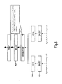
- In order to improve the reception quality at the UE, two techniques are currently under investigation in 3GPP. The general principle of soft and selective combining is the same. Both techniques rely on the reception of the same information from more than one cell. Soft combining is similar to the well-known soft handover scenario already introduced in R99 of UMTS, where a UE combines the soft bits received from several cells at the physical layer provided that the radio links from all cells are sufficiently synchronised in time. In the case of selective combining, the combining process takes place at the RLC layer. The principle of selective combining is shown in
Fig. 5 . With this technique, several links from several cells are received and each link undergoes an independent reception process up to the RLC layer. Therefore the RLC receives several times the same RLC PDUs that are identified by their sequence number (SN). As the different radio links are non-correlated, the probability of receiving correct RLC PDUs increases with the number of radio links. By selecting error-free PDUs from different radio links and combining them, a data stream with lower PDU error rate or error ratio may be obtained. - One of the principal services envisaged for MBMS is file download. With this service, a population (i.e. plurality of UEs) receives simultaneously the same file that can be a game, ring tones, a new application, software upgrades etc. Depending on the charging policy of the operators, it might be necessary to ensure a 100% download success rate of the file whereas with a streaming service some losses may be acceptable as they will only cause some degradation of the quality.
- In order to cope with this, 3GPP SA2 and SA4 are currently specifying an application level procedure, where the UE can require the retransmission of the missing IP packets over a PTP dedicated connection or the complete retransmission of the session.
- From a UTRAN point of view, this procedure cannot be used for fine tuning of the radio network as this information is generated by the application layer at the UE side and its destination should be the peer entity in the operator CN responsible for generating the MBMS data (BM-SC).
- In the document R2-040783 presented by Qualcomm at the 3GPP TSG RAN WG2 MBMS adhoc meeting in Budapest in April 2004, it has been proposed to introduce a reporting mechanism for MBMS where a statistically representative set of UEs receiving MBMS is put in cell_FACH, and these UEs report to the network the transport channel BLER observed. This proposal does not consider the control of the QoS at the RLC layer and does not propose any detailed quality report mechanism.
-
WO 2004/040928 A1 , "Reporting for multi-user services in wireless networks", focuses on a reporting mechanism in the application layer for RTP/RTCP protocols. It does not teach a reporting mechanism between UE and RNC (RRC layer). - In the current state of the MBMS standardisation within 3GPP, no direct QoS control mechanism over the air interface has been developed for a PTM transmission except the point-to-point repair mechanism. However the point-to-point repair mechanism is an application level procedure, which cannot be used to control transmission parameters related to the radio access network (transmission power, code rate, etc). As a matter of fact, in its current state, MBMS relies upon a "blind" transmission, where the transmission parameters are based not on the actual requirements and needs of the receiving stations but on some empiric rules, as no quality feedback reports are sent from the terminals to the radio access network.
- First, no efficient adaptation of the transmission parameters of an MBMS session with respect to the actual terminal requirements is possible. In case of an insufficient transmission power, most of the UEs will receive the MBMS services with a high error rate and, if allowed by the application layer, will require a point-to-point repair session in order to recover the losses. This will create significant traffic in the uplink and in the downlink, which will severely decrease the spectrum efficiency of MBMS. Moreover as the point-to-point repair procedure is an application level procedure, this will be completely transparent to the UTRAN. It will see this traffic as signalling messages designated for the application layer. Therefore the UTRAN will not be able to use this procedure to adapt the radio parameters to the actual MBMS reception quality and will certainly use again the same parameters if another MBMS session with the same characteristics is to be transmitted.
- Another major problem related to the lack of uplink feedback is the limitation in the testing of MBMS capable UEs. In 3GPP, all main functions have to conform to the specifications and shall be tested in order to guarantee a certain quality level. MBMS shall not be an exception to this rule, as new features will be introduced in the lower layers of the UE; reception of high data rate in RRC idle mode, URA_PCH and cell_PCH and cell_FACH modes, MCCH reception, selective combining, inter-frequency measurement in presence of MBMS just to name a few. As MBMS reception shall be provided in all RRC states and in particular in RRC idle mode, a methodology should be derived that would enable the conformance testing of MBMS in this mode. Usually UEs are tested with the help of a special loop back mode, where the DL traffic is directly sent back in the uplink to the test equipment that is simulating the UTRAN. This enables the test equipment to compare the received and processed signal with the original and to easily compute test metrics such as the transport channel BLER. The problem with MBMS in idle, cell_PCH, URA_PCH and also cell_FACH is that there is no uplink or only little bandwidth is available. Therefore it is impossible to carry the envisaged DL MBMS data rates (64kbps to 256kbps services) in the uplink. As a matter of fact, there is today no possibility to test MBMS UEs with the current version of the specifications.
-
US 2003/0207696 A1 relates to Multimedia Broadcast and Multicast Service (MBMS) in a wireless communication system. It provides a method for processing data for a transmission through a plurality of User Equipments. The UEs may be designed with the capability to receive MBMS services via the HSDPA channel structure. However, link adaptation is not performed dynamically for broadcast services, and packet-level feedback from the individual UEs would not be required if appropriate, so that the UEs do not need to report channel quality information or acknowledgement data. - It is therefore the object of the present invention to propose a mechanism for enabling efficient QoS control (by adapting the radio transmission parameters of MBMS) in the radio access network and for also allowing the testing of a specific UE with regard to the new functionalities introduced by MBMS.
- This object is achieved by a method according to claim 1, a mobile terminal according to claim 23, a radio network controller according to claim 25 and a test system according to claim 28. Advantageous embodiments are subject-matter of the dependent claims.
- A new measurement capability in the RLC layer is disclosed which may provide the possibility to control QoS in RLC UM mode when an MBMS service is received over a PTM transmission.
- It is proposed to measure the SDU error rate at the RLC layer in UM when a PTM transmission is used. The SDU error rate is a QoS attribute defined by the CN.
- Such a new measurement has the following benefits in comparison to the existing transport channel BLER control: In MBMS, selective combining might be used and the UE will receive the same MBMS service from several Node Bs. The combining of the different transport channels from the different Node Bs is performed at the RLC layer based on the sequence number of the RLC SDUs. This case implies that several decoding chains from the physical layer up to the point where the combining is performed in the RLC exist in the UE and thus several instances of the same transport channel received from different Node Bs exist in the UE. A quality measurement at the MAC layer (transport channel level) would be very difficult since the number of reports would be equal to the number of cells considered for selective combining. Moreover these values do not give reliable QoS related information, as a high level of transport channel BLER does not necessarily imply a degradation of the QoS. By combining two or more data flows at the RLC layer, the selective combining approach may provide an acceptable RLC SDU error rate despite of the relatively high BLERs.
- By introducing a RLC SDU measurement capability in RLC UM, it is possible for the RNC to adapt the transmission parameters of MBMS. If the RNC collects a significant amount of reports indicating an unacceptable QoS degradation within a specific cell, it might try to improve the situation by either increasing the transmission power of the associated S-CCPCH, change its spreading factor, add more redundancy (decrease the code rate) of the FACH transport channel or change the way the logical channel of interest (e.g MTCH, MCCH) is multiplexed onto transport channels and physical channels. For instance, in case of MCCH, it would be possible to map it exclusively onto a FACH transport channel that is exclusively mapped onto one S-CCPCH.
- Moreover, in order to achieve the required QoS, the RNC could also vary the transmission power or the time offset of the MBMS service of interest in the neighbouring cell or initiate its transmission in order to improve the performance of soft or selective combining.
- This proposal enables also the testing of MBMS capable UEs in non Cell_DCH mode, which will be the most typical case, by transmitting related reports and receiving and evaluating these reports by the test system.
-
Figure 1 shows an overview of UMTS Air Interface Layers. -
Figure 2 depicts the Data transfer in a non-transparent RLC and a transparent MAC sublayer. -
Figure 3 illustrates RRC states and their transitions. -
Figure 4 depicts outer and inner loop downlink power control for FDD. -
Figure 5 illustrates the selective combining principle at the RLC layer. -
Figure 6 shows an embodiment of an RLC error rate measurement capability. -
Figure 7 illustrates the signalling exchange between different layers for the error rate measurement shown inFig. 6 . -
Figure 8 illustrated a conventional RRC connection establishment procedure. -
Figure 9 depicts an anonymous quality measurement report procedure. -
Figure 10 shows a schematic of a mobile terminal (UE) to which the method according to the invention can be applied. -
Figure 11 illustrates a schematic of a RNC which can serve as a counterpart for the mobile terminal shown inFig. 10 . -
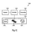
Figure 12 depicts a schematic of a test system which can be used to test a mobile terminal as shown inFigure 10 . - Although the invention is explained below for the example and with the terminology of a UMTS network, it should be understood that this is not limiting. The principle underlying the invention could equally be applied to wireless networks of other standards by replacing UMTS terms with appropriate equivalents.
- A summary of the different new elements is shown in
Figure 6 .Fig.7 depicts the signalling messages exchanged between the different layers. - As explained in the prior art section, no feedback mechanism to the UTRAN exists in the current version of MBMS. The main idea of the invention is to introduce a new measurement capability at the RLC layer in UM when a PTM transmission is used. This measurement is an SDU error rate measurement, as the SDU error rate is a QoS attribute defined by the CN. In PTP mode (over DPCH) this measurement is not needed as there already exists a QoS control mechanism for dedicated connections.
- Referring to
Fig. 6 ,arrow 601 symbolizes a MBMS data transmission from the CN via the RNC and a PTM connection to a population (plurality) of UEs, of which one is shown withreference numeral 403. The MBMS is associated with a set of QoS attributes including a target SDU error rate, which is informed to the RNC by the CN, symbolized byarrow 606. The RLC is configured in un-acknowledged mode for a PTM transmission.UE 403 is configured to provide a SDU error rate measurement capability in itsRLC layer 105. - Although this measurement could have a fixed configuration, it is advantageous to define a downlink broadcast RRC signalling 602 that configures this measurement similar to the RRC MEASUREMENT CONTROL message (see section 8.4.1 and 10.2.17 in 3GPP TS 25.331v6.23.0, cited above). Furthermore this RRC message should be associated to a specific MBMS PTM RAB and broadcast to all UEs potentially receiving the corresponding MBMS service.
- Possible elements of this RRC PTM MBMS QUALITY MEASUREMENT CONTROL message could be
- MBMS service or MBMS PTM RAB identification
- The length of the measurement window in terms of TTI or number of received RLC SDUs
- A quality threshold Q_threshold (for event-triggered measurement) or
- A reporting period (for periodic measurement).
- The measurement control message could also comprise information from which a transmission time of the quality measurement report is derived by the UEs. In this case the exact instance of time would have to be individually randomized by the UEs within a certain interval in order to avoid conflicts in the uplink resources.
- After reception of the measurement control message, the RRC is able to configure the RLC UM by means of a new primitive 603 between the
RRC layer 103 and theRLC layer 105. TheRLC layer 105 in turn informs theRRC layer 103 about the results of the SDU error rate measurement by means of another primitive 604. TheRRC layer 103 is then able to generate aquality measurement report 605 based on the information received from the RLC in the primitive, and to send it to the RNC. - The measurement report may comprise the measured value of the SDU error rate or ratio. Alternatively it may comprise information whether the value exceeds a defined threshold or not. Furthermore the quality measurement report may comprise information about the identity of the MBMS and/or the MTCH. When combining is applied to the MBMS data, the quality measurement report could further comprise information about the type of combining applied, the cells considered or used for combining (i.e. the cells from which MBMS data is received for the purpose of combining), and about the reception quality of the wireless links used for combining (i.e. the SIR of the physical channels or in the case of selective combining the SDU error rates before combining).
-
RNC 402 receives measurement reports from a plurality of UEs receiving the MBMS and can adjust transmission parameters of the MTCH, like transmission power, spreading factor, code rate or multiplexing parameters accordingly in order to secure the QoS of the MBMS as received from the CN. - Referring now to
Fig. 7 , an exemplary timing of the proposed method is illustrated. Firstly, the RNC receives from the CN information about QoS attributes associated with a MBMS broadcast service in the area of the RNC. The RRC layer of the RNC generates a PTM MBMS QUALITY MEASUREMENT CONTROL message and broadcasts it instep 702 in the broadcast area of the MBMS. The message can be either broadcast over BCCH, over CCCH or over MCCH. The latter solution provides the advantage of easier linking between a measurement control message and a specific MBMS service. A particular UE which is also receiving the data from the associated MBMS then receives this message in its RRC layer. Instep 703, the RRC layer sends a primitive to the RLC layer to configure the SDU error rate measurement, which is subsequently executed inbox 704. Although depicted as singular box, this measurement may be repeated for a specified time according to the configuration or until it is disabled by another primitive from the RRC layer. Consequently, one or more primitives are sent from the RLC layer to the RRC layer withstep 705 comprising results from the SDU error rate measurements. Alternatively and depending on the implementation, the RLC layer may prepare a complete measurement report and send it to the RRC layer for transmission to the RNC instep 705. The RRC layer of the UE receives the measurement results or reports, respectively, prepares reports if necessary and decides inbox 706 which reports are to be sent to the RNC withstep 707. - As the main constraints in MBMS concern air capacity and the UE battery power, the quality measurement should only be reported when necessary. Although the measurement report could be configured for periodic transmission, it is advantageous to configure in the RRC a so-called event-triggered measurement. In both options, the UE computes the number of SDUs in error within the measurement window indicated in the configuration message. The number of corrupted SDUs may further be related to the total number of received SDUs in the same measurement window. Alternatively, the erroneous or corrupted SDU segments may be counted and related to the total number of received SDU segments. With an event-triggered measurement, the UE reports its value with
quality measurement report 605 only if a specific threshold (Q_threshold) is exceeded, whereas with a periodic measurement, the UE reports the measurement results periodically. The quality threshold Q_threshold could be either a percentage value or a number of corrupted RLC SDUs that should not to be exceeded within the measurement window. In case of high uplink interference or for other reason, this quality reporting could be disabled by either setting Q_threshold to an infinite value or by not broadcasting the measurement configuration message. In another embodiment, it may be defined that a report is sent when the measured SDU error rate exceeds or falls below the threshold by a pre-defined margin. This provides an additional parameter for a trade-off between efficient use of transmission capacity and transmission reliability. - Periodical reporting could for example be used if the UE already has a connection to the network for some other purpose and can use it to piggyback this measurement report. A UE in CELL_DCH (DCH channels exists in DL and UL) could use the already dedicated connection to send measurement reports to the RNC. In this case it might be interesting to reconfigure the measurement and select a periodic measurement in order to give to the network even more accurate information on the reception quality.
- I another alternative, the CELL update message could also be modified in order to permit UEs in RRC connected mode (except cell_DCH) to report the same information.
Another variant is to reuse the same message for UE in connected mode. In this case the identification of the UE is provided by the dedicated channel used to carry this information (DCCH). - In another advantageous embodiment, an activation command is introduced. The network uses the activation command to request the reporting of the quality measurement that has previously been configured but not activated. This reporting mode could be applied to either an event-triggered measurement or a periodic measurement. It is also possible to de-activate the reporting later by sending a respective command, which might be the activation command with a respective flag reset. Such an activation command could be broadcast over the same channels as the configuration command.
- The computation of the measurement itself for the RLC UM requires no undue processing power or implementation effort, as this can be easily done by using already existing RLC UM functionalities. Indeed the RLC UM shall already check the validity of the SDUs it transmits to the higher layer by using services of the MAC layer such as the CRC check, which indicates if a RLC PDU has been received in error or not and by using the sequence numbering in order to benefit from the selective combining gain. Furthermore, the RLC UM shall discard corrupted RLC SDUs and transmit only the RLC SDUs that are believed to be correct.
- In one alternative the report itself could comprise only a flag, indicating the triggering event (Q_threshold exceeded) or alternatively the actual value of the SDU error rate.
- For the transmission of the report, existing signalling could be reused. If the UE is in RRC idle mode, it has no connection to the network and is completely unknown to the network. Therefore it needs to perform first an RRC establishment connection request procedure and to transit to Cell_FACH mode. A UE in connected mode (URA_PCH, Cell_PCH and Cell_FACH), on the other hand, needs to perform a cell update procedure as it has already an RRC connection with the RNC. An RRC establishment procedure implies intensive signalling between the UE and the RNC over the air interface as shown in
Figure 8 . - In an alternative, advantageous embodiment, anonymous reporting as shown in
Fig. 9 is applied. In this new measurement reporting type the UE sends the quality measurement report to the network in an anonymous fashion. This will enable the UE to send a quality measurement report to the network or to a UE testing equipment in idle mode without changing its RRC mode. Instead of establishing an RRC uplink connection, the UE sends a specific message to the network on a Random Access Channel, RACH, similar to the RRC message "Measured results on RACH" (see section 10.3.7.45 of 3GPP TS 25.331v6.23.0, cited above), where the reception quality of the neighbouring cells is reported. Therefore the identity of the UE does not have to be transmitted to the RNC, and any dedicated channel assignment is unnecessary. Consequently the quality measurement report cannot be associated with the identity of the UE. This is also not necessary, as the quality of a broadcast signal is reported, and the RNC will react on a statistical evaluation of all received quality measurement reports associated with the same MBMS or MTCH. Further teaching regarding anonymous reporting can be found in the co-pending European Patent Application with attorney docket numberEP32466 -
Fig. 10 illustrates the structure of a mobile terminal (UE) 403. A mobile terminal may for example be a conventional mobile phone, a smart phone, or a respective module in any acoustic, video or data processing device. It might even be a module mounted on a vehicle and connected to a processor therein. It comprises areceiver 1001 and acontroller 1002. It may further comprise atransmitter 1006, auser interface 1005 including display, keys and acoustic devices and storage means 1004 for storing executable instructions for thecontroller 1002 as well as any other data. Controller or Controlling means 1002 may comprise one or more processors for protocol interaction, signal processing and control of other components. In order to execute the method according to the present invention,controller 1002 further comprises determiningmeans 1003 for determining the error rate associated with MBMS SDUs received by the RLC in UM. The determining means could be implemented in hardware logic, but will in most cases be implemented in instructions which perform this task when they are executed on a processor of controllingmeans 1002. Controlling means 1002 may further comprise reporting means 1007 (in hardware or executable instructions) for preparing a report comprising information about the results obtained by determiningmeans 1003, and for arranging for its transmission to a RNC 402 (i.e. the entity controlling the radio link for the downlink data transmission) viatransmitter 1006. - Instructions which cause controlling means 1002 to carry out the methods described above can be stored in a non-volatile part of storage means 1004, for example read only memory (ROM), programmable read only memory (PROM), EPROM, EEPROM or FLASH. The instructions may be loaded to such semiconductor storage media from other computer-readable storage media like magnetic disk, magnetic tape or optical disk.
-
Fig. 11 illustrates aRNC 402 which could act as a counterpart toUE 403. It comprises atransmitter interface 1101 to connect it to atransmitter 1105, areceiver interface 1102 to connect it to areceiver 1106, acore network interface 1103 to connect it to aCN 401 and controlling means or acontroller 1104 which controls the interfaces and performs protocol tasks and signal processing.Controller 1104 is configured, by special hardware or by instructions executed on a processor, to receive MBMS data and associated QoS informationform core network 401 viaCN interface 1103 and to establish a PTM connection on the MTCH for the MBMS.Controller 1104 further generates a measurement control message as described further above and arranges for its broadcasting viatransmitter interface 1101 andtransmitter 1105. It receives quality measurement reports from UEs viareceiver 1106 andreceiver interface 1102 and adjusts transmission parameters of the MTCH carrying the MBMS accordingly in order to provide the QoS as specified in the information received fromCN 401 viacore network interface 1103. -
Fig. 12 illustrates atest system 1200 for testing MBMS related functionality of UEs. It comprises atransmitter 1201, areceiver 1202, a controller or controllingmeans 1203 anduser interface 1204 comprising for example a LCD orCRT screen 1205, akeyboard 1206 and aprinter 1207.Test system 1200 behaves more or less like aRAN comprising RNC 402 described in the section above. However, contrary to the functionality of the RNC as described above,tester 1200 does not adjust transmission parameters for the MBMS based on the measurement reports from the UE under test. Instead it prepares a test report about the UE, based on the information comprised in the received measurement reports and outputs the test report viauser interface 1204. To this end it also may vary systematically various kinds of transmission parameters, add noise or simulate propagation effects like fading in order to test the behaviour of the UE under these conditions. - Appendix: Abbreviations
Abbreviation Description 3GPP 3rd Generation Partnership Project AM Acknowledged Mode BCCH Broadcast Control Channel BCH Broadcast Channel BLER Block Error Ratio BMC Broadcast / Multicast Control BM-SC Broadcast-Multicast Service Centre CBS Cell Broadcast Service CCCH Common Control Channel CN Core Network CS Circuit Switched DCCH Dedicated Control Channel DCH Dedicated Channel DL Downlink DPCH Dedicated Physical Channel DPDCH Dedicated Physical Data Channel DRX Discontinuous Reception FACH Forward Access Channel FDD Frequency Division Duplex HSDPA High Speed Downlink Packet Access IE Information Element LA Location Area MAC Medium Access Control MBMS Multimedia Broadcast Multicast Service MCCH MBMS Control Channel MTCH MBMS Traffic Channel PCH Paging Channel PDCP Packet Data Convergence Protocol PDU Protocol Data Unit PICH Page Indicator Channel PTM point-to-multipoint transmission PTP point-to-point transmission QoS Quality of Service RA Registration Area RAB Radio Access Bearer RACH Random Access Channel RAN Radio Access Network RANAP Radio Access Network Application Part RB Radio Bearer RLC Radio Link Control RNC Radio Network Controller RRC Radio Resource Control S-CCPCH Secondary Common Control Physical Channel SDU Service Data Unit SIR Signal-to-Interference Ratio SN Sequence Number SRB Signalling Radio Bearer TCP Transmission Control Protocol TM Transparent Mode TPC Transmission Power Control TrCH Transport Channel TTI Transmission Timing Interval UE User Equipment UM Un-acknowledged Mode UMTS Universal Mobile Telecommunications System URA User Registration Area, UTRAN Registration Area UTRAN Universal Terrestrial Radio Access Network VolP Voice over Internet Protocol
Claims (28)
- A method for controlling the quality of service of a broadcast or multicast service in a mobile terminal of a wireless communication system, comprising the steps of:a) receiving service data units via a wireless link of the communication system; andb) determining an error rate associated with said service data units (704),
characterized in that
said step b) is carried out in a radio link control layer in unacknowledged data transfer mode, and
after step b), by a step c) (707) of sending a measurement report based on said error rate to an entity controlling said wireless link, and
by adjusting transmission parameters of the transmission of said service data units based on said measurement report. - The method according to claim 1, wherein said error rate is a ratio of a number of corrupted service data units received in a given time interval to a total number of service data units received in the same time interval.
- The method according to claim 1, wherein said service data units are segmented for transmission via said wireless link, and said error rate is a ratio of a number of corrupted service data unit segments received in a given time interval to a total number of service data unit segments received in the same time interval.
- The method according to one of claims 1 to 3, wherein said report is sent by establishing an uplink connection in said wireless communication system from said mobile terminal to said controlling entity.
- The method according to one of claims 1 to 3, wherein said report cannot be associated with an identity of said mobile terminal by said entity.
- The method according to one of the claims 1 to 5, wherein said measurement report comprises a value associated with said determined error rate.
- The method according to one of the claims 1 to 5, wherein said measurement report comprises information whether said error rate exceeds a defined threshold.
- The method according to one of the claims 1 to 7, further comprising, before step a), a step d) (702) of receiving a message comprising configuration information concerning at least one of said determining step b) and said sending step c).
- The method according to claim 8, wherein said message is received from a multimedia broadcast multicast service control channel, a broadcast control channel or a common control channel.
- The method according to one of the claims 1 to 9, further comprising, prior to said step c), a step e) of receiving an activation command, wherein said measurement report is sent only after activation by said activation command.
- The method according to one of the claims 8 to 10, wherein said measurement report is sent at a time derived from information comprised in said message.
- The method according to one of the claims 1 to 10, wherein said measurement report is sent periodically.
- The method according to one of the claims 1 to 10, wherein said measurement report is sent when said error rate exceeds a pre-defined threshold.
- The method according to claim 7 or 13, wherein said threshold is derived from a quality of service attribute associated with said broadcast or multicast service.
- The method according to claim 14, wherein said threshold is equal to said quality of service attribute.
- The method according to claim 14, wherein said threshold is below or above said quality of service attribute by a pre-defined margin.
- The method according to one of the preceding claims, further comprising the steps of
sending, before step b), a primitive for the configuration of an error rate measurement from a radio resource control layer of the same mobile terminal to the radio link control layer (703); and
sending, after step b), a primitive from the radio link control layer to the radio resource control layer (705) comprising a value representing the result of said determining step b). - The method according to one of the claims 1 to 17, further comprising, before step b), the steps off) receiving service data units of said broadcast or multicast service via at least one more wireless link of the communication system; andg) combining data received in step f) via different wireless links and carrying the same information.
- The method of claim 18, wherein said report further comprises information about a type of said combining.
- The method according to claim 18 or 19, wherein said report comprises information on cells considered for said combining.
- The method according to one of the claims 18 to 20, wherein said report comprises information on a reception quality of one or more cells considered for said combining.
- A computer-readable storage medium, having stored thereon instructions, which, when executed on a processor of a mobile terminal cause the mobile terminal to perform the method according to one of the claims 1 to 21.
- A mobile terminal (403) for use in a wireless communication system, comprising:receiving means (1001) for receiving service data units via said wireless communication system; andcontrolling means (1002) adapted to control said receiving means,said controlling means (1002) comprising determining means (1003) for determining an error rate associated with said service data units,characterized in that
the determining means is adapted to determine the error rate in a radio link control layer in an unacknowledged data transfer mode, and
the mobile terminal is adapted to send a measurement report based on said error rate to an entity controlling said wireless link. - The mobile terminal according to claim 23, wherein said determining means (1003) is configured to determine a ratio of a number of corrupted service data units received in a given time interval to a total number of service data units received in the same time interval, as said error rate.
- A radio network controller (402) for use in a wireless communication system, comprising:a transmitter interface (1101) for connecting it to at least one transmitter (1105);a receiver interface (1102) for connecting it to at least one receiver (1106);a core network interface (1103) for connecting it to a core network (401) of said wireless communication system; andcontrolling means (1104) for controlling said interfaces (1101, 1102, 1103), said transmitter (1105) and said receiver (1106),said radio network controller (402) being further configuredto establish a multimedia broadcast multicast service in said wireless communication system by transmitting service data units via said transmitter (1105);to transmit a message via said transmitter (1105), the message comprising configuration information concerning the generation in a radio link control layer in unacknowledged mode of a measurement report based on an error rate associated with said service data units ;to receive reports about error rates associated with said service data units via said receiver (1106); andto adapt transmission parameters for the transmission of said service data units depending on information comprised within said reports,wherein said reports comprise information about an error rate associated with said service data units.
- The radio network controller (402) according to claim 25, wherein said transmission parameters comprise a transmission power, a spreading factor, a code rate or multiplexing parameters.
- A wireless communication system comprising
at least one mobile terminal (403) according to claim 23 or 24 and
a radio network controller (402) according to claim 25 or 26. - A test system (1200) for the test of a mobile terminal (403), comprising:a transmitter (1201) for sending data to said mobile terminal (403);a receiver (1202) for receiving data from said mobile terminal (403);controlling means (1203) adapted to control said receiver (1202) and said transmitter (1201); anda user interface (1204) for controlling functions of the test system and for outputting test results,said controlling means (1203) being further configuredto establish a multimedia broadcast multicast service to said mobile terminal by transmitting service data units via said transmitter (1201);to transmit a message to said mobile terminal (403) via said transmitter (1201), the message comprising configuration information concerning the generation in a radio link control layer in unacknowledged mode of a measurement report based on an error rate associated with said service data units;to receive reports via said receiver (1202) from said mobile terminal, UE, about error rates associated with said service data units; andto output a test report via said user interface, based on information comprised within said reports,wherein said reports comprise information about an error rate associated with said service data units.
Priority Applications (8)
| Application Number | Priority Date | Filing Date | Title |
|---|---|---|---|
| EP04022968A EP1641189B1 (en) | 2004-09-27 | 2004-09-27 | Error ratio measurement in the radio link control layer for quality of service control in a wireless communication system |
| DE602004027247T DE602004027247D1 (en) | 2004-09-27 | 2004-09-27 | Error rate measurement in the radio link control layer for controlling the quality of service of a wireless communication system |
| AT04022968T ATE468685T1 (en) | 2004-09-27 | 2004-09-27 | ERROR RATE MEASUREMENT IN THE RADIO LINK CONTROL LAYER FOR CONTROLLING THE QUALITY OF SERVICE OF A WIRELESS COMMUNICATIONS SYSTEM |
| PCT/EP2005/010284 WO2006034818A1 (en) | 2004-09-27 | 2005-09-22 | Error ratio measurement in the radio link control layer for quality of service control in a wireless communication system |
| JP2007532838A JP4787837B2 (en) | 2004-09-27 | 2005-09-22 | Error ratio measurement at radio link control layer for quality measurement in wireless communication system |
| US11/575,937 US20080076359A1 (en) | 2004-09-27 | 2005-09-22 | Error Ratio Measurement in the Radio Link Control Layer for Quality of Service Control in a Wireless Communication System |
| BRPI0516287-4A BRPI0516287A (en) | 2004-09-27 | 2005-09-22 | method for controlling the quality of service of a transmission or broadcast service on a mobile terminal of a wireless communication system, computer readable storage media, mobile terminal for use in a wireless communication system, controller network radio for use in a wireless communication system, wireless communication system and testing system for testing a mobile terminal |
| CNA2005800326236A CN101053221A (en) | 2004-09-27 | 2005-09-22 | Error ratio measurement in the radio link control layer for quality of service control in a wireless communication system |
Applications Claiming Priority (1)
| Application Number | Priority Date | Filing Date | Title |
|---|---|---|---|
| EP04022968A EP1641189B1 (en) | 2004-09-27 | 2004-09-27 | Error ratio measurement in the radio link control layer for quality of service control in a wireless communication system |
Publications (2)
| Publication Number | Publication Date |
|---|---|
| EP1641189A1 EP1641189A1 (en) | 2006-03-29 |
| EP1641189B1 true EP1641189B1 (en) | 2010-05-19 |
Family
ID=34926728
Family Applications (1)
| Application Number | Title | Priority Date | Filing Date |
|---|---|---|---|
| EP04022968A Not-in-force EP1641189B1 (en) | 2004-09-27 | 2004-09-27 | Error ratio measurement in the radio link control layer for quality of service control in a wireless communication system |
Country Status (8)
| Country | Link |
|---|---|
| US (1) | US20080076359A1 (en) |
| EP (1) | EP1641189B1 (en) |
| JP (1) | JP4787837B2 (en) |
| CN (1) | CN101053221A (en) |
| AT (1) | ATE468685T1 (en) |
| BR (1) | BRPI0516287A (en) |
| DE (1) | DE602004027247D1 (en) |
| WO (1) | WO2006034818A1 (en) |
Cited By (4)
| Publication number | Priority date | Publication date | Assignee | Title |
|---|---|---|---|---|
| US8570956B2 (en) | 2006-06-21 | 2013-10-29 | Lg Electronics Inc. | Method of communicating data in a wireless mobile communications system using message separation and mobile terminal for use with the same |
| US8638707B2 (en) | 2006-06-21 | 2014-01-28 | Lg Electronics Inc. | Method for supporting quality of multimedia broadcast multicast service (MBMS) in mobile communications system and terminal thereof |
| US8644250B2 (en) | 2006-01-05 | 2014-02-04 | Lg Electronics Inc. | Maintaining communication between mobile terminal and network in mobile communication system |
| US8971288B2 (en) | 2006-03-22 | 2015-03-03 | Lg Electronics Inc. | Method of supporting handover in a wireless communication system |
Families Citing this family (69)
| Publication number | Priority date | Publication date | Assignee | Title |
|---|---|---|---|---|
| CN1286332C (en) * | 2004-08-12 | 2006-11-22 | 华为技术有限公司 | MBMS service transmission method |
| US8488459B2 (en) * | 2005-03-04 | 2013-07-16 | Qualcomm Incorporated | Power control and quality of service (QoS) implementation in a communication system |
| WO2007078171A2 (en) | 2006-01-05 | 2007-07-12 | Lg Electronics Inc. | Method of transmitting feedback information in a wireless communication system |
| JP4806030B2 (en) * | 2006-01-05 | 2011-11-02 | エルジー エレクトロニクス インコーポレイティド | Method for transferring signals in a mobile communication system |
| GB2434714A (en) * | 2006-01-26 | 2007-08-01 | Nec Technologies | Inter-frequency measurement |
| US8190197B2 (en) * | 2006-03-10 | 2012-05-29 | Nec Corporation | Portable telephone and communication mode setting method |
| GB0611684D0 (en) * | 2006-06-13 | 2006-07-26 | Nokia Corp | Communications |
| CN101507326B (en) * | 2006-06-20 | 2013-03-13 | 株式会社Ntt都科摩 | Communication method |
| US7660606B2 (en) * | 2006-06-29 | 2010-02-09 | Alcatel-Lucent Usa Inc. | Method of controlling mobile unit response messages on an access channel |
| US20080212615A1 (en) * | 2006-07-10 | 2008-09-04 | Ranta-Aho Karri | Method and Apparatus for Communicating Data in a Communications System |
| US20080008097A1 (en) * | 2006-07-10 | 2008-01-10 | Phani Bhushan Avadhanam | Methods and apparatus for providing measurement reports in a network environment |
| FR2905044B1 (en) * | 2006-08-17 | 2012-10-26 | Cit Alcatel | DEVICE FOR ADAPTING MODULATION SCHEME (S) AND ENCODING DATA FOR DISTRIBUTION TO RADIO COMMUNICATION TERMINALS |
| FR2905045B1 (en) * | 2006-08-17 | 2011-09-02 | Cit Alcatel | PROCESSING DEVICE FOR TRANSMITTING MEASUREMENTS EFFECTED BY RADIO TERMINALS |
| EP1890408A3 (en) * | 2006-08-18 | 2011-10-12 | Samsung Electronics Co., Ltd. | Method and apparatus for reporting reception ratio of streaming service by terminal in a mobile broadcasting system, and system thereof |
| US8369860B2 (en) | 2006-08-18 | 2013-02-05 | Interdigital Technology Corporation | Sending and reducing uplink feedback signaling for transmission of MBMS data |
| KR101265643B1 (en) | 2006-08-22 | 2013-05-22 | 엘지전자 주식회사 | A mothod of executing handover and controlling thereof in mobile communication system |
| WO2008038104A2 (en) * | 2006-09-25 | 2008-04-03 | Nokia Corporation | Threshold based uplink feedback signallin |
| US8619685B2 (en) | 2006-10-02 | 2013-12-31 | Lg Electronics Inc. | Method for transmitting and receiving paging message in wireless communication system |
| EP2084928B1 (en) * | 2006-10-30 | 2017-08-23 | LG Electronics Inc. | Method of performing random access in a wireless communication system |
| EP2078342B1 (en) * | 2006-10-30 | 2015-08-26 | LG Electronics Inc. | Method for transmitting random access channel message and response message, and mobile communication terminal |
| KR100938754B1 (en) | 2006-10-30 | 2010-01-26 | 엘지전자 주식회사 | Data transmission method and data receiving method using discontinuous reception |
| BRPI0807058A2 (en) * | 2007-02-05 | 2020-08-11 | Telefonaktiebolaget Lm Ericsson [Publ] | methods for configuring user equipment on a radio base station of a telecommunication network and for performing downlink measurements on one or more cells on a user equipment, radio base station of a mobile telecommunication network, and, equipment over a mobile telecommunication network |
| MX2009009894A (en) * | 2007-03-16 | 2009-11-23 | Interdigital Tech Corp | Method and apparatus for high speed downlink packet access link adaptation. |
| US8184570B2 (en) * | 2007-04-30 | 2012-05-22 | Lg Electronics Inc. | Method of transmitting data in wireless communication system supporting multimedia broadcast/multicast service |
| USRE45347E1 (en) | 2007-04-30 | 2015-01-20 | Lg Electronics Inc. | Methods of transmitting data blocks in wireless communication system |
| KR101464748B1 (en) * | 2007-04-30 | 2014-11-24 | 엘지전자 주식회사 | Method for triggering a measurement report of mobile terminal |
| KR101469281B1 (en) * | 2007-04-30 | 2014-12-04 | 엘지전자 주식회사 | Method for state transition of mobile terminal |
| KR101386812B1 (en) | 2007-04-30 | 2014-04-29 | 엘지전자 주식회사 | Methods for transmitting or receiving data unit(s) using a header field existence indicator |
| WO2008133481A1 (en) | 2007-04-30 | 2008-11-06 | Lg Electronics Inc. | Method for performing an authentication of entities during establishment of wireless call connection |
| JP2008278339A (en) * | 2007-05-01 | 2008-11-13 | Ntt Docomo Inc | Base station apparatus and communication control method |
| KR20080097338A (en) * | 2007-05-01 | 2008-11-05 | 엘지전자 주식회사 | Discontinuous data transmittion/reception method |
| KR100917205B1 (en) | 2007-05-02 | 2009-09-15 | 엘지전자 주식회사 | Method of configuring a data block in wireless communication system |
| US20080274759A1 (en) * | 2007-05-04 | 2008-11-06 | Hongyuan Chen | System and Method for Controlling Base Stations for Multimedia Broadcast Communications |
| EP2015478B1 (en) * | 2007-06-18 | 2013-07-31 | LG Electronics Inc. | Method of performing uplink synchronization in wireless communication system |
| WO2008156308A2 (en) | 2007-06-18 | 2008-12-24 | Lg Electronics Inc. | Paging information transmission method for effective call setup |
| GB0711833D0 (en) * | 2007-06-18 | 2007-07-25 | Nokia Siemens Networks Oy | A method for providing a plurality of services |
| CN101755475B (en) * | 2007-06-19 | 2014-03-12 | 诺基亚公司 | Apparatus, method and computer program product providing idle mode discontinuous reception |
| IL203785A (en) | 2007-09-12 | 2014-07-31 | Qualcomm Inc | Capacity increasing devices and methods for wireless communication |
| CN102664847B (en) * | 2007-09-12 | 2016-04-20 | 高通股份有限公司 | For equipment and the method for the capacity increasing of radio communication |
| KR101387537B1 (en) * | 2007-09-20 | 2014-04-21 | 엘지전자 주식회사 | A method for handling correctly received but header compression failed packets |
| US8532683B2 (en) | 2007-10-01 | 2013-09-10 | Nokia Corporation | Simple distributed coordination among cells to achieve efficient dynamic single-frequency network (SFN) operation |
| CN101515856B (en) * | 2008-02-20 | 2011-12-07 | 中兴通讯股份有限公司 | Method for transmitting multicast services of multimedia broadcast in nontransparent relay station mode |
| CN101583199B (en) * | 2008-05-15 | 2010-12-08 | 大唐移动通信设备有限公司 | Method and device for assigning physical layer mark of cell |
| WO2009145684A1 (en) * | 2008-05-26 | 2009-12-03 | Telefonaktiebolaget L M Ericsson (Publ) | A method of requesting cqi reports |
| EP2139179A1 (en) * | 2008-06-26 | 2009-12-30 | THOMSON Licensing | Method and apparatus for reporting state information |
| EP2315481A4 (en) * | 2008-08-11 | 2015-05-13 | Ntt Docomo Inc | User device and method for determining downlink synchronization for user device |
| WO2010051838A1 (en) * | 2008-11-05 | 2010-05-14 | Nokia Siemens Networks Oy | Method of improving coverage and optimisation in communication networks |
| US20100135326A1 (en) * | 2008-11-21 | 2010-06-03 | Qualcomm Incorporated | Technique for bundle creation |
| US8548485B2 (en) * | 2009-03-26 | 2013-10-01 | Qualcomm Incorporated | Methods and systems for adaptive broadcasting and multicasting in a wireless network |
| US8687591B2 (en) * | 2009-04-27 | 2014-04-01 | Qualcomm Incorporated | Relay node user plane support |
| EP2426959B1 (en) * | 2009-04-29 | 2015-11-11 | Alcatel Lucent | Mbms service transmission method and device |
| KR20100135468A (en) | 2009-06-17 | 2010-12-27 | 삼성전자주식회사 | Device and method for transmitting multimedia data in wireless communication system |
| CN101646189B (en) * | 2009-08-28 | 2012-11-21 | 华为技术有限公司 | Wireless network cell performance test method and device |
| SG176323A1 (en) * | 2010-05-17 | 2011-12-29 | Creative Tech Ltd | Methods for increasing a number of media playback devices served by a communications base station |
| CN102300159B (en) * | 2010-06-24 | 2016-06-01 | 中兴通讯股份有限公司 | The processing method of multimedia broadcast multicast service, system and subscriber equipment |
| EP2676476B1 (en) * | 2011-02-16 | 2018-10-31 | Nokia Solutions and Networks Oy | Radio link control |
| CN102438265B (en) * | 2012-01-17 | 2014-12-17 | 大唐移动通信设备有限公司 | Test method and device for RLC (Radio Link Control) layer |
| IN2014DN09236A (en) * | 2012-05-10 | 2015-07-10 | Nokia Solutions & Networks Oy | |
| CN103079218B (en) * | 2013-01-10 | 2016-01-27 | 大唐移动通信设备有限公司 | Auto-dial testing control method and equipment |
| US9479294B2 (en) * | 2013-07-15 | 2016-10-25 | Alcatel Lucent | Wireless transmission control for improved aggregated cell throughput capacity and signaling reliability |
| US9699669B2 (en) | 2014-04-28 | 2017-07-04 | Intel IP Corporation | Storing a value of a counter for a wireless local area network |
| US10841203B2 (en) * | 2015-12-11 | 2020-11-17 | Qualcomm Incorporated | Coordination of multiple routes for a single IP connection |
| US20210051482A1 (en) * | 2018-02-16 | 2021-02-18 | Nec Corporation | Integrity protection for user plane data in 5g network |
| US11596016B2 (en) * | 2018-04-06 | 2023-02-28 | Apple Inc. | Enhancing latency and throughput in LTE and in an asymmetric EN-DC configuration |
| CN111356131B (en) * | 2018-12-20 | 2022-04-29 | 华为技术有限公司 | Communication method, device and system |
| US11330668B2 (en) * | 2019-11-22 | 2022-05-10 | Apple Inc. | 5G NR FR2 beam management enhancements |
| CN114902568A (en) * | 2019-12-19 | 2022-08-12 | 诺基亚技术有限公司 | Protocol Data Unit (PDU) error probability feedback |
| CN116250255A (en) | 2020-08-06 | 2023-06-09 | 中兴通讯股份有限公司 | Multicast and broadcast service status reporting |
| US11665584B2 (en) * | 2021-04-28 | 2023-05-30 | Qualcomm Incorporated | Radio link control forward compatibility for multicast messages or broadcast messages |
Family Cites Families (17)
| Publication number | Priority date | Publication date | Assignee | Title |
|---|---|---|---|---|
| US5278834A (en) * | 1992-05-26 | 1994-01-11 | Alcatel Network Systems, Inc. | Method for implementing a data communication protocol stack |
| JP3660690B2 (en) * | 1996-06-27 | 2005-06-15 | 株式会社エヌ・ティ・ティ・ドコモ | Transmission power control device |
| US6542490B1 (en) * | 1999-01-29 | 2003-04-01 | Nortel Networks Limited | Data link control proctocol for 3G wireless system |
| FI990690A (en) * | 1999-03-29 | 2000-09-30 | Nokia Mobile Phones Ltd | Method and arrangement for testing the functionality of data transmission in a radio |
| FR2809577B1 (en) * | 2000-05-25 | 2002-10-18 | Mitsubishi Electric Inf Tech | DATA TRANSMISSION METHOD COMBATING THE DEGRADATION OF QUALITY OF SERVICE |
| KR100640921B1 (en) * | 2000-06-29 | 2006-11-02 | 엘지전자 주식회사 | Method for Generating and Transmitting Protocol Data Unit |
| US7668176B2 (en) * | 2001-01-18 | 2010-02-23 | Alcatel-Lucent Usa Inc. | Universal mobile telecommunications system (UMTS) quality of service (QoS) supporting variable QoS negotiation |
| US7787389B2 (en) * | 2001-08-20 | 2010-08-31 | Qualcomm Incorporated | Method and system for utilization of an outer decoder in a broadcast services communication system |
| US7177658B2 (en) * | 2002-05-06 | 2007-02-13 | Qualcomm, Incorporated | Multi-media broadcast and multicast service (MBMS) in a wireless communications system |
| US20030210714A1 (en) * | 2002-05-10 | 2003-11-13 | Chih-Hsiang Wu | Method for avoiding loss of pdcp pdus in a wireless communications system |
| EP1372310A1 (en) * | 2002-06-12 | 2003-12-17 | Motorola, Inc. | Apparatus and method for communicating data using header compression |
| KR20040040724A (en) * | 2002-11-07 | 2004-05-13 | 엘지전자 주식회사 | Up-link common channel and operation method of it in a mobile radio communication system |
| US7970423B2 (en) * | 2002-11-08 | 2011-06-28 | Nokia Corporation | Context linking scheme |
| KR100651405B1 (en) * | 2003-07-24 | 2006-11-29 | 삼성전자주식회사 | Apparatus and method for transmission/reception of control information mbms mobile communication |
| US7586948B2 (en) * | 2003-12-24 | 2009-09-08 | Agere Systems Inc. | Packet sub-frame structure for selective acknowledgment |
| ATE538554T1 (en) * | 2005-08-16 | 2012-01-15 | Panasonic Corp | METHOD AND DEVICES FOR RESETTING A TRANSMIT SEQUENCE NUMBER (TSN) |
| CN103490853B (en) * | 2007-09-28 | 2017-06-27 | 交互数字专利控股公司 | A kind of method and wireless transmitter/receiver unit for producing and transmitting RLC PDU |
-
2004
- 2004-09-27 AT AT04022968T patent/ATE468685T1/en not_active IP Right Cessation
- 2004-09-27 DE DE602004027247T patent/DE602004027247D1/en active Active
- 2004-09-27 EP EP04022968A patent/EP1641189B1/en not_active Not-in-force
-
2005
- 2005-09-22 US US11/575,937 patent/US20080076359A1/en not_active Abandoned
- 2005-09-22 JP JP2007532838A patent/JP4787837B2/en not_active Expired - Fee Related
- 2005-09-22 WO PCT/EP2005/010284 patent/WO2006034818A1/en active Application Filing
- 2005-09-22 BR BRPI0516287-4A patent/BRPI0516287A/en not_active IP Right Cessation
- 2005-09-22 CN CNA2005800326236A patent/CN101053221A/en active Pending
Cited By (5)
| Publication number | Priority date | Publication date | Assignee | Title |
|---|---|---|---|---|
| US8644250B2 (en) | 2006-01-05 | 2014-02-04 | Lg Electronics Inc. | Maintaining communication between mobile terminal and network in mobile communication system |
| US9253801B2 (en) | 2006-01-05 | 2016-02-02 | Lg Electronics Inc. | Maintaining communication between mobile terminal and network in mobile communication system |
| US8971288B2 (en) | 2006-03-22 | 2015-03-03 | Lg Electronics Inc. | Method of supporting handover in a wireless communication system |
| US8570956B2 (en) | 2006-06-21 | 2013-10-29 | Lg Electronics Inc. | Method of communicating data in a wireless mobile communications system using message separation and mobile terminal for use with the same |
| US8638707B2 (en) | 2006-06-21 | 2014-01-28 | Lg Electronics Inc. | Method for supporting quality of multimedia broadcast multicast service (MBMS) in mobile communications system and terminal thereof |
Also Published As
| Publication number | Publication date |
|---|---|
| CN101053221A (en) | 2007-10-10 |
| WO2006034818A1 (en) | 2006-04-06 |
| EP1641189A1 (en) | 2006-03-29 |
| DE602004027247D1 (en) | 2010-07-01 |
| JP4787837B2 (en) | 2011-10-05 |
| US20080076359A1 (en) | 2008-03-27 |
| BRPI0516287A (en) | 2008-09-02 |
| JP2008515256A (en) | 2008-05-08 |
| ATE468685T1 (en) | 2010-06-15 |
Similar Documents
| Publication | Publication Date | Title |
|---|---|---|
| EP1641189B1 (en) | Error ratio measurement in the radio link control layer for quality of service control in a wireless communication system | |
| EP1641302B1 (en) | Anonymous uplink measurement report in a wireless communication system | |
| JP4484932B2 (en) | How to resolve radio link control errors | |
| TWI418229B (en) | Method and apparatus for communicating control information in mobile communication system | |
| JP4696161B2 (en) | Effective radio resource management method | |
| JP5055633B2 (en) | User equipment | |
| TWI423605B (en) | Device and method for communications, communications system, and article of manufacture comprising a non-transitory computer-readable medium | |
| CN102333383B (en) | Transmission/receiving method and device for high-speed downlink packet access related channel | |
| KR100595646B1 (en) | Radio communication system providing mbms | |
| JP4510026B2 (en) | Method and apparatus for inter-frequency / RAT handover measurement in MBMS | |
| MX2007012169A (en) | Multimedia broadcast/multicast service cells reconfigurations. | |
| CA2715986A1 (en) | Method for transmitting pdcp status report | |
| EP2127438B1 (en) | Discontinuous reception operation during continuous transmission | |
| US8411697B2 (en) | Method and arrangement for improving media transmission quality using robust representation of media frames | |
| EP1984917A2 (en) | Method and arrangement for improving media transmission quality | |
| Assaad et al. | Universal Mobile for Telecommunication Systems | |
| KR20060115292A (en) | A method and apparatus for scheduling of mobile station in soft hand-over area for up-link packet transmission |
Legal Events
| Date | Code | Title | Description |
|---|---|---|---|
| PUAI | Public reference made under article 153(3) epc to a published international application that has entered the european phase |
Free format text: ORIGINAL CODE: 0009012 |
|
| AK | Designated contracting states |
Kind code of ref document: A1 Designated state(s): AT BE BG CH CY CZ DE DK EE ES FI FR GB GR HU IE IT LI LU MC NL PL PT RO SE SI SK TR |
|
| AX | Request for extension of the european patent |
Extension state: AL HR LT LV MK |
|
| 17P | Request for examination filed |
Effective date: 20060929 |
|
| AKX | Designation fees paid |
Designated state(s): AT BE BG CH CY CZ DE DK EE ES FI FR GB GR HU IE IT LI LU MC NL PL PT RO SE SI SK TR |
|
| 17Q | First examination report despatched |
Effective date: 20070417 |
|
| RAP1 | Party data changed (applicant data changed or rights of an application transferred) |
Owner name: PANASONIC CORPORATION |
|
| RIC1 | Information provided on ipc code assigned before grant |
Ipc: H04L 12/18 20060101ALI20090728BHEP Ipc: H04L 12/56 20060101AFI20090728BHEP Ipc: H04W 24/00 20090101ALI20090728BHEP |
|
| GRAP | Despatch of communication of intention to grant a patent |
Free format text: ORIGINAL CODE: EPIDOSNIGR1 |
|
| GRAS | Grant fee paid |
Free format text: ORIGINAL CODE: EPIDOSNIGR3 |
|
| GRAA | (expected) grant |
Free format text: ORIGINAL CODE: 0009210 |
|
| AK | Designated contracting states |
Kind code of ref document: B1 Designated state(s): AT BE BG CH CY CZ DE DK EE ES FI FR GB GR HU IE IT LI LU MC NL PL PT RO SE SI SK TR |
|
| REG | Reference to a national code |
Ref country code: GB Ref legal event code: FG4D |
|
| REG | Reference to a national code |
Ref country code: CH Ref legal event code: EP |
|
| REG | Reference to a national code |
Ref country code: IE Ref legal event code: FG4D |
|
| REF | Corresponds to: |
Ref document number: 602004027247 Country of ref document: DE Date of ref document: 20100701 Kind code of ref document: P |
|
| REG | Reference to a national code |
Ref country code: NL Ref legal event code: VDEP Effective date: 20100519 |
|
| PG25 | Lapsed in a contracting state [announced via postgrant information from national office to epo] |
Ref country code: SE Free format text: LAPSE BECAUSE OF FAILURE TO SUBMIT A TRANSLATION OF THE DESCRIPTION OR TO PAY THE FEE WITHIN THE PRESCRIBED TIME-LIMIT Effective date: 20100519 Ref country code: ES Free format text: LAPSE BECAUSE OF FAILURE TO SUBMIT A TRANSLATION OF THE DESCRIPTION OR TO PAY THE FEE WITHIN THE PRESCRIBED TIME-LIMIT Effective date: 20100830 |
|
| PG25 | Lapsed in a contracting state [announced via postgrant information from national office to epo] |
Ref country code: AT Free format text: LAPSE BECAUSE OF FAILURE TO SUBMIT A TRANSLATION OF THE DESCRIPTION OR TO PAY THE FEE WITHIN THE PRESCRIBED TIME-LIMIT Effective date: 20100519 Ref country code: SI Free format text: LAPSE BECAUSE OF FAILURE TO SUBMIT A TRANSLATION OF THE DESCRIPTION OR TO PAY THE FEE WITHIN THE PRESCRIBED TIME-LIMIT Effective date: 20100519 Ref country code: FI Free format text: LAPSE BECAUSE OF FAILURE TO SUBMIT A TRANSLATION OF THE DESCRIPTION OR TO PAY THE FEE WITHIN THE PRESCRIBED TIME-LIMIT Effective date: 20100519 |
|
| PG25 | Lapsed in a contracting state [announced via postgrant information from national office to epo] |
Ref country code: GR Free format text: LAPSE BECAUSE OF FAILURE TO SUBMIT A TRANSLATION OF THE DESCRIPTION OR TO PAY THE FEE WITHIN THE PRESCRIBED TIME-LIMIT Effective date: 20100820 Ref country code: CY Free format text: LAPSE BECAUSE OF FAILURE TO SUBMIT A TRANSLATION OF THE DESCRIPTION OR TO PAY THE FEE WITHIN THE PRESCRIBED TIME-LIMIT Effective date: 20100519 Ref country code: PL Free format text: LAPSE BECAUSE OF FAILURE TO SUBMIT A TRANSLATION OF THE DESCRIPTION OR TO PAY THE FEE WITHIN THE PRESCRIBED TIME-LIMIT Effective date: 20100519 |
|
| PG25 | Lapsed in a contracting state [announced via postgrant information from national office to epo] |
Ref country code: NL Free format text: LAPSE BECAUSE OF FAILURE TO SUBMIT A TRANSLATION OF THE DESCRIPTION OR TO PAY THE FEE WITHIN THE PRESCRIBED TIME-LIMIT Effective date: 20100519 Ref country code: EE Free format text: LAPSE BECAUSE OF FAILURE TO SUBMIT A TRANSLATION OF THE DESCRIPTION OR TO PAY THE FEE WITHIN THE PRESCRIBED TIME-LIMIT Effective date: 20100519 Ref country code: DK Free format text: LAPSE BECAUSE OF FAILURE TO SUBMIT A TRANSLATION OF THE DESCRIPTION OR TO PAY THE FEE WITHIN THE PRESCRIBED TIME-LIMIT Effective date: 20100519 Ref country code: PT Free format text: LAPSE BECAUSE OF FAILURE TO SUBMIT A TRANSLATION OF THE DESCRIPTION OR TO PAY THE FEE WITHIN THE PRESCRIBED TIME-LIMIT Effective date: 20100920 |
|
| PG25 | Lapsed in a contracting state [announced via postgrant information from national office to epo] |
Ref country code: SK Free format text: LAPSE BECAUSE OF FAILURE TO SUBMIT A TRANSLATION OF THE DESCRIPTION OR TO PAY THE FEE WITHIN THE PRESCRIBED TIME-LIMIT Effective date: 20100519 Ref country code: CZ Free format text: LAPSE BECAUSE OF FAILURE TO SUBMIT A TRANSLATION OF THE DESCRIPTION OR TO PAY THE FEE WITHIN THE PRESCRIBED TIME-LIMIT Effective date: 20100519 Ref country code: RO Free format text: LAPSE BECAUSE OF FAILURE TO SUBMIT A TRANSLATION OF THE DESCRIPTION OR TO PAY THE FEE WITHIN THE PRESCRIBED TIME-LIMIT Effective date: 20100519 Ref country code: BE Free format text: LAPSE BECAUSE OF FAILURE TO SUBMIT A TRANSLATION OF THE DESCRIPTION OR TO PAY THE FEE WITHIN THE PRESCRIBED TIME-LIMIT Effective date: 20100519 |
|
| PLBE | No opposition filed within time limit |
Free format text: ORIGINAL CODE: 0009261 |
|
| STAA | Information on the status of an ep patent application or granted ep patent |
Free format text: STATUS: NO OPPOSITION FILED WITHIN TIME LIMIT |
|
| PG25 | Lapsed in a contracting state [announced via postgrant information from national office to epo] |
Ref country code: IT Free format text: LAPSE BECAUSE OF FAILURE TO SUBMIT A TRANSLATION OF THE DESCRIPTION OR TO PAY THE FEE WITHIN THE PRESCRIBED TIME-LIMIT Effective date: 20100519 |
|
| 26N | No opposition filed |
Effective date: 20110222 |
|
| PG25 | Lapsed in a contracting state [announced via postgrant information from national office to epo] |
Ref country code: MC Free format text: LAPSE BECAUSE OF NON-PAYMENT OF DUE FEES Effective date: 20100930 |
|
| REG | Reference to a national code |
Ref country code: CH Ref legal event code: PL |
|
| REG | Reference to a national code |
Ref country code: DE Ref legal event code: R097 Ref document number: 602004027247 Country of ref document: DE Effective date: 20110221 |
|
| PG25 | Lapsed in a contracting state [announced via postgrant information from national office to epo] |
Ref country code: LI Free format text: LAPSE BECAUSE OF NON-PAYMENT OF DUE FEES Effective date: 20100930 Ref country code: CH Free format text: LAPSE BECAUSE OF NON-PAYMENT OF DUE FEES Effective date: 20100930 Ref country code: IE Free format text: LAPSE BECAUSE OF NON-PAYMENT OF DUE FEES Effective date: 20100927 |
|
| PG25 | Lapsed in a contracting state [announced via postgrant information from national office to epo] |
Ref country code: BG Free format text: LAPSE BECAUSE OF FAILURE TO SUBMIT A TRANSLATION OF THE DESCRIPTION OR TO PAY THE FEE WITHIN THE PRESCRIBED TIME-LIMIT Effective date: 20100519 Ref country code: HU Free format text: LAPSE BECAUSE OF FAILURE TO SUBMIT A TRANSLATION OF THE DESCRIPTION OR TO PAY THE FEE WITHIN THE PRESCRIBED TIME-LIMIT Effective date: 20101120 Ref country code: LU Free format text: LAPSE BECAUSE OF NON-PAYMENT OF DUE FEES Effective date: 20100927 |
|
| PG25 | Lapsed in a contracting state [announced via postgrant information from national office to epo] |
Ref country code: TR Free format text: LAPSE BECAUSE OF FAILURE TO SUBMIT A TRANSLATION OF THE DESCRIPTION OR TO PAY THE FEE WITHIN THE PRESCRIBED TIME-LIMIT Effective date: 20100519 |
|
| PGFP | Annual fee paid to national office [announced via postgrant information from national office to epo] |
Ref country code: GB Payment date: 20120926 Year of fee payment: 9 |
|
| PGFP | Annual fee paid to national office [announced via postgrant information from national office to epo] |
Ref country code: DE Payment date: 20120919 Year of fee payment: 9 Ref country code: FR Payment date: 20120926 Year of fee payment: 9 |
|
| PG25 | Lapsed in a contracting state [announced via postgrant information from national office to epo] |
Ref country code: BG Free format text: LAPSE BECAUSE OF FAILURE TO SUBMIT A TRANSLATION OF THE DESCRIPTION OR TO PAY THE FEE WITHIN THE PRESCRIBED TIME-LIMIT Effective date: 20100819 |
|
| REG | Reference to a national code |
Ref country code: DE Ref legal event code: R119 Ref document number: 602004027247 Country of ref document: DE |
|
| REG | Reference to a national code |
Ref country code: DE Ref legal event code: R079 Ref document number: 602004027247 Country of ref document: DE Free format text: PREVIOUS MAIN CLASS: H04L0012560000 Ipc: H04L0012761000 |
|
| GBPC | Gb: european patent ceased through non-payment of renewal fee |
Effective date: 20130927 |
|
| REG | Reference to a national code |
Ref country code: FR Ref legal event code: ST Effective date: 20140530 |
|
| REG | Reference to a national code |
Ref country code: DE Ref legal event code: R119 Ref document number: 602004027247 Country of ref document: DE Effective date: 20140401 Ref country code: DE Ref legal event code: R079 Ref document number: 602004027247 Country of ref document: DE Free format text: PREVIOUS MAIN CLASS: H04L0012560000 Ipc: H04L0012761000 Effective date: 20140526 |
|
| PG25 | Lapsed in a contracting state [announced via postgrant information from national office to epo] |
Ref country code: GB Free format text: LAPSE BECAUSE OF NON-PAYMENT OF DUE FEES Effective date: 20130927 |
|
| PG25 | Lapsed in a contracting state [announced via postgrant information from national office to epo] |
Ref country code: FR Free format text: LAPSE BECAUSE OF NON-PAYMENT OF DUE FEES Effective date: 20130930 Ref country code: DE Free format text: LAPSE BECAUSE OF NON-PAYMENT OF DUE FEES Effective date: 20140401 |