EP1634797A2 - Motor controller and electric power steering apparatus - Google Patents
Motor controller and electric power steering apparatus Download PDFInfo
- Publication number
- EP1634797A2 EP1634797A2 EP05019492A EP05019492A EP1634797A2 EP 1634797 A2 EP1634797 A2 EP 1634797A2 EP 05019492 A EP05019492 A EP 05019492A EP 05019492 A EP05019492 A EP 05019492A EP 1634797 A2 EP1634797 A2 EP 1634797A2
- Authority
- EP
- European Patent Office
- Prior art keywords
- compensation amount
- section
- angular velocity
- value
- rotation angular
- Prior art date
- Legal status (The legal status is an assumption and is not a legal conclusion. Google has not performed a legal analysis and makes no representation as to the accuracy of the status listed.)
- Granted
Links
Images


Classifications
-
- H—ELECTRICITY
- H02—GENERATION; CONVERSION OR DISTRIBUTION OF ELECTRIC POWER
- H02M—APPARATUS FOR CONVERSION BETWEEN AC AND AC, BETWEEN AC AND DC, OR BETWEEN DC AND DC, AND FOR USE WITH MAINS OR SIMILAR POWER SUPPLY SYSTEMS; CONVERSION OF DC OR AC INPUT POWER INTO SURGE OUTPUT POWER; CONTROL OR REGULATION THEREOF
- H02M7/00—Conversion of ac power input into dc power output; Conversion of dc power input into ac power output
- H02M7/42—Conversion of dc power input into ac power output without possibility of reversal
- H02M7/44—Conversion of dc power input into ac power output without possibility of reversal by static converters
- H02M7/48—Conversion of dc power input into ac power output without possibility of reversal by static converters using discharge tubes with control electrode or semiconductor devices with control electrode
- H02M7/53—Conversion of dc power input into ac power output without possibility of reversal by static converters using discharge tubes with control electrode or semiconductor devices with control electrode using devices of a triode or transistor type requiring continuous application of a control signal
- H02M7/537—Conversion of dc power input into ac power output without possibility of reversal by static converters using discharge tubes with control electrode or semiconductor devices with control electrode using devices of a triode or transistor type requiring continuous application of a control signal using semiconductor devices only, e.g. single switched pulse inverters
- H02M7/5387—Conversion of dc power input into ac power output without possibility of reversal by static converters using discharge tubes with control electrode or semiconductor devices with control electrode using devices of a triode or transistor type requiring continuous application of a control signal using semiconductor devices only, e.g. single switched pulse inverters in a bridge configuration
- H02M7/53871—Conversion of dc power input into ac power output without possibility of reversal by static converters using discharge tubes with control electrode or semiconductor devices with control electrode using devices of a triode or transistor type requiring continuous application of a control signal using semiconductor devices only, e.g. single switched pulse inverters in a bridge configuration with automatic control of output voltage or current
- H02M7/53875—Conversion of dc power input into ac power output without possibility of reversal by static converters using discharge tubes with control electrode or semiconductor devices with control electrode using devices of a triode or transistor type requiring continuous application of a control signal using semiconductor devices only, e.g. single switched pulse inverters in a bridge configuration with automatic control of output voltage or current with analogue control of three-phase output
-
- B—PERFORMING OPERATIONS; TRANSPORTING
- B62—LAND VEHICLES FOR TRAVELLING OTHERWISE THAN ON RAILS
- B62D—MOTOR VEHICLES; TRAILERS
- B62D5/00—Power-assisted or power-driven steering
- B62D5/04—Power-assisted or power-driven steering electrical, e.g. using an electric servo-motor connected to, or forming part of, the steering gear
- B62D5/0457—Power-assisted or power-driven steering electrical, e.g. using an electric servo-motor connected to, or forming part of, the steering gear characterised by control features of the drive means as such
- B62D5/046—Controlling the motor
-
- H—ELECTRICITY
- H02—GENERATION; CONVERSION OR DISTRIBUTION OF ELECTRIC POWER
- H02M—APPARATUS FOR CONVERSION BETWEEN AC AND AC, BETWEEN AC AND DC, OR BETWEEN DC AND DC, AND FOR USE WITH MAINS OR SIMILAR POWER SUPPLY SYSTEMS; CONVERSION OF DC OR AC INPUT POWER INTO SURGE OUTPUT POWER; CONTROL OR REGULATION THEREOF
- H02M1/00—Details of apparatus for conversion
- H02M1/38—Means for preventing simultaneous conduction of switches
- H02M1/385—Means for preventing simultaneous conduction of switches with means for correcting output voltage deviations introduced by the dead time
Definitions
- the present invention relates to a motor controller and an electric power steering apparatus.
- a type of a motor controller which converts direct-current voltage supplied from a direct-current power supply to three-phase (U, V, W) drive power using a PWM (pulse-width modulation) inverter, and supplies the three-phase drive power to a brushless motor.
- PWM pulse-width modulation
- a PWM inventor is configured of three arms 52 in parallel as basic units.
- Each arm 52 corresponds to one of the phases and includes a pair of switching elements (for example, power MOSFETs) 51a, 51b in series.
- the motor controller alternately turns on and off the high voltage side switching element 51a and the low voltage side switching element 51b of each arm 52 at a predetermined timing, thereby supplying three-phase drive power to a brushless motor 53.
- a motor which is a driving source, is controlled through a feedback control based on a deviation of an actual current value from a current command value that is a control target of assisting force (assist torque).
- assisting force assist force
- the torque sensor is likely to pick up current noise.
- current noise is likely to be produced.
- rotation of the motor is influenced by current noise. Accordingly, unstable rotation of the motor significantly increases sound noise and vibration. Therefore, a feedback gain for low speed rotation of the motor is generally set to a small value. As a result, when the motor is rotating at a low speed, the influence of current distortion, which accompanies dead time described above, is likely to appear.
- dead time compensation is performed to reduce errors between a voltage command value and an output voltage to suppress the occurrence of current distortion accompanying dead time.
- a method has been proposed in which a dead time compensation amount ⁇ is added to or subtracted from a DUTY instruction value ⁇ x.
- the DUTY instruction value ⁇ x is compared with a triangular wave ⁇ , which is a carrier wave, to determine the time of turning on and off the switching elements 51a, 51b.
- the dead time compensation amount ⁇ is set in advance according to the direction of current of the DUTY instruction value ⁇ x. See Hidehiko Sugimoto, Facts of Theory and Design of AC Servo Motor Systems, 6th edition, Denshi Shuppansha, August 2002, pp. 56-58.
- the dead time compensation amount ⁇ which should be added to the DUTY instruction value ⁇ x, is subtracted from the DUTY instruction value ⁇ x in some cases. In other cases, the dead time compensation amount ⁇ , which should be subtracted from the DUTY instruction value ⁇ x, is added to the DUTY instruction value ⁇ x in other cases. In either case, current distortion is increased.
- a motor controller including a DUTY instruction value generation section, a PWM output section, and a PWM inverter.
- the DUTY instruction value generation section generates a DUTY instruction value through a feedback control based on a deviation of an actual current value from a current command value.
- the PWM output section outputs a gate ON/OFF signal according to comparison between the DUTY instruction value and a carrier wave.
- the PWM inverter is formed of a plurality of switching element circuits connected in parallel. Each switching element circuit is formed of a pair of switching elements connected in series.
- the PWM inverter converts a direct-current power supply to three-phase drive power, and supplies the three-phase drive power to a brushless motor.
- Dead time is set to prevent arm short circuits due to ON/OFF switching of each switching element.
- the gate ON/OFF signal is renewed at every predetermined cycle.
- the motor controller further includes a current direction determination section, a rotation angular velocity computation section, a compensation amount determination section, a dead time compensation section, and a gain determination section.
- the current direction determination section determines the direction of current of each phase.
- the rotation angular velocity computation section computes a rotation angular velocity of the brushless motor.
- the compensation amount determination section determines a compensation amount for correcting the DUTY instruction value based on the rotation angular velocity. The greater the absolute value of the rotation angular velocity, the smaller the compensation amount determined by the compensation amount determination section becomes.
- the dead time compensation section selectively adds the compensation amount to and subtracts the compensation amount from the DUTY instruction value according to the current direction of each phase.
- the gain determination section determines a feedback gain of the feedback control based on the rotation angular velocity. The gain determination section changes the feedback gain such that the greater the absolute value of the rotation angular velocity, the higher the responsivity of the feedback control becomes.
- the present invention provides another motor controller comprising a DUTY instruction value generation section, a PWM output section, and a PWM inverter.
- the DUTY instruction value generation section generates a DUTY instruction value through a feedback control based on a deviation of an actual current value from a current command value.
- the PWM output section outputs a gate ON/OFF signal according to comparison between the DUTY instruction value and a carrier wave.
- the PWM inverter is formed of a plurality of switching element circuits connected in parallel. Each switching element circuit is formed of a pair of switching elements connected in series.
- the PWM inverter converts a direct-current power supply to three-phase drive power, and supplies the three-phase drive power to a brushless motor.
- Dead time is set to prevent arm short circuits due to ON/OFF switching of each switching element.
- the gate ON/OFF signal is renewed at every predetermined cycle.
- the motor controller further includes a current direction determination section, a rotation angular velocity computation section, a compensation amount determination section, a dead time compensation section, and a gain determination section.
- the current direction determination section determines the direction of current of each phase.
- the rotation angular velocity computation section computes a rotation angular velocity of the brushless motor.
- the compensation amount determination section determines a compensation amount for correcting the DUTY instruction value based on the rotation angular velocity. The greater the absolute value of the rotation angular velocity, the smaller the compensation amount determined by the compensation amount determination section become.
- the dead time compensation section selectively adds the compensation amount to and subtracts the compensation amount from the DUTY instruction value according to the current direction of each phase.
- the gain determination section determines a feedback gain of the feedback control based on the rotation angular velocity. The greater the absolute value of the rotation angular velocity, the greater the value of the feedback gain determined by the gain determination section becomes.
- the present invention provides a motor controller including a DUTY instruction value generation section, a PWM output section, and a PWM inverter.
- the DUTY instruction value generation section generates a DUTY instruction value through a feedback control based on a deviation of an actual current value from a current command value.
- the PWM output section outputs a gate ON/OFF signal according to comparison between the DUTY instruction value and a carrier wave.
- the PWM inverter is formed of a plurality of switching element circuits connected in parallel. Each switching element circuit is formed of a pair of switching elements connected in series.
- the PWM inverter converts a direct-current power supply to three-phase drive power, and supplies the three-phase drive power to a brushless motor.
- Dead time is set to prevent arm short circuits due to ON/OFF switching of each switching element.
- the gate ON/OFF signal is renewed at every predetermined cycle.
- the motor controller further includes a current direction determination section, a rotation angular velocity computation section, a compensation amount determination section, a dead time compensation section, and a gain determination section.
- the current direction determination section determines the direction of current of each phase.
- the rotation angular velocity computation section computes a rotation angular velocity of the brushless motor.
- the compensation amount determination section determines a compensation amount for correcting the DUTY instruction value based on the rotation angular velocity.
- the compensation amount determination section determines the compensation amount such that the compensation amount is smaller than the compensation amount in a case where the absolute value of the rotational angular velocity is less than the predetermined value.
- the dead time compensation section selectively adds the compensation amount to and subtracts the compensation amount from the DUTY instruction value according to the current direction of each phase.
- the gain determination section determines a feedback gain of the feedback control based on the rotation angular velocity. The greater the absolute value of the rotation angular velocity, the greater the value of the feedback gain determined by the gain determination section becomes.
- an electric power steering apparatus having a motor controller.
- the motor controller includes a DUTY instruction value generation section, a PWM output section, a PWM inverter, a current direction determination section, a rotation angular velocity computation section, a compensation amount determination section, a dead time compensation section, and a gain determination section.
- the DUTY instruction value generation section generates a DUTY instruction value through a feedback control based on a deviation of an actual current value from a current command value.
- the PWM output section outputs a gate ON/OFF signal according to comparison between the DUTY instruction value and a carrier wave.
- the PWM inverter is formed of a plurality of switching element circuits connected in parallel.
- Each switching element circuit is formed of a pair of switching elements connected in series.
- the PWM inverter converts a direct-current power supply to three-phase drive power, and supplies the three-phase drive power to a brushless motor.
- Dead time is set to prevent arm short circuits due to ON/OFF switching of each switching element.
- the gate ON/OFF signal is renewed at every predetermined cycle.
- the current direction determination section determines the direction of current of each phase.
- the rotation angular velocity computation section computes a rotation angular velocity of the brushless motor.
- the compensation amount determination section determines a compensation amount for correcting the DUTY instruction value based on the rotation angular velocity.
- the dead time compensation section selectively adds the compensation amount to and subtracts the compensation amount from the DUTY instruction value according to the current direction of each phase.
- the gain determination section determines a feedback gain of the feedback control based on the rotation angular velocity. The gain determination section changes the feedback gain such that the greater the absolute value of the rotation angular velocity, the higher the responsivity of the feedback control becomes.
- the present invention provides another electric power steering apparatus having a motor controller.
- the motor controller includes a DUTY instruction value generation section, a PWM output section, a PWM inverter, a current direction determination section, a rotation angular velocity computation section, a compensation amount determination section, a dead time compensation section, a gain determination section.
- the DUTY instruction value generation section generates a DUTY instruction value through a feedback control based on a deviation of an actual current value from a current command value.
- the PWM output section outputs a gate ON/OFF signal according to comparison between the DUTY instruction value and a carrier wave.
- the PWM inverter is formed of a plurality of switching element circuits connected in parallel. Each switching element circuit is formed of a pair of switching elements connected in series.
- the PWM inverter converts a direct-current power supply to three-phase drive power, and supplies the three-phase drive power to a brushless motor.
- Dead time is set to prevent arm short circuits due to ON/OFF switching of each switching element.
- the gate ON/OFF signal is renewed at every predetermined cycle.
- the current direction determination section determines the direction of current of each phase.
- the rotation angular velocity computation section computes a rotation angular velocity of the brushless motor.
- the compensation amount determination section determines a compensation amount for correcting the DUTY instruction value based on the rotation angular velocity. The greater the absolute value of the rotation angular velocity, the smaller the compensation amount determined by the compensation amount determination section become.
- the dead time compensation section selectively adds the compensation amount to and subtracts the compensation amount from the DUTY instruction value according to the current direction of each phase.
- the gain determination section determines a feedback gain of the feedback control based on the rotation angular velocity. The greater the absolute value of the rotation angular velocity, the greater the value of the feedback gain determined by the gain determination section becomes.
- the present invention provides another an electric power steering apparatus having a motor controller.
- the motor controller includes a DUTY instruction value generation section, a PWM output section, a PWM inverter, a current direction determination section, a rotation angular velocity computation section, a compensation amount determination section, a dead time compensation section, and a gain determination section.
- the DUTY instruction value generation section generates a DUTY instruction value through a feedback control based on a deviation of an actual current value from a current command value.
- the PWM output section outputs a gate ON/OFF signal according to comparison between the DUTY instruction value and a carrier wave.
- the PWM inverter is formed of a plurality of switching element circuits connected in parallel.
- Each switching element circuit is formed of a pair of switching elements connected in series.
- the PWM inverter converts a direct-current power supply to three-phase drive power, and supplies the three-phase drive power to a brushless motor.
- Dead time is set to prevent arm short circuits due to ON/OFF switching of each switching element.
- the gate ON/OFF signal is renewed at every predetermined cycle.
- the current direction determination section determines the direction of current of each phase.
- the rotation angular velocity computation section computes a rotation angular velocity of the brushless motor.
- the compensation amount determination section determines a compensation amount for correcting the DUTY instruction value based on the rotation angular velocity.
- the compensation amount determination section determines the compensation amount such that the compensation amount is smaller than the compensation amount in a case where the absolute value of the rotational angular velocity is less than the predetermined value.
- the dead time compensation section that selectively adds the compensation amount to and subtracts the compensation amount from the DUTY instruction value according to the current direction of each phase.
- the gain determination section determines a feedback gain of the feedback control based on the rotation angular velocity. The greater the absolute value of the rotation angular velocity, the greater the value of the feedback gain determined by the gain determination section becomes.
- the EPS apparatus 1 includes a brushless motor 2 and an ECU 3.
- the brushless motor 2 functions as a driving source that applies assisting force to the steering system of a vehicle.
- the ECU 3 functions as a motor controller that controls the brushless motor 2.
- a steering wheel 4 is coupled to a rack 6 with a steering shaft 5. Rotation of the steering shaft 5 caused by steering operation is converted into linear reciprocation of the rack 6 by means of a rack-and-pinion mechanism (not shown) and is transmitted to steered wheels 8.
- the EPS apparatus 1 is a rack type EPS apparatus, in which the brushless motor 2 is arranged coaxial with the rack 6. Assist torque generated by the brushless motor 2 is transmitted to the rack 6 through a ball screw mechanism (not shown).
- the ECU 3 controls assisting force applied to the steering system by controlling the assist torque generated by the motor 2.
- the ECU 3 includes a microcomputer 11 and a PWM inverter 12.
- the microcomputer 11 outputs gate ON/OFF signals.
- the PWM inverter 12 supplies three-phase (U, V, W) drive power to the brushless motor 2 based on the gate ON/OFF signals.
- the ECU 3 is connected to a torque sensor 14 for detecting steering torque ⁇ and a vehicle speed sensor 15 (see Fig. 1) for detecting a vehicle speed V. Based on the inputted steering torque ⁇ and the vehicle speed V, the microcomputer 11 determines assisting force to be applied to the steering system, that is, assist torque to be generated by the motor 2.
- the microcomputer 11 is also connected to two current sensors 17, 18, and a rotation angle sensor 19.
- the current sensors 17, 18 detect values of current supplied to the brushless motor 2.
- the rotation angle sensor 19 detects the rotation angle (electrical angle) ⁇ of the brushless motor 2.
- the microcomputer 11 Based on the output signals of these sensors, the microcomputer 11 detects phase current values Iu, Iv, Iw, and the rotation angle ⁇ of the brushless motor 2. Based on the detected phase current values Iu, Iv, Iw and the rotation angle ⁇ , the microcomputer 11 outputs a gate ON/OFF signal for causing the motor 2 to generate the determined assist torque.
- the PWM inverter 12 is formed of a plurality (in this embodiment, 2 x 3) of power MOSFETs (hereinafter, simply referred to as FETs), each of which corresponds to one of the phases of the brushless motor 2. More specifically, the PWM inverter 12 is formed by connecting three arms 22u, 22v, 22w in parallel.
- the arm 22u is a series circuit of FETs 21a, 21d, and a node 23u of the FETs 21a, 21d is connected to a U phase coil of the brushless motor 2.
- the arm 22v is a series circuit of FETs 21b, 21e, and a node 23v of the FETs 21b, 21e is connected to a V phase coil of the brushless motor 2.
- the arm 22w is a series circuit of FETs 21c, 21f, and a node 23w of the FETs 21c, 21f is connected to a W phase coil of the brushless motor 2.
- the gate ON/OFF signals outputted by the microcomputer 11 are applied to the gate terminals of the FETs 21a to 21f.
- the FETs 21a to 21f are turned on and off. This converts direct current voltage from the direct-current power supply 25 into drive power of each phase, which is in turn supplied to the brushless motor 2.
- the microcomputer 11 maps the phase current values Iu, Iv, Iw to a d/q coordinate system (d/q transformation), thereby performing a current feedback control on the d/q coordinate system. Further, the microcomputer 11 generates DUTY instruction values that determine the time of turning on and off of the FETs 21a to 21f forming the PWM inverter 12, and outputs the gate ON/OFF signals based on the DUTY instruction values.
- the steering torque ⁇ detected by the torque sensor 14 and the vehicle speed V detected by the vehicle speed sensor 15 are sent to a current command value computation section 31.
- the current command value computation section 31 computes a q-axis current command value Iq*, which is a control target of the assist torque.
- the phase current values Iu, Iv, Iw detected by the current sensors 17, 18, and the rotation angle ⁇ detected by the rotation angle sensor 19 are sent to a d/q transformation computation section 32.
- the d/q transformation computation section 32 transforms the phase current values Iu, Iv, Iw into a d-axis current value Id and a q-axis current value Iq on the d/q coordinate system.
- the q-axis current command value Iq* computed by the current command value computation section 31, and the d-axis current value Id and the q-axis current value Iq computed by the d/q transformation computation section 32 are sent to PI control computation sections 33, 34, each corresponding to one axis of the d/q coordinate system, respectively.
- the PI control computation section 33 performs feedback control (proportionality and integration control) based on the deviation of the d-axis current value Id from the d-axis current command value Id*, thereby computing a d-axis voltage command value Vd*.
- the PI control computation section 34 which corresponds to the q-axis, computes a q-axis voltage command value Vq* based on the deviation of the q-axis current value Iq from the q-axis current command value Iq*.
- the microcomputer 11 includes a rotation angular velocity computation section 35 and a feedback gain determination section 36.
- the rotation angular velocity computation section 35 functions as a rotation angular velocity computation section that computes the rotation angular velocity ⁇ of the brushless motor 2 based on the rotation angle ⁇ .
- the feedback gain determination section 36 functions as a gain determination section that determines a feedback gain used in the feedback control based on the rotation angular velocity ⁇ .
- the feedback gain determination section 36 determines, as the feedback gains, a d-axis proportionality gain Kdp and a d-axis integration gain Kdi, and a q-axis proportionality gain Kqp and a q-axis integration gain Kqi. More specifically, the feedback gain determination section 36 has gain maps 36a to 36d, in which the absolute value of the rotation angular velocity ⁇ is related to the feedback gains Kdp, Kdi, Kqp, Kqi (see Figs. 3A to 3D). In each of the gain maps 36a to 36d, the feedback gain increases as the absolute value of the rotation angular velocity ⁇ increases.
- the feedback gain determination section 36 determines feedback gains that correspond to the rotation angular velocity ⁇ , that is, determines the values of the d-axis proportionality gain Kdp, the d-axis integration gain Kdi, the q-axis proportionality gain Kqp and the q-axis integration gain Kqi.
- the PI control computation sections 33, 34 perform the feedback control based on the feedback gains determined by the feedback gain determination section 36.
- the d-axis voltage command value Vd* and the q-axis voltage command value Vq* computed by the PI control computation sections 33, 34 are sent to a d/q inverse transformation computation section 37 together with the rotation angle ⁇ .
- the d/q inverse transformation computation section 37 transforms the d-axis voltage command value Vd* and the q-axis voltage command value Vq* to three phase voltage command values Vu*, Vv*, Vw*, and sends the voltage command value Vu*, Vv*, Vw* to a PWM computation section 38.
- the PWM computation section 38 Based on the phase voltage command values Vu*, Vv*, Vw*, the PWM computation section 38 generates DUTY instruction values ⁇ u, ⁇ v, ⁇ w of each of the phases. That is, in this embodiment, the d/q transformation computation section 32, the PI control computation sections 33, 34, the d/q inverse transformation computation section 37, and the PWM computation section 38 form a DUTY instruction value generation section.
- the microcomputer 11 includes a dead time compensation computation section 39 and a dead time compensation amount determination section 40 for correcting the DUTY instruction values ⁇ u, ⁇ v, ⁇ w of each of the phases to compensate for current distortion due to dead time.
- the dead time compensation computation section 39 functions as a determination section and a dead time compensation section.
- the dead time compensation amount determination section 40 functions as a compensation amount determination section that determines the compensation amount of dead time.
- the DUTY instruction values ⁇ u', ⁇ v', ⁇ w' corrected by the dead time compensation computation section 39 are sent to a PWM output section 41.
- the dead time compensation amount determination section 40 has compensation amount maps 40a to 40c, in which dead time compensation amounts ⁇ u, ⁇ v, ⁇ w of each of the phases are related to the absolute value of the rotation angular velocity ⁇ (see Figs. 4(a) to 4(c)).
- each of the dead time compensation amounts ⁇ u, ⁇ v, ⁇ w decreases as the absolute value of the rotation angular velocity ⁇ increases.
- the dead time compensation amount determination section 40 determines the values of the dead time compensation amount ⁇ u, ⁇ v, ⁇ w that correspond to the rotation angular velocity ⁇ .
- the dead time compensation computation section 39 corrects the DUTY instruction values ⁇ u, ⁇ v, ⁇ w of each of the phases based on the dead time compensation amounts ⁇ u, ⁇ v, ⁇ w determined by the dead time compensation amount determination section 40.
- the dead time compensation computation section 39 receives phase current value Ix.
- the dead time compensation computation section 39 determines the direction of current of each phase based on the phase current values Ix. According to the direction of current of each phase, the dead time compensation computation section 39 adds or subtracts the dead time compensation amount ⁇ x to or from the DUTY instruction value ⁇ x, thereby correcting the DUTY instruction value ⁇ x.
- the dead time compensation computation section 39 when receiving the DUTY instruction value ⁇ x of the X phase (step 101), the dead time compensation amount ⁇ x (step 102), and the phase current value Ix of the X phase (step 103), the dead time compensation computation section 39 first determines whether the direction of current of the X phase is positive (step 104).
- step 104 determines whether the current direction of the X phase is negative (step 106).
- step 106 determines that the current direction of the X phase is negative (Ix ⁇ 0, step 106: YES)
- the dead time compensation computation section 39 executes steps 101 to 108 for each phase, thereby correcting the DUTY instruction values ⁇ u, ⁇ v, ⁇ w of the U, V, and W phases, and sends the corrected DUTY instruction values ⁇ u', ⁇ v', ⁇ w' to the PWM output section 41. Then, based on the comparison between the DUTY instruction values ⁇ u', ⁇ v', ⁇ w' corrected by the dead time compensation computation section 39 and the triangular wave ⁇ , which is a carrier wave, the PWM output section 41 generates the gate ON/OFF signal (see Fig. 8), and sends the gate ON/OFF signal to the PWM inverter 12.
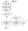
- the microcomputer 11 executes steps 201 to 211 shown in the flowchart of Fig. 6 in an interrupting manner at every predetermined interval (for example, every 200 ⁇ seconds).
- the microcomputer 11 differentiates the rotation angle ⁇ with respect to time, that is, divides the difference between the value in the preceding control and the value of the current control by a predetermined cycle, thereby computing the rotation angular velocity ⁇ of the brushless motor 2 (step 204).
- the microcomputer 11 determines feedback gains that correspond to the rotation angular velocity ⁇ of the brushless motor 2, that is, determines the values of the d-axis proportionality gain Kdp, the d-axis integration gain Kdi, the q-axis proportionality gain Kqp, and the q-axis integration gain Kqi (step 205).
- the microcomputer 11 uses the feedback gains determined at step 205 to perform feedback control computation (proportionality and integration control) based on the deviation of the d-axis current value Id from the d-axis current command value Id* and the deviation of the q-axis current value Iq from the q-axis current command value Iq*, thereby computing the d-axis voltage command value Vd* and the q-axis voltage command value Vq* (step 206).
- feedback control computation proportionality and integration control
- the microcomputer 11 transforms the d-axis voltage command value Vd* and the q-axis voltage command value Vq* computed at step 206 into three phase voltage command values Vu*, Vv*, Vw* (step 207). Based on the phase voltage command values Vu*, Vv*, Vw*, the microcomputer 11 generates DUTY instruction values ⁇ u, ⁇ v, ⁇ w of each of the phases (PWM control computation, step 208).
- the microcomputer 11 determines the values of dead time compensation amounts ⁇ u, ⁇ v, ⁇ w of each of the phases according to the rotation angular velocity ⁇ (step 209). Using the dead time compensation amounts ⁇ u, ⁇ v, ⁇ w, the microcomputer 11 corrects the DUTY instruction values ⁇ u, ⁇ v, ⁇ w at step 210 (dead time compensation computation, see Fig. 5). Based on the DUTY instruction values ⁇ u', ⁇ v', ⁇ w' computed at step 210, the microcomputer 11 generates a gate ON/OFF signal, and sends the gate ON/OFF signal to the PWM inverter 12 (PWM output, step 211).
- the output (renewal) of a gate ON/OFF signal is executed in an interrupting manner at every predetermined interval. Therefore, as the rotational speed of the motor is increased, the number of rotation of the motor per one output (renewal) of the gate ON/OFF signal is increased, that is, the motor control is made rougher. As a result, a shift of a current zero cross point until the gate ON/OFF signal is renewed displaces the time at which the dead time compensation is switched. That is, in some cases, the dead time compensation amount ⁇ x that should be added to the DUTY instruction value ⁇ x is subtracted from the DUTY instruction value ⁇ x. Also, in other cases, dead time compensation amount ⁇ x that should be subtracted from the DUTY instruction value ⁇ x is added to the DUTY instruction value ⁇ x. In either case, current distortion is increased.
- the microcomputer 11 includes the rotation angular velocity computation section 35, which computes the rotation angular velocity ⁇ of the brushless motor 2, the feedback gain determination section 36, which determines the feedback gains (Kdp, Kdi, Kqp, Kqi) based on the rotation angular velocity ⁇ , and the dead time compensation amount determination section 40, which determines the values of the dead time compensation amounts ⁇ u, ⁇ v, ⁇ w.
- the greater the absolute value of the rotation angular velocity ⁇ the smaller the values of the dead time compensation amounts ⁇ u, ⁇ v, ⁇ w determined by the dead time compensation amount determination section 40 become.
- the feedback gains for low speed rotation of the brushless motor 2 are set to a low values, so that sound noise and vibration due to current noise are avoided, while current distortion due to dead time is suppressed by addition or subtraction of the dead time compensation amount ⁇ x. Therefore, regardless of the rotation speed of the brushless motor 2, the current distortion accompanying the setting of the dead time is accurately compensated for.
- This configuration may be changed. For example, when the absolute value of the rotation angular velocity ⁇ is greater than a predetermined value, the dead time compensation amount ⁇ x may be determined to have value less than a value of the case where the absolute value of the rotation angular velocity ⁇ is equal to or less than the predetermined value.
- the dead time compensation with addition or subtraction of the dead time compensation amount ⁇ x does not need to be substantially performed.
- This modification has the same advantages as those of the illustrated embodiment. Particularly, since the value of the dead time compensation amount ⁇ x is determined to zero, inversion of addition and subtraction of the dead time compensation amount ⁇ x with respect to the DUTY instruction value ⁇ x does not generate current distortion.
- the predetermined value is preferably set to a value of the rotation angular velocity ⁇ that can cause inversion of addition and subtraction of the dead time compensation amount ⁇ x.
- the value of the rotation angular velocity ⁇ is obtained through experiments and simulations.
- the feedback gain determination section 36 determines the feedback gains (Kdp, Kdi, Kqp, Kqi), which correspond to the rotation angular velocity ⁇ , based on the gain maps 36a to 36d, and the dead time compensation amount determination section 40 determines the dead time compensation amounts ⁇ u, ⁇ v, ⁇ w based on the compensation amount maps 40a to 40c.
- the feedback gains (Kdp, Kdi, Kqp, Kqi) corresponding to the rotation angular velocity ⁇ and the dead time compensation amounts ⁇ u, ⁇ v, ⁇ w may be determined using a function of the rotation angular velocity w.
- the configurations of the maps are not limited to those of the gain maps 36a to 36d and the compensation amount maps 40a to 40c.
- the maps may be configured such that, as the absolute value of the rotation angular velocity ⁇ increases, the dead time compensation amount is monotonously decreases or the feedback gains monotonously increase.
- the proportionality gain and the integration gain do not necessarily increase together as the absolute value of the rotation angular velocity ⁇ increases. It is sufficient if at least one of the proportionality gain and the integration gain increases. One of the proportionality gain and the integration gain may decrease as long as the responsivity of the feedback control is eventually improved.
- a microcomputer includes a rotation angular velocity computation section, a feedback gain determination section, and a dead time compensation amount determination section.
- the rotation angular velocity determination section computes the rotation angular velocity of a brushless motor. Based on the rotation angular velocity, the feedback gain determination section determines feedback gains.
- the dead time compensation amount determination section determines a dead time compensation amount. The greater the absolute value of the rotation angular velocity, that is, the higher the rotation speed of the brushless motor, the greater the feedback gains determined by the feedback gain determination section become, and the higher the responsivity of the feedback gains becomes. The greater the absolute value of the rotation angular velocity, the smaller the dead time compensation amount determined by the dead time compensation amount determination section becomes.
Abstract
The rotation angular velocity determination section computes the rotation angular velocity of a brushless motor. Based on the rotation angular velocity, the feedback gain determination section determines feedback gains. The dead time compensation amount determination section determines a dead time compensation amount. The greater the absolute value of the rotation angular velocity, that is, the higher the rotation speed of the brushless motor, the greater the feedback gains determined by the feedback gain determination section become, and the higher the responsivity of the feedback gains becomes. The greater the absolute value of the rotation angular velocity, the smaller the dead time compensation amount determined by the dead time compensation amount determination section becomes.
Description
- The present invention relates to a motor controller and an electric power steering apparatus.
- Conventionally, a type of a motor controller has been used which converts direct-current voltage supplied from a direct-current power supply to three-phase (U, V, W) drive power using a PWM (pulse-width modulation) inverter, and supplies the three-phase drive power to a brushless motor.
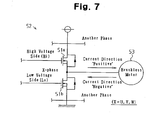
- As shown in Fig. 7, a PWM inventor is configured of three
arms 52 in parallel as basic units. Eacharm 52 corresponds to one of the phases and includes a pair of switching elements (for example, power MOSFETs) 51a, 51b in series. The motor controller alternately turns on and off the high voltageside switching element 51a and the low voltageside switching element 51b of eacharm 52 at a predetermined timing, thereby supplying three-phase drive power to abrushless motor 53. - In such a motor controller, to prevent a short circuit (arm short circuit) between each high voltage
side switching element 51a and the corresponding low voltageside switching element 51b, "dead time" is set when theswitching elements switching elements - In an electric power steering (EPS) apparatus, a motor, which is a driving source, is controlled through a feedback control based on a deviation of an actual current value from a current command value that is a control target of assisting force (assist torque). When the steering wheel is being turned slowly, that is, when the motor rotates slowly, the torque sensor is likely to pick up current noise. Particularly, during extreme steering, which causes a large current to pass through the PWM inverter, current noise is likely to be produced. Thus, rotation of the motor is influenced by current noise. Accordingly, unstable rotation of the motor significantly increases sound noise and vibration. Therefore, a feedback gain for low speed rotation of the motor is generally set to a small value. As a result, when the motor is rotating at a low speed, the influence of current distortion, which accompanies dead time described above, is likely to appear.
- Accordingly, in conventional motor controls including motor controls used in EPS apparatuses, dead time compensation is performed to reduce errors between a voltage command value and an output voltage to suppress the occurrence of current distortion accompanying dead time.
- For example, as shown in Fig. 8, a method has been proposed in which a dead time compensation amount β is added to or subtracted from a DUTY instruction value αx. The DUTY instruction value αx is compared with a triangular wave δ, which is a carrier wave, to determine the time of turning on and off the
switching elements - More specifically, when the direction of a current of X-phase (X = U, V, W, the same applies hereinafter) that corresponds to one of the
arms 52 is toward thebrushless motor 53 from thearm 52, that is, when the direction of current is "positive" (see Fig. 7), the dead time compensation amount β is added to the DUTY instruction value αx. When the direction of current is toward thearm 52 from thebrushless motor 53, that is, when the direction of current is "negative" (see fig. 7), the dead time compensation amount β is subtracted from the DUTY instruction value αx. This equalizes a time in which the X-phase output voltage Vx becomes the power supply voltage Vb (t3 + t4 or t5 + t6) in a cycle T of the triangular wave δ with the corresponding time (t1 + t2) in a case where no dead time is set (ideal voltage waveform). Thus, the voltage command value is caused to match the output voltage of the PWM inventor, so that current distortion due to dead time is prevented. - In recent years, software servo control performed by a microcomputer is most commonly used for controlling motors in steering systems. In software servo control, the output (renewal) of gate ON/OFF signals for performing a motor control that includes the above described dead time compensation, that is, the output (renewal) of gate ON/OFF signals for turning on and off switching elements of a PWM inverter, is performed in an interrupting manner at every predetermined cycle. That is, as the rotational speed of the motor is increased, the number of rotation of the motor per one output (renewal) of the gate ON/OFF signal is increased, that is, the motor control is made rougher.
- Therefore, until the gate ON/OFF signal is renewed, a current zero cross point, which is the time at which the dead time compensation is switched, is displaced. That is, the switching time in the control and the actual switching time are deviated from each other. As a result, the dead time compensation amount β, which should be added to the DUTY instruction value αx, is subtracted from the DUTY instruction value αx in some cases. In other cases, the dead time compensation amount β, which should be subtracted from the DUTY instruction value αx, is added to the DUTY instruction value αx in other cases. In either case, current distortion is increased.
- Accordingly, it is an objective of the present invention to provide a motor controller and an electric power steering apparatus that, irrespective of the rotational speed of the motor, accurately compensate for current distortion due to dead time.
- To achieve the foregoing and other objectives and in accordance with the purpose of the present invention, a motor controller including a DUTY instruction value generation section, a PWM output section, and a PWM inverter is provided. The DUTY instruction value generation section generates a DUTY instruction value through a feedback control based on a deviation of an actual current value from a current command value. The PWM output section outputs a gate ON/OFF signal according to comparison between the DUTY instruction value and a carrier wave. The PWM inverter is formed of a plurality of switching element circuits connected in parallel. Each switching element circuit is formed of a pair of switching elements connected in series. When each switching element is turned on and off based on the gate ON/OFF signal, the PWM inverter converts a direct-current power supply to three-phase drive power, and supplies the three-phase drive power to a brushless motor. Dead time is set to prevent arm short circuits due to ON/OFF switching of each switching element. The gate ON/OFF signal is renewed at every predetermined cycle. The motor controller, further includes a current direction determination section, a rotation angular velocity computation section, a compensation amount determination section, a dead time compensation section, and a gain determination section. The current direction determination section determines the direction of current of each phase. The rotation angular velocity computation section computes a rotation angular velocity of the brushless motor. The compensation amount determination section determines a compensation amount for correcting the DUTY instruction value based on the rotation angular velocity. The greater the absolute value of the rotation angular velocity, the smaller the compensation amount determined by the compensation amount determination section becomes. The dead time compensation section selectively adds the compensation amount to and subtracts the compensation amount from the DUTY instruction value according to the current direction of each phase. The gain determination section determines a feedback gain of the feedback control based on the rotation angular velocity. The gain determination section changes the feedback gain such that the greater the absolute value of the rotation angular velocity, the higher the responsivity of the feedback control becomes.
- The present invention provides another motor controller comprising a DUTY instruction value generation section, a PWM output section, and a PWM inverter. The DUTY instruction value generation section generates a DUTY instruction value through a feedback control based on a deviation of an actual current value from a current command value. The PWM output section outputs a gate ON/OFF signal according to comparison between the DUTY instruction value and a carrier wave. The PWM inverter is formed of a plurality of switching element circuits connected in parallel. Each switching element circuit is formed of a pair of switching elements connected in series. When each switching element is turned on and off based on the gate ON/OFF signal, the PWM inverter converts a direct-current power supply to three-phase drive power, and supplies the three-phase drive power to a brushless motor. Dead time is set to prevent arm short circuits due to ON/OFF switching of each switching element. The gate ON/OFF signal is renewed at every predetermined cycle. The motor controller further includes a current direction determination section, a rotation angular velocity computation section, a compensation amount determination section, a dead time compensation section, and a gain determination section. The current direction determination section determines the direction of current of each phase. The rotation angular velocity computation section computes a rotation angular velocity of the brushless motor. The compensation amount determination section determines a compensation amount for correcting the DUTY instruction value based on the rotation angular velocity. The greater the absolute value of the rotation angular velocity, the smaller the compensation amount determined by the compensation amount determination section become. The dead time compensation section selectively adds the compensation amount to and subtracts the compensation amount from the DUTY instruction value according to the current direction of each phase. The gain determination section determines a feedback gain of the feedback control based on the rotation angular velocity. The greater the absolute value of the rotation angular velocity, the greater the value of the feedback gain determined by the gain determination section becomes.
- Further, the present invention provides a motor controller including a DUTY instruction value generation section, a PWM output section, and a PWM inverter. The DUTY instruction value generation section generates a DUTY instruction value through a feedback control based on a deviation of an actual current value from a current command value. The PWM output section outputs a gate ON/OFF signal according to comparison between the DUTY instruction value and a carrier wave. The PWM inverter is formed of a plurality of switching element circuits connected in parallel. Each switching element circuit is formed of a pair of switching elements connected in series. When each switching element is turned on and off based on the gate ON/OFF signal, the PWM inverter converts a direct-current power supply to three-phase drive power, and supplies the three-phase drive power to a brushless motor. Dead time is set to prevent arm short circuits due to ON/OFF switching of each switching element. The gate ON/OFF signal is renewed at every predetermined cycle. The motor controller further includes a current direction determination section, a rotation angular velocity computation section, a compensation amount determination section, a dead time compensation section, and a gain determination section. The current direction determination section determines the direction of current of each phase. The rotation angular velocity computation section computes a rotation angular velocity of the brushless motor. The compensation amount determination section determines a compensation amount for correcting the DUTY instruction value based on the rotation angular velocity. When the absolute value of the rotation angular velocity is greater than a predetermined value, the compensation amount determination section determines the compensation amount such that the compensation amount is smaller than the compensation amount in a case where the absolute value of the rotational angular velocity is less than the predetermined value. The dead time compensation section selectively adds the compensation amount to and subtracts the compensation amount from the DUTY instruction value according to the current direction of each phase. The gain determination section determines a feedback gain of the feedback control based on the rotation angular velocity. The greater the absolute value of the rotation angular velocity, the greater the value of the feedback gain determined by the gain determination section becomes.
- In another aspect of the present invention, an electric power steering apparatus having a motor controller is provided. The motor controller includes a DUTY instruction value generation section, a PWM output section, a PWM inverter, a current direction determination section, a rotation angular velocity computation section, a compensation amount determination section, a dead time compensation section, and a gain determination section. The DUTY instruction value generation section generates a DUTY instruction value through a feedback control based on a deviation of an actual current value from a current command value. The PWM output section outputs a gate ON/OFF signal according to comparison between the DUTY instruction value and a carrier wave. The PWM inverter is formed of a plurality of switching element circuits connected in parallel. Each switching element circuit is formed of a pair of switching elements connected in series. When each switching element is turned on and off based on the gate ON/OFF signal, the PWM inverter converts a direct-current power supply to three-phase drive power, and supplies the three-phase drive power to a brushless motor. Dead time is set to prevent arm short circuits due to ON/OFF switching of each switching element. The gate ON/OFF signal is renewed at every predetermined cycle. The current direction determination section determines the direction of current of each phase. The rotation angular velocity computation section computes a rotation angular velocity of the brushless motor. The compensation amount determination section determines a compensation amount for correcting the DUTY instruction value based on the rotation angular velocity. The greater the absolute value of the rotation angular velocity, the smaller the compensation amount determined by the compensation amount determination section become. The dead time compensation section selectively adds the compensation amount to and subtracts the compensation amount from the DUTY instruction value according to the current direction of each phase. The gain determination section determines a feedback gain of the feedback control based on the rotation angular velocity. The gain determination section changes the feedback gain such that the greater the absolute value of the rotation angular velocity, the higher the responsivity of the feedback control becomes.
- The present invention provides another electric power steering apparatus having a motor controller. The motor controller includes a DUTY instruction value generation section, a PWM output section, a PWM inverter, a current direction determination section, a rotation angular velocity computation section, a compensation amount determination section, a dead time compensation section, a gain determination section. The DUTY instruction value generation section generates a DUTY instruction value through a feedback control based on a deviation of an actual current value from a current command value. The PWM output section outputs a gate ON/OFF signal according to comparison between the DUTY instruction value and a carrier wave. The PWM inverter is formed of a plurality of switching element circuits connected in parallel. Each switching element circuit is formed of a pair of switching elements connected in series. When each switching element is turned on and off based on the gate ON/OFF signal, the PWM inverter converts a direct-current power supply to three-phase drive power, and supplies the three-phase drive power to a brushless motor. Dead time is set to prevent arm short circuits due to ON/OFF switching of each switching element. The gate ON/OFF signal is renewed at every predetermined cycle. The current direction determination section determines the direction of current of each phase. The rotation angular velocity computation section computes a rotation angular velocity of the brushless motor. The compensation amount determination section determines a compensation amount for correcting the DUTY instruction value based on the rotation angular velocity. The greater the absolute value of the rotation angular velocity, the smaller the compensation amount determined by the compensation amount determination section become. The dead time compensation section selectively adds the compensation amount to and subtracts the compensation amount from the DUTY instruction value according to the current direction of each phase. The gain determination section determines a feedback gain of the feedback control based on the rotation angular velocity. The greater the absolute value of the rotation angular velocity, the greater the value of the feedback gain determined by the gain determination section becomes.
- Further, the present invention provides another an electric power steering apparatus having a motor controller. The motor controller includes a DUTY instruction value generation section, a PWM output section, a PWM inverter, a current direction determination section, a rotation angular velocity computation section, a compensation amount determination section, a dead time compensation section, and a gain determination section. The DUTY instruction value generation section generates a DUTY instruction value through a feedback control based on a deviation of an actual current value from a current command value. The PWM output section outputs a gate ON/OFF signal according to comparison between the DUTY instruction value and a carrier wave. The PWM inverter is formed of a plurality of switching element circuits connected in parallel. Each switching element circuit is formed of a pair of switching elements connected in series. When each switching element is turned on and off based on the gate ON/OFF signal, the PWM inverter converts a direct-current power supply to three-phase drive power, and supplies the three-phase drive power to a brushless motor. Dead time is set to prevent arm short circuits due to ON/OFF switching of each switching element. The gate ON/OFF signal is renewed at every predetermined cycle. The current direction determination section determines the direction of current of each phase. The rotation angular velocity computation section computes a rotation angular velocity of the brushless motor. The compensation amount determination section determines a compensation amount for correcting the DUTY instruction value based on the rotation angular velocity. When the absolute value of the rotation angular velocity is greater than a predetermined value, the compensation amount determination section determines the compensation amount such that the compensation amount is smaller than the compensation amount in a case where the absolute value of the rotational angular velocity is less than the predetermined value. The dead time compensation section that selectively adds the compensation amount to and subtracts the compensation amount from the DUTY instruction value according to the current direction of each phase. The gain determination section determines a feedback gain of the feedback control based on the rotation angular velocity. The greater the absolute value of the rotation angular velocity, the greater the value of the feedback gain determined by the gain determination section becomes.
- Other aspects and advantages of the invention will become apparent from the following description, taken in conjunction with the accompanying drawings, illustrating by way of example the principles of the invention.
- The invention, together with objects and advantages thereof, may best be understood by reference to the following description of the presently preferred embodiments together with the accompanying drawings in which:
- Fig. 1 is a view illustrating an EPS apparatus according to a preferred embodiment of the present invention;
- Fig. 2 is a block diagram showing the configuration of the ECU;
- Figs. 3A to 3D are diagrams showing gain maps;
- Figs. 4A to 4C are diagrams showing compensation amount maps;
- Fig. 5 is a flowchart showing a procedure of a dead time compensation computation;
- Fig. 6 is a flowchart showing a procedure of a motor control;
- Fig. 7 is a diagram showing an arm forming a prior art PWM inverter; and
- Fig. 8 is a waveform chart for explaining the operation of prior art compensation.
- Hereinafter, an electric power steering (EPS) apparatus according to a preferred embodiment of the present invention will be described with reference to the drawings.
- As shown in Fig. 1, the
EPS apparatus 1 includes abrushless motor 2 and anECU 3. Thebrushless motor 2 functions as a driving source that applies assisting force to the steering system of a vehicle. TheECU 3 functions as a motor controller that controls thebrushless motor 2. - A
steering wheel 4 is coupled to arack 6 with asteering shaft 5. Rotation of thesteering shaft 5 caused by steering operation is converted into linear reciprocation of therack 6 by means of a rack-and-pinion mechanism (not shown) and is transmitted to steeredwheels 8. TheEPS apparatus 1 according to this embodiment is a rack type EPS apparatus, in which thebrushless motor 2 is arranged coaxial with therack 6. Assist torque generated by thebrushless motor 2 is transmitted to therack 6 through a ball screw mechanism (not shown). TheECU 3 controls assisting force applied to the steering system by controlling the assist torque generated by themotor 2. - As shown in Fig. 2, the
ECU 3 includes amicrocomputer 11 and aPWM inverter 12. Themicrocomputer 11 outputs gate ON/OFF signals. ThePWM inverter 12 supplies three-phase (U, V, W) drive power to thebrushless motor 2 based on the gate ON/OFF signals. - The
ECU 3 according to this embodiment is connected to a torque sensor 14 for detecting steering torque τ and a vehicle speed sensor 15 (see Fig. 1) for detecting a vehicle speed V. Based on the inputted steering torque τ and the vehicle speed V, themicrocomputer 11 determines assisting force to be applied to the steering system, that is, assist torque to be generated by themotor 2. Themicrocomputer 11 is also connected to twocurrent sensors 17, 18, and arotation angle sensor 19. Thecurrent sensors 17, 18 detect values of current supplied to thebrushless motor 2. Therotation angle sensor 19 detects the rotation angle (electrical angle) θ of thebrushless motor 2. Based on the output signals of these sensors, themicrocomputer 11 detects phase current values Iu, Iv, Iw, and the rotation angle θ of thebrushless motor 2. Based on the detected phase current values Iu, Iv, Iw and the rotation angle θ, themicrocomputer 11 outputs a gate ON/OFF signal for causing themotor 2 to generate the determined assist torque. - On the other hand, the
PWM inverter 12 is formed of a plurality (in this embodiment, 2 x 3) of power MOSFETs (hereinafter, simply referred to as FETs), each of which corresponds to one of the phases of thebrushless motor 2. More specifically, thePWM inverter 12 is formed by connecting threearms arm 22u is a series circuit ofFETs node 23u of theFETs brushless motor 2. Thearm 22v is a series circuit of FETs 21b, 21e, and a node 23v of the FETs 21b, 21e is connected to a V phase coil of thebrushless motor 2. Thearm 22w is a series circuit of FETs 21c, 21f, and anode 23w of the FETs 21c, 21f is connected to a W phase coil of thebrushless motor 2. - The gate ON/OFF signals outputted by the
microcomputer 11 are applied to the gate terminals of the FETs 21a to 21f. In response to the gate ON/OFF signals, theFETs 21a to 21f are turned on and off. This converts direct current voltage from the direct-current power supply 25 into drive power of each phase, which is in turn supplied to thebrushless motor 2. - Operations of the motor control and the dead time compensation of the present embodiment will now be described.
- In this embodiment, the
microcomputer 11 maps the phase current values Iu, Iv, Iw to a d/q coordinate system (d/q transformation), thereby performing a current feedback control on the d/q coordinate system. Further, themicrocomputer 11 generates DUTY instruction values that determine the time of turning on and off of the FETs 21a to 21f forming thePWM inverter 12, and outputs the gate ON/OFF signals based on the DUTY instruction values. - Specifically, the steering torque τ detected by the torque sensor 14 and the vehicle speed V detected by the
vehicle speed sensor 15 are sent to a current command value computation section 31. Based on the inputted steering torque τ and vehicle speed V, the current command value computation section 31 computes a q-axis current command value Iq*, which is a control target of the assist torque. The phase current values Iu, Iv, Iw detected by thecurrent sensors 17, 18, and the rotation angle θ detected by therotation angle sensor 19 are sent to a d/qtransformation computation section 32. Based on the inputted rotation angle θ, the d/qtransformation computation section 32 transforms the phase current values Iu, Iv, Iw into a d-axis current value Id and a q-axis current value Iq on the d/q coordinate system. - The q-axis current command value Iq* computed by the current command value computation section 31, and the d-axis current value Id and the q-axis current value Iq computed by the d/q
transformation computation section 32 are sent to PIcontrol computation sections control computation section 33, which corresponds to the d-axis, receives zero as a d-axis current command value Id* (Id* = 0). The PIcontrol computation section 33 performs feedback control (proportionality and integration control) based on the deviation of the d-axis current value Id from the d-axis current command value Id*, thereby computing a d-axis voltage command value Vd*. Likewise, the PIcontrol computation section 34, which corresponds to the q-axis, computes a q-axis voltage command value Vq* based on the deviation of the q-axis current value Iq from the q-axis current command value Iq*. - The
microcomputer 11 according to this embodiment includes a rotation angularvelocity computation section 35 and a feedbackgain determination section 36. The rotation angularvelocity computation section 35 functions as a rotation angular velocity computation section that computes the rotation angular velocity ω of thebrushless motor 2 based on the rotation angle θ. The feedbackgain determination section 36 functions as a gain determination section that determines a feedback gain used in the feedback control based on the rotation angular velocity ω. - The feedback
gain determination section 36 according to this embodiment determines, as the feedback gains, a d-axis proportionality gain Kdp and a d-axis integration gain Kdi, and a q-axis proportionality gain Kqp and a q-axis integration gain Kqi. More specifically, the feedbackgain determination section 36 hasgain maps 36a to 36d, in which the absolute value of the rotation angular velocity ω is related to the feedback gains Kdp, Kdi, Kqp, Kqi (see Figs. 3A to 3D). In each of the gain maps 36a to 36d, the feedback gain increases as the absolute value of the rotation angular velocity ω increases. Based on the gain maps 36a to 36d, the feedbackgain determination section 36 determines feedback gains that correspond to the rotation angular velocity ω, that is, determines the values of the d-axis proportionality gain Kdp, the d-axis integration gain Kdi, the q-axis proportionality gain Kqp and the q-axis integration gain Kqi. - In this embodiment, the greater the absolute value of the rotation angular velocity ω, that is, the higher the rotation speed of the
brushless motor 2, the greater the feedback gains determined by the feedbackgain determination section 36 become, and the higher the responsivity of the feedback gains becomes. The PIcontrol computation sections gain determination section 36. - The d-axis voltage command value Vd* and the q-axis voltage command value Vq* computed by the PI
control computation sections transformation computation section 37 together with the rotation angle θ. Based on the inputted rotation angle θ, the d/q inversetransformation computation section 37 transforms the d-axis voltage command value Vd* and the q-axis voltage command value Vq* to three phase voltage command values Vu*, Vv*, Vw*, and sends the voltage command value Vu*, Vv*, Vw* to aPWM computation section 38. Based on the phase voltage command values Vu*, Vv*, Vw*, thePWM computation section 38 generates DUTY instruction values αu, αv, αw of each of the phases. That is, in this embodiment, the d/qtransformation computation section 32, the PIcontrol computation sections transformation computation section 37, and thePWM computation section 38 form a DUTY instruction value generation section. - The
microcomputer 11 according to this embodiment includes a dead timecompensation computation section 39 and a dead time compensationamount determination section 40 for correcting the DUTY instruction values αu, αv, αw of each of the phases to compensate for current distortion due to dead time. The dead timecompensation computation section 39 functions as a determination section and a dead time compensation section. The dead time compensationamount determination section 40 functions as a compensation amount determination section that determines the compensation amount of dead time. The DUTY instruction values αu', αv', αw' corrected by the dead timecompensation computation section 39 are sent to a PWM output section 41. - Specifically, the dead time compensation
amount determination section 40 hascompensation amount maps 40a to 40c, in which dead time compensation amounts βu, βv, βw of each of the phases are related to the absolute value of the rotation angular velocity ω (see Figs. 4(a) to 4(c)). In each of thecompensation amount maps 40a to 40c, each of the dead time compensation amounts βu, βv, βw decreases as the absolute value of the rotation angular velocity ω increases. Based on thecompensation amount maps 40a to 40c, the dead time compensationamount determination section 40 determines the values of the dead time compensation amount βu, βv, βw that correspond to the rotation angular velocity ω. - In this embodiment, the greater the absolute value of the rotation angular velocity ω, that is, the higher the rotation speed of the
brushless motor 2, the smaller the dead time compensation amount βu, βv, βw determined by the dead time compensationamount determination section 40 become. The dead timecompensation computation section 39 corrects the DUTY instruction values αu, αv, αw of each of the phases based on the dead time compensation amounts βu, βv, βw determined by the dead time compensationamount determination section 40. - Together with the DUTY instruction value αx for each phase and the dead time compensation amount βx, the dead time
compensation computation section 39 receives phase current value Ix. The dead timecompensation computation section 39 determines the direction of current of each phase based on the phase current values Ix. According to the direction of current of each phase, the dead timecompensation computation section 39 adds or subtracts the dead time compensation amount βx to or from the DUTY instruction value αx, thereby correcting the DUTY instruction value αx. - That is, as shown in the flowchart of Fig. 5, when receiving the DUTY instruction value αx of the X phase (step 101), the dead time compensation amount βx (step 102), and the phase current value Ix of the X phase (step 103), the dead time
compensation computation section 39 first determines whether the direction of current of the X phase is positive (step 104). When determining that the current direction of the X phase is positive (Ix > 0, step 104: YES), themicrocomputer 11 adds the dead time compensation amount βx received atstep 102 to the X-phase DUTY instruction value αx, thereby correcting the DUTY instruction value αx, and sends the corrected DUTY instruction value αx' to the PWM output section 41 (αx' = αx + βx, step 105). - On the other hand, when determining that the current direction of the X phase is not positive at step 104 (step 104: NO), the
microcomputer 11 determines whether the current direction of the X phase is negative (step 106). When determining that the current direction of the X phase is negative (Ix < 0, step 106: YES), themicrocomputer 11 subtracts the dead time compensation amount βx received atstep 102 from the X-phase DUTY instruction value αx, thereby correcting the DUTY instruction value αx, and sends the corrected DUTY instruction value αx' to the PWM output section 41 (αx' = αx - βx, step 107). - At
step 106, when determining that the current direction of the X phase is not negative (step 106: NO), that is, when the phase current value of the X phase is 0, the dead timecompensation computation section 39 does not correct the DUTY instruction value αx received at step 101 (αx' = αx, step 108). - In this manner, the dead time
compensation computation section 39 executessteps 101 to 108 for each phase, thereby correcting the DUTY instruction values αu, αv, αw of the U, V, and W phases, and sends the corrected DUTY instruction values αu', αv', αw' to the PWM output section 41. Then, based on the comparison between the DUTY instruction values αu', αv', αw' corrected by the dead timecompensation computation section 39 and the triangular wave δ, which is a carrier wave, the PWM output section 41 generates the gate ON/OFF signal (see Fig. 8), and sends the gate ON/OFF signal to thePWM inverter 12. - The procedure of the motor control performed by the
microcomputer 11 according to this embodiment will now be described. - The
microcomputer 11 according to this embodiment executessteps 201 to 211 shown in the flowchart of Fig. 6 in an interrupting manner at every predetermined interval (for example, every 200µ seconds). - That is, the
microcomputer 11 first detects state quantities (the phase current values Iu, Iv, Iw, the rotation angle θ, the steering torque τ, and the vehicle speed V) atstep 201 based on output signals of the sensors. Subsequently, themicrocomputer 11 computes the q-axis current command value Iq*, which is a control target of the assist torque generated by thebrushless motor 2, and the d-axis current command value Id*(Id* = 0) atstep 202. Through the d/q transformation, themicrocomputer 11 transforms the phase current values Iu, Iv, Iw detected atstep 201 into the d-axis current value Id and the q-axis current value Iq (step 203). - Next, the
microcomputer 11 differentiates the rotation angle θ with respect to time, that is, divides the difference between the value in the preceding control and the value of the current control by a predetermined cycle, thereby computing the rotation angular velocity ω of the brushless motor 2 (step 204). Themicrocomputer 11 then determines feedback gains that correspond to the rotation angular velocity ω of thebrushless motor 2, that is, determines the values of the d-axis proportionality gain Kdp, the d-axis integration gain Kdi, the q-axis proportionality gain Kqp, and the q-axis integration gain Kqi (step 205). Using the feedback gains determined atstep 205, themicrocomputer 11 performs feedback control computation (proportionality and integration control) based on the deviation of the d-axis current value Id from the d-axis current command value Id* and the deviation of the q-axis current value Iq from the q-axis current command value Iq*, thereby computing the d-axis voltage command value Vd* and the q-axis voltage command value Vq* (step 206). - Subsequently, through the d/q inverse transformation, the
microcomputer 11 transforms the d-axis voltage command value Vd* and the q-axis voltage command value Vq* computed atstep 206 into three phase voltage command values Vu*, Vv*, Vw* (step 207). Based on the phase voltage command values Vu*, Vv*, Vw*, themicrocomputer 11 generates DUTY instruction values αu, αv, αw of each of the phases (PWM control computation, step 208). - Based on the rotation angular velocity ω computed at
step 204, themicrocomputer 11 determines the values of dead time compensation amounts βu, βv, βw of each of the phases according to the rotation angular velocity ω (step 209). Using the dead time compensation amounts βu, βv, βw, themicrocomputer 11 corrects the DUTY instruction values αu, αv, αw at step 210 (dead time compensation computation, see Fig. 5). Based on the DUTY instruction values αu', αv', αw' computed atstep 210, themicrocomputer 11 generates a gate ON/OFF signal, and sends the gate ON/OFF signal to the PWM inverter 12 (PWM output, step 211). - According to this embodiment, the following advantages are obtained.
- In a software servo control performed by a microcomputer, the output (renewal) of a gate ON/OFF signal is executed in an interrupting manner at every predetermined interval. Therefore, as the rotational speed of the motor is increased, the number of rotation of the motor per one output (renewal) of the gate ON/OFF signal is increased, that is, the motor control is made rougher. As a result, a shift of a current zero cross point until the gate ON/OFF signal is renewed displaces the time at which the dead time compensation is switched. That is, in some cases, the dead time compensation amount βx that should be added to the DUTY instruction value αx is subtracted from the DUTY instruction value αx. Also, in other cases, dead time compensation amount βx that should be subtracted from the DUTY instruction value αx is added to the DUTY instruction value αx. In either case, current distortion is increased.
- In this respect, the
microcomputer 11 according to this embodiment includes the rotation angularvelocity computation section 35, which computes the rotation angular velocity ω of thebrushless motor 2, the feedbackgain determination section 36, which determines the feedback gains (Kdp, Kdi, Kqp, Kqi) based on the rotation angular velocity ω, and the dead time compensationamount determination section 40, which determines the values of the dead time compensation amounts βu, βv, βw. The greater the absolute value of the rotation angular velocity ω, that is, the higher the rotation speed of thebrushless motor 2, the greater the feedback gains determined by the feedbackgain determination section 36 become, and the higher the responsivity of the feedback gains becomes. The greater the absolute value of the rotation angular velocity ω, the smaller the values of the dead time compensation amounts βu, βv, βw determined by the dead time compensationamount determination section 40 become. - According to this configuration, when the absolute value of the rotation angular velocity ω of the
brushless motor 2 is relatively great, that is, when thebrushless motor 2 is rotating at a relatively high speed, making the motor control rougher, the value of the dead time compensation amount βx, which is added to or subtracted from the DUTY instruction value αx, is decreased. Thus, even if the time at which the dead time compensation is switched is displaced, the influence of inversion of addition or subtraction of the dead time compensation amount βx on the switching time of the dead time compensation is reduced. Current distortion due to the reduction of the dead time compensation amount βx is suppressed by an increase of the feedback gains, that is, by the improvement of the responsivity of the feedback control. As in the prior art, the feedback gains for low speed rotation of thebrushless motor 2 are set to a low values, so that sound noise and vibration due to current noise are avoided, while current distortion due to dead time is suppressed by addition or subtraction of the dead time compensation amount βx. Therefore, regardless of the rotation speed of thebrushless motor 2, the current distortion accompanying the setting of the dead time is accurately compensated for. - The above embodiment may be modified as follows.
- In the illustrated embodiment, the greater the absolute value of the rotation angular velocity ω, the smaller the values of the dead time compensation amount βx determined by the dead time compensation
amount determination section 40 become. This configuration may be changed. For example, when the absolute value of the rotation angular velocity ω is greater than a predetermined value, the dead time compensation amount βx may be determined to have value less than a value of the case where the absolute value of the rotation angular velocity ω is equal to or less than the predetermined value. In this case, when the value of the dead time compensation amount βx of a case where the absolute value of the rotation angular velocity ω is greater than the predetermined value is zero, that is, when the rotation angular velocity w is greater than the predetermined value, the dead time compensation with addition or subtraction of the dead time compensation amount βx does not need to be substantially performed. This modification has the same advantages as those of the illustrated embodiment. Particularly, since the value of the dead time compensation amount βx is determined to zero, inversion of addition and subtraction of the dead time compensation amount βx with respect to the DUTY instruction value αx does not generate current distortion. In this case, the predetermined value is preferably set to a value of the rotation angular velocity ω that can cause inversion of addition and subtraction of the dead time compensation amount βx. The value of the rotation angular velocity ω is obtained through experiments and simulations. - The feedback
gain determination section 36 according to the illustrated embodiment determines the feedback gains (Kdp, Kdi, Kqp, Kqi), which correspond to the rotation angular velocity ω, based on the gain maps 36a to 36d, and the dead time compensationamount determination section 40 determines the dead time compensation amounts βu, βv, βw based on thecompensation amount maps 40a to 40c. However, the feedback gains (Kdp, Kdi, Kqp, Kqi) corresponding to the rotation angular velocity ω and the dead time compensation amounts βu, βv, βw may be determined using a function of the rotation angular velocity w. Further, in the case where the feedback gains (Kdp, Kdi, Kqp, Kqi) and the dead time compensation amounts βu, βv, βw are determined through map computations, the configurations of the maps are not limited to those of the gain maps 36a to 36d and thecompensation amount maps 40a to 40c. The maps may be configured such that, as the absolute value of the rotation angular velocity ω increases, the dead time compensation amount is monotonously decreases or the feedback gains monotonously increase. - Further, the proportionality gain and the integration gain do not necessarily increase together as the absolute value of the rotation angular velocity ω increases. It is sufficient if at least one of the proportionality gain and the integration gain increases. One of the proportionality gain and the integration gain may decrease as long as the responsivity of the feedback control is eventually improved.
- Therefore, the present examples and embodiments are to be considered as illustrative and not restrictive and the invention is not to be limited to the details given herein, but may be modified within the scope and equivalence of the appended claims.
- A microcomputer includes a rotation angular velocity computation section, a feedback gain determination section, and a dead time compensation amount determination section. The rotation angular velocity determination section computes the rotation angular velocity of a brushless motor. Based on the rotation angular velocity, the feedback gain determination section determines feedback gains. The dead time compensation amount determination section determines a dead time compensation amount. The greater the absolute value of the rotation angular velocity, that is, the higher the rotation speed of the brushless motor, the greater the feedback gains determined by the feedback gain determination section become, and the higher the responsivity of the feedback gains becomes. The greater the absolute value of the rotation angular velocity, the smaller the dead time compensation amount determined by the dead time compensation amount determination section becomes.
Claims (6)
- A motor controller comprising a DUTY instruction value generation section, a PWM output section, and a PWM inverter, the DUTY instruction value generation section generating a DUTY instruction value through a feedback control based on a deviation of an actual current value from a current command value, the PWM output section outputting a gate ON/OFF signal according to comparison between the DUTY instruction value and a carrier wave, the PWM inverter being formed of a plurality of switching element circuits connected in parallel, each switching element circuit being formed of a pair of switching elements connected in series, wherein, when each switching element is turned on and off based on the gate ON/OFF signal, the PWM inverter converts a direct-current power supply to three-phase drive power, and supplies the three-phase drive power to a brushless motor, wherein dead time is set to prevent arm short circuits due to ON/OFF switching of each switching element, and wherein the gate ON/OFF signal is renewed at every predetermined cycle, the motor controller being characterized by:a current direction determination section that determines the direction of current of each phase;a rotation angular velocity computation section that computes a rotation angular velocity of the brushless motor;a compensation amount determination section that determines a compensation amount for correcting the DUTY instruction value based on the rotation angular velocity,
wherein the greater the absolute value of the rotation angular velocity, the smaller the compensation amount determined by the compensation amount determination section becomes,a dead time compensation section that selectively adds the compensation amount to and subtracts the compensation amount from the DUTY instruction value according to the current direction of each phase; anda gain determination section that determines a feedback gain of the feedback control based on the rotation angular velocity, wherein the gain determination section changes the feedback gain such that the greater the absolute value of the rotation angular velocity, the higher the responsivity of the feedback control becomes. - A motor controller comprising a DUTY instruction value generation section, a PWM output section, and a PWM inverter, the DUTY instruction value generation section generating a DUTY instruction value through a feedback control based on a deviation of an actual current value from a current command value, the PWM output section outputting a gate ON/OFF signal according to comparison between the DUTY instruction value and a carrier wave, the PWM inverter being formed of a plurality of switching element circuits connected in parallel, each switching element circuit being formed of a pair of switching elements connected in series, wherein, when each switching element is turned on and off based on the gate ON/OFF signal, the PWM inverter converts a direct-current power supply to three-phase drive power, and supplies the three-phase drive power to a brushless motor, wherein dead time is set to prevent arm short circuits due to ON/OFF switching of each switching element, and wherein the gate ON/OFF signal is renewed at every predetermined cycle, the motor controller being characterized by:a current direction determination section that determines the direction of current of each phase;a rotation angular velocity computation section that computes a rotation angular velocity of the brushless motor;a compensation amount determination section that determines a compensation amount for correcting the DUTY instruction value based on the rotation angular velocity,
wherein the greater the absolute value of the rotation angular velocity, the smaller the compensation amount determined by the compensation amount determination section become;a dead time compensation section that selectively adds the compensation amount to and subtracts the compensation amount from the DUTY instruction value according to the current direction of each phase; anda gain determination section that determines a feedback gain of the feedback control based on the rotation angular velocity, wherein the greater the absolute value of the rotation angular velocity, the greater the value of the feedback gain determined by the gain determination section becomes. - A motor controller comprising a DUTY instruction value generation section, a PWM output section, and a PWM inverter, the DUTY instruction value generation section generating a DUTY instruction value through a feedback control based on a deviation of an actual current value from a current command value, the PWM output section outputting a gate ON/OFF signal according to comparison between the DUTY instruction value and a carrier wave, the PWM inverter being formed of a plurality of switching element circuits connected in parallel, each switching element circuit being formed of a pair of switching elements connected in series, wherein, when each switching element is turned on and off based on the gate ON/OFF signal, the PWM inverter converts a direct-current power supply to three-phase drive power, and supplies the three-phase drive power to a brushless motor, wherein dead time is set to prevent arm short circuits due to ON/OFF switching of each switching element, and wherein the gate ON/OFF signal is renewed at every predetermined cycle, the motor controller being characterized by:a current direction determination section that determines the direction of current of each phase;a rotation angular velocity computation section that computes a rotation angular velocity of the brushless motor;a compensation amount determination section that determines a compensation amount for correcting the DUTY instruction value based on the rotation angular velocity,
wherein, when the absolute value of the rotation angular velocity is greater than a predetermined value, the compensation amount determination section determines the compensation amount such that the compensation amount is smaller than the compensation amount in a case where the absolute value of the rotational angular velocity is less than the predetermined value;a dead time compensation section that selectively adds the compensation amount to and subtracts the compensation amount from the DUTY instruction value according to the current direction of each phase; anda gain determination section that determines a feedback gain of the feedback control based on the rotation angular velocity, wherein the greater the absolute value of the rotation angular velocity, the greater the value of the feedback gain determined by the gain determination section becomes. - The motor controller according to claim 3, characterized in that the compensation amount determination section determines the compensation amount such that the compensation amount is zero when the absolute value of the rotational angular velocity is greater than the predetermined value.
- The motor controller according to any one of claims 1 to 4, characterized in that the DUTY instruction value generation section includes a d/q transformation section, a feedback control section, a d/q inverse transformation section, and a PWM computation section,
wherein the d/q transformation section transforms three phase current values into a d-axis current value and a q-axis current value of a d/q coordinate system,
wherein the feedback control section performs a feedback control based on deviation of the d-axis current value and the q-axis current value from a d-axis current command value and a q-axis current command value, thereby computing a d-axis voltage command value and a q-axis voltage command value,
wherein the d/q inverse transformation section transforms the d-axis voltage command value and the q-axis voltage command value into three phase voltage command values,
wherein the PWM computation section computes a DUTY instruction value based on the phase voltage command values, and
wherein the gain determination section determines, as feedback gains, a proportionality gain and an integration gain each corresponding to one of the d-axis and the q-axis. - An electric power steering apparatus being
characterized by:the motor controller according to any one of claims 1 to 5.
Applications Claiming Priority (1)
| Application Number | Priority Date | Filing Date | Title |
|---|---|---|---|
| JP2004260611A JP4581574B2 (en) | 2004-09-08 | 2004-09-08 | Motor control device and electric power steering device |
Publications (3)
| Publication Number | Publication Date |
|---|---|
| EP1634797A2 true EP1634797A2 (en) | 2006-03-15 |
| EP1634797A3 EP1634797A3 (en) | 2006-06-07 |
| EP1634797B1 EP1634797B1 (en) | 2007-08-15 |
Family
ID=35365741
Family Applications (1)
| Application Number | Title | Priority Date | Filing Date |
|---|---|---|---|
| EP05019492A Expired - Fee Related EP1634797B1 (en) | 2004-09-08 | 2005-09-07 | Motor controller and electric power steering apparatus |
Country Status (4)
| Country | Link |
|---|---|
| US (1) | US7126304B2 (en) |
| EP (1) | EP1634797B1 (en) |
| JP (1) | JP4581574B2 (en) |
| DE (1) | DE602005001996T2 (en) |
Cited By (2)
| Publication number | Priority date | Publication date | Assignee | Title |
|---|---|---|---|---|
| WO2009137573A1 (en) * | 2008-05-07 | 2009-11-12 | Microchip Technology Incorporated | Pulse width modulation dead time compensation method and apparatus |
| EP1944861A3 (en) * | 2007-01-09 | 2017-03-01 | JTEKT Corporation | Motor controller and electric power steering system |
Families Citing this family (18)
| Publication number | Priority date | Publication date | Assignee | Title |
|---|---|---|---|---|
| JP4581574B2 (en) * | 2004-09-08 | 2010-11-17 | 株式会社ジェイテクト | Motor control device and electric power steering device |
| JP2006180593A (en) * | 2004-12-21 | 2006-07-06 | Jtekt Corp | Controller for brushless motor |
| JP4749874B2 (en) * | 2006-01-30 | 2011-08-17 | 日立オートモティブシステムズ株式会社 | Power conversion device and motor drive device using the same |
| DE602007013829D1 (en) * | 2006-02-08 | 2011-05-26 | Jtekt Corp | motor control |
| FR2903538B1 (en) * | 2006-07-07 | 2008-09-26 | Schneider Toshiba Inverter Eur Sas | METHOD AND DEVICE FOR ESTIMATING THE SPEED OF AN ELECTRIC MOTOR |
| TWI314811B (en) * | 2006-08-25 | 2009-09-11 | Cheng Uei Prec Ind Co Ltd | Direct current motor controlling method |
| US7659679B2 (en) * | 2007-01-12 | 2010-02-09 | Gm Global Technology Operations, Inc. | System and method for adjusting a dead-time interval in a motor control circuit |
| JP4967766B2 (en) * | 2007-04-06 | 2012-07-04 | 日本精工株式会社 | Electric power steering control device |
| TWI382666B (en) * | 2009-06-04 | 2013-01-11 | Princeton Technology Corp | Dead-time detecting circuit for inductive load and the modulation circuit using the same |
| JP5321614B2 (en) * | 2011-02-28 | 2013-10-23 | 株式会社デンソー | Rotating machine control device |
| JP6361178B2 (en) * | 2014-03-07 | 2018-07-25 | 株式会社ジェイテクト | Motor control device and electric power steering device |
| JP5850116B1 (en) * | 2014-09-26 | 2016-02-03 | ダイキン工業株式会社 | Power converter |
| JP6243385B2 (en) | 2015-10-19 | 2017-12-06 | ファナック株式会社 | Machine learning apparatus and method for learning correction value in motor current control, correction value calculating apparatus and motor driving apparatus provided with the machine learning apparatus |
| JP6168211B2 (en) * | 2015-12-28 | 2017-07-26 | ダイキン工業株式会社 | Power converter |
| EP3476695B1 (en) * | 2016-08-24 | 2020-11-18 | NSK Ltd. | Electric power steering device |
| JP6711255B2 (en) | 2016-12-08 | 2020-06-17 | 株式会社デンソー | MOTOR CONTROL DEVICE AND ELECTRIC POWER STEERING DEVICE USING THE SAME |
| JP7204409B2 (en) * | 2018-10-11 | 2023-01-16 | ローム株式会社 | motor driver device |
| CN112650049B (en) * | 2019-10-11 | 2023-01-20 | 博世华域转向系统有限公司 | System and method for signal acquisition and control output of electric power steering motor |
Family Cites Families (69)
| Publication number | Priority date | Publication date | Assignee | Title |
|---|---|---|---|---|
| JPS58130792A (en) * | 1982-01-28 | 1983-08-04 | Fanuc Ltd | Drive device for synchronous motor |
| JPS5972991A (en) * | 1982-10-19 | 1984-04-25 | Fanuc Ltd | Controller for motor |
| JPS62107691A (en) * | 1985-10-31 | 1987-05-19 | Mitsubishi Electric Corp | Speed controller for ac motor |
| JPH078146B2 (en) * | 1989-05-23 | 1995-01-30 | 春日電機株式会社 | Inverter control device |
| JPH04121091A (en) * | 1990-09-07 | 1992-04-22 | Fanuc Ltd | Driving system for induction motor |
| JP3185257B2 (en) * | 1991-07-23 | 2001-07-09 | 株式会社明電舎 | Power conversion unit parallel operation device |
| CA2101796C (en) * | 1992-07-21 | 1996-10-01 | Tetsuo Yamada | Vector control apparatus for induction motor |
| JPH05199796A (en) * | 1992-01-17 | 1993-08-06 | Meidensha Corp | Current control system for adjustable speed driving device |
| EP0588213B1 (en) * | 1992-09-16 | 1996-12-18 | Hitachi, Ltd. | Method for measuring characteristic constants of alternating current motor and controller thereof based on said method |
| US5450306A (en) * | 1992-12-07 | 1995-09-12 | Square D Company | Closed loop pulse width modulator inverter with volt-seconds feedback control |
| DE69317642T2 (en) * | 1993-01-11 | 1998-07-09 | Meidensha Electric Mfg Co Ltd | Vector control system for induction motor |
| US5550450A (en) * | 1993-04-28 | 1996-08-27 | Otis Elevator Company | Dead-time effect compensation for pulse-width modulated inverters and converters |
| US5594670A (en) * | 1993-09-03 | 1997-01-14 | Kabushiki Kaisha Meidensha | Apparatus for measuring circuit constant of induction motor with vector control system and method therefor |
| JP2833463B2 (en) * | 1994-02-10 | 1998-12-09 | 株式会社デンソー | AC motor rotation torque detector |
| KR0130537B1 (en) * | 1994-05-31 | 1998-04-09 | 이대원 | Brushless dc motor control system |
| JP2933846B2 (en) * | 1995-03-17 | 1999-08-16 | 東洋電機製造株式会社 | PWM inverter with dead time correction function |
| CA2218738C (en) * | 1995-04-21 | 2008-10-07 | Gec Alsthom Acec Transport S.A. | Method for processing pwm waves and devices therefor |
| JP3430769B2 (en) * | 1996-01-31 | 2003-07-28 | 松下電器産業株式会社 | Current command type PWM inverter |
| KR0179872B1 (en) * | 1996-03-26 | 1999-05-15 | 이종수 | A dead time compensating method of an inverter for a motor drive |
| JPH09331682A (en) * | 1996-06-12 | 1997-12-22 | Meidensha Corp | Power converter |
| US5671130A (en) * | 1996-08-23 | 1997-09-23 | Allen-Bradley Company, Inc. | Method and apparatus for controlling voltage reflections using a motor controller |
| JP3372436B2 (en) * | 1996-11-28 | 2003-02-04 | オークマ株式会社 | Inverter control device |
| US5764024A (en) * | 1997-04-07 | 1998-06-09 | Motorola, Inc. | Pulse width modulator (PWM) system with low cost dead time distortion correction |
| US5850132A (en) * | 1997-07-02 | 1998-12-15 | Allin-Bradley Company, Llc | Apparatus used with AC motors for compensating for turn on delay errors |
| JPH1141078A (en) * | 1997-07-16 | 1999-02-12 | Wako Giken:Kk | Method and device for shortening dead time of semiconductor device and pwm inverter |
| JP3678891B2 (en) * | 1997-08-07 | 2005-08-03 | 松下電器産業株式会社 | Output circuit for PWM inverter |
| US5811949A (en) * | 1997-09-25 | 1998-09-22 | Allen Bradley Company, Llc | Turn-on delay compensator for motor control |
| US5917721A (en) * | 1997-11-21 | 1999-06-29 | Allen-Bradley Company, Llc | Apparatus for reducing the effects of turn on delay errors in motor control |
| US6023417A (en) * | 1998-02-20 | 2000-02-08 | Allen-Bradley Company, Llc | Generalized discontinuous pulse width modulator |
| US5977741A (en) * | 1998-11-17 | 1999-11-02 | Allen-Bradley Company, Llc | Method for stabilizing AC induction motor having an open loop inverter |
| US6307336B1 (en) * | 1999-09-27 | 2001-10-23 | Mts Systems Corporation | Closed loop control of PWM duty cycle |
| US6448724B1 (en) * | 1999-10-28 | 2002-09-10 | Delphi Technologies, Inc. | Apparatus and method for commutation noise reduction |
| JP3681318B2 (en) * | 2000-02-28 | 2005-08-10 | 株式会社日立製作所 | Synchronous motor control device and vehicle using the same |
| JP3578046B2 (en) * | 2000-05-16 | 2004-10-20 | 日産自動車株式会社 | Vehicle speed control device |
| US6498451B1 (en) * | 2000-09-06 | 2002-12-24 | Delphi Technologies, Inc. | Torque ripple free electric power steering |
| US6847532B2 (en) * | 2000-11-14 | 2005-01-25 | Yaskawa Eshed Technology Ltd. | System and method to eliminate the dead time influence in a pwm-driven system |
| US6362593B1 (en) * | 2001-01-05 | 2002-03-26 | Samsung Electronics Co., Ltd. | Apparatus and method for compensating dead time of motor |
| US6356463B1 (en) * | 2001-02-07 | 2002-03-12 | Phoenixtec Power Co. Ltd. | High frequency, voltage feedback control mode power converter |
| JP3548540B2 (en) * | 2001-03-29 | 2004-07-28 | Necマイクロシステム株式会社 | Trigger generation circuit |
| JP3835528B2 (en) * | 2001-07-19 | 2006-10-18 | 株式会社安川電機 | Speed control device |
| JP3625439B2 (en) * | 2001-09-13 | 2005-03-02 | 東芝三菱電機産業システム株式会社 | 3-level inverter gate control apparatus and method |
| JP3666432B2 (en) * | 2001-09-20 | 2005-06-29 | 株式会社デンソー | Power converter and multiphase load drive control method |
| JP3791375B2 (en) * | 2001-09-27 | 2006-06-28 | 株式会社明電舎 | Control method and apparatus for electric vehicle |
| US6469916B1 (en) * | 2001-10-01 | 2002-10-22 | Rockwell Automation Technologies, Inc. | Method and apparatus for compensating for device dynamics and voltage drop in inverter based control systems |
| US6477067B1 (en) * | 2001-10-02 | 2002-11-05 | Rockwell Automation Technologies, Inc. | Method and apparatus for compensating for device dynamics in inverter based control systems |
| US6777907B2 (en) * | 2001-11-06 | 2004-08-17 | International Rectifier Corporation | Current ripple reduction by harmonic current regulation |
| US6714424B2 (en) * | 2001-11-30 | 2004-03-30 | Ballard Power Systems Corporation | Dead-time compensation with narrow pulse elimination in solid- state switch devices |
| US6690135B2 (en) * | 2002-01-24 | 2004-02-10 | Delphi Technologies, Inc. | Method for compensating for dead time non-linearities in a pulse width modulation controlled switching scheme |
| WO2003071672A1 (en) * | 2002-02-25 | 2003-08-28 | Daikin Industries, Ltd. | Motor control method and its apparatus |
| JP3793733B2 (en) * | 2002-03-11 | 2006-07-05 | カヤバ工業株式会社 | Three-phase motor control device |
| JP3854190B2 (en) * | 2002-04-26 | 2006-12-06 | 株式会社ジェイテクト | Motor control device |
| US6914399B2 (en) * | 2002-07-09 | 2005-07-05 | Delphi Technologies | Active deadtime control for improved torque ripple performance in electric machines |
| US6535402B1 (en) * | 2002-07-12 | 2003-03-18 | Delta Electronics Inc. | Adaptive compensation of dead time for inverter and converter |
| JP2004080954A (en) | 2002-08-21 | 2004-03-11 | Nissan Motor Co Ltd | Motor controller |
| US6775158B2 (en) * | 2002-09-16 | 2004-08-10 | Sodick Co. Ltd. | Pulse width modulation controller and method |
| US6721643B1 (en) * | 2002-09-23 | 2004-04-13 | General Motors Corporation | Method of controlling a CVT speed ratio |
| FI114420B (en) * | 2002-10-18 | 2004-10-15 | Abb Oy | Method for Full-Order Goat Detectors for Sensorless Short Circuit Motors |
| JP3912283B2 (en) * | 2002-12-05 | 2007-05-09 | 日産自動車株式会社 | Slip control device for torque converter |
| JP2004201414A (en) | 2002-12-18 | 2004-07-15 | Toyoda Mach Works Ltd | Apparatus and method for controlling motor and electric power steering apparatus |
| JP4269677B2 (en) * | 2002-12-24 | 2009-05-27 | 株式会社ジェイテクト | Electric power steering device |
| US6984953B2 (en) * | 2003-01-20 | 2006-01-10 | International Rectifier Corporation | Method and apparatus for reconstructing motor current from DC bus current |
| US6819070B2 (en) * | 2003-02-12 | 2004-11-16 | Rockwell Automation Technologies, Inc. | Method and apparatus for controlling reflected voltage using a motor controller |
| US6909620B2 (en) * | 2003-04-25 | 2005-06-21 | Wisconsin Alumni Research Foundation | Inverter configurations with shoot-through immunity |
| JP4565466B2 (en) * | 2004-02-26 | 2010-10-20 | ルネサスエレクトロニクス株式会社 | Motor driving device and integrated circuit device for motor driving |
| JP2006025499A (en) * | 2004-07-06 | 2006-01-26 | Favess Co Ltd | Motor controller |
| US20060083037A1 (en) * | 2004-07-27 | 2006-04-20 | Silicon Laboratories Inc. | Digital PWM controller with efficiency optimization as a function of PWM duty cycle |
| JP4581574B2 (en) * | 2004-09-08 | 2010-11-17 | 株式会社ジェイテクト | Motor control device and electric power steering device |
| US7126416B2 (en) * | 2004-11-17 | 2006-10-24 | Princeton Technology Corporation | Pulse amplitude modulation (PAM) method and circuit for improving the performance of a D-class audio amplifier |
| JP4603340B2 (en) * | 2004-11-30 | 2010-12-22 | 株式会社デンソー | Motor control device and steering device |
-
2004
- 2004-09-08 JP JP2004260611A patent/JP4581574B2/en not_active Expired - Fee Related
-
2005
- 2005-09-06 US US11/218,614 patent/US7126304B2/en active Active
- 2005-09-07 EP EP05019492A patent/EP1634797B1/en not_active Expired - Fee Related
- 2005-09-07 DE DE602005001996T patent/DE602005001996T2/en active Active
Non-Patent Citations (1)
| Title |
|---|
| HIDEHIKO SUGIMOTO: "FACTS OF THEORY AND DESIGN OF AC SERVO MOTOR SYSTEMS", August 2002, DENSHI SHUPPANSHA, pages: 56 - 58 |
Cited By (3)
| Publication number | Priority date | Publication date | Assignee | Title |
|---|---|---|---|---|
| EP1944861A3 (en) * | 2007-01-09 | 2017-03-01 | JTEKT Corporation | Motor controller and electric power steering system |
| WO2009137573A1 (en) * | 2008-05-07 | 2009-11-12 | Microchip Technology Incorporated | Pulse width modulation dead time compensation method and apparatus |
| US7804379B2 (en) | 2008-05-07 | 2010-09-28 | Microchip Technology Incorporated | Pulse width modulation dead time compensation method and apparatus |
Also Published As
| Publication number | Publication date |
|---|---|
| DE602005001996T2 (en) | 2008-05-15 |
| US7126304B2 (en) | 2006-10-24 |
| JP2006081260A (en) | 2006-03-23 |
| EP1634797A3 (en) | 2006-06-07 |
| EP1634797B1 (en) | 2007-08-15 |
| DE602005001996D1 (en) | 2007-09-27 |
| JP4581574B2 (en) | 2010-11-17 |
| US20060049784A1 (en) | 2006-03-09 |
Similar Documents
| Publication | Publication Date | Title |
|---|---|---|
| EP1634797B1 (en) | Motor controller and electric power steering apparatus | |
| US10494017B2 (en) | Electric power steering apparatus | |
| US8890459B2 (en) | Motor control device and electric power steering system | |
| US9444369B2 (en) | Power conversion apparatus and electric power steering apparatus having the same | |
| US7843154B2 (en) | Motor controller and electric power steering apparatus | |
| US8710775B2 (en) | Electric power steering apparatus | |
| US10116235B2 (en) | Power conversion apparatus | |
| US20110221382A1 (en) | Motor control method and apparatus and electric power steering system | |
| JP4350077B2 (en) | Inverter device, motor device, transmission ratio variable device, and steering assist device | |
| US10597071B2 (en) | Electric power steering apparatus | |
| US6810986B2 (en) | Electric power steering apparatus and control method therefor | |
| JP2013017363A (en) | Motor control device | |
| JP4603340B2 (en) | Motor control device and steering device | |
| JP2006262668A (en) | Electric power steering device | |
| US8129935B2 (en) | Motor control device | |
| JP5397664B2 (en) | Motor control device | |
| JP5013188B2 (en) | Motor control device | |
| JP2012066728A (en) | Electric power steering device | |
| CN117178471A (en) | Motor control device and motor control method | |
| JP5141955B2 (en) | Motor control device | |
| JP2003291839A (en) | Electric power steering device | |
| JP2012051427A (en) | Electric power steering device |
Legal Events
| Date | Code | Title | Description |
|---|---|---|---|
| PUAI | Public reference made under article 153(3) epc to a published international application that has entered the european phase |
Free format text: ORIGINAL CODE: 0009012 |
|
| AK | Designated contracting states |
Kind code of ref document: A2 Designated state(s): AT BE BG CH CY CZ DE DK EE ES FI FR GB GR HU IE IS IT LI LT LU LV MC NL PL PT RO SE SI SK TR |
|
| AX | Request for extension of the european patent |
Extension state: AL BA HR MK YU |
|
| PUAL | Search report despatched |
Free format text: ORIGINAL CODE: 0009013 |
|
| AK | Designated contracting states |
Kind code of ref document: A3 Designated state(s): AT BE BG CH CY CZ DE DK EE ES FI FR GB GR HU IE IS IT LI LT LU LV MC NL PL PT RO SE SI SK TR |
|
| AX | Request for extension of the european patent |
Extension state: AL BA HR MK YU |
|
| 17P | Request for examination filed |
Effective date: 20060914 |
|
| RAP1 | Party data changed (applicant data changed or rights of an application transferred) |
Owner name: JTEKT CORPORATION Owner name: KOYO SEIKO., LTD. |
|
| GRAP | Despatch of communication of intention to grant a patent |
Free format text: ORIGINAL CODE: EPIDOSNIGR1 |
|
| AKX | Designation fees paid |
Designated state(s): DE FR GB |
|
| RAP1 | Party data changed (applicant data changed or rights of an application transferred) |
Owner name: JTEKT CORPORATION |
|
| GRAS | Grant fee paid |
Free format text: ORIGINAL CODE: EPIDOSNIGR3 |
|
| RIN1 | Information on inventor provided before grant (corrected) |
Inventor name: SUZUKI, HIROSHI |
|
| GRAA | (expected) grant |
Free format text: ORIGINAL CODE: 0009210 |
|
| AK | Designated contracting states |
Kind code of ref document: B1 Designated state(s): DE FR GB |
|
| REG | Reference to a national code |
Ref country code: GB Ref legal event code: FG4D |
|
| REF | Corresponds to: |
Ref document number: 602005001996 Country of ref document: DE Date of ref document: 20070927 Kind code of ref document: P |
|
| ET | Fr: translation filed | ||
| PLBE | No opposition filed within time limit |
Free format text: ORIGINAL CODE: 0009261 |
|
| STAA | Information on the status of an ep patent application or granted ep patent |
Free format text: STATUS: NO OPPOSITION FILED WITHIN TIME LIMIT |
|
| 26N | No opposition filed |
Effective date: 20080516 |
|
| GBPC | Gb: european patent ceased through non-payment of renewal fee |
Effective date: 20090907 |
|
| PG25 | Lapsed in a contracting state [announced via postgrant information from national office to epo] |
Ref country code: GB Free format text: LAPSE BECAUSE OF NON-PAYMENT OF DUE FEES Effective date: 20070815 |
|
| REG | Reference to a national code |
Ref country code: FR Ref legal event code: PLFP Year of fee payment: 12 |
|
| REG | Reference to a national code |
Ref country code: FR Ref legal event code: PLFP Year of fee payment: 13 |
|
| REG | Reference to a national code |
Ref country code: FR Ref legal event code: PLFP Year of fee payment: 14 |
|
| PGFP | Annual fee paid to national office [announced via postgrant information from national office to epo] |
Ref country code: DE Payment date: 20200826 Year of fee payment: 16 Ref country code: FR Payment date: 20200812 Year of fee payment: 16 |
|
| REG | Reference to a national code |
Ref country code: DE Ref legal event code: R119 Ref document number: 602005001996 Country of ref document: DE |
|
| PG25 | Lapsed in a contracting state [announced via postgrant information from national office to epo] |
Ref country code: FR Free format text: LAPSE BECAUSE OF NON-PAYMENT OF DUE FEES Effective date: 20210930 Ref country code: DE Free format text: LAPSE BECAUSE OF NON-PAYMENT OF DUE FEES Effective date: 20220401 |