EP1631884B1 - Mpeg motion estimation based on dual start points - Google Patents
Mpeg motion estimation based on dual start points Download PDFInfo
- Publication number
- EP1631884B1 EP1631884B1 EP04754528A EP04754528A EP1631884B1 EP 1631884 B1 EP1631884 B1 EP 1631884B1 EP 04754528 A EP04754528 A EP 04754528A EP 04754528 A EP04754528 A EP 04754528A EP 1631884 B1 EP1631884 B1 EP 1631884B1
- Authority
- EP
- European Patent Office
- Prior art keywords
- search
- block
- coarse
- frame
- macroblock
- Prior art date
- Legal status (The legal status is an assumption and is not a legal conclusion. Google has not performed a legal analysis and makes no representation as to the accuracy of the status listed.)
- Active
Links
Images


Classifications
-
- H—ELECTRICITY
- H04—ELECTRIC COMMUNICATION TECHNIQUE
- H04N—PICTORIAL COMMUNICATION, e.g. TELEVISION
- H04N19/00—Methods or arrangements for coding, decoding, compressing or decompressing digital video signals
- H04N19/50—Methods or arrangements for coding, decoding, compressing or decompressing digital video signals using predictive coding
- H04N19/503—Methods or arrangements for coding, decoding, compressing or decompressing digital video signals using predictive coding involving temporal prediction
- H04N19/51—Motion estimation or motion compensation
- H04N19/523—Motion estimation or motion compensation with sub-pixel accuracy
-
- H—ELECTRICITY
- H04—ELECTRIC COMMUNICATION TECHNIQUE
- H04N—PICTORIAL COMMUNICATION, e.g. TELEVISION
- H04N19/00—Methods or arrangements for coding, decoding, compressing or decompressing digital video signals
- H04N19/50—Methods or arrangements for coding, decoding, compressing or decompressing digital video signals using predictive coding
- H04N19/503—Methods or arrangements for coding, decoding, compressing or decompressing digital video signals using predictive coding involving temporal prediction
- H04N19/51—Motion estimation or motion compensation
- H04N19/533—Motion estimation using multistep search, e.g. 2D-log search or one-at-a-time search [OTS]
-
- H—ELECTRICITY
- H04—ELECTRIC COMMUNICATION TECHNIQUE
- H04N—PICTORIAL COMMUNICATION, e.g. TELEVISION
- H04N19/00—Methods or arrangements for coding, decoding, compressing or decompressing digital video signals
- H04N19/50—Methods or arrangements for coding, decoding, compressing or decompressing digital video signals using predictive coding
- H04N19/503—Methods or arrangements for coding, decoding, compressing or decompressing digital video signals using predictive coding involving temporal prediction
- H04N19/51—Motion estimation or motion compensation
- H04N19/56—Motion estimation with initialisation of the vector search, e.g. estimating a good candidate to initiate a search
Definitions
- the invention generally relates to computer systems, and more particularly relates to MPEG motion estimation.
- Moving Pictures Experts Groups is an International Standards Organization (ISO) standard for compressing video data.
- Video compression is important in making video data files, such as full-length movies, more manageable for storage (e.g., in optical storage media), processing, and transmission.
- MPEG compression is achieved by eliminating redundant and irrelevant information. Because video images typically consist of smooth regions of color across the screen, video information generally varies little in space and time. As such, a significant part of the video information in an image is predictable and therefore redundant.
- a first objective in MPEG compression is to remove the redundant information and leaving only the true or unpredictable information.
- irrelevant video image information is information that cannot be seen by the human eye under certain reasonable viewing conditions.
- the human eye is less perceptive to noise at high spatial frequencies than noise at low spatial frequencies and less perceptive to loss of details immediately before and after a scene change.
- the second objective in MPEG compression is to remove irrelevant information.
- the combination of redundant information removal and irrelevant information removal allows for highly compressed video data files.
- MPEG compression incorporates various well-known techniques to achieve the above objectives including: motion-compensated prediction/estimation, Discrete Cosine Transform (DCT), quantization, and Variable-Length Coding (VLC).
- prediction/estimation is a process in which past information is used to predict/estimate current information. There is typically a difference/error between the past information used and the actual/current information. As part of the compression scheme, this difference (instead of the actual/current video information) is transmitted for use in° reconstructing/decoding a compressed video frame by essentially adding it to existing past information that may be referred to as a reference frame. How well the decompression process performs depends largely on the estimate of this difference.
- the estimate must also include motion compensation. This is done through the use of motion vectors which are the displacement measurements of objects between successive video frames. These motion vectors are then additionally transmitted as part of the compression scheme to be used in reconstructing/decoding the compressed video frame.
- block matching motion is estimated on the basis of blocks and a motion vector is generated for each block under the assumption that all the pixels within a block have the same motion activity.
- a block from a search area in the reference video frame i.e., a frame that has been received and/or processed previously
- a search based on a match selection criteria relative to a block from a present frame is identified through a search based on a match selection criteria relative to a block from a present frame.
- selection criteria is typically designed to ensure a minimized estimation difference.
- the most effective search but also the most processing and computing intensive is a full exhaustive search in which every block within the search area is examined and corresponding computation made.
- the match selection criterion used for the full search may be the Sum of Absolute Difference (SAD) (other match selection criteria include mean absolute difference, mean square difference, etc.).
- each macroblock (16x16 pixels) requires approximately 2178 x 256 or 557K operations which is processor intensive and therefore undesirable.
- the corresponding blocks from the current frame and the reference frame with the smallest SAD value are then selected as the best matched (i.e., having the least difference/error) for transmission as compression information.
- the associated motion (displacement) vector is computed from the selected pair of blocks for use as motion compensation information.
- a search area in a block in the reference frame
- a search area includes nine checking points as shown for example in Figure 1A .
- the search begins with an examination of the center checking point of the search area. This portion of the search (e.g., involving nine checking points) is known as a Large Diamond Search (LDS). If the minimum SAD is found at the center, then four additional checking points representing a smaller diamond, as shown in Figure 1B , are examined and the search stops.
- LDS Large Diamond Search
- the portion of the search (e.g., involving 4 additional checking points) is known as a Small Diamond Search (SDS). Otherwise, depending on the position of the current minimum, additional checking points will have to be examined as shown for example in Figures 1C and 1D .
- SDS Small Diamond Search
- FIGs 1C and 1D A discussion of the DS is presented for example in " A New Predictive Diamond Search Algorithm for Block Based Motion Estimation" by A. Tourapis, G. Shen, M. Liou, O. Au, and I. Ahmad, Proc. Of SPIE Conf. On Visual Communication and Image Processing, Vol. 3, pp. 1365-1373, 20-23 Jun 2000 . This material is incorporated herein by reference in its entirety.
- DS typically requires only a fraction of the processing required in a full search
- a DS is susceptible to getting caught up with local minimums which are not desirable because they may not represent the best matched macroblock.
- the DS search relies on the inherent center-biased nature of motion vectors and allows for iteration searches to examine additional checkpoints, it has no mechanism to ensure that the minimum SAD can be quickly determined.
- the paper "A New Predictive Diamond Search Algorithm for Block Based Motion Estimation" cited above takes advantage of the high correlation of neighboring macroblocks (and therefore their associated motion vectors) and use as the starting point of the DS the median value of the motion vectors of three neighboring blocks: left macroblock LMB relative to the current macroblock that is designated the center of the search area, up macroblock UMB relative to the current macroblock that is designated the center of the search area, and up-right macroblock URMB relative to the current macroblock that is designated the center of the search area.
- the median of these three neighboring blocks is used instead of using the center pixel of the diamond as a starting point.
- a half-pixel motion estimation stage may be implemented.
- a half-pixel motion estimation involves a search of checking points that are at a half-distance between two checking points of the integer pixel motion estimation search. The half-distance can easily be interpolated from the checking points of the integer pixel motion estimation search.
- the half-pixel motion estimation stage is designed to improve the accuracy of motion vectors. See " A New Predictive Diamond Search Algorithm for Block Based Motion Estimation" by W. Zheng, I. Ahmad, and M. Liou, International Conf. on Information Systems, Analysis and Synthesis, SCI2001/ISAS 2001 Vol. 13,2001 . It is desirable to reduce even further the processing required for motion-compensated estimation which translates to less power and smaller die size required.
- US Pat. 6 195 389 discloses techniques for performing motion estimation in which a best match for a current block is located by comparing the current block of the picture currently being encoded with candidate blocks that are located using the motion vectors of blocks that are either spatially or temporally proximate to the current block.
- the present invention provides a more efficient, less complex, and effective motion-compensated estimation technique that can be easily implemented in hardware.
- the present invention meets the above need with a motion estimation technique that involves selecting a plurality of predicted start motion vectors, performing coarse searches using the plurality of predicted start motion vectors (either sequentially or in parallel), determining a Sum of Absolute Difference (SAD) value and the associated vector from the coarse searches, and performing a fine search using the vector determined from the coarse searches as a starting position.
- a motion estimation technique that involves selecting a plurality of predicted start motion vectors, performing coarse searches using the plurality of predicted start motion vectors (either sequentially or in parallel), determining a Sum of Absolute Difference (SAD) value and the associated vector from the coarse searches, and performing a fine search using the vector determined from the coarse searches as a starting position.
- SAD Sum of Absolute Difference
- the plurality of predicted start motion vectors are two (2) start motion vectors related to the macroblock that is immediately above the current macroblock (a.k.a. the UP macroblock) and the macroblock that is immediately on the left of the current macroblock (a.k.a. the LEFT macroblock).
- the correlation between adjacent macroblocks (and their associated motion vectors) is utilized by using two predicted starting points based on adjacent macroblocks. This results in an improved prediction (especially for fast motion videos) which in turn shortening the search.
- the coarse searches are 16x16 Diamond Searches (DS) and the fine search involves an 8x8 search and a half-pixel search. More particularly, the DS's are based on a 5-Steps Diamond Search (5SDS). 5SDS involves five checking points. As a result of the use of a plurality of predicted starting points as well as other improvements, the processing required for carrying out the whole search is significantly reduced thereby rendering an efficient motion estimation technique that requires minimal system resources (e.g., hardware resources and CPU processing).
- system resources e.g., hardware resources and CPU processing.
- the motion estimation technique in accordance with the present invention utilizes a plurality of predicted start points (e.g., two predicted start points) based on blocks adjacent to the current block together with other improvements to provide a more efficient motion estimation process that requires minimal system resources (e.g., hardware resources and CPU processing) in its hardware implementation. More particularly, the motion estimation technique in accordance with the present invention performs a plurality of coarse searches (either sequentially or in parallel) using a plurality of start motion vectors followed by a fine search.
- a coarse motion estimation search is initiated.
- a coarse search involves diamond searches that involve five checking points. Other types of diamond searches may be implemented as well.
- a first predicted start motion vector associated with a macroblock is selected as the starting position of the coarse search.
- predict start motion vector V0 is set to (0,0) or to the motion vector of 8x8 block 418 whose position relative to the current macroblock in the current frame is illustrated in Figure 4 .
- 8x8 block 418 is the lower left 8x8 block of UP macroblock 414 adjacent to current macroblock 412.
- the encoded mode indicates whether the current macroblock is an Inter macroblock that is predicted from past information such as a previous video frame or an Intra macroblock that is not based on any past information (i.e., no motion estimation is needed).
- scenario 1 if the encoded mode of current macroblock 412 is set as Intra (a.k.a, I-encoded), typically a whole frame is Intra, no estimation search is performed.
- scenario 2 if the encoded mode of current macroblock 412 is set as Inter (a.k.a. P-encoded) and UP macroblock 414 is Inter then starting point V0 is set to the motion vector of UP 8x8 block 418.
- scenario 3 if the encoded mode of current macroblock 412 is set as Inter (a.k.a. P-encoded) and UP macroblock 414 is Intra then starting point V0 is set to (0,0).
- scenario 4 if the encoded mode of current macroblock 412 is set as Inter (a.k.a. P-encoded) and UP macroblock 414 is out of video range, the current macroblock is considered an I-encoded macroblock and the starting point is set to (0,0).
- the start motion vector V0 can also be set to the motion vector of any of the remaining 8x8 blocks of UP macroblock 414 or to the motion vector of UP macroblock 414 itself.
- the starting point V0 can be set to the motion vector of an 8x8 block in LEFT macroblock 416 or the motion vector of LEFT macroblock 416 itself whose position relative to current macroblock 412 in current frame 400 is illustrated in Figure 4 as long as such motion vector is different from the one selected as the second predicted start motion vector (see step 222).
- the starting point V0 can be set to the motion vector of an 8x8 block in another macroblock in the proximity of current macroblock 412 as long as such motion vector is different from the one selected as the second predicted start motion vector (see step 222).
- the motion vector of 8x8 block 418 or UP macroblock 414 is determined using an 8x8 search algorithm (described, for example, in greater detail in step 232 below) or a 5SDS (described, for example, in greater detail in step 216 below), respectively.
- a large diamond search is performed (step 214).
- the large diamond search involves searching the checking points (V0.x,V0.y), (V0.x,V0.y+4), (V0.x,V0.y-4), (V0.x+4,V0.y), and (V0.x-4,V0.y) located in the current video frame which correspond to motion vectors V0, V0+(0,4), V0-(0,4), V0+(4,0), and V0-(4,0).
- the first predicted start motion vector is the center of the five checking points. As indicated, the step offset is 4 pixels.
- I V is the intensity level of the pixels inside the macroblock inside the previous frame
- I CP is the intensity level of the pixel at a checking point inside the current frame
- N is 16 (the number of rows and the number of columns in macroblock).
- the SAD value indicates how well a particular block in the current frame matches a block at a position in the previous frame. The smaller the SAD value the better match it is.
- SAD calculation is center-biased. If the vector associated with a pixel position for which a SAD value is computed is a center point (0,0), the SAD(v) value is subtracted by a predetermined factor FAVOR_0 preferably set at 129 to favor the selection of this vector as the one having the minimum SAD. In so doing, SAD calculation is ensured to be center biased. Additionally, if the range of the X or Y component of a motion vector exceeds [-15, 15], then the SAD associated with this vector is maintained at the maximum allowable SAD value of 255x256. In other words, when the X or Y component of a motion vector exceeds the allowable range, the motion vector is excluded by assigning a large SAD value to it.
- the pixel position (hereinafter referred to as vector) with the minimum SAD and the corresponding SAD value are selected and stored.
- the search order for the checking points is V0-(4,0), V0, V0+(4,0), V0-(0,4), and V0+(0,4).
- a small diamond search based on a 5SDS algorithm is performed (step 216).
- the small diamond search involves searching the checking points (v.x,v.y), (v.x,v.y+1), (v.x,v.y-1), (v.x+1,v.y), and (v.x-1.v.y) located in the current video frame which correspond to motion vectors v (the motion vector stored in step 214), v+(0,1), v-(0,1), v+(1,0), and v-(1,0).
- the step offset is 1 one pixel.
- the starting point is the center of the five checking points.
- the small diamond search of step 216 is similar to the large diamond search of step 214. Equation 1 from above is also used to calculate the SADs for the checking points relative to the pixels inside the macroblock inside the previous/reference frame. However, unlike the large diamond search in step 214 which finishes when the SADs for all checking points are computed and the relative minimum SAD among the five checking points is determined, the small diamond search in step 216 will finish if the pixel with the minimum SAD is the center of the diamond made up by the checking points or if the search iteration reaches four (4).
- Figures 4B-4C illustrate the first two iterations/steps of the 5SDS used in the small diamond search of step 216.
- a search area in a block in the reference frame
- five checking points illustrated as circles
- the search begins with an examination of the center checking point of the search area. If the minimum SAD is found at the center, then the search is finished.
- a new iteration involving a new diamond is initiated in which a new diamond consists of the checking point with the minimum SAD at the center surrounded by four checking points (some old and some new) with a relative step offset of one (shown in Figure 4C ).
- the old checking points from the first iteration are illustrated as circles and the new checking points in the second iteration are illustrated as triangles. This process is repeated until the pixel with the minimum SAD is the center of the diamond made up by the checking points or the search iteration reaches four (4).
- an effort can be made to monitor the checking points and/or their associated motion vectors to avoid the re-calculation of the SAD of the vector positions that have been calculated previously.
- Figure 4C in which the circles are the checking positions that have been calculated in the previous iteration and the triangles are the additional checking positions that need to be calculated in the present iteration.
- only three new SAD calculations are needed in the second iteration as opposed to five SAD calculations required in the first iteration. Because the first SAD calculation was already performed and stored in step 214, there are only four SAD calculations required in the first iteration for the small diamond search.
- step 218 the minimum SAD of the small diamond search is determined.
- the vector with the minimum SAD and the SAD value associated is stored in memory.
- step 220 it is determined whether a second coarse search is required (step 220).
- the distance between the second predicted starting position motion vector and the motion vector having the minimum SAD value calculated and stored in step 218 (the result of the coarse search using the second predicted starting position) is computed and the result compared to a predetermined value.
- this predetermined value is 4 which is selected because it represents a threshold above which the result of the first coarse search may be a local minimum.
- a second search is required if: V ⁇ 0. ⁇ x - v . x + V ⁇ 0. ⁇ y - v . y ⁇ 4 where V0 is the second predicted starting position (motion vector) and v is the motion vector associated with the minimum SAD stored in step 218.
- step 222 is performed to select a second predicted start motion vector associated with a macroblock as the starting position of the second coarse search.
- predict start motion vector V0 is set to (0,0) or to the motion vector of 8x8 block 420 whose position relative to the current macroblock in the current frame is illustrated in Figure 4 .
- 8x8 block 420 is the upper right 8x8 block of LEFT macroblock 416 adjacent to current macroblock 412.
- scenario 1 if the encoded mode of current macroblock 412 is set as Intra (a.k.a, I-encoded), typically a whole frame is Intra, no estimation search is performed.
- scenario 2 if the encoded mode of current macroblock 412 is set as Inter (a.k.a. P-encoded) and UP macroblock 414 is Inter then starting point V0 is set to the motion vector of UP 8x8 block 418.
- scenario 3 if the encoded mode of current macroblock 412 is set as Inter (a.k.a. P-encoded) and UP macroblock 414 is Intra then starting point V0 is set to (0,0).
- scenario 4 if the encoded mode of current macroblock 412 is set as Inter (a.k.a. P-encoded) and UP macroblock 414 is out of video range, the current macroblock is considered an I-encoded macroblock and the starting point is set to (0,0).
- the start motion vector V0 can also be set to the motion vector of any of the three remaining 8x8 blocks of LEFT macroblock 416 or to the motion vector of LEFT macroblock 416 itself.
- the starting point V0 can be set to the motion vector of an 8x8 block in UP macroblock 414 or the motion of UP macroblock 414 itself whose position relative to current macroblock 412 in the current frame 400 is illustrated in Figure 4 as long as such motion vector is different from the one selected as the second predicted start motion vector (see step 212).
- the starting point V0 can be set to the motion vector of an 8x8 block in another macroblock in the proximity of the current macroblock as long as such motion vector is different from the one selected as the second predicted start motion vector (see step 212).
- the motion vector of the 8x8 block or the UP macroblock is determined using an 8x8 search algorithm (described, for example, in greater detail in step 232 below) or a 5SDS algorithm (described, for example, in greater detail in step 216 above), respectively.
- a large diamond search is performed (step 224). Because the large diamond search including the checking points is substantially similar to that described in step 214, it is not repeated here. As a result of the large diamond search, the vector and the associated minimum SAD value are stored separately from the vector and associated minimum SAD value that are the result of the first coarse search.
- a small diamond search is performed (step 226). The small diamond search is substantially similar to that performed in step 216 and is not repeated here.
- step 228, the minimum SAD of the small diamond search is determined.
- the vector with the minimum SAD and the SAD value associated are stored in memory separately from the vector and associated minimum SAD value that are the result of the first coarse search.
- the minimum SAD value stored in step 218 and the SAD value stored in step 228 are compared to determine the vector with the smallest (minimum) SAD value (step 230).
- a fine search is performed in step 232.
- the fine search includes an 8x8 diamond search followed by a half-pixel search. In essence, the fine search carries out the search in a narrow area to improve the resolution and accuracy of the search.
- the 8x8 search may be disabled through a programmed register.
- the search area, where the checking points are located is reduced from 16x16 pixels (a macroblock) to 8x8 pixels, the number of checking points are nine in a square (instead of diamond) pattern, the center of nine checking points is the vector from step 230, and there are only two steps/iterations.
- Figures 4D-4E illustrate the two iterations involved in the 8x8 search.
- the 8x8 search basically matches an 8x8 pixels block in the reference frame to an 8x8 block in the current frame.
- the steps involved in the 8x8 search are as follows. First, the macroblock associated with the vector having the minimum SAD value determined and stored in step 230 is divided into four 8x8 pixels blocks.
- a search involving nine adjacent checking points (as shown in Figure 4D ) located in an 8x8 pixels block in the current frame is carried out relative to an 8x8 pixels block in the reference frame is determined.
- a second iteration search involve 9 checking points (some old and some new) is carried out (shown in Figure 4E ).
- the old checking points from the first iteration are illustrated as circles and the new checking points in the second iteration are illustrated as squares.
- the nine checking points includes four circles and five squares. From the nine SADs computed according equation (1) in the second iteration, a minimum SAD is selected. For each 8x8 block in the current frame, the minimum SAD value and the motion vector of the associated 8x8 block is stored.
- the sum of the four minimum SADs of the four 8x8 blocks (subdivided from the macroblock) is then computed and stored. In shorthand, this sum can be referred to as ⁇ SAD(8x8).
- ⁇ SAD(8x8) is greater than the smallest SAD value stored in step 230 minus FAVOR_16x16.
- FAVOR_16x16 is a weight factor preset to 129 to favor the selection of the minimum SAD associated with a macroblock which is stored in step 230. If it is, the new minimum SAD value is set to ⁇ SAD(8x8) and set flag mv4flag to 1 to indicate that four motion vectors (MV4) from four 8x8 blocks are used.
- the four minimum SAD values along with the four motion vectors associated with the four vectors having the minimum SADs are then stored in memory. Otherwise, the vector and the smallest SAD value determined from step 230 are maintained and set flag mv4flag to 0 indicating that only one motion vector is required for each macroblock.
- the half-pixel search is performed as part of the fine search following the 8x8 search.
- the half-pixel search may be disabled through a programmed register.
- the same search steps apply whether one macroblock motion vector is involved or four 8x8 pixels block motion vectors are involved.
- four half-pixel positions (hereinafter half-pixel vectors) relative to the starting point are determined.
- the four half-pixel vectors are (v.x,v.y+1/2), (v.x,v.y-1/2), (v.x+1/2,v.y), and (v.x-1/2,v.y).
- the corresponding motion vectors are v, v+(0,1/2), v-(0,1/2), v+(1/2,0), and v-(1/2,0).
- These five vectors serve as the five checking vector wherein the step offset is 1 ⁇ 2 pixel.
- the intensity value of a half-pixel vector is determined by averaging the intensity values of the top and bottom pixels (whose offset distance is one) or the left and right pixels (whose offset distance is one) between which the half-pixel vector is located. If the half-pixel vector is located in the center of four pixels whose offset distances are one, then the intensity value of that half-pixel vector is determined by averaging the intensity values of these four pixels.
- Figure 4F illustrates the five checking points involved in the first step of a half-pixel search. Equation (1) is used to determine the SAD values for all five checking points. The minimum SAD value is then determined from five SAD values computed. Depending on which checking point yields the minimum SAD value, a second search step in which the SADs for additional checking points may be necessary. Table 1 below shows the additional checking points associated with the five original checking points that are required in the second search step. If a second step is required, the minimum SAD is determined from among the computed SAD values associated with the corresponding additional checking points and the "current" minimum SAD value determined from the five original checking points.
- Figure 4G illustrates the second step scenario where the checking point with the minimum SAD is (v.x+1/2, v.y).
- each 8x8 pixels block the vector with the smallest SAD value stored in system memory at the conclusion of the 8x8 search is used as a starting point.
- four half-pixel vectors relative to the starting point are determined. Hence, assuming the starting vector is (v.x,v.y), then the four half-pixel vectors are (v.x,v.y+1/2), (v.x,v.y-1/2), (v.x+1/2,v.y), and (v.x-1/2,v.y).
- the corresponding motion vectors are v, v+(0,1/2), v-(0,1/2), v+(1/2,0), and v-(1/2,0). These five vectors serve as the five checking vector wherein the step offset is 1 ⁇ 2 pixel.
- the four computed "minimum" SADs are compared to each other to determine the smallest SAD value and the vector with this smallest SAD value. These information are stored in memory and provided to rate control module 711 ending the serial motion estimation process in accordance with the present invention.
- the worst case scenario is when 4 motion vectors are involved.
- the SAD value calculation for each vector in the half-pixel search requires 4*(1+1+1) operations for the first step and 2*(3+1+1) operations for the second step.
- the total number of operations per pixel for the half-pixel search are 22.
- the calculations include the half pixel interpolation as well as operations required for SAD calculation.
- the total number of operations for the entire motion compensated estimation process (assuming two coarse searches) in accordance with the present invention are 122.
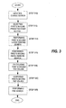
- a coarse motion estimation search is initiated.
- a coarse search involves diamond searches that involve five checking points. Other types of coarse searches may be implemented as well.
- a first predicted start motion vector associated with a first macroblock and a second predicted start motion vector associated with a second macroblock are selected as the starting positions of the coarse search. The selection of the first and second starting points are substantially similar to that discussed in the sequential searches embodiment of Figure 2 and are not further discussed here.
- Two large diamond searches which are substantially similar to steps 214 and 224 of Figure 2 , are performed concurrently using the first and second predicted start motion vectors (step 314). From the SADs calculated for each checking point relative to the pixels within the macroblock inside the reference frame, the vectors with the minimum SADs and the corresponding SAD values related to the first and second predicted start motion vectors are selected and stored.
- step 316 two small diamond searches, which are substantially similar to steps 216 and 226 of Figure 2 , are performed concurrently using the vectors and the corresponding minimum SADs values determined in step 314.
- the minimum SAD values of the two small diamond searches are determined. The vectors with the minimum SADs and the associated SAD values are stored in system memory.
- the minimum SAD values determined from the two small diamond searches are compared against each other (step 320).
- a fine search is performed in step 322.
- the fine search includes an 8x8 search and a half-pixel search which are substantially similar to those in step 232 of the Figure 2 .
- the fine search outputs a minimum SAD value along with the associated vector which are stored and passed to a motion compensation engine ending the parallel motion estimation process in accordance with the present invention.
- FIG. 5 illustrates, as an example, a high-level diagram of computer system 500 in which the present invention may be implemented or practiced. More particularly, computer system 500 may be a laptop or hand-held computer system. It is to be appreciated that computer system 500 is exemplary only and that the present invention can operate within a number of different computer systems including desktop computer systems, general-purpose computer systems, embedded computer systems, and others.
- computer system 500 is a highly integrated system which includes of integrated processor circuit 501, peripheral controller 502, read-only-memory (ROM) 503, and random access memory (RAM) 504.
- the highly integrated architecture allows power to be conserved.
- Peripheral controller 502 is optional if there is a need to interface with complex and/or high pin-count peripherals that are not provided in integrated processor circuit 501.
- Integrated processor circuit 501 comprises a processing unit 505, memory interface 506, graphics/display controller 507, direct memory access (DMA) controller 508, and core logic functions including encoder/decoder (CODEC) interface 509, parallel interface 510, serial interface 511, and input device interface 512.
- processing unit 505 integrates a central processing unit (CPU), a memory management unit (MMU), together with instruction/data caches.
- CODEC interface 509 provides the interface for an audio source and/or modem to connect to integrated processor circuit 501.
- Parallel interface 510 allows parallel input/output (I/O) devices such as hard disks, printers, etc. to connect to integrated processor circuit 501.
- Serial interface 511 provides the interface for serial I/O devices such as Universal Asynchronous Receiver Transmitter (UART), Universal Serial Bus (USB), and Firewire (IEEE 1394) to connect to integrated processor circuit 501.
- Input device interface 512 provides the interface for input devices such as keyboard, mouse, and touch pad to connect to integrated processor circuit 501.
- DMA controller 508 accesses data stored in RAM 504 via memory interface 506 and provides the data to peripheral devices connected to CODEC interface 509, parallel interface 510, serial interface 511, or input device interface 512. DMA controller 508 also sends data from CODEC interface 509, parallel interface 510, serial interface 511, and input device interface 512 to RAM 504 via memory interface 506. Graphics/display controller 507 requests and accesses the video/graphics data from RAM 504 via memory interface 506. Graphics/display controller 507 then processes the data, formats the processed data, and sends the formatted data to a display device such as a liquid crystal display (LCD), a cathode ray tube (CRT), or a television (TV) monitor. In computer system 500, a single memory bus is used to connect integrated processor circuit 501 to ROM 503 and RAM 504.
- LCD liquid crystal display
- CRT cathode ray tube
- TV television
- graphics/display controller 507 comprises CPU Interface Unit (CIF) 601, SRAM 602, Phase Lock Loop (PLL) circuit 603, oscillator 604, pixel processing logic 608, Graphics Engine (GE) 606, Memory Interface Unit (MIU) 607, Flat Panel Interface (FPI) 609, CRT Digital-to-Analog Converter (DAC) 610, post-processing module 611, MPEG-4 video decoder 612, and MPEG-4 video encoder 613.
- Graphics/display controller 507 further includes a video input port to accommodate a video camera.
- CIF 601 provides the interface to processing unit 505 and DMA controller 508. Accordingly, CIF 601 routes requests and video/image data received from processing unit 505 to the desired destination. In particular, CIF 601 sends register read/write requests and memory read/write requests from the host CPU processing unit 505 and DMA controller 508 to the appropriate modules in graphics/display controller 507. For example, memory read/write requests are passed on to MIU 607 which in turn reads/writes the data from/to the frame buffer in SRAM 602. CIF 601 also serves as the liaison with DMA controller 508 to fetch data from system memory (ROM 503 and RAM 504) and provides the data to GE 606 and MIU 607.
- CIF 601 has a number of control registers which can be programmed by the host CPU in processing unit 505 to control the MPEG post-processing process (e.g., the content of some of the control registers may be used to configure MPEG-4 decoder 612).
- CIF 601 also passes compressed video/image bitstream to MPEG-4 decoder 612 to perform image construction/decompression.
- CIF 601 further passes uncompressed video/image bitstream received from a source connected to codec interface 509 or serial interface 511 to MPEG-4 encoder to perform compression before the compressed bitstream can be transmitted to a device connected directly or remotely to integrated processor circuit 501. Accordingly, MPEG-4 encoder 613 implements the motion estimation technique of the present invention.
- the frame buffer in SRAM 602 is used to store the pixmap (i.e., a pixel pattern mapped into the frame buffer) of the image to be displayed on the monitor as well to act as a temporary buffer for various purposes. Additionally, SRAM 602 may have memory allocated for video buffers and transactional registers. The transactional registers can be used to store quantization factors for each block of video image pixel data. However, the transactional registers used in storing quantization factors are preferably implemented inside MPEG-4 decoder 612. GE 606 processes graphics/video image data which is then stored in the buffer in SRAM 602 based on commands issued by the host CPU.
- GE 606 performs graphics operations (e.g., BitBLTs and ROPs, area fills, line drawing) and provides hardware support for clipping, transparency, rotation, and color expansion.
- graphics operations e.g., BitBLTs and ROPs, area fills, line drawing
- GE 606 through a built-in Stretch Block Transfer (STRBLT) function further performs video image expansion, progressive scanning conversion, YcbCr (YUV) to RGB color-space conversion, etc.
- GE 606 frees processing unit 505 from the video/image display rendering function to allow processing unit 505 to perform time-critical or real-time operations.
- MIU 607 controls all read and write transactions from/to the frame buffer, video buffers, and transactional registers in SRAM 602. Such read and write requests may come from the host CPU via CIF 601, GE 606, pixel processing logic 608, FPI 609, etc. In addition, MIU 607 performs tasks associated with memory addressing, memory timing control, and others.
- Post-processing module 611 removes blocking and ringing artifacts from decompressed MPEG video image data to improve the quality of the decompressed video data.
- the decompressed MPEG video image data can be received from, for example, an optical media player via serial interface 511 or MPEG-4 decoder 612. The filtered video image data is then sent to SRAM 602.
- Pixel processing logic 608 retrieves video/image data from the buffers in SRAM 602 via MIU 607, serializes the image data into pixels, and formats the pixels into predetermined formats before outputting them to FPI 609 or CRT DAC 610. Accordingly, pixel processing logic 608 generates the required horizontal and vertical display timing signals, memory addresses, read requests, and control signals to access image data stored in SRAM 602. If the display device involved is a LCD, pixel data from pixel processing logic 608 is sent to FPI 609 before being passed on to the LCD. FPI 609 further processes the data by further adding different color hues or gray shades for display.
- FPI 609 formats the data to suit the type of display. Furthermore, FPI 609 allows color data to be converted into monochrome data in the event a monochrome LCD is used. Conversely, if the display device is a cathode ray tube (CRT), pixel data is provided to CRT digital-to-analog converter (DAC) 610 prior to being sent to the CRT. CRT DAC 610 converts digital pixel data from pixel processing logic 608 to analog Red Green and Blue (RGB) signals to be displayed on the CRT monitor.
- CTR cathode ray tube
- DAC digital-to-analog converter
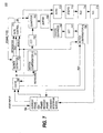
- MPEG-4 video encoder 613 includes motion compensator (-) (MC-) 701, DCT module 702, quantizer 703, memory 704, buffer 705, inverse quantizer 706, Inverse DCT (IDCT) module 707, motion compensator (+) (MC+) 708, cache 709, motion estimator 710, rate control module 711, alternative coefficient/discrete coefficient (AC/DC) module 712, zigzag (ZZ) module 713, run-length coding (RLE) module 714, and variable length coding (VLC) 715.
- Video input from a source such as a video camera connected to system 500 is provided to memory 704.
- the video input from the source is the current video frame data.
- memory 704 is separated into a current frame area to store data from the current video input, a reference frame/reconstructed frames area to store data from the reference video frame and data from a video frame reconstructed from compression, and an encoded bitstream buffer to store data from a freshly encoded video frame by encoder 613.
- Cache 709 fetches current video frame data from memory 704 one macroblock at a time and reference video frame data several macroblocks at a time (these several macroblocks are adjacent neighbors).
- Cache 709 receives as input the motion vectors associated with the "good" match video block determined from motion estimator 710.
- Cache 709 provides data from the current video frame and data from the reference video frame to MC- 701 and motion estimator 710 based on the motion vectors of the "good” match video block received. Cache 709 also provides data from the reference video frame to MC+ 708 based on the motion vectors of the "good” match video block received.
- MC- 701 is essentially a subtractor in which prediction data from a reference video frame is subtracted from data from a current video frame, which has been presented in the correct order for encoding according to the desired Group Of Pictures (GOP) structure.
- the subtractor is disabled (e.g., the prediction is set to zero) for I-frames or I- macroblocks.
- the output of MC- 701, which is the prediction error (or the video input in the case of I-frames) is passed to DCT module 702 which performs the Discreet Cosine Transformation and outputs DCT coefficients to quantizer 703.
- Quantizer 703 carries out the quantization process which may be generalized as a step to weight the DCT coefficients based on the amount of noise that the human eye can tolerate at each spatial frequency so that a reduced set of coefficients can be generated.
- the quantized DCT coefficients are provided to buffer 705 for temporary storage before they are passed on to AC/DC module 712 and inverse quantizer 706.
- AC is typically defined as a DCT coefficient for which the frequency in one or both dimensions is non-zero (higher frequency).
- DC is typically defined as a DCT coefficient for which the frequency is zero (low frequency) in both dimensions.
- AC/DC module 712 predicts the AC and DC for the current block based on AC and DC values of adjacent blocks such as an adjacent left top block, a top block, and an adjacent left block. For example, the prediction can be made as follows:
- AC/DC module 712 provides the AC and DC predicted coefficients to ZZ module 713 which forms a 64-elements long vector such that the low frequency (e.g., DC) components are placed at the beginning of the vector.
- ZZ module 713 provides the 64-elements vector to RLE module 714 which basically determines the number of consecutive zeros in the vector and forms RLE acceptable words based on the determination. After quantization, there are likely a significant number of zeros (likely to be the high frequency components) in the block and there is no need to transmit or store such information. Accordingly, a RLE word represents the number of zeros between consecutive non-zero elements in the vector. The RLE word also includes the value of the last non-zero element after the zeros and information indicating whether this value is the very last component in the vector.
- the RLE words are provided to VLC module 704 which maps RLE words into VLC patterns. For example, certain RLE words are given specific bit pattern. The most common RLE words are given the shortest VLC bit pattern. VLC patterns are specified in MPEG-4 standard. (See “MPEG-4 Information Technology-Coding of Audio-Visual Objects-Part 2: Visual" ISO/IEC/14496-2:1999). Run-length and variable-length coding (the combination coding is commonly referred to as Huffman coding).
- VLC and run-length encoding are used to exploit this distribution characteristic to identify non-zero DCT coefficients from zero DCT coefficients. In so doing, redundant/predictable information can be removed.
- the encoded (i.e., compressed) block of video frame data is then sent to memory 704 for storing in the encoded frame cache.
- the process of motion compensated prediction requires a signal on which to base the prediction.
- This signal represents the reference/previous video frame data which is stored in the reference cache of memory 704.
- a local decoder is included in video encoder 613 to generate a locally decoded signal in the encoder.
- the local decoder which consists of inverse quantizer 706, IDCT 707, and MC+ 708, basically undoes the encoding stages of quantizer 703 and DCT 702 to produce a decoded prediction error and adds it back into a suitably delayed version of the prediction (reference frame) data to produce a locally decoded (reconstructed) signal with motion compensation.
- the delayed prediction data is provided by cache 709.
- motion estimator 710 For each macroblock in the current video frame, motion estimator 710, which implements the present invention, searches for a "good" matched macroblock in the reference video frame based on a minimum SAD value. Motion estimator 710 receives as input blocks of current frame and reference frame data. Motion estimator 710 also receives a signal indicating the frame type from rate control module 711. Motion estimator 710 also determines the motion vector. Motion estimator 710 further determines whether a macroblock in the current video frame is intra (encoded independently) or inter (encoded after motion compensation). These determinations are communicated to rate control module 711. The motion vector determinations are communicated to cache 709 and MC+ 708.
- Rate control module 711 is used to control the average bit rate at the bitstream buffer in memory 704 to stay inside an acceptable limit range to prevent overflow and underflow. To achieve the average bit rate control, rate control module 711 varies the quantization factors in quantizer 703 and AC/DC module 712.
- rate control module 711 takes into consideration the expected differences (e.g., through modeling projection) in bit rates generated by I and P frames.
- motion estimator 710 comprises motion vector calculator 801, SRAM 802, macroblock address calculator 803, scheduler 804, intra/inter decision block 805, standard deviation calculator 806, diamond SAD array 807, diamond search controller 808, 8x8 SAD array 809, 8x8 search controller 810, compare & motion vector generation block 811, and programmed registers 812.
- Motion vector calculator 801 receives reference pixel address information and search pixel address information from a reference cache and a search cache (both not shown) that store a reference video frame and a current video frame, respectively.
- motion vector calculator 801 determines the motion vectors between corresponding macroblocks in the reference frame and the current frame during a search process controlled by scheduler 804. Motion vector calculator 801 provides the motion vector information determined to the reference cache, the search cache, SRAM 802, scheduler 804, and compare & motion vector generation module 811.
- Macroblock address calculator 803 receives a signal from scheduler 804 and search pixel addresses from the search cache. Calculator 803 computes the address of the search (current) block (macroblocks or 8x8 blocks) which contains the search pixel addresses based on the signal from scheduler 804 and provides the macroblock addresses to motion vector calculator 801 for determining the motion vectors of the corresponding blocks.
- the signal from scheduler 804 may involve information related to checking points that allows macroblock address calculator 803 to determine which macroblock address to compute.
- SRAM 802 stores the motion vector for the 8x8 pixels block related to the LEFT macroblock and/or the motion vector for the 8x8 pixels block related to the UP macroblocks relative to the current macroblock in the current video frame. SRAM 802 is updated after each current macroblock is finished.
- the motion vectors for the UP and LEFT macroblocks are used as first and second predicted start vectors, respectively, in accordance with the preferred embodiment of the present invention. Whether one or two predicted start vectors are provided by SRAM 802 depends on a signal provided by programmed registers 812 which is controlled by the CPU.
- SRAM 802 provides either the UP or LEFT motion vector as the predicted start vector to scheduler 804 and diamond search controller 808.
- diamond search controller 808 Using the predicted start vector from SRAM 802, current minimum SAD from compare & motion vector generation module 811, the associated motion vectors from motion vector calculator 801, together with reference and current (search) pixel information (e.g., intensity level for a pixel), which are stored in diamond SAD array 807 in a format recognizable by diamond search controller 808, diamond search controller 808 carries out the steps of a large diamond search and a small diamond search that were discussed earlier. Whether a large diamond search or small diamond search is performed depends on the instruction given by scheduler 804. Scheduler 804 also provides diamond search controller with the offset step (e.g., four, one, or one-half pixel), the checking points, and constant FAVOR_0.
- the offset step e.g., four, one, or one-half pixel
- the minimum SAD value Minsad computed from the large diamond search or small diamond search by diamond search controller 808 is passed to compare & motion vector generation module 811 which monitors and stores the minimum SAD during the entire motion estimation process as well as monitors and stores the motion vector associated with the block (either macroblock or 8x8 block) in which the minimum SAD locates. Compare & motion vector generation module 811 outputs the updated minimum SAD value and the associated motion vector.
- diamond search controller 808 further receives the updated minimum SAD value and the associated motion vector resulted from the large diamond search from compare & motion vector generation module 811.
- Diamond search controller 808 also receives a signal indicating whether a second search (see step 220 of Figure 2 ) using a second predicted starting vector is to be carried out from programmed registers 812.
- 8x8 search controller 810 Using reference and current (search) pixel information (e.g., intensity level for a pixel), which are stored in 8x8 SAD array 809 in a format recognizable by 8x8 search controller 810, and the updated minimum SAD value together with the associated motion vector resulted from the small diamond search from compare and motion vector generation module 811, 8x8 search controller 810 carries out the steps of a 8x8 search that was discussed earlier.
- Scheduler 804 initiates the 8x8 search process carried out by 8x8 search controller 810.
- Scheduler 804 also provides 8x8 search controller 810 with the offset step, the value of FAVOR_16x16, and the checking points.
- the minimum SAD value Minsad computed from each 8x8 search by controller 810 is used to compute ⁇ SAD(8x8) which is then compared against [SAD(16x16) - FAVOR_16x16]. Depending on the result of the comparison, either the SAD and the motion vector of one macroblock or four SADs and motion vectors of four 8x8 blocks are provided to compare & motion vector generation module 811. 8x8 search controller 810 also provides signal mv4flag to scheduler 804 indicating whether four 8x8 block motion vectors or one macroblock motion vector are used.
- Diamond search controller 808 also performs the half-pixel search discussed earlier in step 232 using inputs such as the four minimum SAD values and the associated motion vectors for the four 8x8 pixels blocks (or the minimum SAD value and the associated motion vectors for the macroblock) from compare & motion vector generation module 811, the offset step and the checking points from scheduler 804, and reference and current (search) pixel information (e.g., intensity level for a pixel), which are stored in diamond SAD array 807.
- Scheduler 804 initiates the half-pixel search carried out by diamond search controller 808 and indicates whether such half-pixel search involves one motion vector for a macroblock or four motion vectors for four 8x8 blocks.
- the minimum SAD value Minsad computed from the diamond search controller 808 is passed to compare & motion vector generation module 811 which monitors and stores the minimum SAD during the entire motion estimation process as well as monitors and stores motion vectors (e.g., associated with the block, which may be either macroblock or 8x8 pixels, in which the minimum SAD locates, checking points etc.). Compare & motion vector generation module 811 outputs the minimum SAD value and the associated motion vector.
- scheduler 804 monitors and controls the motion estimation process in accordance with the present invention.
- scheduler 804 is a state machine that can be configured to carry out the steps of either Figure 2 (i.e., carry out the motion estimation process serially) or Figure 3 (i.e., carry out the motion estimation process in parallel). If a serial motion estimation process is implemented, scheduler 804 also determines whether a second coarse search is to be carried out.
- Scheduler 804 receives as input at least the first and second predicted start points from SRAM 802, signal indicating whether an 8x8 search is enabled from programmed registers 812, signal indicating whether a half-pixel search is enabled from programmed registers 812, and the frame type signal from rate control module 711.
- MAD Mean And Standard Deviation
- Intra/inter decision module 805 which additionally receives the final minimum SAD value (resulted from the motion compensated estimation process) from compare & motion vector generation block 811 via scheduler 804, intra/inter decision block 805 determines whether the macroblock is I-encoded or P-encoded (i.e., I coding mode or P coding mode) and outputs intra/inter signal to so indicate.
- intra/inter decision module 805 indicates that a macroblock is I-encoded if the MAD value is less than or equal to the minimum SAD value. If the macroblock is I-encoded, the motion vector is set to zero and the minimum SAD value of the motion compensated estimation process is set to the MAD value. Otherwise, intra/inter decision module 805 indicates that the macroblock is P-encoded if the MAD value is greater than the minimum SAD value. If the macroblock is P-encoded, the minimum SAD value and its associated motion vector currently stored in compare and motion vector generation moduel 811 are output.
Landscapes
- Engineering & Computer Science (AREA)
- Multimedia (AREA)
- Signal Processing (AREA)
- Compression Or Coding Systems Of Tv Signals (AREA)
- Image Analysis (AREA)
- Compression, Expansion, Code Conversion, And Decoders (AREA)
- Measuring Pulse, Heart Rate, Blood Pressure Or Blood Flow (AREA)
Abstract
Description
- The invention generally relates to computer systems, and more particularly relates to MPEG motion estimation.
- Moving Pictures Experts Groups (MPEG) is an International Standards Organization (ISO) standard for compressing video data. Video compression is important in making video data files, such as full-length movies, more manageable for storage (e.g., in optical storage media), processing, and transmission. In general, MPEG compression is achieved by eliminating redundant and irrelevant information. Because video images typically consist of smooth regions of color across the screen, video information generally varies little in space and time. As such, a significant part of the video information in an image is predictable and therefore redundant. Hence, a first objective in MPEG compression is to remove the redundant information and leaving only the true or unpredictable information. On the other hand, irrelevant video image information is information that cannot be seen by the human eye under certain reasonable viewing conditions. For example, the human eye is less perceptive to noise at high spatial frequencies than noise at low spatial frequencies and less perceptive to loss of details immediately before and after a scene change. Accordingly, the second objective in MPEG compression is to remove irrelevant information. The combination of redundant information removal and irrelevant information removal allows for highly compressed video data files.
- MPEG compression incorporates various well-known techniques to achieve the above objectives including: motion-compensated prediction/estimation, Discrete Cosine Transform (DCT), quantization, and Variable-Length Coding (VLC). In general, prediction/estimation is a process in which past information is used to predict/estimate current information. There is typically a difference/error between the past information used and the actual/current information. As part of the compression scheme, this difference (instead of the actual/current video information) is transmitted for use in° reconstructing/decoding a compressed video frame by essentially adding it to existing past information that may be referred to as a reference frame. How well the decompression process performs depends largely on the estimate of this difference. When successive video frames involve moving objects, the estimate must also include motion compensation.
This is done through the use of motion vectors which are the displacement measurements of objects between successive video frames. These motion vectors are then additionally transmitted as part of the compression scheme to be used in reconstructing/decoding the compressed video frame. - One of the motion-compensated estimation techniques that is most suitable for hardware implementation due to its consistency and simplicity is block matching. In block matching, motion is estimated on the basis of blocks and a motion vector is generated for each block under the assumption that all the pixels within a block have the same motion activity. In short, a block from a search area in the reference video frame (i.e., a frame that has been received and/or processed previously) is identified through a search based on a match selection criteria relative to a block from a present frame. Such selection criteria is typically designed to ensure a minimized estimation difference. The most effective search but also the most processing and computing intensive is a full exhaustive search in which every block within the search area is examined and corresponding computation made. If a search area is limited to ±16 pixels displacement in the X and Y directions, then the total number of matches need to be made is approximately (2*(16)+1)2 = 1089.
The match selection criterion used for the full search may be the Sum of Absolute Difference (SAD) (other match selection criteria include mean absolute difference, mean square difference, etc.). The SAD for a block A of size NxN inside the current frame compared to a block B of a distance (•x, •y) from A in the previous (or reference) frame is defined as:
where I is the intensity level of a pixel. - As shown in the SAD equation above, an addition and a subtraction operation are required for each pixel match. Hence, an approximate total of 2178 operations are required for each pixel match in a full search. Consequently, each macroblock (16x16 pixels) requires approximately 2178 x 256 or 557K operations which is processor intensive and therefore undesirable. The corresponding blocks from the current frame and the reference frame with the smallest SAD value are then selected as the best matched (i.e., having the least difference/error) for transmission as compression information. The associated motion (displacement) vector is computed from the selected pair of blocks for use as motion compensation information.
- To reduce the processing needed while minimizing estimation difference/error, other search techniques have been developed. One such search techniques is the Diamond Search (DS). In a DS, which is based on the assumption that motion vectors are in general center biased, a search area (in a block in the reference frame) includes nine checking points as shown for example in
Figure 1A . The search begins with an examination of the center checking point of the search area. This portion of the search (e.g., involving nine checking points) is known as a Large Diamond Search (LDS). If the minimum SAD is found at the center, then four additional checking points representing a smaller diamond, as shown inFigure 1B , are examined and the search stops. The portion of the search (e.g., involving 4 additional checking points) is known as a Small Diamond Search (SDS). Otherwise, depending on the position of the current minimum, additional checking points will have to be examined as shown for example inFigures 1C and 1D . By considering the present minimum as the new center of a new large diamond created, the process continues until the minimum which is a center point is found. At which point, a smaller diamond with four additional checking points are examined. A discussion of the DS is presented for example in "A New Predictive Diamond Search Algorithm for Block Based Motion Estimation" by A. Tourapis, G. Shen, M. Liou, O. Au, and I. Ahmad, Proc. Of SPIE Conf. On Visual Communication and Image Processing, Vol. 3, pp. 1365-1373, 20-23 Jun 2000. This material is incorporated herein by reference in its entirety. - While DS typically requires only a fraction of the processing required in a full search, a DS is susceptible to getting caught up with local minimums which are not desirable because they may not represent the best matched macroblock. In other words, while the DS search relies on the inherent center-biased nature of motion vectors and allows for iteration searches to examine additional checkpoints, it has no mechanism to ensure that the minimum SAD can be quickly determined.
- Moreover, the paper "A New Predictive Diamond Search Algorithm for Block Based Motion Estimation" cited above takes advantage of the high correlation of neighboring macroblocks (and therefore their associated motion vectors) and use as the starting point of the DS the median value of the motion vectors of three neighboring blocks: left macroblock LMB relative to the current macroblock that is designated the center of the search area, up macroblock UMB relative to the current macroblock that is designated the center of the search area, and up-right macroblock URMB relative to the current macroblock that is designated the center of the search area. In other words, instead of using the center pixel of the diamond as a starting point, the median of these three neighboring blocks is used. By taking into consideration the correlation between adjacent macroblocks (and their associated motion vectors), an improved prediction can be made thereby shortening the search.
- Furthermore, in MPEG-4, in addition to a stage involving the aforementioned DS which is an integer pixel motion estimation, a half-pixel motion estimation stage may be implemented. As its name suggests, a half-pixel motion estimation involves a search of checking points that are at a half-distance between two checking points of the integer pixel motion estimation search. The half-distance can easily be interpolated from the checking points of the integer pixel motion estimation search. The half-pixel motion estimation stage is designed to improve the accuracy of motion vectors. See "A New Predictive Diamond Search Algorithm for Block Based Motion Estimation" by W. Zheng, I. Ahmad, and M. Liou, International Conf. on Information Systems, Analysis and Synthesis, SCI2001/ISAS 2001 Vol. 13,2001. It is desirable to reduce even further the processing required for motion-compensated estimation which translates to less power and smaller die size required.
-
US Pat. 6 195 389 discloses techniques for performing motion estimation in which a best match for a current block is located by comparing the current block of the picture currently being encoded with candidate blocks that are located using the motion vectors of blocks that are either spatially or temporally proximate to the current block. - Published UK patent application
GB 2 348 559 - H.M. Jong et al. in "Accuracy Improvement and Cost Reduction of 3-Step Search Block Matching Algorithm for Video Coding," IEEE Trans. On Circuits and Systems for Video Tech., IEEE Service Center, Piscataway NJ, US vol. 4, no. 1, Feb. 1, 1994, pgs 88-90, discusses a technique for avoiding local minimums, whereby multiple candidate start points are retained and used in one of a plurality of parallel-occurring three-step hierarchical searches.
- In view of the foregoing, a need exists for a more efficient, less complex, and effective motion-compensated estimation technique that can be easily implemented in hardware.
- Accordingly, the present invention provides a more efficient, less complex, and effective motion-compensated estimation technique that can be easily implemented in hardware.
- The present invention meets the above need with a motion estimation technique that involves selecting a plurality of predicted start motion vectors, performing coarse searches using the plurality of predicted start motion vectors (either sequentially or in parallel), determining a Sum of Absolute Difference (SAD) value and the associated vector from the coarse searches, and performing a fine search using the vector determined from the coarse searches as a starting position.
- In the preferred embodiment, the plurality of predicted start motion vectors are two (2) start motion vectors related to the macroblock that is immediately above the current macroblock (a.k.a. the UP macroblock) and the macroblock that is immediately on the left of the current macroblock (a.k.a. the LEFT macroblock).
In accordance with the present invention, the correlation between adjacent macroblocks (and their associated motion vectors) is utilized by using two predicted starting points based on adjacent macroblocks. This results in an improved prediction (especially for fast motion videos) which in turn shortening the search. - In the preferred embodiment, the coarse searches are 16x16 Diamond Searches (DS) and the fine search involves an 8x8 search and a half-pixel search. More particularly, the DS's are based on a 5-Steps Diamond Search (5SDS). 5SDS involves five checking points. As a result of the use of a plurality of predicted starting points as well as other improvements, the processing required for carrying out the whole search is significantly reduced thereby rendering an efficient motion estimation technique that requires minimal system resources (e.g., hardware resources and CPU processing).
- All the features and advantages of the present invention will become apparent from the following detailed description of its preferred embodiment whose description should be taken in conjunction with the accompanying drawings.
-
-
Figures 1A-1D illustrate how a prior-art Diamond Search (DS) is carried out. -
Figure 2 is a high level flow chart of the steps carried out in the sequential searches embodiment of the present invention. -
Figure 3 is a high level flow chart of the steps carried out in the parallel searches embodiment of the present invention. -
Figure 4 illustrates the relative positions of a current macroblock, an UP macroblock, and a LEFT macroblock in a video frame in accordance with the present invention. -
Figure 4A illustrates large diamond search ofsteps -
Figures 4B-4C illustrate, for example, the first two iterations/steps of the small diamond search ofsteps -
Figures 4D-4E illustrate, for example, the two steps of the 8x8 block search ofstep 218 in accordance with the present invention. -
Figures 4F-4G illustrate, for example, the two steps of a half-pixel search ofstep 218 in accordance with the present invention. -
Figure 5 illustrates, as an example, a high-level diagram ofcomputer system 500 in which the present invention may be implemented or practiced. -
Figure 6 illustrates in greater detail graphics/display controller 507 that implements an embodiment of the present invention. -
Figure 7 illustrates a block diagram ofMPEG Video encoder 613 that implements an embodiment of the present invention. -
Figure 8 illustrates in greater detail a block diagram of motion compensatedestimator 710 that implements an embodiment of the present invention - In the following detailed description of the present invention, numerous specific details are set forth in order to provide a thorough understanding of the present invention. However, it will be obvious to one skilled in the art that the present invention may be practiced without these specific details. In other instances well known methods, procedures, components, and circuits have not been described in detail as not to unnecessarily obscure aspects of the present invention. While the following detailed description of the present invention is related to MPEG compressed video image data, it is to be appreciated that the present invention is also applicable to other video compression schemes.
- The motion estimation technique in accordance with the present invention utilizes a plurality of predicted start points (e.g., two predicted start points) based on blocks adjacent to the current block together with other improvements to provide a more efficient motion estimation process that requires minimal system resources (e.g., hardware resources and CPU processing) in its hardware implementation. More particularly, the motion estimation technique in accordance with the present invention performs a plurality of coarse searches (either sequentially or in parallel) using a plurality of start motion vectors followed by a fine search.
- Referring now to
Figure 2 illustrating a high level flow chart of the steps carried out in the sequential searches embodiment of the present invention. Instep 210, a coarse motion estimation search is initiated. In the preferred embodiment, a coarse search involves diamond searches that involve five checking points. Other types of diamond searches may be implemented as well. Next, instep 212, a first predicted start motion vector associated with a macroblock is selected as the starting position of the coarse search. Depending on the encoded mode associated with the current video macroblock as shown ascurrent macroblock 412 ofFigure 4 , either predict start motion vector V0 is set to (0,0) or to the motion vector of8x8 block 418 whose position relative to the current macroblock in the current frame is illustrated inFigure 4 . In particular, as shown inFigure 4 ,8x8 block 418 is the lower left 8x8 block of UP macroblock 414 adjacent tocurrent macroblock 412. The encoded mode indicates whether the current macroblock is an Inter macroblock that is predicted from past information such as a previous video frame or an Intra macroblock that is not based on any past information (i.e., no motion estimation is needed). - In scenario 1, if the encoded mode of
current macroblock 412 is set as Intra (a.k.a, I-encoded), typically a whole frame is Intra, no estimation search is performed. In scenario 2, if the encoded mode ofcurrent macroblock 412 is set as Inter (a.k.a. P-encoded) andUP macroblock 414 is Inter then starting point V0 is set to the motion vector ofUP 8x8 block 418. In scenario 3, if the encoded mode ofcurrent macroblock 412 is set as Inter (a.k.a. P-encoded) andUP macroblock 414 is Intra then starting point V0 is set to (0,0). Inscenario 4, if the encoded mode ofcurrent macroblock 412 is set as Inter (a.k.a. P-encoded) andUP macroblock 414 is out of video range, the current macroblock is considered an I-encoded macroblock and the starting point is set to (0,0). - Alternatively, for scenario 2, the start motion vector V0 can also be set to the motion vector of any of the remaining 8x8 blocks of UP macroblock 414 or to the motion vector of
UP macroblock 414 itself. Or, the starting point V0 can be set to the motion vector of an 8x8 block in LEFT macroblock 416 or the motion vector of LEFT macroblock 416 itself whose position relative tocurrent macroblock 412 incurrent frame 400 is illustrated inFigure 4 as long as such motion vector is different from the one selected as the second predicted start motion vector (see step 222). Or the starting point V0 can be set to the motion vector of an 8x8 block in another macroblock in the proximity ofcurrent macroblock 412 as long as such motion vector is different from the one selected as the second predicted start motion vector (see step 222). The motion vector of8x8 block 418 orUP macroblock 414 is determined using an 8x8 search algorithm (described, for example, in greater detail instep 232 below) or a 5SDS (described, for example, in greater detail instep 216 below), respectively. - Using the first predicted start motion vector selected in
step 212, a large diamond search is performed (step 214). A description of this large diamond search is provided below. The large diamond search involves searching the checking points (V0.x,V0.y), (V0.x,V0.y+4), (V0.x,V0.y-4), (V0.x+4,V0.y), and (V0.x-4,V0.y) located in the current video frame which correspond to motion vectors V0, V0+(0,4), V0-(0,4), V0+(4,0), and V0-(4,0). The first predicted start motion vector is the center of the five checking points. As indicated, the step offset is 4 pixels. In this large diamond search, which is illustrated inFigure 4A , the Sum of Absolute Difference (SAD) of the five checking points inside the current frame is computed relative to the pixels inside a selected macroblock inside the reference/previous frame is defined as:
where IV is the intensity level of the pixels inside the macroblock inside the previous frame, ICP is the intensity level of the pixel at a checking point inside the current frame, and N is 16 (the number of rows and the number of columns in macroblock). - Essentially, the SAD value indicates how well a particular block in the current frame matches a block at a position in the previous frame. The smaller the SAD value the better match it is. SAD calculation is center-biased. If the vector associated with a pixel position for which a SAD value is computed is a center point (0,0), the SAD(v) value is subtracted by a predetermined factor FAVOR_0 preferably set at 129 to favor the selection of this vector as the one having the minimum SAD. In so doing, SAD calculation is ensured to be center biased. Additionally, if the range of the X or Y component of a motion vector exceeds [-15, 15], then the SAD associated with this vector is maintained at the maximum allowable SAD value of 255x256. In other words, when the X or Y component of a motion vector exceeds the allowable range, the motion vector is excluded by assigning a large SAD value to it.
- From the SADs calculated for each checking point relative to the pixels within the macroblock inside the reference frame, the pixel position (hereinafter referred to as vector) with the minimum SAD and the corresponding SAD value are selected and stored. Preferably, the search order for the checking points is V0-(4,0), V0, V0+(4,0), V0-(0,4), and V0+(0,4).
- In terms of computation operations, for a large diamond search, the SAD value calculation for each vector inside the macroblock associated with the first predicted start motion vector requires 5 (checking points) x 2 (one addition operation and one subtraction operation)= 10 operations.
- Next, using the vector selected and stored in
step 214 as the starting position, a small diamond search based on a 5SDS algorithm is performed (step 216). The small diamond search involves searching the checking points (v.x,v.y), (v.x,v.y+1), (v.x,v.y-1), (v.x+1,v.y), and (v.x-1.v.y) located in the current video frame which correspond to motion vectors v (the motion vector stored in step 214), v+(0,1), v-(0,1), v+(1,0), and v-(1,0). As indicated, the step offset is 1 one pixel. The starting point is the center of the five checking points. The small diamond search ofstep 216 is similar to the large diamond search ofstep 214. Equation 1 from above is also used to calculate the SADs for the checking points relative to the pixels inside the macroblock inside the previous/reference frame. However, unlike the large diamond search instep 214 which finishes when the SADs for all checking points are computed and the relative minimum SAD among the five checking points is determined, the small diamond search instep 216 will finish if the pixel with the minimum SAD is the center of the diamond made up by the checking points or if the search iteration reaches four (4). -
Figures 4B-4C illustrate the first two iterations/steps of the 5SDS used in the small diamond search ofstep 216. In the first iteration of a small diamond search, a search area (in a block in the reference frame) includes five checking points (illustrated as circles) as shown for example inFigure 4B . The search begins with an examination of the center checking point of the search area. If the minimum SAD is found at the center, then the search is finished. If the pixel with the minimum SAD is not the center of the diamond, a new iteration involving a new diamond is initiated in which a new diamond consists of the checking point with the minimum SAD at the center surrounded by four checking points (some old and some new) with a relative step offset of one (shown inFigure 4C ). InFigure 4C , the old checking points from the first iteration are illustrated as circles and the new checking points in the second iteration are illustrated as triangles. This process is repeated until the pixel with the minimum SAD is the center of the diamond made up by the checking points or the search iteration reaches four (4). To reduce redundant search step, an effort can be made to monitor the checking points and/or their associated motion vectors to avoid the re-calculation of the SAD of the vector positions that have been calculated previously. Consider, for example,Figure 4C in which the circles are the checking positions that have been calculated in the previous iteration and the triangles are the additional checking positions that need to be calculated in the present iteration. In this example, only three new SAD calculations are needed in the second iteration as opposed to five SAD calculations required in the first iteration. Because the first SAD calculation was already performed and stored instep 214, there are only four SAD calculations required in the first iteration for the small diamond search. - In terms of computation operations, for a small diamond search, the SAD value calculation for each vector inside the macroblock associated with the first predicted start motion vector requires a maximum of (4+3+3+3)x2 = 26 operations. This is due to the maximum 4 iterations involved and the geometry of the diamond when the step offset is one which dictates that for each iteration there is one or two checking points that involve a recalculation of a vector position that have been calculated previously.
- In
step 218, the minimum SAD of the small diamond search is determined. The vector with the minimum SAD and the SAD value associated is stored in memory. Next, it is determined whether a second coarse search is required (step 220). To do so, the distance between the second predicted starting position motion vector and the motion vector having the minimum SAD value calculated and stored in step 218 (the result of the coarse search using the second predicted starting position) is computed and the result compared to a predetermined value. Preferably, this predetermined value is 4 which is selected because it represents a threshold above which the result of the first coarse search may be a local minimum. Hence, a second search is required if:
where V0 is the second predicted starting position (motion vector) and v is the motion vector associated with the minimum SAD stored instep 218. - If a second search is not needed, skip to step 232. On the other hand, if a second search is needed,
step 222 is performed to select a second predicted start motion vector associated with a macroblock as the starting position of the second coarse search. Depending on the encoded mode associated withcurrent video macroblock 412 ofFigure 4 , either predict start motion vector V0 is set to (0,0) or to the motion vector of8x8 block 420 whose position relative to the current macroblock in the current frame is illustrated inFigure 4 . As shown inFigure 4 ,8x8 block 420 is the upper right 8x8 block of LEFT macroblock 416 adjacent tocurrent macroblock 412. - In scenario 1, if the encoded mode of
current macroblock 412 is set as Intra (a.k.a, I-encoded), typically a whole frame is Intra, no estimation search is performed. In scenario 2, if the encoded mode ofcurrent macroblock 412 is set as Inter (a.k.a. P-encoded) andUP macroblock 414 is Inter then starting point V0 is set to the motion vector ofUP 8x8 block 418. In scenario 3, if the encoded mode ofcurrent macroblock 412 is set as Inter (a.k.a. P-encoded) andUP macroblock 414 is Intra then starting point V0 is set to (0,0). Inscenario 4, if the encoded mode ofcurrent macroblock 412 is set as Inter (a.k.a. P-encoded) andUP macroblock 414 is out of video range, the current macroblock is considered an I-encoded macroblock and the starting point is set to (0,0). - Alternatively, for scenario 2, the start motion vector V0 can also be set to the motion vector of any of the three remaining 8x8 blocks of LEFT macroblock 416 or to the motion vector of LEFT macroblock 416 itself. Or, the starting point V0 can be set to the motion vector of an 8x8 block in UP macroblock 414 or the motion of UP macroblock 414 itself whose position relative to
current macroblock 412 in thecurrent frame 400 is illustrated inFigure 4 as long as such motion vector is different from the one selected as the second predicted start motion vector (see step 212). Or the starting point V0 can be set to the motion vector of an 8x8 block in another macroblock in the proximity of the current macroblock as long as such motion vector is different from the one selected as the second predicted start motion vector (see step 212). The motion vector of the 8x8 block or the UP macroblock is determined using an 8x8 search algorithm (described, for example, in greater detail instep 232 below) or a 5SDS algorithm (described, for example, in greater detail instep 216 above), respectively. - Using the second predicted start motion vector selected in
step 222, a large diamond search is performed (step 224). Because the large diamond search including the checking points is substantially similar to that described instep 214, it is not repeated here. As a result of the large diamond search, the vector and the associated minimum SAD value are stored separately from the vector and associated minimum SAD value that are the result of the first coarse search. Next, using the vector selected and stored instep 224 as the starting position, a small diamond search is performed (step 226). The small diamond search is substantially similar to that performed instep 216 and is not repeated here. - In
step 228, the minimum SAD of the small diamond search is determined. The vector with the minimum SAD and the SAD value associated are stored in memory separately from the vector and associated minimum SAD value that are the result of the first coarse search. Next, the minimum SAD value stored instep 218 and the SAD value stored instep 228 are compared to determine the vector with the smallest (minimum) SAD value (step 230). Using the vector with the smallest SAD value determined fromstep 230 as input, a fine search is performed instep 232. Preferably, the fine search includes an 8x8 diamond search followed by a half-pixel search. In essence, the fine search carries out the search in a narrow area to improve the resolution and accuracy of the search. - The 8x8 search may be disabled through a programmed register. In an 8x8 search, the search area, where the checking points are located, is reduced from 16x16 pixels (a macroblock) to 8x8 pixels, the number of checking points are nine in a square (instead of diamond) pattern, the center of nine checking points is the vector from
step 230, and there are only two steps/iterations.Figures 4D-4E illustrate the two iterations involved in the 8x8 search. The 8x8 search basically matches an 8x8 pixels block in the reference frame to an 8x8 block in the current frame. The steps involved in the 8x8 search are as follows. First, the macroblock associated with the vector having the minimum SAD value determined and stored instep 230 is divided into four 8x8 pixels blocks. For each 8x8 pixels block, a search involving nine adjacent checking points (as shown inFigure 4D ) located in an 8x8 pixels block in the current frame is carried out relative to an 8x8 pixels block in the reference frame is determined. In other words, for each 8x8 block in the current frame, the SADs for nine checking points relative to an 8x8 pixels block in the reference frame are computed according to equation (1) with N= 8. From the nine SADs computed, a minimum SAD is selected. If the checking point associated with the minimum SAD is the center checking point, the 8x8 search is finished. If the checking point associated with the minimum SAD value is not the center checking point, then a second iteration search involve 9 checking points (some old and some new) is carried out (shown inFigure 4E ). InFigure 4E , the old checking points from the first iteration are illustrated as circles and the new checking points in the second iteration are illustrated as squares. As shown inFigure 4E , the nine checking points includes four circles and five squares. From the nine SADs computed according equation (1) in the second iteration, a minimum SAD is selected. For each 8x8 block in the current frame, the minimum SAD value and the motion vector of the associated 8x8 block is stored. - In terms of computation operations, for an 8x8 search, the SAD value calculation for each vector inside the 8x8 pixels block of the reference frame requires a maximum of [(9)x2] + (5*2) = 28 operations.
- The sum of the four minimum SADs of the four 8x8 blocks (subdivided from the macroblock) is then computed and stored. In shorthand, this sum can be referred to as ΣSAD(8x8). Next a determination is made to determine whether ΣSAD(8x8) is greater than the smallest SAD value stored in
step 230 minus FAVOR_16x16. FAVOR_16x16 is a weight factor preset to 129 to favor the selection of the minimum SAD associated with a macroblock which is stored instep 230. If it is, the new minimum SAD value is set to ΣSAD(8x8) and set flag mv4flag to 1 to indicate that four motion vectors (MV4) from four 8x8 blocks are used. The four minimum SAD values along with the four motion vectors associated with the four vectors having the minimum SADs are then stored in memory. Otherwise, the vector and the smallest SAD value determined fromstep 230 are maintained and set flag mv4flag to 0 indicating that only one motion vector is required for each macroblock. - In the preferred embodiment, the half-pixel search is performed as part of the fine search following the 8x8 search. The half-pixel search may be disabled through a programmed register. The same search steps apply whether one macroblock motion vector is involved or four 8x8 pixels block motion vectors are involved. First, flag mv4flag is checked. If mv4flag = 0 indicating one macroblock motion vector is involved, the vector with the smallest SAD value stored in
step 230 is used as a starting point. In addition, four half-pixel positions (hereinafter half-pixel vectors) relative to the starting point are determined. Hence, assuming the starting vector is (v.x,v.y), then the four half-pixel vectors are (v.x,v.y+1/2), (v.x,v.y-1/2), (v.x+1/2,v.y), and (v.x-1/2,v.y). The corresponding motion vectors are v, v+(0,1/2), v-(0,1/2), v+(1/2,0), and v-(1/2,0). These five vectors serve as the five checking vector wherein the step offset is ½ pixel. The intensity value of a half-pixel vector is determined by averaging the intensity values of the top and bottom pixels (whose offset distance is one) or the left and right pixels (whose offset distance is one) between which the half-pixel vector is located. If the half-pixel vector is located in the center of four pixels whose offset distances are one, then the intensity value of that half-pixel vector is determined by averaging the intensity values of these four pixels. -
Figure 4F illustrates the five checking points involved in the first step of a half-pixel search. Equation (1) is used to determine the SAD values for all five checking points. The minimum SAD value is then determined from five SAD values computed. Depending on which checking point yields the minimum SAD value, a second search step in which the SADs for additional checking points may be necessary. Table 1 below shows the additional checking points associated with the five original checking points that are required in the second search step. If a second step is required, the minimum SAD is determined from among the computed SAD values associated with the corresponding additional checking points and the "current" minimum SAD value determined from the five original checking points.Figure 4G illustrates the second step scenario where the checking point with the minimum SAD is (v.x+1/2, v.y). The minimum SAD and the vector having the minimum SAD is stored in memory.Table 1 Checking Point With Minimum SAD Additional Checking Points Required (v.x, v.y) No Additional Checking Point (v.x+1/2, v.y) (v.x+1/2, v.y±1/2) (v.x-1/2, v.y) (v.x-1/2, v.y±1/2) (v.x, v.y+1/2) (v.x±1/2, v.y+1/2) (v.x, v.y-1/2) (v.x±1/2, v.y-1/2) - Conversely, if mv4flag = 1 indicating that four motion vectors are required for each macroblock, the same two steps search described above is applied to each 8x8 pixels block. For each 8x8 pixels block, the vector with the smallest SAD value stored in system memory at the conclusion of the 8x8 search is used as a starting point. In addition, four half-pixel vectors relative to the starting point are determined. Hence, assuming the starting vector is (v.x,v.y), then the four half-pixel vectors are (v.x,v.y+1/2), (v.x,v.y-1/2), (v.x+1/2,v.y), and (v.x-1/2,v.y). The corresponding motion vectors are v, v+(0,1/2), v-(0,1/2), v+(1/2,0), and v-(1/2,0). These five vectors serve as the five checking vector wherein the step offset is ½ pixel.
Figure 4F illustrates the five checking points involved in a half-pixel search. Equation (1) is used to determine the SAD values for all five checking points except N=8 to limit the search area to a 8x8 block. The minimum SAD value is then determined from five SAD values computed. Depending on which checking point yields the minimum SAD value, a second search step in which the SADs for additional checking points may be necessary. Table 1 above shows the additional checking points associated with the five original checking points that are required in the second search step. If a second step is required, the minimum SAD is determined from among the computed SAD values associated with the corresponding additional checking points and the "current" minimum SAD value determined from the five original checking points. - After the half-pixel searches for all four motion vectors associated with four 8x8 pixels blocks are carried out, the four computed "minimum" SADs are compared to each other to determine the smallest SAD value and the vector with this smallest SAD value. These information are stored in memory and provided to
rate control module 711 ending the serial motion estimation process in accordance with the present invention. - In terms of computation operations, for the half-pixel search, the worst case scenario is when 4 motion vectors are involved. In this case, the SAD value calculation for each vector in the half-pixel search requires 4*(1+1+1) operations for the first step and 2*(3+1+1) operations for the second step. The total number of operations per pixel for the half-pixel search are 22. The calculations include the half pixel interpolation as well as operations required for SAD calculation. The total number of operations for the entire motion compensated estimation process (assuming two coarse searches) in accordance with the present invention are 122.
- Referring now to
Figure 3 illustrating a high level flow chart of the steps carried out in the parallel searches embodiment of the present invention. Instep 310, a coarse motion estimation search is initiated. In the preferred embodiment, a coarse search involves diamond searches that involve five checking points. Other types of coarse searches may be implemented as well. Next, instep 212, a first predicted start motion vector associated with a first macroblock and a second predicted start motion vector associated with a second macroblock are selected as the starting positions of the coarse search. The selection of the first and second starting points are substantially similar to that discussed in the sequential searches embodiment ofFigure 2 and are not further discussed here. - Two large diamond searches which are substantially similar to
steps Figure 2 , are performed concurrently using the first and second predicted start motion vectors (step 314). From the SADs calculated for each checking point relative to the pixels within the macroblock inside the reference frame, the vectors with the minimum SADs and the corresponding SAD values related to the first and second predicted start motion vectors are selected and stored. Next, instep 316, two small diamond searches, which are substantially similar tosteps Figure 2 , are performed concurrently using the vectors and the corresponding minimum SADs values determined instep 314. Instep 318, the minimum SAD values of the two small diamond searches are determined. The vectors with the minimum SADs and the associated SAD values are stored in system memory. - Next, the minimum SAD values determined from the two small diamond searches are compared against each other (step 320). Using the vector with the smaller SAD value determined from
step 320 as input, a fine search is performed instep 322. The fine search includes an 8x8 search and a half-pixel search which are substantially similar to those instep 232 of theFigure 2 . The fine search outputs a minimum SAD value along with the associated vector which are stored and passed to a motion compensation engine ending the parallel motion estimation process in accordance with the present invention. - Reference is now made to
Figure 5 illustrates, as an example, a high-level diagram ofcomputer system 500 in which the present invention may be implemented or practiced. More particularly,computer system 500 may be a laptop or hand-held computer system. It is to be appreciated thatcomputer system 500 is exemplary only and that the present invention can operate within a number of different computer systems including desktop computer systems, general-purpose computer systems, embedded computer systems, and others. - As shown in
Figure 5 ,computer system 500 is a highly integrated system which includes ofintegrated processor circuit 501,peripheral controller 502, read-only-memory (ROM) 503, and random access memory (RAM) 504. The highly integrated architecture allows power to be conserved.Peripheral controller 502 is optional if there is a need to interface with complex and/or high pin-count peripherals that are not provided inintegrated processor circuit 501. - While
peripheral controller 502 is connected tointegrated processor circuit 501 on one end,ROM 503 and RAM 504 are connected tointegrated processor circuit 501 on the other end.Integrated processor circuit 501 comprises aprocessing unit 505,memory interface 506, graphics/display controller 507, direct memory access (DMA)controller 508, and core logic functions including encoder/decoder (CODEC)interface 509,parallel interface 510,serial interface 511, andinput device interface 512.Processing unit 505 integrates a central processing unit (CPU), a memory management unit (MMU), together with instruction/data caches. -
CODEC interface 509 provides the interface for an audio source and/or modem to connect tointegrated processor circuit 501.Parallel interface 510 allows parallel input/output (I/O) devices such as hard disks, printers, etc. to connect tointegrated processor circuit 501.Serial interface 511 provides the interface for serial I/O devices such as Universal Asynchronous Receiver Transmitter (UART), Universal Serial Bus (USB), and Firewire (IEEE 1394) to connect tointegrated processor circuit 501.Input device interface 512 provides the interface for input devices such as keyboard, mouse, and touch pad to connect tointegrated processor circuit 501. -
DMA controller 508 accesses data stored in RAM 504 viamemory interface 506 and provides the data to peripheral devices connected toCODEC interface 509,parallel interface 510,serial interface 511, orinput device interface 512.DMA controller 508 also sends data fromCODEC interface 509,parallel interface 510,serial interface 511, andinput device interface 512 to RAM 504 viamemory interface 506. Graphics/display controller 507 requests and accesses the video/graphics data from RAM 504 viamemory interface 506. Graphics/display controller 507 then processes the data, formats the processed data, and sends the formatted data to a display device such as a liquid crystal display (LCD), a cathode ray tube (CRT), or a television (TV) monitor. Incomputer system 500, a single memory bus is used to connectintegrated processor circuit 501 toROM 503 and RAM 504. - In the preferred embodiment, the present invention is implemented as part of graphics/
display controller 507. Reference is now made toFigure 6 illustrating in greater detail graphics/display controller 507. In general, graphics/display controller 507 comprises CPU Interface Unit (CIF) 601,SRAM 602, Phase Lock Loop (PLL)circuit 603,oscillator 604,pixel processing logic 608, Graphics Engine (GE) 606, Memory Interface Unit (MIU) 607, Flat Panel Interface (FPI) 609, CRT Digital-to-Analog Converter (DAC) 610,post-processing module 611, MPEG-4video decoder 612, and MPEG-4video encoder 613. Graphics/display controller 507 further includes a video input port to accommodate a video camera.CIF 601 provides the interface toprocessing unit 505 andDMA controller 508. Accordingly,CIF 601 routes requests and video/image data received from processingunit 505 to the desired destination. In particular,CIF 601 sends register read/write requests and memory read/write requests from the hostCPU processing unit 505 andDMA controller 508 to the appropriate modules in graphics/display controller 507. For example, memory read/write requests are passed on toMIU 607 which in turn reads/writes the data from/to the frame buffer inSRAM 602.CIF 601 also serves as the liaison withDMA controller 508 to fetch data from system memory (ROM 503 and RAM 504) and provides the data toGE 606 andMIU 607. Further,CIF 601 has a number of control registers which can be programmed by the host CPU inprocessing unit 505 to control the MPEG post-processing process (e.g., the content of some of the control registers may be used to configure MPEG-4 decoder 612).CIF 601 also passes compressed video/image bitstream to MPEG-4decoder 612 to perform image construction/decompression.CIF 601 further passes uncompressed video/image bitstream received from a source connected tocodec interface 509 orserial interface 511 to MPEG-4 encoder to perform compression before the compressed bitstream can be transmitted to a device connected directly or remotely tointegrated processor circuit 501. Accordingly, MPEG-4encoder 613 implements the motion estimation technique of the present invention. - The frame buffer in
SRAM 602 is used to store the pixmap (i.e., a pixel pattern mapped into the frame buffer) of the image to be displayed on the monitor as well to act as a temporary buffer for various purposes. Additionally,SRAM 602 may have memory allocated for video buffers and transactional registers. The transactional registers can be used to store quantization factors for each block of video image pixel data. However, the transactional registers used in storing quantization factors are preferably implemented inside MPEG-4decoder 612.GE 606 processes graphics/video image data which is then stored in the buffer inSRAM 602 based on commands issued by the host CPU.GE 606 performs graphics operations (e.g., BitBLTs and ROPs, area fills, line drawing) and provides hardware support for clipping, transparency, rotation, and color expansion. In the present embodiment,GE 606 through a built-in Stretch Block Transfer (STRBLT) function further performs video image expansion, progressive scanning conversion, YcbCr (YUV) to RGB color-space conversion, etc. In short,GE 606 freesprocessing unit 505 from the video/image display rendering function to allowprocessing unit 505 to perform time-critical or real-time operations. -
MIU 607 controls all read and write transactions from/to the frame buffer, video buffers, and transactional registers inSRAM 602. Such read and write requests may come from the host CPU viaCIF 601,GE 606,pixel processing logic 608,FPI 609, etc. In addition,MIU 607 performs tasks associated with memory addressing, memory timing control, and others.Post-processing module 611 removes blocking and ringing artifacts from decompressed MPEG video image data to improve the quality of the decompressed video data. The decompressed MPEG video image data can be received from, for example, an optical media player viaserial interface 511 or MPEG-4decoder 612. The filtered video image data is then sent toSRAM 602. -
Pixel processing logic 608 retrieves video/image data from the buffers inSRAM 602 viaMIU 607, serializes the image data into pixels, and formats the pixels into predetermined formats before outputting them toFPI 609 orCRT DAC 610. Accordingly,pixel processing logic 608 generates the required horizontal and vertical display timing signals, memory addresses, read requests, and control signals to access image data stored inSRAM 602. If the display device involved is a LCD, pixel data frompixel processing logic 608 is sent toFPI 609 before being passed on to the LCD.FPI 609 further processes the data by further adding different color hues or gray shades for display. Additionally, depending on whether a thin film transistor (TFT) LCD (a.k.a., active matrix LCD) or a super twisted nematic (STN) LCD (a.k.a., passive matrix LCD) is used,FPI 609 formats the data to suit the type of display. Furthermore,FPI 609 allows color data to be converted into monochrome data in the event a monochrome LCD is used. Conversely, if the display device is a cathode ray tube (CRT), pixel data is provided to CRT digital-to-analog converter (DAC) 610 prior to being sent to the CRT.CRT DAC 610 converts digital pixel data frompixel processing logic 608 to analog Red Green and Blue (RGB) signals to be displayed on the CRT monitor. - Reference is now made to
Figure 7 illustrating in greater detail exemplary MPEG-4video encoder 613 that implements an embodiment of the present invention. As shown inFigure 7 , MPEG-4video encoder 613 includes motion compensator (-) (MC-) 701,DCT module 702,quantizer 703,memory 704,buffer 705,inverse quantizer 706, Inverse DCT (IDCT) module 707, motion compensator (+) (MC+) 708,cache 709,motion estimator 710,rate control module 711, alternative coefficient/discrete coefficient (AC/DC)module 712, zigzag (ZZ)module 713, run-length coding (RLE)module 714, and variable length coding (VLC) 715. - Video input from a source such as a video camera connected to
system 500 is provided tomemory 704. The video input from the source is the current video frame data. Preferably,memory 704 is separated into a current frame area to store data from the current video input, a reference frame/reconstructed frames area to store data from the reference video frame and data from a video frame reconstructed from compression, and an encoded bitstream buffer to store data from a freshly encoded video frame byencoder 613.Cache 709 fetches current video frame data frommemory 704 one macroblock at a time and reference video frame data several macroblocks at a time (these several macroblocks are adjacent neighbors).Cache 709 receives as input the motion vectors associated with the "good" match video block determined frommotion estimator 710.Cache 709 provides data from the current video frame and data from the reference video frame to MC- 701 andmotion estimator 710 based on the motion vectors of the "good" match video block received.Cache 709 also provides data from the reference video frame to MC+ 708 based on the motion vectors of the "good" match video block received. - MC- 701 is essentially a subtractor in which prediction data from a reference video frame is subtracted from data from a current video frame, which has been presented in the correct order for encoding according to the desired Group Of Pictures (GOP) structure. The subtractor is disabled (e.g., the prediction is set to zero) for I-frames or I- macroblocks. The output of MC- 701, which is the prediction error (or the video input in the case of I-frames), is passed to
DCT module 702 which performs the Discreet Cosine Transformation and outputs DCT coefficients toquantizer 703.Quantizer 703 carries out the quantization process which may be generalized as a step to weight the DCT coefficients based on the amount of noise that the human eye can tolerate at each spatial frequency so that a reduced set of coefficients can be generated. The quantized DCT coefficients are provided to buffer 705 for temporary storage before they are passed on to AC/DC module 712 andinverse quantizer 706. AC is typically defined as a DCT coefficient for which the frequency in one or both dimensions is non-zero (higher frequency). DC is typically defined as a DCT coefficient for which the frequency is zero (low frequency) in both dimensions. AC/DC module 712 predicts the AC and DC for the current block based on AC and DC values of adjacent blocks such as an adjacent left top block, a top block, and an adjacent left block. For example, the prediction can be made as follows:
if(|a-c| < |a-b|)then x = b
                 else x = c
where a is the AC or DC value of the left top block relative to the current block, b is the AC or DC value of the top block relative to the current block, c is the AC or DC value of the left block relative to the current block, and x is the AC or DC value of the current block.

Claims (12)
- A method for video motion estimation, said method comprising:selecting a first predict start point in a search frame and a second predict start point in said search frame (212, 222);using the first predict start point, performing a first coarse search to select a first block in the search frame that is a better match to a reference block in a reference frame than at least one other block in the search frame to said reference block (214, 216, 218);determining that a second coarse search is needed if a motion vector associated with said first block is outside a predetermined offset from a motion vector associated with said second predict start point (220); andif said second coarse search is needed, using information associated with said first block and said second predict start point, performing said second coarse search to select a second block in said search frame that is a better match to said reference block than said first block to said reference block (224, 228, 230).
- The method of claim 1, further comprising:using information associated with said second block, performing a fine search to determine a third block in said search frame that is a better match to said reference block than said second block to said reference block (232).
- The method of claim 1, wherein said first coarse search comprises a large diamond search (214) and a small diamond search (216), wherein said small diamond search is performed based on information generated by said large diamond search.
- The method of claim 1, wherein said first coarse search comprises performing respective sum of absolute difference (SAD) calculations for a plurality of blocks of said search frame to determine how well each of said plurality of blocks matches said reference block.
- The method of claim 1 further comprising:performing a third coarse search concurrently with said first coarse search,wherein said first block is chosen from a plurality of blocks in said search frame identified by said first coarse search and said third coarse search; and performing a fourth coarse search concurrently with said second coarse search, wherein said second block is chosen from a plurality of blocks in said search frame identified by said second coarse search and said fourth coarse search.
- A video motion estimator (710) coupled to a memory and a processor, said video motion estimator (710) comprising:a search module (808, 810) for performing a plurality of searches to identify blocks in a search frame that closely match a reference block in a reference frame based on a selection criteria, wherein said plurality of searches comprises at least one coarse search, and wherein a condition for performing a subsequent coarse search of said plurality of searches is associated with a predetermined spatial offset threshold;a compare and motion vector module (811) coupled to said search module, wherein said compare and motion vector module (811) is operable to monitor and store values for said selection criteria, and wherein the compare and motion vector module is further operable to monitor and determine motion vectors used by said search module for performing said plurality of searches; anda scheduler (804) coupled to said search module (808, 810), wherein said scheduler (804) is operable to control said plurality of searches performed by said search module (808, 810) based on a predetermined motion estimation process.
- The video motion estimator (710) of claim 6,
wherein said search module (808, 810) is further operable to perform a fine search based on information generated from said at least one coarse search, said fine search for indicating a second block in said search frame that is a better match to said reference block than said first block to said reference block. - The video motion estimator (710) of claim 7, wherein said fine search is selected from a group consisting of an 8x8 block search and a half-pixel search.
- The video motion estimator (710) of claim 6, wherein said search module (808, 810) is further operable to perform said at least one coarse search concurrently with an additional coarse search.
- The video motion estimator (710) of claim 6, wherein said coarse search comprises performing respective sum of absolute differences (SAD) calculations for a plurality of blocks of said search frame to determine how well each of said plurality of blocks matches said reference block.
- The video motion estimator (710) of any one of claims 6 through 10 wherein the search module (808, 810) comprises a diamond search module (808) coupled to the memory, and wherein the scheduler (804) is operable to control said plurality of searches performed by the diamond search module (808) based on a predetermined motion estimation process utilizing two predicted start positions.
- The method of claim 1, wherein if said second coarse search is not needed, skipping a second coarse search (224, 226) and performing a fine search (232).
Applications Claiming Priority (2)
| Application Number | Priority Date | Filing Date | Title |
|---|---|---|---|
| US10/457,644 US8660182B2 (en) | 2003-06-09 | 2003-06-09 | MPEG motion estimation based on dual start points |
| PCT/US2004/017938 WO2005001625A2 (en) | 2003-06-09 | 2004-06-07 | Mpeg motion estimation based on dual start points |
Publications (3)
| Publication Number | Publication Date |
|---|---|
| EP1631884A2 EP1631884A2 (en) | 2006-03-08 |
| EP1631884A4 EP1631884A4 (en) | 2007-05-09 |
| EP1631884B1 true EP1631884B1 (en) | 2010-05-05 |
Family
ID=33490369
Family Applications (1)
| Application Number | Title | Priority Date | Filing Date |
|---|---|---|---|
| EP04754528A Active EP1631884B1 (en) | 2003-06-09 | 2004-06-07 | Mpeg motion estimation based on dual start points |
Country Status (6)
| Country | Link |
|---|---|
| US (1) | US8660182B2 (en) |
| EP (1) | EP1631884B1 (en) |
| AT (1) | ATE467315T1 (en) |
| DE (1) | DE602004027031D1 (en) |
| TW (1) | TWI372555B (en) |
| WO (1) | WO2005001625A2 (en) |
Families Citing this family (48)
| Publication number | Priority date | Publication date | Assignee | Title |
|---|---|---|---|---|
| US7792194B2 (en) | 2003-04-10 | 2010-09-07 | Lefan Zhong | MPEG artifacts post-processed filtering architecture |
| US9330060B1 (en) | 2003-04-15 | 2016-05-03 | Nvidia Corporation | Method and device for encoding and decoding video image data |
| US8660182B2 (en) | 2003-06-09 | 2014-02-25 | Nvidia Corporation | MPEG motion estimation based on dual start points |
| KR100618910B1 (en) * | 2004-04-03 | 2006-09-01 | (주)씨앤에스 테크놀로지 | Motion Estimation apparatus and method with optmized operation complexity |
| JP4488805B2 (en) * | 2004-06-25 | 2010-06-23 | パナソニック株式会社 | Motion vector detection apparatus and method |
| US8462850B2 (en) * | 2004-07-02 | 2013-06-11 | Qualcomm Incorporated | Motion estimation in video compression systems |
| TWI252695B (en) * | 2004-07-21 | 2006-04-01 | Realtek Semiconductor Corp | Block-based motion estimation method |
| JP4669517B2 (en) * | 2004-09-29 | 2011-04-13 | ▲騰▼▲訊▼科技(深▲セン▼)有限公司 | How to realize motion estimation |
| US7720154B2 (en) * | 2004-11-12 | 2010-05-18 | Industrial Technology Research Institute | System and method for fast variable-size motion estimation |
| US20090079874A1 (en) * | 2004-11-22 | 2009-03-26 | Koninklijke Philips Electronics, N.V. | Display device with time-multiplexed led light source |
| US20060239344A1 (en) * | 2005-04-25 | 2006-10-26 | Ashish Koul | Method and system for rate control in a video encoder |
| JP5013040B2 (en) * | 2005-09-29 | 2012-08-29 | 株式会社メガチップス | Motion search method |
| US8731071B1 (en) | 2005-12-15 | 2014-05-20 | Nvidia Corporation | System for performing finite input response (FIR) filtering in motion estimation |
| JP2007189518A (en) * | 2006-01-13 | 2007-07-26 | Matsushita Electric Ind Co Ltd | Signal processing apparatus, imaging device, network camera system, and video system |
| US20070199011A1 (en) * | 2006-02-17 | 2007-08-23 | Sony Corporation | System and method for high quality AVC encoding |
| US7912129B2 (en) * | 2006-03-16 | 2011-03-22 | Sony Corporation | Uni-modal based fast half-pel and fast quarter-pel refinement for video encoding |
| US8724702B1 (en) | 2006-03-29 | 2014-05-13 | Nvidia Corporation | Methods and systems for motion estimation used in video coding |
| US8660380B2 (en) | 2006-08-25 | 2014-02-25 | Nvidia Corporation | Method and system for performing two-dimensional transform on data value array with reduced power consumption |
| JP4869045B2 (en) * | 2006-11-30 | 2012-02-01 | 株式会社東芝 | Interpolation frame creation method and interpolation frame creation apparatus |
| JP4869049B2 (en) * | 2006-12-08 | 2012-02-01 | 株式会社東芝 | Interpolated frame image creation method and interpolated frame image creation apparatus |
| US7692654B1 (en) * | 2006-12-08 | 2010-04-06 | Nvidia Corporation | Nondeterministic pixel location and identification in a raster unit of a graphics pipeline |
| US20080165278A1 (en) * | 2007-01-04 | 2008-07-10 | Sony Corporation | Human visual system based motion detection/estimation for video deinterlacing |
| US8265135B2 (en) * | 2007-01-29 | 2012-09-11 | Intel Corporation | Method and apparatus for video processing |
| US20080212687A1 (en) * | 2007-03-02 | 2008-09-04 | Sony Corporation And Sony Electronics Inc. | High accurate subspace extension of phase correlation for global motion estimation |
| US8553758B2 (en) * | 2007-03-02 | 2013-10-08 | Sony Corporation | Motion parameter engine for true motion |
| US8756482B2 (en) | 2007-05-25 | 2014-06-17 | Nvidia Corporation | Efficient encoding/decoding of a sequence of data frames |
| US9118927B2 (en) | 2007-06-13 | 2015-08-25 | Nvidia Corporation | Sub-pixel interpolation and its application in motion compensated encoding of a video signal |
| US8873625B2 (en) | 2007-07-18 | 2014-10-28 | Nvidia Corporation | Enhanced compression in representing non-frame-edge blocks of image frames |
| US7843462B2 (en) * | 2007-09-07 | 2010-11-30 | Seiko Epson Corporation | System and method for displaying a digital video sequence modified to compensate for perceived blur |
| US20090086820A1 (en) * | 2007-09-28 | 2009-04-02 | Edward Hong | Shared memory with contemporaneous access for use in video encoding and methods for use therewith |
| KR100939917B1 (en) | 2008-03-07 | 2010-02-03 | 에스케이 텔레콤주식회사 | Encoding system using motion estimation and encoding method using motion estimation |
| US8098733B2 (en) * | 2008-03-10 | 2012-01-17 | Neomagic Corp. | Multi-directional motion estimation using parallel processors and pre-computed search-strategy offset tables |
| US8094714B2 (en) * | 2008-07-16 | 2012-01-10 | Sony Corporation | Speculative start point selection for motion estimation iterative search |
| US8144766B2 (en) * | 2008-07-16 | 2012-03-27 | Sony Corporation | Simple next search position selection for motion estimation iterative search |
| US8666181B2 (en) | 2008-12-10 | 2014-03-04 | Nvidia Corporation | Adaptive multiple engine image motion detection system and method |
| US20110286523A1 (en) * | 2009-01-29 | 2011-11-24 | Anthony Peter Dencher | Method and apparatus for efficient hardware motion estimation |
| GB2474250B (en) * | 2009-10-07 | 2015-05-06 | Advanced Risc Mach Ltd | Video reference frame retrieval |
| TWI449433B (en) * | 2011-08-01 | 2014-08-11 | Novatek Microelectronics Corp | Image processing circuit and image processing method |
| US8897355B2 (en) * | 2011-11-30 | 2014-11-25 | Avago Technologies General Ip (Singapore) Pte. Ltd. | Cache prefetch during motion estimation |
| US10715817B2 (en) | 2012-12-19 | 2020-07-14 | Nvidia Corporation | Apparatus and method for enhancing motion estimation based on user input |
| JP6148146B2 (en) * | 2013-10-09 | 2017-06-14 | 日本電信電話株式会社 | Video encoding apparatus, video encoding method, and video encoding program |
| FR3012004A1 (en) * | 2013-10-15 | 2015-04-17 | Orange | IMAGE ENCODING AND DECODING METHOD, IMAGE ENCODING AND DECODING DEVICE AND CORRESPONDING COMPUTER PROGRAMS |
| CN105516726B (en) * | 2015-11-27 | 2019-04-09 | 传线网络科技(上海)有限公司 | The motion compensation matching process and system of Video coding |
| CN107645663B (en) * | 2016-07-20 | 2021-01-08 | 阿里巴巴集团控股有限公司 | Method and device for determining motion estimation search range |
| US10284875B2 (en) * | 2016-08-08 | 2019-05-07 | Qualcomm Incorporated | Systems and methods for determining feature point motion |
| US10715812B2 (en) * | 2018-07-13 | 2020-07-14 | Tencent America LLC | Method and apparatus for video coding |
| CN115633178A (en) * | 2020-12-31 | 2023-01-20 | 展讯通信(天津)有限公司 | Video frame image motion estimation method and related equipment |
| CN115474060B (en) * | 2022-10-31 | 2023-01-17 | 中南大学 | HEVC parallel accelerated coding method, system, equipment and storage medium |
Family Cites Families (185)
| Publication number | Priority date | Publication date | Assignee | Title |
|---|---|---|---|---|
| US3679821A (en) | 1970-04-30 | 1972-07-25 | Bell Telephone Labor Inc | Transform coding of image difference signals |
| US4177514A (en) | 1976-11-12 | 1979-12-04 | General Electric Company | Graph architecture information processing system |
| US4583164A (en) | 1981-08-19 | 1986-04-15 | Tolle Donald M | Syntactically self-structuring cellular computer |
| JPS5936857A (en) | 1982-08-25 | 1984-02-29 | Nec Corp | Processor unit |
| US4644461A (en) | 1983-04-29 | 1987-02-17 | The Regents Of The University Of California | Dynamic activity-creating data-driven computer architecture |
| US4755810A (en) | 1985-04-05 | 1988-07-05 | Tektronix, Inc. | Frame buffer memory |
| US4814978A (en) | 1986-07-15 | 1989-03-21 | Dataflow Computer Corporation | Dataflow processing element, multiprocessor, and processes |
| US5225875A (en) | 1988-07-21 | 1993-07-06 | Proxima Corporation | High speed color display system and method of using same |
| WO1990001192A1 (en) | 1988-07-22 | 1990-02-08 | United States Department Of Energy | Data flow machine for data driven computing |
| US4992857A (en) | 1988-09-30 | 1991-02-12 | Ampex Corporation | System for distributing and recovering digitized composite SECAM samples in a two channel digital apparatus |
| US5130797A (en) | 1989-02-27 | 1992-07-14 | Mitsubishi Denki Kabushiki Kaisha | Digital signal processing system for parallel processing of subsampled data |
| US5369744A (en) | 1989-10-16 | 1994-11-29 | Hitachi, Ltd. | Address-translatable graphic processor, data processor and drawing method with employment of the same |
| US5212777A (en) | 1989-11-17 | 1993-05-18 | Texas Instruments Incorporated | Multi-processor reconfigurable in single instruction multiple data (SIMD) and multiple instruction multiple data (MIMD) modes and method of operation |
| US5522083A (en) | 1989-11-17 | 1996-05-28 | Texas Instruments Incorporated | Reconfigurable multi-processor operating in SIMD mode with one processor fetching instructions for use by remaining processors |
| US5267344A (en) | 1989-12-20 | 1993-11-30 | Dax Industries, Inc. | Direct current power control circuit for use in conjunction with regulated input signal |
| US5045940A (en) | 1989-12-22 | 1991-09-03 | Avid Technology, Inc. | Video/audio transmission systsem and method |
| US5233689A (en) | 1990-03-16 | 1993-08-03 | Hewlett-Packard Company | Methods and apparatus for maximizing column address coherency for serial and random port accesses to a dual port ram array |
| US5146324A (en) | 1990-07-31 | 1992-09-08 | Ampex Corporation | Data compression using a feedforward quantization estimator |
| US5212742A (en) | 1991-05-24 | 1993-05-18 | Apple Computer, Inc. | Method and apparatus for encoding/decoding image data |
| AU657510B2 (en) | 1991-05-24 | 1995-03-16 | Apple Inc. | Improved image encoding/decoding method and apparatus |
| US5689719A (en) | 1991-06-28 | 1997-11-18 | Sanyo Electric O., Ltd. | Parallel computer system including processing elements |
| US5706290A (en) | 1994-12-15 | 1998-01-06 | Shaw; Venson | Method and apparatus including system architecture for multimedia communication |
| BE1007330A3 (en) | 1993-07-16 | 1995-05-16 | Philips Electronics Nv | Apparatus for transmitting a digital image signal. |
| US5598514A (en) | 1993-08-09 | 1997-01-28 | C-Cube Microsystems | Structure and method for a multistandard video encoder/decoder |
| US6073185A (en) | 1993-08-27 | 2000-06-06 | Teranex, Inc. | Parallel data processor |
| US5623311A (en) | 1994-10-28 | 1997-04-22 | Matsushita Electric Corporation Of America | MPEG video decoder having a high bandwidth memory |
| US5596369A (en) | 1995-01-24 | 1997-01-21 | Lsi Logic Corporation | Statistically derived method and system for decoding MPEG motion compensation and transform coded video data |
| US5790881A (en) | 1995-02-07 | 1998-08-04 | Sigma Designs, Inc. | Computer system including coprocessor devices simulating memory interfaces |
| DE69534562T2 (en) | 1995-03-31 | 2006-08-10 | Sony Service Centre (Europe) N.V. | Memory unit with offset recording |
| US5608652A (en) | 1995-05-12 | 1997-03-04 | Intel Corporation | Reducing blocking effects in block transfer encoders |
| US5768429A (en) | 1995-11-27 | 1998-06-16 | Sun Microsystems, Inc. | Apparatus and method for accelerating digital video decompression by performing operations in parallel |
| US5809538A (en) | 1996-02-07 | 1998-09-15 | General Instrument Corporation | DRAM arbiter for video decoder |
| DE69614500T2 (en) | 1996-02-27 | 2001-11-22 | St Microelectronics Srl | Memory reduction for the basic profile and the main level of an MPEG-2 decoder |
| US5845083A (en) | 1996-03-07 | 1998-12-01 | Mitsubishi Semiconductor America, Inc. | MPEG encoding and decoding system for multimedia applications |
| US5870310A (en) | 1996-05-03 | 1999-02-09 | Lsi Logic Corporation | Method and apparatus for designing re-usable core interface shells |
| DE69709835T2 (en) | 1996-05-28 | 2002-08-22 | Matsushita Electric Ind Co Ltd | DEVICE FOR PREDICTING AND DECODING |
| US6101276A (en) | 1996-06-21 | 2000-08-08 | Compaq Computer Corporation | Method and apparatus for performing two pass quality video compression through pipelining and buffer management |
| JPH10108143A (en) | 1996-09-27 | 1998-04-24 | Sony Corp | Image display controller and its method |
| US5889949A (en) | 1996-10-11 | 1999-03-30 | C-Cube Microsystems | Processing system with memory arbitrating between memory access requests in a set top box |
| US6088355A (en) | 1996-10-11 | 2000-07-11 | C-Cube Microsystems, Inc. | Processing system with pointer-based ATM segmentation and reassembly |
| US6311204B1 (en) | 1996-10-11 | 2001-10-30 | C-Cube Semiconductor Ii Inc. | Processing system with register-based process sharing |
| US5909224A (en) | 1996-10-18 | 1999-06-01 | Samsung Electronics Company, Ltd. | Apparatus and method for managing a frame buffer for MPEG video decoding in a PC environment |
| US5821886A (en) | 1996-10-18 | 1998-10-13 | Samsung Electronics Company, Ltd. | Variable length code detection in a signal processing system |
| KR19980044990A (en) | 1996-12-09 | 1998-09-15 | 양승택 | Structure of Portable Multimedia Data Input / Output Processor and Its Driving Method |
| US6338106B1 (en) | 1996-12-20 | 2002-01-08 | Pact Gmbh | I/O and memory bus system for DFPS and units with two or multi-dimensional programmable cell architectures |
| US5883823A (en) | 1997-01-15 | 1999-03-16 | Sun Microsystems, Inc. | System and method of a fast inverse discrete cosine transform and video compression/decompression systems employing the same |
| US6188799B1 (en) | 1997-02-07 | 2001-02-13 | Matsushita Electric Industrial Co., Ltd. | Method and apparatus for removing noise in still and moving pictures |
| KR200158088Y1 (en) | 1997-03-07 | 1999-10-15 | 윤종용 | Catv that can receive analog and digital signal |
| US6539120B1 (en) | 1997-03-12 | 2003-03-25 | Matsushita Electric Industrial Co., Ltd. | MPEG decoder providing multiple standard output signals |
| CN1156171C (en) | 1997-04-07 | 2004-06-30 | 松下电器产业株式会社 | Device for raising processing efficiency of image and sound |
| US5999220A (en) | 1997-04-07 | 1999-12-07 | Washino; Kinya | Multi-format audio/video production system with frame-rate conversion |
| US5954786A (en) | 1997-06-23 | 1999-09-21 | Sun Microsystems, Inc. | Method for directing a parallel processing computing device to form an absolute valve of a signed valve |
| NL1006469C2 (en) | 1997-07-04 | 1999-01-05 | Oce Tech Bv | Printing system for printing images on sheets in accordance with electrical image and control signals as well as control means suitable for use in such a printing system. |
| US5969728A (en) | 1997-07-14 | 1999-10-19 | Cirrus Logic, Inc. | System and method of synchronizing multiple buffers for display |
| US6360234B2 (en) | 1997-08-14 | 2002-03-19 | Virage, Inc. | Video cataloger system with synchronized encoders |
| KR100269125B1 (en) | 1997-10-25 | 2000-10-16 | 윤덕용 | Image post processing method and apparatus for reducing quantization effect |
| US6269174B1 (en) | 1997-10-28 | 2001-07-31 | Ligos Corporation | Apparatus and method for fast motion estimation |
| JPH11243551A (en) | 1997-12-25 | 1999-09-07 | Mitsubishi Electric Corp | Motion compensation device and dynamic image corder and its method |
| US6157751A (en) | 1997-12-30 | 2000-12-05 | Cognex Corporation | Method and apparatus for interleaving a parallel image processing memory |
| US6717578B1 (en) | 1998-02-17 | 2004-04-06 | Sun Microsystems, Inc. | Graphics system with a variable-resolution sample buffer |
| DE19807872A1 (en) | 1998-02-25 | 1999-08-26 | Pact Inf Tech Gmbh | Method of managing configuration data in data flow processors |
| US6690835B1 (en) | 1998-03-03 | 2004-02-10 | Interuniversitair Micro-Elektronica Centrum (Imec Vzw) | System and method of encoding video frames |
| US6747645B1 (en) | 1998-03-13 | 2004-06-08 | Hewlett-Packard Development Company, L.P. | Graphics memory system that utilizes detached-Z buffering in conjunction with a batching architecture to reduce paging overhead |
| US6195389B1 (en) | 1998-04-16 | 2001-02-27 | Scientific-Atlanta, Inc. | Motion estimation system and methods |
| US6175594B1 (en) | 1998-05-22 | 2001-01-16 | Ati Technologies, Inc. | Method and apparatus for decoding compressed video |
| US6642956B1 (en) | 1998-05-29 | 2003-11-04 | Agilent Technologies, Inc. | Digital image processor for a digital camera |
| KR20010071519A (en) | 1998-06-19 | 2001-07-28 | 벤자민 에프 커틀러 | Decoding an encoded image having a first resolution directly into a decoded image having a second resolution |
| US20020015513A1 (en) * | 1998-07-15 | 2002-02-07 | Sony Corporation | Motion vector detecting method, record medium on which motion vector calculating program has been recorded, motion detecting apparatus, motion detecting method, picture encoding apparatus, picture encoding method, motion vector calculating method, record medium on which motion vector calculating program has been recorded |
| RU2154918C1 (en) | 1998-08-01 | 2000-08-20 | Самсунг Электроникс Ко., Лтд. | Method and device for loop filtration of image data |
| US6098174A (en) | 1998-08-03 | 2000-08-01 | Cirrus Logic, Inc. | Power control circuitry for use in a computer system and systems using the same |
| US6560629B1 (en) | 1998-10-30 | 2003-05-06 | Sun Microsystems, Inc. | Multi-thread processing |
| US6418166B1 (en) * | 1998-11-30 | 2002-07-09 | Microsoft Corporation | Motion estimation and block matching pattern |
| US6222883B1 (en) * | 1999-01-28 | 2001-04-24 | International Business Machines Corporation | Video encoding motion estimation employing partitioned and reassembled search window |
| GB2348559B (en) | 1999-03-31 | 2001-06-06 | Samsung Electronics Co Ltd | High speed motion estimating method for real time moving image coding and apparatus therefor |
| US7072398B2 (en) * | 2000-12-06 | 2006-07-04 | Kai-Kuang Ma | System and method for motion vector generation and analysis of digital video clips |
| JP2001184323A (en) | 1999-12-27 | 2001-07-06 | Mitsubishi Electric Corp | Encoding device |
| US6690728B1 (en) * | 1999-12-28 | 2004-02-10 | Sony Corporation | Methods and apparatus for motion estimation in compressed domain |
| US6459738B1 (en) | 2000-01-28 | 2002-10-01 | Njr Corporation | Method and apparatus for bitstream decoding |
| EP1134981A1 (en) * | 2000-03-17 | 2001-09-19 | STMicroelectronics S.r.l. | Automatic setting of optimal search window dimensions for motion estimation |
| JP3983447B2 (en) | 2000-03-24 | 2007-09-26 | シャープ株式会社 | Data-driven information processing device |
| JP2001275116A (en) | 2000-03-24 | 2001-10-05 | Sharp Corp | Image processor |
| TW459203B (en) | 2000-04-07 | 2001-10-11 | Welkin Technologies Inc | System and method for clearing buffer in 3D rendering |
| TW477930B (en) | 2000-04-07 | 2002-03-01 | Welkin Technologies Inc | Buffer management method and system |
| EP1152621A1 (en) * | 2000-05-05 | 2001-11-07 | STMicroelectronics S.r.l. | Motion estimation process and system. |
| US6876703B2 (en) * | 2000-05-11 | 2005-04-05 | Ub Video Inc. | Method and apparatus for video coding |
| JP3907385B2 (en) | 2000-05-22 | 2007-04-18 | シャープ株式会社 | Data-driven information processing apparatus and execution control method thereof |
| US6751721B1 (en) | 2000-08-31 | 2004-06-15 | Hewlett-Packard Development Company, L.P. | Broadcast invalidate scheme |
| JP3495011B2 (en) | 2000-11-21 | 2004-02-09 | 株式会社ソニー・コンピュータエンタテインメント | Information processing method and program execution apparatus, information processing program to be executed by computer, and recording medium on which information processing program to be executed by computer is recorded |
| US6633612B2 (en) | 2000-12-13 | 2003-10-14 | Genesis Microchip Inc. | Method and apparatus for detecting motion between odd and even video fields |
| US6799192B1 (en) | 2001-01-09 | 2004-09-28 | Apple Computer, Inc. | Method and apparatus for inverse discrete cosine transform |
| US20020118743A1 (en) | 2001-02-28 | 2002-08-29 | Hong Jiang | Method, apparatus and system for multiple-layer scalable video coding |
| US6782052B2 (en) | 2001-03-16 | 2004-08-24 | Sharp Laboratories Of America, Inc. | Reference frame prediction and block mode prediction for fast motion searching in advanced video coding |
| US6993191B2 (en) | 2001-05-04 | 2006-01-31 | Pts Corporation | Methods and apparatus for removing compression artifacts in video sequences |
| US7457361B2 (en) * | 2001-06-01 | 2008-11-25 | Nanyang Technology University | Block motion estimation method |
| JP4145586B2 (en) | 2001-07-24 | 2008-09-03 | セイコーエプソン株式会社 | Image processing apparatus, image processing program, and image processing method |
| EP1294194B8 (en) * | 2001-09-10 | 2010-08-04 | Texas Instruments Incorporated | Apparatus and method for motion vector estimation |
| US6950469B2 (en) | 2001-09-17 | 2005-09-27 | Nokia Corporation | Method for sub-pixel value interpolation |
| KR100481067B1 (en) | 2001-09-28 | 2005-04-07 | 브이케이 주식회사 | Apparatus for 2-D Discrete Cosine Transform using Distributed Arithmetic Module |
| US7403564B2 (en) | 2001-11-21 | 2008-07-22 | Vixs Systems, Inc. | System and method for multiple channel video transcoding |
| MXPA04006814A (en) | 2002-01-14 | 2004-12-06 | Nokia Corp | Coding dynamic filters. |
| EP1830577A1 (en) | 2002-01-18 | 2007-09-05 | Kabushiki Kaisha Toshiba | Video decoding method and apparatus |
| JP3902741B2 (en) | 2002-01-25 | 2007-04-11 | 株式会社半導体理工学研究センター | Semiconductor integrated circuit device |
| US7548586B1 (en) | 2002-02-04 | 2009-06-16 | Mimar Tibet | Audio and video processing apparatus |
| US20030161400A1 (en) * | 2002-02-27 | 2003-08-28 | Dinerstein Jonathan J. | Method and system for improved diamond motion search |
| FI114679B (en) | 2002-04-29 | 2004-11-30 | Nokia Corp | Random start points in video encoding |
| US7289672B2 (en) | 2002-05-28 | 2007-10-30 | Sharp Laboratories Of America, Inc. | Methods and systems for image intra-prediction mode estimation |
| US6950473B2 (en) | 2002-06-21 | 2005-09-27 | Seiko Epson Corporation | Hybrid technique for reducing blocking and ringing artifacts in low-bit-rate coding |
| US6925123B2 (en) * | 2002-08-06 | 2005-08-02 | Motorola, Inc. | Method and apparatus for performing high quality fast predictive motion search |
| CN1225126C (en) | 2002-10-09 | 2005-10-26 | 中国科学院计算技术研究所 | Space predicting method and apparatus for video encoding |
| US6807317B2 (en) | 2002-10-25 | 2004-10-19 | Motorola, Inc. | Method and decoder system for reducing quantization effects of a decoded image |
| US7020201B2 (en) * | 2002-11-20 | 2006-03-28 | National Chiao Tung University | Method and apparatus for motion estimation with all binary representation |
| US6996645B1 (en) | 2002-12-27 | 2006-02-07 | Unisys Corporation | Method and apparatus for spawning multiple requests from a single entry of a queue |
| US7218417B2 (en) | 2003-01-30 | 2007-05-15 | Xerox Corporation | Resolution conversion using a morphological partial pixel mapping (MPPM) approach |
| US7720151B2 (en) * | 2003-02-11 | 2010-05-18 | Texas Instruments Incorporated | Motion estimation using early decision for goodness of estimation with quick convergence feedback |
| CN1795680B (en) | 2003-03-03 | 2010-06-16 | 新加坡科技研究局 | Method and apparatus for applying AVC intra-frame prediction to code digital vedio |
| US20040174998A1 (en) | 2003-03-05 | 2004-09-09 | Xsides Corporation | System and method for data encryption |
| US8516026B2 (en) | 2003-03-10 | 2013-08-20 | Broadcom Corporation | SIMD supporting filtering in a video decoding system |
| US20040181811A1 (en) | 2003-03-13 | 2004-09-16 | Rakib Selim Shlomo | Thin DOCSIS in-band management for interactive HFC service delivery |
| JP2004287663A (en) | 2003-03-20 | 2004-10-14 | Fuji Xerox Co Ltd | Image processor and its method |
| US7646817B2 (en) | 2003-03-28 | 2010-01-12 | Microsoft Corporation | Accelerating video decoding using a graphics processing unit |
| US7792194B2 (en) | 2003-04-10 | 2010-09-07 | Lefan Zhong | MPEG artifacts post-processed filtering architecture |
| JP2004334843A (en) | 2003-04-15 | 2004-11-25 | Seiko Epson Corp | Method of composting image from two or more images |
| US7551671B2 (en) * | 2003-04-16 | 2009-06-23 | General Dynamics Decision Systems, Inc. | System and method for transmission of video signals using multiple channels |
| KR100750110B1 (en) | 2003-04-22 | 2007-08-17 | 삼성전자주식회사 | 4x4 intra luma prediction mode determining method and apparatus |
| KR100510137B1 (en) | 2003-04-30 | 2005-08-26 | 삼성전자주식회사 | Method of determining reference picture and block mode, the apparatus therefor, method of determining block mode, and the apparatus therefor for fast motion estimation |
| US7362810B2 (en) | 2003-05-13 | 2008-04-22 | Sigmatel, Inc. | Post-filter for deblocking and deringing of video data |
| US8660182B2 (en) | 2003-06-09 | 2014-02-25 | Nvidia Corporation | MPEG motion estimation based on dual start points |
| US20040257434A1 (en) | 2003-06-23 | 2004-12-23 | Robert Davis | Personal multimedia device video format conversion across multiple video formats |
| US7471724B2 (en) | 2003-06-23 | 2008-12-30 | Vichip Corp. Limited | Method and apparatus for adaptive multiple-dimensional signal sequences encoding/decoding |
| US7038687B2 (en) | 2003-06-30 | 2006-05-02 | Intel Corporation | System and method for high-speed communications between an application processor and coprocessor |
| US7581182B1 (en) | 2003-07-18 | 2009-08-25 | Nvidia Corporation | Apparatus, method, and 3D graphical user interface for media centers |
| US20050047502A1 (en) | 2003-08-12 | 2005-03-03 | Mcgowan James William | Method and apparatus for the efficient representation of interpolated video frames for motion-compensated coding |
| US7418606B2 (en) | 2003-09-18 | 2008-08-26 | Nvidia Corporation | High quality and high performance three-dimensional graphics architecture for portable handheld devices |
| US7277101B2 (en) | 2003-09-29 | 2007-10-02 | Vixs Systems Inc | Method and system for scaling images |
| US7548596B2 (en) | 2003-10-01 | 2009-06-16 | Realtek Semiconductor Corp. | Ethernet channel estimation device and method |
| US7602849B2 (en) * | 2003-11-17 | 2009-10-13 | Lsi Corporation | Adaptive reference picture selection based on inter-picture motion measurement |
| NO320114B1 (en) | 2003-12-05 | 2005-10-24 | Tandberg Telecom As | Improved calculation of interpolated pixel values |
| KR100621137B1 (en) | 2004-02-27 | 2006-09-13 | 세이코 엡슨 가부시키가이샤 | Moving image encoding apparatus and moving image processing apparatus |
| US8811470B2 (en) | 2004-04-01 | 2014-08-19 | Panasonic Corporation | Integrated circuit for video/audio processing |
| US20050238102A1 (en) | 2004-04-23 | 2005-10-27 | Samsung Electronics Co., Ltd. | Hierarchical motion estimation apparatus and method |
| US7782951B2 (en) | 2004-05-13 | 2010-08-24 | Ittiam Systems (P) Ltd. | Fast motion-estimation scheme |
| KR20050112445A (en) | 2004-05-25 | 2005-11-30 | 경희대학교 산학협력단 | Prediction encoder/decoder, prediction encoding/decoding method and recording medium storing a program for performing the method |
| US20050276493A1 (en) | 2004-06-01 | 2005-12-15 | Jun Xin | Selecting macroblock coding modes for video encoding |
| KR20050114751A (en) | 2004-06-01 | 2005-12-06 | 경희대학교 산학협력단 | Prediction encoder/decoder, prediction encoding/decoding method |
| US8369402B2 (en) | 2004-06-17 | 2013-02-05 | Canon Kabushiki Kaisha | Apparatus and method for prediction modes selection based on image formation |
| US7792188B2 (en) | 2004-06-27 | 2010-09-07 | Apple Inc. | Selecting encoding types and predictive modes for encoding video data |
| US7721069B2 (en) | 2004-07-13 | 2010-05-18 | 3Plus1 Technology, Inc | Low power, high performance, heterogeneous, scalable processor architecture |
| US7382392B2 (en) | 2004-07-20 | 2008-06-03 | Samsung Electronics Co., Ltd. | Method and apparatus for compensating for scanning skew |
| WO2006017848A1 (en) | 2004-08-11 | 2006-02-16 | Stevens Institute Of Technology | Robust hidden data extraction method for scaling attacks |
| US7558428B2 (en) | 2004-09-13 | 2009-07-07 | Microsoft Corporation | Accelerated video encoding using a graphics processing unit |
| US7173631B2 (en) | 2004-09-23 | 2007-02-06 | Qualcomm Incorporated | Flexible antialiasing in embedded devices |
| US7792192B2 (en) | 2004-11-19 | 2010-09-07 | Analog Devices, Inc. | System and method for sub-pixel interpolation in motion vector estimation |
| US7924923B2 (en) | 2004-11-30 | 2011-04-12 | Humax Co., Ltd. | Motion estimation and compensation method and device adaptive to change in illumination |
| US7653132B2 (en) | 2004-12-21 | 2010-01-26 | Stmicroelectronics, Inc. | Method and system for fast implementation of subpixel interpolation |
| US20060146734A1 (en) | 2005-01-04 | 2006-07-06 | Nokia Corporation | Method and system for low-delay video mixing |
| JP2006246431A (en) | 2005-02-07 | 2006-09-14 | Matsushita Electric Ind Co Ltd | Image coding apparatus and method |
| US7720311B1 (en) | 2005-03-03 | 2010-05-18 | Nvidia Corporation | Memory and compute efficient block-based two-dimensional sample-rate converter for image/video applications |
| US7706443B2 (en) | 2005-03-11 | 2010-04-27 | General Instrument Corporation | Method, article of manufacture, and apparatus for high quality, fast intra coding usable for creating digital video content |
| JP4889231B2 (en) | 2005-03-31 | 2012-03-07 | 三洋電機株式会社 | Image encoding method and apparatus, and image decoding method |
| TWI295540B (en) | 2005-06-15 | 2008-04-01 | Novatek Microelectronics Corp | Motion estimation circuit and operating method thereof |
| KR100703200B1 (en) | 2005-06-29 | 2007-04-06 | 한국산업기술대학교산학협력단 | Intra-coding apparatus and method |
| JP4559935B2 (en) | 2005-08-25 | 2010-10-13 | 株式会社東芝 | Image storage apparatus and method |
| US20070073925A1 (en) | 2005-09-28 | 2007-03-29 | Arc International (Uk) Limited | Systems and methods for synchronizing multiple processing engines of a microprocessor |
| CN101292537B (en) | 2005-11-08 | 2010-10-20 | 松下电器产业株式会社 | Moving picture coding method, moving picture decoding method, and apparatuses of the same |
| US20070133689A1 (en) | 2005-12-08 | 2007-06-14 | Park Seong M | Low-cost motion estimation apparatus and method thereof |
| JP2009060153A (en) | 2005-12-21 | 2009-03-19 | Panasonic Corp | Intra prediction mode decision device, method, and program |
| JP5415081B2 (en) | 2005-12-22 | 2014-02-12 | トムソン ライセンシング | Method and apparatus for optimizing frame selection for flexible macroblock array (FMO) video coding |
| US7693219B2 (en) | 2006-01-04 | 2010-04-06 | Freescale Semiconductor, Inc. | System and method for fast motion estimation |
| US20070171981A1 (en) | 2006-01-25 | 2007-07-26 | Yingyong Qi | Projection based techniques and apparatus that generate motion vectors used for video stabilization and encoding |
| KR100809296B1 (en) | 2006-02-22 | 2008-03-04 | 삼성전자주식회사 | Method and apparatus for encoding/decoding interlaced video signal using low layer's information which has different type |
| US8009923B2 (en) | 2006-03-14 | 2011-08-30 | Celestial Semiconductor, Inc. | Method and system for motion estimation with multiple vector candidates |
| US8005140B2 (en) | 2006-03-17 | 2011-08-23 | Research In Motion Limited | Soft decision and iterative video coding for MPEG and H.264 |
| US8340179B2 (en) | 2006-03-21 | 2012-12-25 | Canon Kabushiki Kaisha | Methods and devices for coding and decoding moving images, a telecommunication system comprising such a device and a program implementing such a method |
| US20070230564A1 (en) | 2006-03-29 | 2007-10-04 | Qualcomm Incorporated | Video processing with scalability |
| US7565077B2 (en) | 2006-05-19 | 2009-07-21 | Seiko Epson Corporation | Multiple exposure regions in a single frame using a rolling shutter |
| JP4752631B2 (en) | 2006-06-08 | 2011-08-17 | 株式会社日立製作所 | Image coding apparatus and image coding method |
| US8081187B2 (en) | 2006-11-22 | 2011-12-20 | Autodesk, Inc. | Pencil strokes for vector based drawing elements |
| US20080137726A1 (en) | 2006-12-12 | 2008-06-12 | General Instrument Corporation | Method and Apparatus for Real-Time Video Encoding |
| US8428125B2 (en) | 2006-12-22 | 2013-04-23 | Qualcomm Incorporated | Techniques for content adaptive video frame slicing and non-uniform access unit coding |
| CN101222641B (en) | 2007-01-11 | 2011-08-24 | 华为技术有限公司 | Infra-frame prediction encoding and decoding method and device |
| US8391354B2 (en) | 2007-05-14 | 2013-03-05 | Broadcom Corporation | Method and system for transforming uncompressed video traffic to network-aware ethernet traffic with A/V bridging capabilities and A/V bridging extensions |
| TW200926011A (en) | 2007-09-04 | 2009-06-16 | Objectvideo Inc | Background modeling with feature blocks |
| WO2009037828A1 (en) | 2007-09-21 | 2009-03-26 | Panasonic Corporation | Image encoding device and image decoding device |
| US8467451B2 (en) | 2007-11-07 | 2013-06-18 | Industrial Technology Research Institute | Methods for selecting a prediction mode |
| US8265158B2 (en) | 2007-12-20 | 2012-09-11 | Qualcomm Incorporated | Motion estimation with an adaptive search range |
-
2003
- 2003-06-09 US US10/457,644 patent/US8660182B2/en not_active Expired - Lifetime
-
2004
- 2004-06-07 DE DE602004027031T patent/DE602004027031D1/en active Active
- 2004-06-07 WO PCT/US2004/017938 patent/WO2005001625A2/en active Application Filing
- 2004-06-07 AT AT04754528T patent/ATE467315T1/en not_active IP Right Cessation
- 2004-06-07 EP EP04754528A patent/EP1631884B1/en active Active
- 2004-06-08 TW TW093116462A patent/TWI372555B/en active
Also Published As
| Publication number | Publication date |
|---|---|
| WO2005001625A2 (en) | 2005-01-06 |
| TW200507629A (en) | 2005-02-16 |
| ATE467315T1 (en) | 2010-05-15 |
| TWI372555B (en) | 2012-09-11 |
| WO2005001625A3 (en) | 2006-05-04 |
| US8660182B2 (en) | 2014-02-25 |
| EP1631884A4 (en) | 2007-05-09 |
| DE602004027031D1 (en) | 2010-06-17 |
| EP1631884A2 (en) | 2006-03-08 |
| US20040247029A1 (en) | 2004-12-09 |
Similar Documents
| Publication | Publication Date | Title |
|---|---|---|
| EP1631884B1 (en) | Mpeg motion estimation based on dual start points | |
| US9113162B2 (en) | Dynamic packet size control for MPEG-4 data partition mode | |
| JP4082525B2 (en) | System and method for performing motion estimation with improved efficiency in the DCT domain | |
| US6292589B1 (en) | Method for choosing rate control parameters in motion-compensated transform-based picture coding scheme using non-parametric technique | |
| US7792385B2 (en) | Scratch pad for storing intermediate loop filter data | |
| US20040081238A1 (en) | Asymmetric block shape modes for motion estimation | |
| US8395634B2 (en) | Method and apparatus for processing information | |
| US9106888B2 (en) | Reducing quantization artifacts using neighbor-based weighted dithering | |
| US8339406B2 (en) | Variable-length coding data transfer interface | |
| US20120314772A1 (en) | Optical flow based motion vector estimation systems and methods | |
| US20060165181A1 (en) | Piecewise processing of overlap smoothing and in-loop deblocking | |
| US20040247034A1 (en) | MPEG artifacts post-processed filtering architecture | |
| JPH0723422A (en) | Video signal band compression equipment of digital vtr | |
| US7203369B2 (en) | Method for estimating motion by referring to discrete cosine transform coefficients and apparatus therefor | |
| CN115567722A (en) | Application acceleration | |
| CN114531596A (en) | Image processing method and device | |
| US20080181310A1 (en) | Motion search method and apparatus for minimizing off-chip memory access | |
| US8073276B2 (en) | De-ringing filter for decompressed video data | |
| US20160286214A1 (en) | Encoding device with flicker reduction | |
| US7391810B2 (en) | High-speed motion estimator and method with variable search window | |
| US20070153909A1 (en) | Apparatus for image encoding and method thereof | |
| US6404812B1 (en) | Method and apparatus for controlling video encoder output bit rate using progressive re-quantization | |
| US6175654B1 (en) | Method and apparatus for encoding data in an interframe video encoder | |
| JPH0846977A (en) | Picture compression circuit | |
| JPH11136674A (en) | Image coding method and storage medium |
Legal Events
| Date | Code | Title | Description |
|---|---|---|---|
| PUAI | Public reference made under article 153(3) epc to a published international application that has entered the european phase |
Free format text: ORIGINAL CODE: 0009012 |
|
| 17P | Request for examination filed |
Effective date: 20051202 |
|
| AK | Designated contracting states |
Kind code of ref document: A2 Designated state(s): AT BE BG CH CY CZ DE DK EE ES FI FR GB GR HU IE IT LI LU MC NL PL PT RO SE SI SK TR |
|
| AX | Request for extension of the european patent |
Extension state: AL HR LT LV MK |
|
| PUAK | Availability of information related to the publication of the international search report |
Free format text: ORIGINAL CODE: 0009015 |
|
| RIC1 | Information provided on ipc code assigned before grant |
Ipc: H04N 7/12 20060101AFI20060511BHEP |
|
| DAX | Request for extension of the european patent (deleted) | ||
| A4 | Supplementary search report drawn up and despatched |
Effective date: 20070410 |
|
| RIC1 | Information provided on ipc code assigned before grant |
Ipc: H04N 7/26 20060101AFI20070402BHEP |
|
| 17Q | First examination report despatched |
Effective date: 20080731 |
|
| GRAP | Despatch of communication of intention to grant a patent |
Free format text: ORIGINAL CODE: EPIDOSNIGR1 |
|
| GRAS | Grant fee paid |
Free format text: ORIGINAL CODE: EPIDOSNIGR3 |
|
| GRAA | (expected) grant |
Free format text: ORIGINAL CODE: 0009210 |
|
| AK | Designated contracting states |
Kind code of ref document: B1 Designated state(s): AT BE BG CH CY CZ DE DK EE ES FI FR GB GR HU IE IT LI LU MC NL PL PT RO SE SI SK TR |
|
| REG | Reference to a national code |
Ref country code: GB Ref legal event code: FG4D |
|
| REG | Reference to a national code |
Ref country code: CH Ref legal event code: EP |
|
| REG | Reference to a national code |
Ref country code: IE Ref legal event code: FG4D |
|
| REF | Corresponds to: |
Ref document number: 602004027031 Country of ref document: DE Date of ref document: 20100617 Kind code of ref document: P |
|
| REG | Reference to a national code |
Ref country code: NL Ref legal event code: VDEP Effective date: 20100505 |
|
| PG25 | Lapsed in a contracting state [announced via postgrant information from national office to epo] |
Ref country code: ES Free format text: LAPSE BECAUSE OF FAILURE TO SUBMIT A TRANSLATION OF THE DESCRIPTION OR TO PAY THE FEE WITHIN THE PRESCRIBED TIME-LIMIT Effective date: 20100816 Ref country code: NL Free format text: LAPSE BECAUSE OF FAILURE TO SUBMIT A TRANSLATION OF THE DESCRIPTION OR TO PAY THE FEE WITHIN THE PRESCRIBED TIME-LIMIT Effective date: 20100505 Ref country code: SE Free format text: LAPSE BECAUSE OF FAILURE TO SUBMIT A TRANSLATION OF THE DESCRIPTION OR TO PAY THE FEE WITHIN THE PRESCRIBED TIME-LIMIT Effective date: 20100505 |
|
| PG25 | Lapsed in a contracting state [announced via postgrant information from national office to epo] |
Ref country code: SI Free format text: LAPSE BECAUSE OF FAILURE TO SUBMIT A TRANSLATION OF THE DESCRIPTION OR TO PAY THE FEE WITHIN THE PRESCRIBED TIME-LIMIT Effective date: 20100505 Ref country code: AT Free format text: LAPSE BECAUSE OF FAILURE TO SUBMIT A TRANSLATION OF THE DESCRIPTION OR TO PAY THE FEE WITHIN THE PRESCRIBED TIME-LIMIT Effective date: 20100505 Ref country code: FI Free format text: LAPSE BECAUSE OF FAILURE TO SUBMIT A TRANSLATION OF THE DESCRIPTION OR TO PAY THE FEE WITHIN THE PRESCRIBED TIME-LIMIT Effective date: 20100505 |
|
| PG25 | Lapsed in a contracting state [announced via postgrant information from national office to epo] |
Ref country code: GR Free format text: LAPSE BECAUSE OF FAILURE TO SUBMIT A TRANSLATION OF THE DESCRIPTION OR TO PAY THE FEE WITHIN THE PRESCRIBED TIME-LIMIT Effective date: 20100806 Ref country code: CY Free format text: LAPSE BECAUSE OF FAILURE TO SUBMIT A TRANSLATION OF THE DESCRIPTION OR TO PAY THE FEE WITHIN THE PRESCRIBED TIME-LIMIT Effective date: 20100505 Ref country code: PL Free format text: LAPSE BECAUSE OF FAILURE TO SUBMIT A TRANSLATION OF THE DESCRIPTION OR TO PAY THE FEE WITHIN THE PRESCRIBED TIME-LIMIT Effective date: 20100505 |
|
| PG25 | Lapsed in a contracting state [announced via postgrant information from national office to epo] |
Ref country code: PT Free format text: LAPSE BECAUSE OF FAILURE TO SUBMIT A TRANSLATION OF THE DESCRIPTION OR TO PAY THE FEE WITHIN THE PRESCRIBED TIME-LIMIT Effective date: 20100906 Ref country code: MC Free format text: LAPSE BECAUSE OF NON-PAYMENT OF DUE FEES Effective date: 20100630 Ref country code: DK Free format text: LAPSE BECAUSE OF FAILURE TO SUBMIT A TRANSLATION OF THE DESCRIPTION OR TO PAY THE FEE WITHIN THE PRESCRIBED TIME-LIMIT Effective date: 20100505 Ref country code: EE Free format text: LAPSE BECAUSE OF FAILURE TO SUBMIT A TRANSLATION OF THE DESCRIPTION OR TO PAY THE FEE WITHIN THE PRESCRIBED TIME-LIMIT Effective date: 20100505 |
|
| REG | Reference to a national code |
Ref country code: CH Ref legal event code: PL |
|
| PG25 | Lapsed in a contracting state [announced via postgrant information from national office to epo] |
Ref country code: CZ Free format text: LAPSE BECAUSE OF FAILURE TO SUBMIT A TRANSLATION OF THE DESCRIPTION OR TO PAY THE FEE WITHIN THE PRESCRIBED TIME-LIMIT Effective date: 20100505 Ref country code: SK Free format text: LAPSE BECAUSE OF FAILURE TO SUBMIT A TRANSLATION OF THE DESCRIPTION OR TO PAY THE FEE WITHIN THE PRESCRIBED TIME-LIMIT Effective date: 20100505 Ref country code: RO Free format text: LAPSE BECAUSE OF FAILURE TO SUBMIT A TRANSLATION OF THE DESCRIPTION OR TO PAY THE FEE WITHIN THE PRESCRIBED TIME-LIMIT Effective date: 20100505 Ref country code: BE Free format text: LAPSE BECAUSE OF FAILURE TO SUBMIT A TRANSLATION OF THE DESCRIPTION OR TO PAY THE FEE WITHIN THE PRESCRIBED TIME-LIMIT Effective date: 20100505 |
|
| PLBE | No opposition filed within time limit |
Free format text: ORIGINAL CODE: 0009261 |
|
| STAA | Information on the status of an ep patent application or granted ep patent |
Free format text: STATUS: NO OPPOSITION FILED WITHIN TIME LIMIT |
|
| REG | Reference to a national code |
Ref country code: FR Ref legal event code: ST Effective date: 20110228 |
|
| PG25 | Lapsed in a contracting state [announced via postgrant information from national office to epo] |
Ref country code: IT Free format text: LAPSE BECAUSE OF FAILURE TO SUBMIT A TRANSLATION OF THE DESCRIPTION OR TO PAY THE FEE WITHIN THE PRESCRIBED TIME-LIMIT Effective date: 20100505 |
|
| 26N | No opposition filed |
Effective date: 20110208 |
|
| PG25 | Lapsed in a contracting state [announced via postgrant information from national office to epo] |
Ref country code: CH Free format text: LAPSE BECAUSE OF NON-PAYMENT OF DUE FEES Effective date: 20100630 Ref country code: IE Free format text: LAPSE BECAUSE OF NON-PAYMENT OF DUE FEES Effective date: 20100607 Ref country code: LI Free format text: LAPSE BECAUSE OF NON-PAYMENT OF DUE FEES Effective date: 20100630 |
|
| REG | Reference to a national code |
Ref country code: DE Ref legal event code: R097 Ref document number: 602004027031 Country of ref document: DE Effective date: 20110207 |
|
| PG25 | Lapsed in a contracting state [announced via postgrant information from national office to epo] |
Ref country code: FR Free format text: LAPSE BECAUSE OF NON-PAYMENT OF DUE FEES Effective date: 20100705 |
|
| PG25 | Lapsed in a contracting state [announced via postgrant information from national office to epo] |
Ref country code: HU Free format text: LAPSE BECAUSE OF FAILURE TO SUBMIT A TRANSLATION OF THE DESCRIPTION OR TO PAY THE FEE WITHIN THE PRESCRIBED TIME-LIMIT Effective date: 20101106 Ref country code: BG Free format text: LAPSE BECAUSE OF FAILURE TO SUBMIT A TRANSLATION OF THE DESCRIPTION OR TO PAY THE FEE WITHIN THE PRESCRIBED TIME-LIMIT Effective date: 20100505 Ref country code: LU Free format text: LAPSE BECAUSE OF NON-PAYMENT OF DUE FEES Effective date: 20100607 |
|
| PG25 | Lapsed in a contracting state [announced via postgrant information from national office to epo] |
Ref country code: TR Free format text: LAPSE BECAUSE OF FAILURE TO SUBMIT A TRANSLATION OF THE DESCRIPTION OR TO PAY THE FEE WITHIN THE PRESCRIBED TIME-LIMIT Effective date: 20100505 |
|
| PG25 | Lapsed in a contracting state [announced via postgrant information from national office to epo] |
Ref country code: BG Free format text: LAPSE BECAUSE OF FAILURE TO SUBMIT A TRANSLATION OF THE DESCRIPTION OR TO PAY THE FEE WITHIN THE PRESCRIBED TIME-LIMIT Effective date: 20100805 |
|
| REG | Reference to a national code |
Ref country code: DE Ref legal event code: R082 Ref document number: 602004027031 Country of ref document: DE Representative=s name: KRAUS & WEISERT PATENTANWAELTE PARTGMBB, DE |
|
| PGFP | Annual fee paid to national office [announced via postgrant information from national office to epo] |
Ref country code: DE Payment date: 20230523 Year of fee payment: 20 |
|
| PGFP | Annual fee paid to national office [announced via postgrant information from national office to epo] |
Ref country code: GB Payment date: 20230523 Year of fee payment: 20 |