EP1627263B1 - Method, computer program with program code means, and computer program product for determining a future behavior of a dynamic system - Google Patents
Method, computer program with program code means, and computer program product for determining a future behavior of a dynamic system Download PDFInfo
- Publication number
- EP1627263B1 EP1627263B1 EP04726180A EP04726180A EP1627263B1 EP 1627263 B1 EP1627263 B1 EP 1627263B1 EP 04726180 A EP04726180 A EP 04726180A EP 04726180 A EP04726180 A EP 04726180A EP 1627263 B1 EP1627263 B1 EP 1627263B1
- Authority
- EP
- European Patent Office
- Prior art keywords
- response
- dynamic system
- dynamic
- neural
- future
- Prior art date
- Legal status (The legal status is an assumption and is not a legal conclusion. Google has not performed a legal analysis and makes no representation as to the accuracy of the status listed.)
- Expired - Fee Related
Links
Images


Classifications
-
- G—PHYSICS
- G05—CONTROLLING; REGULATING
- G05B—CONTROL OR REGULATING SYSTEMS IN GENERAL; FUNCTIONAL ELEMENTS OF SUCH SYSTEMS; MONITORING OR TESTING ARRANGEMENTS FOR SUCH SYSTEMS OR ELEMENTS
- G05B13/00—Adaptive control systems, i.e. systems automatically adjusting themselves to have a performance which is optimum according to some preassigned criterion
- G05B13/02—Adaptive control systems, i.e. systems automatically adjusting themselves to have a performance which is optimum according to some preassigned criterion electric
- G05B13/0265—Adaptive control systems, i.e. systems automatically adjusting themselves to have a performance which is optimum according to some preassigned criterion electric the criterion being a learning criterion
- G05B13/027—Adaptive control systems, i.e. systems automatically adjusting themselves to have a performance which is optimum according to some preassigned criterion electric the criterion being a learning criterion using neural networks only
Definitions
- the invention relates to a method and a computer program with program code means and to a computer program product for determining a future system behavior of a dynamic system.
- a neural structure for example a neural network, for the description and modeling of a dynamic system or a dynamic process and its process behavior.
- a dynamic system or process is described by a state transition description not visible to an observer of the dynamic process and an output equation describing observable quantities of the engineering dynamic process.
- the dynamic process 200 or a dynamic system 200 in which the dynamic process takes place is subject to the influence of an external input quantity u of a predeterminable dimension, wherein an input quantity u t at a time t is designated by u t : u t ⁇ R 1 . where 1 is a natural number.
- the input u t at a time t causes a change in the dynamic process.
- An inner state s t (s t ⁇ m ) of a predeterminable dimension m at a time t is unobservable to an observer of the dynamic system 200.
- a state transition of the internal state s t of the dynamic process is caused and the state of the dynamic process changes to a subsequent state s t + 1 at a subsequent instant t + 1.
- An output variable y t observable by an observer of the dynamic system 200 at a time t depends on the input quantity u t and the internal state s t .
- the output quantity y t (y t ⁇ n ) is a predefinable dimension n.
- a neural structure of interconnected computing elements in the form of a neural network of interconnected neurons is used.
- the connections between the neurons of the neural network are weighted.
- the weights of the neural network are summarized in a parameter vector v.
- NN (.) denotes a mapping rule given by the neural network.
- TDRNN T ime D elay R ecurrent N eural N etwork
- the illustrated neural network 500 has an input layer 501 with five sub-input layers 521, 522, 523, 524 and 525, each of which contains a predeterminable number of input computation elements to which input quantities u t-4 , u t-3 , u t-2 , u t-1 and u t can be applied at predeterminable times t-4, t-3, t-2, t-1 and t, ie time series values with predetermined time steps described below.
- Input computation elements i. Input neurons are connected via variable connections to neurons of a predefined number of hidden layers 505 (represented by 5 hidden layers).
- neurons of a first 531, a second 532, a third 533, a fourth 534 and a fifth 535 hidden layer are respectively connected to neurons of the first 521, the second 522, the third 523, the fourth 524 and the fifth 525 part input layers.
- the connections between the first 531, the second 532, the third 533, the fourth 534, and the fifth 535 hidden layer each having the first 521, the second 522, the third 523, the fourth 524, and the fifth 525 part input layers are the same.
- the weights of all connections are each contained in a first connection matrix B 1 .
- the neurons of the first hidden layer 531 are connected at their outputs to inputs of neurons of the second hidden layer 532 according to a structure given by a second connection matrix A 1 .
- the neurons of the second hidden layer 532 are with their outputs with inputs of neurons of the third hidden layer 533 according to a structure given by the second connection matrix A 1 .
- the neurons of the third hidden layer 533 are connected at their outputs to inputs of neurons of the fourth hidden layer 534 according to a structure given by the second connection matrix A 1 .
- the neurons of the fourth hidden layer 534 are connected at their outputs to inputs of neurons of the fifth hidden layer 535 according to a structure given by the second connection matrix A 1 .
- the first hidden layer 531, the second hidden layer 532, the third hidden layer 533, the fourth hidden layer 534 and the fifth hidden layer 535 are respectively "inner” states or “inner” system states s t-4 , s t-3 , s t-2 , s t-1 , and s t of a dynamic process described by the TDRNN at five consecutive times t-4, t-3, t-2, t-1, and t.
- the indications in the indices in the respective layers indicate in each case the time t-4, t-3, t-2, t-1 and t, to which in each case the signals which can be tapped or supplied at the outputs of the respective layer relate ( u t-4 , u t-3 , u t-2 , u t-1 , u t ).
- An output layer 520 has five sub-output layers, a first sub-output layer 541, a second sub-output layer 542, a third sub-output layer 543, a fourth sub-output layer 544, and a fifth sub-output layer 545.
- Neurons of the first sub-output layer 541 are connected to neurons of the first hidden layer 531 according to a structure given by an output connection matrix C 1 .
- Neurons of the second sub-output layer 542 are also connected to neurons of the second hidden layer 532 according to the structure given by the output connection matrix C 1 .
- Neurons of the third sub-output layer 543 are in accordance with the output connection matrix C 1 with Neurons of the third hidden layer 533 connected.
- Neurons of the fourth sub-output layer 544 are connected to neurons of the fourth hidden layer 534 according to the output connection matrix C 1 .
- Neurons of the fifth sub-output layer 545 are connected to neurons of the fifth hidden layer 535 according to the output connection matrix C 1 .
- the output variables can be tapped for a respective time t-4, t-3, t-2, t-1, t (y t-4 , y t-3 , y t-2 , y t-1 , y t ).
- connection matrices in a neural network have the same values at a particular time is called a principle of so-called shared weights.
- T ime D elay R ecurrent N eural N etwork (TDRNN) is trained in a training phase in such a way that an input quantity u t is in each case one target variable y t d is determined on a real dynamic system.
- the tuple input quantity, determined target size
- a variety of such training data form a training record.
- the training data set is used to train the TDRNN.
- An overview of different training methods can also be found in [1] and [4].
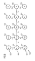
- TDRNN T ime D elay R ecurrent N eural N etwork
- the basic structure is a neural network deployed over three times t, t + 1, t + 2.
- It has an input layer which contains a predeterminable number of input neurons to which input quantities u t can be applied at predeterminable times t, ie time series values with predetermined time steps described below.
- the input neurons are connected via variable connections to neurons of a predefined number of hidden layers (represented by 3 hidden layers).
- neurons of a first hidden layer are connected to neurons of the first input layer.
- connection between the first hidden layer and the first input layer has weights contained in a first connection matrix B.
- the neurons of the first hidden layer are connected with their outputs to inputs of neurons of a second hidden layer according to a structure given by a second connection matrix A.
- the neurons of the second hidden layer are connected at their outputs to inputs of neurons of a third hidden layer according to a structure given by the second connection matrix A.
- the first hidden layer, the second hidden layer and the third hidden layer respectively "inner” states or “inner” system states s t , s t + 1 and s t + 2 of the dynamic process described at three consecutive times t, t + 1 and t + 2.
- the indications in the indices in the respective layers indicate in each case the time t, t + 1, t + 2, to which in each case the signals (u t ) which can be tapped or supplied at the outputs of the respective layer refer.
- An output layer 120 has two sub-output layers, a first sub-output layer and a second sub-output layer. Neurons of the first sub-output layer are connected to neurons of the first hidden layer according to a structure given by an output connection matrix C. Neurons of the second sub-output layer are also connected to neurons of the second hidden layer according to the structure given by the output connection matrix C.
- the output variables can be tapped for each time t + 1, t + 2 (y t + 1 , y t + 2 ).
- ECRNN Error Correction Recurrent Neural Networks
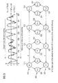
- Figure 3 shows a basic structure 300 with corresponding functional relationships of a CRCNN.
- Connections between the neurons of the CRCNN are weighted.
- the weights are summarized in parameter vectors v s , v t , v y .
- the CRCNN 300 is a neural network deployed over four times, t-1, t, t + 1 and t + 2 (see TDRNN, Figure 5 ).
- the document US 5,461,699 A discloses a system and method for predicting data based on a neural network. As input data of the neural network historical data and a statistical prediction of data are used. The statistical prediction is generated based on a statistical model that can use a regression technique or other statistical techniques.
- the invention is based on the problem to provide a method for determining a future system behavior of a dynamic system, which methods are not subject to the disadvantages of the known arrangements and methods, in particular their inaccuracies.
- the future system behavior is determined ("causality analysis"), the approximation for the future system behavior of the dynamic system being fed to the neural network structure as an input variable and an output variable the neural network structure represents the future system behavior.
- the neural network structure has two mutually coupled substructures, wherein a first neural substructure is adapted such that its first imaging behavior describes a forward behavior of the dynamic system and wherein a second neural substructure is adapted such that its second imaging behavior describes a reverse behavior of the dynamic system ,
- the invention provides a connection of a similarity analysis ("similarity analysis”) with a Causality analysis using a neural network structure.
- the similarity analysis is used to determine an approximation of a future (expected) system behavior from a historical system behavior. Based on this approximation, the future system behavior is then determined or predicted, similar to a post-correction using the neural network structure.
- This two-stage or combined approach namely first an approximation determination by means of a similarity analysis with subsequent post-correction using a neural network structure, is particularly suitable for predicting the system behavior of so-called "human-controlled” systems (HCS).
- HCS human-controlled systems
- Such HCS are to be understood as meaning systems which have a controlling and / or planning intervention.
- HCS energy consumption, power consumption or gas consumption or corresponding energy consumption behavior.
- the energy or electricity / gas consumption depends on an offer and a demand from or for energy. Although an interaction between supply and demand is subject to market-mechanical (economic) laws and mechanisms. However, by planning and correspondingly providing supply quantities of energy in the interaction or in the market dynamics, i. into the system, to be intervened.
- neural network structures in the context of the causality analysis
- causality analysis is particularly suitable for an effect-cause analysis (causality analysis).
- Dynamic systems are usually referred to as cause-and-effect relationships (see comments on Fig.2 , Relationships (1) to (3)) which can be mapped by the neuronal structures known from [1], [2] or [5].
- cause-and-effect relationships are expressed in these neuronal structures in that a flow of information generated in these neuronal structures is directed forward in time, ie from the past to the future. Such is called forward behavior.
- causes in input quantities u t at previous times (t-2), (t-1), ... lead to (noticeable) effects in output quantities y t at the instant (t or t + 1).
- the input quantities are ch u t imaged by the neural cause-effect structure on the output quantities y t .
- This "forward-looking" flow of information is particularly suitable for taking market-mechanical influence into account.
- This (effect-cause) extension structure or effect-cause structure generates a time-backwards information flow, ie an information flow directed from the future into the past. This is called reverse behavior. Effects in output quantities y t at the time (t) "lead” or have their causes in input quantities u t at the instant (t-1), (t-2), .... In this case, the cause-effect Structure output quantities y t (as input variables of the extension structure) are mapped to the input quantities u t (as output variables of the extension structure).
- This "backward-looking" information flow is particularly suitable for taking into account the planning and / or controlling influence.
- the invention is particularly suitable for predicting the future system behavior of the dynamic system. This prognosis can be derived from the determined future system behavior.
- the computer program with program code means is adapted to all steps according to the inventive method when the program is run on a computer.
- the computer program product with program code means stored on a machine-readable carrier is set up to perform all the steps according to the inventive method when the program is executed on a computer.
- the software solutions described can also be realized distributed or distributed, i. that parts of the computer program or parts of the computer program product - even as independent partial solutions - run on or run on different (distributed) computers or are stored on different storage media.
- the invention or each further described further development can be realized by a computer program product having a storage medium on which the computer program is stored with program code means, which executes the invention or development.
- the neural network structure has two partial structures coupled to one another.
- a first neural substructure is adapted in such a way that its first imaging behavior describes a forward behavior of the dynamic system.
- This first "forward" neural network structure which can be mapped by the neuronal structures known from [1], [2] or [5], is particularly suitable for determining cause-and-effect relationships (cf. Fig.2 , Relations (1) replicate to (3)) or to detect.
- This cause-and-effect relationship is expressed in this first neural substructure in that a flow of information generated in this first neural substructure is directed forward in time, ie from the past to the future. Such is called forward behavior.
- causes in input quantities u t at previous times (t-2), (t-1), ... lead to (noticeable) effects in output quantities y t at the instant (t or t + 1).
- the Input quantities u t are mapped to the output quantities y t by the neural cause-and-effect structure.
- the second neural substructure is adapted such that its second imaging behavior describes a reverse behavior of the dynamic system.
- This second "backward-facing" neural network structure which can be imaged by corresponding neuronal structures known from [1], [2] or [5], is suitable, in particular, for simulating or recognizing cause-effect relationships.
- This second "backward" neuronal substructure is thus particularly suitable for carrying out a cause-effect analysis in order to prepare a causal synthesis.
- the first "forward" neural substructure is particularly suitable for taking into account an influence of market mechanisms on the dynamic system.
- the second "backward" neural substructure is particularly suitable for taking into account a planning influence on the dynamic system.
- the neuronal structure of the first and second neuronal substructures can be referred to as Causal-Retro-Causal Neural Network.
- the first and / or the second neural substructure is / are a neural network deployed over several times, for example a TDRNN or neural networks deployed over a plurality of times, in which case or in which a temporal dimension of the described dynamic system is developed as a spatial dimension.
- first and / or second neural substructure may be / are configured as an Error Correction Recurrent Neural Network (ECRNN).
- ECRNN Error Correction Recurrent Neural Network
- the approximation for the future system behavior of the dynamic system can be determined such that the known system behavior is subdivided into sections of predefinable time lengths, such as a day or an hour. Associated section system behaviors are then determined for the sections.
- certain sections can be selected with their respective section system behaviors. Using these selected sections and the selected associated section system behavior can be approximated by taking into account a calendar effect.
- those sections are selected whose associated section system behavior has a significant behavior.
- system behavior may be interpolated and / or averaged between the selected section system behaviors and / or historical section system behavior inserted.
- the invention is used to predict energy consumption, in particular consumption of a gas quantity. Accordingly, the invention can also be used for a power consumption forecast.
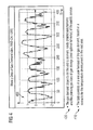
- Figure 4 shows a question 410 from an economic environment, which is solved by the procedure described in the context of the following embodiment of the invention.
- Figure 4 shows by way of example for a power consumption history a historical history 400 of an energy / gas consumption based on weekly consumption data for a period 01/92 - 10/99.
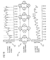
- 1a and 1b shows show a procedure used for the energy consumption forecast 2001.
- 1a shows a first step of the procedure, a similarity analysis (approximation step).
- 1b shows shows a second step of the procedure, a causality analysis (post-correction).
- a result of the first step is at the same time the output or input quantity for the second step.
- a historical, known energy consumption history in this case the energy consumption for the year 2000 111, is subdivided into periods of one day, so-called daily slices.
- significant energy consumption patterns 120, 121 which may consist of one or more contiguous daily slices, are selected from the historical energy consumption history 2000.
- Significant energy consumption patterns 120, 121 may be patterns that are exceptional in their shape, such as energy consumption peaks. Also significant are energy consumption patterns on significant days such as holidays (Christmas, Easter) or holidays.
- Such energy consumption patterns thus selected are to be prognosticated based on the corresponding day slices taking into account a calendar effect 2001 or into the period to be forecast 2001 or 130, 131.
- the result of this first step, the similarity analysis 110, is an approximation of the projected energy consumption history for 2001 112.
- Step 2 Causality analysis (Fig. 1b, 150)
- the causality analysis 150 is performed using a neural network structure called a causal retro causal neural network (CRC NN) 151 and 300 ( Figure 3 ), carried out.
- CRC NN causal retro causal neural network
- Figure 3 shows a basic structure 300 with corresponding functional relationships of a CRCNN.
- Connections between the neurons of the CRCNN are weighted.
- the weights are summarized in parameter vectors v s , v t , v y .
- the CRCNN 300 is a neural network deployed over four times, t-1, t, t + 1 and t + 2 (see TDRNN, Figure 5 ).
- the input quantity u t (301-304) is the result of the similarity analysis from the first stage (110), ie the approximated course of the predicted energy consumption 112, 152 determined in the first stage.
- the output quantity y t (341-344) is the desired result of the second-level causality analysis (150), ie the post-corrected course of the predicted energy consumption determined in the second stage 153.
Description
Die Erfindung betrifft ein Verfahren sowie ein Computerprogramm mit Programmcode-Mitteln und ein Computerprogramm-Produkt zur Ermittlung eines zukünftigen Systemverhaltens eines dynamischen Systems.The invention relates to a method and a computer program with program code means and to a computer program product for determining a future system behavior of a dynamic system.
Aus [1] ist es bekannt, zur Beschreibung und Modellierung eines dynamischen Systems bzw. eines dynamischen Prozesses und dessen Prozessverhaltens eine neuronale Struktur, beispielsweise ein neuronales Netz, einzusetzen.From [1] it is known to use a neural structure, for example a neural network, for the description and modeling of a dynamic system or a dynamic process and its process behavior.
Allgemein wird ein dynamisches System bzw. ein dynamischer Prozess durch eine Zustandsübergangsbeschreibung, die für einen Beobachter des dynamischen Prozesses nicht sichtbar ist, und eine Ausgangsgleichung, die beobachtbare Größen des technischen dynamischen Prozesses beschreibt, beschrieben.Generally, a dynamic system or process is described by a state transition description not visible to an observer of the dynamic process and an output equation describing observable quantities of the engineering dynamic process.
Ein solches Prozessverhalten eines dynamischen Prozesses ist in
Der dynamische Prozess 200 bzw. ein dynamisches System 200, in dem der dynamische Prozess abläuft, unterliegt dem Einfluss einer externen Eingangsgröße u vorgebbarer Dimension, wobei eine Eingangsgröße ut zu einem Zeitpunkt t mit ut bezeichnet wird: 
wobei mit 1 eine natürliche Zahl bezeichnet wird.The
where 1 is a natural number.
Die Eingangsgröße ut zu einem Zeitpunkt t verursacht eine Veränderung des dynamischen Prozesses.The input u t at a time t causes a change in the dynamic process.
Ein innerer Zustand st (st ∈ ![]()
![]()
In Abhängigkeit vom inneren Zustand st und der Eingangsgröße ut wird ein Zustandsübergang des inneren Zustandes st des dynamischen Prozesses verursacht und der Zustand des dynamischen Prozesses geht über in einen Folgezustand st+1 zu einem folgenden Zeitpunkt t+1.Depending on the internal state s t and the input quantity u t , a state transition of the internal state s t of the dynamic process is caused and the state of the dynamic process changes to a subsequent state s t + 1 at a subsequent instant t + 1.
Dabei gilt: 
wobei mit f(.) eine allgemeine Abbildungsvorschrift bezeichnet wird.Where:
where f (.) denotes a general mapping rule.
Eine von einem Beobachter des dynamischen Systems 200 beobachtbare Ausgangsgröße yt zu einem Zeitpunkt t hängt ab von der Eingangsgröße ut sowie dem inneren Zustand st.An output variable y t observable by an observer of the
Die Ausgangsgröße yt (yt ∈ ![]()
![]()
Die Abhängigkeit der Ausgangsgröße yt von der Eingangsgröße ut und dem inneren Zustand st des dynamischen Prozesses ist durch folgende allgemeine Vorschrift gegeben: ![]()
wobei mit g(.) eine allgemeine Abbildungsvorschrift bezeichnet wird.The dependence of the output variable y t on the input variable u t and the internal state s t of the dynamic process is given by the following general rule: ![]()
where g (.) denotes a general mapping rule.
Zur Beschreibung des dynamischen Systems 200 wird in [1] eine neuronale Struktur aus miteinander verbundenen Rechenelemente in Form eines neuronalen Netzes miteinander verbundener Neuronen eingesetzt. Die Verbindungen zwischen den Neuronen des neuronalen Netzes sind gewichtet. Die Gewichte des neuronalen Netzes sind in einem Parametervektor v zusammengefasst.For description of the
Somit hängt ein innerer Zustand eines dynamischen Systems, welches einem dynamischen Prozess unterliegt, gemäß folgender Vorschrift von der Eingangsgröße ut und dem inneren Zustand des vorangegangenen Zeitpunktes st und dem Parametervektor v ab: ![]()
wobei mit NN(.) eine durch das neuronale Netz vorgegebene Abbildungsvorschrift bezeichnet wird.Thus, an internal state of a dynamic system, which is subject to a dynamic process, depends on the input quantity u t and the internal state of the preceding time point s t and the parameter vector v according to the following rule: ![]()
where NN (.) denotes a mapping rule given by the neural network.
Diese Beschreibung des dynamischen Systems 200 gemäß Beziehung (3) wird auch als "Forecast Approach" bezeichnet.This description of
Alternativ dazu lässt sich das dynamische System auch durch: ![]()
mit ![]()
beschreiben, was als "Consistency Approach" bezeichnet wird. "Forecast Approach" und "Consistency Approach" führen zu geringfügigen strukturellen Unterschieden in den jeweiligen Netzstrukturen, sind aber gleichwertige, alternativ verwendbare Beschreibungsformen für dynamische Systeme.Alternatively, the dynamic system can also be: ![]()
With ![]()
describe what is called a "consistency approach". "Forecast Approach" and "Consistency Approach" lead to minor structural differences in the respective network structures, but are equivalent, alternatively usable forms of description for dynamic systems.
Aus [2] ist eine weitere neuronale Struktur zur Beschreibung des dynamischen Systems 200, ein als Time Delay Recurrent Neural Network (TDRNN) bezeichnetes neuronales Netz, bekannt. Das bekannte TDRNN ist in
Das in
Eingangs-Rechenelemente, d.h. Eingangsneuronen, sind über variable Verbindungen mit Neuronen einer vorgebbaren Anzahl versteckter Schichten 505 (dargestellt 5 verdeckte Schichten) verbunden.Input computation elements, i. Input neurons are connected via variable connections to neurons of a predefined number of hidden layers 505 (represented by 5 hidden layers).
Dabei sind Neuronen einer ersten 531, einer zweiten 532, einer dritten 533, einer vierten 534 und einer fünften 535 versteckten Schicht jeweils mit Neuronen der ersten 521, der zweiten 522, der dritten 523, der vierten 524 und der fünften 525 Teileingangsschicht verbunden.Here, neurons of a first 531, a
Die Verbindungen zwischen der ersten 531, der zweiten 532, der dritten 533, der vierten 534 und der fünften 535 versteckten Schicht mit jeweils der ersten 521, der zweiten 522, der dritten 523, der vierten 524 und der fünften 525 Teileingangsschicht sind jeweils gleich. Die Gewichte aller Verbindungen sind jeweils in einer ersten Verbindungsmatrix B1 enthalten.The connections between the first 531, the
Ferner sind die Neuronen der ersten versteckten Schicht 531 mit ihren Ausgängen mit Eingängen von Neuronen der zweiten versteckten Schicht 532 gemäß einer durch eine zweite Verbindungsmatrix A1 gegebene Struktur verbunden. Die Neuronen der zweiten versteckten Schicht 532 sind mit ihren Ausgängen mit Eingängen von Neuronen der dritten versteckten Schicht 533 gemäß einer durch die zweite Verbindungsmatrix A1 gegebene Struktur verbunden. Die Neuronen der dritten versteckten Schicht 533 sind mit ihren Ausgängen mit Eingängen von Neuronen der vierten versteckten Schicht 534 gemäß einer durch die zweite Verbindungsmatrix A1 gegebene Struktur verbunden. Die Neuronen der vierten versteckten Schicht 534 sind mit ihren Ausgängen mit Eingängen von Neuronen der fünften versteckten Schicht 535 gemäß einer durch die zweite Verbindungsmatrix A1 gegebene Struktur verbunden.Further, the neurons of the first
In den versteckten Schichten, der ersten versteckten Schicht 531, der zweiten versteckten Schicht 532, der dritten versteckten Schicht 533, der vierten versteckten Schicht 534 und der fünften versteckten Schicht 535 werden jeweils "innere" Zustände oder "innere" Systemzustände st-4, st-3, st-2, st-1, und st eines durch das TDRNN beschriebenen dynamischen Prozesses an fünf aufeinanderfolgenden Zeitpunkten t-4, t-3, t-2, t-1 und t repräsentiert.In the hidden layers, the first
Die Angaben in den Indizes in den jeweiligen Schichten geben jeweils den Zeitpunkt t-4, t-3, t-2, t-1 und t an, auf die sich jeweils die an den Ausgängen der jeweiligen Schicht abgreifbaren bzw. zuführbaren Signale beziehen (ut-4, ut-3, ut-2, ut-1, ut).The indications in the indices in the respective layers indicate in each case the time t-4, t-3, t-2, t-1 and t, to which in each case the signals which can be tapped or supplied at the outputs of the respective layer relate ( u t-4 , u t-3 , u t-2 , u t-1 , u t ).
Eine Ausgangsschicht 520 weist fünf Teilausgangsschichten, eine erste Teilausgangsschicht 541, eine zweite Teilausgangsschicht 542, eine dritte Teilausgangsschicht 543, eine vierte Teilausgangsschicht 544 sowie eine fünfte Teilausgangsschicht 545 auf. Neuronen der ersten Teilausgangsschicht 541 sind gemäß einer durch eine Ausgangs-Verbindungsmatrix C1 gegebenen Struktur mit Neuronen der ersten versteckten Schicht 531 verbunden. Neuronen der zweiten Teilausgangsschicht 542 sind ebenfalls gemäß der durch die Ausgangs-Verbindungsmatrix C1 gegebenen Struktur mit Neuronen der zweiten versteckten Schicht 532 verbunden. Neuronen der dritten Teilausgangsschicht 543 sind gemäß der Ausgangs-Verbindungsmatrix C1 mit Neuronen der dritten versteckten Schicht 533 verbunden. Neuronen der vierten Teilausgangsschicht 544 sind gemäß der Ausgangs-Verbindungsmatrix C1 mit Neuronen der vierten versteckten Schicht 534 verbunden. Neuronen der fünften Teilausgangsschicht 545 sind gemäß der Ausgangs-Verbindungsmatrix C1 mit Neuronen der fünften versteckten Schicht 535 verbunden. An den Neuronen der Teilausgangsschichten 541, 542, 543, 544 und 545 sind die Ausgangsgrößen für jeweils einen Zeitpunkt t-4, t-3, t-2, t-1, t abgreifbar (yt-4, yt-3, yt-2, yt-1, yt).An
Der Grundsatz, dass äquivalente Verbindungsmatrizen in einem neuronalen Netz zu einem jeweiligen Zeitpunkt die gleichen Werte aufweisen, wird als Prinzip der sogenannten geteilten Gewichtswerte (Shared Weights) bezeichnet.The principle that equivalent connection matrices in a neural network have the same values at a particular time is called a principle of so-called shared weights.
Die aus [2] bekannte und als Time Delay Recurrent Neural Network (TDRNN) bezeichnete Anordnung wird in einer Trainingsphase derart trainiert, dass zu einer Eingangsgröße ut jeweils eine Zielgröße ![]()
![]()
Dabei weisen zeitlich aufeinanderfolgende Tupel ![]()
![]()
![]()
![]()
Mit dem Trainingsdatensatz wird das TDRNN trainiert. Eine Übersicht über verschiedene Trainingsverfahren ist ebenfalls in [1] und [4] zu finden.The training data set is used to train the TDRNN. An overview of different training methods can also be found in [1] and [4].
Es.ist an dieser Stelle zu betonen, dass lediglich die Ausgangsgrößen yt-4, yt-3, ..., yt zu Zeitpunkten t-4, t-3, ..., t des dynamischen Systems 200 erkennbar sind. Die "inneren" Systemzustände st-4, st-3, ..., st sind nicht beobachtbar.It should be emphasized at this point that only the output quantities y t-4 , y t-3 ,..., Y t can be recognized at times t-4, t-3,..., T of the
In der Trainingsphase wird üblicherweise folgende Kostenfunktion E minimiert: 
wobei mit T eine Anzahl berücksichtigter Zeitpunkte bezeichnet wird.In the training phase, the following cost function E is usually minimized:
where T denotes a number of considered times.
Aus [5] und [6] sind Weiterentwicklungen der aus [2] bekannten und als Time Delay Recurrent Neural Network (TDRNN) bezeichneten neuronalen Struktur bekannt.From [5] and [6] further developments of the known from [2] and as T ime D elay R ecurrent N eural N etwork (TDRNN) designated neural structure known.
Die Weiterentwicklungen aus [5] sind insbesondere geeignet zur Ermittlung zukünftiger Zustände eines dynamischen Prozesses, was als "overshooting" bezeichnet wird.The further developments from [5] are particularly suitable for the determination of future states of a dynamic process, which is called "overshooting".
Die Grundstruktur ist ein über drei Zeitpunkte t, t+1, t+2 entfaltetes neuronales Netz.The basic structure is a neural network deployed over three times t, t + 1, t + 2.
Sie weist eine Eingangsschicht auf, die eine vorgebbare Anzahl von Eingangsneuronen enthält, denen Eingangsgrößen ut zu vorgebbaren Zeitpunkten t, d.h. im weiteren beschriebene Zeitreihenwerte mit vorgegebenen Zeitschritten, anlegbar sind.It has an input layer which contains a predeterminable number of input neurons to which input quantities u t can be applied at predeterminable times t, ie time series values with predetermined time steps described below.
Die Eingangsneuronen, sind über variable Verbindungen mit Neuronen einer vorgebbaren Anzahl versteckter Schichten (dargestellt 3 verdeckte Schichten) verbunden.The input neurons are connected via variable connections to neurons of a predefined number of hidden layers (represented by 3 hidden layers).
Dabei sind Neuronen einer ersten versteckten Schicht mit Neuronen der ersten Eingangsschicht verbunden.In this case, neurons of a first hidden layer are connected to neurons of the first input layer.
Die Verbindung zwischen der ersten versteckten Schicht mit der ersten Eingangsschicht weist Gewichte auf, die in einer ersten Verbindungsmatrix B enthalten sind.The connection between the first hidden layer and the first input layer has weights contained in a first connection matrix B.
Ferner sind die Neuronen der ersten versteckten Schicht mit ihren Ausgängen mit Eingängen von Neuronen einer zweiten versteckten Schicht gemäß einer durch eine zweite Verbindungsmatrix A gegebene Struktur verbunden. Die Neuronen der zweiten versteckten Schicht sind mit ihren Ausgängen mit Eingängen von Neuronen einer dritten versteckten Schicht gemäß einer durch die zweite Verbindungsmatrix A gegebene Struktur verbunden.Furthermore, the neurons of the first hidden layer are connected with their outputs to inputs of neurons of a second hidden layer according to a structure given by a second connection matrix A. The neurons of the second hidden layer are connected at their outputs to inputs of neurons of a third hidden layer according to a structure given by the second connection matrix A.
In den versteckten Schichten, der ersten versteckten Schicht, der zweiten versteckten Schicht und der dritten versteckten Schicht werden jeweils "innere" Zustände oder "innere" Systemzustände st, st+1 und st+2 des beschriebenen dynamischen Prozesses an drei aufeinanderfolgenden Zeitpunkten t, t+1 und t+2 repräsentiert.In the hidden layers, the first hidden layer, the second hidden layer and the third hidden layer respectively "inner" states or "inner" system states s t , s t + 1 and s t + 2 of the dynamic process described at three consecutive times t, t + 1 and t + 2.
Die Angaben in den Indizes in den jeweiligen Schichten geben jeweils den Zeitpunkt t, t+1, t+2 an, auf die sich jeweils die an den Ausgängen der jeweiligen Schicht abgreifbaren bzw. zuführbaren Signale (ut) beziehen.The indications in the indices in the respective layers indicate in each case the time t, t + 1, t + 2, to which in each case the signals (u t ) which can be tapped or supplied at the outputs of the respective layer refer.
Eine Ausgangsschicht 120 weist zwei Teilausgangsschichten, eine erste Teilausgangsschicht und eine zweite Teilausgangsschicht, auf. Neuronen der ersten Teilausgangsschicht sind gemäß einer durch eine Ausgangs-Verbindungsmatrix C gegebenen Struktur mit Neuronen der ersten versteckten Schicht verbunden. Neuronen der zweiten Teilausgangsschicht sind ebenfalls gemäß der durch die Ausgangs-Verbindungsmatrix C gegebenen Struktur mit Neuronen der zweiten versteckten Schicht verbunden.An
An den Neuronen der Teilausgangsschichten sind die Ausgangsgrößen für jeweils einen Zeitpunkt t+1, t+2 abgreifbar (yt+1, yt+2).At the neurons of the sub-output layers, the output variables can be tapped for each
Eine weitere Weiterentwicklung dieser Grundstruktur aus [5] ist in
Weiterentwicklungen der TDRNN-Struktur aus [6], sogenannte Error-Correction-Recurrent-Neural-Networks ECRNN), betreffen einen strukturell bedingten Fehler-Korrektur-Mechanismus, welcher als struktureller Bestandteil in eine neuronale Struktur integriert ist.
Aus [7] ist eine weitere neuronale Struktur zur Beschreibung des dynamischen Systems 200, ein als Causal-Retro-Causal Time Delay Recurrent Neural Network (kurz Causal-Retro-Causal Neural Network; CRCNN) bezeichnetes neuronales Netz, bekannt.From [7] is another neural structure for the description of the
Bei diesem CRCNN sind zwei neuronale Teilstrukturen 310, 320 miteinander gekoppelt. Dabei hängen ein erster innerer Teilzustand st (311 - 314) der ersten neuronalen Teilstruktur 310 und ein zweiter inneren Teilzustand rt (321 - 324) der zweiten neuronalen Teilstruktur 320 gemäß folgenden Vorschriften von der Eingangsgröße ut (301 - 304),dem ersten inneren Teilzustand st-1 (311 - 314),dem zweiten inneren Teilzustand rt+1 (321 - 324) sowie Parametervektoren vs, vt, vy ab: ![]()
![]()
![]()
![]()
![]()
![]()
Verbindungen zwischen den Neuronen des CRCNN sind gewichtet. Die Gewichte sind in Parametervektoren vs, vt, vy zusammengefasst.Connections between the neurons of the CRCNN are weighted. The weights are summarized in parameter vectors v s , v t , v y .
Das CRCNN 300 gemäß
Grundzüge eines über eine endliche Anzahl von Zeitpunkten entfaltetes Neuronalen Netzes sind in [2] und im obigen im Zusammenhang mit dem bekannten TDRNN (vgl.
In [3] ist ferner ein Überblick über Grundlagen neuronaler Netze und die Anwendungsmöglichkeiten neuronaler Netze im Bereich der Ökonomie zu finden.In [3] an overview of the basics of neural networks and the applications of neural networks in the field of economics can be found.
Die bekannten Anordnungen und Verfahren weisen insbesondere den Nachteil auf, dass durch sie ein zu beschreibendes dynamisches System nur unzureichend genau beschrieben und damit zukünftige Entwicklungen des Systems nur unzureichend genau prognostiziert werden können.In particular, the known arrangements and methods have the disadvantage that they do not adequately describe a dynamic system to be described, and therefore future developments of the system can only be predicted with insufficient accuracy.
Dies gilt insbesondere für dynamische Systeme, welche einem planerischen Einfluss unterliegen, d.h. dynamische Systeme, welche nicht nur rein marktgetrieben sind.This is especially true for dynamic systems which are subject to planning influence, i. E. dynamic systems, which are not just purely market-driven.
Das Dokument
Diese Aufgabe wird durch das Verfahren sowie durch das Computerprogramm mit Programmcode-Mitteln und das Computerprogramm-Produkt zur Ermittlung eines zukünftigen Systemverhaltens eines dynamischen Systems mit den Merkmalen gemäß dem jeweiligen unabhängigen Patentanspruch gelöst.This object is achieved by the method as well as by the computer program with program code means and the computer program product for determining a future system behavior of a dynamic system with the features according to the respective independent claim.
Bei dem Verfahren zur Ermittlung eines zukünftigen Systemverhaltens eines dynamischen Systems wird unter Verwendung eines bekannten Systemsverhaltens des dynamischen Systems durch einen Ähnlichkeitsvergleich bzw. Ähnlichkeitsanalyse eine Näherung für das zukünftige Systemverhalten ermittelt ("Similarity Analysis").In the method for determining a future system behavior of a dynamic system, using a known system behavior of the dynamic system by means of a similarity analysis or similarity analysis, an approximation for the future system behavior is determined ("similarity analysis").
Dann wird unter Verwendung der Näherung für das zukünftige Systemverhalten des dynamischen Systems und unter Verwendung einer neuronalen Netzstruktur das zukünftige Systemverhalten ermittelt ("Causality Analysis"), wobei die Näherung für das zukünftige Systemverhalten des dynamischen Systems der neuronalen Netzstruktur als Eingangsgröße zugeführt wird und eine Ausgangsgröße der neuronalen Netzstruktur das zukünftige Systemverhalten repräsentiert. Die neuronale Netzstruktur weist dabei zwei miteinander gekoppelte Teilstrukturen auf, wobei eine erste neuronale Teilstruktur derart angepasst ist, dass deren erstes Abbildungsverhalten ein Vorwärtsverhalten des dynamischen Systems beschreibt und wobei eine zweite neuronale Teilstruktur derart angepasst ist, dass deren zweites Abbildungsverhalten ein Rückwärtsverhalten des dynamischen Systems beschreibt.Then, using the approximation for the future system behavior of the dynamic system and using a neural network structure, the future system behavior is determined ("causality analysis"), the approximation for the future system behavior of the dynamic system being fed to the neural network structure as an input variable and an output variable the neural network structure represents the future system behavior. The neural network structure has two mutually coupled substructures, wherein a first neural substructure is adapted such that its first imaging behavior describes a forward behavior of the dynamic system and wherein a second neural substructure is adapted such that its second imaging behavior describes a reverse behavior of the dynamic system ,
Anschaulich gesehen stellt die Erfindung eine Verbindung einer Ähnlichkeitsanalyse ("Similarity Analysis") mit einer Kausalitätsanalyse ("Causality Analysis") unter Verwendung einer neuronalen Netzstruktur dar.Illustrated clearly, the invention provides a connection of a similarity analysis ("similarity analysis") with a Causality analysis using a neural network structure.
Dabei wird die Ähnlichkeitsanalyse dazu eingesetzt, um aus einem historischen Systemverhalten eine Näherung eines zukünftigen (zu erwartenden) Systemverhaltens zu ermitteln. Basierend auf dieser Näherung wird anschließend gleich einer Nachkorrektur unter Verwendung der neuronalen Netzstruktur das zukünftige Systemverhalten bestimmt bzw. prognostiziert.In this case, the similarity analysis is used to determine an approximation of a future (expected) system behavior from a historical system behavior. Based on this approximation, the future system behavior is then determined or predicted, similar to a post-correction using the neural network structure.
Diese zweistufige bzw. kombinierte Vorgehensweise, nämlich zuerst eine Näherungsermittlung durch eine Ähnlichkeitsanalyse mit anschließender Nachkorrektur unter Verwendung einer neuronalen Netzstruktur, ist insbesondere geeignet, um das Systemverhalten von sogenannten "Human Controlled" Systemen (HCS) zu prognostizieren.This two-stage or combined approach, namely first an approximation determination by means of a similarity analysis with subsequent post-correction using a neural network structure, is particularly suitable for predicting the system behavior of so-called "human-controlled" systems (HCS).
Unter solchen HCS sind solche Systeme zu verstehen, welche einem kontrollierenden und/oder planerisch eingreifenden Einfluss unterliegen.Such HCS are to be understood as meaning systems which have a controlling and / or planning intervention.
Beispiele für solche HCS sind ein Energieverbrauch, ein Stromverbrauch oder eine Gasverbrauch bzw. entsprechende E-nergieverbrauchsverhalten.Examples of such HCS are energy consumption, power consumption or gas consumption or corresponding energy consumption behavior.
Der Energie- bzw. Strom-/Gasverbrauch hängt dabei ab von einem Angebot und einer Nachfrage von bzw. nach Energie. Ein Zusammenspiel von Angebot und Nachfrage unterliegt zwar marktmechanischen (ökonomischen) Gesetzmäßigkeiten bzw. Mechanismen. Allerdings kann durch Planung und entsprechendes zur Verfügung stellen von Angebotsmengen an Energie in das Zusammenspiel bzw. in die Markdynamik, d.h. in das System, eingegriffen werden.The energy or electricity / gas consumption depends on an offer and a demand from or for energy. Although an interaction between supply and demand is subject to market-mechanical (economic) laws and mechanisms. However, by planning and correspondingly providing supply quantities of energy in the interaction or in the market dynamics, i. into the system, to be intervened.
Insbesondere sind bei der Erfindung solche neuronale Netzstrukturen (im Rahmen der Kausalitätsanalyse) anzuwenden, welche insbesondere für eine Wirkungs-Ursachenanalyse (Kausalitätsanalyse) geeignet sind.In particular, in the invention, such neural network structures (in the context of the causality analysis) are to be used, which are particularly suitable for an effect-cause analysis (causality analysis).
Dynamische Systeme werden üblicherweise als Ursache-Wirkungs-zusammenhänge (vgl. Ausführungen zu
Dieser "vorwärtsgerichtete" Informationsfluss ist insbesondere geeignet, um den marktmechanischen Einfluss zu berücksichtigen.This "forward-looking" flow of information is particularly suitable for taking market-mechanical influence into account.
Diese "eindimensionalen" (vorwärtsgerichteten) Strukturen für die Ursache-Wirkungs-Zusammenhänge können erweitert werden mit einer neuronalen Teilstruktur, welche eine Wirkungs-Ursachenanalyse durchführt und damit eine kausale Synthese vorbereitet.These "one-dimensional" (forward) structures for the cause-and-effect relationships can be extended with a neural substructure, which performs a cause-effect analysis and thus prepares a causal synthesis.
Bei dieser (Wirkungs-Ursache-)Erweiterungsstruktur bzw. Wirkungs-Ursache-Struktur wird ein zeitlich rückwärts gerichteter Informationsfluss, d.h. ein von der Zukunft in die Vergangenheit gerichteter Informationsfluss, erzeugt. Solches wird als Rückwärtsverhalten bezeichnet. Wirkungen in Ausgangsgrößen yt zum Zeitpunkt (t) "führen" bzw. haben ihre Ursachen in Eingangsgrößen ut zum Zeitpunkt (t-1), (t-2), .... Dabei werden in umgekehrter Weise zur Ursachen-Wirkungs-Struktur Ausgangsgrößen yt (als Eingangsgrößen der Erweiterungsstruktur) auf die Eingangsgrößen ut (als Ausgangsgrößen der Erweiterungsstruktur) abgebildet.This (effect-cause) extension structure or effect-cause structure generates a time-backwards information flow, ie an information flow directed from the future into the past. This is called reverse behavior. Effects in output quantities y t at the time (t) "lead" or have their causes in input quantities u t at the instant (t-1), (t-2), .... In this case, the cause-effect Structure output quantities y t (as input variables of the extension structure) are mapped to the input quantities u t (as output variables of the extension structure).
Dieser "rückwärtsgerichtete" Informationsfluss ist insbesondere geeignet, um den planerischen und/oder kontrollierenden Einfluss zu berücksichtigen.This "backward-looking" information flow is particularly suitable for taking into account the planning and / or controlling influence.
Die Erfindung ist insbesondere geeignet, zu einer Prognose des zukünftigen Systemverhaltens des dynamischen Systems. Diese Prognose kann abgeleitet werden aus dem ermittelten zukünftige Systemverhalten.The invention is particularly suitable for predicting the future system behavior of the dynamic system. This prognosis can be derived from the determined future system behavior.
Das Computerprogramm mit Programmcode-Mitteln ist eingerichtet, um alle Schritte gemäß dem erfindungsgemäßen Verfahren durchzuführen, wenn das Programm auf einem Computer ausgeführt wird.The computer program with program code means is adapted to all steps according to the inventive method when the program is run on a computer.
Das Computerprogramm-Produkt mit auf einem maschinenlesbaren Träger gespeicherten Programmcode-Mitteln ist eingerichtet, um alle Schritte gemäß dem erfindungsgemäßen Verfahren durchzuführen, wenn das Programm auf einem Computer ausgeführt wird.The computer program product with program code means stored on a machine-readable carrier is set up to perform all the steps according to the inventive method when the program is executed on a computer.
Die Anordnung sowie das Computerprogramm mit Programmcode-Mitteln, eingerichtet um alle Schritte gemäß dem erfinderischen Verfahren durchzuführen, wenn das Programm auf einem Computer ausgeführt wird, sowie das Computerprogramm-Produkt mit auf einem maschinenlesbaren Träger gespeicherten Programmcode-Mitteln, eingerichtet um alle Schritte gemäß dem erfinderischen Verfahren durchzuführen, wenn das Programm auf einem Computer ausgeführt wird, sind insbesondere geeignet zur Durchführung des erfindungsgemäßen Verfahrens oder einer seiner nachfolgend erläuterten Weiterbildungen.The arrangement as well as the computer program with program code means set up to carry out all the steps according to the inventive method when the program is run on a computer, and the computer program product with program code means stored on a machine-readable carrier, arranged at all steps according to the To carry out inventive method, when the program is executed on a computer, are particularly suitable for carrying out the method according to the invention or one of its developments explained below.
Dabei können die beschriebenen Softwarelösungen auch dezentral bzw. verteilt realisiert sein, d.h. dass Teile des Computerprogramms oder Teile des Computerprogramm-Produkts - auch als eigenständige Teillösungen - auf verschiedenen (verteilten) Computern ablaufen bzw. von diesen ausgeführt werden oder auf verschiedenen Speichermedien gespeichert sind.In this case, the software solutions described can also be realized distributed or distributed, i. that parts of the computer program or parts of the computer program product - even as independent partial solutions - run on or run on different (distributed) computers or are stored on different storage media.
Bevorzugte Weiterbildungen der Erfindung ergeben sich aus den abhängigen Ansprüchen.Preferred developments of the invention will become apparent from the dependent claims.
Die im weiteren beschriebenen Weiterbildungen beziehen sich sowohl auf das Verfahren als auch das Computerprogramm mit Programmcode-Mitteln und das Computerprogramm-Produkt.The developments described below relate both to the method and the computer program with program code means and the computer program product.
Die Erfindung und die im weiteren beschriebenen Weiterbildungen können sowohl in Software als auch in Hardware, bei spielsweise unter Verwendung einer speziellen elektrischen Schaltung, realisiert werden.The invention and the further developments described in both software and in hardware, in For example, using a special electrical circuit can be realized.
Ferner ist eine Realisierung der Erfindung oder einer im weiteren beschriebenen Weiterbildung möglich durch ein computerlesbares Speichermedium, auf welchem das Computerprogramm mit Programmcode-Mitteln gespeichert ist, welches die Erfindung oder Weiterbildung ausführt.Furthermore, an implementation of the invention or a development described further is possible by a computer-readable storage medium on which the computer program is stored with program code means, which executes the invention or development.
Auch kann die Erfindung oder jede im weiteren beschriebene Weiterbildung durch ein Computerprogrammerzeugnis realisiert sein, welches ein Speichermedium aufweist, auf welchem das Computerprogramm mit Programmcode-Mitteln gespeichert ist, welches die Erfindung oder Weiterbildung ausführt.Also, the invention or each further described further development can be realized by a computer program product having a storage medium on which the computer program is stored with program code means, which executes the invention or development.
Bei eine Weiterbildung weist die neuronale Netzstruktur zwei miteinander gekoppelte Teilstrukturen auf.In a further development, the neural network structure has two partial structures coupled to one another.
Eine erste neuronale Teilstruktur ist derart angepasst, dass deren erstes Abbildungsverhalten ein Vorwärtsverhalten des dynamischen Systems beschreibt.A first neural substructure is adapted in such a way that its first imaging behavior describes a forward behavior of the dynamic system.
Diese erste "vorwärtsgerichtete" neuronale Netzstruktur, welche durch die aus [1],[2] oder [5] bekannten neuronalen Strukturen abgebildet werden kann, ist insbesondere geeignet, um Ursache-Wirkungszusammenhänge (vgl. Ausführungen zu
Dieser Ursache-Wirkungszusammenhang findet in dieser ersten neuronalen Teilstruktur darin Ausdruck, dass ein bei dieser ersten neuronalen Teilstruktur erzeugter Informationsfluss zeitlich vorwärts, d.h. von der Vergangenheit in die Zukunft, gerichtet ist. Solches wird als Vorwärtsverhalten bezeichnet. Ursachen in Eingangsgrößen ut zu vorangegangenen Zeitpunkten (t-2), (t-1), ... führen zu (bemerkbaren) Wirkungen in Ausgangsgrößen yt zum Zeitpunkt (t bzw. t+1). Dabei werden die Eingangsgrößen ut durch die neuronale Ursachen-Wirkungs-Struktur auf die Ausgangsgrößen yt abgebildet.This cause-and-effect relationship is expressed in this first neural substructure in that a flow of information generated in this first neural substructure is directed forward in time, ie from the past to the future. Such is called forward behavior. Causes in input quantities u t at previous times (t-2), (t-1), ... lead to (noticeable) effects in output quantities y t at the instant (t or t + 1). Here are the Input quantities u t are mapped to the output quantities y t by the neural cause-and-effect structure.
Die zweite neuronale Teilstruktur ist derart angepasst, dass deren zweites Abbildungsverhalten ein Rückwärtsverhalten des dynamischen Systems beschreibt.The second neural substructure is adapted such that its second imaging behavior describes a reverse behavior of the dynamic system.
Diese zweite "rückwärtsgerichtete" neuronale Netzstruktur, welche durch entsprechende aus [1],[2] oder [5] bekannten neuronalen Strukturen abgebildet werden kann, ist insbesondere geeignet, um Wirkungs-Ursachenzusammenhänge nachzubilden bzw. zu erkennen.This second "backward-facing" neural network structure, which can be imaged by corresponding neuronal structures known from [1], [2] or [5], is suitable, in particular, for simulating or recognizing cause-effect relationships.
Diese zweite "rückwärtsgerichtete" neuronale Teilstruktur ist damit insbesondere geeignet für die Durchführung einer Wirkungs-Ursachenanalyse, um damit eine kausale Synthese vorzubereiten.This second "backward" neuronal substructure is thus particularly suitable for carrying out a cause-effect analysis in order to prepare a causal synthesis.
Bei dieser (Wirkungs-Ursache-)Teilstruktur wird ein zeitlich rückwärts gerichteter Informationsfluss, d.h. ein von der Zukunft in die Vergangenheit gerichteter Informationsfluss, erzeugt. Solches wird als Rückwärtsverhalten bezeichnet. Wirkungen in Ausgangsgrößen yt zum Zeitpunkt (t) "führen" bzw. haben ihre Ursachen in Eingangsgrößen ut zum Zeitpunkt (t-1), (t-2), .... Dabei werden in umgekehrter Weise zur Ursachen-Wirkungs-Struktur Ausgangsgrößen yt (als Eingangsgrößen der zweiten neuronalen Teilstruktur) auf die Eingangsgrößen ut (als Ausgangsgrößen der zweiten neuronalen Teilstruktur) abgebildet.In this (cause-and-effect) substructure, a backward information flow is generated, ie an information flow directed from the future into the past. This is called reverse behavior. Effects in output quantities y t at the time (t) "lead" or have their causes in input quantities u t at the instant (t-1), (t-2), .... In this case, the cause-effect Structure output variables y t (as input variables of the second neural substructure) to the input quantities u t (as output variables of the second neural substructure) mapped.
Ferner ist die erste "vorwärtsgerichtete" neuronale Teilstruktur insbesondere geeignet, einen Einfluss von Marktmechanismen auf das dynamische System zu berücksichtigen.Furthermore, the first "forward" neural substructure is particularly suitable for taking into account an influence of market mechanisms on the dynamic system.
Die zweite "rückwärtsgerichtete" neuronale Teilstruktur ist insbesondere dazu geeignet, einen planerische Einfluss auf das dynamische System zu berücksichtigen.The second "backward" neural substructure is particularly suitable for taking into account a planning influence on the dynamic system.
Entsprechend diesem "vorwärtsgerichteten" Ursache-Wirkungszusammenhang (Kausalität) und dem "rückwärtsgerichteten" Wirkungs-Ursachezusammenhang (Retrokausalität) kann die neuronale Struktur aus erster und zweiter neuronalen Teilstruktur als Causal-Retro-Causal Neural Network bezeichnet werden.According to this "forward-looking" cause-effect relationship (causality) and the "retrospective" cause-effect relationship (retrocausality), the neuronal structure of the first and second neuronal substructures can be referred to as Causal-Retro-Causal Neural Network.
Bei einer Weiterbildung ist bzw. sind die erste und/oder die zweite neuronale Teilstruktur ein über mehrere Zeitpunkte entfaltetes neuronales Netz, beispielsweise eine TDRNN, bzw. über mehrere Zeitpunkte entfaltete neuronale Netze, bei welchem bzw. bei welchen eine zeitliche Dimension des beschriebenen dynamischen Systems als räumliche Dimension entwickelt wird.In a development, the first and / or the second neural substructure is / are a neural network deployed over several times, for example a TDRNN or neural networks deployed over a plurality of times, in which case or in which a temporal dimension of the described dynamic system is developed as a spatial dimension.
Darüber hinaus kann es sinnvoll sein, dass die erste und/oder zweite neuronale Teilstruktur als Error-Correction-Recurrent-Neural-Network (ECRNN) ausgestalten ist/sind. Grundlagen solcher ECRNN sind in [6] beschrieben und können entsprechend in die neuronalen Teilstrukturen eingebaut werden.In addition, it may be useful for the first and / or second neural substructure to be / are configured as an Error Correction Recurrent Neural Network (ECRNN). Bases of such ECRNN are described in [6] and can be incorporated into the neural substructures.
Bei einer Ausgestaltung ist vorgesehen, das bekannte Systemsverhalten des dynamischen Systems unter Verwendung historischer Systemdaten zu ermitteln.In one embodiment, it is provided to determine the known system behavior of the dynamic system using historical system data.
Die Näherung für das zukünftige Systemverhalten des dynamischen Systems kann derart ermittelt werden, dass das bekannte Systemverhalten in Abschnitte vorgebbarer Zeitlängen, wie ein Tag oder eine Stunde, unterteilt wird. Zu den Abschnitten werden dann zugehörige Abschnittssystemverhalten ermittelt.The approximation for the future system behavior of the dynamic system can be determined such that the known system behavior is subdivided into sections of predefinable time lengths, such as a day or an hour. Associated section system behaviors are then determined for the sections.
Aus den Abschnitten können bestimmte Abschnitte mit den jeweiligen zugehörigen Abschnittssystemverhalten ausgewählt werden. Unter Verwendung dieser ausgewählten Abschnitte und der ausgewählten zugehörigen Abschnittssystemverhalten kann bei Berücksichtigung eines kalendarischen Effekts die Näherung ermittelt werden.From the sections, certain sections can be selected with their respective section system behaviors. Using these selected sections and the selected associated section system behavior can be approximated by taking into account a calendar effect.
In einer Ausgestaltung werden solche Abschnitte ausgewählt, deren zugehöriges Abschnittssystemverhalten ein signifikantes Verhalten aufweist.In one embodiment, those sections are selected whose associated section system behavior has a significant behavior.
Bei der Ermittlung der Näherung für das zukünftige Systemverhalten des dynamischen Systems unter Verwendung der ausgewählten Abschnittssystemverhalten kann ein Systemverhalten zwischen den ausgewählten Abschnittssystemverhalten interpoliert und/oder gemittelt und/oder historische Abschnittssystemverhalten eingefügt werden/wird.In determining the approximation of the future system behavior of the dynamic system using the selected section system behaviors, system behavior may be interpolated and / or averaged between the selected section system behaviors and / or historical section system behavior inserted.
In einer Weiterbildung wird die Erfindung eingesetzt zu einer Prognose eines Energieverbrauchs, insbesondere eines Verbrauchs von einer Gasmenge. Entsprechend kann die Erfindung auch für eine Stromverbrauchsprognose eingesetzt werden.In a development, the invention is used to predict energy consumption, in particular consumption of a gas quantity. Accordingly, the invention can also be used for a power consumption forecast.
Andere Einsatzszenarien sind vorstellbar, wie bei ökonomischen Systemen (Finanzdienstleistungen, Banken, Versicherungen) oder Industriesystemen (Produktionssysteme, Industrieanlagen, Logistiksysteme).Other application scenarios are conceivable, such as economic systems (financial services, banks, insurance companies) or industrial systems (production systems, industrial plants, logistics systems).
Ein Ausführungsbeispiel der Erfindung ist in Figuren dargestellt und wird im weiteren näher erläutert.An embodiment of the invention is illustrated in figures and will be explained in more detail below.
Es zeigen
- Figuren 1a und 1b
- Skizze einer zweistufigen Vorgehensweise bei einer Energieprognose (1a: erste Stufe: Ähnlichkeitsanalyse; 1b: zweite Stufe: Kausalitätsanalyse) gemäß einem Ausführungsbeispiel;
Figur 2- eine Skizze einer allgemeinen Beschreibung eines dynamischen Systems;
Figur 3- eine Skizze eines CRCNN mit grundlegenden funktionalen Beziehungen;
Figur 4- eine Skizze, welche einen historischen Verlauf eines Energie-/Gasverbrauchs zeigt (Wochendaten für 01/92 - 10/99);
- Figur 5
- eine Skizze einer Anordnung eines TDRNN, welche mit endlich vielen Zuständen über die Zeit entfaltet ist;
- Figur 6
- eine Skizze einer zum "overshooting" geeigneten Weiterbildung eines TDRNN;
- Figur 7
- eine Skizze eines ECRNN mit grundlegenden funktionalen Beziehungen.
- FIGS. 1a and 1b
- Sketch of a two-step procedure in an energy forecast (1a: first stage: similarity analysis, 1b: second stage: causality analysis) according to an embodiment;
- FIG. 2
- a sketch of a general description of a dynamic system;
- FIG. 3
- a sketch of a CRCNN with basic functional relationships;
- FIG. 4
- a sketch showing a historical history of an energy / gas consumption (weekly data for 01/92 - 10/99);
- FIG. 5
- a sketch of an arrangement of a TDRNN, which is unfolded with finitely many states over time;
- FIG. 6
- a sketch of a "overshooting" suitable training of a TDRNN;
- FIG. 7
- a sketch of an ECRNN with basic functional relationships.
Gesucht wird eine Prognose für einen Energieverbrauch bzw. Gasverbrauch für ein zukünftiges Jahr 2001, basierend auf ein vorgegebenes Szenario einer Temperaturentwicklung für den Prognosezeitraum.We are looking for a forecast for energy consumption or gas consumption for a
Der Gasverbrauch ist dabei im Allgemeinen abhängig von einer Nachfrage von Kunden (Marktmechanik) und einer Planungsstrategie (Kostenminimierung) für eine Gasbevorratung von Versorgungsunternehmen (planerischer Einfluss) 420. Vorgehensweise (Fiq.1a und Fiq.1b) Gas consumption is generally dependent on a demand from customers (market mechanics) and a planning strategy (cost minimization) for utility gas storage (planning influence) 420. Procedure (Fiq.1a and Fiq.1b)
Bei der Ähnlichkeitsanalyse 110 wird ein historischer, bekannter Energieverbrauchsverlauf, in diesem Fall der Energieverbrauch für das Jahr 2000 111, in Zeitabschnitte von jeweils einem Tag, sogenannte Tagesscheiben, unterteilt.In the
Weiterer werden signifikante Energieverbrauchsmuster 120, 121, welche aus einer oder mehreren zusammenhängenden Tagesscheiben bestehen können, aus dem historischen Energieverbrauchsverlauf 2000 ausgewählt.Furthermore, significant
Signifikante Energieverbrauchsmuster 120, 121 können dabei Muster sein, die in ihrer Verlaufsform außergewöhnlich, wie Energieverbrauchsspitzen, sind. Auch signifikant sind Energieverbrauchsmuster an signifikanten Tagen, wie Feiertage (Weihnachten, Ostern) oder Ferienbeginn.Significant
Solche derart ausgewählten Energieverbrauchsmuster werden basierend auf den entsprechenden Tagesscheiben unter Berücksichtigung eines kalendarischen Effekts in das zu prognosti zierende Jahr 2001 bzw. in den zu prognostizierenden Zeitraum 2001 übertragen bzw. projiziert 130, 131.Such energy consumption patterns thus selected are to be prognosticated based on the corresponding day slices taking into account a
Unter dem kalendarischen Effekt ist dabei zu verstehen, dass beispielsweise eine "Tagesscheibe" bzw. der Energieverbrauchsverlauf an Ostern 2000 (historisch) als prognostizierte, genäherte "Tagesscheibe" bzw. Energieverbrauchsverlauf für Ostern 2001 (Näherungsprognose) angenommen wird (trotz Datumsunterschied zwischen Ostern 2000 und 2001).Under the calendar effect is to be understood that, for example, a "daily slice" or the energy consumption at Easter 2000 (historical) as predicted, approximated "daily slice" or energy consumption for Easter 2001 (approximate forecast) is adopted (despite date difference between
Entsprechend wird mit allen ausgewählten signifikanten Energieverbrauchsmuster 120, 121 aus 2000 bei Übertragung in 2001 verfahren 130, 131.Correspondingly, all selected significant
Noch im genäherten, prognostizierten Energieverbrauchsverlauf von 2001 auftretende (Verlaufs-)Lücken 140 können nun geschlossen werden.Even in the approximated, predicted energy consumption history of 2001 occurring (course)
Dies kann durch Interpolation zwischen den ins Jahr 2001 projizierten signifikanten Energieverbrauchsverläufen 120, 121 aus 2000 und/oder Mittelung und/oder Verwendung plausibler historischer Verbrauchsverläufe geschehen.This can be done by interpolating between the significant
Ergebnis dieses ersten Schritts, der Ähnlichkeitsanalyse 110, ist eine Näherung für den prognostizierten Energieverbrauchsverlauf für 2001 112.The result of this first step, the
Dieser genäherte, prognostizierte Energieverbrauchsverlauf 112, 152 dient nun als Ausgangsgröße für den zweiten Schritt, der Kausalitätsanalyse 150. Im Ergebnis liefert die Kausalitätsanalyse 150 die gesuchte Energieverbrauchsprognose 2001 153.This approximated, predicted
Die Kausalitätsanalyse 150 wird unter Verwendung einer neuronalen Netzstruktur, einem sogenannten Kausal-Retro-Kausal Neural Network (CRC NN) 151 bzw.300 (
Bei diesem CRCNN sind zwei neuronale Teilstrukturen 310, 320 miteinander gekoppelt. Dabei hängen ein erster innerer Teilzustand st (311 - 314) der ersten neuronalen Teilstruktur 310 und ein zweiter inneren Teilzustand rt (321 - 324) der zweiten neuronalen Teilstruktur 320 gemäß folgenden Vorschriften von der Eingangsgröße ut (301 - 304),dem ersten inneren Teilzustand st-1 (311 - 314),dem zweiten inneren Teilzustand rt+1 (321 - 324) sowie Parametervektoren vs, vt, vy ab: ![]()
![]()
![]()
wobei mit NN(.) eine durch das neuronale Netz vorgegebene Abbildungsvorschrift bezeichnet wird.In this CRCNN, two ![]()
![]()
![]()
where NN (.) denotes a mapping rule given by the neural network.
Verbindungen zwischen den Neuronen des CRCNN sind gewichtet. Die Gewichte sind in Parametervektoren vs, vt, vy zusammengefasst.Connections between the neurons of the CRCNN are weighted. The weights are summarized in parameter vectors v s , v t , v y .
Das CRCNN 300 gemäß
Grundzüge eines über eine endliche Anzahl von Zeitpunkten entfaltetes Neuronalen Netzes sind in [2] und im obigen im Zusammenhang mit dem bekannten TDRNN (vgl.
Die Eingangsgröße ut (301 - 304) ist dabei das Ergebnis der Ähnlichkeitsanalyse aus der ersten Stufe (110), d.h. der in der ersten Stufe ermittelte genäherte Verlauf des prognostizierten Energieverbrauchs 112, 152.The input quantity u t (301-304) is the result of the similarity analysis from the first stage (110), ie the approximated course of the predicted
Die Ausgangsgröße yt (341 - 344) ist dabei das gewünschte Ergebnis der Kausalitätsanalyse der zweiten Stufe (150), d.h. der in der zweiten Stufe ermittelte nachkorrigierte Verlauf des prognostizierten Energieverbrauchs 153.The output quantity y t (341-344) is the desired result of the second-level causality analysis (150), ie the post-corrected course of the predicted energy consumption determined in the
Mögliche Realisierungen der oben beschriebenen Ausführungsbeispiele können mit dem Programm SENN, Version 2.3 durchgeführt werden.Possible implementations of the embodiments described above can be carried out with the program SENN, Version 2.3.
In diesem Dokument sind folgende Veröffentlichungen zitiert:
- [1]
S. Haykin, Neural Networks: A Comprehensive Foundation, Prentice Hall, Second Edition, ISBN 0-13-273350-1, S. 732-789, 1999 - [2]
David E. Rumelhart et al., Parallel Distributed Processing, Explorations in the Microstructure of Cognition, Vol. 1: Foundations, A Bradford Book, The MIT Press, Cambridge, Massachusetts, London, England, 1987 - [3]
H. Rehkugler und H. G. Zimmermann, Neuronale Netze in der Ökonomie, Grundlagen und finanzwirtschaftliche Anwendungen, Verlag Franz Vahlen München, ISBN 3-8006-1871-0, S. 3-90, 1994 - [4]
WO00/08599 - [5]
WO00/55809 - [6]
Zimmermann H.G., Neuneier R., Grothmann R., Modelling of Dynamic Systems by Error-Correction-Neural-Networks, in Soofe and Cao (Eds.), Forecasting Financial Data, Kluwer Verlag, ISBN 0792376803, 2002 - [7]
WO02/27654
- [1]
S. Haykin, Neural Networks: A Comprehensive Foundation, Prentice Hall, Second Edition, ISBN 0-13-273350-1, p. 732-789, 1999 - [2]
David E. Rumelhart et al., Parallel Distributed Processing, Explorations in the Microstructure of Cognition, Vol. 1: Foundations, A Bradford Book, The MIT Press, Cambridge, Massachusetts, London, England, 1987 - [3]
H. Rehkugler and HG Zimmermann, Neural Networks in Economics, Fundamentals and Financial Applications, Verlag Franz Vahlen Munich, ISBN 3-8006-1871-0, p 3-90, 1994 - [4]
WO00 / 08599 - [5]
WO00 / 55809 - [6]
Zimmermann HG, Neuneier R., Grothmann R., Modeling of Dynamic Systems by Error Correction Neural Networks, in Soofe and Cao (Eds.), Forecasting Financial Data, Kluwer Verlag, ISBN 0792376803, 2002 - [7]
WO02 / 27654
Claims (15)
- Method for determining a future system response of a dynamic system,- in which an approximation (112) of the future system response (153) is determined using a known system response (111) of the dynamic system by means of a similarity comparison ((110),- in which the future system response (153) is determined using the approximation of the future system response (153) of the dynamic system and using a neural network structure (300), with the approximation (112) of the future system response (153) of the dynamic system being fed to the neural network structure (300) as an input quantity (301-304) and an output quantity (341-344) of the neural network structure (300) representing the future system response (153)characterized in that
the neural network structure (300) has two linked sub-structures (310, 320), a first neural sub-structure (310) being tailored such that its first mapping response describes a forward response of the dynamic system and a second neural sub-structure (320) being tailored such that its second mapping response describes a backward response of the dynamic system. - Method according to claim 1,- in which the first and/or the second neural sub-structure (310, 320) is a neural network developed over one or a plurality of points in time/are neural networks developed over one or a plurality of points in time.
- Method according to one of the preceding claims,- in which the dynamic system is subject to the influences of market mechanisms and planning influences.
- Method according to claim 3,- in which the dynamic system is a human-controlled system.
- Method according to claim 3 or 4,- in which the first neural sub-structure (310) takes into consideration an influence of market mechanisms on the dynamic system and/or- in which the second neural sub-structure (320) takes into consideration a planning influence on the dynamic system.
- Method according to one of the preceding claims,- in which the neural network structure (300) is a causal-retro-causal network.
- Method according to one of the preceding claims,- in which the known system response (111) of the dynamic system is determined using historic system data.
- Method according to one of the preceding claims,- in which the approximation (112) of the future system response (153) of the dynamic system is determined such that- the known system response (111) is subdivided into segments of predefinable duration (120, 121), with segment system responses associated with the segments (120, 121) being determined and- the approximation (112) is determined using selected segments (120, 121) with the respectively associated selected segment system response taking into consideration a calendar effect.
- Method according to claim 8,- in which segments (120, 121) are selected, the associated segment system response of which exhibits a significant response.
- Method according to claim 8 or 9,- in which when determining the approximation (112) of the future system response (153) of the dynamic system using the selected segment system response, a system response is interpolated between the selected segment system responses and/or a mean is determined and/or (a) historic segment system response(s) is/are inserted.
- Method according to one of the preceding claims,
used to forecast the future system response (153) of the dynamic system such that the determined future system response (153) is used as the forecast. - Method according to one of the preceding claims,
used to forecast energy consumption, in particular consumption of a quantity of gas. - Computer program with program code means, to carry out all steps according to claim 1, when the program is executed on a computer or parts of the program are executed on a plurality of computers.
- Computer program with program code means according to claim 13, which are stored on one or a plurality of computer-readable data media.
- Computer program product with program code means stored on a machine-readable medium, to carry out all steps according to claim 1, when the program is executed on a computer.
Applications Claiming Priority (2)
| Application Number | Priority Date | Filing Date | Title |
|---|---|---|---|
| DE10324045A DE10324045B3 (en) | 2003-05-27 | 2003-05-27 | System characteristics modelling method for dynamic system using similarity analysis for modification of known system characteristics supplied to neural network structure for causality analysis |
| PCT/EP2004/050468 WO2004107066A1 (en) | 2003-05-27 | 2004-04-07 | Method, computer program with program code means, and computer program product for determining a future behavior of a dynamic system |
Publications (2)
| Publication Number | Publication Date |
|---|---|
| EP1627263A1 EP1627263A1 (en) | 2006-02-22 |
| EP1627263B1 true EP1627263B1 (en) | 2012-10-31 |
Family
ID=32981339
Family Applications (1)
| Application Number | Title | Priority Date | Filing Date |
|---|---|---|---|
| EP04726180A Expired - Fee Related EP1627263B1 (en) | 2003-05-27 | 2004-04-07 | Method, computer program with program code means, and computer program product for determining a future behavior of a dynamic system |
Country Status (5)
| Country | Link |
|---|---|
| US (1) | US7464061B2 (en) |
| EP (1) | EP1627263B1 (en) |
| CN (1) | CN1795421A (en) |
| DE (1) | DE10324045B3 (en) |
| WO (1) | WO2004107066A1 (en) |
Families Citing this family (10)
| Publication number | Priority date | Publication date | Assignee | Title |
|---|---|---|---|---|
| JP2007280054A (en) * | 2006-04-06 | 2007-10-25 | Sony Corp | Learning device, learning method, and program |
| WO2009012354A1 (en) * | 2007-07-17 | 2009-01-22 | Clemson University | System and method to assess signal similarity with applications to diagnostics and prognostics |
| DE102008014126B4 (en) * | 2008-03-13 | 2010-08-12 | Siemens Aktiengesellschaft | Method for computer-aided learning of a recurrent neural network |
| EP2543006A1 (en) * | 2010-04-14 | 2013-01-09 | Siemens Aktiengesellschaft | Method for the computer-aided learning of a recurrent neural network for modelling a dynamic system |
| US8775341B1 (en) | 2010-10-26 | 2014-07-08 | Michael Lamport Commons | Intelligent control with hierarchical stacked neural networks |
| US9015093B1 (en) | 2010-10-26 | 2015-04-21 | Michael Lamport Commons | Intelligent control with hierarchical stacked neural networks |
| ES2644528T3 (en) * | 2011-12-21 | 2017-11-29 | Siemens Aktiengesellschaft | Method for the computer-aided determination of the use of electric power produced by a power generation plant, particularly a renewable power generation plant |
| CN105490858B (en) * | 2015-12-15 | 2018-08-03 | 北京理工大学 | A kind of dynamic link prediction technique of network structure |
| CN112685849B (en) * | 2019-02-12 | 2024-02-20 | 杭州哲达科技股份有限公司 | Method for analyzing the relative energy efficiency of a compressed air system in the form of a stand-alone or air-compression station |
| CN113255920B (en) * | 2021-06-29 | 2021-09-28 | 中国科学院自动化研究所 | Big data based dynamic system disaster cause and effect inference method and system |
Family Cites Families (26)
| Publication number | Priority date | Publication date | Assignee | Title |
|---|---|---|---|---|
| AU658066B2 (en) * | 1992-09-10 | 1995-03-30 | Deere & Company | Neural network based control system |
| US5740033A (en) * | 1992-10-13 | 1998-04-14 | The Dow Chemical Company | Model predictive controller |
| US5521813A (en) | 1993-01-15 | 1996-05-28 | Strategic Weather Services | System and method for the advanced prediction of weather impact on managerial planning applications |
| US5461699A (en) | 1993-10-25 | 1995-10-24 | International Business Machines Corporation | Forecasting using a neural network and a statistical forecast |
| US5493631A (en) * | 1993-11-17 | 1996-02-20 | Northrop Grumman Corporation | Stabilized adaptive neural network based control system |
| US5873251A (en) * | 1995-09-13 | 1999-02-23 | Kabushiki Kaisha Toshiba | Plant operation control system |
| AU1843597A (en) * | 1996-01-31 | 1997-08-22 | Asm America, Inc. | Model-based predictive control of thermal processing |
| US6381504B1 (en) * | 1996-05-06 | 2002-04-30 | Pavilion Technologies, Inc. | Method for optimizing a plant with multiple inputs |
| US6047221A (en) * | 1997-10-03 | 2000-04-04 | Pavilion Technologies, Inc. | Method for steady-state identification based upon identified dynamics |
| US6278899B1 (en) * | 1996-05-06 | 2001-08-21 | Pavilion Technologies, Inc. | Method for on-line optimization of a plant |
| US7058617B1 (en) * | 1996-05-06 | 2006-06-06 | Pavilion Technologies, Inc. | Method and apparatus for training a system model with gain constraints |
| US6063028A (en) * | 1997-03-20 | 2000-05-16 | Luciano; Joanne Sylvia | Automated treatment selection method |
| US5813798A (en) * | 1997-03-28 | 1998-09-29 | Whiffen; Greg | Piecewise continuous control of groundwater remediation |
| US6185470B1 (en) * | 1997-11-07 | 2001-02-06 | Mcdonnell Douglas Corporation | Neural network predictive control method and system |
| US6157894A (en) * | 1997-12-23 | 2000-12-05 | Simmonds Precision Products, Inc. | Liquid gauging using sensor fusion and data fusion |
| EP1021793A2 (en) * | 1998-08-07 | 2000-07-26 | Siemens Aktiengesellschaft | Assembly of interconnected computing elements, method for computer-assisted determination of a dynamics which is the base of a dynamic process, and method for computer-assisted training of an assembly of interconnected elements |
| JP2002539567A (en) * | 1999-03-03 | 2002-11-19 | シーメンス アクチエンゲゼルシヤフト | Apparatus for interconnected computing elements, a method for computer-assisted determination of dynamic characteristics underlying dynamic processes, and a method for computer-assisted learning of interconnected computing element apparatuses Method |
| AU6611900A (en) * | 1999-07-30 | 2001-03-13 | Agy Therapeutics, Inc. | Techniques for facilitating identification of candidate genes |
| US6505475B1 (en) * | 1999-08-20 | 2003-01-14 | Hudson Technologies Inc. | Method and apparatus for measuring and improving efficiency in refrigeration systems |
| US6850871B1 (en) * | 1999-10-18 | 2005-02-01 | Agilent Technologies, Inc. | Method and apparatus for extraction of nonlinear black-box behavioral models from embeddings of the time-domain measurements |
| DE60135366D1 (en) * | 2000-04-18 | 2008-09-25 | Virco Bvba | METHOD FOR DETERMINING RESISTANCE TO MEDICAMENTS |
| US6577962B1 (en) * | 2000-09-28 | 2003-06-10 | Silicon Energy, Inc. | System and method for forecasting energy usage load |
| WO2002027654A2 (en) * | 2000-09-29 | 2002-04-04 | Siemens Aktiengesellschaft | Method and assembly for the computer-assisted mapping of a plurality of temporarily variable status descriptions and method for training such an assembly |
| GB2371625B (en) * | 2000-09-29 | 2003-09-10 | Baker Hughes Inc | Method and apparatus for prediction control in drilling dynamics using neural network |
| US20030171851A1 (en) * | 2002-03-08 | 2003-09-11 | Peter J. Brickfield | Automatic energy management and energy consumption reduction, especially in commercial and multi-building systems |
| WO2004090285A1 (en) * | 2003-03-31 | 2004-10-21 | Baker Hughes Incorporated | Real-time drilling optimization based on mwd dynamic measurements |
-
2003
- 2003-05-27 DE DE10324045A patent/DE10324045B3/en not_active Expired - Fee Related
-
2004
- 2004-04-07 EP EP04726180A patent/EP1627263B1/en not_active Expired - Fee Related
- 2004-04-07 US US10/558,623 patent/US7464061B2/en active Active
- 2004-04-07 CN CNA2004800147778A patent/CN1795421A/en active Pending
- 2004-04-07 WO PCT/EP2004/050468 patent/WO2004107066A1/en active Application Filing
Also Published As
| Publication number | Publication date |
|---|---|
| US20070022062A1 (en) | 2007-01-25 |
| WO2004107066A1 (en) | 2004-12-09 |
| DE10324045B3 (en) | 2004-10-14 |
| EP1627263A1 (en) | 2006-02-22 |
| US7464061B2 (en) | 2008-12-09 |
| CN1795421A (en) | 2006-06-28 |
Similar Documents
| Publication | Publication Date | Title |
|---|---|---|
| EP2112568B1 (en) | Method for computer-supported control and/or regulation of a technical system | |
| EP2649567B1 (en) | Method for the computer-based modeling of a technical system | |
| Ortega et al. | A neuro‐wavelet model for the short‐term forecasting of high‐frequency time series of stock returns | |
| EP2543006A1 (en) | Method for the computer-aided learning of a recurrent neural network for modelling a dynamic system | |
| DE102007001025A1 (en) | Method for computer aided control and regulation of technical system, involves carrying out characterization of dynamic behavior of technical systems multiple times by state and action of system | |
| DE102006058423A1 (en) | Methods and systems for predictive modeling using a model collective | |
| EP1627263B1 (en) | Method, computer program with program code means, and computer program product for determining a future behavior of a dynamic system | |
| EP1145192B1 (en) | Assembly of interconnected computing elements, method for computer-assisted determination of a dynamic which is the base of a dynamic process, and method for computer-assisted training of an assembly of interconnected elements | |
| Moura Jr et al. | Testing the Goodwin growth-cycle macroeconomic dynamics in Brazil | |
| CH703081B1 (en) | Analysis of a model of a complex system. | |
| EP3446185A1 (en) | Method and apparatus for shaping a production process for producing a product made up of multiple subproducts | |
| DE102019114378A1 (en) | METHOD AND SYSTEM FOR PREDICTING THE SYSTEM STATUS | |
| CH698890B1 (en) | Modeling a complex system. | |
| WO2000008599A2 (en) | Assembly of interconnected computing elements, method for computer-assisted determination of a dynamics which is the base of a dynamic process, and method for computer-assisted training of an assembly of interconnected elements | |
| WO2005081076A2 (en) | Method for the prognosis of the state of a combustion chamber using a recurrent, neuronal network | |
| EP1252566B1 (en) | Configuration of interconnected arithmetic elements, and method for the computer-aided determination of a second state of a system in a first state space from a first state of the system in the first state space | |
| Postel-Vinay | Transitional dynamics of the search model with endogenous growth | |
| WO2012113635A1 (en) | Method for the computer-aided learning of a recurrent neuronal network for modelling a dynamic system | |
| EP1145190B1 (en) | Assembly of interconnected computing elements, method for computer-assisted determination of a dynamic which is the base of a dynamic process, and method for computer-assisted training of an assembly of interconnected elements | |
| DE10356655B4 (en) | Method and arrangement and computer program with program code means and computer program product for determining a future system state of a dynamic system | |
| WO2003079285A2 (en) | Method, arrangement, computer programme with programme code means, computer programme product for the weighting of input parameters for a neuronal structure and neuronal structure | |
| CH706327B1 (en) | Device for data processing to determine the weights of constituents of a target portfolio. | |
| DE102004051381A1 (en) | Procedure for reliable evaluation of complex dynamic systems e.g. ocean currents involves at least artifact minimization, development optimization, stability computations, determination of forthcoming regime changes | |
| EP1196828B1 (en) | Method and system for pre-processing | |
| Wang | An Empirical Application of Interactive Fixed Effect Model on Asset Pricing |
Legal Events
| Date | Code | Title | Description |
|---|---|---|---|
| PUAI | Public reference made under article 153(3) epc to a published international application that has entered the european phase |
Free format text: ORIGINAL CODE: 0009012 |
|
| 17P | Request for examination filed |
Effective date: 20051020 |
|
| AK | Designated contracting states |
Kind code of ref document: A1 Designated state(s): DE FR GB |
|
| DAX | Request for extension of the european patent (deleted) | ||
| RBV | Designated contracting states (corrected) |
Designated state(s): DE FR GB |
|
| 17Q | First examination report despatched |
Effective date: 20071109 |
|
| GRAP | Despatch of communication of intention to grant a patent |
Free format text: ORIGINAL CODE: EPIDOSNIGR1 |
|
| GRAS | Grant fee paid |
Free format text: ORIGINAL CODE: EPIDOSNIGR3 |
|
| GRAA | (expected) grant |
Free format text: ORIGINAL CODE: 0009210 |
|
| AK | Designated contracting states |
Kind code of ref document: B1 Designated state(s): DE FR GB |
|
| REG | Reference to a national code |
Ref country code: GB Ref legal event code: FG4D Free format text: NOT ENGLISH |
|
| REG | Reference to a national code |
Ref country code: DE Ref legal event code: R096 Ref document number: 502004013853 Country of ref document: DE Effective date: 20121227 |
|
| RAP2 | Party data changed (patent owner data changed or rights of a patent transferred) |
Owner name: SIEMENS AKTIENGESELLSCHAFT |
|
| PLBE | No opposition filed within time limit |
Free format text: ORIGINAL CODE: 0009261 |
|
| STAA | Information on the status of an ep patent application or granted ep patent |
Free format text: STATUS: NO OPPOSITION FILED WITHIN TIME LIMIT |
|
| 26N | No opposition filed |
Effective date: 20130801 |
|
| REG | Reference to a national code |
Ref country code: DE Ref legal event code: R097 Ref document number: 502004013853 Country of ref document: DE Effective date: 20130801 |
|
| REG | Reference to a national code |
Ref country code: FR Ref legal event code: PLFP Year of fee payment: 13 |
|
| REG | Reference to a national code |
Ref country code: FR Ref legal event code: PLFP Year of fee payment: 14 |
|
| REG | Reference to a national code |
Ref country code: FR Ref legal event code: PLFP Year of fee payment: 15 |
|
| PGFP | Annual fee paid to national office [announced via postgrant information from national office to epo] |
Ref country code: DE Payment date: 20180619 Year of fee payment: 15 |
|
| PGFP | Annual fee paid to national office [announced via postgrant information from national office to epo] |
Ref country code: FR Payment date: 20180412 Year of fee payment: 15 |
|
| PGFP | Annual fee paid to national office [announced via postgrant information from national office to epo] |
Ref country code: GB Payment date: 20180410 Year of fee payment: 15 |
|
| REG | Reference to a national code |
Ref country code: DE Ref legal event code: R119 Ref document number: 502004013853 Country of ref document: DE |
|
| GBPC | Gb: european patent ceased through non-payment of renewal fee |
Effective date: 20190407 |
|
| PG25 | Lapsed in a contracting state [announced via postgrant information from national office to epo] |
Ref country code: GB Free format text: LAPSE BECAUSE OF NON-PAYMENT OF DUE FEES Effective date: 20190407 Ref country code: DE Free format text: LAPSE BECAUSE OF NON-PAYMENT OF DUE FEES Effective date: 20191101 |
|
| PG25 | Lapsed in a contracting state [announced via postgrant information from national office to epo] |
Ref country code: FR Free format text: LAPSE BECAUSE OF NON-PAYMENT OF DUE FEES Effective date: 20190430 |