EP1616607A1 - Artificial intelligence robot toy and control method thereof - Google Patents
Artificial intelligence robot toy and control method thereof Download PDFInfo
- Publication number
- EP1616607A1 EP1616607A1 EP04015550A EP04015550A EP1616607A1 EP 1616607 A1 EP1616607 A1 EP 1616607A1 EP 04015550 A EP04015550 A EP 04015550A EP 04015550 A EP04015550 A EP 04015550A EP 1616607 A1 EP1616607 A1 EP 1616607A1
- Authority
- EP
- European Patent Office
- Prior art keywords
- joint
- joint mechanism
- shaft
- voltage
- robot toy
- Prior art date
- Legal status (The legal status is an assumption and is not a legal conclusion. Google has not performed a legal analysis and makes no representation as to the accuracy of the status listed.)
- Withdrawn
Links
Images


Classifications
-
- A—HUMAN NECESSITIES
- A63—SPORTS; GAMES; AMUSEMENTS
- A63H—TOYS, e.g. TOPS, DOLLS, HOOPS OR BUILDING BLOCKS
- A63H11/00—Self-movable toy figures
- A63H11/10—Figure toys with single- or multiple-axle undercarriages, by which the figures perform a realistic running motion when the toy is moving over the floor
-
- A—HUMAN NECESSITIES
- A63—SPORTS; GAMES; AMUSEMENTS
- A63H—TOYS, e.g. TOPS, DOLLS, HOOPS OR BUILDING BLOCKS
- A63H2200/00—Computerized interactive toys, e.g. dolls
Definitions
- the present invention relates to an artificial intelligence robot toy, and more specifically, to an artificial intelligence robot toy that can be easily assembled and controlled in various shapes by using one kind of joint motor.
- the present invention is directed toward an artificial intelligence robot toy and control method thereof in which additional extension of the joint is compatible with the easiness in the modification design and coping design.
- toys In general, toys, particularly robot toys needing motions, are classified into a highgrade type in which a motor is driven by electric power, and a simple type using a mainspring or the like.
- the highgrade type robot toys are controlled by a wireless remote controller or a wiring remote controller, and are moved by controlling a motor operation inside the body to move joints.
- the robot toys moved using joints are marketable in the form of a single product, it is impossible that a user extends an assembly structure of one set robot toy to various shapes, for instance, puppy robot, dinosaur robot, or android.
- a user extends an assembly structure of one set robot toy to various shapes, for instance, puppy robot, dinosaur robot, or android.
- mechanical assembling electronic circuits and control circuits used for controlling joints particular apparatuses and high costs are required, which is burdensome to general users.
- a motor or control circuit is disordered or a robot mechanism is fractured, the repair of the disorder may be impossible or problematic.
- An object of the present invention is to provide an artificial intelligence robot toy and control method thereof in which various shapes of robot toys requesting motions using one kind of joint motor are easily assemblable, changeable in shape, and controllable.
- Another object of the present invention is to provide an artificial intelligence robot toy and control method thereof in which the respective parts including legs are assemblable in an independent unit, and the assembling time and the number of parts are reduced substantially.
- a further object of the present invention is to provide an artificial intelligence robot toy in which an additional extension of joint, a modification of the design of the robot toy and disorder coping are easy.
- a still further object of the present invention is to provide an artificial intelligence robot toy in which proper motion and response are performed according to various shapes of robot mechanisms, and price competitiveness and motion reliability are secured.
- an artificial intelligence or computer-controlled robot toy comprising: a plurality of joint mechanism parts assemblable and disassemblable to form various shapes of robots; a master main-processor unit board provided in one of the plurality of joint mechanism parts, for outputting a robot control signal such that another joint mechanism parts have a predetermined operation pattern; a plurality of joint control means respectively provided in the remaining joint mechanism parts other than the selected joint mechanism part, for transmitting and receiving data to and from the master main-processor unit board while operating the corresponding joint mechanism parts by using at least one pattern, based on the operation pattern of the master main-processor unit board; and a joint means for coupling the plurality of joint mechanism parts so as to form the various shapes of robots.
- the joint mechanism part comprises: a lower case provided with a guide part formed at one end thereof, an opening formed at the other end thereof, and a coupling hole formed at an outer wall thereof such that the joint means is inserted; a housing coupled in the lower case, for stably supporting the master main-processor unit board or the joint control means, the housing having a gear shaft coupled with the joint means at one end of the housing and protruded in a vertical direction to be rotatable, and an insertion part onto which the joint means is inserted; an upper case coupled with the lower case and having an slot formed at a side sealingly closing the housing; and a coupling shaft extending from an end of the gear shaft and protruded through the slot of the upper case, the coupling shaft being coupled with the joint means.
- the joint control means comprises: an inverse power preventing part supplied with a non-driving voltage to prevent an inverse voltage; a constant voltage part for converting and outputting the output non-driving voltage of the inverse power preventing part to a constant level of digital voltage; a filter part for filtering a noise including a ripple voltage from the supply voltage of the constant voltage part and supplying a filtered voltage; a voltage detecting part for detecting level of the non-driving voltage obtained from the inverse power preventing part; a motor coupled to the housing of the joint mechanism part and rotating clockwise or counterclockwise; a motor driving part for controlling and driving the motor in a pulse width modulation (PWM) way according to the voltage obtained by the constant voltage part and the inverse power preventing part; a gear part coupled to a shaft of the motor, for decelerating a rotational ratio of the motor, transferring the decelerated rotational ratio to the gear shaft, and controlling the operation pattern of the joint mechanism part; a rotation sensing part driven by the PWM
- a method for controlling an artificial intelligence robot toy comprising the steps of: (a) determining a current position of joints from a rotation sensing part informing a current position of joint mechanism parts; (b) obtaining an error from the determined current position and a target position provided by a master main-processor unit board; (c) computing a variation rate of the obtained error and then performing a proportional differential control arithmetic of the computed variation rate; (d) calculating an application voltage of motors provided from the master main-processor unit board and detecting a current of the motors while supplying the calculated voltage; and (e) determining whether or not the detected current exceeds a limit current, when it is determined that the detected current exceeds the limit current, cutting off the voltage applied to the motors, and when it is determined that the detected current does not exceed the limit current, repeating the steps after the step (a).
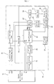
- FIG. 1 is a block diagram of an artificial intelligence robot toy according to the present invention
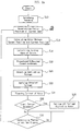
- FIGs. 2a and 2b are flowcharts illustrating operation flows of an artificial intelligence robot toy according to the present invention
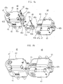
- FIGs. 3a and 3b are disassembled perspective views of a joint mechanism part in an artificial intelligence robot toy according to the present invention
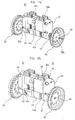
- FIGs. 4a and 4b to FIGs. 7A and 7B are perspective views of first to eleventh joint parts configured to couple the joint mechanism part;
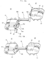
- FIGs. 8a to 18a are disassembled perspective views illustrating coupling states between the joint mechanism part and the first to eleventh joint parts
- FIGs. 8b to 18b are assembled perspective views illustrating coupling states between the joint mechanism part and the first to eleventh joint parts
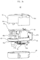
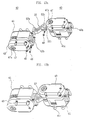
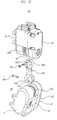
- FIG. 19 is a perspective view of a coupling state according to an embodiment of the present invention.
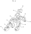
- FIG. 20 is a coupling state of a robot toy according to another embodiment of the present invention.
- FIG. 1 is a block diagram of an artificial intelligence robot toy according to the present invention
- FIGs. 3a and 3b are disassembled perspective views of a joint mechanism part in an artificial intelligence robot toy according to the present invention
- FIGs. 4a and 4b to FIGs. 7a and 7b are perspective views of first to eleventh joint parts configured to couple the joint mechanism part.
- an artificial intelligence robot toy includes: a plurality of joint mechanism parts 40 assemblable and disassemblable to form various shapes of robots; a master main-processor unit board 10 provided in any one of the plurality of joint mechanism parts 40, for outputting a robot control signal such that another joint mechanism part or other joint mechanism parts have a predetermined operation pattern; a plurality of joint control part 20 respectively provided in the remaining joint mechanism parts, for transmitting and receiving data to and from the master main-processor unit board 10 while operating the corresponding joint mechanism parts by using at least one pattern, based on the operation pattern of the master main-processor unit board 10; and first to eleventh joint parts 50 to 60 for coupling the plurality of joint mechanism parts 40 so as to form the various shapes of robots.
- the joint mechanism part 40 includes: a lower case 41 provided with a guide part 41a formed at one end thereof, an opening 41b formed at the other end thereof facing the guide part 41a, and two coupling holes 41c formed protruding outwardly from an outer wall thereof such that second to fifth joint parts 51 to 54 may be inserted; a housing 42 coupled to the lower case 41, the housing 42 being coupled with the master main-processor unit board 10 or the joint control part 20 at a side surface of the housing 42, coupled with the rotatable gear shaft 42a at one end thereof, the gear shaft 42a being protruding in a vertical direction and having a screw hole 42c such that the second to fifth joint parts 51 to 54 are coupled attachable or detachable, the housing 42 having a rectangular insertion part 42b of which one surface is opened and which the first to third joint parts 50 to 53, sixth, seventh and eleventh joint part 55, 56 and 60 are detachably inserted into and coupled to, and screw holes 45a and 46a
- the joint control part 20 includes: an inverse power preventing part 21 supplied with a non-driving voltage of the master main-processor unit board 10 to prevent an inverse voltage input to the master main-processor unit board 10; a constant voltage part 22 for converting and outputting the output non-driving voltage of the inverse power preventing part 21 to a constant level of digital voltage; a filter part 23 for filtering a noise including a ripple voltage from the supply voltage of the constant voltage part 22 and supplying a filtered voltage; a voltage detecting part 25 for detecting the level of the non-driving voltage inputted from the inverse power preventing part 21 and outputting a resultant voltage; a motor 30 coupled to a lower surface of the housing 42 of the joint mechanism part 40 by two screws and rotating clockwise or counterclockwise; a motor driving part 27 for controlling and driving the motor 30 in a pulse width modulation (PWM) way according to the voltages obtained by the constant voltage part 22 and the inverse power preventing part 21; a gear
- the gear part 31, as shown in FIGs. 3a and 3b, includes a first gear 31a coupled to the shaft of the motor 30 protruded through the upper surface of the housing 42 and rotated, a second gear 31b in mesh with the first gear 31a, and a third gear 31c formed in the gear shaft 42a of the joint mechanism part 40, and in mesh with the second gear 31b to decelerate the rotational ratio.
- the first joint part 50 is a cylindrical shaft having a predetermined length, the cylindrical shaft having a pentagonal insertion groove 50a formed at one end thereof and a rectangular insertion piece 50b formed at the other end thereof such that the joint part 50 is inserted onto the coupling shaft 47 through the slot or hole 43a of the joint mechanism part 40 and inserted into the insertion part 42b through the guide part 41a of another joint mechanism part.
- the first joint part 50 has a vertical penetration hole 50c penetrating from the pentagonal insertion groove 50a to the insertion piece 50b.
- each of the second and third joint parts 51 and 52 has a spanner type insertion hole 51b, 52b with an axial hole 51c, 52c formed at one end of a shaft thereof and a rectangular insertion piece 51a, 52a formed at the other end of the shaft so as to be inserted onto the gear shaft 42a and the insertion parts 42b of the other or another joint mechanism parts through the guide part 41a of the one joint mechanism part 40.
- the shaft of the second joint part 51 is a straight-line type that is short in length between the insertion hole 51b and the insertion piece 51a
- the shaft of the third joint part 52 is a curved type that is long in length between the insertion hole 52b and the insertion piece 52a.
- the fourth joint part 53 has spanner type insertion holes 53a and 53b formed at both ends of a shaft thereof so as to be inserted onto the gear shaft 42a of the one joint mechanism part 40 and the guide part 41a of other joint mechanism parts.
- the two insertion holes 53a and 53b of the fourth joint part 53 are arranged at an angle of 90 degrees with reference to the shaft.
- the fifth joint part 54 has a pentagonal insertion groove 54a formed at one end thereof and a spanner type insertion hole 54b formed at the other end thereof so as to be respectively inserted onto the coupling shaft 47 through the slot 43a of the one joint mechanism part and inserted onto the gear shaft 42a through the guide part 41a of the another joint mechanism parts. Also, the fifth joint part 54 has a vertical penetration hole penetrating from the pentagonal insertion groove 54a to the insertion hole 54b, and an axial hole 54c formed at the insertion hole 54b side to is perpendicular to the vertical penetration hole 54d.
- each of the sixth and seventh joint parts 55 and 56 has rectangular insertion pieces 55a, 55b, 56a, 56b formed at both ends of a shaft thereof such that when the one joint mechanism part 40 is coupled with another joint mechanism part 40, the rectangular insertion pieces 55a, 55b, 56a, 56b are inserted into the insertion part 42b of the joint mechanism part 40.
- the shaft of the sixth joint part 55 is short in length between both insertion pieces 55a and 55b, while the shaft of the seventh joint part 56 is long in length between both insertion pieces 56a and 56b.
- the eighth joint part 57 is an approximately triangular plate shape having a constant thickness, and has rectangular insertion holes 57a, 57b arranged at an angle of 90 degrees so as to connect one joint mechanism part 40 with other joint mechanism parts.
- the rectangular holes 57a and 57b is characterized in that each of which outer surface is opened.
- the ninth and tenth joint parts 58 and 59 are inserted onto the coupling shaft 47 of the joint mechanism parts 40 to function as a wheel or a wing, and each of them has a pentagonal insertion hole 58a, 59a formed protruding from a center portion thereof. Also, each of the ninth and tenth joint parts 58 has an axial hole 58b, 59b penetrating the pentagonal insertion groove 58a, 59a.
- the eleventh joint part 60 is inserted into the insertion part 42b of the joint mechanism parts 40 to serve as a foot of the robot toy, and has a rectangular insertion piece 60a at one end of a shaft thereof and a hemispherical rolling part 60b, which is wider in area than the insertion piece 60a.
- the housing 42 is received in the lower case 41 having the guide part 41a at one side thereof and the opening 41b at the other side thereof.
- the housing 42 houses the motor 30, the gear part 31, and the joint control part 20.
- the master main-processor unit board 10, etc. is coupled in the housing 42.
- the upper case 43 is covered on the lower case 41.
- the upper case 43, the lower case 41 and the housing 42 are stably fixed by screwing four screws, so that one joint mechanism part 40 is formed.
- the coupling shaft 47 coupled with the third gear 31c of the gear part 31, is positioned at the slot 43a of the upper case 43, and the gear shaft 42a and the insertion part 42b of the housing 42 are protruded respectively toward the guide part 41a of the lower case 41 and the opening part 41b of the lower case 41.
- the first joint part 50 shown in FIG. 4a has the pentagonal insertion groove 50a formed at one end of the shaft thereof and the rectangular insertion piece 50b formed at the other end of the shaft thereof, and is, as shown in FIGs. 10a and 10b, used to connect the coupling shaft 47 of one joint mechanism part 40 with the insertion part 42b of the other joint mechanism parts.
- the first joint part 50 is inserted onto the coupling shaft 47 of one joint mechanism part 40 through the insertion groove 50a thereof, and then a screw 48 is screwed with the screw hole 47a of the coupling shaft 47 through the insertion groove 50a of the first joint part 50, so that the first joint part 50 is coupled with the coupling shaft 47 of the joint mechanism part 40.
- the insertion piece 50b of the first joint part 50 is inserted into the insertion part 42b of another joint mechanism part, and then two screws 45 and 46 are inserted into the screw holes 45a and 46a formed in the insertion part 42b and are then screwed by nuts, so that two joint mechanism parts are assembled as shown in FIG. 10b.
- Each of the second and third joint parts 51 and 52 shown in FIGs. 4b and 4c has the spanner type insertion hole 51b, 52b formed at one end of the shaft thereof and the rectangular insertion piece 51a, 52a formed at the other end of the shaft, and is, as shown in FIGs. 8a, 8b, 13a and 13b, used to connect the gear shaft 42a of one joint mechanism part 40 with the insertion part 42b of other joint mechanism parts.
- FIGs. 8a, 8b, 13a and 13b used to connect the gear shaft 42a of one joint mechanism part 40 with the insertion part 42b of other joint mechanism parts.
- the second and third joint parts 51 and 52 are inserted onto the gear shaft 42a of one joint mechanism part 40 through the insertion holes 51b and 52b thereof, and then a screw 49 is inserted into the axial holes 51c and 52c of the insertion holes 51b and 52b, and the screw hole 42c of the gear shaft 42a corresponding to the axial holes 51c and 52c, and is screwed so that the second and third joint parts 51 and 52 are not released from the gear shaft 42a.
- the insertion pieces 51a and 52a of the second and third joint parts 51 and 52 are coupled in the same manner as that of the first joint part 50, so that an assembly is completed as shown in FIGs. 8b and 13b.
- the fourth joint part 53 shown in FIG. 5A has spanner type insertion holes 53a and 53b formed at both ends of the shaft thereof, and is, as shown in FIG. 17, used to connect the gear shaft 42a of one joint mechanism part 40 with the gear shaft 42a of other joint mechanism parts.
- the coupling method of both the insertion holes 53a and 53b is the same as that coupling the insertion holes 51b and 52b of the second and third joint parts 51 and 52 to the gear shaft 42a.
- the fifth joint part 54 shown in FIG. 5b has the pentagonal insertion groove 54a formed at one end of the shaft thereof and the spanner type insertion hole 54b formed at the other end of the shaft thereof, and as shown in FIGs. 9a and 9b, is inserted onto the coupling shaft 47 through the slot 43a of one joint mechanism part at the insertion groove 54a thereof, and the insertion hole 54b is inserted onto the gear shaft 42a through the guide part 41a of the other joint mechanism parts an coupled.
- the pentagonal insertion groove 54a is coupled in the same manner as the insertion groove 50a of the first joint part 50, and the spanner type insertion hole 54b is coupled in the same manner as the insertion hole 51b of the second joint part 51 is coupled with the gear shaft 42a.
- Each of the sixth and seventh joint parts 55 and 56 shown in FIGs. 6a and 6b has rectangular insertion pieces 55a, 55b, 56a, 56b formed at both ends of the shaft thereof, and are, as shown in FIGs. 11a, 11b, 15a and 15b, respectively, inserted into the insertion part 42b of one joint mechanism part and the insertion part of another joint mechanism part and coupled.
- the sixth joint part 55 has the short shaft between both insertion pieces 55a and 55b
- the seventh joint part 56 has the shaft longer than the sixth joint part 55.
- the coupling method of the sixth and seventh joint parts 55 and 56 are the same as the method coupling the insertion piece 51a of the second joint part 51 to the insertion part 42b.
- the eighth joint part 57 shown in FIG. 6c has the rectangular insertion holes 57a, 57b arranged at an angle of 90 degrees, and is, as shown in FIGs. 14a and 14b, used to rotatably connect the gear shaft 42a of one joint mechanism part 40 with the coupling shaft 47 of other joint mechanism parts.
- the insertion holes 57a and 57b of the eighth joint part 57 are forcibly inserted and coupled with the insertion pieces 50b and 51a of the first and second joint parts 50 and 51, so that the assembly is completed as shown in FIG. 14b.
- Each of the wheel type ninth joint part 58 and the wing type tenth joint part 59 shown in FIGs. 7a and 7b has the pentagonal insertion hole 58a, 59a formed protruding from a center portion thereof, and is, as shown in FIGs. 12a, 12b, 16a and 16b, inserted onto the coupling shaft 47 of the joint mechanism part 40 to serve as a wheel or a wing.
- the insertion grooves 58a, 59a of the ninth and tenth joint parts 58 and 59 are inserted onto the coupling shaft 47 of the two joint mechanism parts 40 and a screw is inserted into the axial holes 58b, 59b of the insertion grooves 58a, 59a and screwed so that the assembly is completed as shown in FIGs. 12b and 16b.
- the tenth joint part 59 is coupled with the joint mechanism 40 and is advantageous in climbing steps having a low height difference while rotating.
- the eleventh joint part 60 shown in FIG. 7c has the rectangular insertion piece 60a at one end of the shaft thereof and the hemispherical rolling part 60b at the other end of the shaft thereof, which is wider in area than the insertion piece 60a, and is, as shown in FIGs. 18a and 18b, used inserted into the insertion part 42b of the joint mechanism parts 40.
- the rolling part 60b serve as a foot of the robot toy during the movement of the robot toy, and the insertion piece 60a is coupled in the same manner as that of the aforementioned joint parts so that the assembly is completed as shown in FIG. 18b.
- the plurality of joint mechanism parts 40 are coupled in series or parallel through two power lines, a single transmission line and a reception line, and are connected to the master main-processor unit board 10.
- the first to eleventh joint parts 50 to 60 are selectively used according to the shapes of the robot toys desired for assembling, to couple the plurality of joint mechanism parts 40 sequentially.
- the master main-processor unit board 10 received in one joint mechanism part reads in a current position from the main-process unit 24 of the joint control part 20 received in the plurality of joint mechanism parts 40, i.e., reads in the angle of the joint through the reception port (Rx) of one line if the joint mechanism part 40 is a hand, reads in a moved distance through the reception port (Rx) of one line if the joint mechanism part 40 is a foot, and reads in a moved angle through the reception port (Rx) of one line if the joint mechanism part 40 is tail or head.
- the action mode (operation mode) of each of the joint mechanism parts 40 is set in a motor down mode. Thereafter, a command is transmitted to each of the joint mechanism parts 40 through the transmission port (Tx) of one line, and then current position and current are received through the reception port (Rx) of one line.
- the action mode (operation mode) of the plurality of joint mechanisms 40 is set in a position sense mode, and then a command is transmitted to the respective joint mechanism parts 40.
- the present position and the present current are received to ascertain whether or not there exists a variation between the previous position and the present position, and also to ascertain the state of the present current.
- a new action is planned using the ascertained position variation and the current state information. If the plan is completed, steps of computing next target position and velocity of each of the joint mechanism parts suitable for new actions, i.e., steps of computing the motion angle of the joints, are repeatedly performed.
- the main-processor unit 24 of the joint control part 20 received in each of the joint mechanism parts 40 initializes variables if an operation starts through a switch (S10).
- the main-processor unit 24 Ascertains a current output position of the gear part 31 through the third A/D converter 33 and the rotation sensing part 32 (S12), and calculates an error between the new target position provided by the master main-processor unit board 10 and the ascertained current position (S14). Then, variation rate in the calculated errors is computed (S16) and a proportional differential control arithmetic is performed (S18).
- a non-driving voltage provided from the master main-processor unit board 10 is detected through the inverse voltage preventing part 21, the voltage detecting part 25 and the first A/D converter 26 (S20), and a real voltage applied to the motor 30 is calculated from the proportional differential arithmetic value and the level of the detected non-driving voltage.
- the calculated voltage is modulated to a PWM signal, and the PWM signal is applied to the motor 30 through the motor driving part 27 together with the direction (DIR) signal to drive the motor 30 (S22).
- the joint mechanism part corresponds to a hand, the angle of the joint traces the target position. If the joint mechanism part corresponds to a foot, the moved distance traces the target position. If the joint mechanism part corresponds to tail or head, left and right motion angles trace the target position.
- the main-processor unit 24 detects the current of the motor 30 through the current detecting part 28 and the second A/D converter 29 (S24) and determines whether or not the detected current exceeds a set limitation current (S26). If it is determined that the detected current exceeds the set limitation current, the main-processor unit 24 cuts off the voltage applied to the motor 30 (S28). If it is determined that the detected current does not exceed the set limitation current, the main-processor unit 24 determines whether or not the limitation current exceeds 1ms, i.e., repetition routine time elapses (S30).
- the main-processor unit 24 If it is determined that the limitation time does not exceeds the repetition routine time, the main-processor unit 24 maintains the standby state, while if it is determined that the limitation time exceeds the repetition routine time, the main-processor unit 24 repeatedly performs the steps after the step S10.
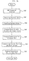
- the main-processor units 24 of the joint control parts 20 received in the respective joint mechanism parts 40 receive data through the reception port (Rx) (S42), and classify operation modes to be described later (S44).
- the main-processor units 24 change the operation mode variables and the target position (S46), and change the transmission port (Tx) thereof to an output port (S48).
- the main-processor unit 24 receives data from the master main-processor unit board 10 by using the transmission port (Tx) as an input port in a normal state, and if each operation thereof is ended, the main-processor unit 24 changes the transmission port (Tx) to the output port so as to transmit the result of the respective operations in the format of data.
- the main-processor unit 24 After changing the transmission port (Tx) to the output port, the main-processor unit 24 detects the current position of the motor 30, i.e., the current position of the corresponding joint mechanism part 40 and the current of the motor 30, and transmits the detected results to the master main-processor unit board 10 through the changed output port (S50). After transmitting the detected current position and current, the main-processor unit 24 changes the transmission port (Tx) to the input port (S52), and completes the interrupt operation.
- the aforementioned operation modes are classified into position send mode, motor down mode, power down mode and wheel act mode.
- the position send mode indicates an operation mode in which the motor 30 is operated for the position control, a position control range is 0 - 332.3°, and the present position and current thereof are transmitted after the position control command is received.
- the motor down mode indicates a mode in which the motor power is changed to zero, a user can arbitrarily change the motor position by his (or her) power, and the present position and current return to after a command is received.
- the motor down mode operates as a sensor used for changing the position by an external force.
- the power down mode is used for minimizing the operation power consumption of the motor system and the system power.
- the power down mode returns the IDs and positions of the corresponding joint mechanism parts 40 after receiving a command, and is used to want to know the motor IDs of the corresponding joint mechanism parts 40.
- the wheel act mode operates the motor to drive the wheel, makes it possible to rotate the wheel clockwise or counterclockwise by an angle of 360° and control the velocity of the wheel.
- rotation amount and present position are transmitted after a command is received.
- the aforementioned operation modes receive commands from the master main-processor unit board 10.
- robot toys according to the present invention provide users with love and interest. Also, it is possible to address all functions of such robot toys to a maximum degree at a low manufacturing cost and to assemble and control the robot toys requesting motions in various shapes with ease by using one kind of joint mechanism part. Further, the inventive robot toys provide users with easy disorder coping and expandable assembling capability.
Abstract
Description
- The present invention relates to an artificial intelligence robot toy, and more specifically, to an artificial intelligence robot toy that can be easily assembled and controlled in various shapes by using one kind of joint motor. In particular, the present invention is directed toward an artificial intelligence robot toy and control method thereof in which additional extension of the joint is compatible with the easiness in the modification design and coping design.
- In general, toys, particularly robot toys needing motions, are classified into a highgrade type in which a motor is driven by electric power, and a simple type using a mainspring or the like. The highgrade type robot toys are controlled by a wireless remote controller or a wiring remote controller, and are moved by controlling a motor operation inside the body to move joints.
- In the controls of the robot toys using such remote controllers, whoever is skilled to the handling of the remote controller can control the robot toys, but users who are not accustomed to the handling of the remote controller do not feel interest and love in the robot toys. In particular, after operating all the functions of such robot toys that request a motion as above several times, a user is easily fed up and carefree with the robot toys, so that there exists a drawback in that the real use lifecycle of these robot toys is short.
- Also, since the robot toys moved using joints are marketable in the form of a single product, it is impossible that a user extends an assembly structure of one set robot toy to various shapes, for instance, puppy robot, dinosaur robot, or android. In particular, for mechanical assembling electronic circuits and control circuits used for controlling joints, particular apparatuses and high costs are required, which is burdensome to general users. In addition, when a motor or control circuit is disordered or a robot mechanism is fractured, the repair of the disorder may be impossible or problematic.
- Accordingly, it is desirable to provide a robot toy that can solve the above problems, is low under the aspect of costs, is variously expandable and contractible in shape in aspect of reliability, and can be assembled with ease.
- An object of the present invention is to provide an artificial intelligence robot toy and control method thereof in which various shapes of robot toys requesting motions using one kind of joint motor are easily assemblable, changeable in shape, and controllable.
- Another object of the present invention is to provide an artificial intelligence robot toy and control method thereof in which the respective parts including legs are assemblable in an independent unit, and the assembling time and the number of parts are reduced substantially.
- A further object of the present invention is to provide an artificial intelligence robot toy in which an additional extension of joint, a modification of the design of the robot toy and disorder coping are easy.
- A still further object of the present invention is to provide an artificial intelligence robot toy in which proper motion and response are performed according to various shapes of robot mechanisms, and price competitiveness and motion reliability are secured.
- Additional advantages, objects, and features of the invention will be set forth in part in the description which follows and in part will become apparent to those having ordinary skill in the art upon examination of the following or may be learned from practice of the invention. The objectives and other advantages of the invention may be realized and attained by the structure particularly pointed out in the written description and claims hereof as well as the appended drawings.
- The above underlying problems are solved according to the independent claims. The dependent claims relate to preferred embodiments of the concept of the present invention. To achieve these objects and other advantages and in accordance with the purpose of the invention, as embodied and broadly described herein, there is provided an artificial intelligence or computer-controlled robot toy comprising: a plurality of joint mechanism parts assemblable and disassemblable to form various shapes of robots; a master main-processor unit board provided in one of the plurality of joint mechanism parts, for outputting a robot control signal such that another joint mechanism parts have a predetermined operation pattern; a plurality of joint control means respectively provided in the remaining joint mechanism parts other than the selected joint mechanism part, for transmitting and receiving data to and from the master main-processor unit board while operating the corresponding joint mechanism parts by using at least one pattern, based on the operation pattern of the master main-processor unit board; and a joint means for coupling the plurality of joint mechanism parts so as to form the various shapes of robots.
- Alternatively, the joint mechanism part comprises: a lower case provided with a guide part formed at one end thereof, an opening formed at the other end thereof, and a coupling hole formed at an outer wall thereof such that the joint means is inserted; a housing coupled in the lower case, for stably supporting the master main-processor unit board or the joint control means, the housing having a gear shaft coupled with the joint means at one end of the housing and protruded in a vertical direction to be rotatable, and an insertion part onto which the joint means is inserted; an upper case coupled with the lower case and having an slot formed at a side sealingly closing the housing; and a coupling shaft extending from an end of the gear shaft and protruded through the slot of the upper case, the coupling shaft being coupled with the joint means.
- Alternatively, the joint control means comprises: an inverse power preventing part supplied with a non-driving voltage to prevent an inverse voltage; a constant voltage part for converting and outputting the output non-driving voltage of the inverse power preventing part to a constant level of digital voltage; a filter part for filtering a noise including a ripple voltage from the supply voltage of the constant voltage part and supplying a filtered voltage; a voltage detecting part for detecting level of the non-driving voltage obtained from the inverse power preventing part; a motor coupled to the housing of the joint mechanism part and rotating clockwise or counterclockwise; a motor driving part for controlling and driving the motor in a pulse width modulation (PWM) way according to the voltage obtained by the constant voltage part and the inverse power preventing part; a gear part coupled to a shaft of the motor, for decelerating a rotational ratio of the motor, transferring the decelerated rotational ratio to the gear shaft, and controlling the operation pattern of the joint mechanism part; a rotation sensing part driven by the supply voltage of the filter part, for sensing the rotation of the gear part; a current detecting part for detecting a load current of the motor through the motor driving part; first to third A/D converters for converting and outputting the output signals of the voltage detecting part, the current detecting part and the rotation sensing part to digital signals respectively; and a main-processor unit for outputting a PWM signal and a direction signal depending on operation modes provided from the master main-processor unit board to drive the motor and respectively computing the voltage level, the current level and the rotational ratio obtained by the first to third A/D converters and transmitting the computed voltage level, the current level and the rotational ratio to the master main-processor unit board.
- In an aspect of the present invention, there is provided a method for controlling an artificial intelligence robot toy, the method comprising the steps of: (a) determining a current position of joints from a rotation sensing part informing a current position of joint mechanism parts; (b) obtaining an error from the determined current position and a target position provided by a master main-processor unit board; (c) computing a variation rate of the obtained error and then performing a proportional differential control arithmetic of the computed variation rate; (d) calculating an application voltage of motors provided from the master main-processor unit board and detecting a current of the motors while supplying the calculated voltage; and (e) determining whether or not the detected current exceeds a limit current, when it is determined that the detected current exceeds the limit current, cutting off the voltage applied to the motors, and when it is determined that the detected current does not exceed the limit current, repeating the steps after the step (a).
- According to the present invention, various shapes of robot toys requesting motions are easily assemblable using one kind of joint motor.
- As a result, it is possible to issue all the functions of the robot toy at low manufacturing cost. Also, various shapes of robot mechanisms are more easily expandable, assemblable and controllable. Further, disorder coping is easy.
- It is to be understood that both the foregoing general description and the following detailed description of the present invention are exemplary and explanatory and are intended to provide further explanation of the invention as claimed.
- The accompanying drawings, which are included to provide a further understanding of the invention and are incorporated in and constitute a part of this application, illustrate embodiment(s) of the invention and together with the description serve to explain the principle of the invention. In the drawings:
- FIG. 1 is a block diagram of an artificial intelligence robot toy according to the present invention;
- FIGs. 2a and 2b are flowcharts illustrating operation flows of an artificial intelligence robot toy according to the present invention;
- FIGs. 3a and 3b are disassembled perspective views of a joint mechanism part in an artificial intelligence robot toy according to the present invention;
- FIGs. 4a and 4b to FIGs. 7A and 7B are perspective views of first to eleventh joint parts configured to couple the joint mechanism part;
- FIGs. 8a to 18a are disassembled perspective views illustrating coupling states between the joint mechanism part and the first to eleventh joint parts;
- FIGs. 8b to 18b are assembled perspective views illustrating coupling states between the joint mechanism part and the first to eleventh joint parts;
- FIG. 19 is a perspective view of a coupling state according to an embodiment of the present invention; and
- FIG. 20 is a coupling state of a robot toy according to another embodiment of the present invention.
- Reference will now be made in detail to the preferred embodiments of the present invention, examples of which are illustrated in the accompanying drawings. Wherever possible, the same reference numbers will be used throughout the drawings to refer to the same or like parts.
- FIG. 1 is a block diagram of an artificial intelligence robot toy according to the present invention, FIGs. 3a and 3b are disassembled perspective views of a joint mechanism part in an artificial intelligence robot toy according to the present invention, and FIGs. 4a and 4b to FIGs. 7a and 7b are perspective views of first to eleventh joint parts configured to couple the joint mechanism part.
- In an embodiment of the present invention, as shown in FIGs. 1 and 3, an artificial intelligence robot toy includes: a plurality of
joint mechanism parts 40 assemblable and disassemblable to form various shapes of robots; a master main-processor unit board 10 provided in any one of the plurality ofjoint mechanism parts 40, for outputting a robot control signal such that another joint mechanism part or other joint mechanism parts have a predetermined operation pattern; a plurality ofjoint control part 20 respectively provided in the remaining joint mechanism parts, for transmitting and receiving data to and from the master main-processor unit board 10 while operating the corresponding joint mechanism parts by using at least one pattern, based on the operation pattern of the master main-processor unit board 10; and first to eleventhjoint parts 50 to 60 for coupling the plurality ofjoint mechanism parts 40 so as to form the various shapes of robots. - As shown in FIGs. 3a and 3b, the
joint mechanism part 40 includes: alower case 41 provided with aguide part 41a formed at one end thereof, an opening 41b formed at the other end thereof facing theguide part 41a, and twocoupling holes 41c formed protruding outwardly from an outer wall thereof such that second to fifthjoint parts 51 to 54 may be inserted; ahousing 42 coupled to thelower case 41, thehousing 42 being coupled with the master main-processor unit board 10 or thejoint control part 20 at a side surface of thehousing 42, coupled with therotatable gear shaft 42a at one end thereof, thegear shaft 42a being protruding in a vertical direction and having ascrew hole 42c such that the second to fifthjoint parts 51 to 54 are coupled attachable or detachable, thehousing 42 having arectangular insertion part 42b of which one surface is opened and which the first to thirdjoint parts 50 to 53, sixth, seventh and eleventhjoint part screw holes insertion part 42b in a vertical direction and coupled by twoscrews upper case 43 coupled with thelower case 41 by four screws and having a slot orhole 43a formed at one end configured to sealingly close thehousing 42; and apentagonal coupling shaft 47 formed extending from an end of thegear shaft 42a and protruded through the slot orhole 43a of theupper case 43, the coupling shaft having ascrew hole 47a at an upper center thereof where the first, fifth, ninth and tenthjoint parts - Referring to again FIG. 1, the
joint control part 20 includes: an inversepower preventing part 21 supplied with a non-driving voltage of the master main-processor unit board 10 to prevent an inverse voltage input to the master main-processor unit board 10; aconstant voltage part 22 for converting and outputting the output non-driving voltage of the inversepower preventing part 21 to a constant level of digital voltage; afilter part 23 for filtering a noise including a ripple voltage from the supply voltage of theconstant voltage part 22 and supplying a filtered voltage; avoltage detecting part 25 for detecting the level of the non-driving voltage inputted from the inversepower preventing part 21 and outputting a resultant voltage; amotor 30 coupled to a lower surface of thehousing 42 of thejoint mechanism part 40 by two screws and rotating clockwise or counterclockwise; amotor driving part 27 for controlling and driving themotor 30 in a pulse width modulation (PWM) way according to the voltages obtained by theconstant voltage part 22 and the inversepower preventing part 21; agear part 31 coupled to a shaft of themotor 30 penetrating an upper surface of thehousing 42, for decelerating a rotational ratio of themotor 30, transferring the decelerated rotational ratio to thegear shaft 42a, and controlling the operation pattern of thejoint mechanism part 40; arotation sensing part 32 driven by the supply voltage of thefilter part 23, for sensing the rotation of thegear part 31; a current detectingpart 28 for detecting a load current of themotor 30 through themotor driving part 27; first to third A/D converters voltage detecting part 25, the current detectingpart 28 and therotation sensing part 32 to digital signals respectively; and a main-processor unit 24 for outputting a pulse width modulation (PWM) signal and a direction (DIR) signal depending on operation modes provided from the master main-processor unit board 10 to control the operation of themotor 30 through themotor driving part 27 and respectively computing the voltage level, the current level and the rotational ratio or rotational speed obtained by the first to third A/D converters - The
gear part 31, as shown in FIGs. 3a and 3b, includes afirst gear 31a coupled to the shaft of themotor 30 protruded through the upper surface of thehousing 42 and rotated, asecond gear 31b in mesh with thefirst gear 31a, and athird gear 31c formed in thegear shaft 42a of thejoint mechanism part 40, and in mesh with thesecond gear 31b to decelerate the rotational ratio. - As shown in FIG. 4a, the first
joint part 50 is a cylindrical shaft having a predetermined length, the cylindrical shaft having apentagonal insertion groove 50a formed at one end thereof and arectangular insertion piece 50b formed at the other end thereof such that thejoint part 50 is inserted onto thecoupling shaft 47 through the slot orhole 43a of thejoint mechanism part 40 and inserted into theinsertion part 42b through theguide part 41a of another joint mechanism part. Also, the firstjoint part 50 has avertical penetration hole 50c penetrating from thepentagonal insertion groove 50a to theinsertion piece 50b. - As shown in FIGs. 4b and 4c, each of the second and third
joint parts type insertion hole axial hole rectangular insertion piece gear shaft 42a and theinsertion parts 42b of the other or another joint mechanism parts through theguide part 41a of the onejoint mechanism part 40. Herein, the shaft of the secondjoint part 51 is a straight-line type that is short in length between theinsertion hole 51b and theinsertion piece 51a, while the shaft of the thirdjoint part 52 is a curved type that is long in length between theinsertion hole 52b and theinsertion piece 52a. - As shown in FIG. 5a, the fourth
joint part 53 has spannertype insertion holes gear shaft 42a of the onejoint mechanism part 40 and theguide part 41a of other joint mechanism parts. The twoinsertion holes joint part 53 are arranged at an angle of 90 degrees with reference to the shaft. - As shown in FIG. 5b, the fifth
joint part 54 has apentagonal insertion groove 54a formed at one end thereof and a spannertype insertion hole 54b formed at the other end thereof so as to be respectively inserted onto thecoupling shaft 47 through theslot 43a of the one joint mechanism part and inserted onto thegear shaft 42a through theguide part 41a of the another joint mechanism parts. Also, the fifthjoint part 54 has a vertical penetration hole penetrating from thepentagonal insertion groove 54a to theinsertion hole 54b, and anaxial hole 54c formed at theinsertion hole 54b side to is perpendicular to thevertical penetration hole 54d. - As shown in FIGs. 6a and 6b, each of the sixth and seventh
joint parts rectangular insertion pieces joint mechanism part 40 is coupled with anotherjoint mechanism part 40, therectangular insertion pieces insertion part 42b of thejoint mechanism part 40. Herein, the shaft of the sixthjoint part 55 is short in length between bothinsertion pieces joint part 56 is long in length between bothinsertion pieces - As shown in FIG. 6c, the eighth
joint part 57 is an approximately triangular plate shape having a constant thickness, and hasrectangular insertion holes joint mechanism part 40 with other joint mechanism parts. Therectangular holes - Also, as shown in FIGs. 7a and 7b, the ninth and tenth
joint parts coupling shaft 47 of thejoint mechanism parts 40 to function as a wheel or a wing, and each of them has apentagonal insertion hole joint parts 58 has anaxial hole pentagonal insertion groove - Lastly, the eleventh
joint part 60, as shown in FIG. 7c, is inserted into theinsertion part 42b of thejoint mechanism parts 40 to serve as a foot of the robot toy, and has arectangular insertion piece 60a at one end of a shaft thereof and ahemispherical rolling part 60b, which is wider in area than theinsertion piece 60a. - Hereinafter, preferred embodiments having the above construction according to the present invention will be described in detail with reference to FIGs. 1 to 20.
- To assemble various shapes of robots needing a motion using one kind of joint mechanism part, as shown in FIGs. 3a and 3b, the
housing 42 is received in thelower case 41 having theguide part 41a at one side thereof and theopening 41b at the other side thereof. At this time, thehousing 42 houses themotor 30, thegear part 31, and thejoint control part 20. Alternatively, the master main-processor unit board 10, etc., is coupled in thehousing 42. After that, theupper case 43 is covered on thelower case 41. Theupper case 43, thelower case 41 and thehousing 42 are stably fixed by screwing four screws, so that onejoint mechanism part 40 is formed. At this time, thecoupling shaft 47 coupled with thethird gear 31c of thegear part 31, is positioned at theslot 43a of theupper case 43, and thegear shaft 42a and theinsertion part 42b of thehousing 42 are protruded respectively toward theguide part 41a of thelower case 41 and theopening part 41b of thelower case 41. - To assembly a desired shape of robot toy using a plurality of joint mechanism parts each having the above construction, there are needed the first to eleventh
joint parts 50 to 60 as shown in FIGs. 4 to 7. - The first
joint part 50 shown in FIG. 4a has thepentagonal insertion groove 50a formed at one end of the shaft thereof and therectangular insertion piece 50b formed at the other end of the shaft thereof, and is, as shown in FIGs. 10a and 10b, used to connect thecoupling shaft 47 of onejoint mechanism part 40 with theinsertion part 42b of the other joint mechanism parts. In other words, as shown in FIG. 10a, the firstjoint part 50 is inserted onto thecoupling shaft 47 of onejoint mechanism part 40 through theinsertion groove 50a thereof, and then ascrew 48 is screwed with thescrew hole 47a of thecoupling shaft 47 through theinsertion groove 50a of the firstjoint part 50, so that the firstjoint part 50 is coupled with thecoupling shaft 47 of thejoint mechanism part 40. Thereafter, theinsertion piece 50b of the firstjoint part 50 is inserted into theinsertion part 42b of another joint mechanism part, and then twoscrews insertion part 42b and are then screwed by nuts, so that two joint mechanism parts are assembled as shown in FIG. 10b. - Each of the second and third
joint parts type insertion hole rectangular insertion piece gear shaft 42a of onejoint mechanism part 40 with theinsertion part 42b of other joint mechanism parts. In other words, as shown in FIGs. 8a and 13a, the second and thirdjoint parts gear shaft 42a of onejoint mechanism part 40 through the insertion holes 51b and 52b thereof, and then ascrew 49 is inserted into theaxial holes screw hole 42c of thegear shaft 42a corresponding to theaxial holes joint parts gear shaft 42a. After that, theinsertion pieces joint parts joint part 50, so that an assembly is completed as shown in FIGs. 8b and 13b. - The fourth
joint part 53 shown in FIG. 5A has spannertype insertion holes gear shaft 42a of onejoint mechanism part 40 with thegear shaft 42a of other joint mechanism parts. Here, the coupling method of both theinsertion holes joint parts gear shaft 42a. - Like the fourth
joint part 53, the fifthjoint part 54 shown in FIG. 5b has thepentagonal insertion groove 54a formed at one end of the shaft thereof and the spannertype insertion hole 54b formed at the other end of the shaft thereof, and as shown in FIGs. 9a and 9b, is inserted onto thecoupling shaft 47 through theslot 43a of one joint mechanism part at theinsertion groove 54a thereof, and theinsertion hole 54b is inserted onto thegear shaft 42a through theguide part 41a of the other joint mechanism parts an coupled. At this time, thepentagonal insertion groove 54a is coupled in the same manner as theinsertion groove 50a of the firstjoint part 50, and the spannertype insertion hole 54b is coupled in the same manner as theinsertion hole 51b of the secondjoint part 51 is coupled with thegear shaft 42a. - Each of the sixth and seventh
joint parts rectangular insertion pieces insertion part 42b of one joint mechanism part and the insertion part of another joint mechanism part and coupled. Here, the sixthjoint part 55 has the short shaft between bothinsertion pieces joint part 56 has the shaft longer than the sixthjoint part 55. The coupling method of the sixth and seventhjoint parts insertion piece 51a of the secondjoint part 51 to theinsertion part 42b. - The eighth
joint part 57 shown in FIG. 6c has therectangular insertion holes gear shaft 42a of onejoint mechanism part 40 with thecoupling shaft 47 of other joint mechanism parts. In other words, in a state that theinsertion groove 50a of the firstjoint part 50 and theinsertion hole 51b of the secondjoint part 51 are coupled in the aforementioned manner, theinsertion holes joint part 57 are forcibly inserted and coupled with theinsertion pieces joint parts - Each of the wheel type ninth
joint part 58 and the wing type tenthjoint part 59 shown in FIGs. 7a and 7b has thepentagonal insertion hole coupling shaft 47 of thejoint mechanism part 40 to serve as a wheel or a wing. First, two joint mechanism parts are contacted with each other, and a screw is inserted into thecoupling hole 41c and screwed so that the two joint mechanism parts are stably coupled. After that, theinsertion grooves joint parts coupling shaft 47 of the twojoint mechanism parts 40 and a screw is inserted into theaxial holes insertion grooves joint part 59 is coupled with thejoint mechanism 40 and is advantageous in climbing steps having a low height difference while rotating. - The eleventh
joint part 60 shown in FIG. 7c has therectangular insertion piece 60a at one end of the shaft thereof and the hemispherical rollingpart 60b at the other end of the shaft thereof, which is wider in area than theinsertion piece 60a, and is, as shown in FIGs. 18a and 18b, used inserted into theinsertion part 42b of thejoint mechanism parts 40. In particular, the rollingpart 60b serve as a foot of the robot toy during the movement of the robot toy, and theinsertion piece 60a is coupled in the same manner as that of the aforementioned joint parts so that the assembly is completed as shown in FIG. 18b. - Also, the plurality of
joint mechanism parts 40 are coupled in series or parallel through two power lines, a single transmission line and a reception line, and are connected to the master main-processor unit board 10. - Thus, the first to eleventh
joint parts 50 to 60 are selectively used according to the shapes of the robot toys desired for assembling, to couple the plurality ofjoint mechanism parts 40 sequentially. After a desired robot toy needing a motion as shown in FIG. 19 or FIG. 20 is assembled, if an operation starts through a switch (not shown in the drawings), the master main-processor unit board 10 received in one joint mechanism part reads in a current position from the main-process unit 24 of thejoint control part 20 received in the plurality ofjoint mechanism parts 40, i.e., reads in the angle of the joint through the reception port (Rx) of one line if thejoint mechanism part 40 is a hand, reads in a moved distance through the reception port (Rx) of one line if thejoint mechanism part 40 is a foot, and reads in a moved angle through the reception port (Rx) of one line if thejoint mechanism part 40 is tail or head. - Then, the action mode (operation mode) of each of the
joint mechanism parts 40 is set in a motor down mode. Thereafter, a command is transmitted to each of thejoint mechanism parts 40 through the transmission port (Tx) of one line, and then current position and current are received through the reception port (Rx) of one line. - After the current position of each of the
joint mechanism parts 40 is ascertained, preset target position and velocity are computed on the basis of the received current position and then the computed new target position and sampling time (velocity value, i.e., motion angle of joint) are transmitted through the transmission port (Tx) in accordance with communication protocol. After that, the action mode (operation mode) of the plurality ofjoint mechanisms 40 is set in a position sense mode, and then a command is transmitted to the respectivejoint mechanism parts 40. In other words, directly after the target position and velocity value are transmitted, the present position and the present current are received to ascertain whether or not there exists a variation between the previous position and the present position, and also to ascertain the state of the present current. Afterwards, a new action is planned using the ascertained position variation and the current state information. If the plan is completed, steps of computing next target position and velocity of each of the joint mechanism parts suitable for new actions, i.e., steps of computing the motion angle of the joints, are repeatedly performed. - In the meanwhile, the main-
processor unit 24 of thejoint control part 20 received in each of thejoint mechanism parts 40 initializes variables if an operation starts through a switch (S10). - After the initialization is released, the main-
processor unit 24 ascertains a current output position of thegear part 31 through the third A/D converter 33 and the rotation sensing part 32 (S12), and calculates an error between the new target position provided by the master main-processor unit board 10 and the ascertained current position (S14). Then, variation rate in the calculated errors is computed (S16) and a proportional differential control arithmetic is performed (S18). - After that, a non-driving voltage provided from the master main-
processor unit board 10 is detected through the inversevoltage preventing part 21, thevoltage detecting part 25 and the first A/D converter 26 (S20), and a real voltage applied to themotor 30 is calculated from the proportional differential arithmetic value and the level of the detected non-driving voltage. The calculated voltage is modulated to a PWM signal, and the PWM signal is applied to themotor 30 through themotor driving part 27 together with the direction (DIR) signal to drive the motor 30 (S22). - When the
motor 30 is driven, the first tothird gears gear part 31 of the correspondingjoint mechanism part 40 rotate, the corresponding joint mechanism part coupled to thegear shaft 42a and thecoupling shaft 47 through the first to eleventhjoint parts 50 to 60 traces the target position provided from the master main-processor unit board 10. - In the above, if the joint mechanism part corresponds to a hand, the angle of the joint traces the target position. If the joint mechanism part corresponds to a foot, the moved distance traces the target position. If the joint mechanism part corresponds to tail or head, left and right motion angles trace the target position.
- Thus, in a state that the respective
joint mechanism parts 40 are moved by themotor 30 and thegear part 31, the main-processor unit 24 detects the current of themotor 30 through the current detectingpart 28 and the second A/D converter 29 (S24) and determines whether or not the detected current exceeds a set limitation current (S26). If it is determined that the detected current exceeds the set limitation current, the main-processor unit 24 cuts off the voltage applied to the motor 30 (S28). If it is determined that the detected current does not exceed the set limitation current, the main-processor unit 24 determines whether or not the limitation current exceeds 1ms, i.e., repetition routine time elapses (S30). If it is determined that the limitation time does not exceeds the repetition routine time, the main-processor unit 24 maintains the standby state, while if it is determined that the limitation time exceeds the repetition routine time, the main-processor unit 24 repeatedly performs the steps after the step S10. - Thus, while performing motions with tracing the target position provided from the master main-
processor unit board 10, if interrupt is generated (S40), the main-processor units 24 of thejoint control parts 20 received in the respectivejoint mechanism parts 40 receive data through the reception port (Rx) (S42), and classify operation modes to be described later (S44). - Also, the main-
processor units 24 change the operation mode variables and the target position (S46), and change the transmission port (Tx) thereof to an output port (S48). Herein, the main-processor unit 24 receives data from the master main-processor unit board 10 by using the transmission port (Tx) as an input port in a normal state, and if each operation thereof is ended, the main-processor unit 24 changes the transmission port (Tx) to the output port so as to transmit the result of the respective operations in the format of data. - Next, after changing the transmission port (Tx) to the output port, the main-
processor unit 24 detects the current position of themotor 30, i.e., the current position of the correspondingjoint mechanism part 40 and the current of themotor 30, and transmits the detected results to the master main-processor unit board 10 through the changed output port (S50). After transmitting the detected current position and current, the main-processor unit 24 changes the transmission port (Tx) to the input port (S52), and completes the interrupt operation. - The aforementioned operation modes are classified into position send mode, motor down mode, power down mode and wheel act mode.
- The position send mode indicates an operation mode in which the
motor 30 is operated for the position control, a position control range is 0 - 332.3°, and the present position and current thereof are transmitted after the position control command is received. - The motor down mode indicates a mode in which the motor power is changed to zero, a user can arbitrarily change the motor position by his (or her) power, and the present position and current return to after a command is received. The motor down mode operates as a sensor used for changing the position by an external force.
- The power down mode is used for minimizing the operation power consumption of the motor system and the system power. The power down mode returns the IDs and positions of the corresponding
joint mechanism parts 40 after receiving a command, and is used to want to know the motor IDs of the correspondingjoint mechanism parts 40. - Lastly, the wheel act mode operates the motor to drive the wheel, makes it possible to rotate the wheel clockwise or counterclockwise by an angle of 360° and control the velocity of the wheel. In the wheel act mode, rotation amount and present position are transmitted after a command is received.
- The aforementioned operation modes receive commands from the master main-
processor unit board 10. - From the above descriptions, unlike the conventional art, which does not allow a user to expandably assemble one set of robot toy as various shapes of robot toys, for instance, puppy robot, dinosaur robot, or android, it can be well known that it is possible to expandably assemble various shapes of robot toys needing motions by using a plurality of joint mechanism parts corresponding to one kind.
- As described above, robot toys according to the present invention provide users with love and interest. Also, it is possible to address all functions of such robot toys to a maximum degree at a low manufacturing cost and to assemble and control the robot toys requesting motions in various shapes with ease by using one kind of joint mechanism part. Further, the inventive robot toys provide users with easy disorder coping and expandable assembling capability.
- It will be apparent to those skilled in the art that various modifications and variations can be made in the present invention. Thus, it is intended that the present invention covers the modifications and variations of this invention provided they come within the scope of the appended claims and their equivalents.
Claims (19)
- Artificial intelligence or computer-controlled robot toy, comprising:a plurality of joint mechanism parts (40) assemblable and disassemblable to form various shapes of robots;a master main-processor unit board (10) provided in one of the plurality of joint mechanism parts (40) and outputting a robot control signal such that another joint mechanism part or other joint mechanism parts (40) have a predetermined operation pattern;a plurality of joint control means (20) respectively provided in the remaining joint mechanism parts (40) other than the selected joint mechanism part (40), for transmitting and receiving data to and from the master main-processor unit board (10) while operating the corresponding joint mechanism parts (40) by using at least one pattern, based on the operation pattern of the master main-processor unit board (10) andjoint means (50 to 60) for coupling the plurality of joint mechanism parts (40) so as to form the various shapes of robots.
- Robot toy according to claim 1, wherein the joint mechanism part (40) comprises:a lower case (41) provided with a guide part (41a) formed at one end thereof, an opening (41b) formed at the other end thereof, and a coupling hole (41c) formed at an outer wall thereof such that joint means (51 to 54) may be inserted;a housing (42) coupled to the lower case (41) for stably supporting the master main-processor unit board (10) or the joint control means (20), the housing (42) having a rotatable gear shaft (42a) detachably coupled with the joint means (51 to 54) at one end of the housing (42) and protruding in a vertical direction, and an insertion part (42b) onto which the joint means (51 to 54) are inserted;an upper case (43) coupled with the lower case (41) and having a slot or hole (43a) formed at a side sealingly closing the housing (42) anda coupling shaft (47) extending from an end of the gear shaft (42a) and protruding through the slot (43a) of the upper case (43), the coupling shaft (47) being detachably coupled with the joint means (50, 54, 59).
- Robot toy according to claim 1 or 2, wherein the joint control means (20) comprise:an inverse power preventing part (21) supplied with a non-driving voltage to prevent an inverse voltage;a constant voltage part (22) for converting and outputting the output non-driving voltage of the inverse power preventing part (21) to a constant level of digital voltage;a filter part (23) for filtering a noise including a ripple voltage from the supply voltage of the constant voltage part (22) and supplying a filtered voltage;a voltage detecting part (25) for detecting the level of the non-driving voltage obtained from the inverse power preventing part (21) and outputting a resultant voltage;a motor (30) coupled to the housing (42) of the joint mechanism part (40) and rotating clockwise or counterclockwise;a motor driving part (27) for controlling and driving the motor (30) in a pulse width modulation (PWM) way according to the voltage obtained by the constant voltage part (22) and the inverse power preventing part (21);a gear part (31) coupled to a shaft of the motor (30) for decelerating the rotational speed of the motor (30), transferring the decelerated rotational speed to the gear shaft (42a), and controlling the operation pattern of the joint mechanism part (40);a rotation sensing part (32) driven by the supply voltage of the filter part (23), for sensing the rotation of the gear part (31);a current detecting part (28) for detecting a load current of the motor (30) through the motor driving part (27);first to third A/D converters (26, 29, 33) for converting into digital signals and outputting the output signals of the voltage detecting part (25), the current detecting part (28) and the rotation sensing part (32), respectively anda main-processor unit (24) for outputting a PWM signal and a direction signal (DIR) depending on operation modes provided from the master main-processor unit board (10) to drive the motor (30) and respectively computing the voltage level, the current level and the rotational ratio or speed obtained by the first to third A/D converters (26, 29, 33) and transmitting the computed voltage level, the current level and the rotational ratio to the master main-processor unit board (10).
- Robot toy according to any of claims 1 to 3, wherein the one master main-processor unit board (10) and a plurality of main-processor units (24) are connected in series through a single transmission port and a single reception port to transmit and receive data.
- Robot toy according to any of claims 1 to 4, wherein the joint means (51, 52) have a spanner type insertion hole (51b, 52b) formed at one end of a shaft and a rectangular insertion piece (51a, 52a) formed at the other end of the shaft so as to be detachably inserted onto the gear shaft (42a) and the insertion parts (42b) of the other or another joint mechanism parts (40) through the guide part (41a) of the one joint mechanism part (40).
- Robot toy according to claim 5, wherein the spanner type insertion hole (52b) of the joint means (52) is inclined at a predetermined angle by the shaft with respect to the rectangular insertion piece (52a).
- Robot toy according to claim 5, wherein the shaft between the spanner type insertion hole (51b) of the joint means (51) and the rectangular insertion piece (51a) is of straight-line type.
- Robot toy according to any of claims 1 to 7, wherein the joint means (50) are a cylindrical shaft having a predetermined length, the cylindrical shaft having a pentagonal insertion groove (50a) formed at one end thereof and a rectangular insertion piece (50b) formed at the other end thereof such that the joint means (50) may be inserted onto the coupling shaft (47) through the slot or hole (43a) of one of the joint mechanism parts (40) and inserted into the insertion parts (42b) of another joint mechanism part (40).
- Robot toy according to any of claims 1 to 8, wherein the joint means (53) have a spanner type insertion hole (53a, 53b) formed at both ends of a shaft of the joint means (53) such that the joint means may be inserted onto the gear shaft (42a) of the one joint mechanism part (40) and the guide part (41a) of another joint mechanism part (40).
- Robot toy according to claim 9, wherein the two insertion holes (53a, 53b) of the joint means (53) are arranged at an angle of 90 degrees to each other.
- Robot toy according to any of claims 1 to 10, wherein the joint means (54) comprise a shaft having a pentagonal insertion groove (54a) formed at one end thereof and a spanner type insertion hole (54b) formed at the other end thereof such that the joint means are respectively inserted onto the coupling shaft (47) through a slot or hole (43a) of the one joint mechanism part (40) and onto the gear shaft (42a) through the guide part (41a) of another joint mechanism part (40).
- Robot toy according to any of claims 1 to 11, wherein the joint means (55, 56) comprise a rectangular insertion piece (55a, 55b; 56a, 56b) formed at both ends of a shaft thereof such that when the one joint mechanism part (40) is coupled with another joint mechanism part (40), the joint part is inserted into the insertion parts (42b) of other joint mechanism parts (40).
- Robot toy according to claim 12, wherein the joint means (55) have a short shaft the length of which between the two insertion pieces (55a, 55b) is short.
- Robot toy according to claim 12, wherein the joint means (56) have a long shaft the length of which between the two insertion pieces (56a, 56b) is long.
- Robot toy according to any of claims 1 to 14, wherein the joint means (58, 59) comprise a pentagonal insertion groove (58a, 59a) provided in a shaft protruding at the center thereof such that the joint means may be inserted onto the coupling shafts (47) of joint mechanism parts, the joint means preferably being shaped as a wheel or a wing.
- Robot toy according to any of claims 1 to 15, wherein the joint means (60) comprise a rectangular insertion piece (60a) formed at one end thereof and a hemispherical rolling part (60b) formed at the other end thereof, inclined at a predetermined angle with respect to the insertion piece and having a wider area than the insertion piece (60a) such that the joint means (60) may be inserted into the insertion parts (42b) of joint mechanism parts (40).
- Robot toy according to any of claims 1 to 16, wherein the joint means comprise rectangular insertion holes arranged at an angle of 90 degrees on one surface thereof so as to connect one joint mechanism part (40) to another joint mechanism part (40).
- A method for controlling an artificial intelligence or computer-controlled robot toy, the method comprising the steps of:(a) determining a current position of joints from a rotation sensing part informing of a current position of joint mechanism parts;(b) obtaining an error from the determined current position and a target position provided by a master main-processor unit board;(c) computing a variation rate of the obtained error and then performing a proportional differential control arithmetic of the computed variation rate;(d) calculating an application voltage of motors provided from the master main-processor unit board and detecting a current of the motors while supplying the calculated voltage; and(e) determining whether or not the detected current exceeds a limit current, and, when it is determined that the detected current exceeds the limit current, cutting off the voltage applied to the motors, and when it is determined that the detected current does not exceed the limit current, repeating the steps after step (a).
- The method according to claim 18, further comprising the steps of:when an interrupt is generated from the master main-processor unit board, changing a current operation mode variable and a target value, changing a transmission port to an output port, and transmitting the detected current position of the joints and the current of the motors; andafter transmitting the detected current position of the joints and the current of the motors, changing the transmission port to an input port.
Priority Applications (1)
| Application Number | Priority Date | Filing Date | Title |
|---|---|---|---|
| EP04015550A EP1616607A1 (en) | 2004-07-01 | 2004-07-01 | Artificial intelligence robot toy and control method thereof |
Applications Claiming Priority (1)
| Application Number | Priority Date | Filing Date | Title |
|---|---|---|---|
| EP04015550A EP1616607A1 (en) | 2004-07-01 | 2004-07-01 | Artificial intelligence robot toy and control method thereof |
Publications (1)
| Publication Number | Publication Date |
|---|---|
| EP1616607A1 true EP1616607A1 (en) | 2006-01-18 |
Family
ID=34925581
Family Applications (1)
| Application Number | Title | Priority Date | Filing Date |
|---|---|---|---|
| EP04015550A Withdrawn EP1616607A1 (en) | 2004-07-01 | 2004-07-01 | Artificial intelligence robot toy and control method thereof |
Country Status (1)
| Country | Link |
|---|---|
| EP (1) | EP1616607A1 (en) |
Cited By (10)
| Publication number | Priority date | Publication date | Assignee | Title |
|---|---|---|---|---|
| GB2451082A (en) * | 2007-07-17 | 2009-01-21 | Triple One Co Ltd | Microprocessor controlled interactive toy with motor movement detecting means and voicing means. |
| CN101376065B (en) * | 2007-08-31 | 2010-09-01 | 富港电子(东莞)有限公司 | Interactive toy system thereof control method thereof |
| US8602833B2 (en) | 2009-08-06 | 2013-12-10 | May Patents Ltd. | Puzzle with conductive path |
| US8742814B2 (en) | 2009-07-15 | 2014-06-03 | Yehuda Binder | Sequentially operated modules |
| US8753163B2 (en) | 2006-05-29 | 2014-06-17 | Lego A/S | Toy building system |
| US8753164B2 (en) | 2007-10-11 | 2014-06-17 | Lego A/S | Toy construction system |
| US9419378B2 (en) | 2011-08-26 | 2016-08-16 | Littlebits Electronics Inc. | Modular electronic building systems with magnetic interconnections and methods of using the same |
| US9597607B2 (en) | 2011-08-26 | 2017-03-21 | Littlebits Electronics Inc. | Modular electronic building systems with magnetic interconnections and methods of using the same |
| WO2021236858A1 (en) * | 2020-05-20 | 2021-11-25 | Robotis, Inc. | Small actuator for robot |
| US11330714B2 (en) | 2011-08-26 | 2022-05-10 | Sphero, Inc. | Modular electronic building systems with magnetic interconnections and methods of using the same |
Citations (5)
| Publication number | Priority date | Publication date | Assignee | Title |
|---|---|---|---|---|
| US5523662A (en) * | 1994-05-02 | 1996-06-04 | Engineering Services, Inc. | Modular, expandable and reconfigurable robot |
| WO1999001261A1 (en) * | 1997-07-01 | 1999-01-14 | Engineering Services Inc. | Reconfigurable modular joint and robots produced therefrom |
| US20020053893A1 (en) * | 1997-04-01 | 2002-05-09 | Charles Khairallah | Modular articulated structure |
| EP1287869A2 (en) * | 2001-08-24 | 2003-03-05 | Xerox Corporation | Robotic toy modular system |
| EP1291138A2 (en) * | 2001-08-24 | 2003-03-12 | Xerox Corporation | Robotic toy modular system with distributed program |
-
2004
- 2004-07-01 EP EP04015550A patent/EP1616607A1/en not_active Withdrawn
Patent Citations (5)
| Publication number | Priority date | Publication date | Assignee | Title |
|---|---|---|---|---|
| US5523662A (en) * | 1994-05-02 | 1996-06-04 | Engineering Services, Inc. | Modular, expandable and reconfigurable robot |
| US20020053893A1 (en) * | 1997-04-01 | 2002-05-09 | Charles Khairallah | Modular articulated structure |
| WO1999001261A1 (en) * | 1997-07-01 | 1999-01-14 | Engineering Services Inc. | Reconfigurable modular joint and robots produced therefrom |
| EP1287869A2 (en) * | 2001-08-24 | 2003-03-05 | Xerox Corporation | Robotic toy modular system |
| EP1291138A2 (en) * | 2001-08-24 | 2003-03-12 | Xerox Corporation | Robotic toy modular system with distributed program |
Cited By (40)
| Publication number | Priority date | Publication date | Assignee | Title |
|---|---|---|---|---|
| US8753163B2 (en) | 2006-05-29 | 2014-06-17 | Lego A/S | Toy building system |
| GB2451082A (en) * | 2007-07-17 | 2009-01-21 | Triple One Co Ltd | Microprocessor controlled interactive toy with motor movement detecting means and voicing means. |
| CN101376065B (en) * | 2007-08-31 | 2010-09-01 | 富港电子(东莞)有限公司 | Interactive toy system thereof control method thereof |
| US8753164B2 (en) | 2007-10-11 | 2014-06-17 | Lego A/S | Toy construction system |
| US10230237B2 (en) | 2009-07-15 | 2019-03-12 | Yehuda Binder | Sequentially operated modules |
| US10758832B2 (en) | 2009-07-15 | 2020-09-01 | May Patents Ltd. | Sequentially operated modules |
| US11383177B2 (en) | 2009-07-15 | 2022-07-12 | May Patents Ltd. | Sequentially operated modules |
| US11207607B2 (en) | 2009-07-15 | 2021-12-28 | May Patents Ltd. | Sequentially operated modules |
| US11027211B2 (en) | 2009-07-15 | 2021-06-08 | May Patents Ltd. | Sequentially operated modules |
| US9559519B2 (en) | 2009-07-15 | 2017-01-31 | Yehuda Binder | Sequentially operated modules |
| US9583940B2 (en) | 2009-07-15 | 2017-02-28 | Yehuda Binder | Sequentially operated modules |
| US9590420B2 (en) | 2009-07-15 | 2017-03-07 | Yehuda Binder | Sequentially operated modules |
| US9595828B2 (en) | 2009-07-15 | 2017-03-14 | Yehuda Binder | Sequentially operated modules |
| US11014013B2 (en) | 2009-07-15 | 2021-05-25 | May Patents Ltd. | Sequentially operated modules |
| US9673623B2 (en) | 2009-07-15 | 2017-06-06 | Yehuda Binder | Sequentially operated modules |
| US10981074B2 (en) | 2009-07-15 | 2021-04-20 | May Patents Ltd. | Sequentially operated modules |
| US10158227B2 (en) | 2009-07-15 | 2018-12-18 | Yehuda Binder | Sequentially operated modules |
| US10864450B2 (en) | 2009-07-15 | 2020-12-15 | May Patents Ltd. | Sequentially operated modules |
| US10164427B2 (en) | 2009-07-15 | 2018-12-25 | Yehuda Binder | Sequentially operated modules |
| US10177568B2 (en) | 2009-07-15 | 2019-01-08 | Yehuda Binder | Sequentially operated modules |
| US10617964B2 (en) | 2009-07-15 | 2020-04-14 | May Patents Ltd. | Sequentially operated modules |
| US9293916B2 (en) | 2009-07-15 | 2016-03-22 | Yehuda Binder | Sequentially operated modules |
| US8742814B2 (en) | 2009-07-15 | 2014-06-03 | Yehuda Binder | Sequentially operated modules |
| US10355476B2 (en) | 2009-07-15 | 2019-07-16 | Yehuda Binder | Sequentially operated modules |
| US10396552B2 (en) | 2009-07-15 | 2019-08-27 | Yehuda Binder | Sequentially operated modules |
| US10447034B2 (en) | 2009-07-15 | 2019-10-15 | Yehuda Binder | Sequentially operated modules |
| US10569181B2 (en) | 2009-07-15 | 2020-02-25 | May Patents Ltd. | Sequentially operated modules |
| US10589183B2 (en) | 2009-07-15 | 2020-03-17 | May Patents Ltd. | Sequentially operated modules |
| US8951088B2 (en) | 2009-08-06 | 2015-02-10 | May Patents Ltd. | Puzzle with conductive path |
| US10155153B2 (en) | 2009-08-06 | 2018-12-18 | Littlebits Electronics, Inc. | Puzzle with conductive path |
| US10987571B2 (en) | 2009-08-06 | 2021-04-27 | Sphero, Inc. | Puzzle with conductive path |
| US8602833B2 (en) | 2009-08-06 | 2013-12-10 | May Patents Ltd. | Puzzle with conductive path |
| US11896915B2 (en) | 2009-08-06 | 2024-02-13 | Sphero, Inc. | Puzzle with conductive path |
| US10256568B2 (en) | 2011-08-26 | 2019-04-09 | Littlebits Electronics Inc. | Modular electronic building systems with magnetic interconnections and methods of using the same |
| US9831599B2 (en) | 2011-08-26 | 2017-11-28 | Littlebits Electronics Inc. | Modular electronic building systems with magnetic interconnections and methods of using the same |
| US9597607B2 (en) | 2011-08-26 | 2017-03-21 | Littlebits Electronics Inc. | Modular electronic building systems with magnetic interconnections and methods of using the same |
| US9419378B2 (en) | 2011-08-26 | 2016-08-16 | Littlebits Electronics Inc. | Modular electronic building systems with magnetic interconnections and methods of using the same |
| US10244630B2 (en) | 2011-08-26 | 2019-03-26 | Littlebits Electronics Inc. | Modular electronic building systems with magnetic interconnections and methods of using the same |
| US11330714B2 (en) | 2011-08-26 | 2022-05-10 | Sphero, Inc. | Modular electronic building systems with magnetic interconnections and methods of using the same |
| WO2021236858A1 (en) * | 2020-05-20 | 2021-11-25 | Robotis, Inc. | Small actuator for robot |
Similar Documents
| Publication | Publication Date | Title |
|---|---|---|
| AU2003271366A1 (en) | Artificial Intelligence Robot Toy and Control Method Thereof | |
| US8175747B2 (en) | Joinable robot component for robot toy, modifiable robot toy using the joinable robot components, and control method thereof | |
| EP1616607A1 (en) | Artificial intelligence robot toy and control method thereof | |
| KR100663701B1 (en) | Servo unit and joint servo for robot | |
| EP3148752B1 (en) | Systems and methods for modular units in electro-mechanical systems | |
| US8545323B2 (en) | Video game controller with compact and efficient force feedback mechanism | |
| US6652352B1 (en) | Robotic toy | |
| EP1226852A2 (en) | Force feedback mechanism for gamepad device | |
| EP1207950B1 (en) | Moveable and sectional block toy | |
| US20220023767A1 (en) | Modular robotic system and methods for configuring robotic module | |
| JP3827253B2 (en) | Assembly block and assembly toy system | |
| EP1384500A1 (en) | A construction toy with remote control | |
| JP2008206671A (en) | Servomotor neutral position setting apparatus of wireless remote-control model | |
| CA2464017A1 (en) | Toy vehicle wireless control system | |
| KR101379430B1 (en) | Robot actuator module having an independent function | |
| KR100586533B1 (en) | Haptic system using voice coil motor | |
| JP2006035405A (en) | Joint device for robot | |
| Carnegie | Towards a fleet of autonomous mobile mechatrons | |
| KR200407970Y1 (en) | A Servo motor for Saving Space | |
| KR20010018855A (en) | A programmable convertible mini robot and control method thereof | |
| Istenes | Learning serious knowledge while playing with robots | |
| KR20180127115A (en) | Educational robot equipped with main board for attaching and detaching motor and sensing sensor | |
| JP7281032B2 (en) | Geared motors and geared motor units | |
| Touati et al. | Smart wheelchair design and monitoring via wired and wireless networks | |
| KR102045499B1 (en) | Modular motor |
Legal Events
| Date | Code | Title | Description |
|---|---|---|---|
| PUAI | Public reference made under article 153(3) epc to a published international application that has entered the european phase |
Free format text: ORIGINAL CODE: 0009012 |
|
| AK | Designated contracting states |
Kind code of ref document: A1 Designated state(s): AT BE BG CH CY CZ DE DK EE ES FI FR GB GR HU IE IT LI LU MC NL PL PT RO SE SI SK TR |
|
| AX | Request for extension of the european patent |
Extension state: AL HR LT LV MK |
|
| AKX | Designation fees paid |
Designated state(s): ES FR IT NL |
|
| REG | Reference to a national code |
Ref country code: DE Ref legal event code: 8566 |
|
| STAA | Information on the status of an ep patent application or granted ep patent |
Free format text: STATUS: THE APPLICATION IS DEEMED TO BE WITHDRAWN |
|
| 18D | Application deemed to be withdrawn |
Effective date: 20060719 |